Embed Size (px)
Citation preview
American Journal of Computer Science and Technology 2018; 1(3): 63-73
http://www.sciencepublishinggroup.com/j/ajcst
doi: 10.11648/j.ajcst.20180103.12
ISSN: 2640-0111 (Print); ISSN: 2640-012X (Online)
Implementation of Microstrip Patch Antenna for Wi-Fi Applications
Swe Zin Nyunt
Department of Electronic Engineering, Yangon Technological University, Yangon, Republic of the Union of Myanmar
Email address:
To cite this article: Swe Zin Nyunt. Implementation of Microstrip Patch Antenna for Wi-Fi Applications. American Journal of Computer Science and
Technology. Vol. 1, No. 3, 2018, pp. 63-73. doi: 10.11648/j.ajcst.20180103.12
Received: November 3, 2018; Accepted: November 16, 2018; Published: December 26, 2018
Abstract: In recent years, the inventions in communication systems require the design of low cost, minimal weight, compact
and low profile antennas which are capable of main-taining high performance. This research covers the study of basics and
fundamentals of the microstrip patch antenna. The aim of this work is to design the microstrip patch antenna for Wi-Fi
applications which operates at 2.4 GHz. The simulation of the proposed antenna was done with the aid of the computer
simulation technology (CST) microwave studio student version 2017. The substrate used for the proposed antenna is the flame
resistant four (FR-4) with a dielectric constant of 4.4 and a loss tangent of 0.025. The proposed MSA is fed by the coaxial
probe. The proposed antenna may find applications in wireless local area network (Wi-Fi) and Bluetooth technology. And the
work is the design of a Hexagonal shaped microstrip patch antenna which is presented for the wireless communication
applications such as Wi-Fi in S-band. The designed microstrip patch antenna consists of a hexagonal patch which is found to
be resonant at the frequency of 2.397 GHz with the return loss of -31.2118 dB having satisfactory radiation properties. The
proposed antenna is the compact design of 28.2842mm 48.2842mm area on the FR4-epoxy substrate with dielectric constant of
4.4 and thickness of 1.6. The designed antenna has the realized gain of 3.42 dB at the resonant frequency of 2.397 GHz. After
simulating with the CST software, the patch antenna was fabricated using the MITS milling machine on the FR-4 substrate in
the YTU’s communication lab. The fabricated antenna was measured by the Vector Network Analyzer. Then, the simulation
and measurement results were compared. The designed antenna structure is planar, simple and compact since it can be easily
embedded for Wi-Fi applications, cellular phones and wireless communications for low manufacturing cost.
Keywords: Microstrip Patch Antenna, Wifi Application, Electromagnetcis, Fabrication, Computer Technology
1. Introduction
The wireless systems consist of a large variety of different
kinds such as radar, navigation, landing systems, direct
broadcast TV, satellite communications, and mobile
communications and so on. In wireless systems, the antenna
is one of the critical components. A good design of antenna
can relax requirements and improve overall system
performance. An antenna can be classified on the basis of a
direction of radiation as isotropic or anisotropic. There is no
difference in selection factors relating to transmit-ting and
receiving antennas because the same antenna may be used for
transmission and reception or separate antennas can be used
for transmission and reception. For wireless personal
communications (WPC), antennas act as a communication
device that a person can carry or move easily from place to
place. Antennas in or protruding from a wire-less terminal
are needed to support several wireless communications.
Some example applications are cellular telephone
communications; Wi-Fi, Bluetooth, and Ultra Wide Band
communications (UWB); radio frequency identification
(RFID); position location (such as GPS) and asset tracking;
and body area networks (BAN) [1-5].
The antenna family includes different types of antenna
such as patch antennas, point source antenna, monopole or
dipole antennas, wire antennas, loop antennas, slot antennas,
horn antennas, reflector antennas, lens antennas, helical
antennas, and wide band antennas and so on. Patch antennas
have various kinds such as a shorted patch antenna, printed
antennas, microstrip patch antennas etc. In wireless

64 Swe Zin Nyunt: Implementation of Microstrip Patch Antenna for Wi-Fi Applications
communications, it is desirable for antennas to have a low
profile configuration. Low profile means low cost,
lightweight, low volume, small physical thickness, ease of
integration, and conformable. The microstrip patch antennas
are low profile antennas and have been widely used in recent
years because of their good characteristics. The microstrip
patch antenna is a special type of printed antenna. It consists
of a metallic patch printed on top of a thin substrate with a
ground plane on the bottom of the substrate. These low
profile antennas are conformable to planar and non-planar
surfaces, simple and inexpensive to manufacture.
Microstrip antenna shapes may be square, rectangular,
circular and elliptical but any other shapes are also possible.
Some patch antennas do not use a dielectric substrate and
instead are made of a metal patch mounted above ground
plane using dielectric spacers; the resulting structure has a
wider bandwidth, these type antennas can be shaped as a
curve of a vehicle, and also mounted on the exterior of
satellite, missile applications, aircraft, and spacecraft. Since
the patch antennas can be directly printed onto a circuit
board, these are becoming popular in the mobile phone
market.
Microstrip patch antennas can be fed by a variety of
techniques. The four most popular feeding methods used for
the microstrip patch are microstrip line feeding, coax-ial
probe feeding, aperture coupling and proximity coupling.
Microstrip line feeding is easy to fabricate, simple to match
by controlling the inset position and even simple to model.
However, as the substrate thickness increases surface waves
and spurious feed radiation increase, and the practical design
limit the bandwidth.
Coaxial-line feeds, where the inner conductor of the coax
is attached to the radiation patch while the outer conductor
is connected to the ground, are also widely used. The
coaxial probe feed is also easy to fabricate and match, and it
has low spurious radiation. The aperture-coupled feeding
technique consists of two parallel substrates separated by a
ground plane on the bottom side of the lower substrate there
is a microstrip feed line whose energy is coupled to the
patch through a slot on the ground plane separating the two
substrates The proximity coupled feeding technique is quite
similar to that of the aperture coupled feeding method
except the ground plane is re-moved. Among the four feeds
described, the proximity coupling has the largest band-
width (as high as 13 percent), and has low spurious
radiation.
Feeding techniques are governed by many factors like
efficient transfer of power between the radiations structure
the feeding structure and their impedance matching. Feeding
technique influences on resonant frequency, return loss,
bandwidth, VSWR, impedance matching and polarization
characteristics of the antenna. In all modes of communication
whether civilian or military there is need of an antenna which
is ease to manufacture and also with compatibility in such a
way that it can fit in anything, and that antenna is the patch
antenna.
Microstrip patch antennas have a number of advantages
compared to conventional microwave antennas, so many
applications cover the broad band frequency range from 100
MHz to 100 GHz. Some of the advantages of microstrip
patch antennas compared to conventional microwave
antennas are studied [6-10].
Since they are low profile antennas, they have light
weight, low volume, and thin profile configurations;
1. Low fabrication cost and can be made conformal;
2. Linear and circular polarizations are possible with
simple feed;
3. Dual frequency and dual antenna can be easily made;
4. Can be easily integrated with microwave integrated
circuits; No cavity backing is required;
5. Feed line and matching networks can be fabricated
simultaneously with antenna structure.
6. However, microstrip patch antennas also have some
drawbacks compared to mi-crowave antennas [11-18].
7. Narrow bandwidth and associated tolerance problems;
Somewhat lower gain ( 6dB);
8. Low efficiency;
9. Required complex feed structures for higher
performance; Poor polarization purity;
10. Lower power handling capability ( 100mW);
Excitation of surface waves.
With progress in both theory and technology, some of
these drawbacks have over-come, or at least alleviated to
some extent. The rapidly developing markets, especially in
wireless personal communication systems (WPCS), mobile
satellite communications, direct broadcast (DBS), wireless
local area networks (WALAN) and intelligent vehicle
highway systems (IVHS), suggest that the demand for
microstrip patch antennas will increase even further.
Modern communication systems, such as those for satellite
links (GPS, vehicular, etc.), for mobile communication, and
for emerging applications, such as wireless local-area
networks (WLANs), often require compact antennas at low
cost. Further, due to their lightness, microstrip antennas are
suited for airborne applications, such as synthetic aperture
radar (SAR) systems and scatter meters.
Because of their low-power handling capability, these
antennas can be used in low-power transmitting and
receiving applications. The range of applications of
microstrip antennas and their performance can be
improved by having different shapes and designs.
Different types in shapes of microstrip patch antennas
have been stud-ied in different papers to obtain linear or
circular polarization, frequency tuning, broad banding,
impedance matching, higher gain, size reduction and so on.
Microstrip antennas are also widely used on based stations
as well as handsets. All the importantwireless applications
lie in the band starting from 900 MHz to 5.8 GHz.
Antennas play a totally critical position inside the field of
Wi-Fi communications. As nanotechnology is in the
process of being introduced in all sectors of technology,
the wireless communication (Wi-Fi) takes interest.
Nowadays Wi-Fi is widely used in many electronic
gadgets. As of today technology antennas have shown that
American Journal of Computer Science and Technology 2018; 1(3): 63-73 65
they are the most important things in all wireless
communication. It is used in industry, academic institutes
and even at home. Wi-Fi can be used to link gadgets hence
removing the running cables everywhere. Wi-Fi is the
technology that uses radio waves for local area networking
of devices based on the IEEE 802.11 standards. Devices
that can use Wi-Fi technology include desktops and
laptops, video game consoles, smart phones, tablets, smart
TVs, digital audio players, modern printers and so on.
Wi-Fi networks generally use two different frequencies:
2.4 GHz and 5 GHz. The primary differences between the
two frequencies are the range (coverage) and band-width
(speed) that the bands provide. The 2.4 GHz band provides
coverage at a longer range (20-30 Ft) but transmits data at
slower speeds. The 5 GHz band (10-15 Ft) pro-vides less
coverage but transmits data at faster speeds. 2.4 GHz band is
cheaper to manufacture devices that use this frequency. It has
a much better range than a 5 GHz wireless network. This is
due to the fact that the radio waves are able to penetrate solid
objects (such as walls and floors) much better than the 5 GHz
radio waves. 5 GHz has a much lower range than the 2.4
GHz wireless network. Being the higher frequency of the
two, it is not able to penetrate solid objects as great as the 2.4
GHz radio waves. More-over, it is more expensive to
manufacture devices, therefore only few wireless devices can
use this network. As this is a newer standard and more
expensive to implement, fewer devices support this
frequency. As a result, 2.4 GHz band has become standard
and all Wi-Fi enabled devices can use this network.
Therefore, 2.4 GHz band will be used in this research [19-
28].
2. Research Problem
There is no research work for the microstrip patch antenna
for Wi-Fi applications in Myanmar. Therefore, the research
problem is based to analyze the microstrip patch antenna for
Wi-Fi applications based on antenna theory. The designed
and fabricated antenna will be mainly useful in the
fundamental fields of Wi-Fi applications.
3. Contribution of Research
In this research, the two proposed antennas, the rectangular
and hexagonal patch antennas will be presented. The length
and width of the substrate and patch will be calculated using
the antenna theory equations. After getting the dimensions of
the two proposed antennas, they will be simulated with the
aid of the computer simulation technology (CST) microwave
studio student version 2017. The substrate used for the
proposed antennas is the flame resistant four (FR-4) with a
dielectric constant of 4.4 and a loss tangent of 0.025. The
proposed microstrip patch antennas are fed by the coaxial
probe. Then, the simulation results will be compared and the
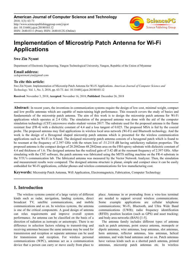
one with a better performance will be fabricated. The block
diagram for the contribution of this research will be shown in
Figure 1.
Figure 1. Block Diagram of Contribution of Research.
4. Proposed Antenna Design I
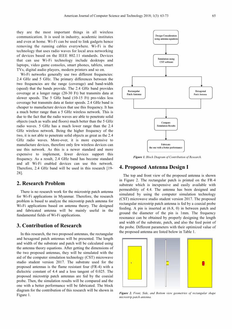
The top and front view of the proposed antenna is shown
in Figure 2. The rectangular patch is printed on the FR-4
substrate which is inexpensive and easily available with
permeability of 4.4. The antenna has been designed and
simulated by using the computer simulation technology
(CST) microwave studio student version 2017. The proposed
rectangular microstrip patch antenna is fed by a coaxial probe
feeding. A pin is inserted at (6.8, 0) in between patch and
ground the diameter of the pin is 1mm. The frequency
resonance can be obtained by properly designing the length
and width of the substrate, patch, and also the feed point of
the probe. Different parameters with their optimized value of
the proposed antenna are listed below in Table 1.
Figure 2. Front, Side, and Bottom view geometries of rectangular shape
microstrip patch antenna.

66 Swe Zin Nyunt: Implementation of Microstrip Patch Antenna for Wi-Fi Applications
Table 1. Dimensions of the proposed design I.
S.No. Parameter Description Dimensions
1. Lg Length of ground plane 55 mm
2. Wg Width of ground plane 50 mm
3. h Height of substrate 1.6mm
4. Wp Patch width 38 mm
5. Lp Patch length 28.03mm
6. t Height of conductor 0.035mm
4. (xp, yp) Feed point (6.8, 0)
5. Substrate material FR-4
5. Proposed Antenna Design II
The simulation of the proposed antenna was done with the
aid of the computer simulation technology (CST) microwave
studio student version 2017. The radiating patch of
hexagonal shape is printed on the FR4-epoxy substrate of
dielectric constant 4.4. The proposed antenna is fed by the
coaxial probe feeding technique and the feeding point is
taken at coordinate as (0, -7). The design consists of a
hexagonal patch which is extended an extra length. Various
parameters considered are indicated in the Table 2. The
proposed antenna geometry is shown in the Figure 3. The
target resonant frequency was obtained by properly designing
the length and width of the substrate, patch, and also the feed
point of the probe. The simulation results show that the
antenna fulfils the requirement of Wi-Fi applications in S
band.
Figure 3. Front, Side and Bottom views of the hexagonal microstrip patch
antenna.
Table 2. Dimensions of the proposed design II.
S.No. Parameter Description Dimensions
1. Lg Length of ground plane 67 mm
2. Wg Width of ground plane 67 mm
3. h Height of substrate 1.6mm
4. Wp Patch width 48.2842 mm
5. Lp Patch length 28.2842mm
6. t Height of conductor 0.035mm
4. (xp, yp) Feed point (0,-7)
5. Substrate material FR-4
6. Test and Results
Antenna plays a pivotal role in our daily life. This is the
reason for so many researches in the field of antenna. There
are a number of ongoing researches intending to the efficient
and compact antennas. Proceeding with the same aim, the
rectangular and hexagonal shaped antenna was designed. It is
to be noted that the performance analysis was especially
based on radiation pattern, bandwidth and return loss. In the
paper work, rectangular and hexagonal shapes of microstrip
patch antenna are presented and the patch antenna with a
better performance will be fabricated.
6.1. Simulation Results of Rectangular Shaped Microstrip
Antenna
In this section, the simulation results such as antenna gain,
voltage standing wave ratio (VSWR), return loss, directivity
and the radiation pattern of the rectangular shaped microstrip
patch antenna will be presented.
6.2. Antenna Gain
Antenna gain describes how much of the power is radiated
in a given direction. The designed antenna has a realize gain
of 3.38 dB at a resonant frequency of 2.4 GHz which means
the antenna is more efficient at this frequency.
Figure 4. Realized gain of the rectangular shaped antenna.
6.3. VSWR
The VSWR value of the proposed antenna is 1.1253055 at
the resonance frequency of 2.4 GHz. VSWR value implies
the impedance matching between the source and the feed is
good, which is an essential requirement for the proper
working of the antenna. The VSWR graph of the proposed
antenna is shown in Figure 5.

American Journal of Computer Science and Technology 2018; 1(3): 63-73 67
Figure 5. VSWR Vs frequency plot of the rectangular patch.
6.4. Return Loss
The designed antenna has a good return loss characteristic that is -24.589026 dB at the resonant frequency of 2.4 GHz.
Increasing negative value of return loss implies the good impedance matching with respect to the reference impedance of 50W.
Return loss could be further improved by using different feeding techniques. The return loss of the rectangular shaped
microstrip antenna is shown in Figure 6.
Figure 6. Return loss Vs frequency plot of the rectangular shaped antenna.
6.5. Directivity
Directivity of the antenna is ability to focus energy in a particular direction when trans-mitting the power during radiation, or
to receive energy better from a particular direction. The directivity below shown as the maximum amount of radiation intensity
that isequal to 6.37 dBi at a resonant frequency of 2.4 GHz. The directivity of the simulated patch antenna is shown in Figure
7.
Figure 7. Directivity of the rectangular shape antenna.

68 Swe Zin Nyunt: Implementation of Microstrip Patch Antenna for Wi-Fi Applications
6.6. Radiation Pattern
The radiation pattern is represented according to the
radiation properties of the antenna as a function of whole
space. Radiation pattern describes how the energy is radiated
out into the space by the antenna or how it is received. For
the resonant frequency 2.4 GHz, the radiation pattern is
nearly linear directional in the azimuthal and elevation plane
for the resonant frequency. The 2-D radiation patterns (Phi=
0 deg) and (Phi= 180 deg) for the elevation and azimuthal
plane of the proposed rectangular microstrip patch antenna
are shown in Figure 8& Figure 9.
Figure 8. Radiation pattern (Phi= 0 deg) of rectangular shape antenna at frequency of 2.4 GHz.
The designed antenna has a good return loss characteristic
that is -24.589026 dB at the frequency of 2.4 GHz.
Increasing negative value of return loss implies the
goodimpedance matching with respect to the reference
impedance of 50ohms. The VSWR of the proposed antenna
shows 1.1253055 at the resonance frequency of 2.4 GHz.
This parameter implies the impedance matching between the
sources to the feed is good, and it is essential requirement for
the proper working of the antenna. The realized gain of the
designed antenna is 3.38 dB at a resonant frequency of 2.4
GHz which means the antenna is more efficient at this
frequency. The directivity is achieved as 6.37 dBi i.e. the
maximum amount of radiation intensity at the frequency of
2.4 GHz. The 2-D radiation patterns for the elevation and
azimuthal plane of the proposed antenna is given in the
Figure 8& Figure 9. Radiation pattern is the graphical
representation of the radiation properties of the antenna as a
function of space. Radiation pattern describes how the energy
is radiated out into the space by the antenna and how it is
received onto to antenna. For the band of the frequency 2.4
GHz, the radiation pattern is linear directional in the
azimuthal and elevation plane. Moreover, the rectangular
shaped antenna has a bandwidth of 76.5 MHz and it can be
applicable in Wi-Fi applications in S band.
Figure 9. Radiation pattern (Phi= 180 deg) of rectangular shape antenna at frequency of 2.4 GHz.
7. Simulation Results of Hexagonal
Shaped Microstrip Antenna
In this section, the simulation results such as antenna gain,
voltage standing wave ratio (VSWR), return loss, directivity
and the radiation pattern of the hexagonal shaped microstrip
patch antenna will be presented.
7.1. Antenna Gain
Antenna gain is the measure of how much power is
radiated in a given direction. The designed antenna has a
good gain of 3.42 dB at a resonant frequency of 2.4 GHz,
which means the antenna is more efficient at this frequency.
The realized gain of the hexagonal shaped microstrip patch
antenna is shown in Figure 10.

American Journal of Computer Science and Technology 2018; 1(3): 63-73 69
Figure 10. Realized gain of the hexagonal shaped antenna.
7.2. VSWR
This is the ratio of maximum value of standing wave voltage to its minimum value. The minimum VSWR for an antenna
would be 1. The antenna with less VSWR has the better return loss compared to the other antenna. The VSWR graph of the
proposed antenna is shown in Figure 11. The VSWR is 1.0565655 at the resonance frequency of 2.4 GHz. VSWR imply as the
voltage standing wave ratio and the impedance matching between the source and the feed is good, which is an essential
requirement for the proper working of the antenna.
Figure 11. VSWR Vs frequency plot of the hexagonal shaped antenna.
7.3. Directivity
The directivity graph shown below is the maximum amount of radiation intensity that is equal to 6.81 dBi is achieved at a
resonant frequency of 2.397 GHz. Directivity is nothing but the ability of antenna to radiate energy in a particular direction as
it is transmitting, and if the energy is receiving, this is also the capture area from a particular direction. The directivity of the
simulated patch antenna is shown in Figure 12.
Figure 12. Directivity of the hexagonal shaped antenna.

70 Swe Zin Nyunt: Implementation of Microstrip Patch Antenna for Wi-Fi Applications
7.4. Radiation Pattern
The 2-D radiation patterns (Phi= 0 deg) and (Phi= 180 deg) for the elevation and azimuthal plane of the proposed hexagonal
shaped microstrip patch antenna are shown in Figure 13 & Figure 14. Radiation pattern is the representation of the radiation of
antenna with the function of space. Radiation pattern describes how the energy is radiated out into the space by the antenna or
how it is received. At the resonant frequency 2.397 GHz, the radiation pattern is linear directional in the elevation plane and
azimuthal angle.
Figure 13. Radiation pattern (Phi= 0 deg) of hexagonal shape antenna at frequency of 2.4 GHz.
Figure 14. Radiation pattern (Phi= 180 deg) of hexagonal shape antenna at frequency of 2.4 GHz.
The designed antenna has a good return loss characteristic
that is -31.211818 dB at the frequency of 2.397 GHz.
Increasing negative value of return loss implies the good
impedance matching with respect to the reference impedance
of 50W. The VSWR of the proposed antenna shows
1.0565655 at the resonance frequency of 2.4 GHz. This
parameter implies the impedance matching between the
sources to the feed is good, and it is essential requirement for
the proper working of the antenna. The realized gain of the
designed antenna is 3.41 dB at a resonant frequency of 2.4
GHz which means the antenna is more efficient at this
frequency. The directivity is achieved as 6.81 dBi i.e. the
maximum amount of radiation intensity at the frequency of
2.397 GHz. The 2-D radiation patterns for the elevation and
azimuthal plane of the proposed antenna is given in Figure
13& Figure 14. Radiation pattern is the graphical
representation of the radiation properties of the antenna as a
function of space. Radiation pattern describes how the energy
is radiated out into the space by the antenna and how it is
received onto to antenna. For the band of the frequency 2.397
GHz, the radiation pattern is linear directional in the
azimuthal and elevation plane. Moreover, the hexagonal
shape antenna has a bandwidth of 75.2 MHz and it can be
applicable in Wi-Fi applications in S band.
Table 3. Comparison of the performance of the patch antennas.
Rectangular Patch
Antenna
Hexagonal Patch
Antenna
Frequency 2.4 GHz 2.397 GHz
Return Loss -24.589026 dB -31.211818 dB
VSWR 1.1253055 1.0565655
Gain 3.38 dB 3.41 dB
Directivity 6.37 dBi 6.81 dBi
Bandwidth 76.5 MHz 75.2 MHz
As shown in Table.3, the hexagonal shaped microstrip
patch antenna has a little bit well in gain, directivity, VSWR
and return loss than the rectangular one. There-fore, the
hexagonal patch antenna will be fabricated and the fabricated
antenna will be measured by the Vector Network Analyzer.
8. Fabrication and Measurement Results
of the Hexagonal Patch
Microstrip patch antennas are the recommended antennas
because mostly they are easy to fabricate. With the help of
CST studio, one can fabricate any type of antenna and

American Journal of Computer Science and Technology 2018; 1(3): 63-73 71
characterize it. All materials which are necessary in the
modelling of an antenna are found in the CST studio. After
the antenna was simulated in the CST studio, the antenna was
fabricated using the MITS milling machine. Based on the
results obtained the patch antenna made was working fine
and it have not deviated much from the real antenna. The
patch antenna which are shown below are the ones which are
similar to the antenna which was designed and characterized.
The one which is shown in Figure 15 is basically used for
Wi-Fi applications.
Figure 15. Fabricated antenna.
While fabricating the antenna, the MITS milling machine
was a little error and ithas been faced the difficulty about the
P1, P2 positioning on the FR-4 substrate. Moreover, while
the machine was doing the routing operation, the milling
machine was suddenly stopped, the computer was also
hanged and cannot do any other operation. The service which
will be given to the machine cannot be done in time before
the research work’s deadline. Therefore, the routing
operation was manually done by a saw in the machine
workshop. The substrate area was reduced 3 mm x 3 mm due
to the manual routing. So, the fabricated substrate is a little
reduced compared to the designed antenna. More-over, the
substrate’s thickness is also uneven due to the unstable
hatching of the milling machine. Then, the fabricated antenna
was measured with the Vector Network analyzer but it cannot
be calibrated between the antenna and Vector Network
analyzer because there is no calibrating head which is
mounted at the network analyzer. After measuring with the
Vector Network Analyzer, the antenna’s return loss is -16.13
dB at the frequency of 2.625 GHz although we can have a
better return loss with a calibrating head. The frequency is
shifted a little due to the error of the milling machine while
fabricating. Since 2.625 GHz frequency is within the Wi-Fi
operation frequency range of 900MHz to 5.8GHz, it can be
applicable in Wi-Fi applications in S band. The measurement
result is shown in Figure 16.
Figure 16. Return loss Vs frequency plot of the fabricated hexagonal shape antenna.

72 Swe Zin Nyunt: Implementation of Microstrip Patch Antenna for Wi-Fi Applications
Comparison of Simulation and Measurement resultsof
Hexagonal Patch Antenna
The return loss of the designed antenna is -31.211818 dB
from the simulation results at resonant frequency of 2.397
GHz and that of the fabricated antenna is -16.14 dB from
measurement results at the resonant frequency of 2.625 GHz.
The required bandwidth is 75.2 MHz while the obtained
bandwidth is 175 MHz. This means that the bandwidth of the
evolved antenna is largely wider than that required in the
simulation. Although the frequency is a little shifted due to
the error of milling machine during fabrication, it has a wider
bandwidth compared to the designed antenna at the resonant
frequency of 2.625 GHz. Moreover, 2.625 GHz is within the
Wi-Fi operation frequency range, so the fabricated antenna
can be applicable in Wi-Fi applications in S band.
Table 4. Comparison of the performance of the hexagonal shaped antenna.
Simulation Results Measurement Results
Return Loss -31.211818 dB -16.14 dB
Bandwidth 75.2 MHz 175 MHz
9. Discussions
The return loss of the designed antenna is -31.211818 dB
from the simulation results at resonant frequency of 2.397
GHz. For the fabrication process, the MITS milling machine
was a little error and it has faced the difficulty about the P1,
P2 positioning on the FR-4 substrate. Moreover, while the
machine was doing the routing operation, the milling
machine was suddenly stopped. The computer was also
hanged and it cannot be done any other operation. Therefore,
the routing operation was manually done by a saw in the
machine workshop. The substrate area was reduced 3 mm 3
mm area due to the manual routing. So, the fabricated
substrate is a little reduced compared to the designed
antenna. Moreover, the substrate’s thickness is also uneven
due to the unstable hatching of the milling machine. And
then, the fabricated antenna was measured with the Vector
Network analyzer but it cannot be calibrated between the
antenna and Vector Network analyzer because there is no
calibrating head which must be mounted at the network
analyzer. After measuring with the Vector Net-work
Analyzer, the antenna’s return loss is -16.13 dB at the
frequency of 2.625 GHz although it can be a better return
loss with calibrating. After measuring the fabricated antenna
with the Vector Network analyzer, the antenna’s return loss is
-16.13 dB and the bandwidth is 175MHz at the frequency of
2.625 GHz. Therefore, the antenna has a good impedance
matching. The required bandwidth is 75.2 MHz while the
obtained bandwidth is 175 MHz. This means that the
bandwidth of the evolved antenna is largely wider than that
required in the simulation by comparing with other studies
[7, 8, 17-19]. Although the frequency is a little shifted due to
the error of the milling machine during fabrication, it has a
wider bandwidth compared to the designed antenna at the
resonant frequency of 2.625 GHz. Since 2.625 GHz
frequency is within the Wi-Fi operating frequency range
(900MHz – 5.8GHz), it can be applicable in Wi-Fi
applications in S band.
10. Conclusion
Microstrip patch antenna is a short radiating structure that
consists of dielectric substrate in between a metallic
conducting patch and ground plane. The rapid development
of modern communication systems such as mobile
communication, wireless communication, satellite
communication and radar applications are required for
portable devices due to some important features including
easy design, light in weight, reduction in size, compatibility
with microwave, millimeter wave integrated circuits, low
production cost and easy fabrication of microstrip antennas.
However, single antenna has limitations that they can utilize
for single application. Although various aspects of the patch
antenna have been broadly discussed in above chapters by for
the sake of convenience, the entire investigations are
summarized in this chapter. From the simulationthe return
loss of the hexagonal shape antenna is -31.211818 dB at the
resonant frequency of 2.397 GHz, increasing negative value
of return loss implies perfect impedance matching of the
reference characteristics impedance of 50 W. The designed
antenna has a good realized gain of 3.42 dB at the resonant
frequency of 2.397 GHz which means the antenna is more
efficient at this frequency. The VSWR of the antenna is
1.0565655 at frequency 2.397 GHz. The directivities i.e. the
maximum amount of radiation intensities that is equal to 6.81
dB at the resonant frequency of 2.397 GHz. The radiation
pattern of the hexagonal shape antenna is linearly polarized
in the elevation plane and azimuthal angle for the resonant
frequency 2.397 GHz. After measuring the fabricated
antenna with the Vector Network analyzer, the antenna’s
return loss is -16.13 dB and the bandwidth is 175MHz at the
frequency of 2.625 GHz. The presented simulation and
measurement results show the usefulness of the proposed
antenna structure for Wi-Fi applications.
Acknowledgements
The author would like to thank many colleagues from the
Antenna Engineering Research Group of the Department of
Electronic Engineering of Yangon Technological University.
References
[1] Annonymous (2018). Microstrip patch Antenna.
[2] AntennaTheory.com (2018). Microstrip antenna. Page Version ID: 855888718.
[3] Balanis, C. A. (2005). Antenna Theory: Analysis and Design, 3rd Edition. Wiley-Interscience, Hoboken, NJ, 3 edition edition.

American Journal of Computer Science and Technology 2018; 1(3): 63-73 73
[4] Bhunia, S. (2014). Microstrip Patch Antenna Design: A Novel Approach. LAP LAMBERT Academic Publishing, S. l.
[5] CST (2017). CST STUDIO SUITE Student Edition.
[6] em: talk (2018). Geometry of rectangular microstrip antenna.
[7] Hemant Kumar Varshney, Mukesh Kumar (2014). Design Characterization of Rectangular Microstrip Patch Antenna for Wi-Fi Application - Inpressco.
[8] K. Dinakaran, M. Vajikabanu, M. Piriyadharsini, D. Rajeshwari (2016). Design of Microstrip Patch Antenna For Wi-Fi Applications.
[9] Narayana, M. V., Immadi, G., Rajkamal, K., Tejaswi, M. S. R. S., Raviteja, V., Chaitanya, A. K., and Rao, B. B. (2012). Microstrip Patch Antenna for C-band RADAR applications with Coaxial fed.
[10] Patchantennablogspot.com (2018). Voltage, Cur-rent and Impedance along the patch’s resonant length.
[11] Petros, A., Zafar, I., and Licul, S. (2003). Reviewing SDARS antenna requirements. icrowaves and Rf, 42: 51–62.
[12] Ramesh Garg, Prakash Bhartia (2001). Microstrip antenna design handbook /.
[13] Research Gate (2018a). Aperture Coupled Feeding.
[14] Research Gate (2018b). Effective length of microstrip patch antenna.
[15] Research Gate (2018c). Microstrip Line and Electric Field lines.
[16] Research Gate (2018d). Proximity Coupled Feeding.
[17] S. ANUSHA, Y. (2017). Hexagonal Shaped Micro-strip Patch Antenna for Wi-Fi Application, volume Vol. 5, Issue 3. Y. Balaraju.
[18] Shodhganga Inflibnet.ac (2009). Substrate Material Selection and its importance.
[19] Shumba, P. (2017). Design and characterization of a microstrip patch antenna for Wi-Fi. Koteswa, Anusha.
[20] Slideshare.net (2018). Basic microstrip patch antenna shapes.
[21] Springer Link (2018). Microstrip Line Feeding.
[22] Stutzman, W. L. and Thiele, G. A. (2013). Antenna Theory and Design. John Wiley & Sons. Google-Books-ID: xhZRA1K57wIC.
[23] Tutorials Point (2018). Antenna pattern with main, back, and side lobes.
[24] Weng, Z., Guo, D., Wu, Y., Li, M., Hu, J., Zeng, W., Li, X., and Zeng, S. (2015). A 2.45ghz microstrip patch antenna evolved for WiFi application. In 2015 IEEE Congress on Evolutionary Computation (CEC), pages 1191–1195.
[25] Wiki (2018). Microstrip antenna wiki.com.
[26] Wong, K.-L. (2004). Design of Nonplanar Microstrip Antennas and Transmission Lines. John Wiley & Sons.
[27] Wong, K.-L., Liu, Y.-H., and Huang, C.-Y. (1994). Generalized transmission-line model for cylindrical-rectangular microstrip antennas. Microwave and Optical Technology Letters, 7(16): 729–732.
[28] www.radartutorial.eu (2018). Radar Basics Patch Antennas.