Embed Size (px)
Citation preview
INTERNATIONAL JOURNAL OF CIRCUIT THEORY AND APPLICATIONS
Int. J. Circ. ¹heor. Appl., 26, 551—566 (1998)
IMPLEMENTATION OF LARGE-NEIGHBOURHOODNON-LINEAR TEMPLATES ON THE CNN UNIVERSAL MACHINE
LASZLO KEK* AND AKOS ZARANDY
Analogical and Neural Computing Systems Laboratory, Computer and Automation Institute, Hungarian Academy of Sciences,POB 63, H-1518 Budapest, Hungary
SUMMARY
In this paper we present a general method for implementing certain types of arbitrary large neighbourhood non-linearcontrol (B) templates on the cellular neural network universal machine (CNNUM). First, we show how a 3]3 non-linearB template can be replaced by a set of linear ones. We thereby obtain an analogic algorithm that, by using lineartemplates, yields the same result as when applying the original non-linear template. It is then shown how the templatedecomposition problem can be solved for large neighbourhood non-linear B templates. Thirdly, the question of templatedecomposition is discussed for arbitrary templates in case of discrete time CNN (DTCNN). Examples are given tohighlight the main steps of the algorithm. The necessary and sufficient conditions for realizing the proposed method onany CNNUM chip are also specified. An idea for solving the non-linear feedback (A) template decomposition problem isalso proposed. ( 1998 John Wiley & Sons, Ltd.
KEY WORDS: cellular neural networks; large-neighbourhood non-linear templates; template decomposition
1. INTRODUCTION
Cellular neural networks (CNNs)1,2 are excellently suited for solving numerous image-processing tasks.When considering the CNN paradigm3 we can distinguish linear and non-linear templates.5 Non-lineartemplates play an important role in solving many problems. However, of the few non-programmable7—9 andprogrammable10—13 VLSI CNN chips that have been developed, only linear templates can be implementedmainly due to difficulties of realizing non-linearity in hardware. Therefore, now methods are needed thatallow us to implement non-linear templates on current (linear) CNNUM chips. In this paper, we presenta general method for replacing (producing) a 3]3 non-linear B template with piece-wise linear functions bya set of linear templates, i.e., by applying linear templates and logic operations. This results in an equivalentanalogic algorithm that can be implemented on the CNNUM.4 This method will be called the non-linear-to-linear method. An idea for solving the problem in case of non-linear A templates is also proposed.
We discuss the question of how an arbitrary size non-linear B template can be implemented on theCNNUM. Here we will use some ideas concerning the solution of the template decomposition problem.14—16
Finally, it will be shown that certain types of non-linear templates of arbitrary size, including A templates,can be implemented on the DTCNN Universal Machine using 3]3 linear templates.
2. THE BASIC IDEA OF THE NON-LINEAR-TO-LINEAR METHOD
We consider only those 3]3 non-linear templates in which the A template is linear. Furthermore, it isassumed that non-linear functions which determine non-linear templates are piece-wise linear functions, andthe input is time invariant.
*Correspondence to: Laszlo Kek, Analogical and Neural Computing Systems Laboratory, Computer and Automation Institute,Hungarian Academy of Sciences, POB 63, H-1518 Budapest, Hungary. Email: [email protected]
Contract grant sponsor: OTKA (Hungarian National Research Fund); contract grant number: T007308
CCC 0098—9886/98/060551—16$17.50 Received 15 May 1997( 1998 John Wiley & Sons, Ltd. Revised 19 November 1997
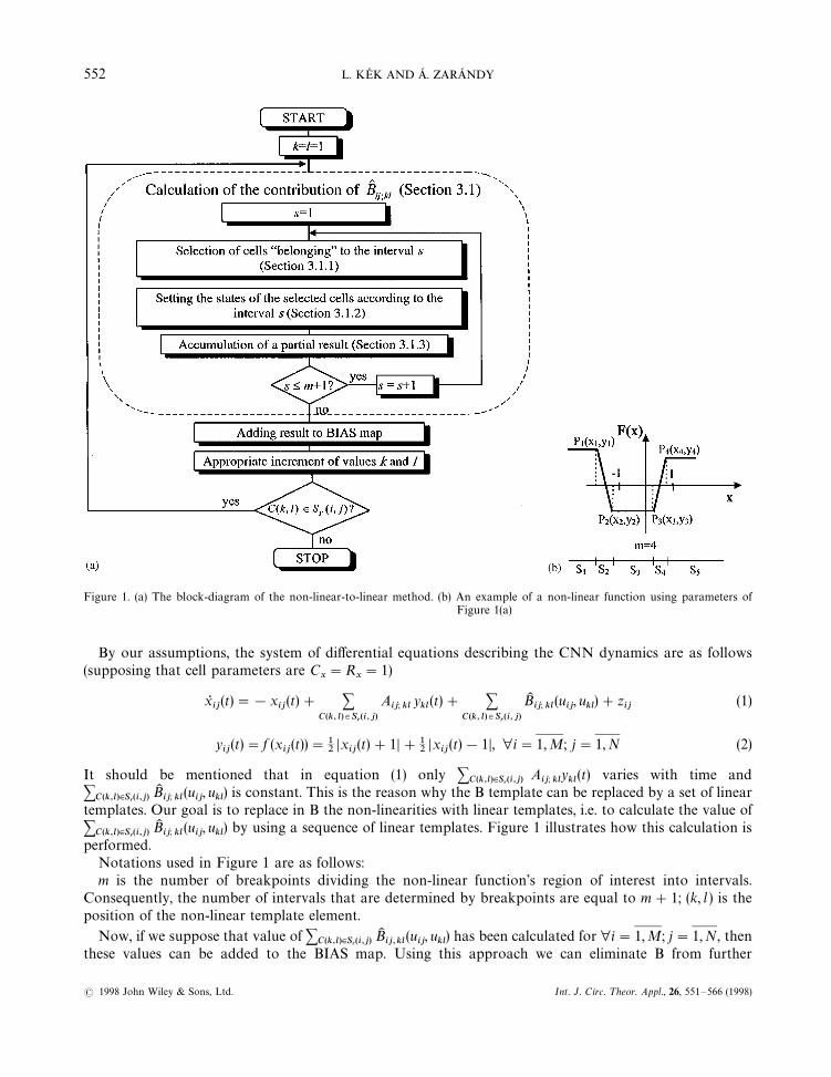
Figure 1. (a) The block-diagram of the non-linear-to-linear method. (b) An example of a non-linear function using parameters ofFigure 1(a)
By our assumptions, the system of differential equations describing the CNN dynamics are as follows(supposing that cell parameters are C
x"R
x"1)
xRij(t)"!x
ij(t)# +
C(k, l)3Sr(i,j)
Aij; kl
ykl(t)# +
C(k, l)3Sr(i,j)
BKij; kl
(uij, u
kl)#z
ij(1)
yij(t)"f (x
ij(t))"1
2Dx
ij(t)#1D#1
2Dx
ij(t)!1D, ∀i"1, M; j"1, N (2)
It should be mentioned that in equation (1) only +C(k,l)|Sr(i,j)
Aij; kl
ykl(t) varies with time and
+C(k,l)|Sr(i,j)
BKij; kl
(uij, u
kl) is constant. This is the reason why the B template can be replaced by a set of linear
templates. Our goal is to replace in B the non-linearities with linear templates, i.e. to calculate the value of+
C(k,l)|Sr(i,j)BKij; kl
(uij, u
kl) by using a sequence of linear templates. Figure 1 illustrates how this calculation is
performed.Notations used in Figure 1 are as follows:m is the number of breakpoints dividing the non-linear function’s region of interest into intervals.
Consequently, the number of intervals that are determined by breakpoints are equal to m#1; (k, l ) is theposition of the non-linear template element.
Now, if we suppose that value of +C(k,l)|Sr(i,j)
BKij,kl
(uij, u
kl) has been calculated for ∀i"1,M; j"1,N, then
these values can be added to the BIAS map. Using this approach we can eliminate B from further
552 L. KEK AND A. ZARANDY
( 1998 John Wiley & Sons, Ltd. Int. J. Circ. ¹heor. Appl., 26, 551—566 (1998)
calculations. This means that B becomes zero and the rest of the template elements (Aij; kl
, zij) remain
unchanged. When executing this template (using the pre-calculated BIAS map) we get the desired result, thatis, the result we get when executing the original non-linear template.
3. DETAILED ANALYSIS OF THE NON-LINEAR-TO-LINEAR METHOD
Now, we introduce, step by step and examine in detail, the method that was briefly discussed in Section 2 (seeFigure 1). We now demonstrate how the calculation of the contribution of +
C(k,l)|Sr(i,j)BK
ij,kl(u
ij, u
kl) is
performed.
3.1. Calculation of the Contribution of BK ij; kl
Let F(x) be the actual non-linear function that determines BKij; kl
(an example can be seen on Figure 1(b)).Furthermore, let P
1(x
1, y
1), P
2(x
2, y
2),2 ,P
m(x
m, y
m) be the breakpoints that occur in the non-linear
function. It is supposed that for ∀x3(!R,R) F(x) 3[!1, 1]. The case when & x3(!R,R) F(x) N [!1, 1]will be discussed in Section 3.3.
Non-linear functions which can be decomposed into a sequence of linear templates and at the same timeare most often used in practice are as follows:
BKij,kl
(uij, u
kl)"F(au
ij#bu
kl) (3)
where a, b3R.We will examine how the value of F(x) can be calculated in this case. Since the value of F(x) changes or may
change from one interval to the other, it has to be calculated with respect to the interval. In other words, ithas to be determined which interval x belongs to. In addition, the state of the given cell has to be set (the valueof F(x) has to be calculated) according to the selected interval. The task is solved in the following way. Wetake intervals one after the other, and those cell states that ‘belong’ to the selected interval are drivenaccording to the function F. Next, we show how those cells that ‘belong’ to a given interval are selected.
3.1.1. Selection of cells *Belonging+ to a given interval. Consider any interval (xq, x
q`1). The selection of
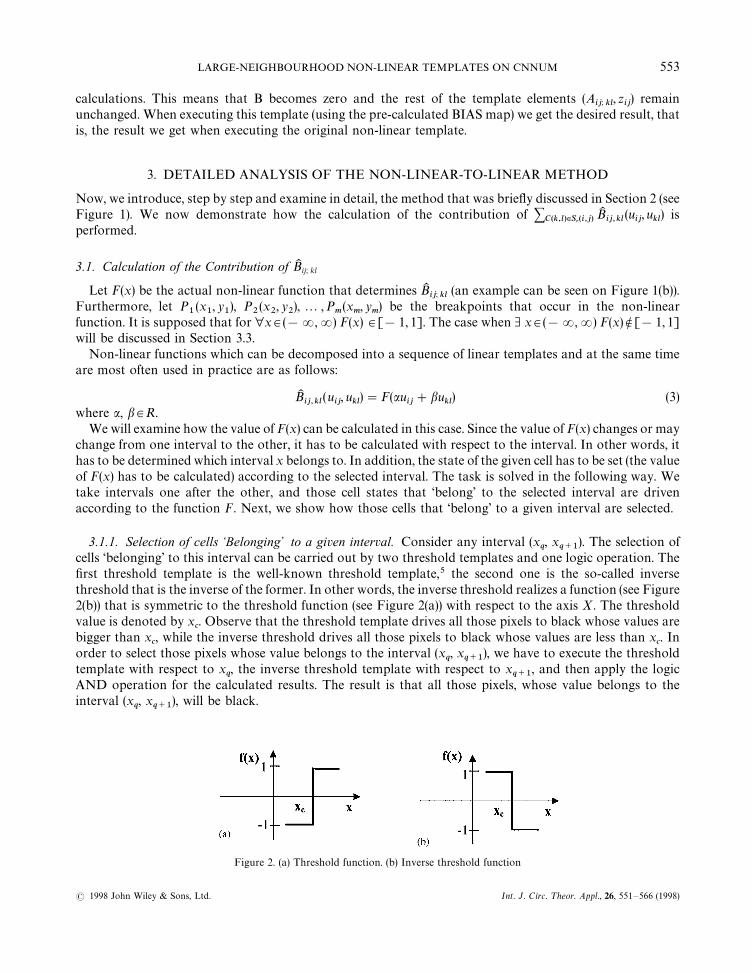
cells ‘belonging’ to this interval can be carried out by two threshold templates and one logic operation. Thefirst threshold template is the well-known threshold template,5 the second one is the so-called inversethreshold that is the inverse of the former. In other words, the inverse threshold realizes a function (see Figure2(b)) that is symmetric to the threshold function (see Figure 2(a)) with respect to the axis X. The thresholdvalue is denoted by x
c. Observe that the threshold template drives all those pixels to black whose values are
bigger than xc, while the inverse threshold drives all those pixels to black whose values are less than x
c. In
order to select those pixels whose value belongs to the interval (xq, x
q`1), we have to execute the threshold
template with respect to xq, the inverse threshold template with respect to x
q`1, and then apply the logic
AND operation for the calculated results. The result is that all those pixels, whose value belongs to theinterval (x
q, x
q`1), will be black.
Figure 2. (a) Threshold function. (b) Inverse threshold function
LARGE-NEIGHBOURHOOD NON-LINEAR TEMPLATES ON CNNUM 553
( 1998 John Wiley & Sons, Ltd. Int. J. Circ. ¹heor. Appl., 26, 551—566 (1998)
Now, let us examine in detail the templates just mentioned. It is important to emphasize that for thetemplates mentioned henceforth, the Initial State will be equal to zero. When (k, l )"(1,1) the threshold andinverse threshold templates with respect to equation (3) are as follows (for other values of (k, l ), thesetemplates can be generated similarly):
Threshold template Inverse threshold template
A"
0 0 0
0 2 0
0 0 0
, B"
b 0 0
0 a 0
0 0 0
, z"!xc; A"
0 0 0
0 2 0
0 0 0
, B"
!b 0 0
0 !a 0
0 0 0
, z"xc
Using these templates we can select those cells for which auij#bu
kl3(x
q, x
q`1). This way we obtain a map on
which the black pixels indicate the cells of interest whose states are to be driven into a desired value offunction F. In a real application, this map is to be used as a fixed state mask.
3.1.2. Setting the states of the selected cells according to a given interval. Let us continue the examination ofinterval (x
q, x
q`1). In order to calculate the value of F(x) for ∀x3(x
q, x
q`1) we need to consider the equation
of a line crossing points Pq(x
q, y
q) and P
q`1(x
q`1, y
q`1). Indeed, according to our assumptions F(x) is linear
on the interval (xq, x
q`1) (see Section 2). The equation of a line crossing points P
qand P
q`1(Figure 1(b)) is as
follows:
x!xq
xq`1
!xq
"
y!yq
yq`1
!yq
Q y"kx#yq!kx
qwhere k"
yq`1
!yq
xq`1
!xq
In the CNN theory the above equation can be handled as an input—output relationship. This relationshipwith respect to equation (3) can be accomplished by using the following template:
A"
0 0 0
0 0 0
0 0 0
, B"
kb 0 0
0 ka 0
0 0 0
, z"yq!kx
q
It is necessary to use fixed state mask when applying this template. The appropriate fixed state mask can beproduced according to the method described in Section 3.1.1.
3.1.3. Accumulation of a partial result. Observe that during calculations the choice of setting the initialstate to zero was not arbitrary. When using a fixed state mask only the states of selected cells change and theunselected ones remain unchanged. This makes it possible to accumulate partial results in analog memory.Indeed, a given cell cannot ‘belong’ to different intervals at the same time. So if we add the partial results thatactually ‘belong’ to different intervals, the states of the cells having already been calculated, remainunchanged. Applying the method described in Sections 3.1.1—3.1.2 for every interval, the value of BK
ij,kl(u
ij, u
kl)
can be calculated with respect to each cell.Adding two analog values can be performed in different ways on the CNNUM. This issue was examined in
detail in Reference 16.
3.2. Calculation of +C(k,l)|Sr(i,j)
BKij; kl
(uij, u
kl)
In order to calculate the value of +C(k,l)|Sr(i,j)
BKij; kl
(uij, u
kl) we use an analog memory cell called ACCU. It
accumulates values of BKij,kl
(uij, u
kl) that have already been calculated. When calculating a new BK
ij,kl(u
ij, u
kl), it
is added to ACCU, and the result is written back into ACCU.
554 L. KEK AND A. ZARANDY
( 1998 John Wiley & Sons, Ltd. Int. J. Circ. ¹heor. Appl., 26, 551—566 (1998)
Remark. The best way to add two analog values is to use the analog adder at the local analog output unit(LAOU) of a cell on the CNNUM.16 In our task it is possible that at least one of the values to be added doesnot belong to the interval [!1,1]. For this reason, when using a template method for adding two analogvalues,16 it is not guaranteed that the result will fall within the linear region, even if we use some scaling. So inthis case the correct result of the addition will appear on the state and therefore the state value has to be savedinto ACCU.
The remaining steps to be done are as follows:
f modify the original template: B"0; values of (Aij; kl
, zij) remain unchanged;
f modify the original BIAS map that is equal to zij
: addition of ACCU and BIAS;f execute the modified template using the modified BIAS map.
3.3. What to do if &x3(!R,R)F (x) N [!1,1]
Let (xq,x
q`1)-(!R,R) be the interval for which the following statement is true: &x3(x
q, x
q`1)
F(x) N [!1,1]. Suppose that for ∀ x3(xq,x
q`1) F(x)3[!a, a], where a'1. The output value of a CNN cell
can only be inside the interval [!1,1]. Therefore [!a, a] is mapped onto [!1,1], and the value ofBKij, kl
(uij, u
kl) is calculated as if [!a, a] would coincide [!1,1]. Afterwards, the calculated result has to be
multiplied by a, that is, [!1,1] has to be mapped onto [!a, a]. This can be done in such a way that for theaccumulation of a partial result the following template is to be used: A"[0], B"[a], z"0. Here the valueto be multiplied has to be loaded into INPUT, and the other one has to be loaded into the space variantBIAS. As mentioned earlier the correct result will appear on the State.
The method just mentioned has to be applied for each interval (xq,x
q`1) for which the following statement
is true: &x3(xq,x
q`1) F(x) N [!1,1]. The accumulation of partial results calculated this way can also be done
according to the method described in Section 3.1.3. In conclusion, we can replace any 3]3 non-linearB template with a set of linear ones.
4. EXPERIMENTAL RESULTS CONCERNING THE NON-LINEAR-TO-LINEAR METHOD
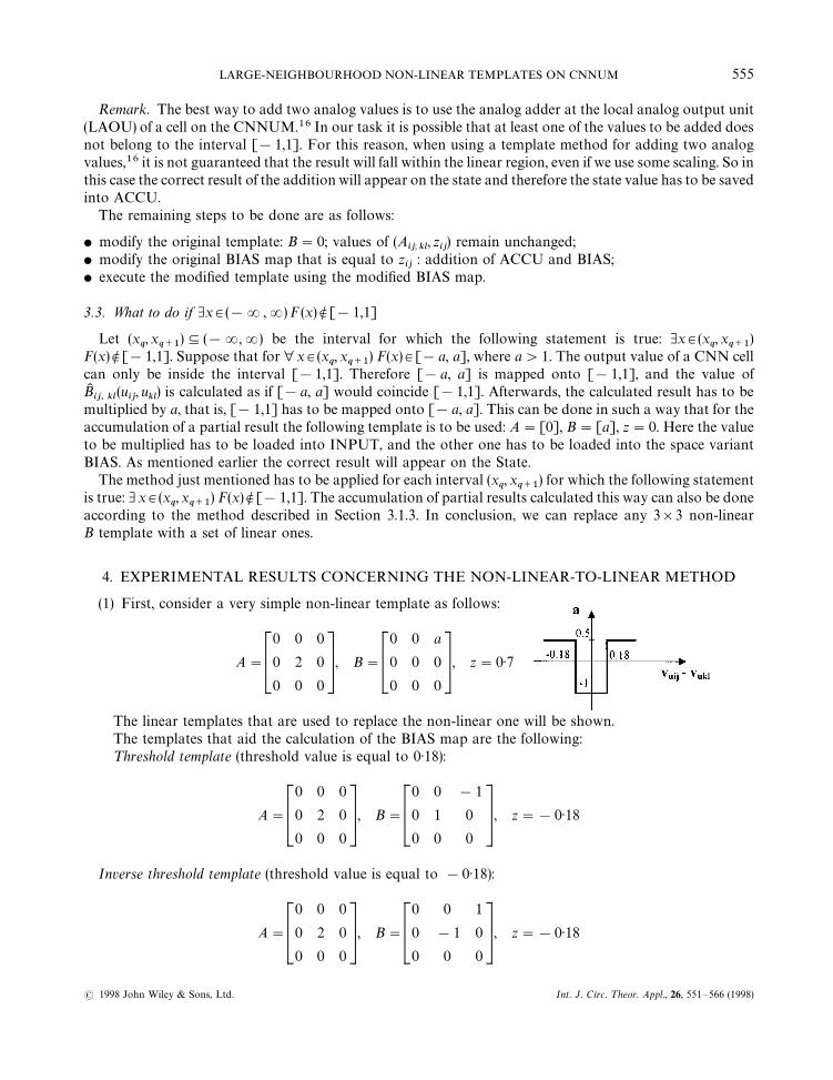
(1) First, consider a very simple non-linear template as follows:
A"
0 0 0
0 2 0
0 0 0
, B"
0 0 a
0 0 0
0 0 0
, z"0)7
The linear templates that are used to replace the non-linear one will be shown.The templates that aid the calculation of the BIAS map are the following:¹hreshold template (threshold value is equal to 0)18):
A"
0 0 0
0 2 0
0 0 0
, B"
0 0 !1
0 1 0
0 0 0
, z"!0)18
Inverse threshold template (threshold value is equal to !0)18):
A"
0 0 0
0 2 0
0 0 0
, B"
0 0 1
0 !1 0
0 0 0
, z"!0)18
LARGE-NEIGHBOURHOOD NON-LINEAR TEMPLATES ON CNNUM 555
( 1998 John Wiley & Sons, Ltd. Int. J. Circ. ¹heor. Appl., 26, 551—566 (1998)
¹emplate that is used to set the state of a cell into a given value:For cells ‘belonging’ to (!R,!0)18)X(0)18,R) (value to be set is equal to 0)5):
A"
0 0 0
0 0 0
0 0 0
, B"
0 0 0
0 0 0
0 0 0
, z"0)5
For cells ‘belonging’ to (!0)18,0)18) (value to be set is equal to!1):
A"
0 0 0
0 0 0
0 0 0
, B"
0 0 0
0 0 0
0 0 0
, z"!1
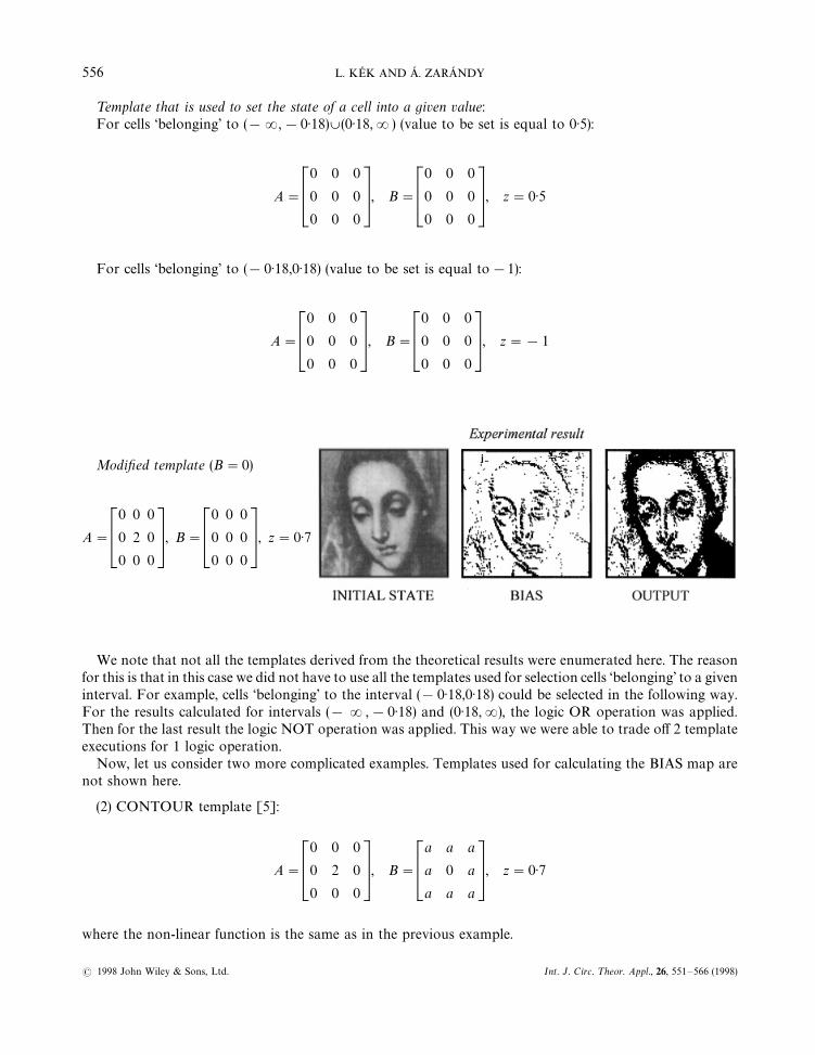
Modified template (B"0)
A"
0 0 0
0 2 0
0 0 0
, B"
0 0 0
0 0 0
0 0 0
, z"0)7
We note that not all the templates derived from the theoretical results were enumerated here. The reasonfor this is that in this case we did not have to use all the templates used for selection cells ‘belonging’ to a giveninterval. For example, cells ‘belonging’ to the interval (!0)18,0)18) could be selected in the following way.For the results calculated for intervals (!R,!0)18) and (0)18,R), the logic OR operation was applied.Then for the last result the logic NOT operation was applied. This way we were able to trade off 2 templateexecutions for 1 logic operation.
Now, let us consider two more complicated examples. Templates used for calculating the BIAS map arenot shown here.
(2) CONTOUR template [5]:
A"
0 0 0
0 2 0
0 0 0
, B"
a a a
a 0 a
a a a
, z"0)7
where the non-linear function is the same as in the previous example.
556 L. KEK AND A. ZARANDY
( 1998 John Wiley & Sons, Ltd. Int. J. Circ. ¹heor. Appl., 26, 551—566 (1998)
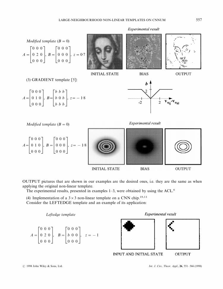
Modified template (B"0)
A"
0 0 0
0 2 0
0 0 0
, B"
0 0 0
0 0 0
0 0 0
, z"0)7
(3) GRADIENT template [5]:
A"
0 0 0
0 1 0
0 0 0
, B"
b b b
b 0 b
b b b
, z"!1)8
Modified template (B"0)
A"
0 0 0
0 1 0
0 0 0
, B"
0 0 0
0 0 0
0 0 0
, z"!1)8
OUTPUT pictures that are shown in our examples are the desired ones, i.e. they are the same as whenapplying the original non-linear template.
The experimental results, presented in examples 1—3, were obtained by using the ACL.6
(4) Implementation of a 3]3 non-linear template on a CNN chip.10,11Consider the LEFTEDGE template and an example of its application:
¸eftedge template
A"
0 0 0
0 2 0
0 0 0
, B"
0 0 0
b 0 0
0 0 0
, z"!1
LARGE-NEIGHBOURHOOD NON-LINEAR TEMPLATES ON CNNUM 557
( 1998 John Wiley & Sons, Ltd. Int. J. Circ. ¹heor. Appl., 26, 551—566 (1998)
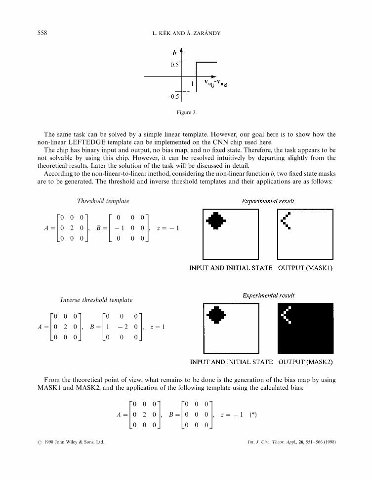
Figure 3.
The same task can be solved by a simple linear template. However, our goal here is to show how thenon-linear LEFTEDGE template can be implemented on the CNN chip used here.
The chip has binary input and output, no bias map, and no fixed state. Therefore, the task appears to benot solvable by using this chip. However, it can be resolved intuitively by departing slightly from thetheoretical results. Later the solution of the task will be discussed in detail.
According to the non-linear-to-linear method, considering the non-linear function b, two fixed state masksare to be generated. The threshold and inverse threshold templates and their applications are as follows:
¹hreshold template
A"
0 0 0
0 2 0
0 0 0
, B"
0 0 0
!1 0 0
0 0 0
, z"!1
Inverse threshold template
A"
0 0 0
0 2 0
0 0 0
, B"
0 0 0
1 !2 0
0 0 0
, z"1
From the theoretical point of view, what remains to be done is the generation of the bias map by usingMASK1 and MASK2, and the application of the following template using the calculated bias:
A"
0 0 0
0 2 0
0 0 0
, B"
0 0 0
0 0 0
0 0 0
, z"!1 (*)
558 L. KEK AND A. ZARANDY
( 1998 John Wiley & Sons, Ltd. Int. J. Circ. ¹heor. Appl., 26, 551—566 (1998)
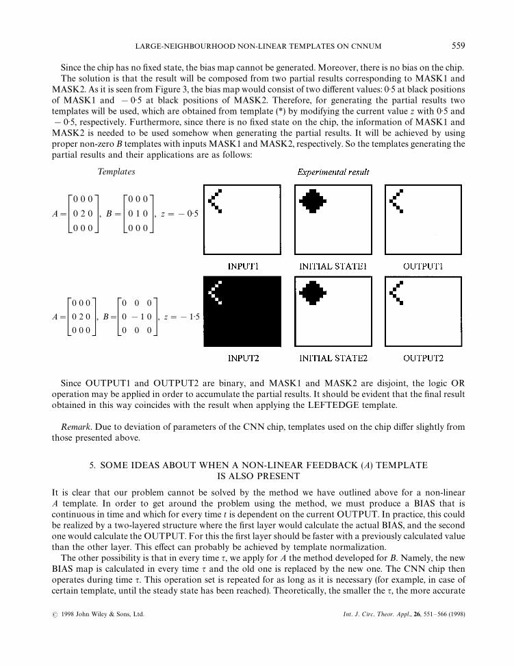
Since the chip has no fixed state, the bias map cannot be generated. Moreover, there is no bias on the chip.The solution is that the result will be composed from two partial results corresponding to MASK1 and
MASK2. As it is seen from Figure 3, the bias map would consist of two different values: 0)5 at black positionsof MASK1 and !0)5 at black positions of MASK2. Therefore, for generating the partial results twotemplates will be used, which are obtained from template (*) by modifying the current value z with 0)5 and!0)5, respectively. Furthermore, since there is no fixed state on the chip, the information of MASK1 andMASK2 is needed to be used somehow when generating the partial results. It will be achieved by usingproper non-zero B templates with inputs MASK1 and MASK2, respectively. So the templates generating thepartial results and their applications are as follows:
¹emplates
A"
0 0 0
0 2 0
0 0 0
, B"
0 0 0
0 1 0
0 0 0
, z"!0)5
A"
0 0 0
0 2 0
0 0 0
, B"
0 0 0
0 !1 0
0 0 0
, z"!1)5
Since OUTPUT1 and OUTPUT2 are binary, and MASK1 and MASK2 are disjoint, the logic ORoperation may be applied in order to accumulate the partial results. It should be evident that the final resultobtained in this way coincides with the result when applying the LEFTEDGE template.
Remark. Due to deviation of parameters of the CNN chip, templates used on the chip differ slightly fromthose presented above.
5. SOME IDEAS ABOUT WHEN A NON-LINEAR FEEDBACK (A) TEMPLATEIS ALSO PRESENT
It is clear that our problem cannot be solved by the method we have outlined above for a non-linearA template. In order to get around the problem using the method, we must produce a BIAS that iscontinuous in time and which for every time t is dependent on the current OUTPUT. In practice, this couldbe realized by a two-layered structure where the first layer would calculate the actual BIAS, and the secondone would calculate the OUTPUT. For this the first layer should be faster with a previously calculated valuethan the other layer. This effect can probably be achieved by template normalization.
The other possibility is that in every time q, we apply for A the method developed for B. Namely, the newBIAS map is calculated in every time q and the old one is replaced by the new one. The CNN chip thenoperates during time q. This operation set is repeated for as long as it is necessary (for example, in case ofcertain template, until the steady state has been reached). Theoretically, the smaller the q, the more accurate
LARGE-NEIGHBOURHOOD NON-LINEAR TEMPLATES ON CNNUM 559
( 1998 John Wiley & Sons, Ltd. Int. J. Circ. ¹heor. Appl., 26, 551—566 (1998)
the result. But in practice, with decreasing q the number of operations to be conducted increases which resultsin an unwanted accumulation of errors.
It would be an interesting problem to find an optimal value for q.In case of DTCNN no problem occurs when replacing the non-linear A template with linear ones, because
in that case the new BIAS map can be calculated in each step without any difficulty.
6. SOLUTION FOR THE LARGE-NEIGHBOURHOOD NON-LINEAR (B) TEMPLATE PROBLEM
Using the method, introduced in the previous section, we are now able to implement 3]3 templates on theCNNUM in which A is linear and B is non-linear of certain type. Furthermore, an idea has been proposedconcerning the question how the problem could be solved in the case of a non-linear A template.
The question now arises whether non-linear B templates of an arbitrary-sized neighbourhood can also beimplemented on the CNNUM. This problem can now be reduced to the template decomposition problem.There are a few papers14—16 that address this question. The template decomposition problem for theB template has already been solved and an analogic algorithm has been proposed for the CNNUM.16
Here we propose an algorithm that combines the non-linear-to-linear method with some elements of thetemplate decomposition method. The main idea is to eliminate B from the calculations by generating anappropriate space-variant BIAS map.
Suppose that we have a B template of any size. It is clear that if B is linear the problem could be solved bythe partition-shift algorithm.16 Let us consider the case of a non-linear B template.
If we suppose that the partitioning of template B to 3]3 parts (subtemplates) has already been done, wemust still apply the non-linear-to-linear method for each subtemplate and appropriately accumulate thepartial results.16 This is the way our algorithm works.
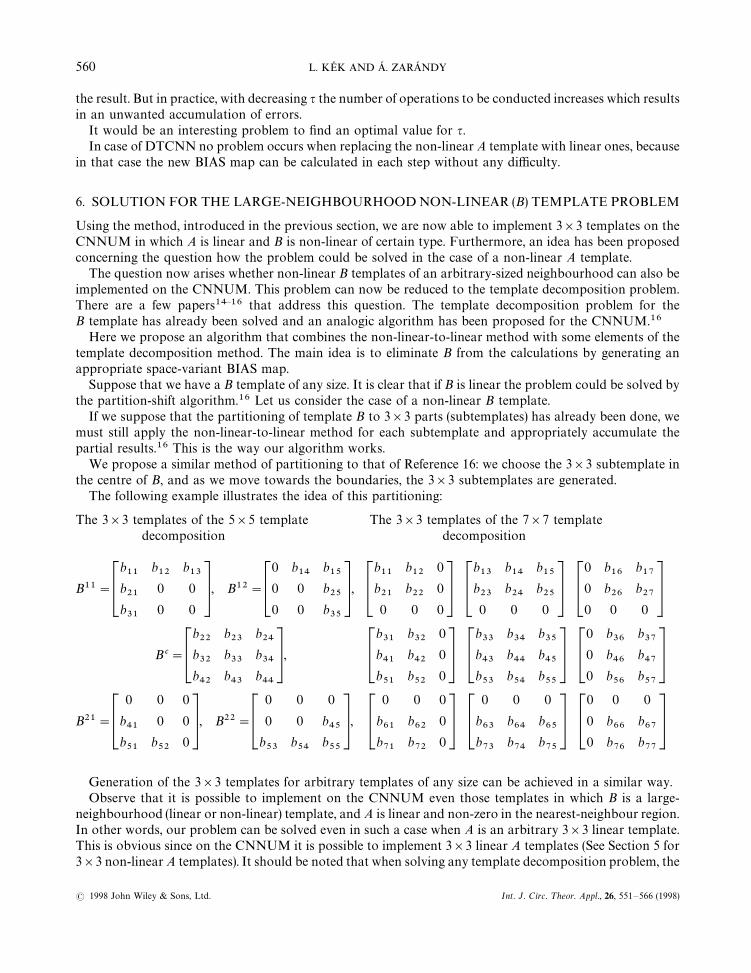
We propose a similar method of partitioning to that of Reference 16: we choose the 3]3 subtemplate inthe centre of B, and as we move towards the boundaries, the 3]3 subtemplates are generated.
The following example illustrates the idea of this partitioning:
The 3]3 templates of the 5]5 templatedecomposition
The 3]3 templates of the 7]7 templatedecomposition
B11"
b11
b12
b13
b21
0 0
b31
0 0
, B12"
0 b14
b15
0 0 b25
0 0 b35
,
b11
b12
0
b21
b22
0
0 0 0
b13
b14
b15
b23
b24
b25
0 0 0
0 b16
b17
0 b26
b27
0 0 0
B c"
b22
b23
b24
b32
b33
b34
b42
b43
b44
,
b31
b32
0
b41
b42
0
b51
b52
0
b33
b34
b35
b43
b44
b45
b53
b54
b55
0 b36
b37
0 b46
b47
0 b56
b57
B21"
0 0 0
b41
0 0
b51
b52
0
, B22"
0 0 0
0 0 b45
b53
b54
b55
,
0 0 0
b61
b62
0
b71
b72
0
0 0 0
b63
b64
b65
b73
b74
b75
0 0 0
0 b66
b67
0 b76
b77
Generation of the 3]3 templates for arbitrary templates of any size can be achieved in a similar way.Observe that it is possible to implement on the CNNUM even those templates in which B is a large-
neighbourhood (linear or non-linear) template, and A is linear and non-zero in the nearest-neighbour region.In other words, our problem can be solved even in such a case when A is an arbitrary 3]3 linear template.This is obvious since on the CNNUM it is possible to implement 3]3 linear A templates (See Section 5 for3]3 non-linear A templates). It should be noted that when solving any template decomposition problem, the
560 L. KEK AND A. ZARANDY
( 1998 John Wiley & Sons, Ltd. Int. J. Circ. ¹heor. Appl., 26, 551—566 (1998)
CNN structure (chip) used for implementation has to possess boundary cells in order to prevent the loss ofthe boundary results. This fact is also highlighted in Reference 15.
Our algorithm consists of the following steps:1. Partitioning: generation of 3]3 templates,2. Application of non-linear-to-linear method for an actual 3]3 template,3. Accumulation of a partial result;16 choosing the next 3]3 template (if exists) and going to 2,4. Application of the modified template using the modified BIAS map (see Section 3.2).
6.1. Experimental results
Here we will consider large neighbourhood linear templates. It is not important whether the template islinear or not since here we only show that our idea of template partitioning works in a real application.
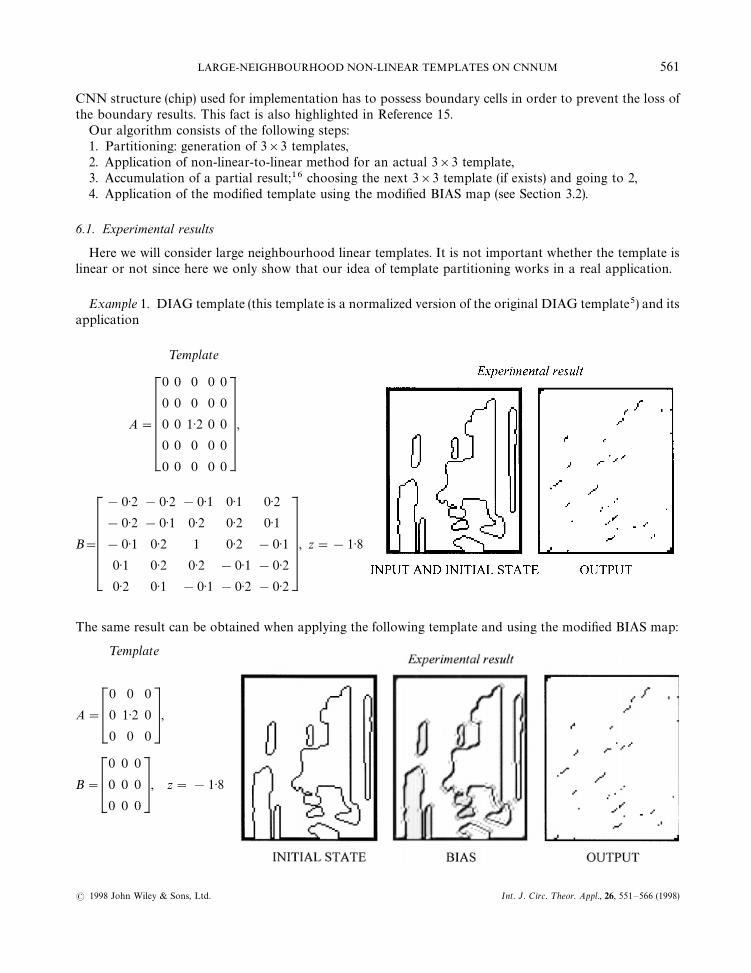
Example 1. DIAG template (this template is a normalized version of the original DIAG template5) and itsapplication
¹emplate
A"
0 0 0 0 0
0 0 0 0 0
0 0 1)2 0 0
0 0 0 0 0
0 0 0 0 0
,
B"
!0)2 !0)2 !0)1 0)1 0)2
!0)2 !0)1 0)2 0)2 0)1
!0)1 0)2 1 0)2 !0)1
0)1 0)2 0)2 !0)1 !0)2
0)2 0)1 !0)1 !0)2 !0)2
, z"!1)8
The same result can be obtained when applying the following template and using the modified BIAS map:
¹emplate
A"
0 0 0
0 1)2 0
0 0 0
,
B"
0 0 0
0 0 0
0 0 0
, z"!1)8
LARGE-NEIGHBOURHOOD NON-LINEAR TEMPLATES ON CNNUM 561
( 1998 John Wiley & Sons, Ltd. Int. J. Circ. ¹heor. Appl., 26, 551—566 (1998)
Here the BIAS map has been calculated by using the template decomposition method, the experimentalresult has been obtained using the ACL.6
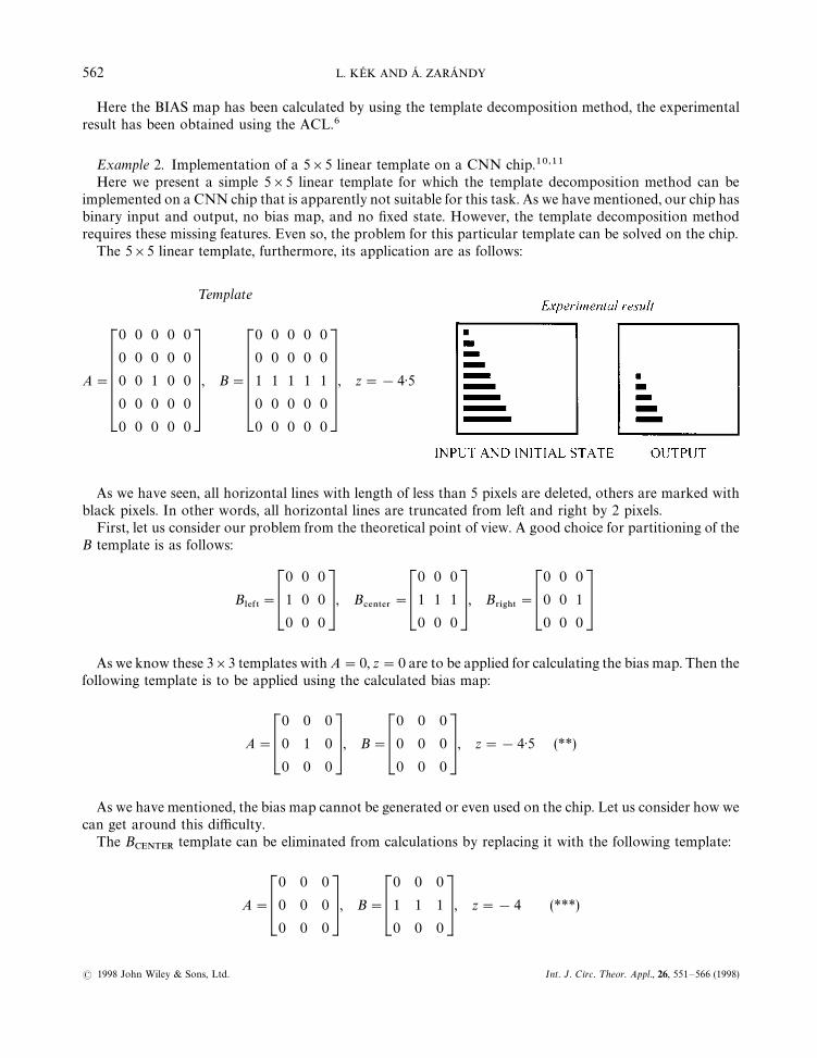
Example 2. Implementation of a 5]5 linear template on a CNN chip.10,11Here we present a simple 5]5 linear template for which the template decomposition method can be
implemented on a CNN chip that is apparently not suitable for this task. As we have mentioned, our chip hasbinary input and output, no bias map, and no fixed state. However, the template decomposition methodrequires these missing features. Even so, the problem for this particular template can be solved on the chip.
The 5]5 linear template, furthermore, its application are as follows:
¹emplate
A"
0 0 0 0 0
0 0 0 0 0
0 0 1 0 0
0 0 0 0 0
0 0 0 0 0
, B"
0 0 0 0 0
0 0 0 0 0
1 1 1 1 1
0 0 0 0 0
0 0 0 0 0
, z"!4)5
As we have seen, all horizontal lines with length of less than 5 pixels are deleted, others are marked withblack pixels. In other words, all horizontal lines are truncated from left and right by 2 pixels.
First, let us consider our problem from the theoretical point of view. A good choice for partitioning of theB template is as follows:
B-%&5
"
0 0 0
1 0 0
0 0 0
, B#%/5%3
"
0 0 0
1 1 1
0 0 0
, B3*')5
"
0 0 0
0 0 1
0 0 0
As we know these 3]3 templates with A"0, z"0 are to be applied for calculating the bias map. Then thefollowing template is to be applied using the calculated bias map:
A"
0 0 0
0 1 0
0 0 0
, B"
0 0 0
0 0 0
0 0 0
, z"!4)5 (**)
As we have mentioned, the bias map cannot be generated or even used on the chip. Let us consider how wecan get around this difficulty.
The BCENTER
template can be eliminated from calculations by replacing it with the following template:
A"
0 0 0
0 0 0
0 0 0
, B"
0 0 0
1 1 1
0 0 0
, z"!4 (***)
562 L. KEK AND A. ZARANDY
( 1998 John Wiley & Sons, Ltd. Int. J. Circ. ¹heor. Appl., 26, 551—566 (1998)
Here the current value z"!4 is ‘borrowed’ from that of (**). It should be clear that the result of theapplication of template (***) is independent of the input and is identical with !1. This value will be takeninto account in bias of the GATHER template that will be presented later.
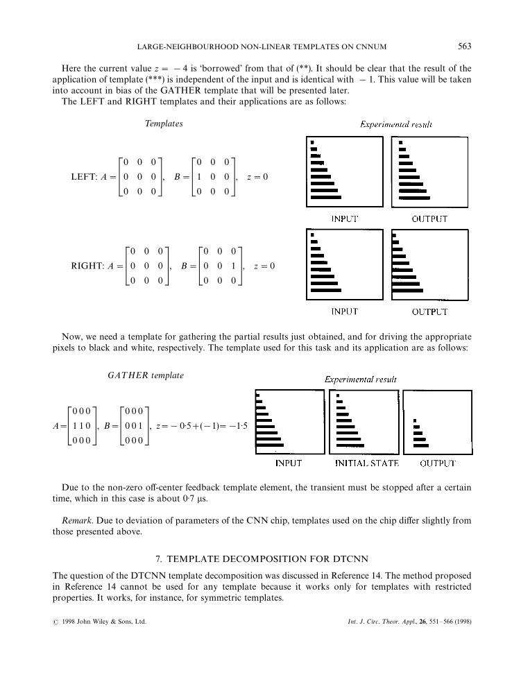
The LEFT and RIGHT templates and their applications are as follows:
¹emplates
LEFT: A"
0 0 0
0 0 0
0 0 0
, B"
0 0 0
1 0 0
0 0 0
, z"0
RIGHT: A"
0 0 0
0 0 0
0 0 0
, B"
0 0 0
0 0 1
0 0 0
, z"0
Now, we need a template for gathering the partial results just obtained, and for driving the appropriatepixels to black and white, respectively. The template used for this task and its application are as follows:
GA¹HER template
A"
0 0 0
1 1 0
0 0 0
, B"
0 0 0
0 0 1
0 0 0
, z"!0)5#(!1)"!1)5
Due to the non-zero off-center feedback template element, the transient must be stopped after a certaintime, which in this case is about 0)7 ls.
Remark. Due to deviation of parameters of the CNN chip, templates used on the chip differ slightly fromthose presented above.
7. TEMPLATE DECOMPOSITION FOR DTCNN
The question of the DTCNN template decomposition was discussed in Reference 14. The method proposedin Reference 14 cannot be used for any template because it works only for templates with restrictedproperties. It works, for instance, for symmetric templates.
LARGE-NEIGHBOURHOOD NON-LINEAR TEMPLATES ON CNNUM 563
( 1998 John Wiley & Sons, Ltd. Int. J. Circ. ¹heor. Appl., 26, 551—566 (1998)
Here we propose a general method for the DTCNN template decomposition that works for arbitrarytemplates. It is well known that a DTCNN cell has discrete time dynamics. Therefore, in such a caseit is possible to apply the template decomposition method not only for B template but also for the Atemplate. Indeed, all we have to do is, in each discrete time step t#1, to calculate the value of theterm X(t#1)"A*½(t)#B*º(t)#z, where ½(t), º(t) denote the output and input, respectively, attime t, X(t#1) denotes the state at time t#1, (A,B,z) denotes any template (both linear and non-linear).It is clear that X(t#1) can be calculated using 3]3 templates which can be obtained by applyingthe template decomposition method (see Section 6 and Reference 16). When the original template isnon-linear we need to apply the non-linear-to-linear method for each 3]3 template obtained as a result ofpartitioning.
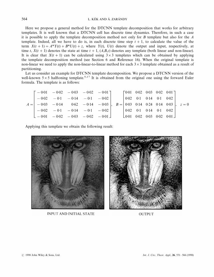
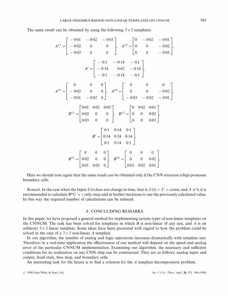
Let us consider an example for DTCNN template decomposition. We propose a DTCNN version of thewell-known 5]5 halftoning template.5,17 It is obtained from the original one using the forward Eulerformula. The template is as follows:
A"
!0)01 !0)02 !0)03 !0)02 !0)01
!0)02 !0)1 !0)14 !0)1 !0)02
!0)03 !0)14 0)62 !0)14 !0)03
!0)02 !0)1 !0)14 !0)1 !0)02
!0)01 !0)02 !0)03 !0)02 !0)01
, B"
0)01 0)02 0)03 0)02 0)01
0)02 0)1 0)14 0)1 0)02
0)03 0)14 0)24 0)14 0)03
0)02 0)1 0)14 0)1 0)02
0)01 0)02 0)03 0)02 0)01
, z"0
Applying this template we obtain the following result:
564 L. KEK AND A. ZARANDY
( 1998 John Wiley & Sons, Ltd. Int. J. Circ. ¹heor. Appl., 26, 551—566 (1998)
The same result can be obtained by using the following 3]3 templates:
A11"
!0)01 !0)02 !0)03
!0)02 0 0
!0)03 0 0
, A12"
0 !0)02 !0)01
0 0 !0)02
0 0 !0)03
,
Ac"
!0)1 !0)14 !0)1
!0)14 0)62 !0)14
!0)1 !0)14 !0)1
,
A21"
0 0 0
!0)02 0 0
!0)01 !0)02 0
, A22"
0 0 0
0 0 !0)02
!0)03 !0)02 !0)01
,
B11"
0)01 0)02 0)03
0)02 0 0
0)03 0 0
, B12"
0 0)02 0)01
0 0 0)02
0 0 0)03
,
Bc"
0)1 0)14 0)1
0)14 0)24 0)14
0)1 0)14 0)1
,
B21"
0 0 0
0)02 0 0
0)01 0)02 0
, B22"
0 0 0
0 0 0)02
0)03 0)02 0)01
,
Here we should note again that the same result can be obtained only if the CNN structure (chip) possessesboundary cells.
Remark. In the case when the Input º(t) does not change in time, that is, º(t)"º"const, and AO0, it isrecommended to calculate B*º#z only once and in further iterations to use the previously calculated value.In this way the required number of calculations can be reduced.
8. CONCLUDING REMARKS
In this paper, we have proposed a general method for implementing certain types of non-linear templates onthe CNNUM. The task has been solved for templates in which B is non-linear of any size, and A is anarbitrary 3]3 linear template. Some ideas have been presented with regard to how the problem could besolved in the case of a 3]3 non-linear A template.
In our algorithm, the number of analog and logic operations increases dramatically with template size.Therefore, in a real-time application the effectiveness of our method will depend on the speed and analogerror of the particular CNNUM implementation. Examining our algorithm, the necessary and sufficientconditions for its realization on any CNN chip can be constructed. They are as follows: analog input andoutput, fixed state, bias map, and boundary cells.
An interesting task for the future is to find a solution for the A template decomposition problem.
LARGE-NEIGHBOURHOOD NON-LINEAR TEMPLATES ON CNNUM 565
( 1998 John Wiley & Sons, Ltd. Int. J. Circ. ¹heor. Appl., 26, 551—566 (1998)
It has also been shown that certain type of non-linear templates of arbitrary size, including the A template,can be implemented on the DTCNN Universal Machine using 3]3 linear templates.
ACKNOWLEDEGMENT
The advice of T. Roska and K. Crounse, and the support of the grant T007308 of OTKA (HungarianNational Research Fund) are kindly acknowledged.
REFERENCES
1. L. O. Chua and L. Yang, ‘Cellular neural networks: theory’, IEEE ¹rans. Circuits Systems, 35, 1257—1272 (1988).2. L. O. Chua and L. Yang, ‘Cellular neural networks: applications’, IEEE ¹rans. Circuits Systems, 35, 1273—1290 (1988).3. L. O. Chua and T. Roska, ‘The CNN paradigm’, IEEE ¹rans. Circuits Systems-I, 40, 147—156, (March, 1993).4. T. Roska and L. O. Chua, ‘The CNN universal machine: an analogic array computer’, IEEE ¹rans. Circuits and Systems-II, 40,
163—173 (March, 1993).5. CADET, CSL - CNN Software Library, Version 6.4, Budapest (1995).6. CADET, ACL - Analogic CNN Language, Version 2.0, Budapest (1995).7. J. M. Cruz and L. O. Chua, ‘A CNN chip for connected component detection’, IEEE ¹rans. Circuits Systems, 38, 812—817 (1991).8. H. Harrer, J. A. Nossek, and R. Stelzl, ‘An analog implementation of Discrete-Time Cellular Neural Networks’, IEEE ¹rans. Neural
Networks, 3, 446—477 (1992).9. A. Rodriguez-Vazquez, S. Espejo, R. Dominguez-Castro, J. L. Huertas and E. Sanchez-Sinencio, ‘Current-mode techniques for the
implementation of continuous and discrete time cellular neural networks’, IEEE ¹rans. Circuits Systems, 40, 132—146 (March 1993).10. R. Dominguez-Castro, S. Espejo, A. Rodriguez-Vazquez and R. Carmona, ‘A CNN universal chip in CMOS technology’, Proc. Int.
¼orkshop on Cellular Neural Networks and their Applications (CNNA-94), Rome 1994, pp. 91—96.11. S. Espejo, R. Dominguez-Castro, A. Rodriguez-Vazquez and R. Carmona, ‘CNNUC2 User’s Guide’, Centro Nacioanal de
Microelectronica, Seville 1995.12. M. Salerno, F. Sargeni and V. Bonaiuto, ‘6]6 DPCNN: a Programmable Mixed analog-digital chip for cellular neural networks’,
Proc. Int. ¼orkshop on Cellular Neural Networks and their Applications (CNNA-96), Seville, 1996, pp. 451—456.13. J. M. Cruz and L. O. Chua, ‘Description of an Analog-Input Dual(Analog and Logic)-Output 16x16 CNN Universal Chip’,
Department of Electrical Engineering and Computer Sciences, University of California at Berkeley (1996).14. K. Slot, ‘Large-neighbourhood templates implementation in Discrete-time CNN Universal Machine with a nearest-neighbour
connection pattern’, Proc. Int. ¼orkshop on Cellular Neural Networks and their Applications (CNNA-94), Rome, 1994, pp. 213—218.15. S. Schwarz, A. Rotter and W. Mathis, ‘Composition and Decomposition of Local Operators for Cellular Neural Networks’
Kleincheubacher Berichte, Kleincheubach, Germany, 37, 253—262 (1994).16. K. R. Crounse and L. O. Chua, ‘Arbitrary spatial convolution via CNN universal machine with 3]3 templates: methods and issues’,
Memorandum No. UCB/ERL M96/5 (1996).17. K. R. Crounse, T. Roska, and L. O. Chua, ‘Image halftoning with cellular neural networks’, IEEE ¹rans. Circuits Systems-II. Analog
Digital Signal Process., 40, 267—283 (April 1993).
566 L. KEK AND A. ZARANDY
( 1998 John Wiley & Sons, Ltd. Int. J. Circ. ¹heor. Appl., 26, 551—566 (1998)