Embed Size (px)
Citation preview
Page 113 www.ijiras.com | Email: [email protected]
International Journal of Innovative Research and Advanced Studies (IJIRAS)
Volume 4 Issue 10, October 2017
ISSN: 2394-4404
Implementation Of Five-Level Cascaded H-Bridge Inverter For
Single-Phase Ac Induction Motor Using Proportional-Integral
Controller
C. Ezugwu
Department of Electrical & Electronics Engineering
Technology, School of Engineering Technology, Federal
Polytechnic Nasarawa (FPN), Nasarawa State, Nigeria
J.U. Agber
C.O. Onah
Department of Electrical/Electronic Engineering University
of Agriculture, Makurdi, Benue State, Nigeria
I. INTRODUCTION
The improvement in power electronics and semiconductor
technology has brought about the development of high power
and high-speed semiconductor devices in order to achieve a
smooth uninterrupted and step less variation in motor speed.
Applications of solid state converters/inverters for adjustable
speed induction motor drive are wide spread in
electromechanical systems for a large spectrum of industrial
systems [1, 3, 11].
The classical two level inverter exhibits many problems
when used in high power applications. The poor quality of
output current and voltage of an induction motor fed by a
conventional two-level inverter is due to the presence of
harmonic content. The presence of significant amount of
harmonic makes the motor to undergo severe torque pulsation,
especially at low speed, which manifests them in cogging of
the shaft. It will also cause undesired motor heating and
electromagnetic interference. Minimization in harmonics calls
for large size filter, resulting in increased size and the cost of
the system. The advancements in the field of power
electronics and microelectronics made it possible to reduce the
magnitude of harmonics with multilevel inverters, in which
the number of levels of the inverters is increased rather than
increasing the size of the filters [2-3, 11].
II. MULTILEVEL INVERTER
Multilevel inverters use series-connected semi-conductors
to increase a inverter’s voltage rating (and thus its power
level) well beyond the capacity of individual devices while
Abstract: Renewable power generation (RPG) is a promising alternative source of energy and has many advantages
than the other energy sources. In renewable power generation, multilevel inverters play a crucial role in power
conversion. The three different topologies, diode-clamped (neutral-point clamped) inverter, capacitor-clamped (flying
capacitor) inverter, and cascaded H-bridge multilevel inverter, are widely used in these multilevel inverters. Among the
three topologies, cascaded H-bridge multilevel inverter is more suitable for renewable energy source such as in
photovoltaic applications since each photovoltaic array can act as a separate direct current source for each H-bridge
module. In this paper, a single-phase cascaded H-bridge five-level inverter for single-phase ac induction motor connected
12V battery system using proportional–integral controller is presented. Sinusoidal pulse width modulation technique was
used for eliminating the harmonic distortion. The performance of single-phase cascaded H-bridge five-level inverter with
respect to harmonic content and number of switches is simulated using MATLAB/Simulink. A hardware prototype is
developed to verify the performance of the developed system. The results of hardware are compared with the simulation
results. The proposed system offers improved performance over conventional two-level inverters.
Keywords: H-bridge, RPG, MATLAB, Five levels, Integral Controller
Page 114 www.ijiras.com | Email: [email protected]
International Journal of Innovative Research and Advanced Studies (IJIRAS)
Volume 4 Issue 10, October 2017
ISSN: 2394-4404
still limiting each device’s voltage stress to below its
individual rating. Furthermore, since these converters also
create several levels of switched output voltage, multilevel
inverters will significantly reduce the magnitude of harmonics
and increases the output voltage and power without the use of
a step-up transformer [13]. The general function is to
synthesize the desired voltage from several DC sources. The
AC terminal voltages of each bridge are connected in series
and can generate three different output voltages levels namely
0, + Vdc and –Vdc [3].
There are different types of multilevel inverters, but three
of them are outlined in this paper and are of great importance
in industrial applications; capacitor clamped multilevel
inverter, diode clamped multilevel inverter and cascaded H-
bridge multilevel inverter with separate DC sources [7].
Proper switching of switches permits the addition of capacitor
voltages in the output port and results in a generation of high
voltages without stressing the semiconductors [5, 9]. This
study deals with simulation and implementation of single
phase 5 levels cascaded H-bridge inverter for split-phase
single-phase AC induction motor.
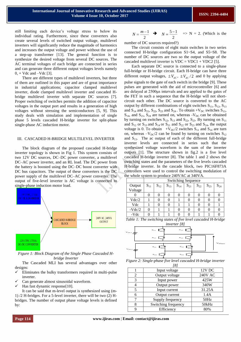
III. CASCADED H-BRIDGE MULTILEVEL INVERTER
The block diagram of the proposed cascaded H-bridge
inverter topology is shown in Fig 1. This system consists of
two 12V DC sources, DC–DC power converter, a multilevel
DC–AC power inverter, and an RL load. The DC power from
the battery is boosted using the DC–DC boost converter with
DC bus capacitors. The output of these converters is the DC
power supply of the multilevel DC–AC power converter. The
output of five-level inverter is AC voltage is connected to
single-phase induction motor load.
12V-170V ,170VA
DC-DC CONVERTER
12V-170V ,170VA
DC-DC CONVERTER
CASCADED H-BRIDGE
BLOCK
240V AC ,340VA
OUTPUT
Figure 1: Block Diagram of the Single Phase Cascaded H-
bridge Inverter
The Cascaded MLI has several advantages over other
designs:
Eliminates the bulky transformers required in multi-pulse
inverter.
Can generate almost sinusoidal waveform.
Has fast dynamic response[10].
It can be said that m-level output is synthesized using (m-
1) /2 H-bridges. For a 5-level inverter, there will be two (2) H-
bridges. The number of output phase voltage levels is defined
by:
2
1
mN
2
15N => N = 2. (Which is the
number of DC sources required?)
The circuit consists of eight main switches in two series
connected H-bridge configuration S1~S4, and S5~S8. The
number of DC sources are two so the output voltage of the
cascaded multilevel inverter is VDC = VDC1 + VDC2 [5].
Each separate DC source is connected to a single-phase
full-bridge or H-bridge circuit. Each H-bridge can have three
different output voltages, dCV , 2/dCV and 0 by applying
pulse signals to the gate of each switch in the bridge [9]. These
pulses are generated with the aid of microcontroller [6] and
are delayed at 2500μs intervals and are applied to the gates of
the FET in such a sequence that the H-bridge will not short-
circuit each other. The DC source is converted to the AC
output by different combinations of eight switches S11, S12, S13
and S14 and S21, S22, S23 and S24 . To obtain +VDC switches S11,
S14, and S21, S24 are turned on, whereas -VDC can be obtained
by turning on switches S12, S13 and S22, S23. By turning on S11
and S12 or S13 and S14 or S21 and S22 or S23 and S24, the output
voltage is 0. To obtain +VDC/2 switches S11 and S14 are turn
on, whereas –VDC/2 can be found by turning on switches S12
and S13. The ac output of each of the different full-bridge
inverter levels are connected in series such that the
synthesized voltage waveform is the sum of the inverter
outputs [1]. The structure shown in fig.2 is a five level
cascaded H-bridge inverter [8]. The table 1 and 2 shows the
switching states and the parameters of the five levels cascaded
H-bridge inverter. In the cascade block, two PIC16F873A
controllers were used to control the switching modulation of
the whole system to produce 240VAC at 340VA.
Switching Sequence
Output
Voltage
S11 S12 S13 S14 S21 S22 S23 S24
0 0 0 0 0 0 0 0 0
Vdc/2 1 0 0 1 0 0 0 0
Vdc 1 0 0 1 1 0 0 1
-Vdc/2 0 1 1 0 0 0 0 0
-Vdc 0 1 1 0 0 1 1 0
Table 1: The switching states of five level cascaded H-bridge
inverter [8]
VDC1
S11
S13
S12
S14
VDC2
S21
S23
S22
S24
VPhase
Figure 2: Single-phase five level cascaded H-bridge inverter
[8]
1 Input voltage 12V DC
2 Output voltage 240V AC
3 Input power 425W
4 Output power 340W
5 Input current 31.25A
6 Output current 1.4A
7 Supply frequency 50Hz
8 Switching frequency 50kHz
9 Efficiency 80%
Page 115 www.ijiras.com | Email: [email protected]
International Journal of Innovative Research and Advanced Studies (IJIRAS)
Volume 4 Issue 10, October 2017
ISSN: 2394-4404
Table 2: shows the Parameters of the Cascaded H-bridge
inverter
IV. CONTROL SCHEME
PWM technique is extensively used for eliminating
harmful low-order harmonics in inverters. In PWM control,
the inverter switches are turned ON and OFF several times
during a half cycle and output voltage is controlled by varying
the pulse width [12]. Several modulation strategies have been
developed for multilevel inverters such as Selective harmonic
elimination pulse- width modulation (SHE-PWM), Space
vector pulse- width modulation (SVPWM) and Sinusoidal
pulse –width modulation (SPWM). The most commonly used
is the SPWM technique [2].
In SPWM, instead of maintaining the width of all pulses
the same as in the case of multiple PWM, the width of each is
varied in proportion to the amplitude of a sine wave evaluated
at the same pulse. The distortion is reduced significantly
compared to multiple PWM. The fig.3 shows the basic
working of PWM (Pulse Width Modulation).Two different
signals i.e. low-level signal & high-frequency carrier signal
are compared together through a Relational Operator
(MATLAB). It will compare both the waveforms and gives
the result with the condition provided. It will consider one
reference signal and other as the carrier signal [6].
The gating pulses are shown in Fig 4. The SPWM is the
method to be used in simulation and implementation due to its
many benefits, such as easy implementation, lower harmonic
outputs, and low switching losses.
Figure 3: Basic block diagram of PWM [4]
t
VCONTROLVTRI
t
VAO(t)
Vd/2
-Vd/2
Figure 4: Sinusoidal Pulse width modulation [5]
V. SIMULATION
The MATLAB/SIMULINK was used to simulate 5-level
inverter system. A split-phase single-phase induction motor
drive was used in the MATLAB environment, where all
parameters and blocks are modeled based on basic concept
explained above. One of the key features is that it allows the
user to simulate the design over a specified period. This way it
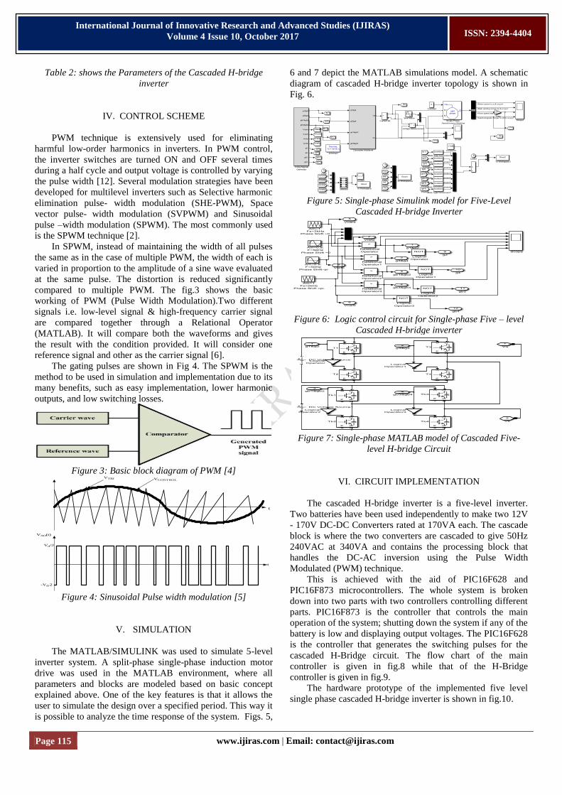
is possible to analyze the time response of the system. Figs. 5,
6 and 7 depict the MATLAB simulations model. A schematic
diagram of cascaded H-bridge inverter topology is shown in
Fig. 6.
Figure 5: Single-phase Simulink model for Five-Level
Cascaded H-bridge Inverter
Figure 6: Logic control circuit for Single-phase Five – level
Cascaded H-bridge inverter
Figure 7: Single-phase MATLAB model of Cascaded Five-
level H-bridge Circuit
VI. CIRCUIT IMPLEMENTATION
The cascaded H-bridge inverter is a five-level inverter.
Two batteries have been used independently to make two 12V
- 170V DC-DC Converters rated at 170VA each. The cascade
block is where the two converters are cascaded to give 50Hz
240VAC at 340VA and contains the processing block that
handles the DC-AC inversion using the Pulse Width
Modulated (PWM) technique.
This is achieved with the aid of PIC16F628 and
PIC16F873 microcontrollers. The whole system is broken
down into two parts with two controllers controlling different
parts. PIC16F873 is the controller that controls the main
operation of the system; shutting down the system if any of the
battery is low and displaying output voltages. The PIC16F628
is the controller that generates the switching pulses for the
cascaded H-Bridge circuit. The flow chart of the main
controller is given in fig.8 while that of the H-Bridge
controller is given in fig.9.
The hardware prototype of the implemented five level
single phase cascaded H-bridge inverter is shown in fig.10.
Page 116 www.ijiras.com | Email: [email protected]
International Journal of Innovative Research and Advanced Studies (IJIRAS)
Volume 4 Issue 10, October 2017
ISSN: 2394-4404
START
CONFIGURE INPUT/OUTPUT
INITIALIZE LCD
INITIALIZE ADC
READ INPUT ON
THE ADC PORTS BATTERY LOW
SHUT DOWN
DISPLAY OUTPUT
VALUES
COMPARE READ
VALUES TO SET
POINT BATTERY
VALUES
YES
Figure 8: Algorithm for the main controller- PIC 16F873
START
CONFIGURE INPUT/OUTPUT
EXECUTE LEVEL 1
DELAY 2.5mS
EXECUTE LEVEL 8
DELAY 2.5mS Figure 9: Algorithm for the two H-bridge controllers – PIC 16
F628
Figure 10: Hardware Prototype of Single-Phase Five Level
Cascaded H-bridge Inverter
VII. SIMULATION RESULTS
Figs. 11, 12, 13 ,14 and 15 shows the reference and
carrier signals, gating signals, output current and voltage
waveforms, rotor speed and electromagnetic torque
waveforms. Also, the Fast Fourier Transform (FFT) plot of the
five levels H-bridge inverter to analyse Total harmonic
Distortion at modulation index of 0.8 is shown in fig.16. The
table 3 is the table of THD voltages and percentage THDs at
different modulation indexes of 1.0, 0.9, 0.7, 0.6,0.5,0.4, 0.3,
0.2, and 0.1. The bar chart plot of THD voltages and
percentage THDs at different modulation indexes are shown in
fig.17 and 18 respectively.
VIII. DISCUSSION OF RESULT FROM SIMULATION
The simulated results are shown in fig.18-23. Fig. 11
shows the reference and carrier signal at 0.8 modulation index,
50Hz and 2kHz carrier signals modulated to generate the
pulses at fig.12. This pulse in fig.12 is the gating signals for
the inverter power switches. It is used to trigger each gate of
the eight switches at different intervals to generate a stair-case
current and voltage waveforms. Fig.13 shows the five level
output current and voltage waveforms of amplitude 42.5A and
240V of the inverter which is used to feed the load. The
current waveforms are closed to sinusoidal waveform.
The speed versus the simulation time of the motor is
shown in fig.14. It is observed that the speed rises linearly
from zero seconds to 0.92s and stall at about 1200 rev/min in
0.928s. This is the point the centrifugal switch open the circuit
of the starting winding, the motor operates on a single phase
supply. The speed rises to a steady state at 1500 rev/min in
1.2s simulation time. Fig.15 is the electromagnetic torque
plots versus time of the motor. At the point of starting the
torque waveforms oscillate from zero to a maximum of 10Nm
at 0.11s and decreases to 6Nm at 0.2s. At the point of 0.2s, it
decreases to 2Nm at 0.216s and rises linearly to 10Nm at 0.92s
and stalls at 0.928s to 6Nm and then maintains running torque
of 4Nm at 1.2s at its steady state of 1500rpm. The speed and
torque ripples are less and have a better dynamic response.
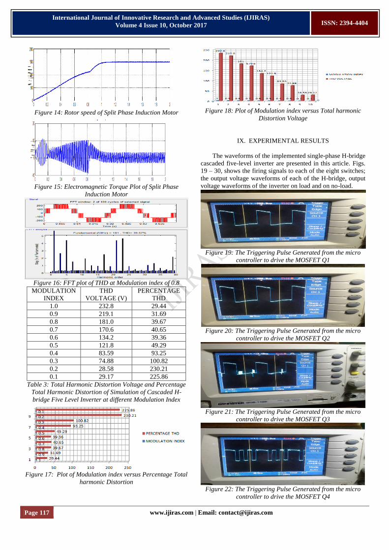
The total harmonic distortion is analyzed. It is observed
that the percentage THD at 0.8 modulation index is 39.67% as
shown in fig. 16 of FFT analysis. The bar chart of modulation
index versus percentage THD and THD voltages are plotted
from table 3 as shown in fig.17 and 18 respectively. It is
observed that the higher the modulation index, the better the
output voltage wave form approximate sinusoidal wave
without distortions. Therefore, the lower percentage total
harmonic distortions(THD) is indicating a reduction in peak
current, heating, emission and core loss in motor.
Figure 11: Reference and carrier signals
Figure 12: Gating or Firing Signals for the Inverter Power
Switches
Figure 13: Output current and voltage waveforms of the
inverter Simulation
Page 117 www.ijiras.com | Email: [email protected]
International Journal of Innovative Research and Advanced Studies (IJIRAS)
Volume 4 Issue 10, October 2017
ISSN: 2394-4404
Figure 14: Rotor speed of Split Phase Induction Motor
Figure 15: Electromagnetic Torque Plot of Split Phase
Induction Motor
Figure 16: FFT plot of THD at Modulation index of 0.8
MODULATION
INDEX
THD
VOLTAGE (V)
PERCENTAGE
THD
1.0 232.8 29.44
0.9 219.1 31.69
0.8 181.0 39.67
0.7 170.6 40.65
0.6 134.2 39.36
0.5 121.8 49.29
0.4 83.59 93.25
0.3 74.88 100.82
0.2 28.58 230.21
0.1 29.17 225.86
Table 3: Total Harmonic Distortion Voltage and Percentage
Total Harmonic Distortion of Simulation of Cascaded H-
bridge Five Level Inverter at different Modulation Index
Figure 17: Plot of Modulation index versus Percentage Total
harmonic Distortion
Figure 18: Plot of Modulation index versus Total harmonic
Distortion Voltage
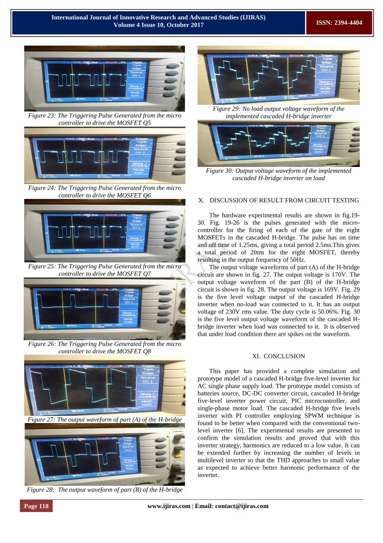
IX. EXPERIMENTAL RESULTS
The waveforms of the implemented single-phase H-bridge
cascaded five-level inverter are presented in this article. Figs.
19 – 30, shows the firing signals to each of the eight switches;
the output voltage waveforms of each of the H-bridge, output
voltage waveforms of the inverter on load and on no-load.
Figure 19: The Triggering Pulse Generated from the micro
controller to drive the MOSFET Q1
Figure 20: The Triggering Pulse Generated from the micro
controller to drive the MOSFET Q2
Figure 21: The Triggering Pulse Generated from the micro
controller to drive the MOSFET Q3
Figure 22: The Triggering Pulse Generated from the micro
controller to drive the MOSFET Q4
Page 118 www.ijiras.com | Email: [email protected]
International Journal of Innovative Research and Advanced Studies (IJIRAS)
Volume 4 Issue 10, October 2017
ISSN: 2394-4404
Figure 23: The Triggering Pulse Generated from the micro
controller to drive the MOSFET Q5
Figure 24: The Triggering Pulse Generated from the micro
controller to drive the MOSFET Q6
Figure 25: The Triggering Pulse Generated from the micro
controller to drive the MOSFET Q7
Figure 26: The Triggering Pulse Generated from the micro
controller to drive the MOSFET Q8
Figure 27: The output waveform of part (A) of the H-bridge
Figure 28: The output waveform of part (B) of the H-bridge
Figure 29: No load output voltage waveform of the
implemented cascaded H-bridge inverter
Figure 30: Output voltage waveform of the implemented
cascaded H-bridge inverter on load
X. DISCUSSION OF RESULT FROM CIRCUIT TESTING
The hardware experimental results are shown in fig.19-
30. Fig. 19-26 is the pulses generated with the micro-
controller for the firing of each of the gate of the eight
MOSFETs in the cascaded H-bridge. The pulse has on time
and off time of 1.25ms, giving a total period 2.5ms.This gives
a total period of 20ms for the eight MOSFET, thereby
resulting in the output frequency of 50Hz.
The output voltage waveforms of part (A) of the H-bridge
circuit are shown in fig. 27. The output voltage is 170V. The
output voltage waveform of the part (B) of the H-bridge
circuit is shown in fig. 28. The output voltage is 169V. Fig. 29
is the five level voltage output of the cascaded H-bridge
inverter when no-load was connected to it. It has an output
voltage of 230V rms value. The duty cycle is 50.06%. Fig. 30
is the five level output voltage waveform of the cascaded H-
bridge inverter when load was connected to it. It is observed
that under load condition there are spikes on the waveform.
XI. CONCLUSION
This paper has provided a complete simulation and
prototype model of a cascaded H-bridge five-level inverter for
AC single phase supply load. The prototype model consists of
batteries source, DC-DC converter circuit, cascaded H-bridge
five-level inverter power circuit, PIC microcontroller, and
single-phase motor load. The cascaded H-bridge five levels
inverter with PI controller employing SPWM technique is
found to be better when compared with the conventional two-
level inverter [6]. The experimental results are presented to
confirm the simulation results and proved that with this
inverter strategy, harmonics are reduced to a low value. It can
be extended further by increasing the number of levels in
multilevel inverter so that the THD approaches to small value
as expected to achieve better harmonic performance of the
inverter.
Page 119 www.ijiras.com | Email: [email protected]
International Journal of Innovative Research and Advanced Studies (IJIRAS)
Volume 4 Issue 10, October 2017
ISSN: 2394-4404
REFERENCES
[1] Amarita.M.V, Eldhose K.A & Ninu.J. (2014). Single
phase inverter for ac motor. International Journal of
Engineering Research and Development, Volume 9, Issue
11.
[2] Colak.I. etal. (2010). Review of Multilevel Voltage
Source Inverter Topologies and Control Scheme. Energy
Conversion Management, doi:10.1016/j.enconman.
[3] Diyoke.G, Offiong.A, Nnadi.C. (2014). Design and
Simulation of Single-Phase Three-Level, Four-Level and
Five-level Inverter Fed Asynchronous Motor Drive with
Diode Clamped Topology. Publisher international journal
Engineering Trends and Technology (IJETT) volume 12.
[4] Jatin A. P and Hardik H.R (2015). Design of Sinusoidal
Pulse Width Modulation Inverter. International Journal
for Technological Research in Engineering Volume 2,
Issue 8, ISSN: 2347 – 4718.
[5] Manasa etal. (2012). Design and Simulation of three-
phase five level and seven level inverter fed induction
motor drive with two cascaded H-bridge configuration.
International Journal of Electrical/Electronic Engineering
(IJEEE), ISSN (PRINT) 2231-5284, Volume1 Iss. 4.
[6] Melba. M .P .R & Sivagama .S.M. S (2016). Cascaded H-
Bridge Five-Level Inverter for Grid-Connected
Photovoltaic System Using Proportional–Integral
Controller. Measurement and Control, Vol.49(1) 33–41
[7] Meynard. A and Foch.H, (1992). ”Multilevel Conversion:
High Voltage Choppers and Voltage Source Inverters” in
Proc. IEEE PESC’ 92, pp. 397-403
[8] Prasad J. G. R. and Reddy K. R. (2012). Design and
Simulation of Cascaded H-Bridge Multilevel Inverter
Based DSTATCOM. International Journal of Engineering
Trends and Technology- Volume3Issue1- 2012.
[9] Rashid.M, Abedi .M, Gharehpetian. (2013). Comparison
between 7-level cascaded diode-clamped multilevel
inverters for feeding induction motor. Research Journal of
AppliedScience, Engineering and Technology, Volume
6, Issue 6, pp 936-942.
[10] Shaik .N .V & Kalluri .V (2017). Modeling and Analyses
of Cascaded H-Bridge Five Level Multilevel Converter
for Micro Grid Application. International Journal of
Advanced Scientific Technologies, Engineering and
Management Sciences (IJASTEMS-ISSN: 2454-356X)
Volume.3, Special Issue.1, May. 2017.
[11] Senthkumar. P, Balachandran. M, Subramaniam. N.P
(2013) Cascaded H-bridge Multilevel Inverter Using
Sinusoidal Pulse Width Modulation (SPWM).
International Journal of Advanced Research in
Engineering and Applied Sciences. Volume 2 No.1.
[12] Suganyadevi.D, Rekha.K, Iswarya.M. (2014). Harmonic
reduction in induction motor: multilevel inverter.
Department of power Electronics, and Drives, P.A
College of Engineering and Technology, Pollachi
(Tamilnadu), India, Volume 2.
[13] Vinod K.P, Santtosh K.C, Ramesh K.R. (2013). Single-
phase cascaded multilevel inverter using Multi-carrier
PWM technique. Asia Research Publishing Network
Journal of Engineering and Applied Sciences, Volume 8,
No.10.