Embed Size (px)
Citation preview
7/24/2019 Implementation of a Digital Communucation System A
http://slidepdf.com/reader/full/implementation-of-a-digital-communucation-system-a 1/98
IMPLEMENTATION OF A DIGITAL
COMMUNUCATION SYSTEM
MOHAMMAD TAHA HAMID MURAD SODQI H. AYYASH
Supervised by
Dr. ALLAM MOUSA
Electrical Engineering DepartmentAn-Najah National University
2011

7/24/2019 Implementation of a Digital Communucation System A
http://slidepdf.com/reader/full/implementation-of-a-digital-communucation-system-a 2/98
2
IMPLEMENTATION OF A DIGITAL
COMMUNUCATION SYSTEM
MOHAMMAD TAHA HAMID MURAD SODQI AYYASH
[email protected] [email protected]
Supervised by
Dr. ALLAM MOUSA
A Thesis presented to the Electrical Engineering Department of An-Najah National University inthe fulfillments of partial requirements of the B.Sc. degree in Electrical Engineering.
Department of Electrical EngineeringFaculty of Engineering
An-Najah National University
2011

7/24/2019 Implementation of a Digital Communucation System A
http://slidepdf.com/reader/full/implementation-of-a-digital-communucation-system-a 3/98
3
ABSTRACT
The implementation of the digital communication system is important for the study, analysis,test and development of the performance of the system, in this project we introduce two parts tocarry out the implementation, the theoretical part and it is concerned with the study andanalysis of the algorithms in source coding, channel coding and data security represented incryptography and steganography. the second part is the MATLAB implementations, simulationsand analysis, the adopted algorithms for the implementation are Huffman, BWT compression,Run-Length coding and decoding, for lossless source coding, BCH coding and decoding, for
forward error correction, advanced encryption standard AES with 128-bit cipher key with second protection layer of steganography for data security, the performance was simulated and testedunder the AWGN channel with M-PSK digital modulation.

7/24/2019 Implementation of a Digital Communucation System A
http://slidepdf.com/reader/full/implementation-of-a-digital-communucation-system-a 4/98
4
ACKNOWLEDGMENT
We wish to express our appreciation of the assistance given us by the Dr.Allam Mousa, thesupervisor of our project, Department of Electrical Engineering, An-Najah National University.

7/24/2019 Implementation of a Digital Communucation System A
http://slidepdf.com/reader/full/implementation-of-a-digital-communucation-system-a 5/98
5
Table of Contents
Chapter One
Source Coding.......................................................................................................................................................... 10
Introduction ........................................................................................................................................................ 11
Entropy and conditional Entropy .......................................................................................................... 12
Conditional Entropy and Mutual Information: ................................................................................ 13
Lossless Coding Techniques .............................................................................................................................. 15
Entropy Coding .................................................................................................................................................. 16
Shannon-Fano Coding: ............................................................................................................................... 16
Huffman Coding ............................................................................................................................................ 16
Upper Bound for the Huffman Code ..................................................................................................... 19
And Coding in Blocks .................................................................................................................................. 19
The Burrows- Wheeler Transform ‘‘BWT’’ .............................................................................................. 24
BWT Algorithm Description .................................................................................................................... 24
Move-To-Front Transform ....................................................................................................................... 25
The Decoding of Burrows-Wheeler Transform ............................................................................... 28
Decoding of Move-To-Front Transform ............................................................................................. 31
Chapter TwoChannel Coding Overview .................................................................................................................................. 33
Channel Capacity ............................................................................................................................................... 35
Capacity for Additive White Gaussian Noise Channel ................................................................... 38
Block Channel Coding ..................................................................................................................................... 39
Mathematical Related Concepts ............................................................................................................. 40
Encoding of BCH code ................................................................................................................................ 42
Decoding of BCH Codes.............................................................................................................................. 46
Chapter Three
Encryption ................................................................................................................................................................ 52
Overview .............................................................................................................................................................. 52
Rijndael Algorithm: ..................................................................................................................................... 53
Encryption process ...................................................................................................................................... 59

7/24/2019 Implementation of a Digital Communucation System A
http://slidepdf.com/reader/full/implementation-of-a-digital-communucation-system-a 6/98
6
Steganography ................................................................................................................................................... 63
Chapter Four
System Performance Simulations ................................................................................................................... 65
The Source Coder .............................................................................................................................................. 65
The output of source coder ........................................................................................................................... 66
The Channel Coder and Channel................................................................................................................. 67
The Encryption-Decryption Process ......................................................................................................... 69
The Steganography Process ........................................................................................................................ 71
System Implementation ...................................................................................................................................... 72
The MATLAB Functions ...................................................................................................................................... 74
The Source Coding and Decoding Functions .............................................................................................. 74
Data Analysis with Entropy Function ....................................................................................................... 74
Run-Length Encoder and Decoder ............................................................................................................. 75
Huffman Encoder & Decoder ....................................................................................................................... 77
BWT encoder & decoder ................................................................................................................................ 79
The Channel Coding and Decoding Function ............................................................................................. 83
The Encryption Functions ............................................................................................................................. 85
Steganography ................................................................................................................................................... 92
References ................................................................................................................................................................ 98

7/24/2019 Implementation of a Digital Communucation System A
http://slidepdf.com/reader/full/implementation-of-a-digital-communucation-system-a 7/98
7
Introduction
The project aims at the implementation of the following digital communication system startingfrom the data processing with digital input data. The figure below shows a block diagram of a
digital communication system with two possibilities for the input data that may be an analog ordigital data
The brief overview for the system parts and its parts is described as follows:
Source coding
The data compression or source coding is the process of encoding information using fewer bits(or other information-bearing units) than an unencoded representation would use, by removingthe redundancy and we can remove it until limit defined as entropy through use of specificencoding schemes. For example Huffman BWT. The Function of source coding is to reduce thesize of information that will be transmitted to maintain the resources. BW , power and spacedata storage. The first chapter introduces the BWT compassion which employs Huffman coding, MTFtransforms ,BW transforms.
Block diagram of Digital communication system

7/24/2019 Implementation of a Digital Communucation System A
http://slidepdf.com/reader/full/implementation-of-a-digital-communucation-system-a 8/98
8
Channel coding
It is the addition of redundancy on the original input bit steam taking the channel capacity intoconsideration it is functions to ensure that the signal transmitted is recovered with very lowprobability of error at the destination and usually designed to make error-correction possible . The BCH forward error correction algorithm is adopted and it is discussed in the second chapter
Encryption:
It is the process of transforming information(referred to as plaintext) using an algorithm(calledcipher) to make it unreadable to anyone except those possessing special knowledge, usuallyreferred to as a key. It is used to protect the information (privacy), authentication(verifying themessage origin) and Integrity(establishing that a received message has not altered).Anotherlayer maybe added to conceal the encrypted data which is the steganography .The third chapter is a description of AES in order to implement Rijndael encryption algorithm .
The Channel
The channel is the media that the signal will propagate into to the receiving part of the systemthis channel introduces an error to the signal. it is limited by a specific bandwidth andconsequently a specific capacity. The AWGN channel is adopted with digital M-PSK modulateddata.
The last chapter is the MATLAB implementation of the system with simulations and analysis thatare needed to measure the performance of the system.

7/24/2019 Implementation of a Digital Communucation System A
http://slidepdf.com/reader/full/implementation-of-a-digital-communucation-system-a 9/98
9
Chapter One
SOURCECODINGImplementation of Source Coding and
DecodingIn this chapter analysis and implementation of Entropy coding such as Huffman coding ,and other coding Techniques like Run Length Coding , MTF transform and BWT as anefficient text-coding technique

7/24/2019 Implementation of a Digital Communucation System A
http://slidepdf.com/reader/full/implementation-of-a-digital-communucation-system-a 10/98
10
Lossless Source Coding Algorithms
Entropy Encoding
HuffmanCoding
AdaptiveHuffman
Shannon-Fano
Arithmetic
coding
Golomb
coding
Dictionarycoders
Lempel-ZivAlgorithms
LZ77 LZ78
Other Ecoding Algorithms
Datadeduplication
Run-length
encoding
Burrows –Wheeler
transform
Context
mixing
DynamicMarkovCompres
sion
Source Coding
In this chapter the lossless source coding techniques are to be studied and analyzed in order tobe implemented.
The lossless coding techniques is summarized in this chart
This chapter is a study, analysis and implementation of the lossless source coding techniques,the first algorithm is the Huffman Coding which is chosen since it has an acceptable codeefficiency and performance for all types of files. The second is the Burrows –Wheeler transformwhich is more efficient compression coding for text files. The third is the run length coding.

7/24/2019 Implementation of a Digital Communucation System A
http://slidepdf.com/reader/full/implementation-of-a-digital-communucation-system-a 11/98
11
IntroductionA code is a mapping of discrete of set of symbols to finite binary sequences,Data compression or Source coding is the process of encoding information using fewer bits thanan unecoded representation, by removing the redundancy and we can remove it until limitdefined as entropy.
We have two kinds of source coding ,lossless source coding by which the data can be decoded toform exactly same bits can be achieved by moderate compression ( e.g.: 2:1 ) this type is used in“ZIP” and important applicationsin medical images that’s we can’t accept any error in it. On theother hand we have lossy coding which is Method for representing discrete-space signals withminimum Distortion. Decompressed image is visually similar but has high compression ratio ( ex:20:1 ),this type is used in JPEG and MPEG .
According of the output of the coder we have Variable length coding that is compressed anddecompressed with zero error (lossless data compression) and the each symbol representationof bits depends on the probability (ex: Huffman ,Shannon-Fano,…) and the second one is fixedlength code which all symbol have the same codeword length independent of theprobability(Lempel-Ziv).
A Prefix Code is a specific type of uniquely decodable code in which no code is a prefix ofanother code, as shown with a source
Symbol Codeword
S0 0S1 10S2 110S3 111
Run length coding is very simple code that is orders the same data value occurs in manyrepeated data elements are stored as a single data value and count, rather than as the originalrun
For example if we have data like this (0000000111111111000000) more efficient to representthe data like this ( 07 19 06 ).
Efficiency parameter (η ) for a code is very important to know which code is more efficient bythis equation below

7/24/2019 Implementation of a Digital Communucation System A
http://slidepdf.com/reader/full/implementation-of-a-digital-communucation-system-a 12/98
12
0 0.1 0.2 0.3 0.4 0.5 0.6 0.7 0.8 0.9 10
0.1
0.2
0.3
0.4
0.5
0.6
0.7
0.8
0.9
1
Techniques we will cover in details in this section, Huffman coding, Shannon-Fano and BWTtransform & compression.
Entropy and conditional Entropy
The basic definition of the Entropy is a measure of the source information depends on theprobabilities of its data symbols .
The information of a single event or message‘ I ’ that any data contains is defined as the base 2logarithm of its probability‘p’ as follows
And the entropy ‘H’ is the negative of the information
For a data of many symbols its entropy is defined as the average entropy of all elements
For a two random variables that take two probabilities of P and 1-P the entropy is as thefollowing :
Probability
E n t r o p y o
f a
B i n a r y s o u r c e
Figure 1: P vs. H for Two Symbols –Data (Binary Source Of Information )

7/24/2019 Implementation of a Digital Communucation System A
http://slidepdf.com/reader/full/implementation-of-a-digital-communucation-system-a 13/98
13
Conditional Entropy and Mutual Information:
If X and Y are two variables, and if x and y are correlated, theirMutual Information is Theaverage information that Y gives about X .
And their entropy is a conditional entropy and it is given as the entropy of X given Y :
The Mutual information between X and Y is
This equation describes that the mutual information is the reduction in uncertainty of X given Y .
In order to implement source coding techniques, the following files are to be used as an input ofthe encoders , the files are analyzed by measuring its size before the compression and itsentropy in bits per symbol and then the output file size , the results are for samples of :
Text Files
# size beforebytes(txt)
size afterbytes
entropy
1 1.14 k 588 4.14862 30.5k 13.14k 4.1793 56.9k 24.28k 4.1554 79.6k 34.13k 4.1575 183k 78.8k 4.1626

7/24/2019 Implementation of a Digital Communucation System A
http://slidepdf.com/reader/full/implementation-of-a-digital-communucation-system-a 14/98
14
Images TIF(Tagged Image File)
Speech Files
Images JPG
# Size Before
Bytes
Size After
Bytes
Entropy
1 2.25M 1.96M 6.5552 2.26M 2.187M 7.743 28.8M 27.515M 7.854 264K 230.2K 7.575 510K 413.66K 6.636 916K 876.8K 7.777 1.38M 1.285M 7.55
#Speechbytes
Speech EntropyBit/symbol
1 286K 13.07522 160.6K 13.11373 59K 13.244 78.7K 14.115 52K 13.176 61K 12.87 23K 12.56
#Image size
MbSpeech Entropy
Bit/symbol
1 4.82 7.91772 3.41 7.70873 0.091 7.67224 0.838 7.311

7/24/2019 Implementation of a Digital Communucation System A
http://slidepdf.com/reader/full/implementation-of-a-digital-communucation-system-a 15/98
15
It appears that the file size and its entropy are independent since the entropy depends on theprobability of the source symbols , but it is different between the different types of files .
The entropy will affect the size at the output of the encoder and it will be different for eachcoding technique.
Lossless Coding Techniques
The Lossless Data Compression technique recommended preserves the source data accuracy byremoving redundancy from the application source data. In the decompression processes theoriginal source data is reconstructed from the compressed data by restoring the removedredundancy ,The reconstructed data is an exact of the original source data . The motivation forusing compression is to Save storage space or bandwidth.
The performance of the data compression algorithm is independent of where it is applied , itmay be necessary to rearrange the data into appropriate sequence before applying the datacompression algorithm. The purpose of rearranging data is to improve the compression ratio.
After compression has been performed, the resulting variable-length data structure is thenPacketized(compressed file). The packets containing compressed data should be transportedthrough a channel communication link from the source to the receiver . The contents of thepackets are then extracted and data about algorithm are provided to the receiver in order tobe decompressed.
One of the Parameters that are needed to check for any algorithm ,compression ratio is theratio between the size of the compressed file and the size of the source file.
Compression factor is the inverse of the compression ratio. That is the ratio between the size ofthe source file and the size of the compressed file.
the most important one is code efficiency

7/24/2019 Implementation of a Digital Communucation System A
http://slidepdf.com/reader/full/implementation-of-a-digital-communucation-system-a 16/98
16
There are a few well known Lossless compression techniques, including Huffman coding,arithmetic coding and Lempel-Ziv coding.
Entropy Coding
Shannon-Fano Coding:
Overview
Shannon-Fano coding is prefix codes which produces variable size codes for the symbols
occurring with different probabilities. The coding depends on the probability of occurrence ofthe symbol and the general idea is to assign shorter codes for symbols that occur morefrequently and long codes for the symbols occurring less frequently.so the probabilities must beknown This makes the algorithm inefficient
Shannon-Fano algorithm:
The algorithm used for generating Shannon-Fano codes is as follows:
1) For a given list of symbols, develop a corresponding list of probabilities so that eachsymbol’s relative probability is known.
2) List the symbols in the order of decreasing probability.3) Divide the symbols into two groups so that each group has equal probability.4) Assign a value 0 to first group and a value 1 to second group.5) Repeat steps 3 and 4, each time partitioning the sets with nearly equal probabilities as
possible until further partitioning is not possible.
Huffman Coding
Overview
Huffman code is the coding technique that takes a fixed length code and convert it to avariable length code this coding method assigns shorter codeword to the highprobability symbols and loner codes for lower probability symbols . This method buildsa tree to represent the optimal unique prefix code of each symbol, The actualcompression is then performed by simply applying the translation given by the prefix
7/24/2019 Implementation of a Digital Communucation System A
http://slidepdf.com/reader/full/implementation-of-a-digital-communucation-system-a 17/98
17
code tree , every message encoded by a prefix free code (Huffman code) is uniquelydecodable , this coding method is used in JPEG and MP3 files with other lossycompression techniques .
In this section we will implement this code by MATLAB and apply this simulation on
different types of files (text , speech and image) and find the relationship between thiscode and entropy, and measure the code efficiency to compare it with another codes.
Huffman Coding Algorithm
This algorithm is divided into two main steps the first one is the preparation of the probabilityvector and the second is the binary code assignment for each symbol.
First Step :
Initialization of a list of probabilities with the probability of each symbol .
finding the list of probabilities for two smallest probabilities and
Addition the two smallest probabilities to form a new probability
Remove and from the list.
Adding P to the list.
The steps will be repeated until the list only contains 1 entry of probability equals one.
After that , the following Tree is the result for a source of information has the followingprobability of each symbols as shown in the figure :

7/24/2019 Implementation of a Digital Communucation System A
http://slidepdf.com/reader/full/implementation-of-a-digital-communucation-system-a 18/98
18
Figure 2 The Tree of the first step for 8 symbol-source
As shown all data words have to be inserted in the first row, starting with the highest one andthen inserted into a tree . The tree will be computed in the following manner : The lowest twoprobabilities are added to one value Then the new value and all remaining values are copiedinto a new row The new row represents a new step and it is taken according to the itsprobability i.e the after taking the lowest two probabilities, the next two higher probabilitiesthant the first is taken and this will be continued until only one value (1) is obtained (the rootof the tree)The next step is the assignment of a binary code for each symbol by giving the binaryvalue for the lower branch of each node of the tree and for the higher , it will be as inthe figure 3
Figure 3 Binary code assignment for the symbols

7/24/2019 Implementation of a Digital Communucation System A
http://slidepdf.com/reader/full/implementation-of-a-digital-communucation-system-a 19/98
19
Y0
As it shown , for every time the value is added, the higher value is assigned with a 0 and thelower with a 1, although taking previous assignments with it. As a result, the binary code iswritten in such way that appears in the figure 3 , each symbol with corresponding Huffmancode.
Then the resulting code will be the minimum for higher probability and longer code for thelower probabilities according to the nodes of the tree.
Upper Bound for the Huffman Code Bit Rate
And Coding in Blocks
The bit rate of the code is related to the average codewords length L of the output code ofHuffman coding , the following inequality is a theorem that shows that the average codewordlength is restricted between the entropy of the source and as following .
assume that the source
Coding can be done as a blocks of symbols to achieve a bit rate that approaches the entropy ofthe source symbols as the following
AndYn refers to the total blocks of symbols
It is obvious that
According to the firstly described inequality we have
Y1

7/24/2019 Implementation of a Digital Communucation System A
http://slidepdf.com/reader/full/implementation-of-a-digital-communucation-system-a 20/98
20
Dividing by the number of symbols m in the block
taking the limit as the block length approaches infinity i.e the size of the block is increasing withmore symbols and codeword length
The final equation results in
Which means that as the block length is increasing the average length of the code (the bit rate )approaches the entropy of the source .The result of increasing the block size is the efficiency reaches to 100% of the code , and forHuffman coding this performance could be achieved with large size of blokes.
Huffman encoder is implemented using MATLAB and it is applied for different digital data ofdifferent file types.
In order to obtain the relations between the different encoder parameters the simulationresults are shown in the tables below.
Text Files using Huffman coding *
* All compression results in this chapter are not practical results due to excluding the Header Files, the resultstaking from encoding and decoding at the same block without separation, practical results are shown in chapter4.
# size beforebytes
sizeafterbytes
Compressionfactor
compressionratio
codeefficiency
entropy
1 1.14 k 588 1.93 43.8% 0.99213 4.1486
2 30.5k 13.14k 2.32 43.1% 0.9913 4.1793 56.9k 24.28k 2.34 42.6% 0.99128 4.1554 79.6k 34.13k 2.33 42.86% 0.99123 4.1575 183k 78.8k 2.32 43% 0.99205 4.1626

7/24/2019 Implementation of a Digital Communucation System A
http://slidepdf.com/reader/full/implementation-of-a-digital-communucation-system-a 21/98
21
The text files have an entropy around 4 bits per symbol so the predicted compression factor is tobe around the 2.
Justification : ASCII characters is represented by 8 bits per symbol in the uncompressed file,after the compression it is represented in average by 4.16 bits per symbol (character)
Huffman Coding for a text data shows an acceptable compression performance since files sizesare approximately reduced to the half of the original ones.
The highest compression level is marked inred
Images TIF
# Size BeforeBytes
Size AfterBytes
CompressionFactor
Average CodeLength
CodeEfficiency
Entropy
1 2.25M 1.96M 1.147 6.64 0.986 6.5552 2.26M 2.187M 1.0333 7.77 0.9961 7.743 28.8M 27.515M 1.0467 7.886 0.9959 7.854 264K 230.2K 1.1468 7.612 0.994 7.575 510K 413.66K 1.232 6.664 0.9957 6.636 916K 876.8K 1.0447 7.79 0.9965 7.777 1.38M 1.285M 1.073 7.56 0.997 7.55
Figure 4 size before vs. size after Huffman Coding for TIF images
0 0.5 1 1.5 2 2.5 3 3.5 40
0.5
1
1.5
2
2.5
3
3.5
4
4.5
Size After MB
S i z e
B e
f o r e
M B

7/24/2019 Implementation of a Digital Communucation System A
http://slidepdf.com/reader/full/implementation-of-a-digital-communucation-system-a 22/98
22
It is obvious from the figure that the low entropy TIF files around 6.6 has the highest CR [file 1 and file 5 ‘refer to the table above ’ ] but for file 5 of 6.63 entropy the code efficiency is greaterthan file 1 so it has a better CR than file 1
Huffman encoding shows adequate levels of compression for TIF image files .
TIF Images have an entropy around 7 bits per symbol so the predicted compression factor is tobe around the 1 .
Justification : TIF Image Symbols (pixels) is represented by 8 bits per symbol in theuncompressed file, after the compression it is represented in average by 7.38 bits per symbol,as a result . Huffman encoder has a little levels of compression for this type of files .
In figure 5 the relation between the entropy and the level of compression is inverselyproportional , according to the justification above the first image has the highest level of
compression due to the lowest entropy that it contains.
6.6 6.8 7 7.2 7.4 7.6 7.81
1.05
1.1
1.15
1.2
1.25
1.3
1.35
Entroy Of The Source Bits/Symbol
C o m p r e s s
i o n
F a c
t o r
Figure 5 compression factor vs. entropy shows the effect of entropy on CR fordifferent-size files

7/24/2019 Implementation of a Digital Communucation System A
http://slidepdf.com/reader/full/implementation-of-a-digital-communucation-system-a 23/98
23
Huffman Decoding
For all files that are being decoded with Huffman algorithm there is decoding algorithm for thiscode and for all prefix codes in general it depends on the Huffman dictionary that is the outputof the Huffman encode which contains the symbol index and corresponding Huffman code , thisdecoding algorithm is straight forward algorithm described in the chart below :
Input Huffman-Coded file’s Bitstream
Check the dictionary . Is thiscodeword recognized ?
Shift the input to add the next
bit to the codeword
N O
YES
Get the index from thedictionary to obtain the
symbol
The process continuous until the end of the stream.

7/24/2019 Implementation of a Digital Communucation System A
http://slidepdf.com/reader/full/implementation-of-a-digital-communucation-system-a 24/98
24
The Burrows- Wheeler Transform ‘‘BWT’’ An Efficient Text- Compression Algorithm
The Burrows-Wheeler transform, also called“block-sorting” does not process the inputsequentially, but instead it processesa block of text as a single unit .
BWT after rotating the block of text it sorts the characters in a block of text according to alexical ordering of their following context. This process can be understood in terms of sorting amatrix containing all cyclic rotations of the text.
BWT is the a general name is assigned to the presses of sequential transformations that areBWT ,MTF ‘move-to-front transform’ , and entropy encoder , the first two transforms is aimingat decreasing the entropy of the source .
BWT Algorithm Description
The compression algorithm takes the input text, which is treated as a stringS of N characterswhich are selected from an ordered alphabet of X characters in general. In this chapter it is theEnglish with all set of symbols which are included in the ASCII code.
The first step is to create an N x N matrix M by using the input stringS as the first row androtating (cyclic shifting) the stringN -1 times and each time adding the new string as a new rowto the existing ones. See figure 6 a
Thesecond step is to sort the MatrixM lexicographically by rows.At least one of the rows of thenewly created M’ contains the original stringS. and its denoted or named - the index of the firstsuch row- I . which if necessary for the decoding process.
The third and last step is to take the last characters of each row (from top to bottom) and writeit in a separate stringL. Land the Index I are the outputs of this transformation.
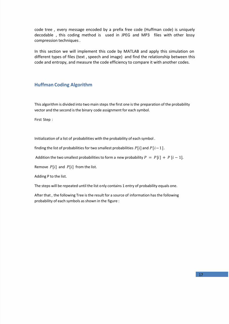
The Figure below shows such a matrix, constructed for the input string “mohammad ,murad ”.Each row is one of the fourteen rotations of the input, and the rows have been sorted lexically.The first column (F) of this matrix contains the first characters of the contexts, and the lastcolumn (L) contains the permuted characters that form the output of the BWT. The indexI inthis example is 10 as shown in the next figure.
7/24/2019 Implementation of a Digital Communucation System A
http://slidepdf.com/reader/full/implementation-of-a-digital-communucation-system-a 25/98
25
a bOutput L : dmrhaaomad,mum
After that the output text is suitable to be encoded usingMove-To-Front algorithm and then RLEand the entropy encoding as a final stage.Figure 7 shows the standard BWT steps , RLE is not Essential, and it is not included in thisimplementation.
Move-To-Front Transform
Move-to-Front encoding, is a scheme, as the name suggest, that uses a list of possiblesymbols and modifies it at every cycle (moving one symbol, the last one used). It usesthe fact, that in many cases, the appearance of data words are clustered in shortintervals. It uses self-organizing sequential search and variable-length encoding ofintegers. The advantages are that allows fast encoding and decoding, and requires only
mohammad,muradohammad,muradm
hammad,muradmoammad,muradmohmmad,muradmohamad,muradmohamad,muradmohammd,muradmohamma,muradmohammadmuradmohammad,uradmohammad,mradmohammad,muadmohammad,mur
dmohammad,mura
,muradmohammadad,muradmohamm
admohammad,murammad,muradmohd,muradmohammadmohammad,murahammad,muradmomad,muradmohammmad,muradmohamohammad,muradmuradmohammad,ohammad,muradmradmohammad,mu
uradmohammad,m
BWT MTF RLE Entropy
Coding
Figure 7 Typical scheme for the Burrows-Wheeler compression algorithm
Figure 6 BWT of the input text mohammad,murad N=14 ,I=10 (a) not sorted cycles (b) lexical ordered rows

7/24/2019 Implementation of a Digital Communucation System A
http://slidepdf.com/reader/full/implementation-of-a-digital-communucation-system-a 26/98
26
one pass over the data to be compressed. It is used here as a part of BWT that is beingdiscussed.
Word Position in dictionary Dynamic dictionary
of English alphabetbananaaa 1 (abcdefghijklmnopqrstuvwxyz)bananaaa 1,1 (bacdefghijklmnopqrstuvwxyz)bananaaa 1,1,13 (abcdefghijklmnopqrstuvwxyz)bananaaa 1,1,13,1 (nabcdefghijklmopqrstuvwxyz)bananaaa 1,1,13,1,1 (anbcdefghijklmopqrstuvwxyz)bananaaa 1,1,13,1,1,1 (nabcdefghijklmopqrstuvwxyz)bananaaa 1,1,13,1,1,1,0 (anbcdefghijklmopqrstuvwxyz)bananaaa 1,1,13,1,1,1,0,0 (anbcdefghijklmopqrstuvwxyz)Final code 1,1,13,1,1,1,0,0 (anbcdefghijklmopqrstuvwxyz)
For the word mohammad,murad its MTF transformation is 4,5,5,4,3,0,1,5,5,3,7,7,5,5 for adictionary ofits symbols. Or the dictionary can be used as all printable ASCII characters [ fromdecimal 32 to 126] , so no need to include it within compressed file .
Now , the BWT algorithm is implemented and applied to five text files , the results is comparedwith the Huffman coded files.
Text Files using BWT & Huffman Compression
BWT
# size beforebytes(.txt)
size afterbytes
Entropy of thesource text
Compressionfactor
1 1004 284 4.02 3.532 1.14k 474 4.18 2.43 2.29k 999 5.07 2.344 2.76k 0.989k 4.73 2.85 3.57k 1.33k 5.25 2.68
Huffman
# size beforebytes(.txt)
size afterbytes
Entropy of thesource text
Compressionfactor
1 1004 401 4.02 2.52 1.14k 513 4.18 2.273 2.29k 1.18k 5.07 1.944 2.76k 1.33k 4.73 2.075 3.57k 1.92k 5.25 1.85
Figure 8 MTF example for a word of repeated characters , bananaaa shown in steps

7/24/2019 Implementation of a Digital Communucation System A
http://slidepdf.com/reader/full/implementation-of-a-digital-communucation-system-a 27/98
27
It appears that BWT hasa greater compression factors than that Huffman has, this can beexplained due to the two transformations for the input text files BWT and MTF which changesthe permutation (rearrangement) and shape of the source symbols, consequently these twotransformation results in reduction of the source entropy before the last stage entropy codingas it shown in the table below
Source files has average4.63 bits per symbol while it is after BWT and MTF3.706 bits persymbol in average , this causes the increase of CR’s for these files by this technique. Now in thissample of text files BWT &MTF transform results in reducing files entropy in average withrespect to original by19.95%. The following figure shows the difference between Huffman and BWT compression for thetested text files :
In the last chapter more analysis is carried out with practical results and simulations.
File No. Entropy of the source textFile input
Entropy of the source afterBW&MTF transforms
1 4.02 3.4122 4.18 3.8813 5.07 4.154 4.73 3.4775 5.25 3.614
0.5 1 1.5 2 2.5 3 3.5 4 4.50.2
0.4
0.6
0.8
1
1.2
1.4
1.6
1.8
2
Size Before K B
S i z e
A f t e r
K B
BWT
HUFFMAN
Figure 9 Comparison between BWT and Huffman coding for text files shows the size before against size after in K Bytes

7/24/2019 Implementation of a Digital Communucation System A
http://slidepdf.com/reader/full/implementation-of-a-digital-communucation-system-a 28/98
28
The Decoding of Burrows-Wheeler Transform
The Burrows-Wheeler Transform has two methods of decoding, the first one is depending onthe adding and sorting of the output text to have a matrix M of N x N size in such a way toreverse the coding process this method is easy and straight forward but it need more computertime to be done, the original stringS is not obtained directly .
The second method is depending on the permutations it is more difficult than the first but itneeds less commuting time and storage and it will be described.
This method ,unlike the first one , its output is the original stringS , at the beginning, we havethe transformed string Land the index I.
L : d m r h a a o m a d , m u m
In the first step, the stringL is sorted lexicographically and calledF :
F : , a a a d d h m m m m o r u
It is similar to the first row ofM’ matrix .
Define the correspondence vector T of the length N, whose elements are numbers between1 and N. The correspondence is defined as given that each k is uniqueinteger and cannot be appear more than once starting from the first appearance .
in this example the correspondence vectorT is like this :
T = (5 ,8 ,13 ,7 ,2 ,3 ,12 ,9 , 4 ,6 ,1 ,10 ,14 ,11 )
T(1)=5 states that L(1) has the index 5 at vectorF , or in other words “d” in the fifth positionin F.
It is given thatin general L(I) is the last character ofS , in this exampleI=10 , L(10)=”d”which is the last character ofS =mohammad,murad
Now the text could be reconstructed fromL and T with the following relations and steps“it will
be appear that each step depends on the previous step while the first one depends on the
index I ” : Starting from the last symbol ofS
N: the number of elements of S

7/24/2019 Implementation of a Digital Communucation System A
http://slidepdf.com/reader/full/implementation-of-a-digital-communucation-system-a 29/98
29
From i = 1 ... to N-1 And
To illustrate that, the previous example is taken;
First step
From i = 1 to 14 ;
N=14i=1
S( N 1 ) = S( 13 ) = L ( X 1 )
X i = T i ( X i 1 )
X 1 = T 1 ( X 0 ) = T 1 ( 10 ) = 6
So ,
S( 13 ) = L ( 6
i=2
S( N 2 ) = S( 12 ) = L ( X 2 )
X 2 = T 2 ( X 1 ) = T 2 ( 6 ) = 3
S( 12 ) = L ( 3
i=3
S( N 3 ) = S( 11 ) = L ( X 3 )X 3 = T 3 ( X 2 ) = T 3 ( 3 ) = 13S( 11 ) = L ( 13 u

7/24/2019 Implementation of a Digital Communucation System A
http://slidepdf.com/reader/full/implementation-of-a-digital-communucation-system-a 30/98
30
………………………………………… (1)
………………………………………… (2)
………………………………………… (3)
………………………………………… (4)
i=4
S( N 4 ) = S( 10 ) = L ( T 4 (13 ) ) = L ( 14 ..
And continue...
i=13
S( N 13 ) = S( 1 ) = L ( X 13 )X 14 = T 14 ( X 12 ) = T 14 ( 5 ) = 2
S( 11 ) = L ( 2
Then allS elements are obtained .
To summarize the relations that are used to decoding so far :
Where: , : r epresents index of T in the process of decoding

7/24/2019 Implementation of a Digital Communucation System A
http://slidepdf.com/reader/full/implementation-of-a-digital-communucation-system-a 31/98

7/24/2019 Implementation of a Digital Communucation System A
http://slidepdf.com/reader/full/implementation-of-a-digital-communucation-system-a 32/98
32
Chapter Two
CHANNELCODING Implementation of Binary BCH Linear Block
Codes Encoder & DecoderThis chapter is a study and implementation of a BCH channel codes with important concepts suchas the Joint Entropy and Conditional Entropy and its relationship with channel capacity and thecapacity of two channel models BSC and AWGN channel.
7/24/2019 Implementation of a Digital Communucation System A
http://slidepdf.com/reader/full/implementation-of-a-digital-communucation-system-a 33/98
33
Channel Coding Overview
Channel coding or error control coding is a part of a Digital communication system used todetect the errors in the transmitted data and correct it using redundant bits added to theoriginal data according to a specific algorithm
This technique is divided into two parts the first is the forward error correction code FEC thatused to detect the errors and correcting without the need of retransmission that is in theconditions of good BER and the second is Automatic repeat request ARQ which is used underhuge errors to request a retransmission of data .
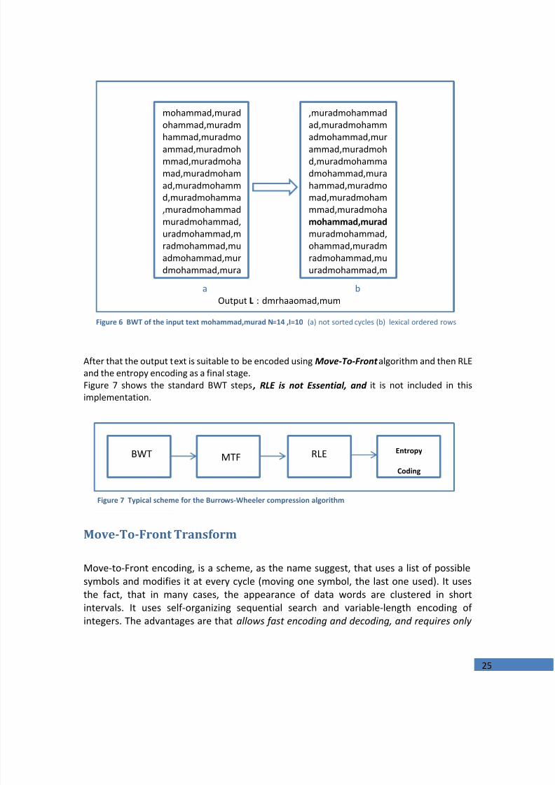
This figure shows the channel coding main parts :
Hamming Distance and Codeweight
- Two main measures for the coding performance are the hamming distance and codeweight which are defined as: Hamming distance is number of places, bits in which theydiffer in two different codes but code weight is the number of one’s in the code .
The forward error correction coding is divided into main coding types which are the Block Codes ,convolutional codes and Turbo Codes
Block Codes
The block codes is a channel coding technique that is divide the data which being transmittedinto a fixed length blocks called CodewordsC each of these Codewords is being coded accordingto an algorithm, if the output is containing the original data with parity bits the block code iscalled systematic but if the output is a new code without containing the original input datacodeword explicitly then it is calledunsystematic .
Figure 0.1 Channel Coding Classifications

7/24/2019 Implementation of a Digital Communucation System A
http://slidepdf.com/reader/full/implementation-of-a-digital-communucation-system-a 34/98
34
For the block codes –which is the chapter topic, The error correction performance of a blockcode is described by the minimum Hamming distance between each pair of code words, and iscalled the distance of the code.
The binary information sequence at the encoder input has a rate of . Mainly there are
two types of channel encoding techniques. The first is the block coding, by which a blocks of information bits are encoded into corresponding bits blocks. Each bits is called a code wordwith a total number of possible code words. The code rate, defined as the ratio , is ameasure of the amount of the redundancy introduced by the specific block coding technique.
A block code C is constructed by breaking up the message data stream into blocks of lengthhas the form , and mapping these blocks into code words in C . Theresulting code consists of a set of M code words . Each code word has afixed length denoted by and has a form
The elements of the code word are selected from an alphabet field of q elements. In thebinarycode case , which is our implementation, the field consists of two elements, 0 and 1. On theother hand, when the elements of the code word are selected from a field that has q alphabetelements, the code is non-binary code . As a special case when q is a power of 2 (i.e. )where is a positive integer, each element in the field can be represented as a set of distinct bits. As indicated above, codes are constructed from fields with a finite number of q elementscalledGalois field and denoted by
In general, finite field can be constructed if q is a prime or a power of prime number.When q is a prime, the consist of the elements with addition andmultiplication operations are defined as a modulo- q . If q is a power of prime (i.e.
where m is any positive integer), it is possible to extend the field to the field . This is called the extension field of and in this casemultiplication and addition operations are based on modulo- p arithmetic.
To construct the elements of the extension from the binary withelements 0 and 1, a new symbol α is defined with multiplication operation properties as: and . The elements of the that satisfy the above properties are . As the field shouldhas elements and be closed under multiplication α should satisfies the condition . Hence; the elements of the extension
are
which is a
commutative group under an addition and Multiplication (excluding the zero element)operations. is called a primitive element since it can generate all other field elements and it isa root of a primitive polynomial . So each element in the field can be represented as a setof m-tuple bits. To make the picture clear, Table at page 42 shows the three representationfor the elements of with a primitive polynomial as our study caseand implementation.

7/24/2019 Implementation of a Digital Communucation System A
http://slidepdf.com/reader/full/implementation-of-a-digital-communucation-system-a 35/98
35
Channel Capacity
Entropy , Information and Capacity
According to the information theory and mathematical models for representing it, from theprevious chapter, the entropy is defined as average information that is associated with thesource of information, mathematically it represented by
∑
Now suppose the X is a binary source of information with zero probability isP the entropy isdiscussed in the previous chapter and it is
For discrete binary random variable the entropy could be denoted as H(P)
The Joint Entropy and Conditional Entropy
If the two variables X and Yare jointly distributed as P(X,Y) then the joint entropy is denoted asH(X,Y) and has mathematical equation
∑∑
If one of these variables has the probability given another variable P(Y|X) then the conditionalentropy is
∑∑
∑∑
Form the last equation the joint entropy could be rewritten according to a chain rule as
This means that the entropy of X and Y is the entropy of X plus what Y has (entropy oruncertainty) given the knowing of X.
As for entropy the information is defined for a source X as

7/24/2019 Implementation of a Digital Communucation System A
http://slidepdf.com/reader/full/implementation-of-a-digital-communucation-system-a 36/98
36
∑
The mutual information is defined in previous chapter as
∑
The channel capacity
The channel is defined as a probabilistic device that is fully described by the conditionalprobability functionP(Y|X) and represented as
Now, the channel capacity “ C ” is defined as the maximum average information that can betransmitted over the channel per each channel use, mathematically :
If the chancel carries binary data as input and output with probability of receive one orzero is P and the other is 1-P if the rows of the channel transition matrix that containsp(y|x) permutations of each other, and the columns are permutations of each otherthen the channel is a binary symmetric channel BSC this channel also as discretememory less DMC . The previous channel characteristics could be represented as
P (y | x) x y
Figure 0.2 Mathematical Model Of The Channel
0
1
0
11 - p
1 - p
Figure 0.3 BSC with inputs, outputs and receptionprobabilities
7/24/2019 Implementation of a Digital Communucation System A
http://slidepdf.com/reader/full/implementation-of-a-digital-communucation-system-a 37/98
37
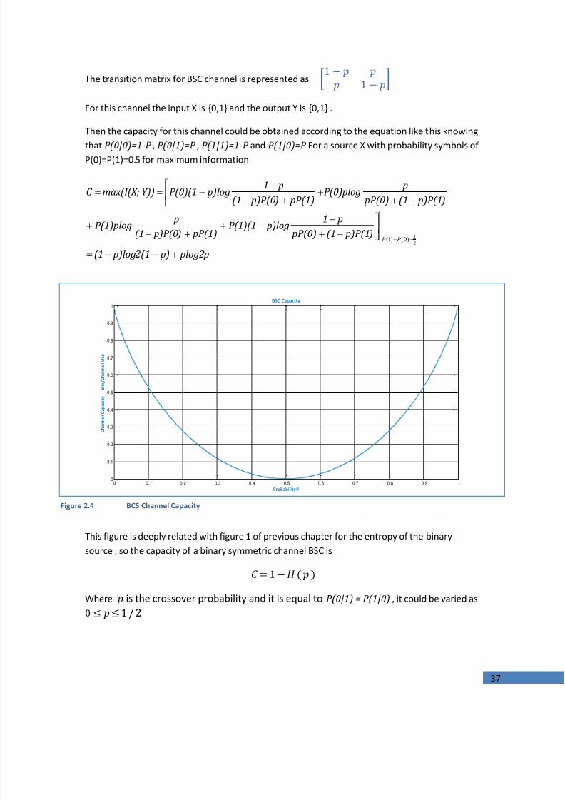
The transition matrix for BSC channel is represented as
For this channel the input X is {0,1} and the output Y is {0,1} .
Then the capacity for this channel could be obtained according to the equation like this knowingthat P(0|0)=1-P , P(0|1)=P , P(1|1)=1-P and P(1|0)=P For a source X with probability symbols ofP(0)=P(1)=0.5 for maximum information
plog2p p) p)log2(1(1
p)P(1)(1 pP(0) p1
p)logP(1)(1 pP(1) p)P(0)(1
pP(1)plog
p)P(1)(1 pP(0) p
P(0)plog pP(1) p)P(0)(1
p1 p)logP(0)(1Y))max(I(X;C
2
1)0()1( P P
This figure is deeply related with figure 1 of previous chapter for the entropy of the binarysource , so the capacity of a binary symmetric channel BSC is
Where is the crossover probability and it is equal toP(0|1) = P(1|0) , it could be varied as
0 0.1 0.2 0.3 0.4 0.5 0.6 0.7 0.8 0.9 10
0.1
0.2
0.3
0.4
0.5
0.6
0.7
0.8
0.9
1
Probability P
C h a n n e l C a p a c i t y
B i t s
/ C h a n n e l U s e
BSC Capacity
Figure 2.4 BCS Channel Capacity

7/24/2019 Implementation of a Digital Communucation System A
http://slidepdf.com/reader/full/implementation-of-a-digital-communucation-system-a 38/98
38
Capacity for Additive White Gaussian Noise Channel
This channel model is more important since most of the channel coding techniques are designedand tested according to this model , the AWGN channel has a noise power densityN 0 that is
normally distributed according to Gaussian distribution function , it is characterized as
√
The capacity for continuous-time input and output signals of this channel is given by
Where H(Y) the entropy of the continues time output signal and it is defined as :
∫
And H(N) the entropy of the Gaussian Noise
Now if the signal is band limited with a bandwidthB then the capacity according to Shannon-Hartley theorem is
)
Where S is the power of input signal to the channel and N = N 0 B is the noise power
Finally the capacity of an AWGN channel is deeply related to the input signal to the channelsignal to noise ratio and the allocated bandwidth and it is dependent on the digital modulationscheme .
Finally the AWGN channel is chosen since this chapter will be an analysis implementation of asource coding techniques that aims at adding redundant bits to its input codeword to enable theerror detection and correction and to reduce the probability of error over AWGN channel.
7/24/2019 Implementation of a Digital Communucation System A
http://slidepdf.com/reader/full/implementation-of-a-digital-communucation-system-a 39/98
39
Block Channel Coding
BCH codes:
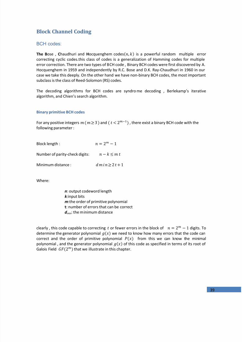
The Bose , Chaudhuri and Hocquenghem codes is a powerful random multiple error
correcting cyclic codes.this class of codes is a generalization of Hamming codes for multipleerror correction. There are two types of BCH code , Binary BCH codes were first discovered by A.Hocquenghem in 1959 and independently by R.C. Bose and D.K. Ray-Chaudhuri in 1960 in ourcase we take this deeply. On the other hand we have non-binary BCH codes, the most importantsubclass is the class of Reed-Solomon (RS) codes.
The decoding algorithms for BCH codes are syndrome decoding , Berlekamp’s iterativealgorithm, and Chien’s search algorithm.
Binary primitive BCH codes
For any positive integers and , there exist a binary BCH code with thefollowing parameter :
Block length :
Number of parity-check digits:
Minimum distance :
Where:
n : output codeword lengthk :input bitsm :the order of primitive polynomialt : number of errors that can be correctd min: the minimum distance
clearly , this code capable to correcting or fewer errors in the block of digits. Todetermine the generator polynomial we need to know how many errors that the code can
correct and the order of primitive polynomial from this we can know the minimalpolynomial , and the generator polynomial of this code as specified in terms of its root ofGalois Field that we illustrate in this chapter.

7/24/2019 Implementation of a Digital Communucation System A
http://slidepdf.com/reader/full/implementation-of-a-digital-communucation-system-a 40/98
40
Mathematical Related Concepts
Minimal polynomials:
Let α be an element in. We call the monic polynomial of smallest degree which hascoefficients in and α and its conjugates as a root, the minimal polynomial of α.or in
other word The minimal polynomial isirreducible over , and any other non-zeropolynomial GF with is a (polynomial) multiple of .
All the field elements of the form () and is odd, are calledconjugates of andall of them over the defined field have the same minimal polynomial (i.e.
)Hence, every even power of in has the same minimal polynomial as the preceding oddpower of .
The primitive polynomial is used to obtain the generator polynomial ,and is the order of
the primitive polynomial we will talk about this in the next part.There is a lot of theorems for the minimal polynomial but the most important theoremsare chosen to be considered:
The first theorem which describes the first minimal polynomial over the finite filed states that :
If be the minimal polynomial of an element a in and is irreducible.
And by the definition the minimal polynomial
That is needed to determine the next minimal polynomial.
The second theorem describes how to construct the minimal polynomial and states that:
If be a polynomial over , and α is a root of of order in the multiplicativegroup of some field F of characteristic p. and Let r be the smallest integer so that pr+1 1 mod n.then α, α p, αp^2, ..., αp^r are all distinct roots of P(x).
To find the minimal polynomial :
( ) Where :p: the order of that is needed to find the minimal polynomialr: integer numberTo illustrate the previous mathematical theory we consider the field this means theorder of is 4 and the primitive polynomial may be , and we need todetermine what will be

7/24/2019 Implementation of a Digital Communucation System A
http://slidepdf.com/reader/full/implementation-of-a-digital-communucation-system-a 41/98

7/24/2019 Implementation of a Digital Communucation System A
http://slidepdf.com/reader/full/implementation-of-a-digital-communucation-system-a 42/98
42
Encoding of BCH code
After the preparation of the generator polynomial we go with steps to encode the data.
Step 1:
Generator matrix is the most important and the complex step to encode the data that will besend and the dimensions of the matrix is .
Generator matrix can be construct by put the coffecient of the generator polynomial andfollowed by zeros with length of the parity bits and in the next row we shift one columnand so on , and after this we need to make from column number 1 to as identity because wedeal with systematic code . And we obtain the most general generator matrix as
Where:
I k : is the identity matrix of dimensions P :parity matrix of dimensions
Step 2 :
After we get the generator matrix actually we need to obtain the codeword as equationbelow
Where:D: the information.G: the generation matrix
Now the codeword is formed and data is ready for transmission.
Step 3:
The check matrix for a systematic code can be found directly from the generator matrix.
7/24/2019 Implementation of a Digital Communucation System A
http://slidepdf.com/reader/full/implementation-of-a-digital-communucation-system-a 43/98
43
BCH(15,5,7) Study Case & implementation
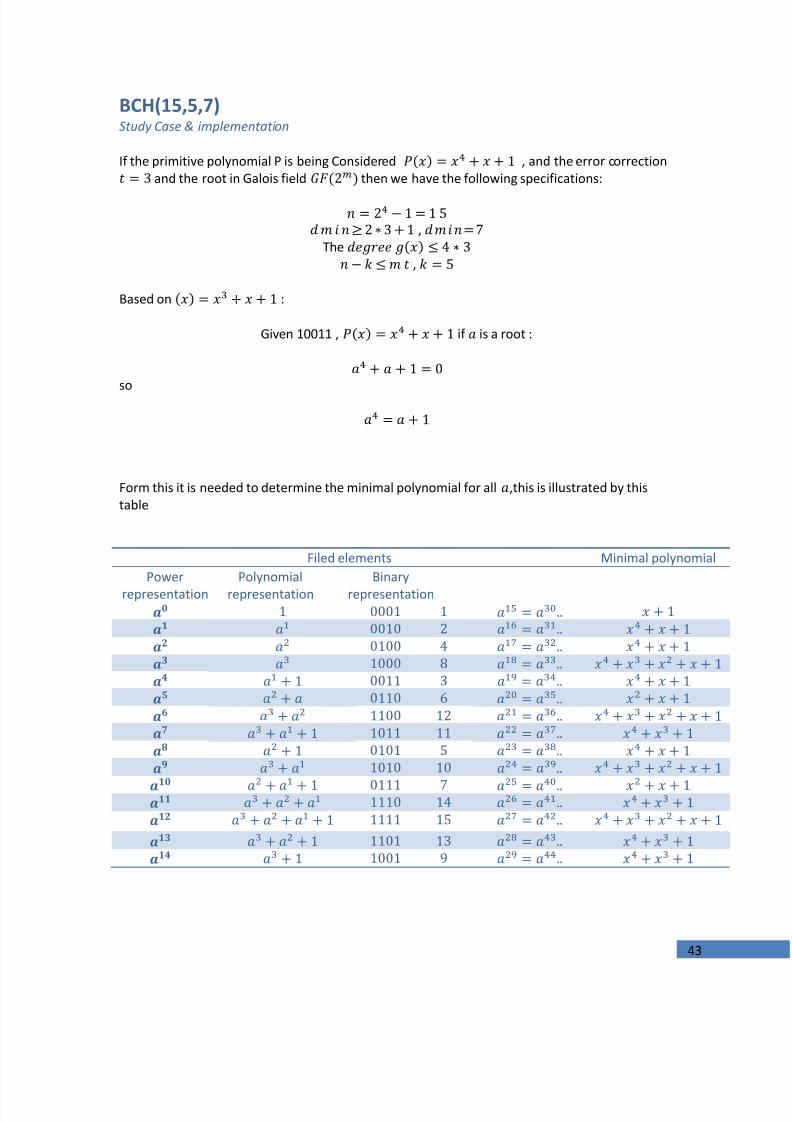
If the primitive polynomial P is being Considered , and the error correction and the root in Galois field then we have the following specifications:
,
The ,
Based on :
Given 10011 , if is a root :
so
Form this it is needed to determine the minimal polynomial for all,this is illustrated by thistable
Filed elements Minimal polynomialPower
representationPolynomial
representationBinary
representation

7/24/2019 Implementation of a Digital Communucation System A
http://slidepdf.com/reader/full/implementation-of-a-digital-communucation-system-a 44/98
44
To obtain the it could be written as
After the multiplication
So*;
And by the same way all minimal polynomials could be found.
Now the is the multiply of since
Therefor;
The coefficients of the is
]
* If we have then it is equal to zero , for each it could be replaced from the table above for example and , And since, we add without carry

7/24/2019 Implementation of a Digital Communucation System A
http://slidepdf.com/reader/full/implementation-of-a-digital-communucation-system-a 45/98
45
The generation matrix of k by n that is needed can be built by putting the generator poly in thefirst row and followed by zeros and in the next row is the one bit rotation of previous row
Now , first k columns of G must be identity matrixI k this matrix is thereduced row echelon form of the previous matrix and it has the form
Now The predefined parity check matrix is :
[
]
All possible codewords can be obtained by multiplying a Data of length bit by generatormatrix

7/24/2019 Implementation of a Digital Communucation System A
http://slidepdf.com/reader/full/implementation-of-a-digital-communucation-system-a 46/98
46
Decoding of BCH Codes
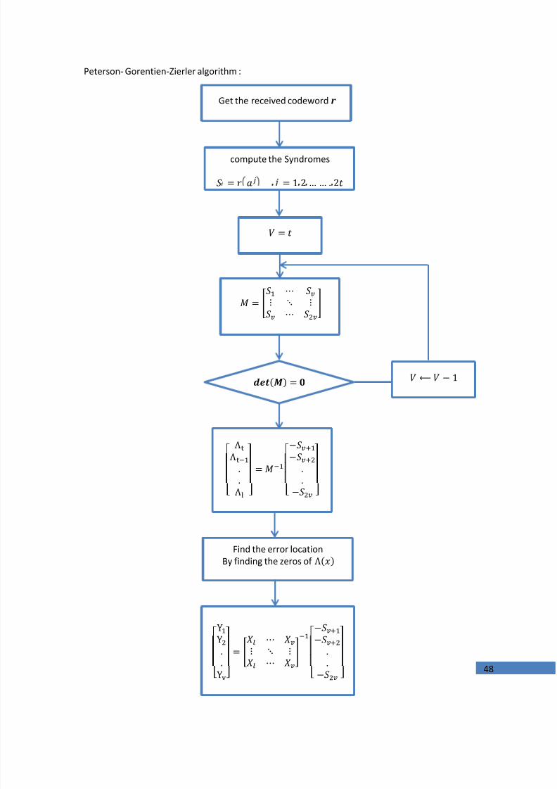
Decoding process of the BCH codes is the most challenging task. Mainly, we have three decodingalgorithms for BCH codes: Peterson- Gorentien-Zierler algorithm and Berlekamp- Masseyalgorithm, and syndrome, Peterson- Gorentien-Zierler algorithm is described here and also thesyndrome algorithm that is implemented .
Now , assume that the received code word is differs from the sent codeWord in positions , then the error code word willhave a nonzero elements at these positions and the error polynomial can be written as
Where
V: the maximum error allowed or v=t
For this algorithm its necessary to compute the syndromes of the received code wordpolynomial . define the syndrome to be
()
Or
.
.
Where
is the error locations. Defining what is called error locator polynomial as
So ,
7/24/2019 Implementation of a Digital Communucation System A
http://slidepdf.com/reader/full/implementation-of-a-digital-communucation-system-a 47/98
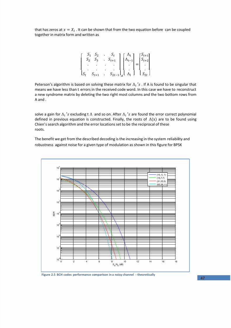
7/24/2019 Implementation of a Digital Communucation System A
http://slidepdf.com/reader/full/implementation-of-a-digital-communucation-system-a 48/98
48
Peterson- Gorentien-Zierler algorithm :
Get the received codewordr
compute the Syndromes
[Λ
Λ
Λ ]
[ ]
Find the error locationBy finding the zeros ofΛ
[
YY
Y]
[ ]
7/24/2019 Implementation of a Digital Communucation System A
http://slidepdf.com/reader/full/implementation-of-a-digital-communucation-system-a 49/98
49
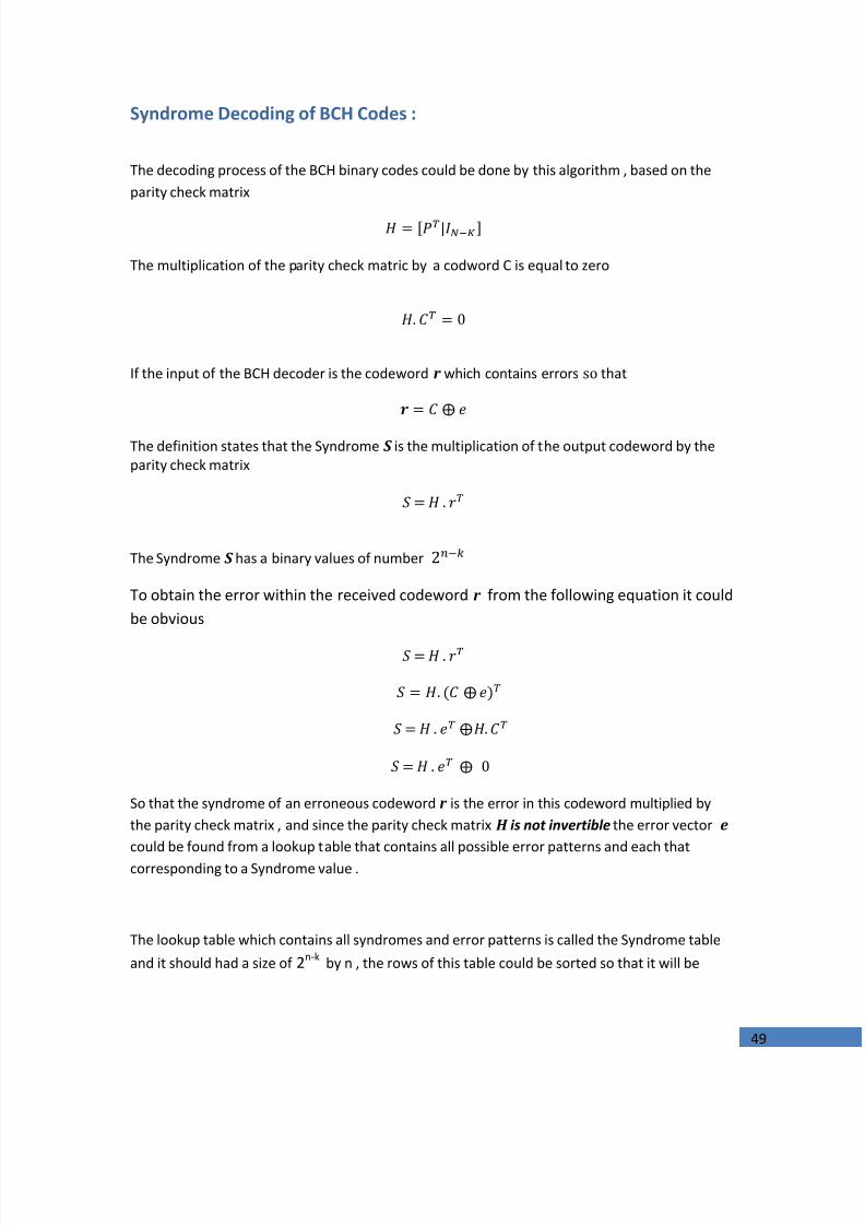
Syndrome Decoding of BCH Codes :
The decoding process of the BCH binary codes could be done by this algorithm , based on theparity check matrix
The multiplication of the parity check matric by a codword C is equal to zero
If the input of the BCH decoder is the codewordr which contains errors so that
The definition states that the Syndrome S is the multiplication of the output codeword by theparity check matrix
The Syndrome S has a binary values of number To obtain the error within the received codewordr from the following equation it couldbe obvious
So that the syndrome of an erroneous codewordr is the error in this codeword multiplied bythe parity check matrix , and since the parity check matrixH is not invertible the error vector e could be found from a lookup table that contains all possible error patterns and each thatcorresponding to a Syndrome value .
The lookup table which contains all syndromes and error patterns is called the Syndrome tableand it should had a size of2n-k by n , the rows of this table could be sorted so that it will be
7/24/2019 Implementation of a Digital Communucation System A
http://slidepdf.com/reader/full/implementation-of-a-digital-communucation-system-a 50/98
50
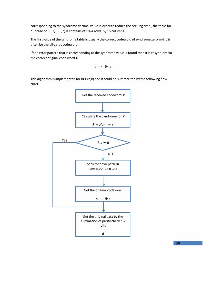
corresponding to the syndrome decimal value in order to reduce the seeking time , the table forour case of BCH(15,5,7) is contains of 1024 rows by 15 columns .
The first value of the syndrome table is usually the correct codeword of syndrome zero and it isoften be the all-zeros codeword
If the error pattern that is corresponding to the syndrome value is found then it is easy to obtainthe correct original code wordC.
This algorithm is implemented for BCH(n,k) and it could be summarized by the following flowchart
Get the received codeword r
Calculate the Syndrome forr
If
Seek for error patterncorresponding to s
Get the original codeword
Get the original data by theelimination of parity check n-k
bits
NO
YES

7/24/2019 Implementation of a Digital Communucation System A
http://slidepdf.com/reader/full/implementation-of-a-digital-communucation-system-a 51/98
51
Chapter Three
ENCRYPTION Data Security ImplementationThis chapter is a description and implementation of an Advanced Encryption Standard Rijndael
algorithm which is a symmetric encryption algorithm , another layer of security is added byimplementing a steganography system

7/24/2019 Implementation of a Digital Communucation System A
http://slidepdf.com/reader/full/implementation-of-a-digital-communucation-system-a 52/98
52
Encryption
Overview
Data that can be read and understood without any special measures is called plaintext or cleartext. The method of disguising plaintext in such a way as to hide its substance is calledencryption or in other words Encryption is the process of transforming information (referred toas plaintext) using an algorithm (called cipher) to make it unreadable to anyone except thosepossessing special knowledge, usually referred to as a key.
Symmetric encryption uses a single key to encrypt and decrypt the message. This means theperson encrypting the message must give that key to the recipient before they can decrypt it.
Asymmetric encryption , also known as Public-Key encryption, uses two different keys - a publickey to encrypt the message, and a private key to decrypt it. The public key can only be used toencrypt the message and the private key can only be used to decrypt it.
In this chapter the symmetric encryption is conceded to be analyzed, described andimplemented .The Advanced Encryption Standard is adopted in this chapter and it isrepresented by the a Rijndael algorithm with 128-bit cipher key.
Symmetric Encryption Processes
7/24/2019 Implementation of a Digital Communucation System A
http://slidepdf.com/reader/full/implementation-of-a-digital-communucation-system-a 53/98
53
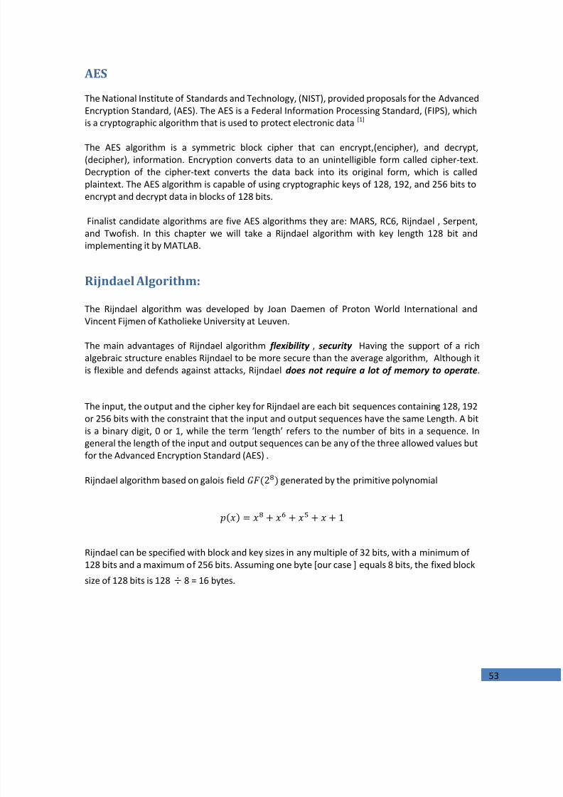
AES
The National Institute of Standards and Technology, (NIST), provided proposals for the AdvancedEncryption Standard, (AES). The AES is a Federal Information Processing Standard, (FIPS), whichis a cryptographic algorithm that is used to protect electronic data[1]
The AES algorithm is a symmetric block cipher that can encrypt,(encipher), and decrypt,(decipher), information. Encryption converts data to an unintelligible form called cipher-text.Decryption of the cipher-text converts the data back into its original form, which is calledplaintext. The AES algorithm is capable of using cryptographic keys of 128, 192, and 256 bits toencrypt and decrypt data in blocks of 128 bits.
Finalist candidate algorithms are five AES algorithms they are: MARS, RC6, Rijndael , Serpent,and Twofish. In this chapter we will take a Rijndael algorithm with key length 128 bit andimplementing it by MATLAB.
Rijndael Algorithm:
The Rijndael algorithm was developed by Joan Daemen of Proton World International andVincent Fijmen of Katholieke University at Leuven.
The main advantages of Rijndael algorithm flexibility , security Having the support of a richalgebraic structure enables Rijndael to be more secure than the average algorithm, Although itis flexible and defends against attacks, Rijndaeldoes not require a lot of memory to operate .
The input, the output and the cipher key for Rijndael are each bit sequences containing 128, 192
or 256 bits with the constraint that the input and output sequences have the same Length. A bitis a binary digit, 0 or 1, while the term ‘length’ refers to the number of bits in a sequence. Ingeneral the length of the input and output sequences can be any of the three allowed values butfor the Advanced Encryption Standard (AES) .
Rijndael algorithm based on galois field generated by the primitive polynomial
Rijndael can be specified with block and key sizes in any multiple of 32 bits, with a minimum of128 bits and a maximum of 256 bits. Assuming one byte [our case ] equals 8 bits, the fixed blocksize of 128 bits is 128÷ 8 = 16 bytes.

7/24/2019 Implementation of a Digital Communucation System A
http://slidepdf.com/reader/full/implementation-of-a-digital-communucation-system-a 54/98
54
The Basic Algorithm
For simplicity we choose a 128 bits length of data, this algorithm have a two branchesencryption and key scheduleWe will illustrate these deeply.
Specification of Rijndael Algorithm :
1.State
A byte in Rijndael is a group of 8 bits and is the basic data unit for all cipher operations. Suchbytes are interpreted as finite field elements using polynomial representation, where a byte bwith bits represents the finite field element:
∑
All input , output and the cipher key are represented as a one dimensional array of bits foressentially programming the input is converted to two dimensional array of bytes and thisprocess called state. In our case 128 bits, the state array is 4*4 of bytes however also the cipherkey also need to convert it in the same style that is mean 4*4 array of bytes.If there are a sequence of data that want to convert into a state thatcan be done by
Wherer : rowc : column
7/24/2019 Implementation of a Digital Communucation System A
http://slidepdf.com/reader/full/implementation-of-a-digital-communucation-system-a 55/98
55
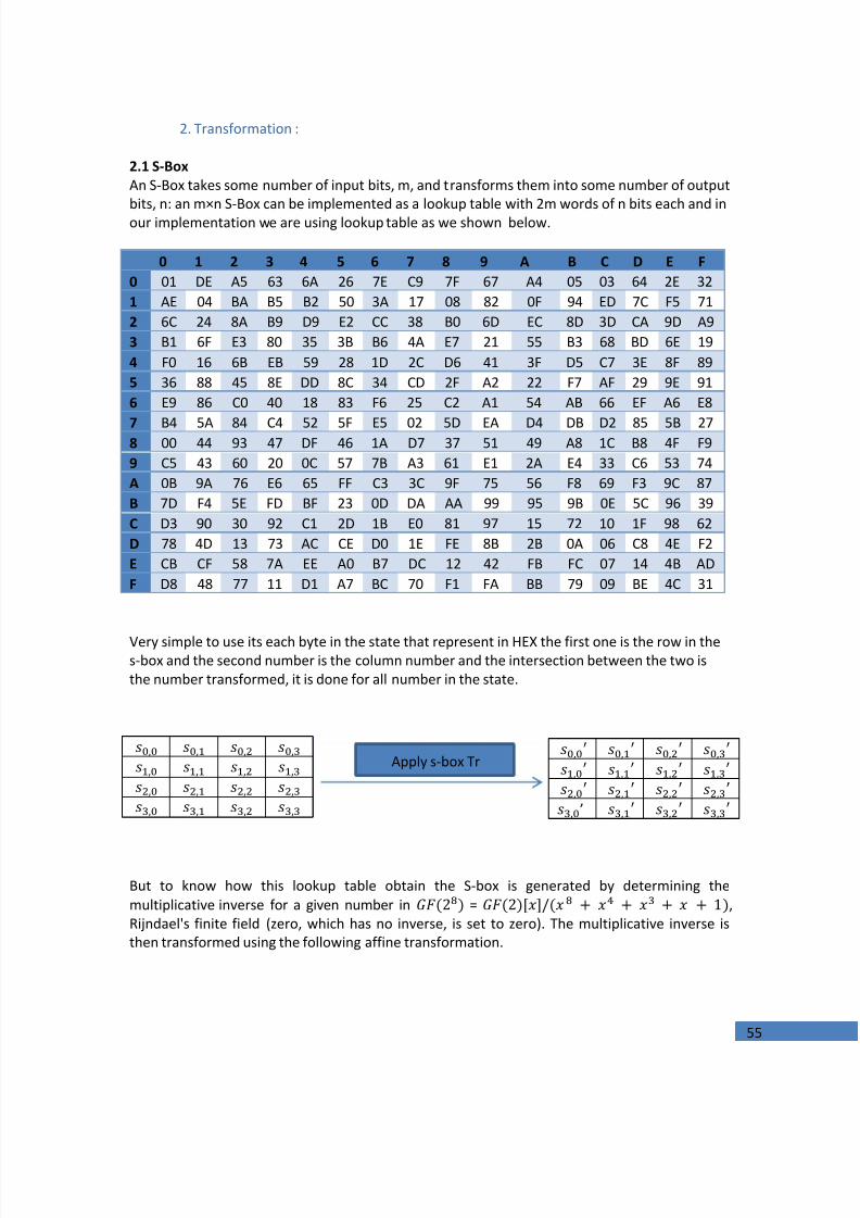
2. Transformation :
2.1 S-BoxAn S-Box takes some number of input bits, m, and transforms them into some number of outputbits, n: an m×n S-Box can be implemented as a lookup tablewith 2m words of n bits each and inour implementation we are using lookup table as we shown below.
0 1 2 3 4 5 6 7 8 9 A B C D E F0 01 DE A5 63 6A 26 7E C9 7F 67 A4 05 03 64 2E 321 AE 04 BA B5 B2 50 3A 17 08 82 0F 94 ED 7C F5 712 6C 24 8A B9 D9 E2 CC 38 B0 6D EC 8D 3D CA 9D A93 B1 6F E3 80 35 3B B6 4A E7 21 55 B3 68 BD 6E 194 F0 16 6B EB 59 28 1D 2C D6 41 3F D5 C7 3E 8F 895 36 88 45 8E DD 8C 34 CD 2F A2 22 F7 AF 29 9E 916 E9 86 C0 40 18 83 F6 25 C2 A1 54 AB 66 EF A6 E8
7 B4 5A 84 C4 52 5F E5 02 5D EA D4 DB D2 85 5B 278 00 44 93 47 DF 46 1A D7 37 51 49 A8 1C B8 4F F99 C5 43 60 20 0C 57 7B A3 61 E1 2A E4 33 C6 53 74A 0B 9A 76 E6 65 FF C3 3C 9F 75 56 F8 69 F3 9C 87B 7D F4 5E FD BF 23 0D DA AA 99 95 9B 0E 5C 96 39C D3 90 30 92 C1 2D 1B E0 81 97 15 72 10 1F 98 62D 78 4D 13 73 AC CE D0 1E FE 8B 2B 0A 06 C8 4E F2E CB CF 58 7A EE A0 B7 DC 12 42 FB FC 07 14 4B ADF D8 48 77 11 D1 A7 BC 70 F1 FA BB 79 09 BE 4C 31
Very simple to use its each byte in the state that represent in HEX the first one is the row in thes-box and the second number is the column number and the intersection between the two isthe number transformed, it is done for all number in the state.
But to know how this lookup table obtain the S-box is generated by determining themultiplicative inversefor a given number in = ,Rijndael's finite field(zero, which has no inverse, is set to zero). The multiplicative inverse isthen transformed using the following affine transformation.
’
Apply s-box Tr

7/24/2019 Implementation of a Digital Communucation System A
http://slidepdf.com/reader/full/implementation-of-a-digital-communucation-system-a 56/98
56
[
][][]
Where is the multiplicative inverse as a vector.
The matrix multiplication can be calculated by the following algorithm:
Store the multiplicative inverse of the input number in two 8-bit unsigned temporaryvariables: s and x.
Rotate the value s one bit to the left; if the value of s had a high bit (eighth bit from theright) of one, make the low bit of s one; otherwise the low bit of s is zero.
Exclusive or the value of x with the value of s, storing the value in x For three more iterations, repeat steps two and three; steps two and three are done atotal of four times.
The value of x will now have the result of the multiplication.
After the matrix multiplication is done, exclusive or the value by the decimal number 99 (thehexadecimal number 0x63, the binary number 1100011, and the bit string 11000110representing the number in LSb first notation).
Or we can put this matrix into an equation as follow
Where
And each bit of the byte that we need to transform.
2.2 Shift Rows
The Shift Rows transformation operates individually on each of the last three rows of the stateby cyclically shifting the bytes depends on the number of the rows, wedon’t have shift inrow(0) but row(1) we have a one cycle shift and so on.as illustrated below

7/24/2019 Implementation of a Digital Communucation System A
http://slidepdf.com/reader/full/implementation-of-a-digital-communucation-system-a 57/98
57
Where
is the state after transformed by s-box
2.3 Mix columns
The Mix Columns transformation acts independently on every column of the state take eachcolumn and multiply it by mix columns matrix as follow:
[ ]
This can also be seen as the following:
This can be done only by multiplication in the field . as we illustrated in channel coding chapter .
2.4 Add round key
In the add Round Key transformation, from the key schedule (the round key described later) areeach added (XOR’ d) into the columns of the state so that:
This is done four times in each round to apply this transform.
’
Apply shift rows Tr

7/24/2019 Implementation of a Digital Communucation System A
http://slidepdf.com/reader/full/implementation-of-a-digital-communucation-system-a 58/98
58
3.Key schedule
In this algorithm the length of cipher key is 128 bits, which is generated into 4 * 4 bytes. Labelthe first four columns as respectively . From this primary key we needto generate round keys for all 10 rounds with 128 bits .and we need in these steps S-box andRcon that is illustrated as follows:
Rcon (Round Column)
Is something that should be used when we generate a first column in each round
01 02 04 08 10 20 40 80 1b 390 0 0 0 0 0 0 0 0 00 0 0 0 0 0 0 0 0 00 0 0 0 0 0 0 0 0 0
We can get the first columns of all round keys by
Where: : the number of the column
:the round key at such column : the number of the round
This equation can be used at first column in each roundonly.
Now we need to generate all key rounds and we will illustrate it step by step :
Round (0):
It takes the primary key
Round (1):
The first column of this round key if we called , that takes the last column of the primary key and rotate it once then go to the S-box and replace all elements of this column or that can
be expressed as
And the remaining columns can be obtained by
From round 2 to round 10 keys which is the same idea in round 1 key

7/24/2019 Implementation of a Digital Communucation System A
http://slidepdf.com/reader/full/implementation-of-a-digital-communucation-system-a 59/98

7/24/2019 Implementation of a Digital Communucation System A
http://slidepdf.com/reader/full/implementation-of-a-digital-communucation-system-a 60/98
60
Decryption
To decrypt, perform cipher in reverse order, using inverses of the transformation and the samekey schedule.
Cipher text
Add round key
Inverse Shift rows
Inverse Sub bytes
Add round key
Inverse Mix columns
Add round key
Inverse Sub bytes
Inverse Shift rows
State
Round key (10)
Round key(R)
Cipher key
7/24/2019 Implementation of a Digital Communucation System A
http://slidepdf.com/reader/full/implementation-of-a-digital-communucation-system-a 61/98
61
Inverse transformation:
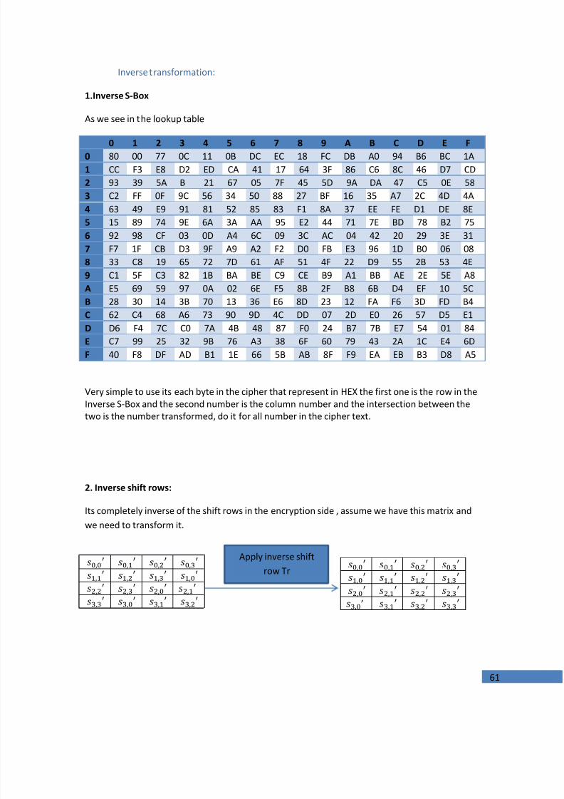
1.Inverse S-Box
As we see in the lookup table
0 1 2 3 4 5 6 7 8 9 A B C D E F0 80 00 77 0C 11 0B DC EC 18 FC DB A0 94 B6 BC 1A1 CC F3 E8 D2 ED CA 41 17 64 3F 86 C6 8C 46 D7 CD2 93 39 5A B 21 67 05 7F 45 5D 9A DA 47 C5 0E 583 C2 FF 0F 9C 56 34 50 88 27 BF 16 35 A7 2C 4D 4A4 63 49 E9 91 81 52 85 83 F1 8A 37 EE FE D1 DE 8E5 15 89 74 9E 6A 3A AA 95 E2 44 71 7E BD 78 B2 756 92 98 CF 03 0D A4 6C 09 3C AC 04 42 20 29 3E 317 F7 1F CB D3 9F A9 A2 F2 D0 FB E3 96 1D B0 06 088 33 C8 19 65 72 7D 61 AF 51 4F 22 D9 55 2B 53 4E
9 C1 5F C3 82 1B BA BE C9 CE B9 A1 BB AE 2E 5E A8A E5 69 59 97 0A 02 6E F5 8B 2F B8 6B D4 EF 10 5CB 28 30 14 3B 70 13 36 E6 8D 23 12 FA F6 3D FD B4C 62 C4 68 A6 73 90 9D 4C DD 07 2D E0 26 57 D5 E1D D6 F4 7C C0 7A 4B 48 87 F0 24 B7 7B E7 54 01 84E C7 99 25 32 9B 76 A3 38 6F 60 79 43 2A 1C E4 6DF 40 F8 DF AD B1 1E 66 5B AB 8F F9 EA EB B3 D8 A5
Very simple to use its each byte in the cipher that represent in HEX the first one is the row in theInverse S-Box and the second number is the column number and the intersection between the
two is the number transformed, do it for all number in the cipher text.
2. Inverse shift rows:
Its completely inverse of the shift rows in the encryption side , assume we have this matrix andwe need to transform it.
’
Apply inverse shiftrow Tr

7/24/2019 Implementation of a Digital Communucation System A
http://slidepdf.com/reader/full/implementation-of-a-digital-communucation-system-a 62/98
62
3. Inverse mix Columns
The inverse Mix Columns transformation acts independently on every column of the cipher takeeach column and multiply it by mix columns matrix as follow:
This can also be seen as the following:
This can be done only by multiplication in the field .
4.inverse Add round key
In the inverse add Round Key transformation, from the key schedule (the round key describedbefore) are each added (XOR’ d) into the columns of thecipher so that:
It is done four times in each round to apply this transform.After carrying out these transformation like decryption flow chart and using the same cipherkey that used in encryption we should recover the same file that encrypted.
Assume we have a text file which contains murad,mohammad
murad,mohammad 109 117 114 97 100 44 109 111 104 97 109 109 97 100
In this example we have 14 bytes only so we need to add two zeros as result we need 16 bytes.Cipher key : [43 40 171 9 126 174 247 207 21 210 21 79 22 166 136 60]
Then the cipher text is
And at the decryption side the recovered data is murad,mohammad
ASCII representation
7/24/2019 Implementation of a Digital Communucation System A
http://slidepdf.com/reader/full/implementation-of-a-digital-communucation-system-a 63/98
63
Steganography As a second data security layer
Steganography can be defined as the science of writing hidden messages in such a way that no
one, except the sender and intended recipient, can detect the existence of the message
Steganography has a difference with cryptography. While the Cryptography involves the
encryption algorithms that change the message symbols as it done with the AES . An encrypted
message is obvious. One may not know the intended meaning of the message, but it is obvious
that it exists!
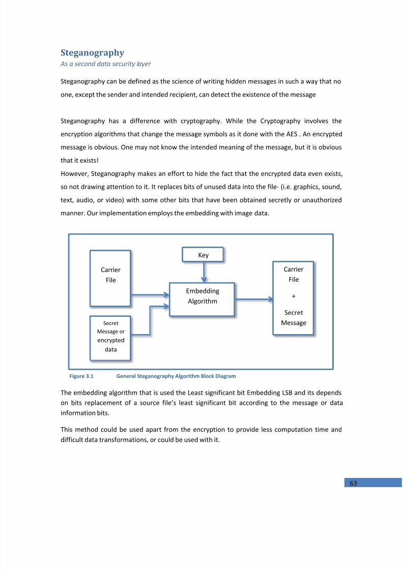
However, Steganography makes an effort to hide the fact that the encrypted data even exists,
so not drawing attention to it. It replaces bits of unused data into the file- (i.e. graphics, sound,
text, audio, or video) with some other bits that have been obtained secretly or unauthorizedmanner. Our implementation employs the embedding with image data.
The embedding algorithm that is used the Least significant bit Embedding LSB and its dependson bits replacement of a source file’s least significant bit according to the message or datainformation bits.
This method could be used apart from the encryption to provide less computation time anddifficult data transformations, or could be used with it.
CarrierFile
SecretMessage orencrypted
data
Embedding
Algorithm
CarrierFile
+Secret
Message
Key
Figure 3.1 General Steganography Algorithm Block Diagram

7/24/2019 Implementation of a Digital Communucation System A
http://slidepdf.com/reader/full/implementation-of-a-digital-communucation-system-a 64/98
64
Chapter Four
SYSTEMIMPLEMENTATIONMATLAB Implementation of the System
This chapter introduces the programming codes and MATLAB functions that are created so thatto carry out the operations and tasks that each block in the digital communication system performs.

7/24/2019 Implementation of a Digital Communucation System A
http://slidepdf.com/reader/full/implementation-of-a-digital-communucation-system-a 65/98
65
0 0.5 1 1.5 2 2.5 3 3.5 4 4.5 5 5.5 6 6.5 7 7.5 8 8.5 9 9.5 10 10.5 11 11.5 12 12.5 13 13.5 14 14.5 15 15.5 16 16.5 17 17.5 18 18.5 19 19.5 200
2
4
6
8
10
12
14
16
18
20
22
24
26
28
30
32
34
36
38
40
Size Before KB
S i z e
A f t e r
K B
BWTHuffman
RARRun-Length
System Performance Simulations
The Source CoderIn order to carry out this test, there is a set of different size and type files to be encoded, thecompressed or encoded files (the output) are then compared with the input files according tosome parameters. The coders that are used Huffman, Run-Length, and BWT.
The next figure shows the difference in the size after and before for the chosen text files
Filename
SizeBefore
[Bytes]
BWT
[Bytes]
Huffman
[Bytes]
RunLength
[Bytes]
RAR
[Bytes]
Average codeLength forHuffman
[Bits/symbol]
Average codeLength for
BWT[Bits/symbol]
EntropyOf the source
[Bits/symbol]File 1 1k 0.532k 0.664 k 1.53 k 0.47 4.40 2.94 4.38File 2 1.36 k 0.787k 0.874 k 2.67 k 0.77 4.40 3.59 4.38
File 3 3.66 k 1.96 k 2.40 k 7.16 k 1.88 4.89 3.74 4.85File 4 4.12k 1.95 k 2.62 k 7.72 k 1.82 4.75 3.27 4.72File 5 6.08 k 2.92 k 4.05 k 11.9 k 2.82 5.09 3.5 5.05File 6 12.7 k 5.02 k 7.21 k 25 k 4.87 4.41 2.97 4.39File 7 16.0 k 6.02 k 9.14 k 31.5 k 5.85 4.46 2.85 4.44File 8 18.1 k 6.75 k 10.2 k 35.6 k 6.72 4.45 2.85 4.43
Figure 4.1 comparison plot for the three encoders compared with RAR
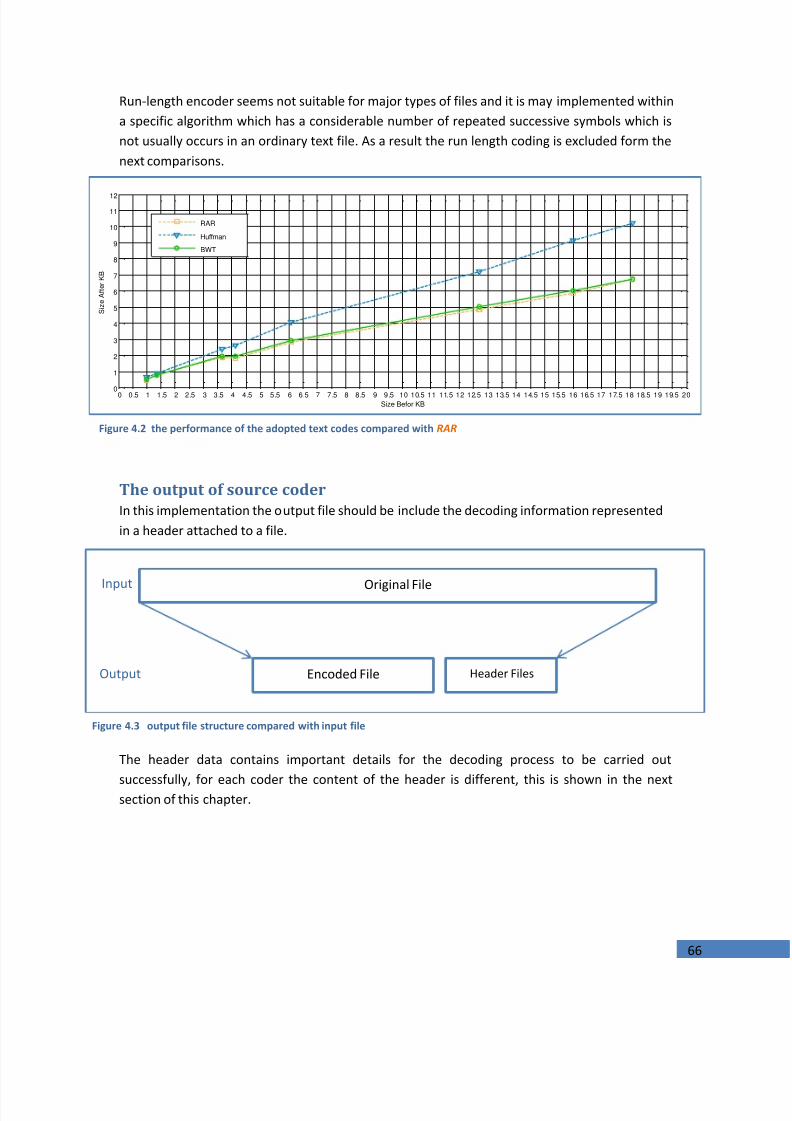
7/24/2019 Implementation of a Digital Communucation System A
http://slidepdf.com/reader/full/implementation-of-a-digital-communucation-system-a 66/98
66
0 0.5 1 1.5 2 2.5 3 3.5 4 4.5 5 5.5 6 6.5 7 7.5 8 8.5 9 9.5 10 10.5 11 11.5 12 12.5 13 13.5 14 14.5 15 15.5 16 16.5 17 17.5 18 18.5 19 19.5 200
1
2
3
4
5
6
7
8
9
10
11
12
Size Befor KB
S i z e
A f t e r
K B
RAR
Huffman
BWT
Run-length encoder seems not suitable for major types of files and it is may implemented withina specific algorithm which has a considerable number of repeated successive symbols which isnot usually occurs in an ordinary text file. As a result the run length coding is excluded form thenext comparisons.
The output of source coderIn this implementation the output file should be include the decoding information representedin a header attached to a file.
The header data contains important details for the decoding process to be carried out
successfully, for each coder the content of the header is different, this is shown in the nextsection of this chapter.
Figure 4.2 the performance of the adopted text codes compared with RAR
Encoded File Header Files
Original FileInput
Output
Figure 4.3 output file structure compared with input file

7/24/2019 Implementation of a Digital Communucation System A
http://slidepdf.com/reader/full/implementation-of-a-digital-communucation-system-a 67/98
67
The same test is done to voice wave files and the results for the Huffman encoder are shown inthe table below
File name(.wav)
SizeBefore
[K Bytes]
Sizeafter
[K Bytes]
Average codeLength for
[Bits/symbol]
Entropy
[Bits/symbol]hello 25.7 20.6 5.95 5.91how 29.2 23.3 5.97 5.95
hi 30.1 21.4 5.357 5.317Good 38.6 35.0 6.94 6.91
ok 55.7 49.1 6.768 6.74
The Channel Coder and Channel
While the main parameters in the previous section are the size of the file and average codelength the channel forward error correction code testing parameter is the bit error rate, thisparameter is affected by the modulation type and it is order and the FEC technique, theimplementation of BCH (15,5,7) is used in this test, this type of channel FEC codes can correct upto 3 errors in the code-word of 15 bits.
To test the correction capability of this type, the following code-word is assumed to be thecorresponding to the 5-bit message signal:
A random three errors are introduced to the code word to check the output of the decoder:
Now a four random errors are introduced to the same code-word:
0 1 0 0 1
0 1 0 0 1 1 0 1 1 1 0 0 0 0 1Output 15 bit code word:
Input 5 bit word:
0 1 0 1 1 1 0 1 0 1 0 1 0 0 1Erroneous code word:
0 1 0 0 1Recovered message:
0 0 0 0 1 1 0 0 0 1 0 0 0 0 0 Erroneous code word:
Recovered message: 0 0 0 0 0

7/24/2019 Implementation of a Digital Communucation System A
http://slidepdf.com/reader/full/implementation-of-a-digital-communucation-system-a 68/98
68
0 5 10 15 20 25 3010
-8
10-7
10-6
10-5
10-4
10-3
10-2
10-1
100
Eb /N0 (dB)
B E R
8-PSK16-PSK32-PSK
5 10 15 20 2510
-4
10-3
10-2
10-1
100
SNR
B E R
8-PSK16-PSK
32-PSK
Now a binary file 6.4 K Bytes is tested using this coder for different modulation schemes and thefollowing simulation results for bit error rate is obtained
The above results is compared with the theoritical results and shows some differences due tofinite length of input data
Figure 4.4 BER against SNR for different coded PSK schemes with BCH (15, 5, 7)
Figure 4.5 Theoretical results for the same test
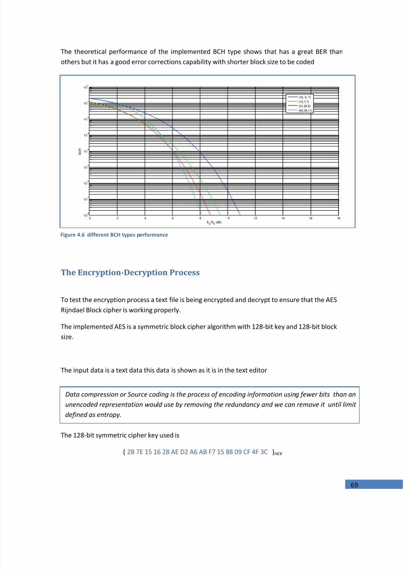
7/24/2019 Implementation of a Digital Communucation System A
http://slidepdf.com/reader/full/implementation-of-a-digital-communucation-system-a 69/98
69
0 2 4 6 8 10 12 14 16 1810
-8
10-7
10-6
10-5
10-4
10-3
10-2
10-1
100
Eb /N0 (dB)
B E R
(15, 5, 7)(15,7,7)(31,25,5)(63,36,11)
The theoretical performance of the implemented BCH type shows that has a great BER thanothers but it has a good error corrections capability with shorter block size to be coded
The Encryption-Decryption Process
To test the encryption process a text file is being encrypted and decrypt to ensure that the AESRijndael Block cipher is working properly.
The implemented AES is a symmetric block cipher algorithm with 128-bit key and 128-bit blocksize.
The input data is a text data this data is shown as it is in the text editor
The 128-bit symmetric cipher key used is
( 2B 7E 15 16 28 AE D2 A6 AB F7 15 88 09 CF 4F 3C)HEX
Figure 4.6 different BCH types performance
Data compression or Source coding is the process of encoding information using fewer bits than anunencoded representation would use by removing the redundancy and we can remove it until limitdefined as entropy.
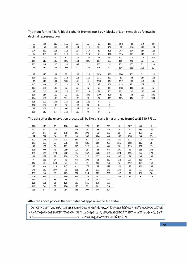
7/24/2019 Implementation of a Digital Communucation System A
http://slidepdf.com/reader/full/implementation-of-a-digital-communucation-system-a 70/98
70
The input for the AES RJ block cipher is broken into 4 by 4 blocks of 8-bit symbols as follows indecimal representation
The data after the encryption process will be like this and it has a range from 0 to 255 (0-FF)HEX
After the above process the text data that appears in the file editor
68 32 112 115
97 99 114 105
116 111 101 111
97 109 115 110
32 83 99 111
111 111 101 100
114 117 32 105
32 114 99 110
103 32 32 99
32 116 112 101
105 104 114 115
115 101 111 115
32 101 100 32
111 110 105 105
102 99 110 110
32 111 103 102
111 116 32 110
114 105 117 103
109 111 115 32
97 110 105 102
101 32 115 104
119 98 32 97
101 105 32 110
114 116 116 32
97 110 111 32
110 101 100 114
32 110 101 101
117 99 100 112
114 110 105 119
101 116 111 111
115 97 110 117
101 116 32 108
100 101 32 111
32 32 114 118
117 98 101 105
115 121 109 110
103 101 100 97
32 32 117 110
116 114 110 99
104 101 100 121
32 32 99 114
97 119 97 101
110 101 110 109
100 32 32 111
118 116 110 32
101 32 116 108
32 32 105 105
105 117 108 109
105 101 101 115
116 102 100 32
32 105 32 101
100 110 97 110
116 121 0 0
114 46 0 0
111 0 0 0
112 0 0 0
126 140 15 168 86 178 49 229 9 107 64 6
211 84 224 2 89 28 58 56 74 251 183 174
254 61 70 118 248 191 53 182 66 52 128 12
94 217 94 99 16 148 204 43 187 230 54 75
107 193 153 223 237 30 224 146 140 117 15 134
153 168 53 238 78 186 185 235 255 158 117 58
48 169 56 223 213 222 6 60 68 233 202 15
119 60 43 239 22 99 18 68 100 41 215 253
195 39 170 200 15 152 228 164 223 155 55 174
85 192 78 138 75 212 157 83 106 37 96 132
4 123 54 92 68 194 51 232 158 235 156 44
162 196 249 65 168 2 162 34 92 112 125 163
86 69 213 147 42 176 97 129 191 23 141 148
248 140 197 58 151 25 111 141 139 55 15 210
137 16 31 223 237 214 183 251 167 32 104 96
226 66 42 199 229 134 131 11 248 59 3 215
143 107 36 65 14 232 142 142
126 101 21 126 199 115 135 183
149 54 37 126 170 80 161 55
239 93 28 254 168 207 148 204
~Óþ^ŒT=ÙàF^¨vcVYø²¿”1:5Ìå8 JB»kû4æ@·€6®Kk™0wÁ¨©<™58 ß îßïíNÕ-ºÞc๒ë<DŒÿDdužé)uÊ׆:ýâ'À ĪN6ùÈŠ\AKD¨˜ÔÂä3¢¤Sè"ßjž\ ›%ëp7 œ̀}®„,£Vø‰âEŒBÕÅ*“:ßÇ*—íå°Ö†ao·ƒ • û ¿‹ ø7; h ”Ò`× ~•ï ke6]$%A~~þǪ¨èsPÏŽ‡¡”Ž·7Ì
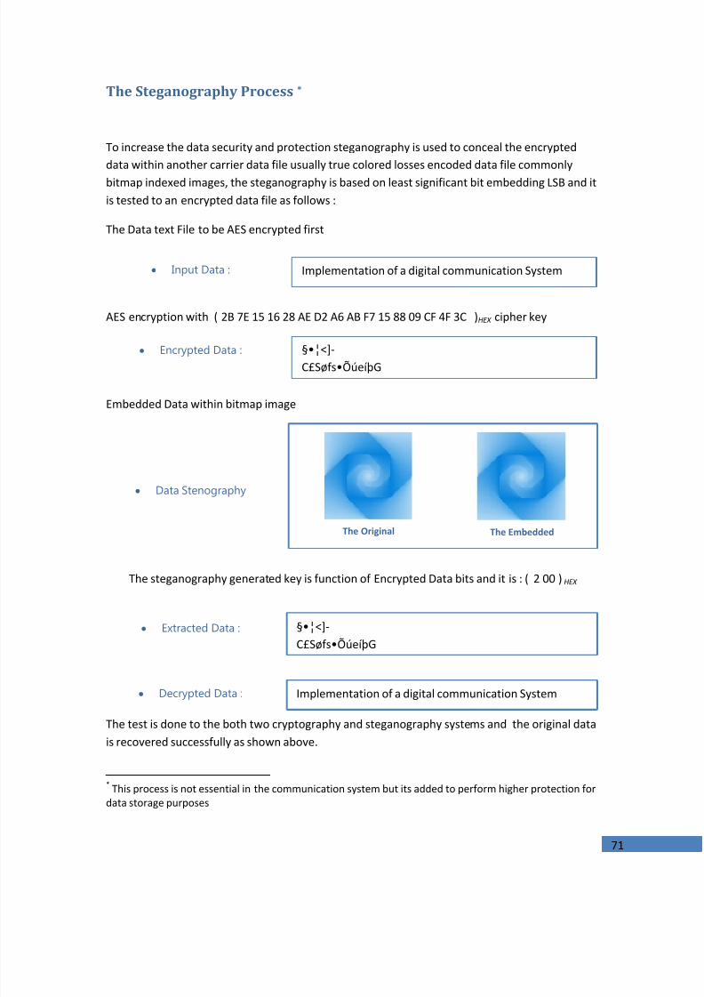
7/24/2019 Implementation of a Digital Communucation System A
http://slidepdf.com/reader/full/implementation-of-a-digital-communucation-system-a 71/98
71
The Steganography Process *
To increase the data security and protection steganography is used to conceal the encrypteddata within another carrier data file usually true colored losses encoded data file commonlybitmap indexed images, the steganography is based on least significant bit embedding LSB and itis tested to an encrypted data file as follows :
The Data text File to be AES encrypted first
AES encryption with (2B 7E 15 16 28 AE D2 A6 AB F7 15 88 09 CF 4F 3C)HEX cipher key
Embedded Data within bitmap image
The steganography generated key is function of Encrypted Data bits and it is : (2 00 ) HEX
The test is done to the both two cryptography and steganography systems and the original datais recovered successfully as shown above.
* This process is not essential in the communication system but its added to perform higher protection fordata storage purposes
Implementation of a digital communication SystemInput Data :
§•¦<]-C£Søfs ÕúeíþG
Encrypted Data :
The Original The Embedded
Data Stenography
§•¦<]-C£Søfs ÕúeíþG
Extracted Data :
Implementation of a digital communication SystemDecrypted Data :

7/24/2019 Implementation of a Digital Communucation System A
http://slidepdf.com/reader/full/implementation-of-a-digital-communucation-system-a 72/98
72
System Implementation
After each function is tested, the whole system functions have to work with each other toperform the total system operations.
The transmitter of the system has a data file as an input, this file is the source coder [bwtenc ] ,[ rundec ]or [ huffenc ] input, the output of this encoder is the compressed data file and it ispassed to AES encryption block[ AES( ) ] this block take the compressed binary file as a plain textand ciphers it after that the cipher text is encoded with FEC BCH (15, 5) encoder [bchen ] and itis modulated and transmitted over AWGN channel the channel function performs the lastoperation to the output BCH encoded file. For storage purposes the file can be protected withanother protection layer which is the steganography and it is done by the steganography systemthat is implemented to perform that.
The following diagram shows the steps described above
At the receiving side the data file is obtained by carrying out the reverse operations which arethe FEC BCH decoding [bchde ] then the decoded information is passed to the decryptionsystem to do the inverse operation of AES ciphering [iAES ] then the data is ready to bedecompressed by the source decoder [ bwtdec ], [huffdec ],or [ rundec ]If the data is concealed within a carrier file by the steganography system the data could beobtained by the inverse operation.The oerations above described in the next figure :
DataFile
SourceCoder
EncryptionSystem
Channel FECcoder
AWGNChannelSteganography
S stem
Figure 5 The Implemented System
Input coded
data
Cannel
Decoder
Decryption
System
Source
Decoder
DataFile
Figure 4.8 The implemented decoding system
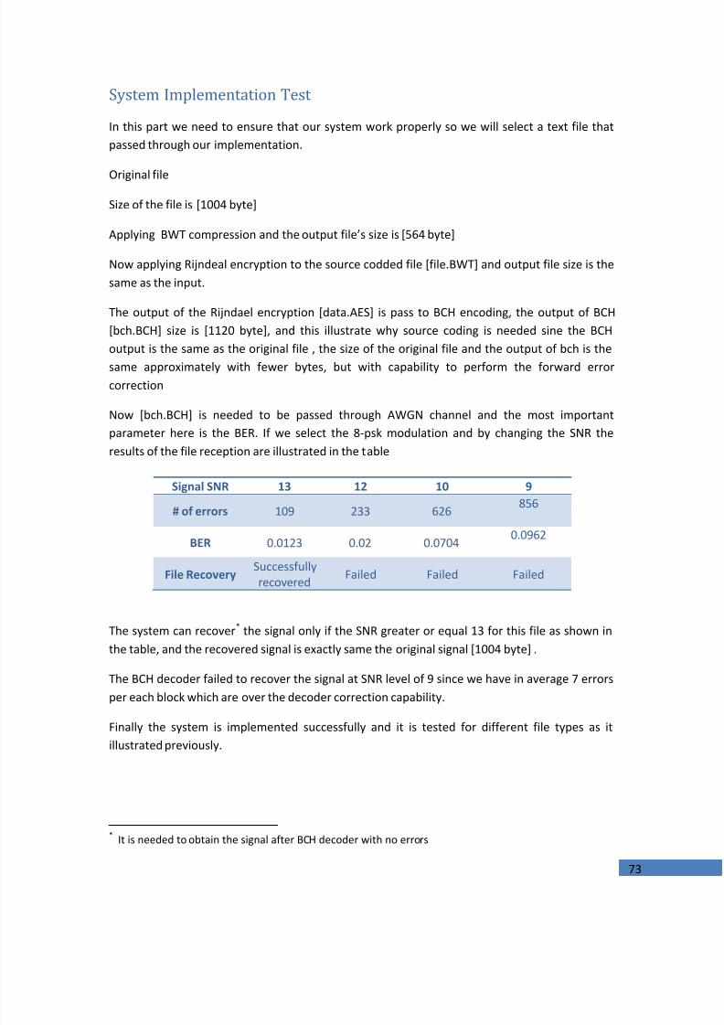
7/24/2019 Implementation of a Digital Communucation System A
http://slidepdf.com/reader/full/implementation-of-a-digital-communucation-system-a 73/98
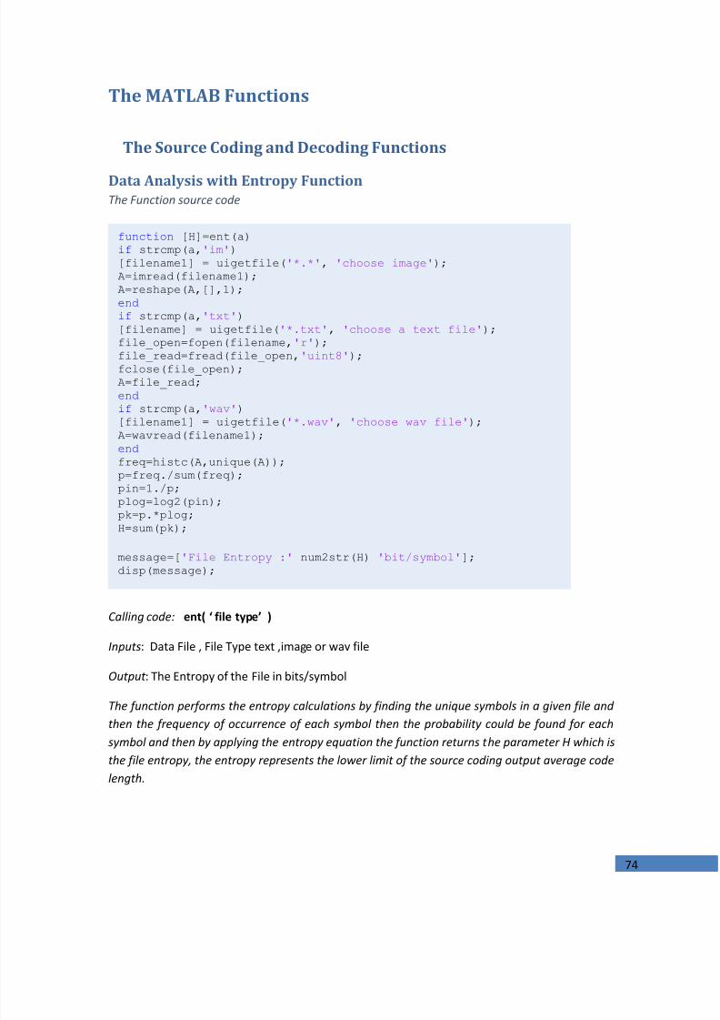
7/24/2019 Implementation of a Digital Communucation System A
http://slidepdf.com/reader/full/implementation-of-a-digital-communucation-system-a 74/98
74
The MATLAB Functions
The Source Coding and Decoding Functions
Data Analysis with Entropy FunctionThe Function source code
Calling code: ent( ‘ file type’ )
Inputs : Data File , File Type text ,image or wav file
Output : The Entropy of the File in bits/symbol
The function performs the entropy calculations by finding the unique symbols in a given file andthen the frequency of occurrence of each symbol then the probability could be found for eachsymbol and then by applying the entropy equation the function returns the parameter H which isthe file entropy, the entropy represents the lower limit of the source coding output average codelength.
function [H]=ent(a) if strcmp(a, 'im' ) [filename1] = uigetfile( '*.*' , 'choose image' ); A=imread(filename1); A=reshape(A,[],1); end if strcmp(a, 'txt' ) [filename] = uigetfile( '*.txt' , 'choose a text file' ); file_open=fopen(filename, 'r' ); file_read=fread(file_open, 'uint8' ); fclose(file_open); A=file_read; end if strcmp(a, 'wav' ) [filename1] = uigetfile( '*.wav' , 'choose wav file' ); A=wavread(filename1); end freq=histc(A,unique(A)); p=freq./sum(freq); pin=1./p; plog=log2(pin); pk=p.*plog; H=sum(pk);
message=[ 'File Entropy :' num2str(H) 'bit/symbol' ]; disp(message);

7/24/2019 Implementation of a Digital Communucation System A
http://slidepdf.com/reader/full/implementation-of-a-digital-communucation-system-a 75/98
75
Run-Length Encoder and DecoderThe Function source code
Calling code: runenc
Inputs : Data File
Output : Run-Length Encoded File (*.RUN )
The function reshapes the data file to a vector of symbols then it holds the symbol and counts therepetitions of that symbol after its position it takes another symbol when the different symbol is
found.
If there is no reputations in a given data file the size of this file will be increased as a result.
function []=runenc name=uigetfile( '*.*' ); file_open=fopen(name, 'r' ); file_read=fread(file_open, 'uint8' ); fclose(file_open); a=file_read; a=reshape(a,[],1); code=a; count=1;k=1;i=1; % Run Length Encoder while i~=length(code)
for j=i+1:length(code) if code(i)==code(j)
count=count+1;end if code(i)~=code(j)
Run_Len(k)=code(i); Run_Len(k+1)=count; k=k+2; count=1; i=j; break
end end
if j==length(code); Run_Len(k)=code(i);
Run_Len(k+1)=count; k=k+2; count=0; i=j;
break end
end file=fopen( 'File.RUN' , 'w' ); fwrite(file,Run_Len, 'ubit8' ); fclose(file);
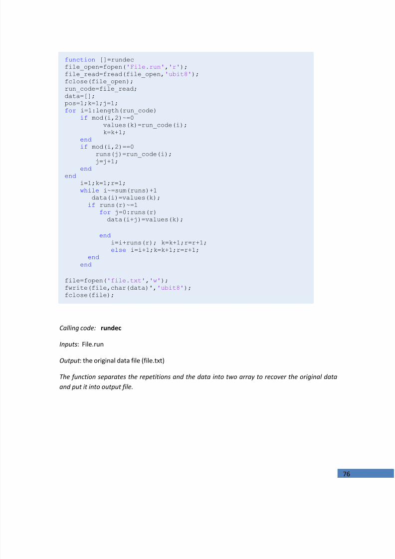
7/24/2019 Implementation of a Digital Communucation System A
http://slidepdf.com/reader/full/implementation-of-a-digital-communucation-system-a 76/98
76
Calling code: rundec
Inputs : File.run
Output : the original data file (file.txt)
The function separates the repetitions and the data into two array to recover the original dataand put it into output file.
function []=rundec file_open=fopen( 'File.run' , 'r' ); file_read=fread(file_open, 'ubit8' ); fclose(file_open); run_code=file_read; data=[]; pos=1;k=1;j=1; for i=1:length(run_code)
if mod(i,2)~=0 values(k)=run_code(i); k=k+1;
end if mod(i,2)==0
runs(j)=run_code(i); j=j+1;
end end
i=1;k=1;r=1; while i~=sum(runs)+1
data(i)=values(k); if runs(r)~=1
for j=0:runs(r) data(i+j)=values(k);
end i=i+runs(r); k=k+1;r=r+1; else i=i+1;k=k+1;r=r+1;
end end
file=fopen( 'file.txt' , 'w' ); fwrite(file,char(data)', 'ubit8' ); fclose(file);

7/24/2019 Implementation of a Digital Communucation System A
http://slidepdf.com/reader/full/implementation-of-a-digital-communucation-system-a 77/98

7/24/2019 Implementation of a Digital Communucation System A
http://slidepdf.com/reader/full/implementation-of-a-digital-communucation-system-a 78/98
78
Calling code: huffenc( )
Inputs : data file, type of file
Output : Huffman compressed file with header file contains the source symbols frequencies andlength of data ,The encoding and decoding is done as it was shown in chapter one
Huffman Decoder
Calling code: huffdnc( ) Inputs : huffman encoded file (*.huff),header files Output : data File
function []=huffdec(type) file_open=fopen( 'Key.HUFF' , 'r' ); file_read=fread(file_open, 'ubit8' ); fclose(file_open); [key]=file_read; power=key(1); sym=key(2); powerL=key(3); if strcmp(type, 'wav' )==1; file_open=fopen( 'DictS.HUFF' , 'r' ); file_read=fread(file_open, 'ubit8' ); fclose(file_open); symbols(1:sym)=file_read(1:sym); end if strcmp(type, 'wav' )==1; file_open=fopen( 'DictS.HUFF' , 'r' ); file_read=fread(file_open, 'double' ); fclose(file_open); symbols(1:sym)=file_read(1:sym); end file_open=fopen( 'DictF.HUFF' , 'r' ); command=[ 'ubit' int2str(power)]; file_read=fread(file_open,command); fclose(file_open); freq(1:sym)=file_read(1:sym); file_open=fopen( 'Len.HUFF' , 'r' ); commandL=[ 'ubit' int2str(powerL)]; file_read=fread(file_open,commandL); fclose(file_open); Len=file_read; file_open=fopen( 'File.HUFF' , 'r' ); file_read=fread(file_open, 'ubit1' ); fclose(file_open); hcode(1:Len)=file_read(1:Len); p(1:sym)=freq(1:sym)/sum(freq); dict = huffmandict(symbols,p); % Create the dictionary. dhsig = huffmandeco(hcode,dict); % Decode the code. if strcmp(type, 'wav' )==1; wavwrite(dhsig,44100, 'a.wav' ); end if strcmp(type, 'txt' )==1 file=fopen( 'file.txt' , 'w' ); fwrite(file,char(dhsig)', 'ubit8' ); fclose(file); end
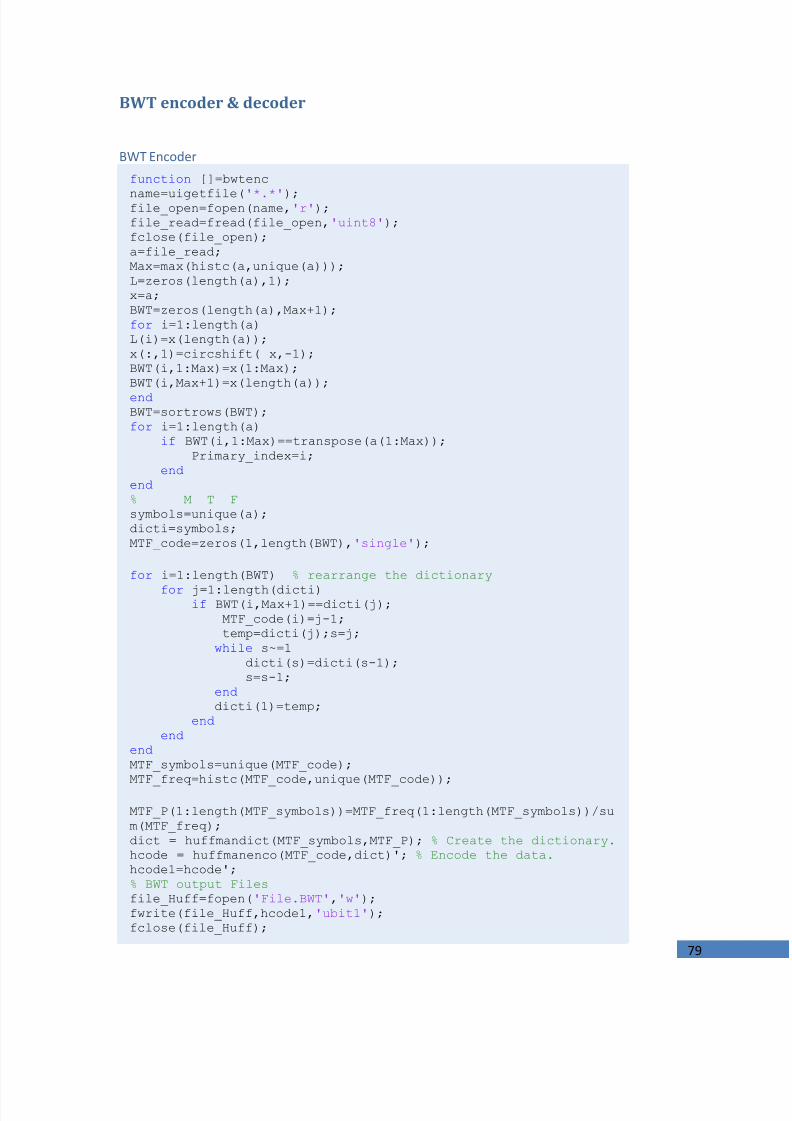
7/24/2019 Implementation of a Digital Communucation System A
http://slidepdf.com/reader/full/implementation-of-a-digital-communucation-system-a 79/98
79
BWT encoder & decoder
BWT Encoderfunction []=bwtenc name=uigetfile( '*.*' ); file_open=fopen(name, 'r' ); file_read=fread(file_open, 'uint8' ); fclose(file_open); a=file_read; Max=max(histc(a,unique(a))); L=zeros(length(a),1); x=a; BWT=zeros(length(a),Max+1); for i=1:length(a) L(i)=x(length(a)); x(:,1)=circshift( x,-1); BWT(i,1:Max)=x(1:Max); BWT(i,Max+1)=x(length(a)); end BWT=sortrows(BWT); for i=1:length(a)
if BWT(i,1:Max)==transpose(a(1:Max)); Primary_index=i;
end end % M T Fsymbols=unique(a); dicti=symbols; MTF_code=zeros(1,length(BWT), 'single' );
for i=1:length(BWT) % rearrange the dictionary for j=1:length(dicti) if BWT(i,Max+1)==dicti(j);
MTF_code(i)=j-1; temp=dicti(j);s=j;
while s~=1 dicti(s)=dicti(s-1); s=s-1;
end dicti(1)=temp;
end end
end MTF_symbols=unique(MTF_code);
MTF_freq=histc(MTF_code,unique(MTF_code)); MTF_P(1:length(MTF_symbols))=MTF_freq(1:length(MTF_symbols))/sum(MTF_freq); dict = huffmandict(MTF_symbols,MTF_P); % Create the dictionary. hcode = huffmanenco(MTF_code,dict)'; % Encode the data. hcode1=hcode'; % BWT output Files file_Huff=fopen( 'File.BWT' , 'w' ); fwrite(file_Huff,hcode1, 'ubit1' ); fclose(file_Huff);

7/24/2019 Implementation of a Digital Communucation System A
http://slidepdf.com/reader/full/implementation-of-a-digital-communucation-system-a 80/98
80
BWT Encoder con.
Calling code : bwtenc
Inputs : data file
Output : compressed file (*.BWT), header files contains MTF symbols & frequencies, Huffmansymbols, primary BWT index, source symbols.
powerL=1+ceil(log2(length(hcode))); commandL=[ 'ubit' int2str(powerL)]; Length_index=[length(hcode),Primary_index]; file_Huff=fopen( 'Length.BWT' , 'w' ); fwrite(file_Huff,Length_index,commandL); fclose(file_Huff);
powerMT=1+ceil(log2(max(MTF_symbols))); commandMT=[ 'ubit' int2str(powerMT)]; file_Huff=fopen( 'MTFSYM.MTF' , 'w' ); fwrite(file_Huff,MTF_symbols,commandMT); fclose(file_Huff);
power=1+ceil(log2(max(MTF_freq))); sym_no=length(MTF_freq); key=[power,sym_no,powerL,powerMT]; file_power=fopen( 'key' , 'w' ); fwrite(file_power,key, 'ubit8' ); fclose(file_power); file_Huff=fopen( 'MTF.MTF' , 'w' ); command=[ 'ubit' int2str(power)]; fwrite(file_Huff,MTF_freq,command); fclose(file_Huff);
file_Huff=fopen( 'Dict.MTF' , 'w' ); fwrite(file_Huff,symbols, 'ubit8' ); fclose(file_Huff);
AVL=0; for i=1:length(MTF_P)
AVL=AVL+MTF_P(i)*length(dict{i,2}); end

7/24/2019 Implementation of a Digital Communucation System A
http://slidepdf.com/reader/full/implementation-of-a-digital-communucation-system-a 81/98
81
BWT Decoder 3function []=bwtdec file_open=fopen( 'key' , 'r' ); file_read=fread(file_open, 'ubit8' ); fclose(file_open); [key1]=file_read; power1=key1(1,1);sym_no1=key1(2,1);powerL1=key1(3,1);powerMT1=key1(4,1); file_open=fopen( 'Dict.MTF' , 'r' ); file_read=fread(file_open, 'ubit8' ); fclose(file_open); [symbols1]=file_read; file_open=fopen( 'Length.BWT' , 'r' ); commandL1=[ 'ubit' int2str(powerL1)]; file_read=fread(file_open,commandL1); fclose(file_open); Length_huffcode=file_read(1); Primary_Index=file_read(2); file_open=fopen( 'File.BWT' , 'r' ); file_read=fread(file_open, 'ubit1' ); fclose(file_open); hcode1(1:Length_huffcode)=file_read(1:Length_huffcode); file_open=fopen( 'MTF.MTF' , 'r' ); command1=[ 'ubit' int2str(power1)]; file_read=fread(file_open,command1); fclose(file_open); MTF_freq1(1:sym_no1)=file_read(1:sym_no1); file_open=fopen( 'MTFSYM.MTF' , 'r' ); commandMT1=[ 'ubit' int2str(powerMT1)]; file_read=fread(file_open,commandMT1); fclose(file_open); MTF_symbols1(1:sym_no1)=file_read(1:sym_no1); MTF_P1(1:sym_no1)=MTF_freq1(1:sym_no1)/sum(MTF_freq1); %MTF_symbols1=unique(MTF_code); dict1 = huffmandict(MTF_symbols1,MTF_P1); % Create thedictionary. dhsig = huffmandeco(hcode1,dict1); % Decode the code.
IMTF_code=zeros(length(dhsig),1); for i=1:length(dhsig)
IMTF_code(i)=symbols1(dhsig(i)+1); s=dhsig(i)+1;
while s~=1 symbols1(s)=symbols1(s-1); s=s-1; end
symbols1(1)=IMTF_code(i); end % BWT decoding L=IMTF_code; F=zeros(length(L),2); F(:,1)=sortrows(L); T=zeros(length(L),1);

7/24/2019 Implementation of a Digital Communucation System A
http://slidepdf.com/reader/full/implementation-of-a-digital-communucation-system-a 82/98
82
BWT Decoder Con.
Calling code: bwtdec
Inputs : compressed file (*.BWT), header files
Output : original Data File
The encoding using BWT, MTF, and Huffman is discussed deeply in chapter one with thedecoding process .
This implementation has a good memory utilization for the process of storing the BWtransformed file since all permutations in done at separated variable and it is stored according tothe maximum frequency of occurrence of certain symbol so BWT matrix has a reduced size fromdata length by data length to maximum frequency plus one square. As a result, the block size
increased and the compression becomes more efficient.
for i=1:length(L) for j=1:length(F)
if (L(i)==F(j))&& (F(j,2)==0) T(i)=j; F(j,2)=1; break ; end
end end
S=zeros(length(L),1); % first step S(length(L))=L((Primary_Index)); X=T(Primary_Index); for i=1:length(L)-1
S(length(L)-i)=L(X); X=T(X);
end file_power=fopen( 'file.txt' , 'w' ); fwrite(file_power,char(S)', 'ubit8' ); fclose(file_power); message=[ 'AVL : ' num2str(AVL) 'bits/symbol' ]; disp(message)

7/24/2019 Implementation of a Digital Communucation System A
http://slidepdf.com/reader/full/implementation-of-a-digital-communucation-system-a 83/98
83
The Channel Coding and Decoding Function
BCH Encoderfunction []=bchen name=uigetfile( '*.*' ); file_open=fopen(name, 'r' ); file_read=fread(file_open, 'ubit1' ); fclose(file_open); a=file_read; n=input( 'Enter n: ' ); k=input( 'Enter k: ' ); P=input( 'Enter Generator polynomial: ' ); G=zeros(k,n); temp=zeros(1,n); temp(1,1:n-k+1)=P(1:length(P)); G(1,1:n)=temp(1:n); for i=2:k
temp = circshift(temp, [0, 1]); G(i,1:n)=temp(1:n);
end G=rem(abs(rref(G)),2); hh=length(a); for i=1:k-rem(hh ,k)
a(hh+i)=0; end j=1;m=k; jjj=length(a); output=zeros(1,jjj+jjj*10/k); for i=1:jjj/kinput1(j:m)=a(j:m); j=j+k; m=m+k; end f=1;h=k; x=1;x1=n; for i=1:(jjj/k)-1c=input1(f:h)*G; nn=1; for l=x:x1
output(l)=c(nn); nn=nn+1;
end x=x+n; x1=x1+n; f=f+k; h=h+k; end output=rem(output,2); file=fopen( 'bch.BCH' , 'w' ); fwrite(file,output, 'ubit1' ); fclose(file);

7/24/2019 Implementation of a Digital Communucation System A
http://slidepdf.com/reader/full/implementation-of-a-digital-communucation-system-a 84/98
84
Calling code: bchen Inputs : the binary file that is encoded by ‘huffenc ‘ or ‘bwtenc’ , Output :‘bch.BCH’
BCH Decoder
Calling code: bchde , Inputs : the encoded file ‘bch.BCH’ , Output : binary file ’ bchde.BCH’ thatwill be delivered to bwtdec or huffdec functions.
function []=bchde
name=uigetfile( '*.*' ); file_open=fopen(name, 'r' ); file_read=fread(file_open, 'ubit1' ); fclose(file_open); output=file_read; n=input( 'Enter n: ' ); k=input( 'Enter k: ' ); P=input( 'Enter Generator polynomial: ' ); G=zeros(k,n); temp=zeros(1,n); temp(1,1:n-k+1)=P(1:length(P)); G(1,1:n)=temp(1:n); for i=2:k
temp = circshift(temp, [0, 1]); G(i,1:n)=temp(1:n);
end G=rem(abs(rref(G)),2);
H=zeros(n-k,n); j=1; for i=k+1:n
H(j,k+j)=1; j=j+1;
end parity=G(:,k+1:n); H(:,1:k)=parity'; t = syndtable(H); j=1;m=n;u=1; for i=1:length(output)/nr(1:n)=output(j:m); s = rem(r * H', 2); err = bi2de(fliplr(s)); err_loc = t(err + 1, :); ccode = rem(err_loc + r, 2); recoverd(1,u:u+k-1)=ccode(1,1:k); u=u+k; j=j+n; m=m+n; end file=fopen( 'bchde.BCH' , 'w' ); fwrite(file,recoverd, 'ubit1' ); fclose(file);

7/24/2019 Implementation of a Digital Communucation System A
http://slidepdf.com/reader/full/implementation-of-a-digital-communucation-system-a 85/98
85
The Encryption FunctionsAES Rijndael
Rijndael encryption
This function needs another function which is [rjenc ] to perform the Rj. encryption algorithm
function []=AES(a) name=uigetfile( '*.*' );
file_open=fopen(name, 'r' ); file_read=fread(file_open, 'ubit8' ); fclose(file_open); data=file_read;
if strcmp(a, '1' )==1 file_open=fopen(name, 'r' ); file_read=fread(file_open, 'ubit1' ); fclose(file_open); data=file_read; end cipherkey=[43 40 171 9;126 174 247 207;21 210 21 79; 22 166 136
60;]; if strcmp(a, '1' )==1 data=reshape(data,8,[]); data=data'; data=bi2de(data, 'left-msb' ); end
k=16-(rem(length(data),16)); j=length(data);
for i=1:k data(j+i)=0;
end
enc_data=zeros(length(data),1); l=1; for i=1:length(data)/16
enc_data(l:l+15)=rjenc(cipherkey,data(l:l+15)); l=l+16;
end file=fopen( 'data.AES' , 'w' );
fwrite(file,enc_data, 'ubit8' ); fclose(file);
if strcmp(a, '1' )==1 enc_data=de2bi(enc_data, 'left-msb' ,8); enc_data=reshape(enc_data',[],1); file=fopen( 'data.AES' , 'w' ); fwrite(file,enc_data, 'ubit1' ); fclose(file); end
end
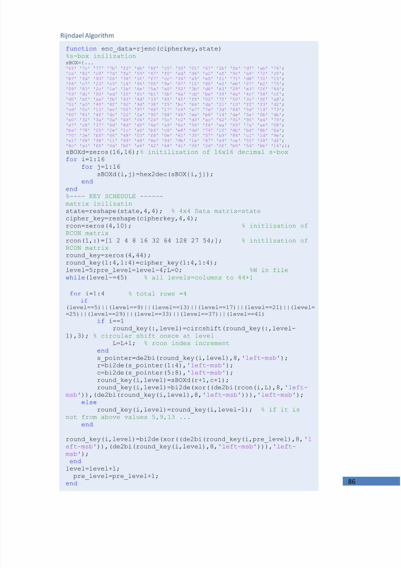
7/24/2019 Implementation of a Digital Communucation System A
http://slidepdf.com/reader/full/implementation-of-a-digital-communucation-system-a 86/98
86
function enc_data=rjenc(cipherkey,state) %s-box inilization sBOX={ ... '63' '7c' '77' '7b' 'f2' '6b' '6f' 'c5' '30' '01' '67' '2b' 'fe' 'd7' 'ab' '76' ; 'ca' '82' 'c9' '7d' 'fa' '59' '47' 'f0' 'ad' 'd4' 'a2' 'af' '9c' 'a4' '72' 'c0' ; 'b7' 'fd' '93' '26' '36' '3f' 'f7' 'cc' '34' 'a5' 'e5' 'f1' '71' 'd8' '31' '15' ; '04' 'c7' '23' 'c3' '18' '96' '05' '9a' '07' '12' '80' 'e2' 'eb' '27' 'b2' '75' ; '09' '83' '2c' '1a' '1b' '6e' '5a' 'a0' '52' '3b' 'd6' 'b3' '29' 'e3' '2f' '84' ; '53' 'd1' '00' 'ed' '20' 'fc' 'b1' '5b' '6a' 'cb' 'be' '39' '4a' '4c' '58' 'cf' ; 'd0' 'ef' 'aa' 'fb' '43' '4d' '33' '85' '45' 'f9' '02' '7f' '50' '3c' '9f' 'a8' ; '51' 'a3' '40' '8f' '92' '9d' '38' 'f5' 'bc' 'b6' 'da' '21' '10' 'ff' 'f3' 'd2' ; 'cd' '0c' '13' 'ec' '5f' '97' '44' '17' 'c4' 'a7' '7e' '3d' '64' '5d' '19' '73' ; '60' '81' '4f' 'dc' '22' '2a' '90' '88' '46' 'ee' 'b8' '14' 'de' '5e' '0b' 'db' ; 'e0' '32' '3a' '0a' '49' '06' '24' '5c' 'c2' 'd3' 'ac' '62' '91' '95' 'e4' '79' ; 'e7' 'c8' '37' '6d' '8d' 'd5' '4e' 'a9' '6c' '56' 'f4' 'ea' '65' '7a' 'ae' '08' ; 'ba' '78' '25' '2e' '1c' 'a6' 'b4' 'c6' 'e8' 'dd' '74' '1f' '4b' 'bd' '8b' '8a' ; '70' '3e' 'b5' '66' '48' '03' 'f6' '0e' '61' '35' '57' 'b9' '86' 'c1' '1d' '9e' ; 'e1' 'f8' '98' '11' '69' 'd9' '8e' '94' '9b' '1e' '87' 'e9' 'ce' '55' '28' 'df' ; '8c' 'a1' '89' '0d' 'bf' 'e6' '42' '68' '41' '99' '2d' '0f' 'b0' '54' 'bb' '16' ;};
sBOXd=zeros(16,16); % initilization of 16x16 decimal s-box for i=1:16
for j=1:16 sBOXd(i,j)=hex2dec(sBOX{i,j});
end end
%---- KEY SCHEDULE ------ matrix inilizatin state=reshape(state,4,4); % 4x4 Data matrix=state cipher_key=reshape(cipherkey,4,4); rcon=zeros(4,10); % initlization ofRCON matrix rcon(1,:)=[1 2 4 8 16 32 64 128 27 54;]; % initlization ofRCON matrix round_key=zeros(4,44); round_key(1:4,1:4)=cipher_key(1:4,1:4); level=5;pre_level=level-4;L=0; %W in file while (level~=45) % all levels=columns to 44+1
for i=1:4 % total rows =4 if
(level==5)||(level==9)||(level==13)||(level==17)||(level==21)||(level==25)||(level==29)||(level==33)||(level==37)||(level==41)
if i==1 round_key(:,level)=circshift(round_key(:,level-
1),3); % circular shift onece at level L=L+1; % rcon index increment
end s_pointer=de2bi(round_key(i,level),8, 'left-msb' ); r=bi2de(s_pointer(1:4), 'left-msb' ); c=bi2de(s_pointer(5:8), 'left-msb' ); round_key(i,level)=sBOXd(r+1,c+1); round_key(i,level)=bi2de(xor((de2bi(rcon(i,L),8, 'left-
msb' )),(de2bi(round_key(i,level),8, 'left-msb' ))), 'left-msb' ); else round_key(i,level)=round_key(i,level-1); % if it is
not from above values 5,9,13 ... end
round_key(i,level)=bi2de(xor((de2bi(round_key(i,pre_level),8, 'left-msb' )),(de2bi(round_key(i,level),8, 'left-msb' ))), 'left-msb' );
end level=level+1;
pre_level=pre_level+1; end
Rijndael Algorithm
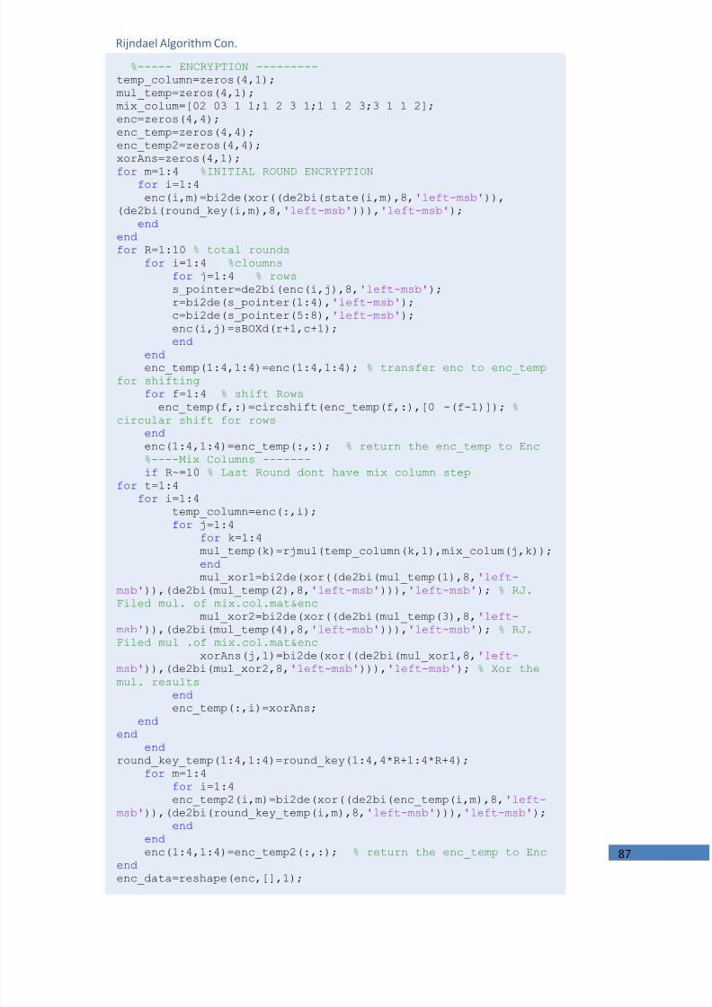
7/24/2019 Implementation of a Digital Communucation System A
http://slidepdf.com/reader/full/implementation-of-a-digital-communucation-system-a 87/98
87
%----- ENCRYPTION --------- temp_column=zeros(4,1); mul_temp=zeros(4,1); mix_colum=[02 03 1 1;1 2 3 1;1 1 2 3;3 1 1 2]; enc=zeros(4,4);enc_temp=zeros(4,4); enc_temp2=zeros(4,4); xorAns=zeros(4,1);
for m=1:4 %INITIAL ROUND ENCRYPTION for i=1:4 enc(i,m)=bi2de(xor((de2bi(state(i,m),8, 'left-msb' )),
(de2bi(round_key(i,m),8, 'left-msb' ))), 'left-msb' ); end
end for R=1:10 % total rounds
for i=1:4 %cloumns for j=1:4 % rowss_pointer=de2bi(enc(i,j),8, 'left-msb' ); r=bi2de(s_pointer(1:4), 'left-msb' ); c=bi2de(s_pointer(5:8), 'left-msb' ); enc(i,j)=sBOXd(r+1,c+1); end
end enc_temp(1:4,1:4)=enc(1:4,1:4); % transfer enc to enc_temp
for shifting for f=1:4 % shift Rows
enc_temp(f,:)=circshift(enc_temp(f,:),[0 -(f-1)]); %circular shift for rows
end enc(1:4,1:4)=enc_temp(:,:); % return the enc_temp to Enc %----Mix Columns ------- if R~=10 % Last Round dont have mix column step
for t=1:4for i=1:4
temp_column=enc(:,i);
for j=1:4 for k=1:4 mul_temp(k)=rjmul(temp_column(k,1),mix_colum(j,k)); end mul_xor1=bi2de(xor((de2bi(mul_temp(1),8, 'left-
msb' )),(de2bi(mul_temp(2),8, 'left-msb' ))), 'left-msb' ); % RJ.Filed mul. of mix.col.mat&enc
mul_xor2=bi2de(xor((de2bi(mul_temp(3),8, 'left-msb' )),(de2bi(mul_temp(4),8, 'left-msb' ))), 'left-msb' ); % RJ.Filed mul .of mix.col.mat&enc
xorAns(j,1)=bi2de(xor((de2bi(mul_xor1,8, 'left-msb' )),(de2bi(mul_xor2,8, 'left-msb' ))), 'left-msb' ); % Xor themul. results
end enc_temp(:,i)=xorAns;
end end
end round_key_temp(1:4,1:4)=round_key(1:4,4*R+1:4*R+4);
for m=1:4 for i=1:4 enc_temp2(i,m)=bi2de(xor((de2bi(enc_temp(i,m),8, 'left-
msb' )),(de2bi(round_key_temp(i,m),8, 'left-msb' ))), 'left-msb' ); end
end enc(1:4,1:4)=enc_temp2(:,:); % return the enc_temp to Enc
end enc_data=reshape(enc,[],1);
Rijndael Algorithm Con.

7/24/2019 Implementation of a Digital Communucation System A
http://slidepdf.com/reader/full/implementation-of-a-digital-communucation-system-a 88/98
88
These three function*‘AES’ , ‘rjenc’ , ‘rjmul’+ are working together to perform the encryptionprocess
Calling code: AES(‘Type’) Input : data file Output : encrypted file (*.AES)
Rijndael Decryption
also in decryption process we need two function to carry out the process
function [rj]=rjmul(a,b) apoly = gf(de2bi(a , 'left-msb' ),8,283);bpoly = gf(de2bi(b , 'left-msb' ),8,283); xpoly = gf([1 0 0 0 1 1 0 1 1],8,283);cpoly = conv(apoly,bpoly); [a2,remd] = deconv(cpoly,xpoly); rj=bi2de(double(remd.x), 'left-msb' );
function []=iAES name=uigetfile( '*.*' ); file_open=fopen(name, 'r' ); file_read=fread(file_open, 'ubit1' ); fclose(file_open); enc_data1=file_read; enc_data1=enc_data1'; enc_data1=reshape(enc_data1,8,[]); enc_data1=enc_data1'; enc_data1=bi2de(enc_data1, 'left-msb' ); enc_data=enc_data1; %k=length(enc_data1)-(rem(length(enc_data1),16)); %enc_data=enc_data1(1:k);
cipherkey=[43 40 171 9;126 174 247 207;21 210 21 79; 22 166 13660;];
data=zeros(length(enc_data),1); l=1; for i=1:length(data)/16
data(l:l+15)=rjdec(cipherkey,enc_data(l:l+15)); l=l+16;
end
data=de2bi(data, 'left-msb' ,8); data=data'; data=reshape(data,1,[]); file=fopen( 'data1.iAES' , 'w' ); fwrite(file,data, 'ubit1' );
Rijndael Field Multiplication , GF(8)
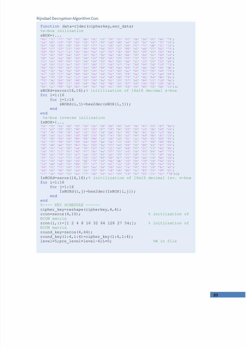
7/24/2019 Implementation of a Digital Communucation System A
http://slidepdf.com/reader/full/implementation-of-a-digital-communucation-system-a 89/98
89
function data=rjdec(cipherkey,enc_data) %s-box inilization sBOX={ ... '63' '7c' '77' '7b' 'f2' '6b' '6f' 'c5' '30' '01' '67' '2b' 'fe' 'd7' 'ab' '76' ;'ca' '82' 'c9' '7d' 'fa' '59' '47' 'f0' 'ad' 'd4' 'a2' 'af' '9c' 'a4' '72' 'c0' ;'b7' 'fd' '93' '26' '36' '3f' 'f7' 'cc' '34' 'a5' 'e5' 'f1' '71' 'd8' '31' '15' ;'04' 'c7' '23' 'c3' '18' '96' '05' '9a' '07' '12' '80' 'e2' 'eb' '27' 'b2' '75' ;'09' '83' '2c' '1a' '1b' '6e' '5a' 'a0' '52' '3b' 'd6' 'b3' '29' 'e3' '2f' '84' ;'53' 'd1' '00' 'ed' '20' 'fc' 'b1' '5b' '6a' 'cb' 'be' '39' '4a' '4c' '58' 'cf' ;'d0' 'ef' 'aa' 'fb' '43' '4d' '33' '85' '45' 'f9' '02' '7f' '50' '3c' '9f' 'a8' ;'51' 'a3' '40' '8f' '92' '9d' '38' 'f5' 'bc' 'b6' 'da' '21' '10' 'ff' 'f3' 'd2' ;'cd' '0c' '13' 'ec' '5f' '97' '44' '17' 'c4' 'a7' '7e' '3d' '64' '5d' '19' '73' ;'60' '81' '4f' 'dc' '22' '2a' '90' '88' '46' 'ee' 'b8' '14' 'de' '5e' '0b' 'db' ;'e0' '32' '3a' '0a' '49' '06' '24' '5c' 'c2' 'd3' 'ac' '62' '91' '95' 'e4' '79' ;'e7' 'c8' '37' '6d' '8d' 'd5' '4e' 'a9' '6c' '56' 'f4' 'ea' '65' '7a' 'ae' '08' ;'ba' '78' '25' '2e' '1c' 'a6' 'b4' 'c6' 'e8' 'dd' '74' '1f' '4b' 'bd' '8b' '8a' ;'70' '3e' 'b5' '66' '48' '03' 'f6' '0e' '61' '35' '57' 'b9' '86' 'c1' '1d' '9e' ;'e1' 'f8' '98' '11' '69' 'd9' '8e' '94' '9b' '1e' '87' 'e9' 'ce' '55' '28' 'df' ;'8c' 'a1' '89' '0d' 'bf' 'e6' '42' '68' '41' '99' '2d' '0f' 'b0' '54' 'bb' '16' ;};
sBOXd=zeros(16,16); % initilization of 16x16 decimal s-box for i=1:16
for j=1:16 sBOXd(i,j)=hex2dec(sBOX{i,j});
end end
%s-box inverse inilizationIsBOX={ ... '52' '09' '6a' 'd5' '30' '36' 'a5' '38' 'bf' '40' 'a3' '9e' '81' 'f3' 'd7' 'fb' ;'7c' 'e3' '39' '82' '9b' '2f' 'ff' '87' '34' '8e' '43' '44' 'c4' 'de' 'e9' 'cb' ;'54' '7b' '94' '32' 'a6' 'c2' '23' '3d' 'ee' '4c' '95' '0b' '42' 'fa' 'c3' '4e' ;'08' '2e' 'a1' '66' '28' 'd9' '24' 'b2' '76' '5b' 'a2' '49' '6d' '8b' 'd1' '25' ;'72' 'f8' 'f6' '64' '86' '68' '98' '16' 'd4' 'a4' '5c' 'cc' '5d' '65' 'b6' '92' ;'6c' '70' '48' '50' 'fd' 'ed' 'b9' 'da' '5e' '15' '46' '57' 'a7' '8d' '9d' '84' ;'90' 'd8' 'ab' '00' '8c' 'bc' 'd3' '0a' 'f7' 'e4' '58' '05' 'b8' 'b3' '45' '06' ;'d0' '2c' '1e' '8f' 'ca' '3f' '0f' '02' 'c1' 'af' 'bd' '03' '01' '13' '8a' '6b' ;'3a' '91' '11' '41' '4f' '67' 'dc' 'ea' '97' 'f2' 'cf' 'ce' 'f0' 'b4' 'e6' '73' ;'96' 'ac' '74' '22' 'e7' 'ad' '35' '85' 'e2' 'f9' '37' 'e8' '1c' '75' 'df' '6e' ;'47' 'f1' '1a' '71' '1d' '29' 'c5' '89' '6f' 'b7' '62' '0e' 'aa' '18' 'be' '1b' ;'fc' '56' '3e' '4b' 'c6' 'd2' '79' '20' '9a' 'db' 'c0' 'fe' '78' 'cd' '5a' 'f4' ;'1f' 'dd' 'a8' '33' '88' '07' 'c7' '31' 'b1' '12' '10' '59' '27' '80' 'ec' '5f' ;'60' '51' '7f' 'a9' '19' 'b5' '4a' '0d' '2d' 'e5' '7a' '9f' '93' 'c9' '9c' 'ef' ;'a0' 'e0' '3b' '4d' 'ae' '2a' 'f5' 'b0' 'c8' 'eb' 'bb' '3c' '83' '53' '99' '61' ;'17' '2b' '04' '7e' 'ba' '77' 'd6' '26' 'e1' '69' '14' '63' '55' '21' '0c' '7d' ;};IsBOXd=zeros(16,16); % initilization of 16x16 decimal inv. s-box for i=1:16 for j=1:16
IsBOXd(i,j)=hex2dec(IsBOX{i,j}); end
end %---- KEY SCHEDULE ------ cipher_key=reshape(cipherkey,4,4); rcon=zeros(4,10); % initlization ofRCON matrix rcon(1,:)=[1 2 4 8 16 32 64 128 27 54;]; % initlization ofRCON matrix round_key=zeros(4,44); round_key(1:4,1:4)=cipher_key(1:4,1:4); level=5;pre_level=level-4;L=0; %W in file
Rijndael Decryption Algorithm Con.

7/24/2019 Implementation of a Digital Communucation System A
http://slidepdf.com/reader/full/implementation-of-a-digital-communucation-system-a 90/98
90
while (level~=45) % all levels=columns to 44+1
for i=1:4 % total rows =4 if
(level==5)||(level==9)||(level==13)||(level==17)||(level==21)||(level==25)||(level==29)||(level==33)||(level==37)||(level==41)
if i==1 round_key(:,level)=circshift(round_key(:,level-
1),3); % circular shift onece at level L=L+1; % rcon index increment
end s_pointer=de2bi(round_key(i,level),8, 'left-msb' ); r=bi2de(s_pointer(1:4), 'left-msb' ); c=bi2de(s_pointer(5:8), 'left-msb' ); round_key(i,level)=sBOXd(r+1,c+1); round_key(i,level)=bi2de(xor((de2bi(rcon(i,L),8, 'left-
msb' )),(de2bi(round_key(i,level),8, 'left-msb' ))), 'left-msb' ); else
round_key(i,level)=round_key(i,level-1); % if it isnot from above values 5,9,13 ... end
round_key(i,level)=bi2de(xor((de2bi(round_key(i,pre_level),8, 'left-msb' )),(de2bi(round_key(i,level),8, 'left-msb' ))), 'left-msb' );
end level=level+1; pre_level=pre_level+1;
end %------DECRYPTION-------------- temp_column=zeros(4,1); mul_temp=zeros(4,1); mix_colum=[14 11 13 9;9 14 11 13;13 9 14 11;11 13 9 14];%inverse mix_colum encrypted_data=reshape(enc_data,4,4); state=zeros(4,4); enc_temp=zeros(4,4); enc_temp2=zeros(4,4); xorAns=zeros(4,1); enc=encrypted_data; for h=1:10 % total rounds
R=11-h; enc_temp2(:,:)=enc(:,:); % return the enc_temp to Enc %------ Add Round Key ------- round_key_temp(1:4,1:4)=round_key(1:4,4*R+1:4*R+4); for m=1:4 for i=1:4
enc_temp(i,m)=bi2de(xor((de2bi(enc_temp2(i,m),8, 'left-msb' )),(de2bi(round_key_temp(i,m),8, 'left-msb' ))), 'left-msb' );
end end enc(:,:)=enc_temp(:,:);
Rijndael Decryption Algorithm Con.

7/24/2019 Implementation of a Digital Communucation System A
http://slidepdf.com/reader/full/implementation-of-a-digital-communucation-system-a 91/98
91
%----Mix Columns ------- if R~=10 % Last Round dont have mix column step
for t=1:4for i=1:4
temp_column=enc(:,i); for j=1:4
for k=1:4
mul_temp(k)=rjmul(temp_column(k,1),mix_colum(j,k)); end mul_xor1=bi2de(xor((de2bi(mul_temp(1),8, 'left-
msb' )),(de2bi(mul_temp(2),8, 'left-msb' ))), 'left-msb' ); % RJ.Filed mul. of mix.col.mat&enc
mul_xor2=bi2de(xor((de2bi(mul_temp(3),8, 'left-msb' )),(de2bi(mul_temp(4),8, 'left-msb' ))), 'left-msb' ); % RJ.Filed mul .of mix.col.mat&enc
xorAns(j,1)=bi2de(xor((de2bi(mul_xor1,8, 'left-
msb' )),(de2bi(mul_xor2,8, 'left-msb' ))), 'left-msb' ); % Xor themul. results end enc_temp(:,i)=xorAns;
end end
end enc(:,:)=enc_temp(:,:); for f=1:4 % shift Rows
enc(f,:)=circshift(enc(f,:),[0 (f-1)]); % circular shiftfor rows
end for i=1:4 %cloumns
for j=1:4 % rowss_pointer=de2bi(enc(i,j),8, 'left-msb' ); r=bi2de(s_pointer(1:4), 'left-msb' ); c=bi2de(s_pointer(5:8), 'left-msb' ); enc(i,j)=IsBOXd(r+1,c+1); end
end end for m=1:4 %FINAL STEP
for i=1:4 state(i,m)=bi2de(xor((de2bi(enc(i,m),8, 'left-
msb' )),(de2bi(round_key(i,m),8, 'left-msb' ))), 'left-msb' ); end
end
data=reshape(state,[],1);
Rijndael Decryption Algorithm Con.

7/24/2019 Implementation of a Digital Communucation System A
http://slidepdf.com/reader/full/implementation-of-a-digital-communucation-system-a 92/98
92
These three function*‘iAES’ , ‘rjdec’ , ‘rjmul’+ that work together to perform the decryption part.
Calling code: i AES(‘Type’) , Inputs : encrypted file’data.AES’ ,Output :the decrypted file(‘data1.iAES’).
SteganographyLSB Steganography encoder
function []=textsteg(mode) [filename1,path] = uigetfile( '*.*' , 'choose the carrier' ); cd(path) carrierfile=imread(filename1); [filename] = uigetfile( '*.txt' , 'choose a file to beEmbedded' ); file_open=fopen(filename, 'r' ); file_read=fread(file_open, 'uint8' ); fclose(file_open); text=file_read;clear file_open ;clear file_read ; binary_text_bytes=de2bi(text,8); [tex_L,tex_W]=size(binary_text_bytes); [c_L,c_W,c_d]=size(carrierfile); binary_text=reshape(binary_text_bytes,[],1);
for i=1:length(binary_text) if mode==8pix_bi=de2bi(carrierfile(i),8, 'left-msb' ); pix_bi(8)=binary_text(i); %Least sig. bit 1st i=i+1; if i>length(binary_text), break ; end pix_bi(7)=binary_text(i-1); %Least sig. bit 2nd i=i+1; if i>length(binary_text), break ; end pix_bi(6)=binary_text(i-2); %Least sig. bit 3th i=i+1; if i>length(binary_text), break ; end pix_bi(5)=binary_text(i-3); %Least sig. bit 4th i=i+1; if i>length(binary_text), break ; end pix_bi(4)=binary_text(i-4); %Least sig. bit 5th i=i+1; if i>length(binary_text), break ; end pix_bi(3)=binary_text(i-5); %Least sig. bit 6th i=i+1; if i>length(binary_text), break ; end pix_bi(2)=binary_text(i-6); %Least sig. bit 7th
i=i+1; if i>length(binary_text), break ; end pix_bi(1)=binary_text(i-7); %Least sig. bit 8 th pix_val=bi2de(pix_bi, 'left-msb' ); carrierfile(i-7)=pix_val;end
if mode==7pix_bi=de2bi(carrierfile(i),8, 'left-msb' ); pix_bi(8)=binary_text(i); %Least sig. bit 1st i=i+1; if i>length(binary_text), break ; end pix_bi(7)=binary_text(i-1); %Least sig. bit 2nd i=i+1; if i>length(binary_text), break ; end pix_bi(6)=binary_text(i-2); %Least sig. bit 3th i=i+1; if i>length(binary_text), break ; end pix_bi(5)=binary_text(i-3); %Least sig. bit 4th i=i+1; if i>length(binary_text), break ; end pix_bi(4)=binary_text(i-4); %Least sig. bit 5th

7/24/2019 Implementation of a Digital Communucation System A
http://slidepdf.com/reader/full/implementation-of-a-digital-communucation-system-a 93/98
93
i=i+1; if i>length(binary_text), break ; end pix_bi(3)=binary_text(i-5); %Least sig. bit 6th i=i+1; if i>length(binary_text), break ; end pix_bi(2)=binary_text(i-6); %Least sig. bit 7th pix_val=bi2de(pix_bi, 'left-msb' ); carrierfile(i-6)=pix_val;
end if mode==6pix_bi=de2bi(carrierfile(i),8, 'left-msb' ); pix_bi(8)=binary_text(i); %Least sig. bit 1st i=i+1; if i>length(binary_text), break ; end pix_bi(7)=binary_text(i-1); %Least sig. bit 2nd i=i+1; if i>length(binary_text), break ; end pix_bi(6)=binary_text(i-2); %Least sig. bit 3th i=i+1; if i>length(binary_text), break ; end pix_bi(5)=binary_text(i-3); %Least sig. bit 4th i=i+1; if i>length(binary_text), break ; end pix_bi(4)=binary_text(i-4); %Least sig. bit 5th i=i+1; if i>length(binary_text), break ; end pix_bi(3)=binary_text(i-5); %Least sig. bit 6th pix_val=bi2de(pix_bi, 'left-msb' ); carrierfile(i-5)=pix_val;
end if mode==5pix_bi=de2bi(carrierfile(i),8, 'left-msb' ); pix_bi(8)=binary_text(i); %Least sig. bit 1st i=i+1; if i>length(binary_text), break ; end pix_bi(7)=binary_text(i-1); %Least sig. bit 2nd i=i+1; if i>length(binary_text), break ; end pix_bi(6)=binary_text(i-2); %Least sig. bit 3th i=i+1; if i>length(binary_text), break ; end pix_bi(5)=binary_text(i-3); %Least sig. bit 4th i=i+1; if i>length(binary_text), break ; end pix_bi(4)=binary_text(i-4); %Least sig. bit 5th pix_val=bi2de(pix_bi, 'left-msb' ); carrierfile(i-4)=pix_val;end if mode==4pix_bi=de2bi(carrierfile(i),8, 'left-msb' ); pix_bi(8)=binary_text(i); %Least sig. bit 1st i=i+1; if i>length(binary_text), break ; end pix_bi(7)=binary_text(i-1); %Least sig. bit 2nd i=i+1; if i>length(binary_text), break ; end pix_bi(6)=binary_text(i-2); %Least sig. bit 3th i=i+1; if i>length(binary_text), break ; end pix_bi(5)=binary_text(i-3); %Least sig. bit 4th pix_val=bi2de(pix_bi, 'left-msb' ); carrierfile(i-3)=pix_val;end if mode==3pix_bi=de2bi(carrierfile(i),8, 'left-msb' ); pix_bi(8)=binary_text(i); %Least sig. bit 1st i=i+1; if i>length(binary_text), break ; end pix_bi(7)=binary_text(i-1); %Least sig. bit 2nd i=i+1; if i>length(binary_text), break ; end pix_bi(6)=binary_text(i-2); %Least sig. bit 3th pix_val=bi2de(pix_bi, 'left-msb' ); carrierfile(i-2)=pix_val;end

7/24/2019 Implementation of a Digital Communucation System A
http://slidepdf.com/reader/full/implementation-of-a-digital-communucation-system-a 94/98
94
Calling code: textsteg (‘mode’) , Inputs : the carrier file [picture] and the text file to beembedded , Output : ‘'Steg-image-with-text.bmp’
LSB Steganography decoder
if mode==2pix_bi=de2bi(carrierfile(i),8, 'left-msb' ); pix_bi(8)=binary_text(i); %Least sig. bit 1st
i=i+1; if i>length(binary_text), break ; end pix_bi(7)=binary_text(i-1); %Least sig. bit 2nd
pix_val=bi2de(pix_bi, 'left-msb' ); carrierfile(i-1)=pix_val;
end if mode==1pix_bi=de2bi(carrierfile(i),8, 'left-msb' ); pix_bi(8)=binary_text(i); %Least sig. bit 1st
pix_val=bi2de(pix_bi, 'left-msb' ); carrierfile(i)=pix_val;end
end
imwrite(carrierfile, 'Steg-image-with-text.bmp' ); A=num2str(length(binary_text)); out_data=[ 'The Key For Extracting The Data is : ' ,A];
file=fopen( 'Key.txt' , 'w' ); fwrite(file,out_data, 'uint8' ); fclose(file); figure imshow(carrierfile);clc;message=[ 'DONE With carrier:' ,filename1, ' to text file :' ,filename, ' the key is :' ,A ]; disp(message);disp( 'M.H & M.A' );
function []=textstegde(mode) Key=input( 'enter the key :' ); a=uigetfile( '*.bmp' , 'choose stego-image with text' ); carrierfile_Em=imread(a); binary_text_reconstructed=zeros(1,Key); for i=1:Key
tt=i; if mode==8
pix_bi=de2bi(carrierfile_Em(i),8, 'left-msb' ); binary_text_reconstructed(i)=pix_bi(8); i=i+1; if i>Key, break ; end %Least sig. bit 2 binary_text_reconstructed(i)=pix_bi(7);
i=i+1; if i>Key, break ; end %Least sig. bit 3 binary_text_reconstructed(i)=pix_bi(6); i=i+1; if i>Key, break ; end %Least sig. bit 4 binary_text_reconstructed(i)=pix_bi(5); i=i+1; if i>Key, break ; end %Least sig. bit 5 binary_text_reconstructed(i)=pix_bi(4); i=i+1; if i>Key, break ; end %Least sig. bit 6 binary_text_reconstructed(i)=pix_bi(3); i=i+1; if i>Key, break ; end %Least sig. bit 7 binary_text_reconstructed(i)=pix_bi(2); i=i+1; if i>Key, break ; end %Least sig. bit 8 binary_text_reconstructed(i)=pix_bi(1);
end

7/24/2019 Implementation of a Digital Communucation System A
http://slidepdf.com/reader/full/implementation-of-a-digital-communucation-system-a 95/98
95
if mode==7 pix_bi=de2bi(carrierfile_Em(i),8, 'left-msb' ); binary_text_reconstructed(i)=pix_bi(8); i=i+1; if i>Key, break ; end %Least sig. bit 2 binary_text_reconstructed(i)=pix_bi(7);
i=i+1; if i>Key, break ; end %Least sig. bit 3 binary_text_reconstructed(i)=pix_bi(6);
i=i+1; if i>Key, break ; end %Least sig. bit 4 binary_text_reconstructed(i)=pix_bi(5);
i=i+1; if i>Key, break ; end %Least sig. bit 5 binary_text_reconstructed(i)=pix_bi(4);
i=i+1; if i>Key, break ; end %Least sig. bit 6 binary_text_reconstructed(i)=pix_bi(3); i=i+1; if i>Key, break ; end %Least sig. bit 7 binary_text_reconstructed(i)=pix_bi(2);
end if mode==6
pix_bi=de2bi(carrierfile_Em(i),8, 'left-msb' ); binary_text_reconstructed(i)=pix_bi(8); i=i+1; if i>Key, break ; end %Least sig. bit 2 binary_text_reconstructed(i)=pix_bi(7); i=i+1; if i>Key, break ; end %Least sig. bit 3 binary_text_reconstructed(i)=pix_bi(6);
i=i+1; if i>Key, break ; end %Least sig. bit 4 binary_text_reconstructed(i)=pix_bi(5);
i=i+1; if i>Key, break ; end %Least sig. bit 5 binary_text_reconstructed(i)=pix_bi(4);
i=i+1; if i>Key, break ; end %Least sig. bit 6 binary_text_reconstructed(i)=pix_bi(3);
end if mode==5
pix_bi=de2bi(carrierfile_Em(i),8, 'left-msb' ); binary_text_reconstructed(i)=pix_bi(8); i=i+1; if i>Key, break ; end %Least sig. bit 2 binary_text_reconstructed(i)=pix_bi(7);
i=i+1; if i>Key, break ; end %Least sig. bit 3 binary_text_reconstructed(i)=pix_bi(6);
i=i+1; if i>Key, break ; end %Least sig. bit 4 binary_text_reconstructed(i)=pix_bi(5);
i=i+1; if i>Key, break ; end %Least sig. bit 5 binary_text_reconstructed(i)=pix_bi(4);
end
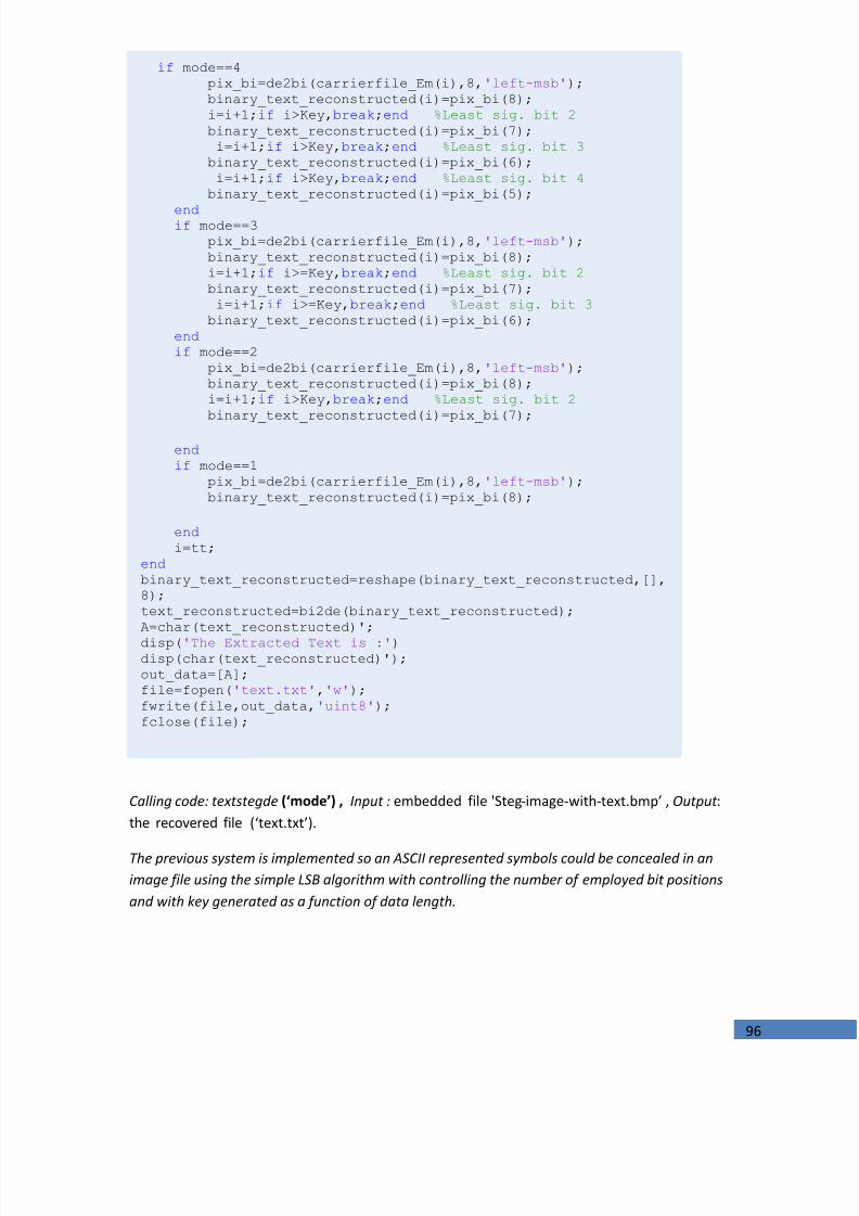
7/24/2019 Implementation of a Digital Communucation System A
http://slidepdf.com/reader/full/implementation-of-a-digital-communucation-system-a 96/98
96
Calling code: textstegde (‘mode’) , Input : embedded file 'Steg-image-with-text.bmp’ , Output :the recovered file (‘text.txt’).
The previous system is implemented so an ASCII represented symbols could be concealed in animage file using the simple LSB algorithm with controlling the number of employed bit positionsand with key generated as a function of data length.
if mode==4 pix_bi=de2bi(carrierfile_Em(i),8, 'left-msb' ); binary_text_reconstructed(i)=pix_bi(8); i=i+1; if i>Key, break ; end %Least sig. bit 2 binary_text_reconstructed(i)=pix_bi(7);
i=i+1; if i>Key, break ; end %Least sig. bit 3 binary_text_reconstructed(i)=pix_bi(6);
i=i+1; if i>Key, break ; end %Least sig. bit 4 binary_text_reconstructed(i)=pix_bi(5);
end if mode==3 pix_bi=de2bi(carrierfile_Em(i),8, 'left-msb' ); binary_text_reconstructed(i)=pix_bi(8); i=i+1; if i>=Key, break ; end %Least sig. bit 2 binary_text_reconstructed(i)=pix_bi(7);
i=i+1; if i>=Key, break ; end %Least sig. bit 3 binary_text_reconstructed(i)=pix_bi(6);
end if mode==2
pix_bi=de2bi(carrierfile_Em(i),8, 'left-msb' ); binary_text_reconstructed(i)=pix_bi(8); i=i+1; if i>Key, break ; end %Least sig. bit 2 binary_text_reconstructed(i)=pix_bi(7);
end if mode==1
pix_bi=de2bi(carrierfile_Em(i),8, 'left-msb' ); binary_text_reconstructed(i)=pix_bi(8);
end i=tt;
end binary_text_reconstructed=reshape(binary_text_reconstructed,[],8); text_reconstructed=bi2de(binary_text_reconstructed); A=char(text_reconstructed)'; disp( 'The Extracted Text is :' ) disp(char(text_reconstructed)'); out_data=[A]; file=fopen( 'text.txt' , 'w' ); fwrite(file,out_data, 'uint8' ); fclose(file);

7/24/2019 Implementation of a Digital Communucation System A
http://slidepdf.com/reader/full/implementation-of-a-digital-communucation-system-a 97/98
97
The Channel and Modulation function
MATLAB performs the modulation and demodulation process and AWGN channel modeling bythe functions [awgn() ] and [pskmod ] .
Calling code: noisych ( modulation order , SNR)
Input : BCH coded file (*.BCH)
Output : BCH file with white Gaussian noise added.
function []=noisych(M,snr)
name=uigetfile( '*.*' ); file_open=fopen(name, 'r' ); file_read=fread(file_open, 'ubit1' ); fclose(file_open); output=file_read;
sig=pskmod(output,M); rsig=awgn(sig,snr); dsig=pskdemod(rsig,M);
file=fopen( 'noisych.CH' , 'w' ); fwrite(file,dsig, 'ubit1' ); fclose(file);
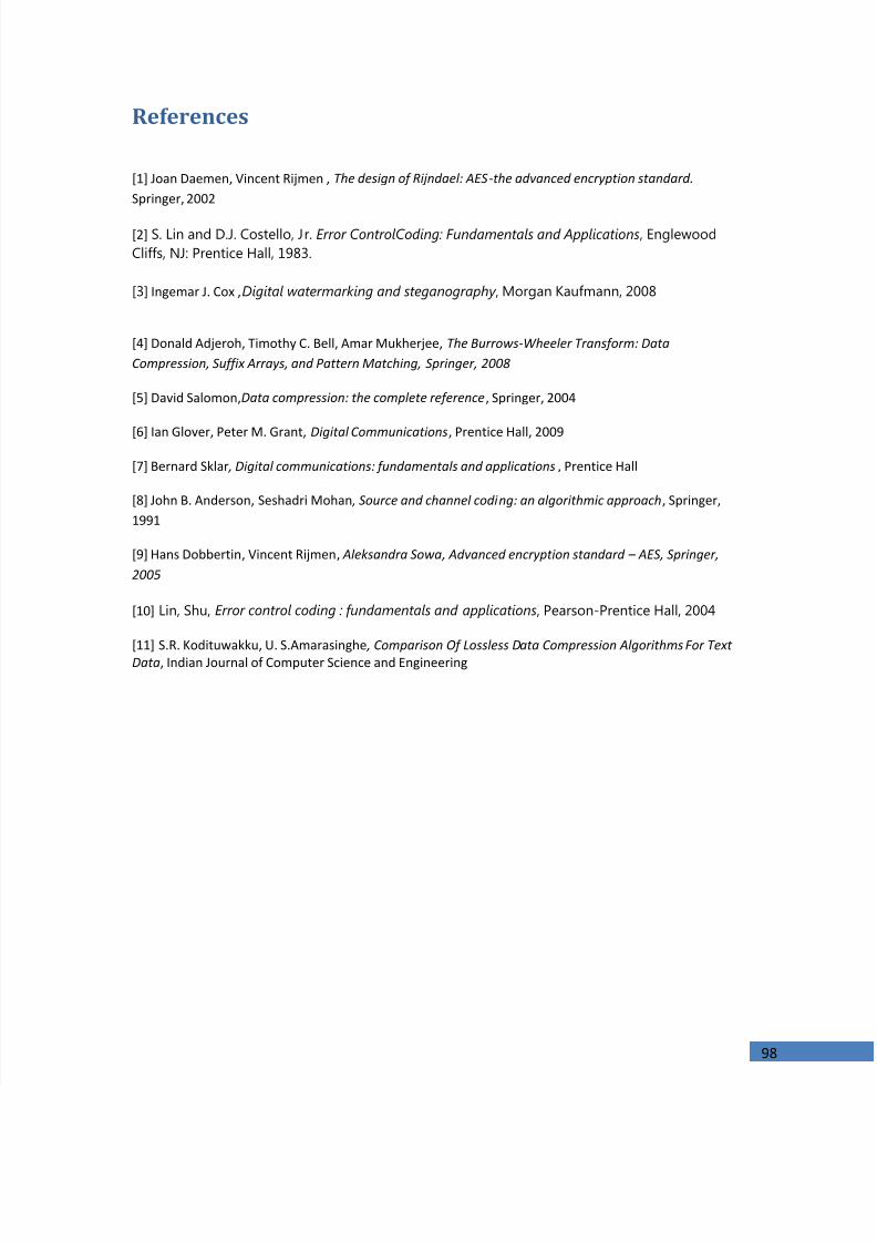
7/24/2019 Implementation of a Digital Communucation System A
http://slidepdf.com/reader/full/implementation-of-a-digital-communucation-system-a 98/98
References
[1] Joan Daemen, Vincent Rijmen ,The design of Rijndael: AES-the advanced encryption standard. Springer, 2002
[2] S. Lin and D.J. Costello, Jr. Error ControlCoding: Fundamentals and Applications , EnglewoodCliffs, NJ: Prentice Hall, 1983.
[3] Ingemar J. Cox ,Digital watermarking and steganography , Morgan Kaufmann, 2008
[4] Donald Adjeroh, Timothy C. Bell, Amar Mukherjee,The Burrows-Wheeler Transform: DataCompression, Suffix Arrays, and Pattern Matching, Springer, 2008
[5] David Salomon,Data compression: the complete reference , Springer, 2004
[6] Ian Glover, Peter M. Grant,Digital Communications , Prentice Hall, 2009[7] Bernard Sklar , Digital communications: fundamentals and applications , Prentice Hall
[8] John B. Anderson, Seshadri Mohan , Source and channel coding: an algorithmic approach , Springer,1991
[9] Hans Dobbertin , Vincent Rijmen , Aleksandra Sowa , Advanced encryption standard – AES, Springer,
2005
[10] Lin, Shu, Error control coding : fundamentals and applications , Pearson-Prentice Hall, 2004
[11] S.R. Kodituwakku, U. S.Amarasinghe , Comparison Of Lossless Data Compression Algorithms For TextData , Indian Journal of Computer Science and Engineering