Embed Size (px)
Citation preview
BULETINUL INSTITUTULUI POLITEHNIC DIN IAŞI
Publicat de
Universitatea Tehnică „Gheorghe Asachi” din Iaşi
Volumul 66 (70), Numărul 1, 2020
Secţia
ELECTROTEHNICĂ. ENERGETICĂ. ELECTRONICĂ
IMPLEMENTATION ISSUES FOR ONE-STEP-AHEAD
PREDICTIVE CONTROL OF AN INDUCTION MACHINE
BY
MĂDĂLIN COSTIN1,2,
1“Gheorghe Asachi” Technical University of Iași,
Faculty of Automatic Control and Computer Science 2“Dunărea de Jos” University of Galaţi, Faculty of Automatic Control,
Computer Science, Electrical and Electronics Engineering
Received: October 23, 2020
Accepted for publication: December 8, 2020
Abstract. In this paper is presented the algorithm in pseudo-code format
for one-step-ahead predictive control of induction machine. For this propose, it is
developed the mathematical model of induction machine in a stationary system
reference frame. The Model Predictive Control (MPC) of induction machine is a
problem of cost function optimization that leads to finding the optimal switching
functions of the power inverter. Electromagnetic torque and stator magnetic flux
are controlled by predictive controller in the order to meet the references. The
obtained results by simulation in Matlab-Simulink® environment of torque and
speed confirm the desired control performances by tracking the references. It is
concluded that due to the obtained performances, MPC of induction machine
represents an alternative to the classical methods. The developing of algorithms
for prediction in induction machine drive is a fundamental task for the modern
approach by integrating and implementing of advanced control strategies.
Keywords: one-step-ahead predictive control; induction machine;
switching functions; pseudo-code format; predictive controller; speed response.
Corresponding author; e-mail: [email protected]
74 Mădălin Costin
1. Introduction
Actually, an important attention is accorded to developing of electric
drives with induction machine. The main advantages that recommends
induction machine in such applications are (Boldea and Nasar, 2009): low cost,
high torque capability, robust structure, well-developed manufactures
technology with low environment impact and minimum waste of materials. As a
consequence of the power converters and advanced signal processors
developing, induction machine has been embedded in a large area of
applications (Boldea and Nasar, 2005; Leonhard, 2001): electric drives with
adjustable speed, motion control in robotics, automotive applications, electric
railways, industrial process, special applications etc.
The control of induction machine has been developed by separating the
flux and electromagnetic torque loops as is natural achieved at Direct Current
(DC) electric machines. Nevertheless, a global theory of orthogonal models
starting for synchronous machine (Park, 1929; Park 1933) and later has been
developed for induction machine (Ku, 1957). A first approach of closed loop
control theory of induction machine was based on magnetic flux sensors
(Blaschke, 1972), called direct method. The proposed novelty is the concept of
transvector theory that means the mathematical model of electric machine is
oriented in a particular system reference frame aligned to magnetic flux. The
highest performances were obtained for rotor magnetic flux orientation. In this
case, the mathematical model of control systems is simplified and an easy-
implementation control strategy may be performed (Boldea and Nasar, 2005).
In the order to eliminate the difficulties generated by using the magnetic
flux sensors, which involves the increasing of costs and signal perturbation, an
indirect method of field oriented control was suggested by (Hasse, 1969) and
included later in closed loop applications (Matsuo and Lipo, 1985). In this case,
the magnetic flux is computed with the help of stator currents and angular
speed. The later works proposed a substantial improvement of the closed-loop
performances that leads to using different computational techniques. Due to the
large area of applications, these results become classical, and are currently used
as an essential tool for modeling and control loop design (Leonhard, 2001;
Quang and Dittrich, 2008). More advanced control techniques propose the
elimination of mechanical sensor, the speed being estimated in so-called
sensorless control methods (Vas, 1998).
A particular class of control strategy is represented by Direct Torque
Control (DTC). In this case, the mathematical model of induction machine is
represented in stator coordinates, the motor being non-aligned with magnetic
flux. The advantage is the simplification of control scheme which are
implemented with bang-bang controllers, while the drawback is the high values
of the ripple of electromagnetic torque (Vas, 1998; Depenbrock, 1984).
The interface between control system and induction machine is assured
Bul. Inst. Polit. Iaşi, Vol. 66 (70), Nr. 1, 2020 75
by the execution element which is represented by a power inverter that is
controlled by signal controllers. The output voltage is obtained based on a
modulation of control signals which is designed according to different criteria
(Kerkman, 1996). Due to signals processing, the usual modulation techniques
are quite complex.
A survey of the control methods of Alternative Current (AC) drives,
including induction machine, is represented by (Haitham et al., 2012). Also,
there are presented additional information for user in implementation on
Matlab-Simulink ® environment, which are in the current trend.
In parallel with the classic induction machine control strategy
development, prediction in various processes for control systems was present in
the researcher’s attention (Maciejowski, 2002). From a large area of methods, a
practice and deterministic method are represented by MPC (Camacho and
Bordons, 2004; Rawlings and Mayne, 2009; Rossiter, 2013). Due to the fact
that the mathematical model of induction machine is well-known, the MPC may
be successfully applied.
A first approach of MPC of induction machine has been performed in
the last decades (Kennel and Linder, 2000; Kennel and Linder, 2001; Geyer,
2005), and later improved for practical applications (Tibamoso and Oñate,
2017). May be used continuous or continuous MPC controllers (Wróbel et al.,
2020). The benefits arise from using MPC in the induction machine drive are:
optimization of both transients and steady-state regimes, avoiding the tuning of
controllers as in the case of classic methods, easy-including the restriction of
control signals, prediction in a predefined horizon etc.
A simplification MPC of induction machine can be developed by
considering the induction machine supplied by a power inverter. The
mathematical model of the inverter is built up based on six switching discrete
functions, which by a linear combination may provide the command voltage of
induction machine (Rodriguez and Cortes, 2012). In this case, the MPC of
induction machine leads to a particular and a simple block scheme that is very
useful for practice. At every time instant it is searched the optimal values of
switching function that composed the desired control reference voltage. By
including the mathematical model of the power inverter, the approach fits the
real situation that occurs in practice, which leads to harmonic content on the
output voltage of the inverter, and ripple of electromagnetic torque of induction
machine. In some ways, the principle of this control strategy derives from DTC,
but the major difference is that the switching state results as an optimization
process, and not a forced range limitations as is used on DTC.
In recent years, an important effort is based on developing high
performance systems with digital controllers. The advance of the numerical
processors and digital signal technique allows a friendly implementation in both
online and off-line systems. For this objective it is essential to perform
numerical algorithms that may be implemented on emerging technologies.
76 Mădălin Costin
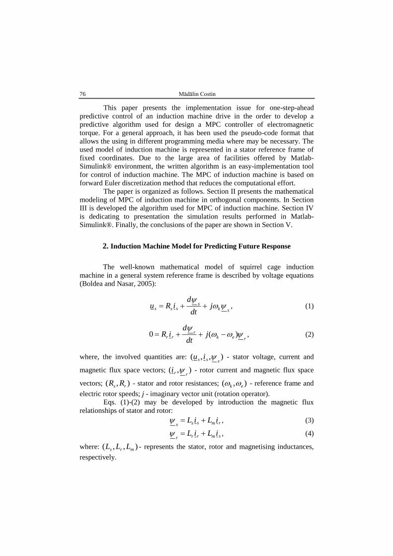
This paper presents the implementation issue for one-step-ahead
predictive control of an induction machine drive in the order to develop a
predictive algorithm used for design a MPC controller of electromagnetic
torque. For a general approach, it has been used the pseudo-code format that
allows the using in different programming media where may be necessary. The
used model of induction machine is represented in a stator reference frame of
fixed coordinates. Due to the large area of facilities offered by Matlab-
Simulink® environment, the written algorithm is an easy-implementation tool
for control of induction machine. The MPC of induction machine is based on
forward Euler discretization method that reduces the computational effort.
The paper is organized as follows. Section II presents the mathematical
modeling of MPC of induction machine in orthogonal components. In Section
III is developed the algorithm used for MPC of induction machine. Section IV
is dedicating to presentation the simulation results performed in Matlab-
Simulink®. Finally, the conclusions of the paper are shown in Section V.
2. Induction Machine Model for Predicting Future Response
The well-known mathematical model of squirrel cage induction
machine in a general system reference frame is described by voltage equations
(Boldea and Nasar, 2005):
sks
sss jdt
diRu
, (1)
rekr
rr jdt
diR
)(0 , (2)
where, the involved quantities are: ),,(sss iu - stator voltage, current and
magnetic flux space vectors; ),(rri - rotor current and magnetic flux space
vectors; ),( rs RR - stator and rotor resistances; ),( ek - reference frame and
electric rotor speeds; j - imaginary vector unit (rotation operator).
Eqs. (1)-(2) may be developed by introduction the magnetic flux
relationships of stator and rotor:
rmsssiLiL , (3)
smrrriLiL , (4)
where: ),,( mrs LLL - represents the stator, rotor and magnetising inductances,
respectively.
Bul. Inst. Polit. Iaşi, Vol. 66 (70), Nr. 1, 2020 77
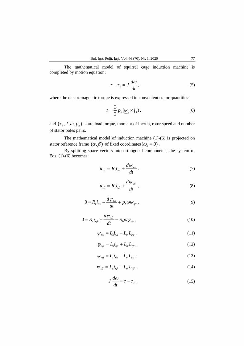
The mathematical model of squirrel cage induction machine is
completed by motion equation:
dt
dJ
, (5)
where the electromagnetic torque is expressed in convenient stator quantities:
)(2
3ssb ip , (6)
and ),,,( bpJ - are load torque, moment of inertia, rotor speed and number
of stator poles pairs.
The mathematical model of induction machine (1)-(6) is projected on
stator reference frame ),( of fixed coordinates )0( k .
By splitting space vectors into orthogonal components, the system of
Eqs. (1)-(6) becomes:
dt
diRu ssss
, (7)
dt
diRu
s
sss
, (8)
sbr
rr pdt
diR 0 , (9)
sb
r
rr pdt
diR 0 , (10)
rmsss LLiL , (11)
rmsss LLiL , (12)
rmrrr LLiL , (13)
rmrrr LLiL , (14)
dt
dJ , (15)
78 Mădălin Costin
)(2
3 ssssb iip , (16)
where the electric speed is replaced by mechanical one with respect the relation
be p .
The interface between power sources and induction machine is assured
by power inverter which converters the DC into AC voltage. Also, the inverter
represents the gate between power part and the signal one of the system. It is
fundamental to describe the mathematical model of the inverter in a compatible
mode with control system applications. A simple and useful mathematical
model is based on switching function (Leonhard, 2001), which associates to
each switch a logic Boolean value. It is considered that the input voltage of
power inverter, named DC-link voltage, has a constant value .cstUDC Thus,
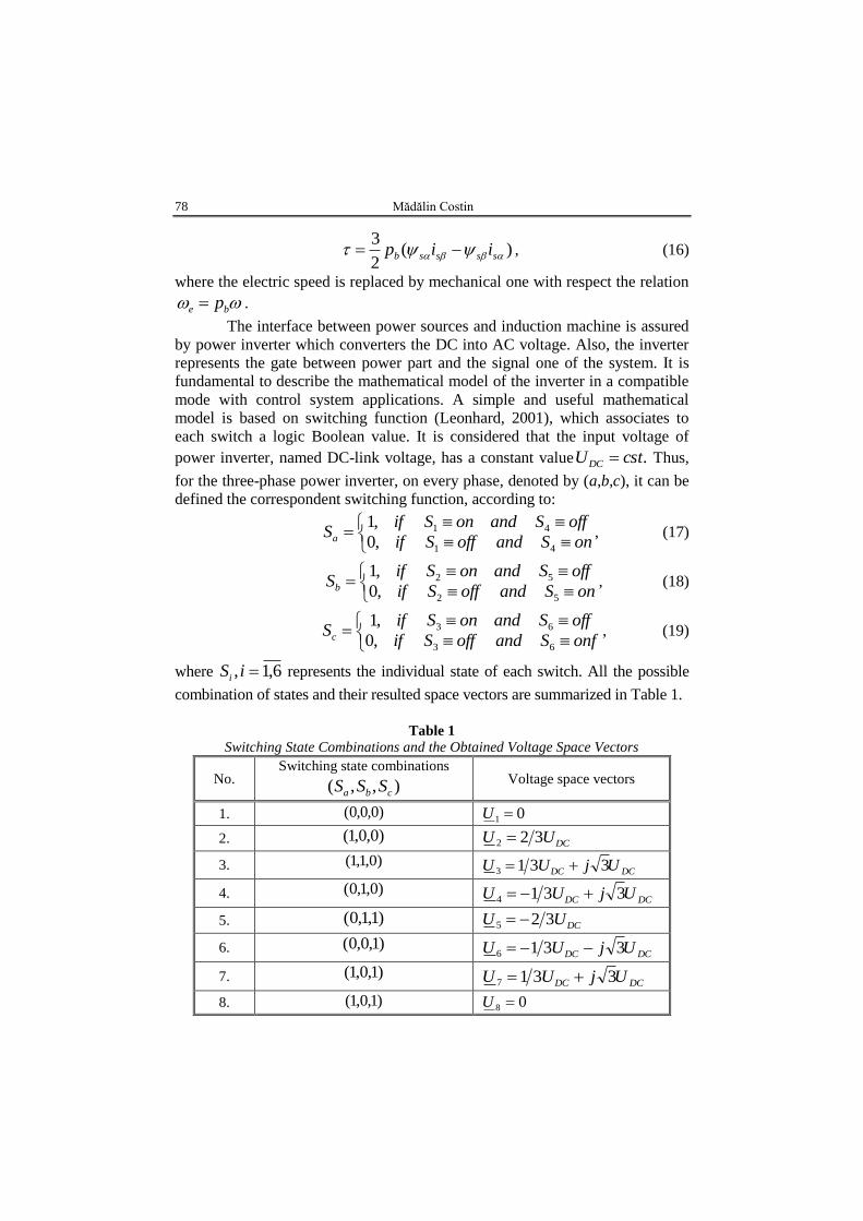
for the three-phase power inverter, on every phase, denoted by (a,b,c), it can be
defined the correspondent switching function, according to:
onSandoffSif
offSandonSifSa
41
41
,0
,1, (17)
onSandoffSif
offSandonSifSb
52
52
,0
,1, (18)
onfSandoffSif
offSandonSifSc
63
63
,0
,1, (19)
where 6,1, iSi represents the individual state of each switch. All the possible
combination of states and their resulted space vectors are summarized in Table 1.
Table 1
Switching State Combinations and the Obtained Voltage Space Vectors
No. Switching state combinations
),,( cba SSS
Voltage space vectors
1. )0,0,0( 01 U
2. )0,0,1( DCUU 322
3. )0,1,1( DCDC UjUU 3313
4. )0,1,0( DCDC UjUU 3314
5. )1,1,0( DCUU 325
6. )1,0,0( DCDC UjUU 3316
7. )1,0,1( DCDC UjUU 3317
8. )1,0,1( 08 U
Bul. Inst. Polit. Iaşi, Vol. 66 (70), Nr. 1, 2020 79
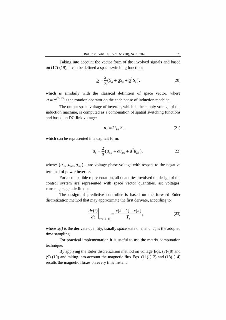
Taking into account the vector form of the involved signals and based
on (17)-(19), it can be defined a space switching function:
)(3
2 2
cba SaSaSS , (20)
which is similarly with the classical definition of space vector, where 3/2jea is the rotation operator on the each phase of induction machine.
The output space voltage of invertor, which is the supply voltage of the
induction machine, is computed as a combination of spatial switching functions
and based on DC-link voltage:
SUu DSs , (21)
which can be represented in a explicit form:
)(3
2 2
cNbNaNs uauauu , (22)
where: ),,( cNbNaN uuu - are voltage phase voltage with respect to the negative
terminal of power inverter.
For a compatible representation, all quantities involved on design of the
control system are represented with space vector quantities, as: voltages,
currents, magnetic flux etc.
The design of predictive controller is based on the forward Euler
discretization method that may approximate the first derivate, according to:
ekxx T
kxkx
dt
tdx ][]1[)(
]1[
, (23)
where x(t) is the derivate quantity, usually space state one, and Te is the adopted
time sampling.
For practical implementation it is useful to use the matrix computation
technique.
By applying the Euler discretization method on voltage Eqs. (7)-(8) and
(9)-(10) and taking into account the magnetic flux Eqs. (11)-(12) and (13)-(14)
results the magnetic fluxes on every time instant
80 Mădălin Costin
)(
)(
)(
)(
)1(ˆ)1(ˆ
)(ˆ)(ˆ
ki
kiTR
ku
kuT
k
k
k
k
s
ses
s
se
s
s
s
s
, (24)
m
rsm
s
s
s
s
m
r
r
r
L
LLL
ki
ki
k
k
L
L
k
k
)(
)(
)1(ˆ)1(ˆ
)(ˆ)(ˆ
. (25)
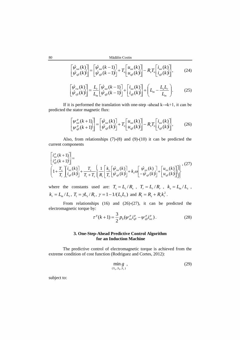
If it is performed the translation with one-step -ahead k→k+1, it can be
predicted the stator magnetic flux:
)(
)(
)(
)(
)(ˆ)(ˆ
)1(
)1(
ki
kiTR
ku
kuT
k
k
k
k
s
ses
s
se
s
sp
s
p
s
, (26)
Also, from relationships (7)-(8) and (9)-(10) it can be predicted the
current components
)(
)(
)(ˆ)(ˆ
)(ˆ)(ˆ1
)(
)(1
)1(
)1(
ku
ku
k
kk
k
k
T
k
RTT
T
ki
ki
T
T
ki
ki
s
s
s
sr
s
s
r
r
tst
s
s
s
t
s
p
s
p
s
, (27)
where the constants used are: sss RLT / , rrr RLT / , sms LLk / ,
rmr LLk / , tst RLT / , )/(11 rsLL and 2
rrst kRRR .
From relationships (16) and (26)-(27), it can be predicted the
electromagnetic torque by:
)(2
3)1( p
s
p
s
p
s
p
sb
p iipk . (28)
3. One-Step-Ahead Predictive Control Algorithm
for an Induction Machine
The predictive control of electromagnetic torque is achieved from the
extreme condition of cost function (Rodriguez and Cortes, 2012):
),,(
mincba SSS
g , (29)
subject to:
Bul. Inst. Polit. Iaşi, Vol. 66 (70), Nr. 1, 2020 81
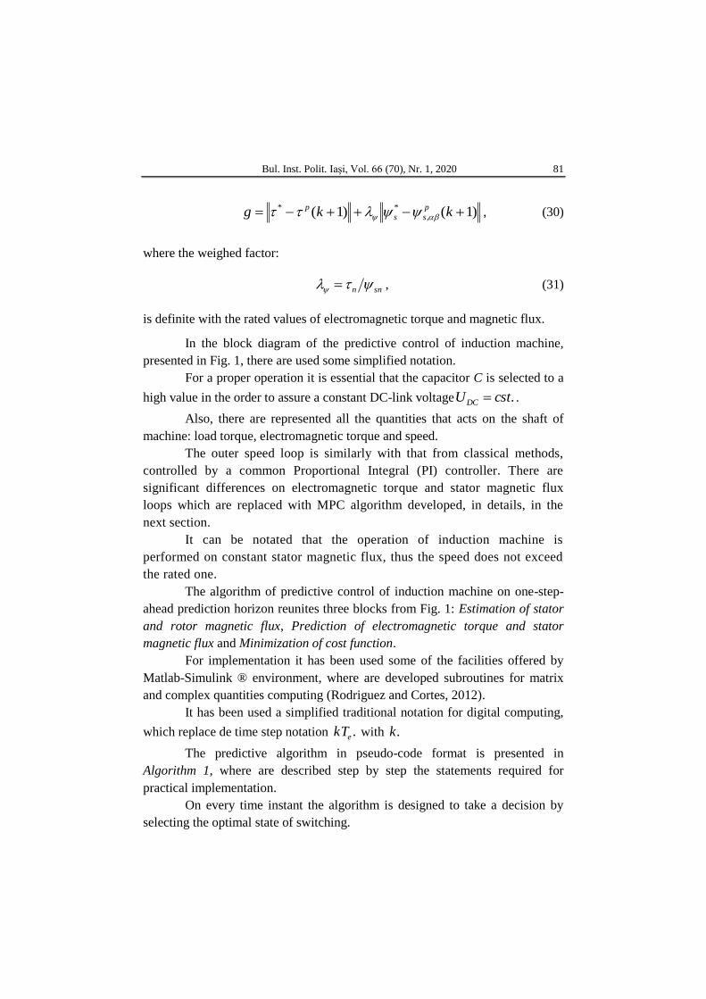
)1()1( ,
** kkg p
ss
p
, (30)
where the weighed factor:
snn , (31)
is definite with the rated values of electromagnetic torque and magnetic flux.
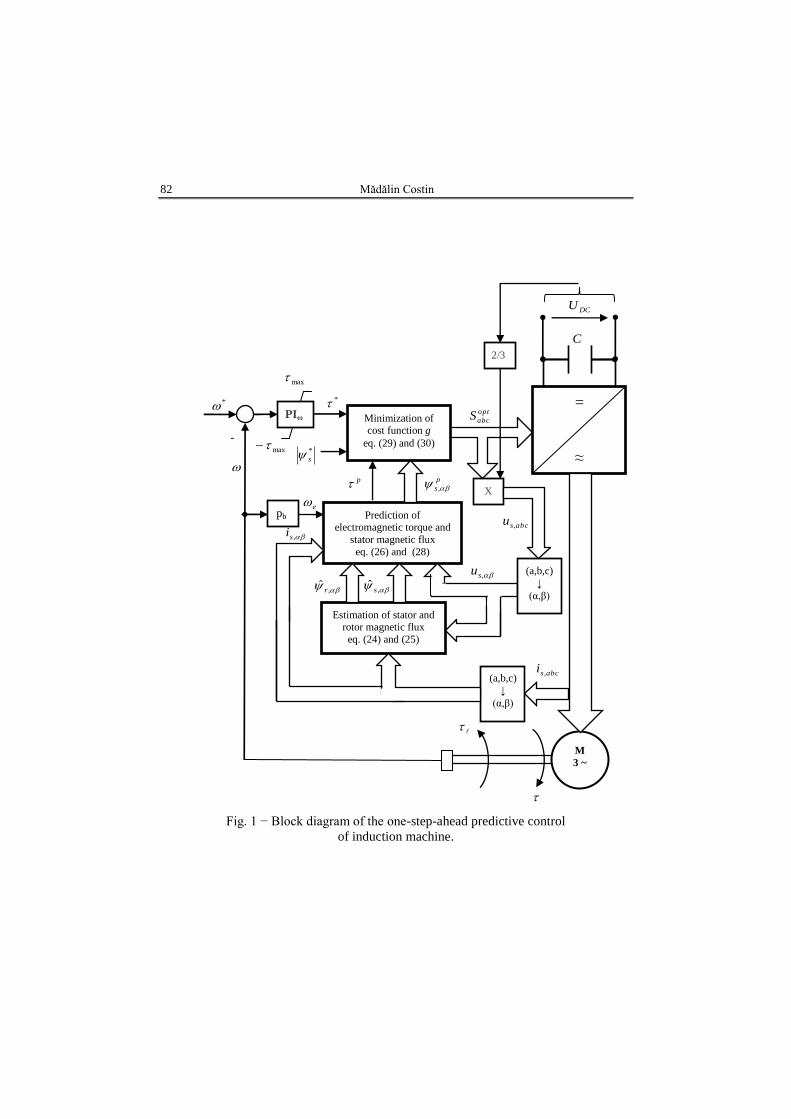
In the block diagram of the predictive control of induction machine,
presented in Fig. 1, there are used some simplified notation.
For a proper operation it is essential that the capacitor C is selected to a
high value in the order to assure a constant DC-link voltage .cstUDC .
Also, there are represented all the quantities that acts on the shaft of
machine: load torque, electromagnetic torque and speed.
The outer speed loop is similarly with that from classical methods,
controlled by a common Proportional Integral (PI) controller. There are
significant differences on electromagnetic torque and stator magnetic flux
loops which are replaced with MPC algorithm developed, in details, in the
next section.
It can be notated that the operation of induction machine is
performed on constant stator magnetic flux, thus the speed does not exceed
the rated one.
The algorithm of predictive control of induction machine on one-step-
ahead prediction horizon reunites three blocks from Fig. 1: Estimation of stator
and rotor magnetic flux, Prediction of electromagnetic torque and stator
magnetic flux and Minimization of cost function.
For implementation it has been used some of the facilities offered by
Matlab-Simulink ® environment, where are developed subroutines for matrix
and complex quantities computing (Rodriguez and Cortes, 2012).
It has been used a simplified traditional notation for digital computing,
which replace de time step notation .ekT with .k
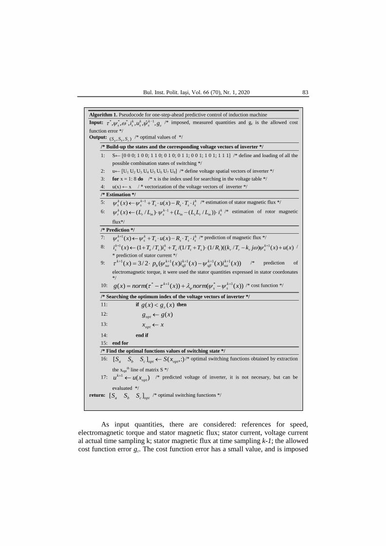
The predictive algorithm in pseudo-code format is presented in
Algorithm 1, where are described step by step the statements required for
practical implementation.
On every time instant the algorithm is designed to take a decision by
selecting the optimal state of switching.
82 Mădălin Costin
Fig. 1 − Block diagram of the one-step-ahead predictive control
of induction machine.
=
≈
Minimization of cost function g
eq. (29) and (30)
PIω
M
3 ~
Prediction of electromagnetic torque and
stator magnetic flux
eq. (26) and (28)
pb
*
-
2/3
X
Estimation of stator and rotor magnetic flux
eq. (24) and (25)
(a,b,c)
↓
(α,β)
(a,b,c)
↓
(α,β)
max
max
*
s
p
s ,
*
p
,ˆ
r
,ˆ
s
DCU
e
opt
abcS
abcsu ,
,su
,si
C
abcsi ,
Bul. Inst. Polit. Iaşi, Vol. 66 (70), Nr. 1, 2020 83
As input quantities, there are considered: references for speed,
electromagnetic torque and stator magnetic flux; stator current, voltage current
al actual time sampling k; stator magnetic flux at time sampling k-1; the allowed
cost function error gε. The cost function error has a small value, and is imposed
Algorithm 1. Pseudocode for one-step-ahead predictive control of induction machine
Input: gui k
s
k
s
k
ss ,ˆ,,,,, 1*** /* imposed, measured quantities and gε is the allowed cost
function error */
Output: ),,( cba SSS /* optimal values of */
/* Build-up the states and the corresponding voltage vectors of inverter */
1: S← [0 0 0; 1 0 0; 1 1 0; 0 1 0; 0 1 1; 0 0 1; 1 0 1; 1 1 1] /* define and loading of all the
possible combination states of switching */
2: u← [U1 U2 U3 U4 U5 U6 U7 U8] /* define voltage spatial vectors of inverter */
3: for x = 1: 8 do /* x is the index used for searching in the voltage table */
4: u(x) ← x / * vectorization of the voltage vectors of inverter */
/* Estimation */
5: k
ssss
k
s
k
s iTRxuTx )()( 1 /* estimation of stator magnetic flux */
6: k
smrsm
k
smr
k
r iLLLLLLx ))/(()/()( 1 /* estimation of rotor magnetic
flux*/
/* Prediction */
7: k
ssss
k
s
k
s iTRxuTx )()(1 /* prediction of magnetic flux */
8: )()()/)((/1()/1/()/1()( 11 xuxjkTkRTTTiTTxi k
srrrtste
k
sse
k
s /
* prediction of stator current */
9: ))()()()((2/3)( 11111 xixxixpx k
s
k
s
k
s
k
sb
k /* prediction of
electromagnetic torque, it were used the stator quantities expressed in stator coordonates */
10: ))(())(()( 1*1* xnormxnormxg k
ss
k /* cost function */
/* Searching the optimum index of the voltage vectors of inverter */
11: if )()( xgxg then
12: )(xggopt
13: xxopt
14: end if
15: end for
/* Find the optimal functions values of switching state */
16: :),(][ optoptcba xSSSS /* optimal switching functions obtained by extraction
the xoptth line of matrix S */
17: )(1
opt
k xuu /* predicted voltage of inverter, it is not necesary, but can be
evaluated */
return: optcba SSS ][ /* optimal switching functions */
84 Mădălin Costin
due to the fact that in practice the output voltage of inverter is based on discrete
values of switching, which leads to some small differences besides the
continuous computing.
Further, it is searched the index which leads to optimization problem.
This index is crucial for searching the optimal functions values of switching
which are outputs of the algorithm.
This process of searching the optimal switching state is applied on
every time sampling, therefore it is powerful dependent of the value of time
instant.
4. Numerical Simulations
In the order to check the theoretical background and the algorithm
presented in the previous sections, in this section it is performed a case study of
numerical simulation of one-step-ahead predictive control technique of an
induction machine in Matlab-Simulink environment.
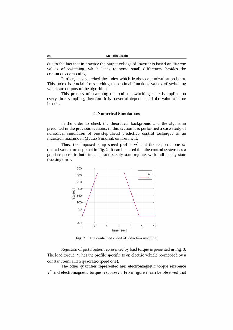
Thus, the imposed ramp speed profile * and the response one
(actual value) are depicted in Fig. 2. It can be noted that the control system has a
good response in both transient and steady-state regime, with null steady-state
tracking error.
Fig. 2 − The controlled speed of induction machine.
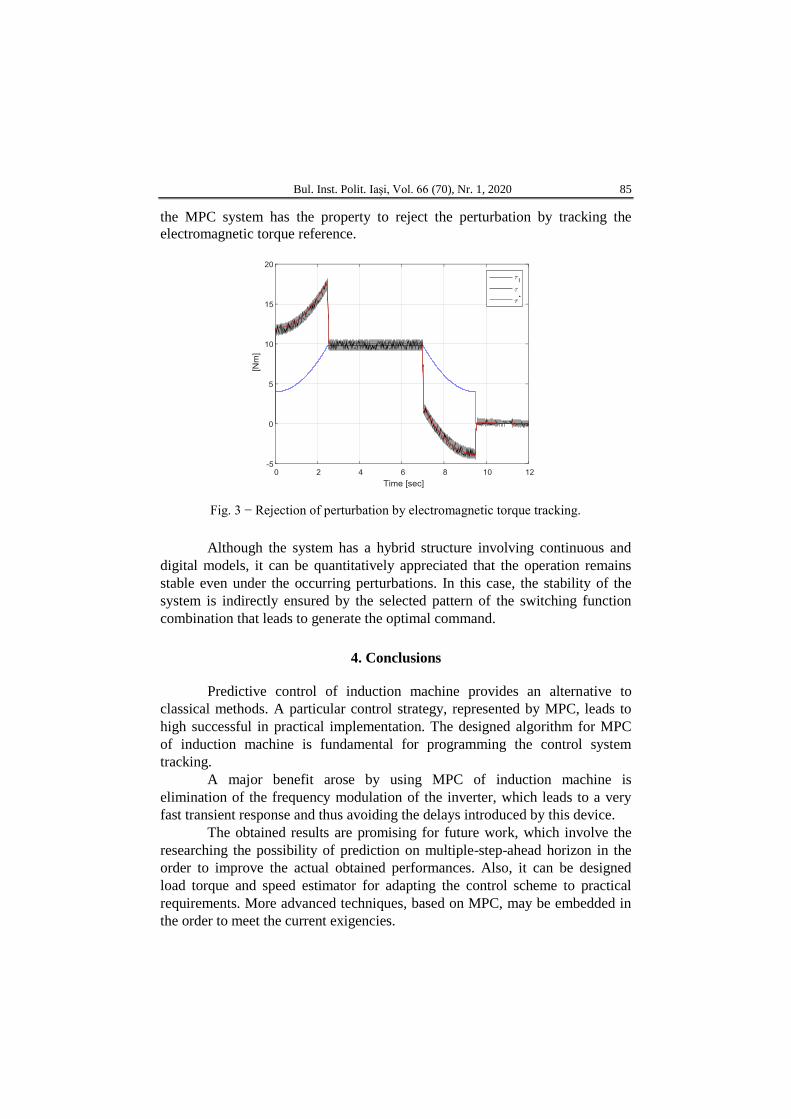
Rejection of perturbation represented by load torque is presented in Fig. 3.
The load torque has the profile specific to an electric vehicle (composed by a
constant term and a quadratic-speed one).
The other quantities represented are: electromagnetic torque reference * and electromagnetic torque response . From figure it can be observed that
Bul. Inst. Polit. Iaşi, Vol. 66 (70), Nr. 1, 2020 85
the MPC system has the property to reject the perturbation by tracking the
electromagnetic torque reference.
Fig. 3 − Rejection of perturbation by electromagnetic torque tracking.
Although the system has a hybrid structure involving continuous and
digital models, it can be quantitatively appreciated that the operation remains
stable even under the occurring perturbations. In this case, the stability of the
system is indirectly ensured by the selected pattern of the switching function
combination that leads to generate the optimal command.
4. Conclusions
Predictive control of induction machine provides an alternative to
classical methods. A particular control strategy, represented by MPC, leads to
high successful in practical implementation. The designed algorithm for MPC
of induction machine is fundamental for programming the control system
tracking.
A major benefit arose by using MPC of induction machine is
elimination of the frequency modulation of the inverter, which leads to a very
fast transient response and thus avoiding the delays introduced by this device.
The obtained results are promising for future work, which involve the
researching the possibility of prediction on multiple-step-ahead horizon in the
order to improve the actual obtained performances. Also, it can be designed
load torque and speed estimator for adapting the control scheme to practical
requirements. More advanced techniques, based on MPC, may be embedded in
the order to meet the current exigencies.
86 Mădălin Costin
REFERENCES
Blaschke F., The Principle of Field Orientation as Applied to the New Transvector
Closed Loop Control System for Rotating Field Machines, Siemens Rev., 34,
217-220, 1972.
Boldea I., Nasar S.A., The Induction Machine Design Handbook, Second Edition, CRC
Press Publishing House, 2009.
Boldea I., Nasar S.A., Electric Drives, Second Edition, CRC Press Publishing House,
2005.
Camacho E.F., Bordons C., Model Predictive Control, Springer Verlag Publishing
House, 2004.
Depenbrock M., Direct Self-Control of the Flux and Rotary Moment of a Rotary-Field
Machine, Patent US4678248, 1984.
Geyer T., Low Complexity Model Predictive Control in Power Electronics and Power
Systems, PhD Thesis, 2005.
Haitham A.R., Iqbal A., Guzinski J., High Performance Control of AC Drives with
MATLAB/Simulink Models, John Wiley and Sons Publishing House, 2012.
Hasse K., On The Dynamics of Speed Control of Static AC Drives with Squirrel-Cage
Induction Machines, Ph.D. dissertation, TH Darmstadt, 1969.
Kennel R., Linder A., Predictive Control of Inverter Supplied Electrical Drives, Proc.
of the IEEE Power Electronics Specialists, Galway, Ireland, 2, 761-766, 2000.
Kennel R., Linder A., Linke M., Generalized Predictive Control (GPC) – Ready for Use
in Drive Applications?, 32nd IEEE Power Electronics Specialists, 4:1839-
1844, 4, Vancouver, 2001.
Kerkman R.J., Twenty Zears of PWM AC Drives: When Secondary Issues Become
Primary Concerns, IEEE IECON Conf. Proc. (1996).
Ku Y.H., Shen D.W.C., Two-Reaction Theory of a General Induction Machine and its
Equivalent Circuit, IEEE Trans. on Power Apparatus and Systems, 76, 3, 729-
734, 1957.
Leonhard W., Control of Electrical Drives, Springer Verlag Publishing House, 2001.
Maciejowski J.M., Predictive Control with Constraints, Prentice Hall Publishing House,
2002.
Matsuo T., Lipo T.A., A Rotor Parameter Identification Scheme for Vector - Controlled
Induction Motor Drives, IEEE Trans. of Industrial Applications, IA-21, 3, 624-
632, 1985.
Park H.R., Two - Reaction Theory of Synchronous Machines Generalized Method of
Analysis - Part I, IEEE Trans. of the American IEEE, 48, 3, 716-717, 1929.
Park H.R., Two - Reaction Theory of Synchronous Machines Generalized Method of
Analysis - Part II, IEEE Trans. of the American IEEE, 52, 2, 352-354, 1933.
Quang N.P., Dittrich J.A., Vector Control of Three-Phase AC Machines - System
Development in the Practice, Springer Publishing House, 2008.
Rawlings J.B., Mayne D.Q., Model Predictive Control: Theory and Design, NobHill
Publishing House, 2009.
Rodriguez J., Cortes P., Predictive Control of Power Converters and Electrical Drives,
Wiley Publishing House, 2012.
Rossiter J.A, Model-Based Predictive Control: A Practical Approach, CRC Press
Publishing House, 2013.
Bul. Inst. Polit. Iaşi, Vol. 66 (70), Nr. 1, 2020 87
Tibamoso K.A., Oñate N.A., Model Predictive Control on Induction Machine for
Electric Traction, Proc. of the CHILEAN Conference on Electrical, Electronics
Engineering, Information and Communication Technologies (CHILECON),
Pucon, 1-5, 2017.
Vas P., Sensorless Vector and Direct Torque Control, Oxford University Press
Publishing House, 1998.
Wróbel K., Serkies, P., Szabat K, Model Predictive Base Direct Speed Control of
Induction Motor Drive-Continuous and Finite Set Approaches, Energie, 13, 5,
1193, 2020.
PARTICULARITĂŢI DE IMPLEMENTARE NUMERICĂ A CONTROLULUI
PREDICTIV PE UN PAS LA MAŞINA ASINCRONĂ
(Rezumat)
În această lucrare este prezentat algoritmul de control predictiv pe un orizont
de un pas în format pseudo-cod pentru reglarea vitezei mașinii asincrone. Îndeplinirea
acestui obiectiv se realizează pe baza modelului ortogonal al mașinii asincrone
reprezentat într-un sistem fix de coordonate statorice. Reglarea predictivă a maşinii
asincrone este o problemă de optimizare a funcției de cost, care conduce la găsirea
funcțiilor optime de comutaţie ale invertorului de putere. Cuplul electromagnetic și
fluxul statoric magnetic sunt reglate de un regulator predictive, care permite urmărirea
referințelor impuse. Rezultatele obținute prin simulare în mediul Matlab-Simulink® ale
cuplului și vitezei confirmă performanțele de control impuse. Se concluzionează că
datorită performanțelor obținute, regulatoarele predictive reprezintă o alternativă la cele
clasice în vederea conducerii mașinii de inducție. Dezvoltarea algoritmilor de reglare
predictivă în acționările electrice cu mașină asincronă, reprezintă o abordarea modernă
ce permite integrarea și implementarea strategiilor avansate de reglare.