Embed Size (px)
Citation preview

IA # OIF-HBPMQ-TX-01.0
IA for HB Integrated PMQ Modulators
Implementation Agreement for
High Bandwidth Integrated Polarization Multiplexed Quadrature Modulators
IA # OIF-HBPMQ-TX-01.0
January 19th, 2017
Implementation Agreement created and approved by the Optical Internetworking Forum
www.oiforum.com

IA # OIF-HBPMQ-TX-01.0
IA for HB Integrated PMQ Modulators
www.oiforum.com 2
The OIF is an international non-profit organization with over 100 member companies, including the world’s leading carriers and vendors. Being an industry group uniting representatives of the data and optical worlds, OIF’s purpose is to accelerate the deployment of interoperable, cost-effective and robust optical internetworks and their associated technologies. Optical internetworks are data networks composed of routers and data switches interconnected by optical networking elements.
With the goal of promoting worldwide compatibility of optical internetworking products, the OIF actively supports and extends the work of national and international standards bodies. Working relationships or formal liaisons have been established with CFP-MSA, COBO, EA, ETSI NFV, IEEE 802.3, IETF, INCITS T11, ITU SG-15, MEF, ONF.
For additional information contact: The Optical Internetworking Forum 5177 Brandin Ct, Fremont, CA 94538
510-492-4040, [email protected]
www.oiforum.com

IA # OIF-HBPMQ-TX-01.0
IA for HB Integrated PMQ Modulators
www.oiforum.com 3
Working Group: Physical and Link Layer (PLL) Working Group
TITLE: Implementation Agreement for High Bandwidth Integrated Polarization Multiplexed Quadrature Modulators
SOURCE: TECHNICAL EDITOR PPL WORKING GROUP CHAIR
Roberto Galeotti David R. Stauffer, Ph.D. Oclaro, Inc. Kandou Bus, SA Via Federico Fellini 4 QI-I 20097 San Donato M.se, Italy 1015 Lausanne, Switzerland Phone: +39 02 51884 216 Phone: +1.802.316.0808 Email: [email protected] Email: [email protected]
PLL WORKING GROUP - OPTICAL VICE CHAIR
Karl Gass Qorvo, Inc. Phone: +1.505.301.1511 Email: [email protected]
ABSTRACT: This Implementation Agreement specifies key aspects of integrated polarization
multiplexed quadrature modulators operating at rates up to 64GBd.

IA # OIF-HBPMQ-TX-01.0
IA for HB Integrated PMQ Modulators
www.oiforum.com 4
Notice: This Technical Document has been created by the Optical Internetworking Forum (OIF). This document is
offered to the OIF Membership solely as a basis for agreement and is not a binding proposal on the companies listed as resources above. The OIF reserves the rights to at any time to add, amend, or withdraw statements contained herein. Nothing in this document is in any way binding on the OIF or any of its members.
The user's attention is called to the possibility that implementation of the OIF implementation agreement contained herein may require the use of inventions covered by the patent rights held by third parties. By publication of this OIF implementation agreement, the OIF makes no representation or warranty whatsoever, whether expressed or implied, that implementation of the specification will not infringe any third party rights, nor does the OIF make any representation or warranty whatsoever, whether expressed or implied, with respect to any claim that has been or may be asserted by any third party, the validity of any patent rights related to any such claim, or the extent to which a license to use any such rights may or may not be available or the terms hereof.
© 2017 Optical Internetworking Forum
This document and translations of it may be copied and furnished to others, and derivative works that comment on or otherwise explain it or assist in its implementation may be prepared, copied, published and distributed, in whole or in part, without restriction other than the following, (1) the above copyright notice and this paragraph must be included on all such copies and derivative works, and (2) this document itself may not be modified in any way, such as by removing the copyright notice or references to the OIF, except as needed for the purpose of developing OIF Implementation Agreements. By downloading, copying, or using this document in any manner, the user consents to the terms and conditions of this notice. Unless the terms and conditions of this notice are breached by the user, the limited permissions granted above are perpetual and will not be revoked by the OIF or its successors or assigns.
This document and the information contained herein is provided on an “AS IS” basis and THE OIF DISCLAIMS ALL WARRANTIES, EXPRESS OR IMPLIED, INCLUDING BUT NOT LIMITED TO ANY WARRANTY THAT THE USE OF THE INFORMATION HEREIN WILL NOT INFRINGE ANY RIGHTS OR ANY IMPLIED WARRANTIES OF MERCHANTABILITY, TITLE OR FITNESS FOR A PARTICULAR PURPOSE.

IA # OIF-HBPMQ-TX-01.0
IA for HB Integrated PMQ Modulators
www.oiforum.com 5
Table of Contents
TABLE OF CONTENTS ....................................................................................... 5
LIST OF FIGURES ............................................................................................... 6
LIST OF TABLES ................................................................................................. 6
1 Document Revision History ........................................................................ 6 2 Introduction ................................................................................................. 7
3 Functionality ............................................................................................... 7 4 Mechanical Properties .............................................................................. 10
5 Electrical Interfaces .................................................................................. 12 5.1 Mechanical Specification and Location of Electrical Interfaces ............ 12 5.2 Electrical Interface Pin Assignments .................................................... 14 5.3 Power Monitor Interface Electrical Properties ...................................... 15
6 Opto-Electronic Properties ....................................................................... 16 7 Optical properties ..................................................................................... 17 8 Environmental .......................................................................................... 17
9 Glossary ................................................................................................... 18 10 List of companies belonging to OIF at document approval date ............... 19

IA # OIF-HBPMQ-TX-01.0
IA for HB Integrated PMQ Modulators
www.oiforum.com 6
List of Figures
FIGURE 1: FUNCTIONAL DIAGRAM OF A POLARIZATION MULTIPLEXED QUADRATURE MODULATED INTEGRATED TRANSMITTER WITH
A DETAILED FUNCTIONAL DIAGRAM OF THE DATA MODULATOR. ............................................................................ 7 FIGURE 2: I AND Q PHASE DEFINITIONS ..................................................................................................................... 9 FIGURE 3: MECHANICAL LAYOUT, ELECTRICAL INTERFACES AND MOUNTING HOLES LOCATION. ........................................... 10 FIGURE 4: G3PO COMPATIBLE CONNECTORS POSITION DETAILS .................................................................................. 11 FIGURE 5: POSITION DETAIL OF G3PO COMPATIBLE CONNECTORS INTERNAL REFERENCE PLANE ......................................... 11 FIGURE 6: STRAIGHT LOW SPEED PINS SPECIFICATION ................................................................................................ 12 FIGURE 7: PCB LANDING PADS SPECIFICATION FOR BENT LOW SPEED PINS ..................................................................... 13 FIGURE 8: FLAT BOTTOM PART HEIGHT SPECIFICATION FOR BENT LOW SPEED PINS ........................................................... 13
List of Tables
TABLE 1: DOCUMENT REVISION HISTORY ................................................................................................................... 6 TABLE 2: ELECTRICAL INTERFACE PIN-OUT AND FUNCTION WITH MULTIPLE OPTIONS FOR BIASING AND PHASE CONTROL .......... 14 TABLE 3: POWER MONITOR INTERFACE ELECTRICAL PROPERTIES ................................................................................... 15 TABLE 4: ELECTRICAL AND OPTO-ELECTRONIC PROPERTIES .......................................................................................... 16 TABLE 5: OPTICAL PROPERTIES .............................................................................................................................. 17 TABLE 6: GLOSSARY ............................................................................................................................................ 18
1 Document Revision History
Table 1 provides the document revision history.
Document Date Revisions/Comments
OIF-HBPMQ-TX-01.0 Jan 19th 2017 Release created from OIF2016.012.05
Table 1: Document revision history

IA # OIF-HBPMQ-TX-01.0
IA for HB Integrated PMQ Modulators
www.oiforum.com 7
2 Introduction
This document details an Implementation Agreement (IA) of an optical integrated Polarization Multiplexed (PM) quadrature modulator for coherent applications with nominal symbol rates up to 64GBaud. This Implementation Agreement strives to remain modulation format and data rate agnostic whenever practical to maximize applicability across applications.
3 Functionality
This Implementation Agreement specifies in detail a single opto-electronic module with the functionality contained in the yellow area enclosed by the bold line in Figure 1. This module will be referred to as Polarization Multiplexed-Quadrature Modulator or PM-Q Modulator.
Figure 1: Functional diagram of a polarization multiplexed quadrature modulated integrated transmitter with a detailed functional diagram of the data modulator.
The optical power from an input fiber is divided into two parts and each part is independently modulated by a quadrature modulator. The resulting two modulated signals are combined with their polarizations orthogonal to each other, and output through an optical output fiber. The power in each of the two polarizations is independently monitored with photodiodes.

IA # OIF-HBPMQ-TX-01.0
IA for HB Integrated PMQ Modulators
www.oiforum.com 8
Each quadrature modulator typically comprises of two inner nested Mach-Zehnder modulators with bias control, a 90º phase shifter in the outer modulator with phase control, and an output power monitoring output. Any implementation or technology choices may be used to realize this basic functionality.
As indicated in Figure 1, the PM-Q Modulator includes the following basic functional components:
One optical input
One optical power splitter
Two independent quadrature modulators
Two independent monitoring photodiodes
One polarization multiplexer
One optical output
The PM-Q Modulator module specified in this Implementation Agreement does not include drivers or any control electronics.
The following independent interfaces are specified for the PM-Q modulator:
One optical input fiber
One optical output fiber
Four high-speed data interfaces
Four modulator bias control interfaces
Two phase control interfaces
Two power monitoring interfaces
The two polarized signal components in the output are referred to as “X” and “Y”, and the quadrature modulators that encode information onto the polarization components are correspondingly referred to as X and Y modulators. Each quadrature modulator is driven by an “I” and a “Q” data signal. The four high-speed data interfaces are referred to as XI, XQ, YI and YQ.
Each of the four data modulators needs to be biased with a suitable DC voltage. This IA specifies biasing pins supporting both single-ended as well as push-pull biasing. The naming of the bias pins is consistent with the naming of the high-speed data interfaces. The I and Q phase offset is controlled via phase control pins also supporting both single-ended as well as push-pull control. The phase offset between I and Q in X and Y arms is controlled by phase control interfaces X Phase and Y Phase respectively.

IA # OIF-HBPMQ-TX-01.0
IA for HB Integrated PMQ Modulators
www.oiforum.com 9
I and Q are established by the heterodyne technique, with the frequency of the Signal input to the receiver greater than the frequency of the LO input. The I and Q channel outputs are measured in the time domain.
Under these conditions the Signal Q channel phase lags by nominally +90 degrees the Signal I channel phase, as shown in Figure 2.
Figure 2: I and Q phase definitions

IA # OIF-HBPMQ-TX-01.0
IA for HB Integrated PMQ Modulators
www.oiforum.com 10
4 Mechanical Properties
Dimensions of the mechanical layout are defined in Figure 3; high speed interface position details are defined in Figure 4 and Figure 5 (dimensions are in mm and are intended as nominal values if not otherwise specified). A reference point or datum (D) is used to reference the extent of the module, the location of all electrical interfaces, mounting holes and fiber bending radius.
Figure 3: Mechanical layout, electrical interfaces and mounting holes location.
LL and LR specify maximum dimensions. Lower values than these are allowed.
Boot lengths are not explicitly specified to avoid restricting the choice of implementation or technology.
Mounting holes shall be M2 type threaded.

IA # OIF-HBPMQ-TX-01.0
IA for HB Integrated PMQ Modulators
www.oiforum.com 11
Figure 4: G3PO compatible connectors position details
Figure 5: Position detail of G3PO compatible connectors internal reference plane
Package side wall
Connector simplified structure
Package bottom
IA # OIF-HBPMQ-TX-01.0
IA for HB Integrated PMQ Modulators
www.oiforum.com 12
5 Electrical Interfaces
5.1 Mechanical Specification and Location of Electrical Interfaces
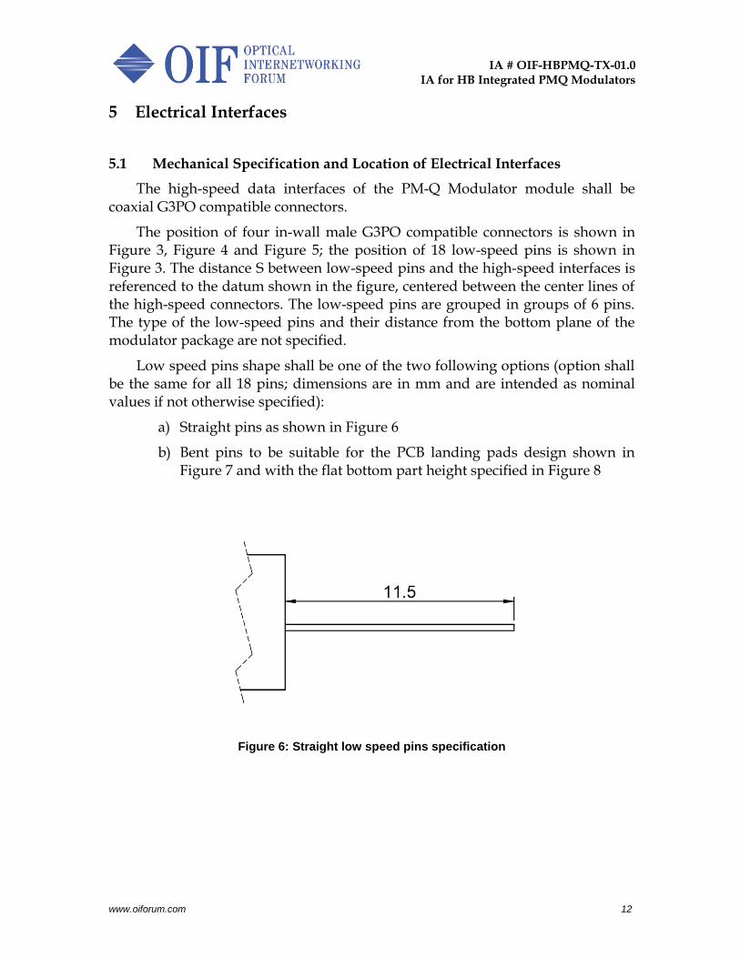
The high-speed data interfaces of the PM-Q Modulator module shall be coaxial G3PO compatible connectors.
The position of four in-wall male G3PO compatible connectors is shown in Figure 3, Figure 4 and Figure 5; the position of 18 low-speed pins is shown in Figure 3. The distance S between low-speed pins and the high-speed interfaces is referenced to the datum shown in the figure, centered between the center lines of the high-speed connectors. The low-speed pins are grouped in groups of 6 pins. The type of the low-speed pins and their distance from the bottom plane of the modulator package are not specified.
Low speed pins shape shall be one of the two following options (option shall be the same for all 18 pins; dimensions are in mm and are intended as nominal values if not otherwise specified):
a) Straight pins as shown in Figure 6
b) Bent pins to be suitable for the PCB landing pads design shown in Figure 7 and with the flat bottom part height specified in Figure 8
Figure 6: Straight low speed pins specification

IA # OIF-HBPMQ-TX-01.0
IA for HB Integrated PMQ Modulators
www.oiforum.com 13
Figure 7: PCB landing pads specification for bent low speed pins
Figure 8: Flat bottom part height specification for bent low speed pins
Mounting holes on package pins side
PCB pad numbers referred to the modulator pins assignments defined in Figure 3 and Table 2

IA # OIF-HBPMQ-TX-01.0
IA for HB Integrated PMQ Modulators
www.oiforum.com 14
5.2 Electrical Interface Pin Assignments
The pin numbering starts with the first high-speed data interface connector furthest from the low-speed pins and the pin number increases towards the opposite side. Electrical interface grouping, ordering and function are listed in Table 2.
Pin Symbol Description
1 Data_XI X-polarization in-phase data input
2 Data_XQ X-polarization quadrature data input
3 Data_YI Y-polarization in-phase data input
4 Data_YQ Y-polarization quadrature data input
5 Bias_YQ(p) Bias_YQ YQ modulator (positive) bias
6 Bias_YQ(n) GND or NC YQ modulator neg. bias (push-pull) or GND or NC (single-ended)
7 Bias_YI(p) Bias_YI YI modulator (positive) bias
8 Bias_YI(n) GND or NC YI modulator neg. bias (push-pull) or GND or NC (single-ended)
9 Bias_XQ(p) Bias_XQ XQ modulator (positive) bias
10 Bias_XQ(n) GND or NC XQ modulator neg. bias (push-pull) or GND or NC (single-ended)
11 Bias_XI(p) Bias_XI XI modulator (positive) bias
12 Bias_XI(n) GND or NC XI modulator neg. bias (push-pull) or GND or NC (single-ended)
13 Phase_Y(p) Phase_Y Y pol. phase (positive)
14 Phase_Y(n) GND or NC Y pol. phase negative (push-pull) or GND or NC (single-ended)
15 Phase_X(p) Phase_X X pol. phase (positive)
16 Phase_X(n) GND or NC X pol. phase negative (push-pull) or GND or NC (single-ended)
17 NC Not Connected
18 Y_A Y-polarization photodiode Anode
19 Y_C Y-polarization photodiode Cathode
20 GND Ground
21 X_C X-polarization photodiode Cathode
22 X_A X-polarization photodiode Anode
Table 2: Electrical interface pin-out and function with multiple options for biasing and phase control

IA # OIF-HBPMQ-TX-01.0
IA for HB Integrated PMQ Modulators
www.oiforum.com 15
5.3 Power Monitor Interface Electrical Properties
The electrical properties related to the power monitor diodes are specified in Table 3. The opto-electronic properties of the optical modulator including the high-speed data interfaces are specified in Section 6.
Parameter Unit Min. Typ. Max. Remarks
Monitor PD Responsivity
mA/W 50 800 Referred to output power complementary taps
Monitoring PD E/O Bandwidth
GHz 1
Table 3: Power monitor interface electrical properties

IA # OIF-HBPMQ-TX-01.0
IA for HB Integrated PMQ Modulators
www.oiforum.com 16
6 Opto-Electronic Properties
Electrical specification of the high-speed interface and opto-electronic properties are given in Table 4 at the end of life over the operating temperature and frequency ranges.
Parameter Unit Min. Typ. Max. Remarks
S21 E/O bandwidth @-3dB @-6dB
GHz
35 45
3% smoothed, reference frequency at 2GHz
S11 Electrical Return loss f < 30GHz 30 < f < 45GHz
dB
-10 -8
RF Impedance Ohm 50
Vpi_RF V 3.5 Measured at 2GHz
Vpi_Phase V (*1)
I/Q skew (*2) ps 50 For each polarization component
Total skew (*3) ps 100
I/Q skew variation (*4) ps 1.5
Total skew variation ps 4 *1 - Application specific – covering a range of applications for this component. *2 - I/Q skew is the skew between channel pairs XI and XQ, and YI and YQ. *3 - Total skew is the maximum skew between any of the four physical channels XI, XQ, YI and YQ. *4 - The objective of this specification is to minimize skew variation between I and Q. I/Q skew variation is a key
parameter for system operation in some DSPs
Table 4: Electrical and opto-electronic properties
Skew is defined as the maximum signal propagation time difference between physical signal channels, between electrical input and optical output interfaces. Skew includes any skew variation due to aging, temperature and any other effects.

IA # OIF-HBPMQ-TX-01.0
IA for HB Integrated PMQ Modulators
www.oiforum.com 17
7 Optical properties
Optical properties of the optical modulator are listed in Table 5 at the end of life over the operating temperature and frequency ranges.
Parameter Unit Min. Typ. Max. Remarks
Operating Frequency C-Band L-Band
THz
191.35 186.0
196.2 191.5
At least one range shall be supported in one device
Input power dBm 18 Peak power
Insertion loss dB (*1) 14 All modulators at peak transmission, for each polarization
Insertion loss difference between X and Y
(*1)
Optical return loss dB 30 Input and output
Parent MZI ER dB 22
Child MZI ER Basic Performance Extended Performance
dB
22 25
Polarization ER dB 20
*1 - Application specific – covering a range of applications for this component.
Table 5: Optical properties
The input fiber shall be polarization maintaining (PMF) with a 125µm cladding diameter and a 250µm coating diameter. The PMF shall have a maximum “Minimum Bending Radius” of 7.5mm (as shown in Figure 3).
The output fiber shall be single mode (SMF) with a 125µm cladding diameter and a 250µm coating diameter. The SMF shall be compliant to ITU-T recommendations G.657.B3 and G.652.D, and therefore shall have a maximum “Minimum Bending Radius” of 5mm (as shown in Figure 3).
The PMF color shall be natural (transparent) and the SMF color shall be white.
The optical connector key shall be aligned to the slow axis of the polarization maintaining fiber. Optical and opto-electronic specifications assume that a polarized input signal is launched into the slow axis of the input fiber.
8 Environmental
The typically expected operating temperature range is -5ºC to +75ºC. For the purpose of uniform calculation of the Failures In Time (FIT) rate, a fielded temperature of 55ºC shall be used.

IA # OIF-HBPMQ-TX-01.0
IA for HB Integrated PMQ Modulators
www.oiforum.com 18
9 Glossary
Table 6 presents definitions for acronyms used in this IA.
Term Definition
BS Beam Splitter
DC Direct Current
E/O Electro-Optical
ER Extinction Ratio
FIT Failures In Time
GND Ground
I In Phase
IA Implementation Agreement
LO Local Oscillator
MZI Mach-Zehnder Interferometer
NC Not Connected
PBC Polarization Beam Combiner
PCB Printed Circuit Board
PD Photodiode
PM Polarization Multiplexed
PMF Polarization Maintaining Fiber
PM-Q Polarization Multiplexed Quadrature
Q Quadrature
RF Radio Frequency
SMF Single Mode Fiber
Table 6: Glossary

IA # OIF-HBPMQ-TX-01.0
IA for HB Integrated PMQ Modulators
www.oiforum.com 19
10 List of companies belonging to OIF at document approval date
Acacia Communications GigPeak O-Net Communications (HK) Limited
ADVA Optical Networking Global Foundries Oclaro
Alcatel-Lucent Google Orange
Alibaba (China) Co., Ltd Hitachi PETRA
AMCC Huawei Technologies Co., Ltd.
QLogic Corporation
Amphenol Corp. Infinera Qorvo
Anritsu Inphi Rockley Photonics
Broadcom Limited Intel Samsung Electronics Co. Ltd.
Brocade Ixia Samtec Inc.
BRPhotonics Juniper Networks Semtech
China Telecom Kandou Bus Socionext Inc.
Ciena Corporation KDDI R&D Laboratories Spirent Communications
Cisco Systems Keysight Technologies, Inc. Sumitomo Electric Industries
ClariPhy Communications Lumentum Sumitomo Osaka Cement
Coriant MACOM Technology Solutions
TE Connectivity
CPqD Marvell Technology Tektronix
Credo Semiconductor (HK) LTD
Mellanox Technologies Teledyne LeCroy
Dell, Inc. Microsemi Inc. TELUS Communications, Inc.
ETRI Microsoft Corporation Time Warner Cable
Fiberhome Technologies Group
Mitsubishi Electric Corporation
UNH InterOperability Laboratory (UNH-IOL)
Finisar Corporation Molex Verizon
Foxconn Interconnect Technology, Ltd.
MoSys, Inc. Viavi Solutions Deutschland GmbH
Fujikura MRV Xilinx
Fujitsu NEC Corporation Yamaichi Electronics Ltd.
Furukawa Electric Japan NeoPhotonics ZTE Corporation
Gigamon Inc. NTT Corporation