Embed Size (px)
Citation preview

Implement Effective
Computer System Validation
Noelia Ortiz, MME, CSSGB, CQA
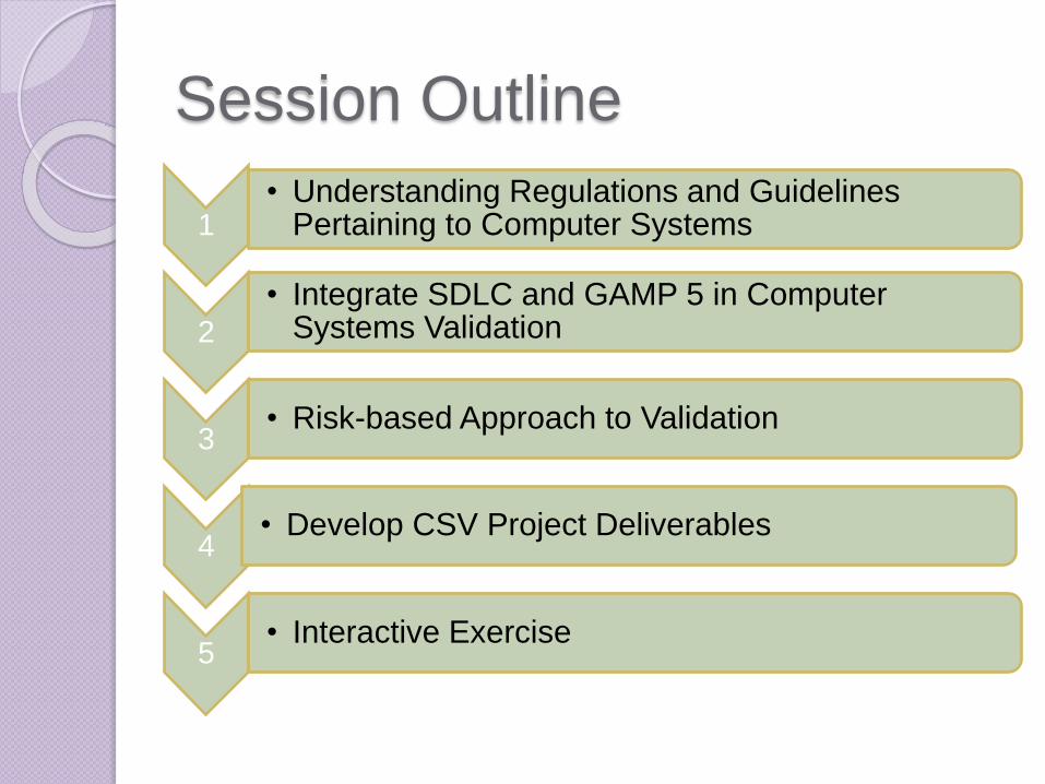
Session Outline
1• Understanding Regulations and Guidelines
Pertaining to Computer Systems
2
• Integrate SDLC and GAMP 5 in Computer Systems Validation
3• Risk-based Approach to Validation
4 • Develop CSV Project Deliverables
5• Interactive Exercise
PART 1: UNDERSTANDING
REGULATIONS AND
GUIDELINES PERTAINING
TO COMPUTER SYSTEMS
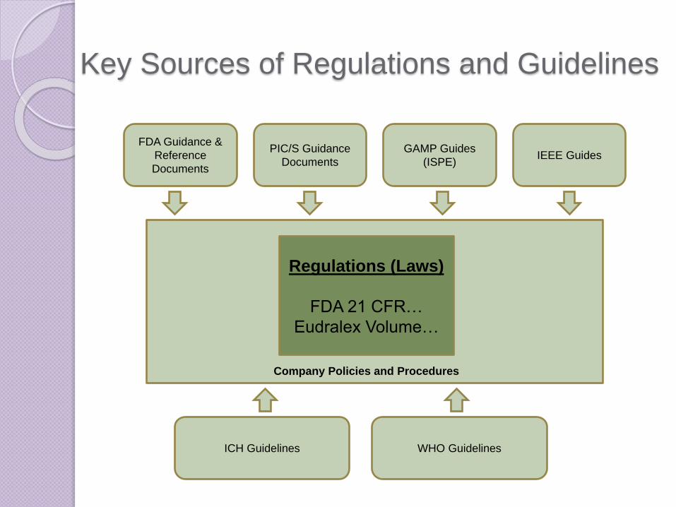
Key Sources of Regulations and Guidelines
FDA Guidance &
Reference
Documents
PIC/S Guidance
Documents
GAMP Guides
(ISPE)IEEE Guides
Regulations (Laws)
FDA 21 CFR…
Eudralex Volume…
ICH Guidelines
Company Policies and Procedures
WHO Guidelines
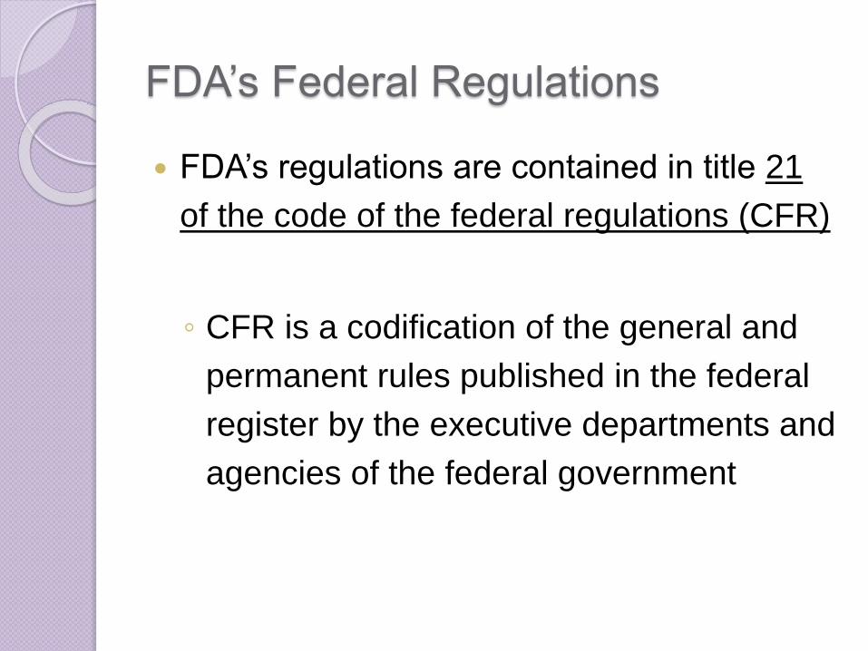
FDA’s Federal Regulations
FDA’s regulations are contained in title 21
of the code of the federal regulations (CFR)
◦ CFR is a codification of the general and
permanent rules published in the federal
register by the executive departments and
agencies of the federal government

FDA’s Federal Regulations
There is no specific regulation that defines
how to perform computer system validation
Very few regulations specifically deal with
computer or automated systems
Terms such as “automated”, “electronic”,
“records”, “data”, and “system” are
indicators of regulations applicable to
computer systems
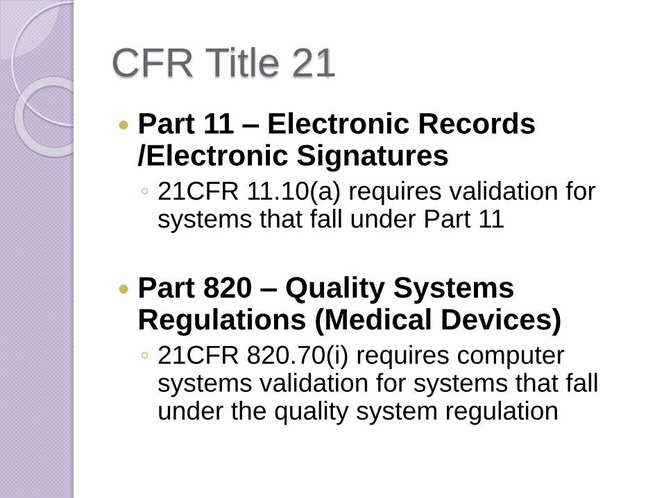
CFR Title 21
Part 11 – Electronic Records /Electronic Signatures◦ 21CFR 11.10(a) requires validation for
systems that fall under Part 11
Part 820 – Quality Systems Regulations (Medical Devices)◦ 21CFR 820.70(i) requires computer
systems validation for systems that fall under the quality system regulation
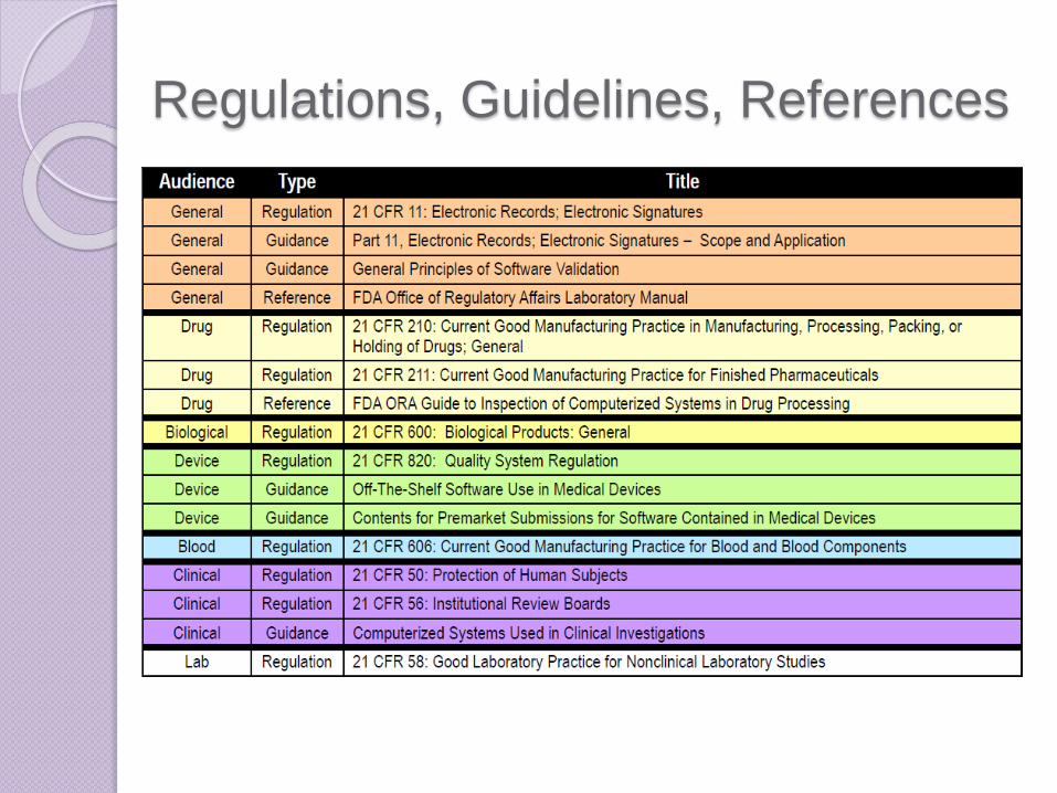
Regulations, Guidelines, References
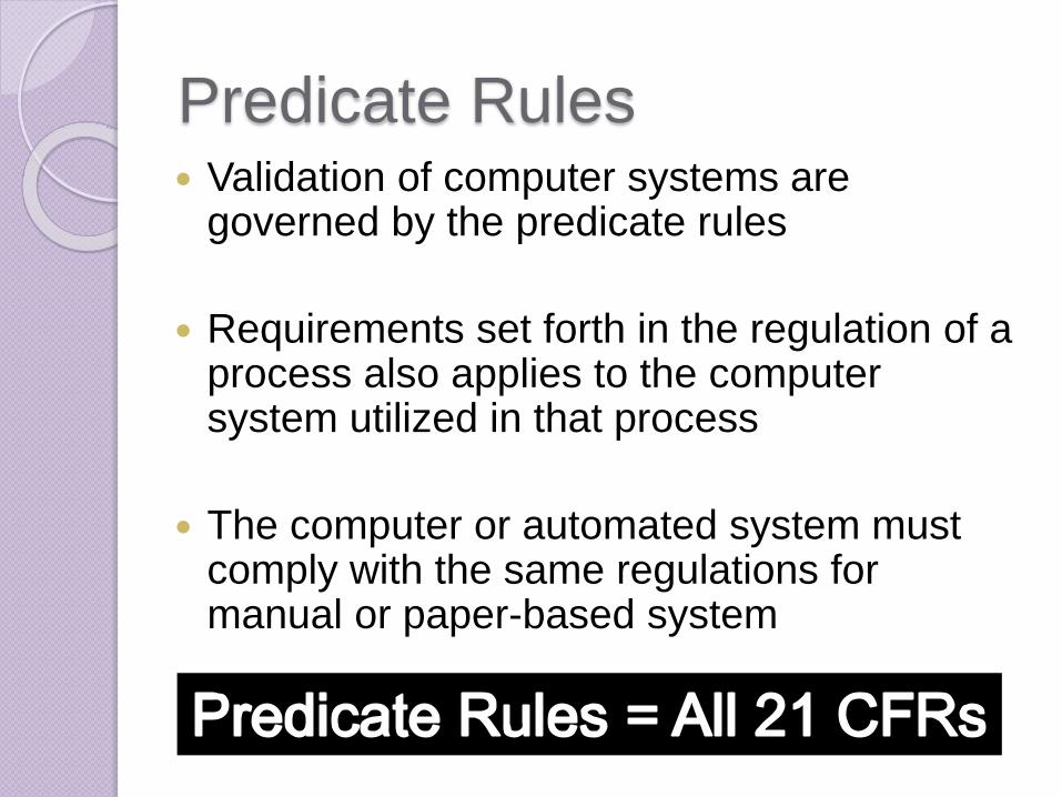
Predicate Rules Validation of computer systems are
governed by the predicate rules
Requirements set forth in the regulation of a process also applies to the computer system utilized in that process
The computer or automated system must comply with the same regulations for manual or paper-based system
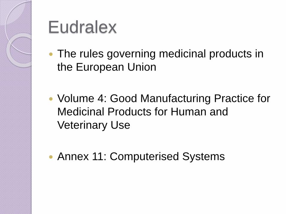
Eudralex
The rules governing medicinal products in
the European Union
Volume 4: Good Manufacturing Practice for
Medicinal Products for Human and
Veterinary Use
Annex 11: Computerised Systems
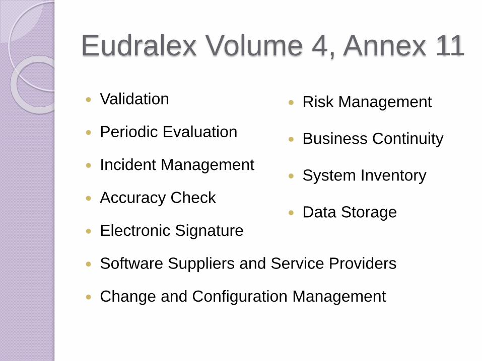
Eudralex Volume 4, Annex 11
Validation
Periodic Evaluation
Incident Management
Accuracy Check
Electronic Signature
Software Suppliers and Service Providers
Change and Configuration Management
Risk Management
Business Continuity
System Inventory
Data Storage
PART 2: INTEGRATE SDLC MODULES AND GAMP 5 IN CSV
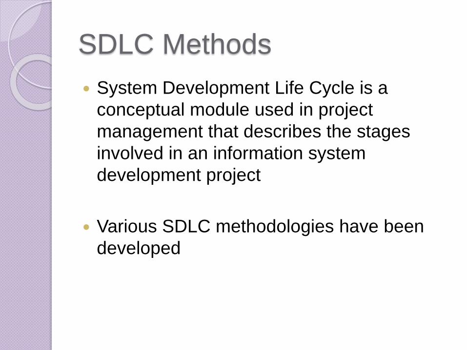
SDLC Methods
System Development Life Cycle is a
conceptual module used in project
management that describes the stages
involved in an information system
development project
Various SDLC methodologies have been
developed
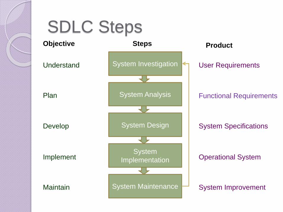
SDLC Steps
System Investigation
System Analysis
Objective Steps Product
System Design
System Maintenance
System
Implementation
Understand
Develop
Implement
Maintain
Plan
User Requirements
Functional Requirements
System Specifications
Operational System
System Improvement
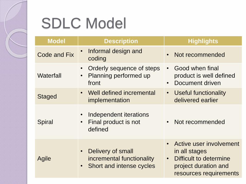
SDLC ModelModel Description Highlights
Code and Fix• Informal design and
coding• Not recommended
Waterfall
• Orderly sequence of steps
• Planning performed up
front
• Good when final
product is well defined
• Document driven
Staged• Well defined incremental
implementation
• Useful functionality
delivered earlier
Spiral
• Independent iterations
• Final product is not
defined
• Not recommended
Agile
• Delivery of small
incremental functionality
• Short and intense cycles
• Active user involvement
in all stages
• Difficult to determine
project duration and
resources requirements
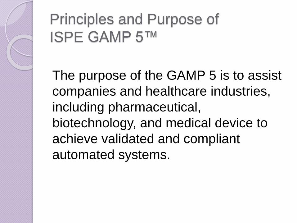
Principles and Purpose of
ISPE GAMP 5™
The purpose of the GAMP 5 is to assist
companies and healthcare industries,
including pharmaceutical,
biotechnology, and medical device to
achieve validated and compliant
automated systems.
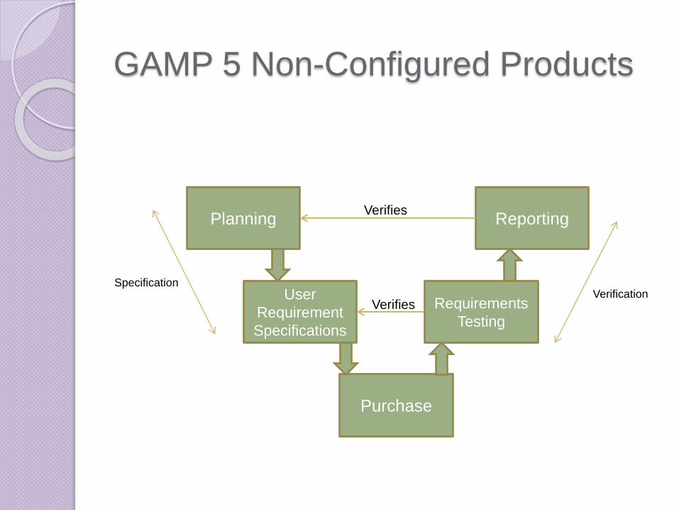
GAMP 5 Non-Configured Products
Planning Reporting
Purchase
Requirements
Testing
User
Requirement
Specifications
Verifies
Verifies
SpecificationVerification
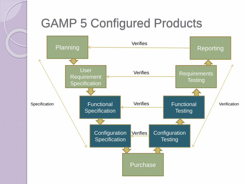
GAMP 5 Configured Products
Planning Reporting
Purchase
Requirements
Testing
User
Requirement
Specification
Verifies
VerifiesSpecification VerificationFunctional
Specification
Configuration
Specification
Functional
Testing
Configuration
Testing
Verifies
Verifies
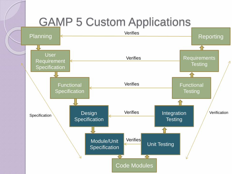
GAMP 5 Custom ApplicationsPlanning Reporting
Code Modules
Requirements
Testing
User
Requirement
Specification
Verifies
Verifies
SpecificationVerification
Functional
Specification
Module/Unit
Specification
Functional
Testing
Unit Testing
Verifies
Verifies
Design
Specification
Integration
Testing
Verifies

PART 3: RISK BASED APPROACH TO VALIDATION
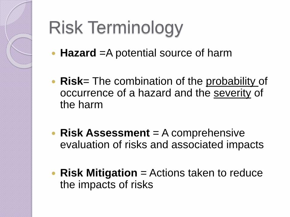
Risk Terminology
Hazard =A potential source of harm
Risk= The combination of the probability of occurrence of a hazard and the severity of the harm
Risk Assessment = A comprehensive evaluation of risks and associated impacts
Risk Mitigation = Actions taken to reduce the impacts of risks

Risk Management Framework
Risk Assessment System Risk Assessment SOP
Risk Mitigation
SOP’s
• Risk Based Validation
• Audit Trails
• System Security
• Software Vendor Assessment
• User Training
• Incident Management
• System Backup
• Alternate Records
• etc.

Risk Assessment
Roles and Responsibilities
Business Process OwnerIdentify, Evaluate and
Classify Risks
Technology Owner
Provide information on
how the software
works and evaluate
failures and impact
Quality Assurance
Evaluate Risks
associated with
Regulatory
Compliance and
Company Policies

When does Risk Assessment take
place?
Planning Reporting
Purchase,
Coding or
Configuration
VerificationSpecification
Preliminary
Risk
Screening
Detailed
Risk
Assessment

Risk Assessment Steps
Identification Evaluation Classification Mitigation
Risk Assessment Activities
Determine
and
document
the hazards
associated
with use of
the system
Determine
the severity
of the
identified
hazards
Categorized
the risks
according to
severity
Perform
activities
that reduce
the severity
of the risk
or the
likelihood of
the risk
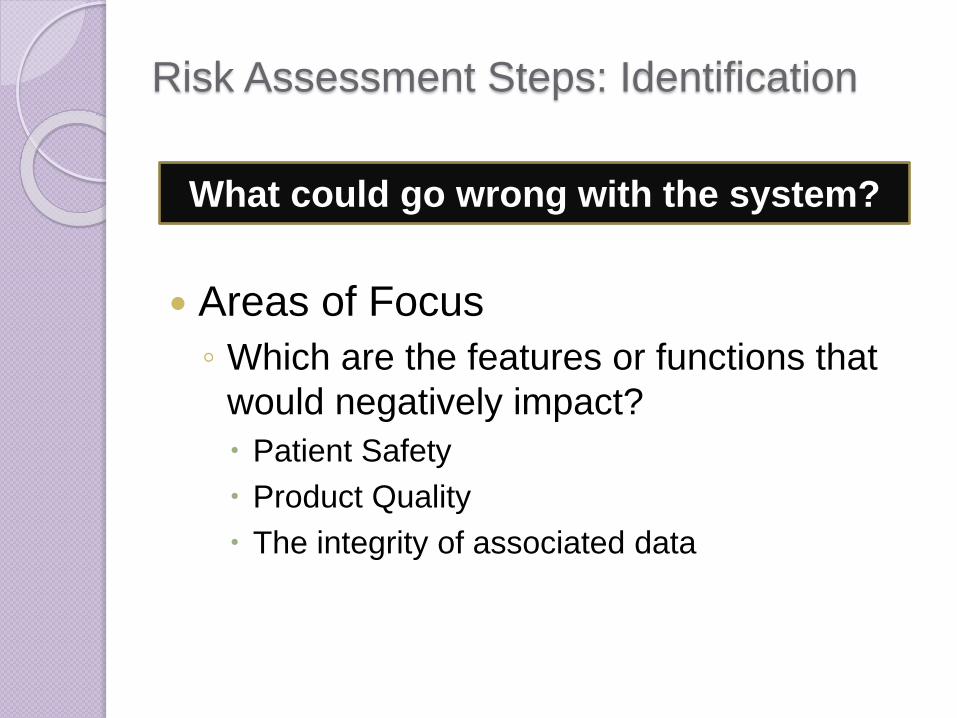
Risk Assessment Steps: Identification
Areas of Focus
◦ Which are the features or functions that
would negatively impact?
Patient Safety
Product Quality
The integrity of associated data
What could go wrong with the system?
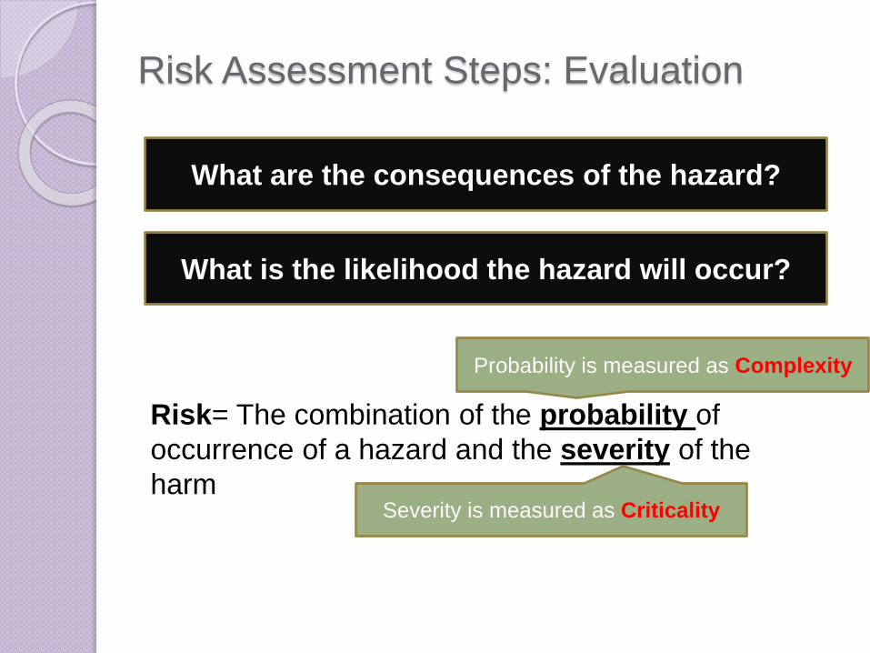
Risk Assessment Steps: Evaluation
What are the consequences of the hazard?
What is the likelihood the hazard will occur?
Risk= The combination of the probability of
occurrence of a hazard and the severity of the
harm
Probability is measured as Complexity
Severity is measured as Criticality
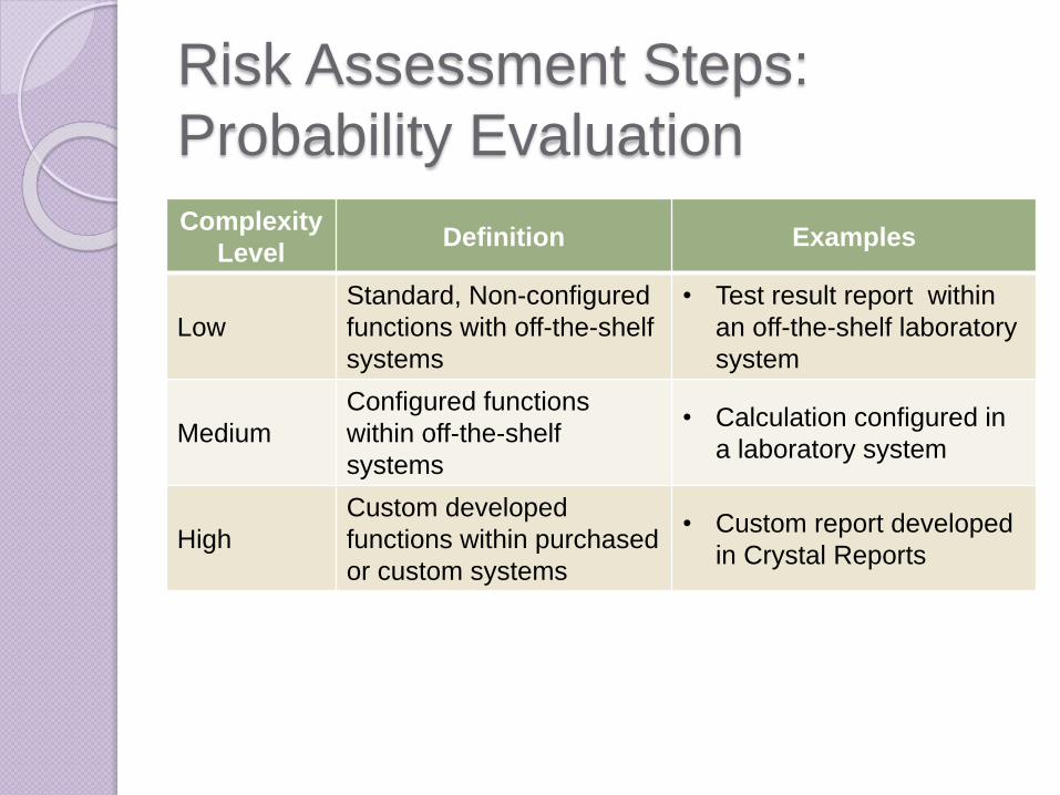
Risk Assessment Steps:
Probability Evaluation
Complexity
LevelDefinition Examples
Low
Standard, Non-configured
functions with off-the-shelf
systems
• Test result report within
an off-the-shelf laboratory
system
Medium
Configured functions
within off-the-shelf
systems
• Calculation configured in
a laboratory system
High
Custom developed
functions within purchased
or custom systems
• Custom report developed
in Crystal Reports
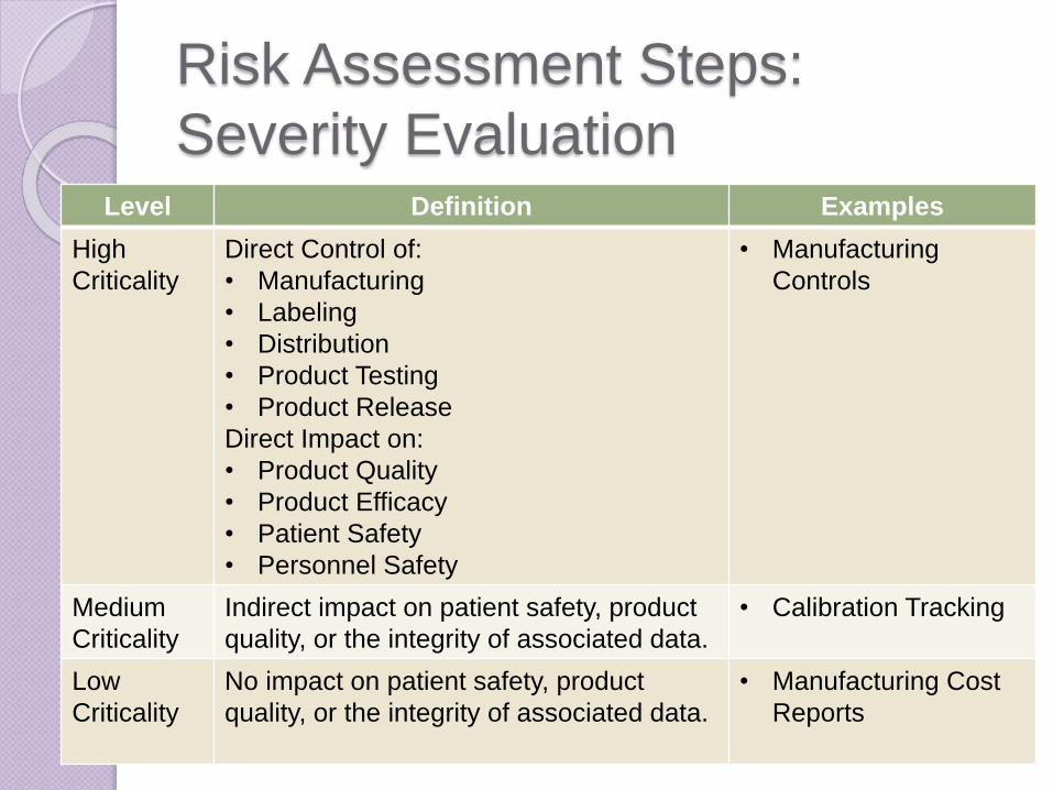
Risk Assessment Steps:
Severity Evaluation Level Definition Examples
High
Criticality
Direct Control of:
• Manufacturing
• Labeling
• Distribution
• Product Testing
• Product Release
Direct Impact on:
• Product Quality
• Product Efficacy
• Patient Safety
• Personnel Safety
• Manufacturing
Controls
Medium
Criticality
Indirect impact on patient safety, product
quality, or the integrity of associated data.
• Calibration Tracking
Low
Criticality
No impact on patient safety, product
quality, or the integrity of associated data.
• Manufacturing Cost
Reports
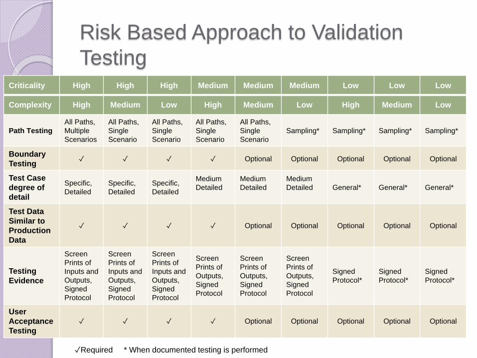
Risk Based Approach to Validation
TestingCriticality High High High Medium Medium Medium Low Low Low
Complexity High Medium Low High Medium Low High Medium Low
Path Testing
All Paths,
Multiple
Scenarios
All Paths,
Single
Scenario
All Paths,
Single
Scenario
All Paths,
Single
Scenario
All Paths,
Single
Scenario
Sampling* Sampling* Sampling* Sampling*
Boundary
Testing✓ ✓ ✓ ✓ Optional Optional Optional Optional Optional
Test Case
degree of
detail
Specific,
Detailed
Specific,
Detailed
Specific,
Detailed
Medium
Detailed
Medium
Detailed
Medium
Detailed General* General* General*
Test Data
Similar to
Production
Data
✓ ✓ ✓ ✓ Optional Optional Optional Optional Optional
Testing
Evidence
Screen
Prints of
Inputs and
Outputs,
Signed
Protocol
Screen
Prints of
Inputs and
Outputs,
Signed
Protocol
Screen
Prints of
Inputs and
Outputs,
Signed
Protocol
Screen
Prints of
Outputs,
Signed
Protocol
Screen
Prints of
Outputs,
Signed
Protocol
Screen
Prints of
Outputs,
Signed
Protocol
Signed
Protocol*
Signed
Protocol*
Signed
Protocol*
User
Acceptance
Testing
✓ ✓ ✓ ✓ Optional Optional Optional Optional Optional
✓Required * When documented testing is performed
Risk Based Approach to Validation
DocumentationCriticality High High High Medium Medium Medium Low Low Low
Complexity High Medium Low High Medium Low High Medium Low
Change
Request✓ ✓ ✓ ✓ ✓ ✓ ✓ ✓ ✓
Risk
Assessment✓ ✓ ✓ ✓ ✓ ✓ ✓ ✓ ✓
Project Plan ✓ ✓ ✓ ✓ ✓ Optional Optional Optional Optional
Validation
Plan✓ ✓ ✓ ✓ ✓ Optional Optional Optional Optional
User
Requirements✓ ✓ ✓ ✓ ✓ Optional Optional Optional Optional
Functional
Specification
✓
Highly
Detailed
✓
Highly
Detailed
✓
Highly
Detailed
✓
Medium
Detail
✓
Medium
Detail
✓
Medium
Detail
Optional
Low Detail
Optional
Low Detail
Optional
Low Detail
System
Design
Documents
✓ ✓ N/A ✓ ✓ N/A Optional Optional N/A
Test Plan ✓ ✓ ✓ Optional Optional Optional Optional Optional Optional
✓Required * When documented testing is performed
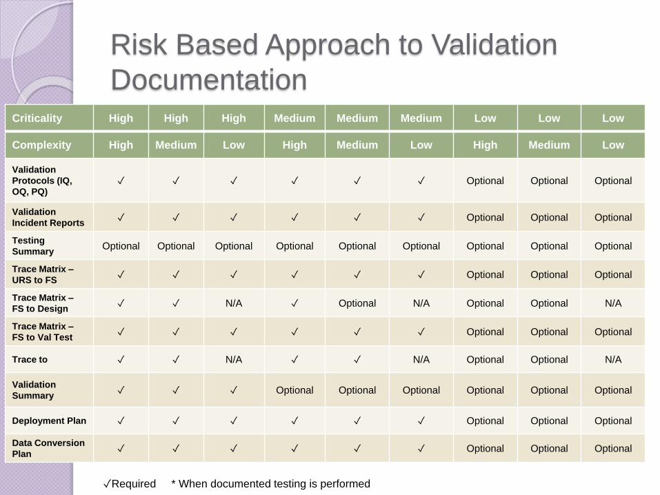
Risk Based Approach to Validation
DocumentationCriticality High High High Medium Medium Medium Low Low Low
Complexity High Medium Low High Medium Low High Medium Low
Validation
Protocols (IQ,
OQ, PQ)✓ ✓ ✓ ✓ ✓ ✓ Optional Optional Optional
Validation
Incident Reports✓ ✓ ✓ ✓ ✓ ✓ Optional Optional Optional
Testing
SummaryOptional Optional Optional Optional Optional Optional Optional Optional Optional
Trace Matrix –
URS to FS✓ ✓ ✓ ✓ ✓ ✓ Optional Optional Optional
Trace Matrix –
FS to Design✓ ✓ N/A ✓ Optional N/A Optional Optional N/A
Trace Matrix –
FS to Val Test✓ ✓ ✓ ✓ ✓ ✓ Optional Optional Optional
Trace to ✓ ✓ N/A ✓ ✓ N/A Optional Optional N/A
Validation
Summary✓ ✓ ✓ Optional Optional Optional Optional Optional Optional
Deployment Plan ✓ ✓ ✓ ✓ ✓ ✓ Optional Optional Optional
Data Conversion
Plan✓ ✓ ✓ ✓ ✓ ✓ Optional Optional Optional
✓Required * When documented testing is performed
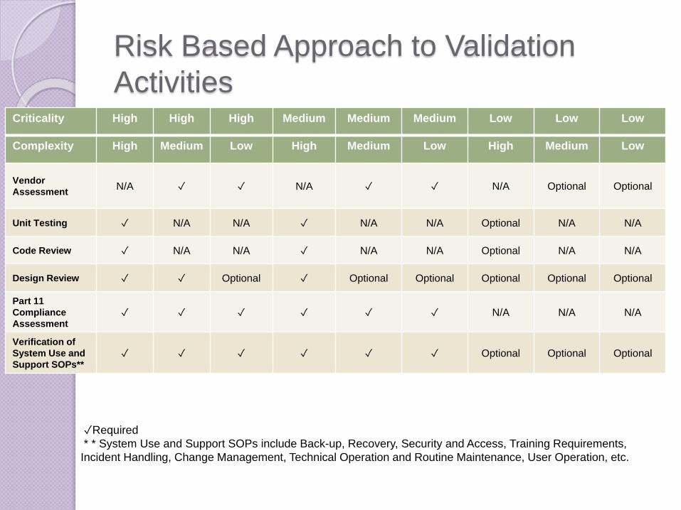
Risk Based Approach to Validation
ActivitiesCriticality High High High Medium Medium Medium Low Low Low
Complexity High Medium Low High Medium Low High Medium Low
Vendor
AssessmentN/A ✓ ✓ N/A ✓ ✓ N/A Optional Optional
Unit Testing ✓ N/A N/A ✓ N/A N/A Optional N/A N/A
Code Review ✓ N/A N/A ✓ N/A N/A Optional N/A N/A
Design Review ✓ ✓ Optional ✓ Optional Optional Optional Optional Optional
Part 11
Compliance
Assessment✓ ✓ ✓ ✓ ✓ ✓ N/A N/A N/A
Verification of
System Use and
Support SOPs**✓ ✓ ✓ ✓ ✓ ✓ Optional Optional Optional
✓Required
* * System Use and Support SOPs include Back-up, Recovery, Security and Access, Training Requirements,
Incident Handling, Change Management, Technical Operation and Routine Maintenance, User Operation, etc.

Risk Assessment Steps:
Risk Mitigation through Procedures
SOP Risk Mitigation based of Risk Classification
Vendor Assessment Vendor Assessment Method
Audit Trail Audit Trail Requirement
Security and Access Password Change Frequency
Training
RequirementsTraining Format
Back-up Backup Location and Backup Media Audit
Frequency
Alternate RecordsAlternate Procedure Required or Second
Person Verification Required
Incident Handling Resolution Priority
Risk Analysis Methods: GAMP

Risk Analysis Methods: FMECAFailure Mode Effect Criticality Analysis
C = P x S X N◦ C: Criticality
◦ P:Probability of Failure Mode
◦ S:Severity
◦ N:Probability of Not Detecting Failure Mode or Effect
Greater
Criticality =
Higher Risk
FMECA makes
you think
through the
consequences
of failures

PART 4: CSV PROJECT DELIVERABLES

Standard Validation Project

PlanningPlanning Reporting
Requirements TestingUser Requirement
Specification
Functional
Specification
Design/Configuration
Specification
Functional Testing
Build/Configuration
Testing
Build/Configuration
Planning
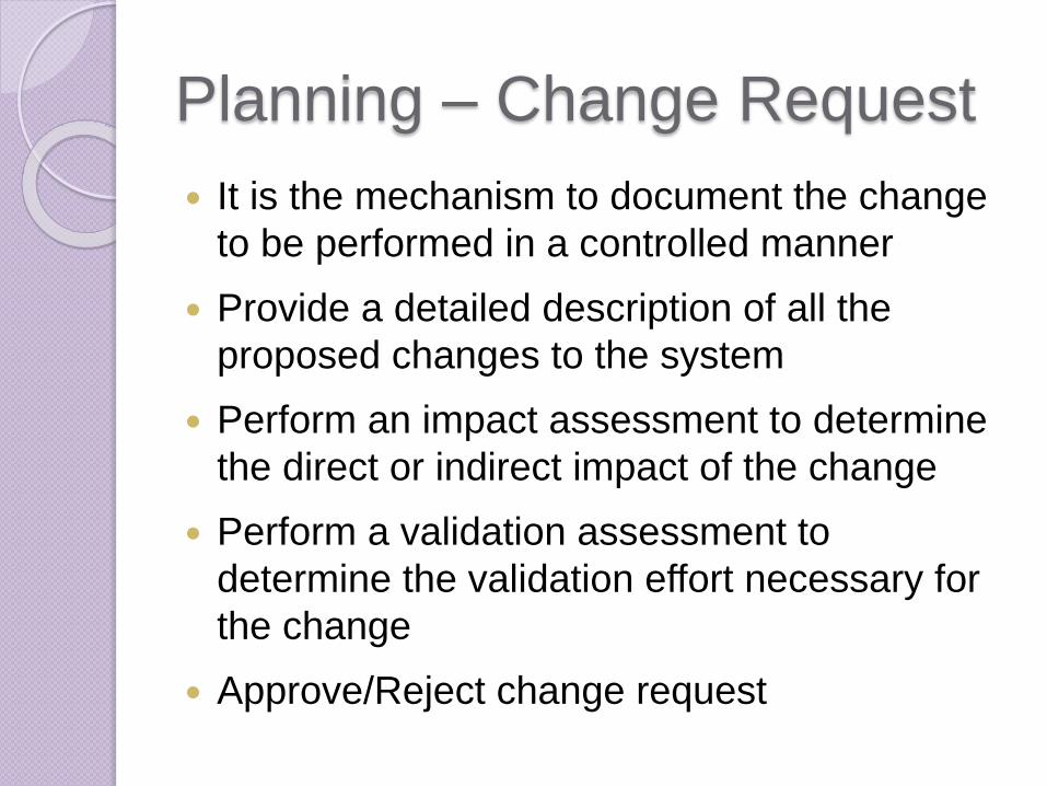
Planning – Change Request
It is the mechanism to document the change
to be performed in a controlled manner
Provide a detailed description of all the
proposed changes to the system
Perform an impact assessment to determine
the direct or indirect impact of the change
Perform a validation assessment to
determine the validation effort necessary for
the change
Approve/Reject change request

Planning – Project Plan
Approved document used to establish
project organization, execution and
control
Content may be covered in the project
charter
Defines project stakeholders and roles

Validation Plan
Defines the validation strategy
including:
◦ Roles and Responsibilities
◦ System Description
◦ Validation Scope
◦ Project Deliverables
◦ Level of Testing
◦ Project Timeline

Planning – Additional
Deliverables
Initial Risk Assessment◦ Initial Risk Assessment is likely to
focus in important risk to GxP and to the business process
Supplier Assessment◦ Provides information on product
including risks and controls

Planning – Test Plan
The test plan should be approved by Technical,
Business and Quality Assurance experts
Documents the strategy that will be used to verify
and ensure that the system meets its design
specification and other requirements
Includes a detailed list of the testing to be
performed
Defines different system environments:
Development Validation Production Training
Requirements SpecificationsPlanning Reporting
Requirements TestingUser Requirement
Specification
Functional
Specification
Design/Configuration
Specification
Functional Testing
Build/Configuration
Testing
Build/Configuration
User
/Functional
Specification
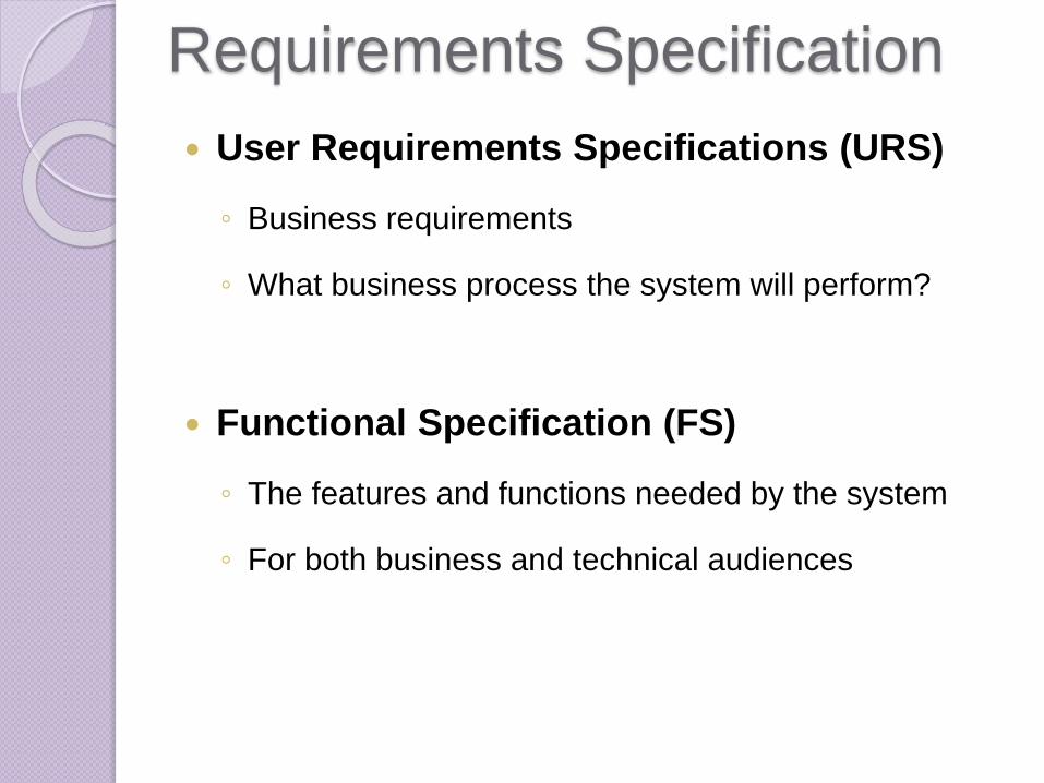
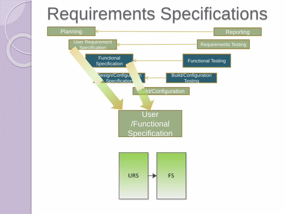
Requirements Specification
User Requirements Specifications (URS)
◦ Business requirements
◦ What business process the system will perform?
Functional Specification (FS)
◦ The features and functions needed by the system
◦ For both business and technical audiences

User Requirements vs. Functional
Requirements
User Requirements
Non-technical statements of
what the user needs the system
to do for them
Includes service and support
requirements and constraints
Audience is business users
Functional Requirements
Detailed statements of how the
system will interact and react to
users to accomplish what they need
Includes specifics such as speed,
size, back up frequency, etc.
Audience is business users and
technical individuals
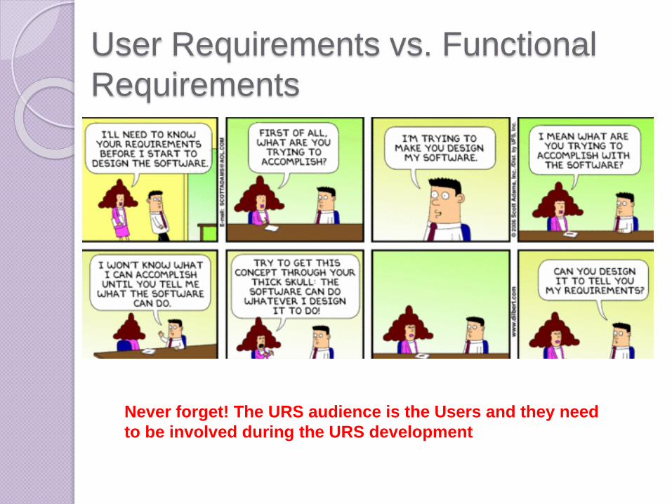
User Requirements vs. Functional
Requirements
Never forget! The URS audience is the Users and they need
to be involved during the URS development
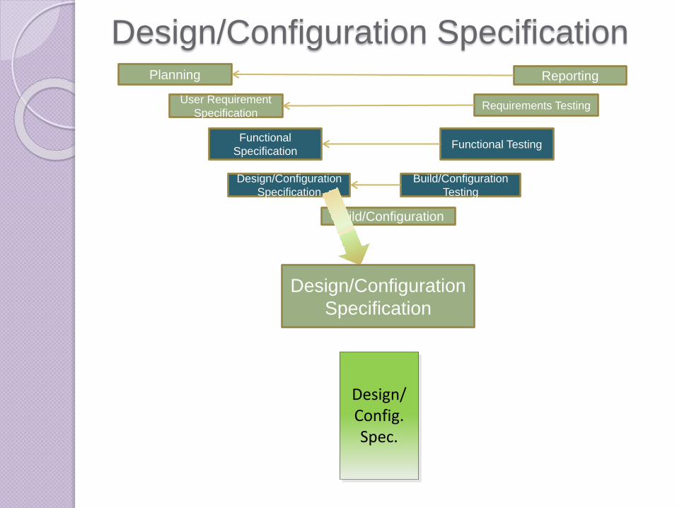
Design/Configuration SpecificationPlanning Reporting
Requirements TestingUser Requirement
Specification
Functional
Specification
Design/Configuration
Specification
Functional Testing
Build/Configuration
Testing
Build/Configuration
Design/Configuration
Specification
Design/Config.Spec.

Design/Configuration Specification
Design Specification
◦ Includes how the features and functions identified in
the Functional Specification will be implemented
◦ Includes the logical structure and processing steps
◦ Level of detail depends on the severity and
complexity of the system
Configuration Specification
◦ Should be used for Custom Off The Shelf (COTS)
systems
◦ Includes customizations and configurations

Design Review Design reviews include examination of:
◦ Development standards
◦ Development plans
◦ Requirements specifications
◦ Design specifications
◦ All other documents and activities associated with the
project
◦ Verification results from each previous stage of the life
cycle
◦ History of previously reported issues for existing
software

Build/ConfigurationPlanning Reporting
Requirements TestingUser Requirement
Specification
Functional
Specification
Design/Configuration
Specification
Functional Testing
Build/Configuration
Testing
Build/Configuration
Build. Config.

Build/Configuration
Implement configuration per:
◦ Design/Configuration Specification
◦ Coding guidelines - coding conventions
regarding clarity, style, complexity
management and commenting
Source code evaluation
◦ Code inspections, walkthroughs and
reviews by peers and technical managers
TestingPlanning Reporting
Requirements TestingUser Requirement
Specification
Functional
Specification
Design/Configuration
Specification
Functional Testing
Build/Configuration
Build/Configuration
Testing

What is Computer System
Validation?
Confirmation by examination and
provision of objective evidence that
software specifications conform to user
needs and intended uses, and that the
particular requirements implemented
through software can be consistently
fulfilled.
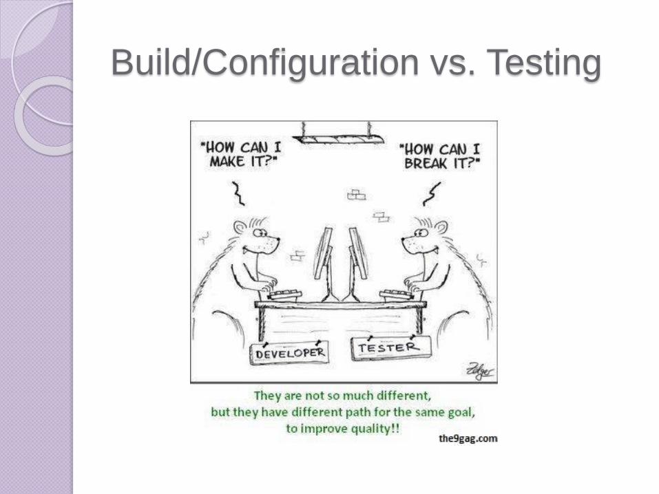
Build/Configuration vs. Testing

Principles of Testing
A good test case has:
High probability of exposing an error
◦ Steady-State Testing (Normal Conditions)
◦ Stress Testing (Abnormal Conditions)
Predefined Expected test outcome
Independence from Coding
Test documentation permits independent confirmation of the Pass/Fail status of a test outcome during subsequent review

Types of Testing-
Structural vs Functional
Structural Testing (White-Box Testing)
◦ Takes into account the internal structure of a system.
◦ Testing of all Branching, Path, Statements.
Functional Testing (Black-Box Testing)
◦ Focuses on outputs generated in response to
selected inputs
◦ Focuses on compliance to functional requirements
◦ Ignores the internal structure of a system
Types of Testing
Unit Testing - Verifies the implementation of the
DS for one software element
Integration Testing - Verifies interactions between
software and hardware elements in orderly
progression until the entire system has been
tested.
System Testing – Verifies that integrated
hardware and software system meets specified
requirements.
Acceptance Testing – Verifies if the system
satisfies its acceptance criteria and enables the
customer to accept the system.
Testing Techniques
Path Testing – Coverage of each
logical path
Branch Testing – For each decision
point, each possible branch is
executed at least once
Worst Case Testing Techniques
Special Case Testing – Using input values or
types likely to cause program errors
Volume Testing – Evaluates system’s ability to
manage the maximum amount of data over a
period of time in an orderly fashion
Boundary Test – Testing input and output values
just below and above the defined limits
Stress Testing – Evaluates system at the limits or
beyond each requirement

Writing Test Cases
Include Test description and Objectives, Pre-
requisites.
Types of instructions:
◦ Setup steps
◦ Test Steps
◦ Navigation Steps
Cover all testing specified in Test Plan
Provide sufficient details (but not too much) for
the experience level of the tester.

Writing Test Cases
Minimum Test Requirements:
◦ Test Steps or Actions
◦ Expected Results
◦ Actual Results
◦ Pass/Fail
◦ Initials and Date
◦ Comments
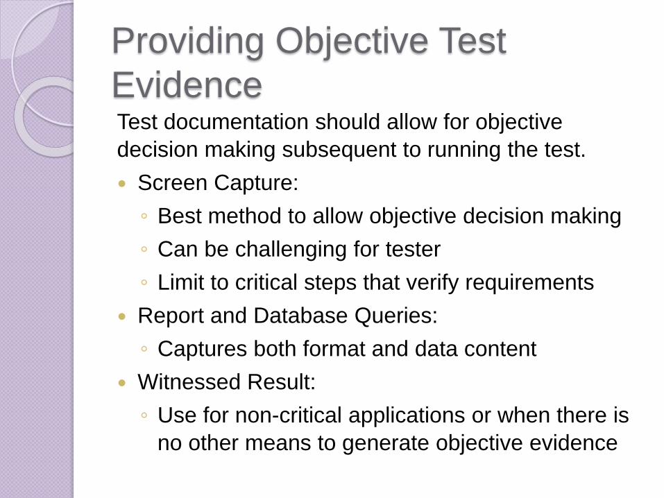
Providing Objective Test
EvidenceTest documentation should allow for objective
decision making subsequent to running the test.
Screen Capture:
◦ Best method to allow objective decision making
◦ Can be challenging for tester
◦ Limit to critical steps that verify requirements
Report and Database Queries:
◦ Captures both format and data content
Witnessed Result:
◦ Use for non-critical applications or when there is
no other means to generate objective evidence
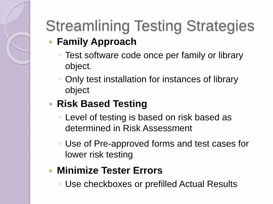
Streamlining Testing Strategies Family Approach
◦ Test software code once per family or library
object.
◦ Only test installation for instances of library
object
Risk Based Testing
◦ Level of testing is based on risk based as
determined in Risk Assessment
◦ Use of Pre-approved forms and test cases for
lower risk testing
Minimize Tester Errors
◦ Use checkboxes or prefilled Actual Results
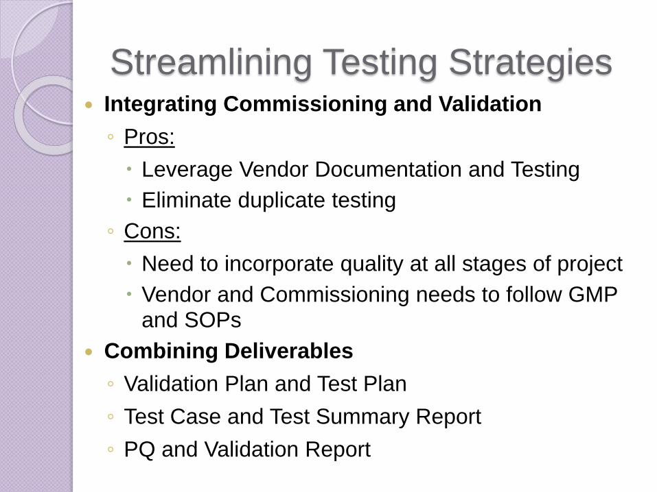
Streamlining Testing Strategies Integrating Commissioning and Validation
◦ Pros:
Leverage Vendor Documentation and Testing
Eliminate duplicate testing
◦ Cons:
Need to incorporate quality at all stages of project
Vendor and Commissioning needs to follow GMP and SOPs
Combining Deliverables
◦ Validation Plan and Test Plan
◦ Test Case and Test Summary Report
◦ PQ and Validation Report
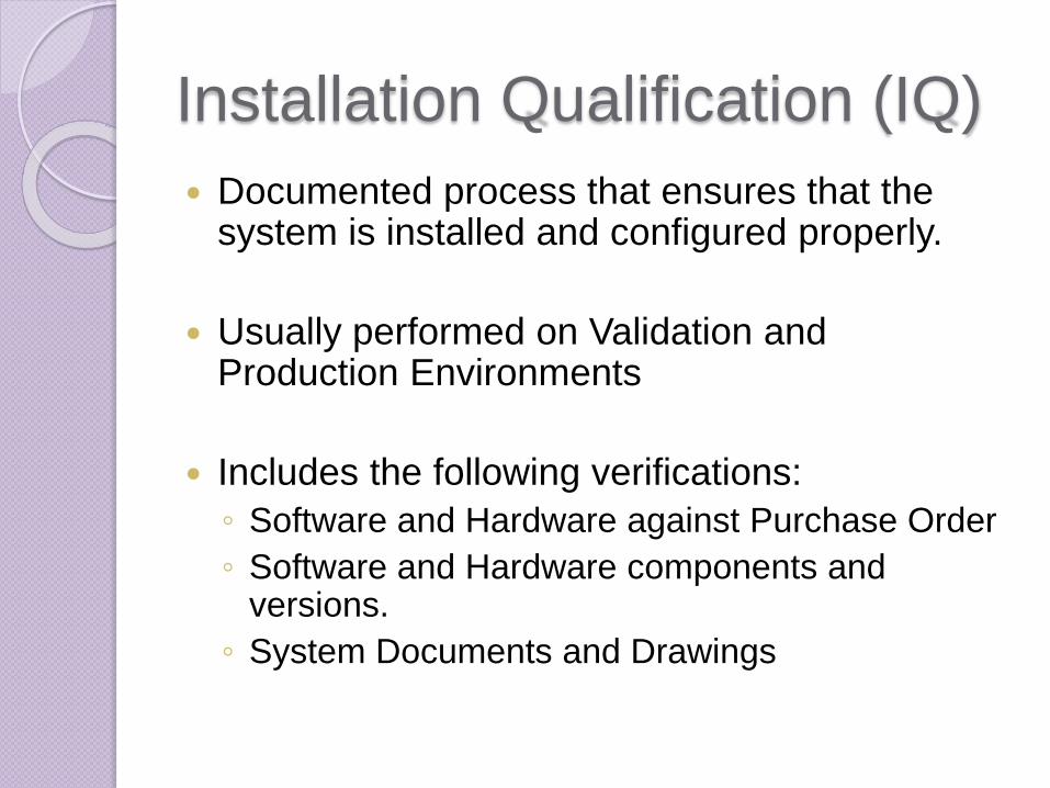
Installation Qualification (IQ)
Documented process that ensures that the system is installed and configured properly.
Usually performed on Validation and Production Environments
Includes the following verifications:
◦ Software and Hardware against Purchase Order
◦ Software and Hardware components and versions.
◦ System Documents and Drawings
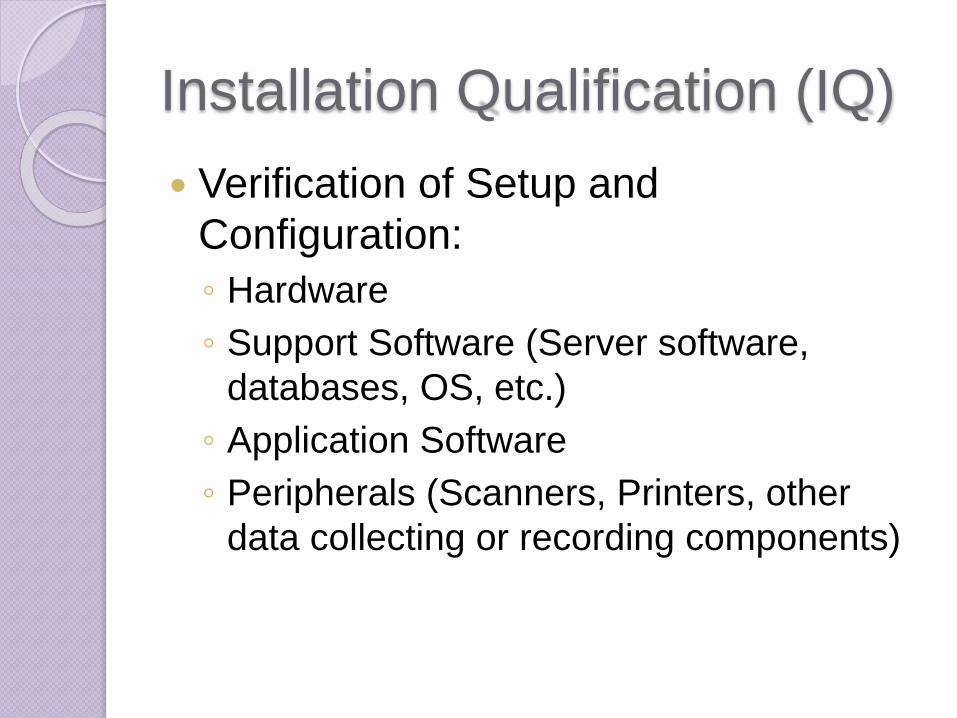
Installation Qualification (IQ)
Verification of Setup and
Configuration:
◦ Hardware
◦ Support Software (Server software,
databases, OS, etc.)
◦ Application Software
◦ Peripherals (Scanners, Printers, other
data collecting or recording components)
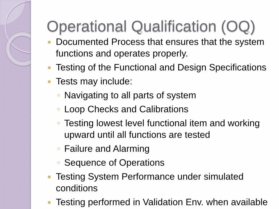
Operational Qualification (OQ) Documented Process that ensures that the system
functions and operates properly.
Testing of the Functional and Design Specifications
Tests may include:
◦ Navigating to all parts of system
◦ Loop Checks and Calibrations
◦ Testing lowest level functional item and working
upward until all functions are tested
◦ Failure and Alarming
◦ Sequence of Operations
Testing System Performance under simulated
conditions
Testing performed in Validation Env. when available

Performance Qualification (PQ)
Documented process that ensures
that the system perform to
business/user requirements
Testing of URS
Tests may include:
◦ Verification that the system has the
features needed to support automation of
the business operations
◦ Testing following processes in SOPs
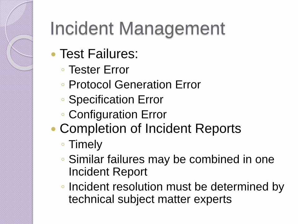
Incident Management
Test Failures:◦ Tester Error
◦ Protocol Generation Error
◦ Specification Error
◦ Configuration Error
Completion of Incident Reports◦ Timely
◦ Similar failures may be combined in one Incident Report
◦ Incident resolution must be determined by technical subject matter experts

Incident Management
Resolution (subject to QA SOP and approver) :
◦ Protocol Generation Error – If evidence is correct no
re-testing is required
◦ Tester Error – If evidence is correct no re-testing is
required. If steps were not followed correctly, re-
testing is required.
◦ Specification Error – Update documentation. If
evidence is correct no re-testing is required.
◦ Configuration Error – Update system configuration. If
required, update specification. Re-testing is required.
Evaluate if regression testing is required.
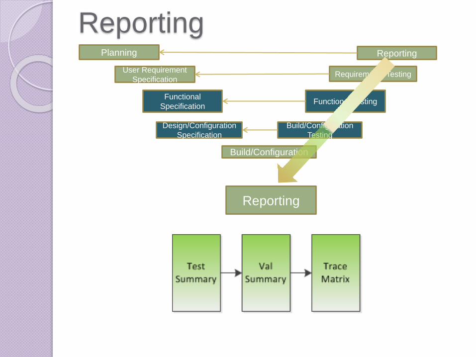
ReportingPlanning Reporting
Requirements TestingUser Requirement
Specification
Functional
Specification
Design/Configuration
Specification
Functional Testing
Build/Configuration
Testing
Build/Configuration
Reporting

Test Summary
Summary of all testing activities and results
List all incident or deviations from test cases or test plan that occurred during testing activities
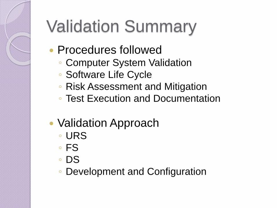
Validation Summary
Procedures followed◦ Computer System Validation
◦ Software Life Cycle
◦ Risk Assessment and Mitigation
◦ Test Execution and Documentation
Validation Approach◦ URS
◦ FS
◦ DS
◦ Development and Configuration
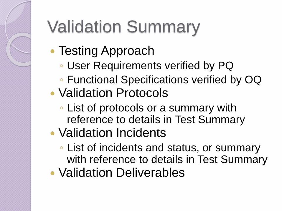
Validation Summary
Testing Approach◦ User Requirements verified by PQ
◦ Functional Specifications verified by OQ
Validation Protocols◦ List of protocols or a summary with
reference to details in Test Summary
Validation Incidents◦ List of incidents and status, or summary
with reference to details in Test Summary
Validation Deliverables

Validation Summary
Additional Quality Assurance activities:◦ User Manuals
◦ Training Materials
◦ SOPs for system use and system support
Final Conclusion◦ State the current status of the system
◦ System is now fit for use and released
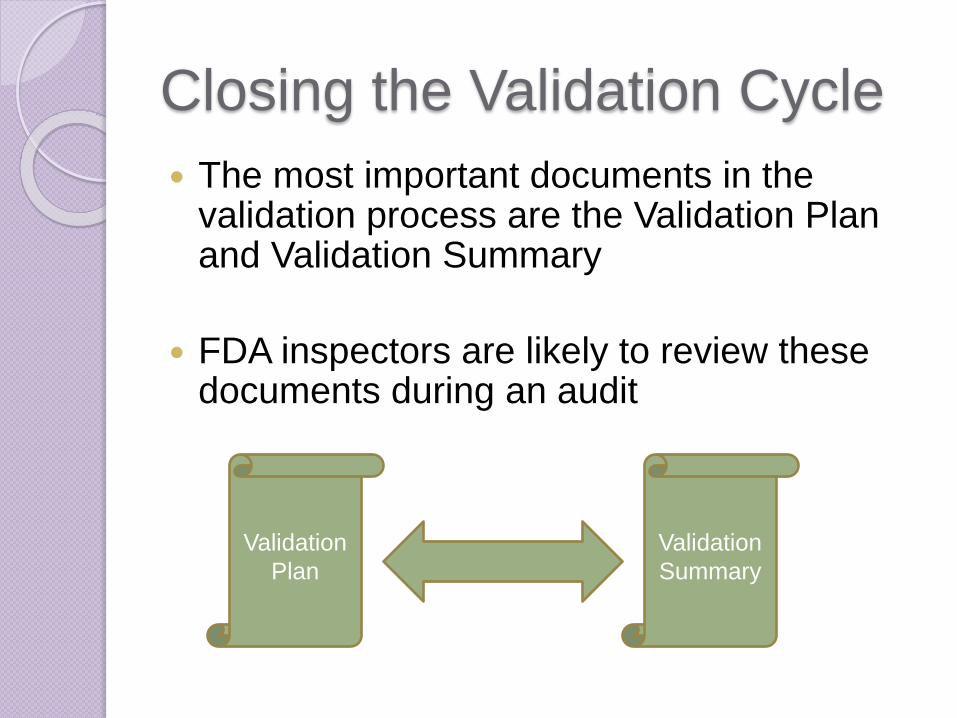
Closing the Validation Cycle
The most important documents in the validation process are the Validation Plan and Validation Summary
FDA inspectors are likely to review these documents during an audit
Validation
Plan
Validation
Summary
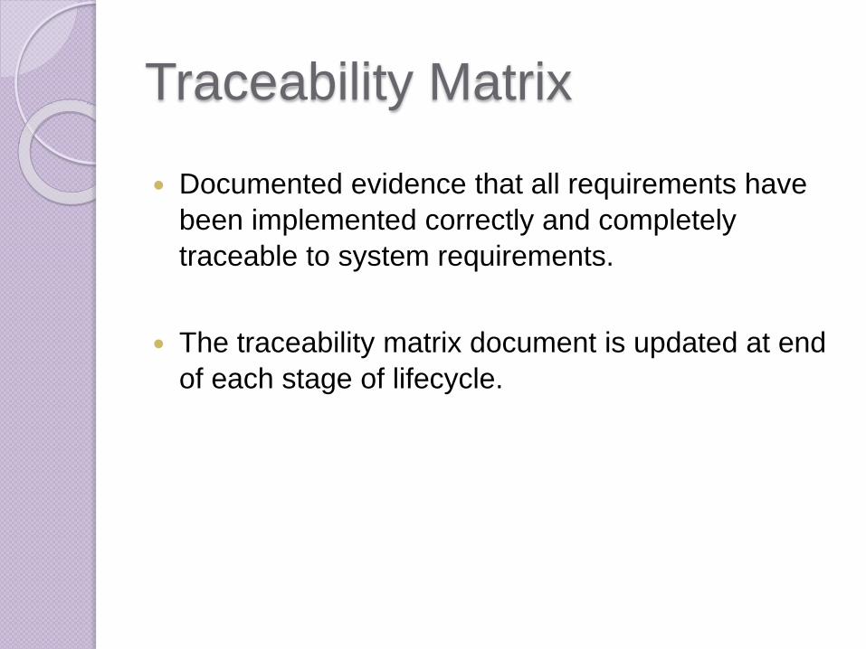
Traceability Matrix
Documented evidence that all requirements have
been implemented correctly and completely
traceable to system requirements.
The traceability matrix document is updated at end
of each stage of lifecycle.

Traceability Matrix
Testing (IQ,OQ,PQ)
User Requirements Specification
Functional Specification
Design Specification
PART 5: INTERACTIVE EXERCISE
Define Project:
Install Environmental Monitoring System
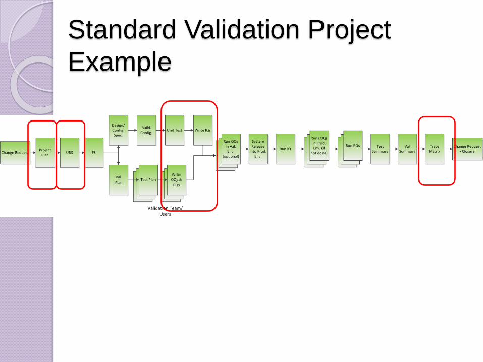
Standard Validation Project
Example
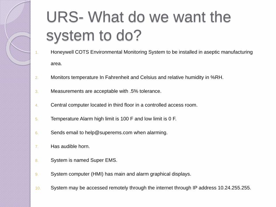
URS- What do we want the
system to do?1. Honeywell COTS Environmental Monitoring System to be installed in aseptic manufacturing
area.
2. Monitors temperature In Fahrenheit and Celsius and relative humidity in %RH.
3. Measurements are acceptable with .5% tolerance.
4. Central computer located in third floor in a controlled access room.
5. Temperature Alarm high limit is 100 F and low limit is 0 F.
6. Sends email to [email protected] when alarming.
7. Has audible horn.
8. System is named Super EMS.
9. System computer (HMI) has main and alarm graphical displays.
10. System may be accessed remotely through the internet through IP address 10.24.255.255.
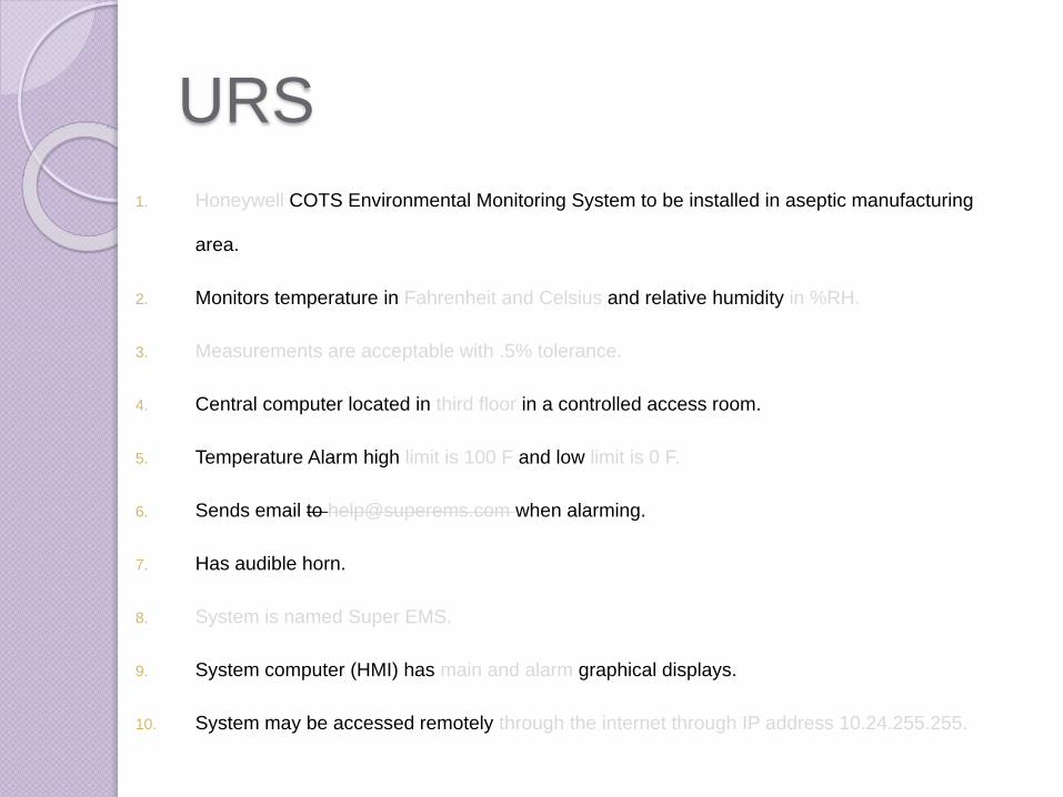
URS
1. Honeywell COTS Environmental Monitoring System to be installed in aseptic manufacturing
area.
2. Monitors temperature in Fahrenheit and Celsius and relative humidity in %RH.
3. Measurements are acceptable with .5% tolerance.
4. Central computer located in third floor in a controlled access room.
5. Temperature Alarm high limit is 100 F and low limit is 0 F.
6. Sends email to [email protected] when alarming.
7. Has audible horn.
8. System is named Super EMS.
9. System computer (HMI) has main and alarm graphical displays.
10. System may be accessed remotely through the internet through IP address 10.24.255.255.
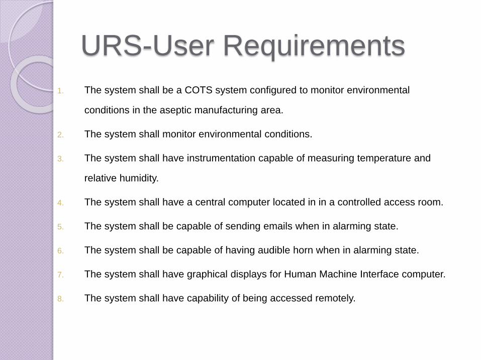
URS-User Requirements
1. The system shall be a COTS system configured to monitor environmental
conditions in the aseptic manufacturing area.
2. The system shall monitor environmental conditions.
3. The system shall have instrumentation capable of measuring temperature and
relative humidity.
4. The system shall have a central computer located in in a controlled access room.
5. The system shall be capable of sending emails when in alarming state.
6. The system shall be capable of having audible horn when in alarming state.
7. The system shall have graphical displays for Human Machine Interface computer.
8. The system shall have capability of being accessed remotely.
Risk Assessment Steps:
Probability Evaluation
Complexity
LevelDefinition Examples
Low
Standard, Non-configured
functions with off-the-shelf
systems
• Test result report within
an off-the-shelf laboratory
system
Medium
Configured functions
within off-the-shelf
systems
• Calculation configured in
a laboratory system
High
Custom developed
functions within purchased
or custom systems
• Custom report developed
in Crystal Reports
Honeywell
COTS
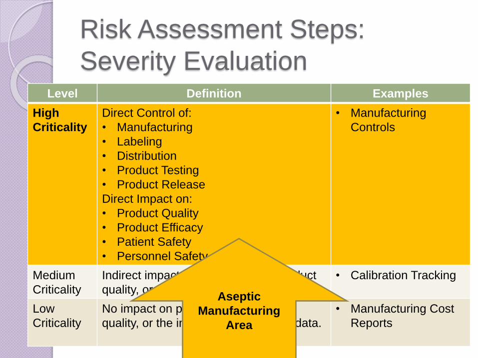
Risk Assessment Steps:
Severity Evaluation Level Definition Examples
High
Criticality
Direct Control of:
• Manufacturing
• Labeling
• Distribution
• Product Testing
• Product Release
Direct Impact on:
• Product Quality
• Product Efficacy
• Patient Safety
• Personnel Safety
• Manufacturing
Controls
Medium
Criticality
Indirect impact on patient safety, product
quality, or the integrity of associated data.
• Calibration Tracking
Low
Criticality
No impact on patient safety, product
quality, or the integrity of associated data.
• Manufacturing Cost
Reports
Aseptic
Manufacturing
Area

Risk Analysis
Risk Class = ?Risk Class = 1
Risk = ?Risk = High

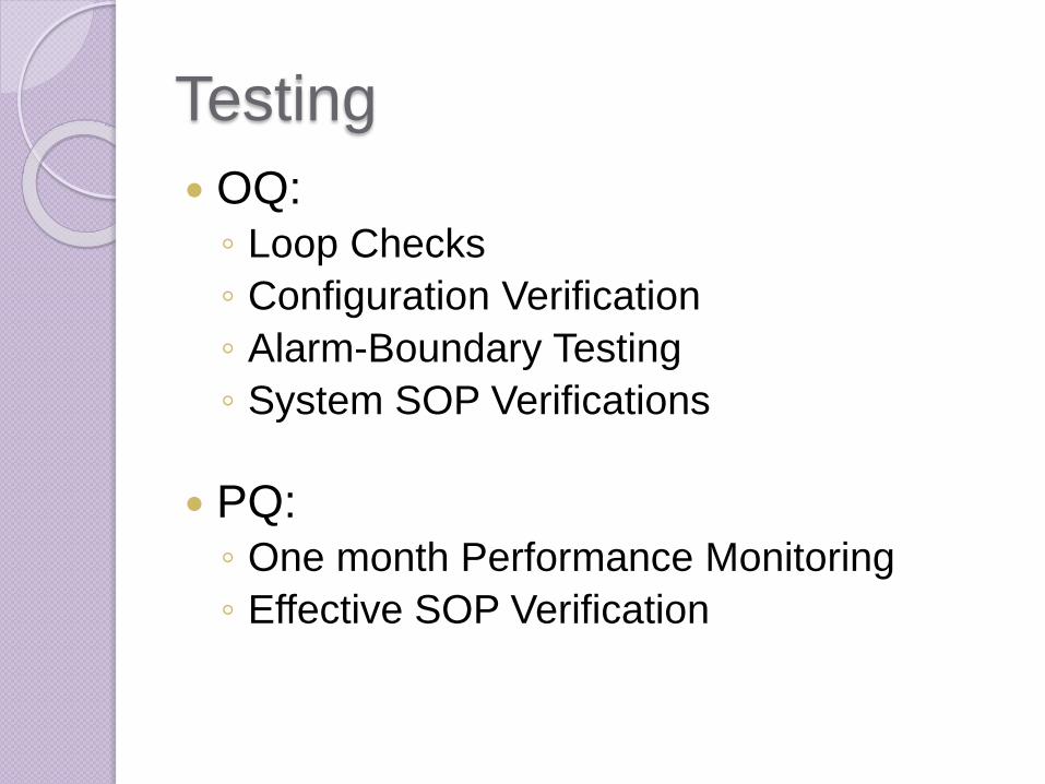
Testing
IQ:◦ Software Verification
◦ Hardware Verification
◦ Drawing Walk-downs
◦ Calibration Verification
◦ Code Transfer/Installation
◦ Graphic Display Navigation
◦ Environmental Conditions
Testing
OQ:◦ Loop Checks
◦ Configuration Verification
◦ Alarm-Boundary Testing
◦ System SOP Verifications
PQ:◦ One month Performance Monitoring
◦ Effective SOP Verification
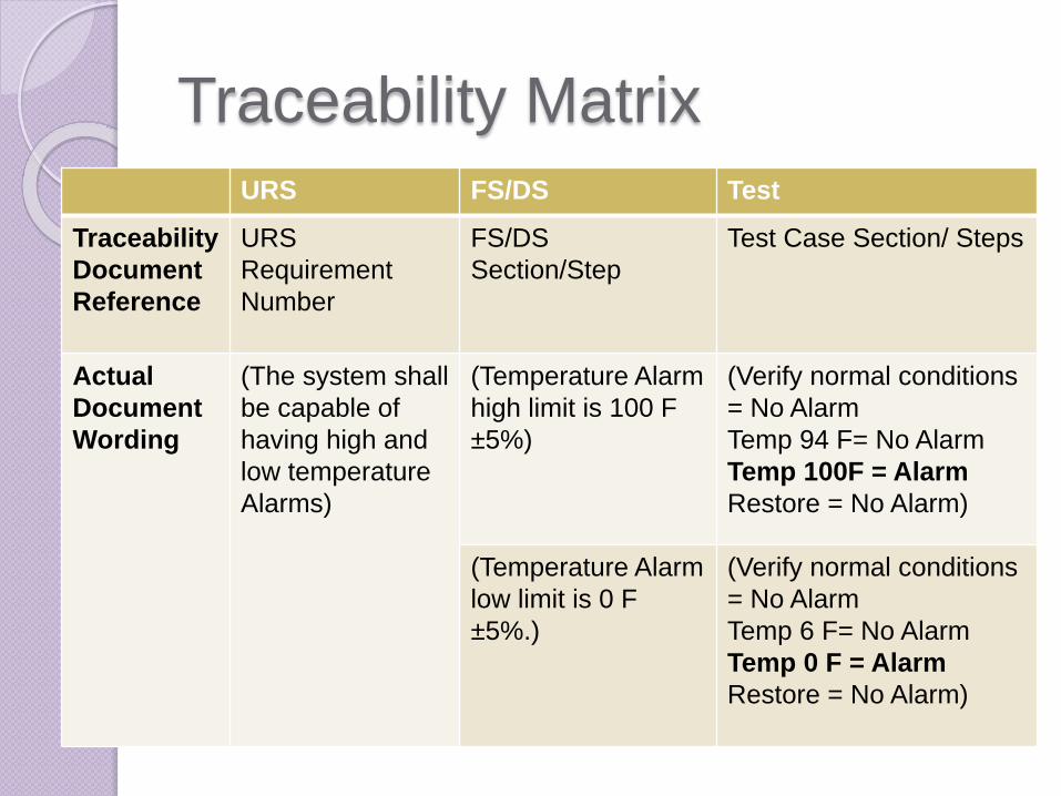
Traceability Matrix
URS FS/DS Test
Traceability
Document
Reference
URS
Requirement
Number
FS/DS
Section/Step
Test Case Section/ Steps
Actual
Document
Wording
(The system shall
be capable of
having high and
low temperature
Alarms)
(Temperature Alarm
high limit is 100 F
±5%)
(Verify normal conditions
= No Alarm
Temp 94 F= No Alarm
Temp 100F = Alarm
Restore = No Alarm)
(Temperature Alarm
low limit is 0 F
±5%.)
(Verify normal conditions
= No Alarm
Temp 6 F= No Alarm
Temp 0 F = Alarm
Restore = No Alarm)

Questions????