Embed Size (px)
Citation preview

Impedance Calculation and VerificationImpedance Calculation and Verification Impedance Calculation and VerificationImpedance Calculation and Verification
Karl Bane
Stanford Linear Accelerator CenterStanford Linear Accelerator CenterNovember 9, 2004

Outline of talkOutline of talk
• Longitudinal impedance calculations/measurements for - SLC damping rings (1988-95)—many SLAC contributors
- Dafne (1994-2000) –M. Zobov
- KEK’s ATF damping ring (2000-01)—ATF group
The longitudinal broad-band impedance of a ring can cause current dependent bunch lengthening, energy spread increase, and time dependent (e.g. bursting) behavior
IntroductionIntroduction

Programs for longitudinal impedance (broad-band)Programs for longitudinal impedance (broad-band)
• Short bunch wake: time domain programs like T2 and T3 in MAFIA
• Phase space tracking
•Linearized Vlasov equation solver for finding threshold (Oide)

SLC Damping Rings SLC Damping Rings
• 3 versions: (i) original, (ii) old (shielded bellows), (iii) new (current; new, smoother vacuum chamber)
• Nominal z~ 5 mm, half aperture a ~1 cm
• Old ring inductive (small objects dominated impedance); new ring resistive
Layout of north damping ring. Circumference is 35 m.
Cross-section of a bend chamber. Dashedcircle shows the size of a quad chamber.

• Old ring was inductive; generated a table of strength of inductive elements
• Pseudo-Green function: for a short Gaussian bunch (z= 1 mm) find an accurate wake; to be used in potential well/instability calculations; used T2 of MAFIA
Vertical profile of QF segment (top) and QD segment (bottom). There are 20 of each in the ring. Dashes represent non-cylindrically symmetric objects.The inductive vacuum chamber objects.
The total yields |Z/n|= 2.6 .
Calculations: old ringCalculations: old ring

Pseudo-Green function Fourier transform of Green function. Dotsgive result when bellows are shielded.
Green function convolved with z= 6 mm Gaussian bunch. Wake is inductive.
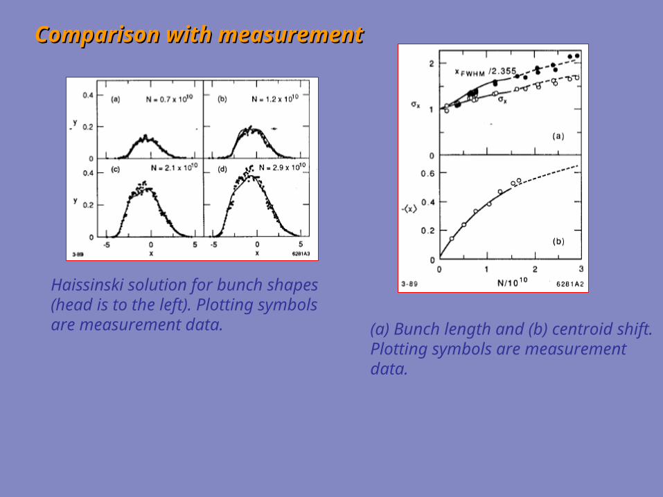
Comparison with measurementComparison with measurement
Haissinski solution for bunch shapes(head is to the left). Plotting symbols are measurement data. (a) Bunch length and (b) centroid shift.
Plotting symbols are measurement data.

TrackingTracking
(a) Turn-by-turn skew when N= 3.5e10. (b) Rms when N= 5e10.
Fourier transforms of plots at left.
Position of peaks in skew signal FT vs. N.“Sextupole” mode seen in measurements with same d/dN.

Bunch shape at two phases 180 deg. apart.
N= 3.5e10
Shape of the mode: density of phase space when subtracted from the average.

New ringNew ring
New bend-to-quad transition
New Green function
Potential well calculation
• New, smoother vacuum chamberwas installed

Vlasov equation mode calculation. Unstable mode begins at N= 1e10 with = 1.95s0. New type of mode.
Shape of unstable mode

SLC damping ring summarySLC damping ring summary
original 1.1e10 1.5e10
old 2.0e10 3.0e10
new 2.0e10* 1.5e10
threshold version calculated measured
“sextupole” mode
quadrupole mode
*if add 2nH (0.1) inductance
• How to understand: from old to new ring reduced the impedance and threshold dropped? old, inductive ring—strong mode—tune spread—weak modes Landau damped new, resistive ring—weak mode—little tune spread—no Landau damping
• Note: old ring, SLC operation limited to 3e10, new ring—5e10

DANE Vacuum Chamber RF Design
M. ZobovThe DANE vacuum chamber is complicated. Despite a short collider circumference of 97 m the vacuum chamber of each ring contains:
• Two 10 m long interaction regions• Four 5 m long narrow gap wiggler vacuum
chambers• Straight sections fo allocation of RF cavities,
injection kickers, longitudinal feedback kickers, transverse feedback kickers
• Tapers connecting straight sections, bending arcs, wiggler sections, interaction regions.
• Many others components
Being a high current collider all the vacuum chamber components were designed to avoid beam instabilities and excessive power losses. New designs and ideas were incorporated in:
• Main RF cavity
• Third harmonic cavity
• Longitudinal feedback kicker
• Injection kicker
• Transverse feedback kicker
• Beam position monitor
• Direct current monitor
• Interaction point shield
• Bellows
• Pumping ports
• Clearing electrodes
• Tapers
• Flanges
• Valves
• Scrapers
• Etc…
Numerical Codes Used:
ABCI, URMEL, MAFIA (2.04), HFSS

DANE Main RF Cavity (Particle Accelerators, Vol. 48, p.213 (1995)
Principal Design Features
-Rounded body: simple mechanical design, no multipacting
-Long tapers: low broad-band impedance, lower RF losses
-HOM positions far from principal beam harmonics
-Damping waveguides with broad-band transitions to external loadings
-No dissipative materials under high vacuum
Longitudinal Feedback Kicker
• Purpose: – used to provide correcting longitudinal kick
• Design Features:– heavily loaded pill-box cavity– 6 ridged wave guides rounded to fit cavity shape– special transitions to coaxial feed through
• Advantages– High broad-band shunt impedance– All HOM are damped
• Publications– Part. Accel. 52: 95-113, 1996
(>30 citations in HEP)
• Successful Experience in:– DANE, KEKB, BESSYII, PLS, SLS,
HLS,ELETTRA– PEP-II (upgrade, December 2003)– SPEAR-3, CESR (considered)
DA NE 3rd Harmonic RF Cavity
• Main Purpose:– Bunch length control for lifetime improvement– Additional Landau damping
• Design Features:– Single mode cavity. All HOM propagate and are
damped by ferrite absorber– KEKB ferrite absorber is used which creates a
coaxial together with the beam pipe– Taper is used for gradual matching between the
cavity pipe and the coaxial absorber.
• Publications– Nucl. Instrum. Meth. A354: 215-223, 1995– Phys.Rev. ST Accel. Beams 6: 074401, 2003
Short Shielded Bellows
- There are 20 bellows placed in straight sections. They are 45 mm long and must provide 10 mm longitudinal expansion (Short Bellows)
- The bellows screen is made of Mini Bellows with a diameter of 7.9 mm and paced by 1 mm fitting the vacuum chamber cross section.
- The 1-3 cm long bunch does not “see” the Mini Bellows corrugations. Indeed, no any notable coupling impedance has been measured till 3.5 GHz
A r c V a c u u m C h a m b e r
A s y s t e m o f l o n g g r a d u a l t r a n s i t i o n s b e t w e e n d i f f e r e n t a r c v a c u u m c h a m b e r c r o s s - s e c t i o n s i s u s e d t o m i n i m i z e t h e c o u p l i n g i m p e d a n c e

Bunch Lengthening in DANETypical Measured Bunch Distributions
190
200
210
220
230
240
300 400 500 600 700 800
19.5 mA15.2 mA10.2 mA7.5 mA5 mA3.2 mA2 mA1.1 mA
Time, ps200
300
400
500
600
700 800 900 1000 1100
20 mA15.5 mA10.3 mA5 mA2.1 mA1.1 mA
Time, ps
e+ Ring e-Ring
1
1,5
2
2,5
3
3,5
0 10 20 30 40 50
Measurements 2000Simulation 1998Measurements 2004
I [mA]
FWHM/2.3548 [cm]
0
0.2
0.4
0.6
0.8
1
-100 -50 0 50 100
z [mm]
[a.u.]
Comparison with Simulations
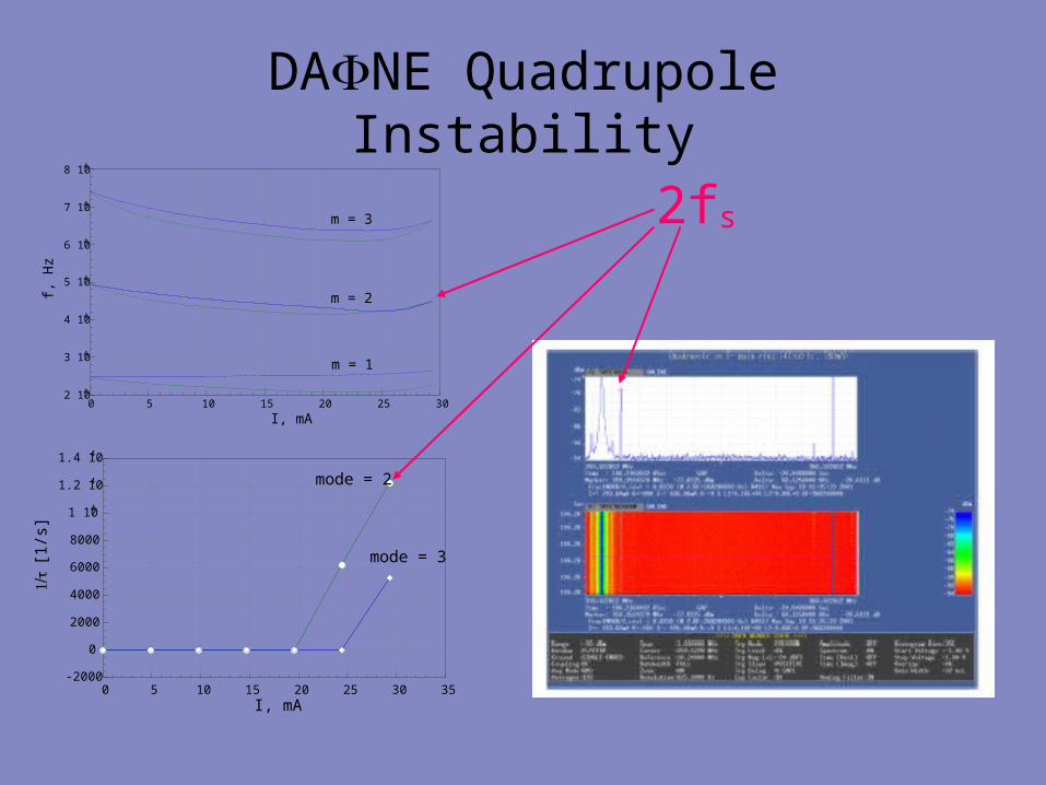
DANE Quadrupole Instability
2 104
3 104
4 104
5 104
6 104
7 104
8 104
0 5 10 15 20 25 30
f, H
z
I, mA
m = 3
m = 2
m = 1
-2000
0
2000
4000
6000
8000
1 104
1.2 104
1.4 104
0 5 10 15 20 25 30 35I, mA
[1/s
]
mode = 2
mode = 3
2fs

Bunch Lengthening in DANE Accumulator Ring
(Nucl. Instrum. Meth. A418: 241-248, 1998)
0
100
200
300
400
500
600
0 20 40 60 80 100 120
70
5555
5560
72 85
9090
I [mA]
FWHM [ps]
0
100
200
300
400
500
600
0 10 20 30 40 50 60
FWHM [ps]
I [mA]
-3 1013
-2 1013
-1 1013
0
1 1013
0 0.1 0.2 0.3 0.4 0.5
W [V/C]
z [m]
0
1
2
3
4
5
0 1 2 3 4 5f [GHz]
Z/n
Im{Z/n}Re{Z/n}
|Z/n|
Wake potential Broad-band
Impedance
Bunch Length & VRF Bunch Length & I

ATF damping ringATF damping ring
Important components to ring impedance (E-U Kim)
Wake of 6.8 mm Gaussian bunch (E-U Kim)
Energy spread for V= 300 kV
• When beam is on coupling resonanceE does not increase with current
• Fit bunch length measurements to Haissinski solution of R+L in series (done successfully at CESR)

Haissinski solution of series R+L impedance. Shown are bunch shape and induced voltage (left) and rms and centroid of shape (right); r (l) is normalized R (L) times current.
Sample measurements with fits
Summary of fits

Fitting summary
Overall: R= 1.25±.35 k L= 44.5±7.5 nH
(Impedance calculations: R= 100 L= 15 nH )
• Measurement repeated 6 months later with slightly different analysis, getting: R= 1.65±.20 , L= 32.5±1.0 nH
• Systematic errors in streak camera?
•synchroscan streak camera to measure centroid shift

Programs assessmentPrograms assessment
Wake calculation:
-as rings become cleaner 3d objects become more important; for short bunch, wakes of long 3d objects become difficult to calculate
-short Gaussian bunch filters out high frequencies; what if instability is driven at very high frequencies (e.g. CSR, microbunching)
-for short bunch (or microbunch) interaction can occur over long distances (catch-up problem)
-short bunch, long structure, small features: difficult to calculate; numerical noise
=> improved algorithms: A. Novokhatski (2d m=0), I. Zagorodnov and T. Weiland (2d m>0 and 3d)

Simulation of wake per period generated by a bunch in a tube with N small corrugations (A. Novokhatski).

Vlasov equation program:
-Oide turned the linearized Vlasov equation into a linear eigenvalue problem; many superfluous stable modes (artifact). Program does not always work.
=>R. Warnock, M. Venturini, G. Stupakov turned the linearized Vlasov equation into a non-linear eigenvalue problem; no superfluous modes. More likely to work for difficult wakes, though does not always work.
Phase space tracking:
-tracking above threshold can yield large fluctuations.
=>R. Warnock and J. Ellison have a program that solves the Vlasov-Fokker-Planck equation (VFP); more accurate than simple tracking; can e.g. solve CSR driven microbunching instability; can be time consuming.

Experimental oscilloscope traces(B. Podobedov).
Simulated oscilloscope trace using thenew SLC DR wake and the VFP program. N= 3e10. (Warnock and Ellison)
Rms energy spread just above threshold (a) and at 2e10 (b) as obtained by tracking with 30,000 macroparticles.
New SLC damping ring


![Supplement to Jamieson's Scottish dictionary with … · REE [201] REL REEL-BANE,Eeele-bane,Eewel-bane, Royal-bane,s. Anunknownmaterialof whichsaddlesweresupposedtobemade. Thistermoccursfrequently,andundervarious](https://img.pdfslide.us/doc/110x75/5b9b1d3909d3f22d2a8ca0f9/supplement-to-jamiesons-scottish-dictionary-with-ree-201-rel-reel-baneeeele-baneeewel-bane.jpg)