Embed Size (px)
Citation preview
IMPEDANCE ANALYZERComponent measuring instruments
IM3570
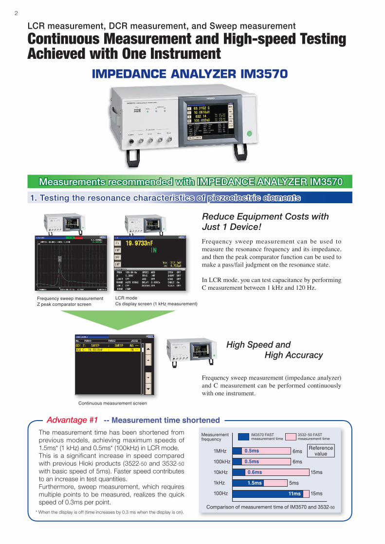
With this new IM3570 Impedance Analyzer, an LCR meter and an impedance analyzer capable of measurement frequencies of 4 Hz to 5 MHz and test signal levels of 5 mV to 5 V have been combined into one measuring instrument. Advanced capabilities include LCR measurement with AC signals, resistance measurement with direct current (DCR), and sweep measurement which continuously changes the measurement frequency and measurement level.The IM3570 facilitates high-speed continuous measurement under different measurement conditions and measurement modes, so inspection lines which up to now have required multiple measuring instruments can be equipped with just one device.
Single Device Solution for High Speed Testing and Frequency Sweeping
2
Measurements recommended with IMPEDANCE ANALYZER IM3570
LCR measurement, DCR measurement, and Sweep measurement
1. Testing the resonance characteristics of piezoelectric elements
Frequency sweep measurement can be used to measure the resonance frequency and its impedance, and then the peak comparator function can be used to make a pass/fail judgment on the resonance state.
In LCR mode, you can test capacitance by performing C measurement between 1 kHz and 120 Hz.
Frequency sweep measurement (impedance analyzer) and C measurement can be performed continuously with one instrument.
High Speed and High Accuracy
Reduce Equipment Costs with Just 1 Device!
Continuous measurement screen
IMPEDANCE ANALYZER IM3570
Advantage #1 -- Measurement time shortenedThe measurement time has been shortened from previous models, achieving maximum speeds of 1.5ms* (1 kHz) and 0.5ms* (100kHz) in LCR mode.This is a significant increase in speed compared with previous Hioki products (3522-50 and 3532-50 with basic speed of 5ms). Faster speed contributes to an increase in test quantities.Furthermore, sweep measurement, which requires multiple points to be measured, realizes the quick speed of 0.3ms per point.
* When the display is off (time increases by 0.3 ms when the display is on).
Reference value
Continuous Measurement and High-speed Testing Achieved with One Instrument
Measurement frequency
1MHz
100kHz
10kHz
1kHz
100Hz
IM3570 FAST measurement time
3532-50 FAST measurement time
Comparison of measurement time of IM3570 and 3532-50
11ms
1.5ms
0.6ms
0.5ms
0.5ms 6ms
6ms
15ms
5ms
15ms
Frequency sweep measurementZ peak comparator screen
LCR modeCs display screen (1 kHz measurement)
3
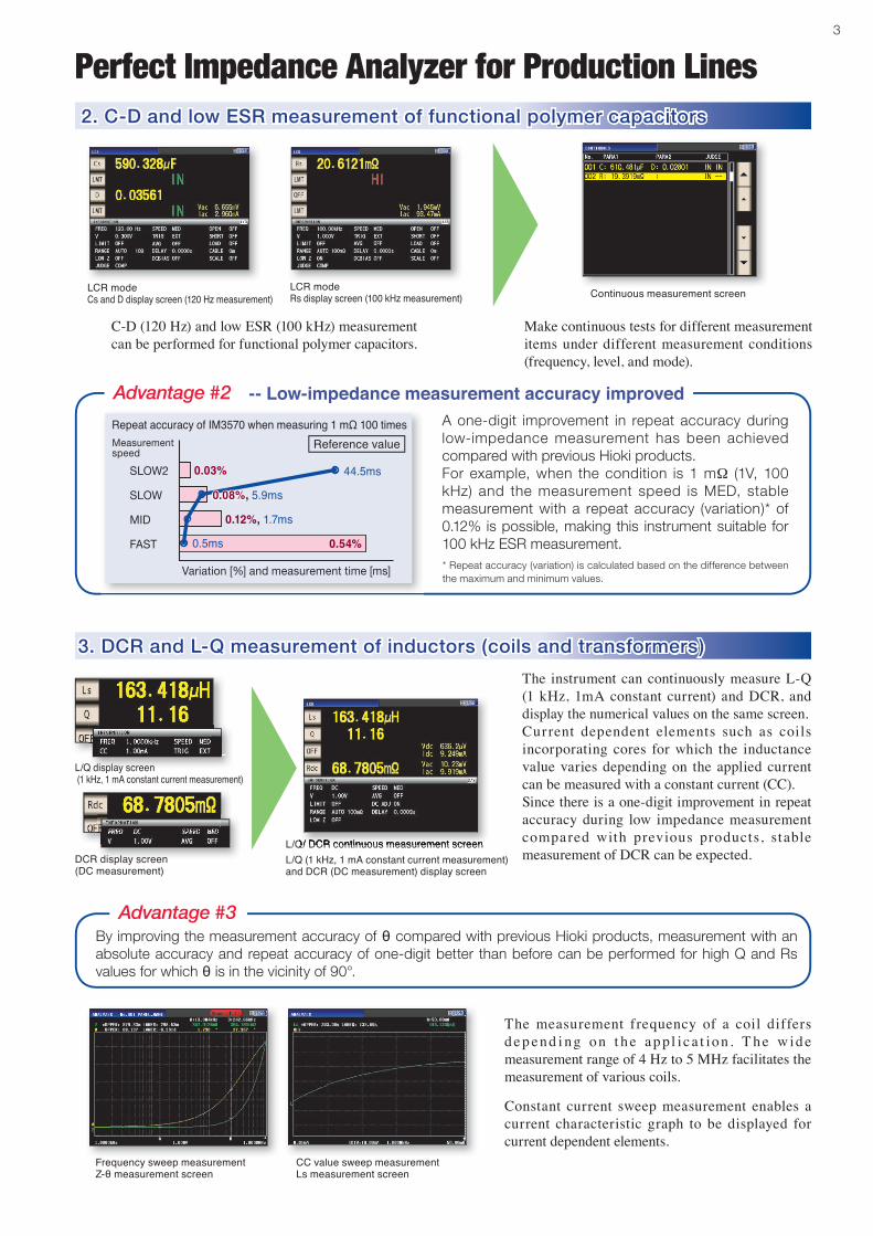
Perfect Impedance Analyzer for Production Lines2. C-D and low ESR measurement of functional polymer capacitors
3. DCR and L-Q measurement of inductors (coils and transformers)
C-D (120 Hz) and low ESR (100 kHz) measurement can be performed for functional polymer capacitors.
The instrument can continuously measure L-Q (1 kHz, 1mA constant current) and DCR, and display the numerical values on the same screen.Current dependent elements such as coils incorporating cores for which the inductance value varies depending on the applied current can be measured with a constant current (CC).Since there is a one-digit improvement in repeat accuracy during low impedance measurement compared with previous products, stable measurement of DCR can be expected.
The measurement frequency of a coil differs d ep end i ng on t he ap pl i c a t ion. T he w id e measurement range of 4 Hz to 5 MHz facilitates the measurement of various coils.
Constant current sweep measurement enables a current characteristic graph to be displayed for current dependent elements.
Make continuous tests for different measurement items under different measurement conditions (frequency, level, and mode).
Advantage #3By improving the measurement accuracy of θ compared with previous Hioki products, measurement with an absolute accuracy and repeat accuracy of one-digit better than before can be performed for high Q and Rs values for which θ is in the vicinity of 90°.
LCR modeCs and D display screen (120 Hz measurement)
LCR modeRs display screen (100 kHz measurement) Continuous measurement screen
L/Q/ DCR continuous measurement screenL/Q/ DCR continuous measurement screenDCR display screen (DC measurement)
L/Q display screen (1 kHz, 1 mA constant current measurement)
Advantage #2
Repeat accuracy of IM3570 when measuring 1 mΩ 100 times A one-digit improvement in repeat accuracy during low-impedance measurement has been achieved compared with previous Hioki products.For example, when the condition is 1 mΩ (1V, 100 kHz) and the measurement speed is MED, stable measurement with a repeat accuracy (variation)* of 0.12% is possible, making this instrument suitable for 100 kHz ESR measurement.* Repeat accuracy (variation) is calculated based on the difference between the maximum and minimum values.
-- Low-impedance measurement accuracy improved
Reference value
L/Q (1 kHz, 1 mA constant current measurement) and DCR (DC measurement) display screen
Variation [%] and measurement time [ms]
Measurement speed
SLOW2
SLOW
MID
FAST
0.03%
0.54%0.5ms
0.12%, 1.7ms
0.08%, 5.9ms
44.5ms
Frequency sweep measurementZ-θ measurement screen
CC value sweep measurementLs measurement screen
4
Test Efficiency Improved by High-speed and High-accuracy Measurements
Features of IM3570
Repeat accuracy of IM3570 when measuring 1 pF (1 MHz, 1 V) 100 times
Reference value
Interval setting screen
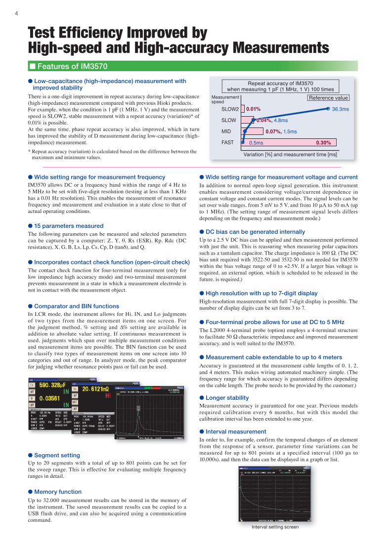
● Low-capacitance (high-impedance) measurement with improved stabilityThere is a one-digit improvement in repeat accuracy during low-capacitance (high-impedance) measurement compared with previous Hioki products.For example, when the condition is 1 pF (1 MHz, 1 V) and the measurement speed is SLOW2, stable measurement with a repeat accuracy (variation)* of 0.01% is possible.At the same time, phase repeat accuracy is also improved, which in turn has improved the stability of D measurement during low-capacitance (high-impedance) measurement.* Repeat accuracy (variation) is calculated based on the difference between the maximum and minimum values.
● Wide setting range for measurement frequencyIM3570 allows DC or a frequency band within the range of 4 Hz to 5 MHz to be set with five-digit resolution (testing at less than 1 KHz has a 0.01 Hz resolution). This enables the measurement of resonance frequency and measurement and evaluation in a state close to that of actual operating conditions.
● 15 parameters measuredThe following parameters can be measured and selected parameters can be captured by a computer: Z, Y, θ, Rs (ESR), Rp, Rdc (DC resistance), X, G, B, Ls, Lp, Cs, Cp, D (tanδ), and Q.
● Incorporates contact check function (open-circuit check)The contact check function for four-terminal measurement (only for low impedance high accuracy mode) and two-terminal measurement prevents measurement in a state in which a measurement electrode is not in contact with the measurement object.
● Memory functionUp to 32,000 measurement results can be stored in the memory of the instrument. The saved measurement results can be copied to a USB flash drive, and can also be acquired using a communication command.
● Segment settingUp to 20 segments with a total of up to 801 points can be set for the sweep range. This is effective for evaluating multiple frequency ranges in detail.
● Wide setting range for measurement voltage and currentIn addition to normal open-loop signal generation, this instrument enables measurement considering voltage/current dependence in constant voltage and constant current modes. The signal levels can be set over wide ranges, from 5 mV to 5 V, and from 10 μA to 50 mA (up to 1 MHz). (The setting range of measurement signal levels differs depending on the frequency and measurement mode.)
● DC bias can be generated internallyUp to a 2.5 V DC bias can be applied and then measurement performed with just the unit. This is reassuring when measuring polar capacitors such as a tantalum capacitor. The charge impedance is 100 Ω. (The DC bias unit required with 3522-50 and 3532-50 is not needed for IM3570 within the bias voltage range of 0 to +2.5V. If a larger bias voltage is required, an external option, which is scheduled to be released in the future, is required.)
● High resolution with up to 7-digit displayHigh-resolution measurement with full 7-digit display is possible. The number of display digits can be set from 3 to 7.
● Four-terminal probe allows for use at DC to 5 MHzThe L2000 4-terminal probe (option) employs a 4-terminal structure to facilitate 50 Ω characteristic impedance and improved measurement accuracy, and is well suited to the IM3570.
● Measurement cable extendable to up to 4 metersAccuracy is guaranteed at the measurement cable lengths of 0, 1, 2, and 4 meters. This makes wiring automated machinery simple. (The frequency range for which accuracy is guaranteed differs depending on the cable length. The probe needs to be provided by the customer.)
● Longer stabilityMeasurement accuracy is guaranteed for one year. Previous models required calibration every 6 months, but with this model the calibration interval has been extended to one year.
● Interval measurementIn order to, for example, confirm the temporal changes of an element from the response of a sensor, parameter time variations can be measured for up to 801 points at a specified interval (100 μs to 10,000s), and then the data can be displayed in a graph or list.
Measurement speed
Variation [%] and measurement time [ms]
SLOW2
SLOW
MID
FAST 0.5ms 0.30%
0.07%, 1.5ms
0.04%, 4.8ms
0.01% 36.3ms
In LCR mode, the instrument allows for Hi, IN, and Lo judgments of two types from the measurement items on one screen. For the judgment method, % setting and ∆% setting are available in addition to absolute value setting. If continuous measurement is used, judgments which span over multiple measurement conditions and measurement items are possible. The BIN function can be used to classify two types of measurement items on one screen into 10 categories and out of range. In analyzer mode, the peak comparator for judging whether resonance points pass or fail can be used.
● Comparator and BIN functions
5
Measurement results and settings can be saved to a commercially available USB flash drive connected to the front panel.
Saving and reading data via front-loading USB port
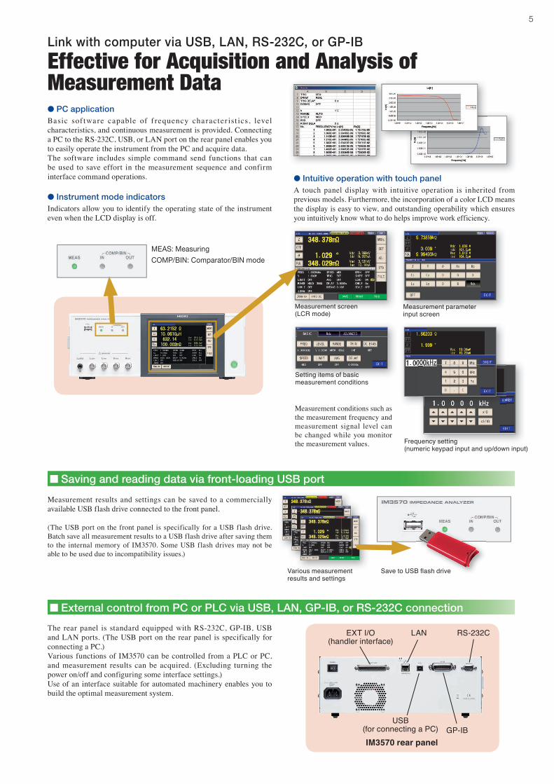
Measurement conditions such as the measurement frequency and measurement signal level can be changed while you monitor the measurement values.
Setting items of basic measurement conditions
Frequency setting (numeric keypad input and up/down input)
Measurement parameterinput screen
Measurement screen(LCR mode)
The rear panel is standard equipped with RS-232C, GP-IB, USB and LAN ports. (The USB port on the rear panel is specifically for connecting a PC.)Various functions of IM3570 can be controlled from a PLC or PC, and measurement results can be acquired. (Excluding turning the power on/off and configuring some interface settings.)Use of an interface suitable for automated machinery enables you to build the optimal measurement system.
External control from PC or PLC via USB, LAN, GP-IB, or RS-232C connection
IM3570 rear panel
LAN RS-232C
● DC bias can be generated internally
● High resolution with up to 7-digit display
● Four-terminal probe allows for use at DC to 5 MHz
● Interval measurement
Link with computer via USB, LAN, RS-232C, or GP-IB
Effective for Acquisition and Analysis of Measurement Data● PC applicationBasic sof tware capable of f requency character ist ics, level characteristics, and continuous measurement is provided. Connecting a PC to the RS-232C, USB, or LAN port on the rear panel enables you to easily operate the instrument from the PC and acquire data.The software includes simple command send functions that can be used to save effort in the measurement sequence and confirm interface command operations.
MEAS: Measuring
COMP/BIN: Comparator/BIN mode
● Intuitive operation with touch panelA touch panel display with intuitive operation is inherited from previous models. Furthermore, the incorporation of a color LCD means the display is easy to view, and outstanding operability which ensures you intuitively know what to do helps improve work efficiency.
(The USB port on the front panel is specifically for a USB flash drive. Batch save all measurement results to a USB flash drive after saving them to the internal memory of IM3570. Some USB flash drives may not be able to be used due to incompatibility issues.)
Various measurement results and settings
Save to USB flash drive
EXT I/O(handler interface)
GP-IBUSB
(for connecting a PC)
● Instrument mode indicatorsIndicators allow you to identify the operating state of the instrument even when the LCD display is off.
6
EXT I/O
IM3570 specifications
Measurement modes
LCR mode: Measurement with single conditionAnalyzer mode: Sweeps with measurement frequency and measurement level(Measurement points: 1 to 801, Measurement method: normal sweep or segment sweep, Display: List display or graph display)Continuous measurement mode: Measures under saved conditions continuously (maximum of 32 sets)
Measurement parameters
Z ImpedanceY Admittance θ Phase angleRs(ESR) Series-equivalent resistance = ESRRp Parallel-equivalent resistanceRdc DC resistanceX ReactanceG ConductanceB SusceptanceCs Series-equivalent static capacitanceCp Parallel-equivalent static capacitanceLs Series-equivalent inductanceLp Parallel-equivalent inductanceD(tanδ) Loss coefficient = tan δ (δ= delta)Q Q factor (Q = 1/D)
Measurement range
100 mΩ to 100 MΩ, 12 ranges(All parameters are determined according to Z )
Display range
Z, Y, Rs, Rp, Rdc, X, G, B, Ls, Lp, Cs, Cp : ±(0.000000 [unit] to 9.999999G [unit]
Absolute value display for Z and Y only θ : ±(0.000° to 999.999°)D : ±(0.000000 to 9.999999) Q : ±(0.00 to 99999.99) Δ % : ±(0.0000% to 999.9999%)
Basic accuracy Z : ±0.08%rdg. θ: ±0.05° Measurement frequency 4Hz to 5MHz (10 mHz to 100 Hz steps)
Measurement signal level
Normal mode:V mode/CV mode: 5 mV to 5 Vrms (up to 1 MHz),10 mV to 1 Vrms (1 MHz to 5 MHz), 1 mVrms stepsCC mode: 10 μA to 50 mArms (up to 1 MHz),10 μA to 10 mArms (1 MHz to 5 MHz), 10 μArms steps
Low impedance high accuracy mode:V mode/CV mode: 5 mV to 1 Vrms (up to 100 kHz), 1 mVrms stepsCC mode:10 μA to 100 mArms (100 mΩ and 1Ω
ranges of up to 100 kHz), 10 μArms steps
Output impedance
Normal mode: 100 ΩLow impedance high accuracy mode: 10 Ω
Display 5.7-inch color TFT, display can be set to ON/OFFNo. of display digits setting
The number of display digits can be set from 3 to 7(initial value: 6 digits)
Measurement time 0.5 ms (100 kHz, FAST, display OFF, representative value)Measurement speed FAST/MED/SLOW/SLOW2
DC bias measurement
Normal mode: 0 VDC to 2.50 VDC (10 mV steps)Low impedance high accuracy mode:0 VDC to 1.00 VDC (10 mV steps)
DC resistance measurement
Normal modeMeasurement signal level: 100 mVDC to 2.5 VDC (10 mV steps)Low impedance high accuracy modeMeasurement signal level: 100 mVDC to 1.00 VDC (10 mV steps)
Comparator
LCR mode: Hi/IN/Lo for first and third itemsAnalyzer mode: Area judgment (Hi/IN/Lo for each point) Peak judgment (Hi/IN/Lo for local maximum and local minimum frequency and absolute values)
BIN measurement 10 classifications and out of range for 2 items
Compensation Open/short/load/cable length of 0 and 1 m/correlation compensation
Residual charge protection function
V= (C: Capacitance [F] of test sample, V = max. 400 V)
Trigger synchronous output function
Applies a measurement signal during analog measurement only
Averaging 1 to 256Interval measurement 100 μs to 10,000 s, max. 801 pointsPanel loading/saving LCR mode: 30; Analyzer mode: 2; Compensation value: 128Memory function Stores 32,000 data items to the memory of the instrument
Interfaces EXT I/O (handler), RS-232C, GP-IB, USB (Hi-Speed/Full-Speed), USB flash drive, LAN (10BASE-T/100BASE-TX)
Operating temperature and humidity ranges
0°C to 40°C, 80% RH or less, no condensation
Storage temperature and humidity ranges
-10°C to 50°C, 80% RH or less, no condensation
Power supply 90 to 264 V AC, 50/60 Hz, 150 VA max.Dimensions and weight Approx. 330 (W) x 119 (H) x 307 (D), approx. 5.8 kg
Accessory Power cord x 1
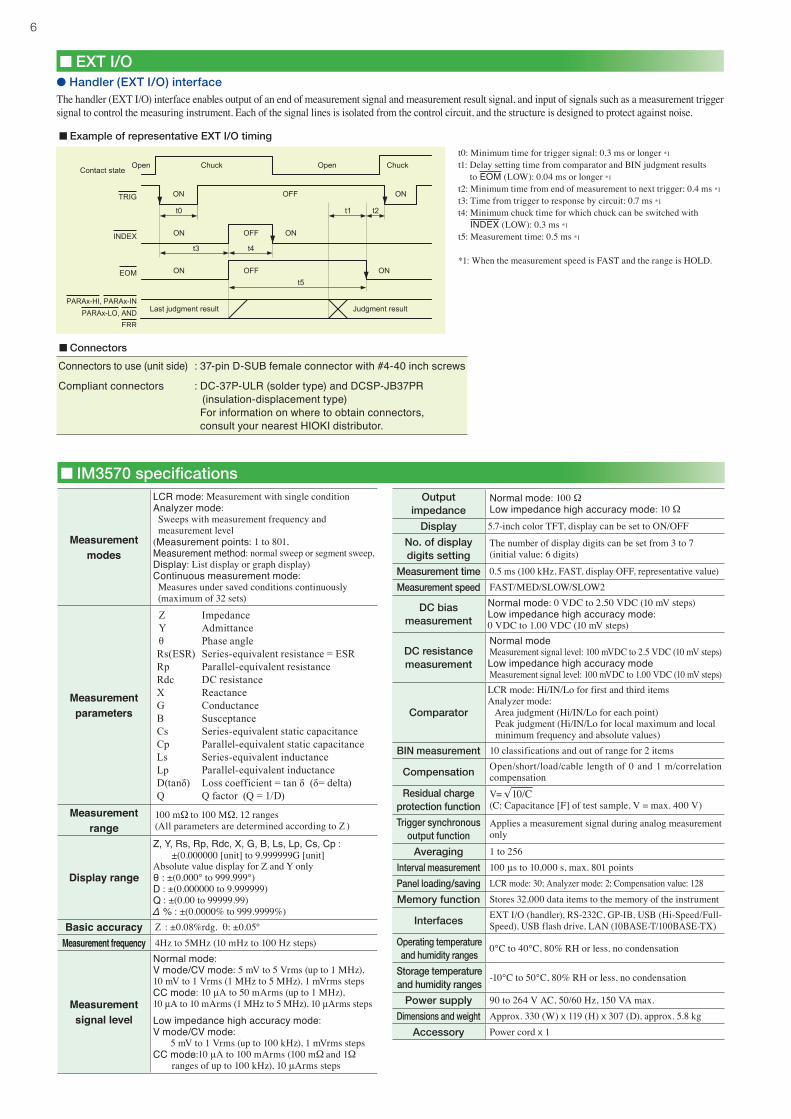
● Handler (EXT I/O) interfaceThe handler (EXT I/O) interface enables output of an end of measurement signal and measurement result signal, and input of signals such as a measurement trigger signal to control the measuring instrument. Each of the signal lines is isolated from the control circuit, and the structure is designed to protect against noise.
Example of representative EXT I/O timing
Connectors
Connectors to use (unit side)
Compliant connectors
: 37-pin D-SUB female connector with #4-40 inch screws
: DC-37P-ULR (solder type) and DCSP-JB37PR (insulation-displacement type)
For information on where to obtain connectors, consult your nearest HIOKI distributor.
t0: Minimum time for trigger signal: 0.3 ms or longer *1
t1: Delay setting time from comparator and BIN judgment results to EOM (LOW): 0.04 ms or longer *1
t2: Minimum time from end of measurement to next trigger: 0.4 ms *1
t3: Time from trigger to response by circuit: 0.7 ms *1
t4: Minimum chuck time for which chuck can be switched with INDEX (LOW): 0.3 ms *1
t5: Measurement time: 0.5 ms *1
*1: When the measurement speed is FAST and the range is HOLD.
√ 10/C
7
ConditionsTemperature and humidity ranges: 23℃ ± 5℃, 80% RH or less (no condensation), at least 60 minutes after power turned on, after performing open and short compensation
Basic accuracy
Range Guaranteed accuracy range DC 4 Hz to 99.9 Hz 100 Hz to 999.99 Hz 1 kHz to 10 kHz 10.01 kHz to 100 kHz 100.1 kHz to 1 MHz 1.001 MHz to 5 MHz
100MΩ 8MΩ to 200MΩ A=4 B=6 A=6 B=5A=5 B=3
A=3 B=2A=2 B=2
A=3 B=2A=2 B=2
A=8 B=4A=3 B=2
10MΩ 800kΩ to 100MΩ A=0.5 B=0.3 A=0.8 B=1A=0.8 B=0.5
A=0.5 B=0.3A=0.4 B=0.2
A=0.5 B=0.3A=0.4 B=0.2
A=1 B=0.7A=1 B=0.2
A=3 B=2A=3 B=1
1MΩ 80kΩ to 10MΩ A=0.2 B=0.1 A=0.4 B=0.08A=0.3 B=0.08
A=0.3 B=0.05A=0.2 B=0.02
A=0.3 B=0.05A=0.2 B=0.02
A=0.3 B=0.08A=0.3 B=0.08
A=1 B=0.5A=1 B=0.5
* A=2 B=1 A=2 B=1
100kΩ 24kΩ to 1MΩ A=0.1 B=0.01 A=0.3 B=0.01A=0.3 B=0.01
A=0.2 B=0.01A=0.1 B=0.01
A=0.15 B=0.01A=0.1 B=0.01
A=0.25 B=0.04A=0.2 B=0.02
A=0.4 B=0.3A=0.3 B=0.3
* A=2 B=0.5 A=2 B=0.3
30kΩ 8kΩ to 300kΩ A=0.1 B=0.01 A=0.3 B=0.01A=0.3 B=0.01
A=0.2 B=0.005A=0.1 B=0.003
A=0.12 B=0.005A=0.08 B=0.003
A=0.25 B=0.01A=0.15 B=0.005
A=0.4 B=0.05A=0.3 B=0.03
* A=2 B=0.1 A=2 B=0.1
10kΩ 2.4kΩ to 100kΩ A=0.1 B=0.01 A=0.3 B=0.01A=0.3 B=0.01
A=0.2 B=0.01A=0.1 B=0.005
A=0.12 B=0.005A=0.08 B=0.002
A=0.2 B=0.02A=0.08 B=0.02
A=0.3 B=0.03A=0.2 B=0.05
* A=1.5 B=0.2 A=1 B=0.2
3kΩ 800Ω to 30kΩ A=0.1 B=0.01 A=0.3 B=0.02A=0.2 B=0.01
A=0.2 B=0.005A=0.1 B=0.002
A=0.12 B=0.005A=0.08 B=0.002
A=0.2 B=0.005A=0.08 B=0.005
A=0.3 B=0.01A=0.15 B=0.01
* A=1.5 B=0.02 A=1 B=0.03
1kΩ 240Ω to 10kΩ A=0.1 B=0.01 A=0.3 B=0.02A=0.2 B=0.01
A=0.2 B=0.01A=0.1 B=0.005
A=0.1 B=0.005A=0.08 B=0.002
A=0.2 B=0.01A=0.08 B=0.01
A=0.3 B=0.01A=0.15 B=0.01
* A=1.5 B=0.01 A=1 B=0.01
300Ω 8Ω to 300Ω A=0.1 B=0.02 A=0.4 B=0.02A=0.2 B=0.01
A=0.3 B=0.02A=0.15 B=0.01
A=0.08 B=0.02A=0.05 B=0.01
A=0.2 B=0.02A=0.08 B=0.02
A=0.3 B=0.03A=0.15 B=0.02
* A=1.5 B=0.05 A=1 B=0.05
10Ω 800mΩ to 10Ω A=0.2 B=0.15 A=0.5 B=0.2A=0.3 B=0.1
A=0.4 B=0.05A=0.3 B=0.03
A=0.3 B=0.05A=0.15 B=0.03
A=0.3 B=0.05A=0.15 B=0.03
A=0.4 B=0.2A=0.3 B=0.1
* A=2 B=1.5 A=2 B=1
1Ω 80mΩ to 1Ω A=0.3 B=0.3 A=2 B=1A=1 B=0.6
A=0.6 B=0.3A=0.5 B=0.2
A=0.4 B=0.3A=0.25 B=0.2
A=0.4 B=0.3A=0.25 B=0.2
A=1 B=1A=0.7 B=0.5
* A=3 B=3 A=3 B=2
100mΩ 1mΩ to 100mΩ A=3 B=2 A=10 B=10A=6 B=6
A=3 B=3A=2 B=2
A=3 B=3A=2 B=1.5
A=2 B=2A=2 B=1.5
A=4 B=3A=3 B=4
Zx is the actual impedance measurement value (Z) of the sample.
Bottom A: Basic accuracy of θ (± % deg.)B is the coefficient for the impedance of the sample
A is the accuracy of R when DC (± % rdg.)B is the coefficient for the resistance of the sample
Top A: Basic accuracy of Z (± % rdg.)B is the coefficient for the impedance of the sample
In the 1 kΩ range and above and 300 Ω range and below, the calculation expression of basic accuracy differs as shown below. For details, refer to the following calculation examples.
Basic accuracy (Z, θ) calculation expression
1 kΩ range and above:
300 Ω range and below:
[C: Level coefficient]
● Calculation exampleImpedance Zx of sample: 500 Ω (actual measurement value)Measurement conditions: When frequency 10 kHz and range 1 kΩ
Insert coefficient A = 0.1 and coefficient B = 0.005 for the Z basic accuracy from the table above into the expression.
IM3570 measurement accuracy
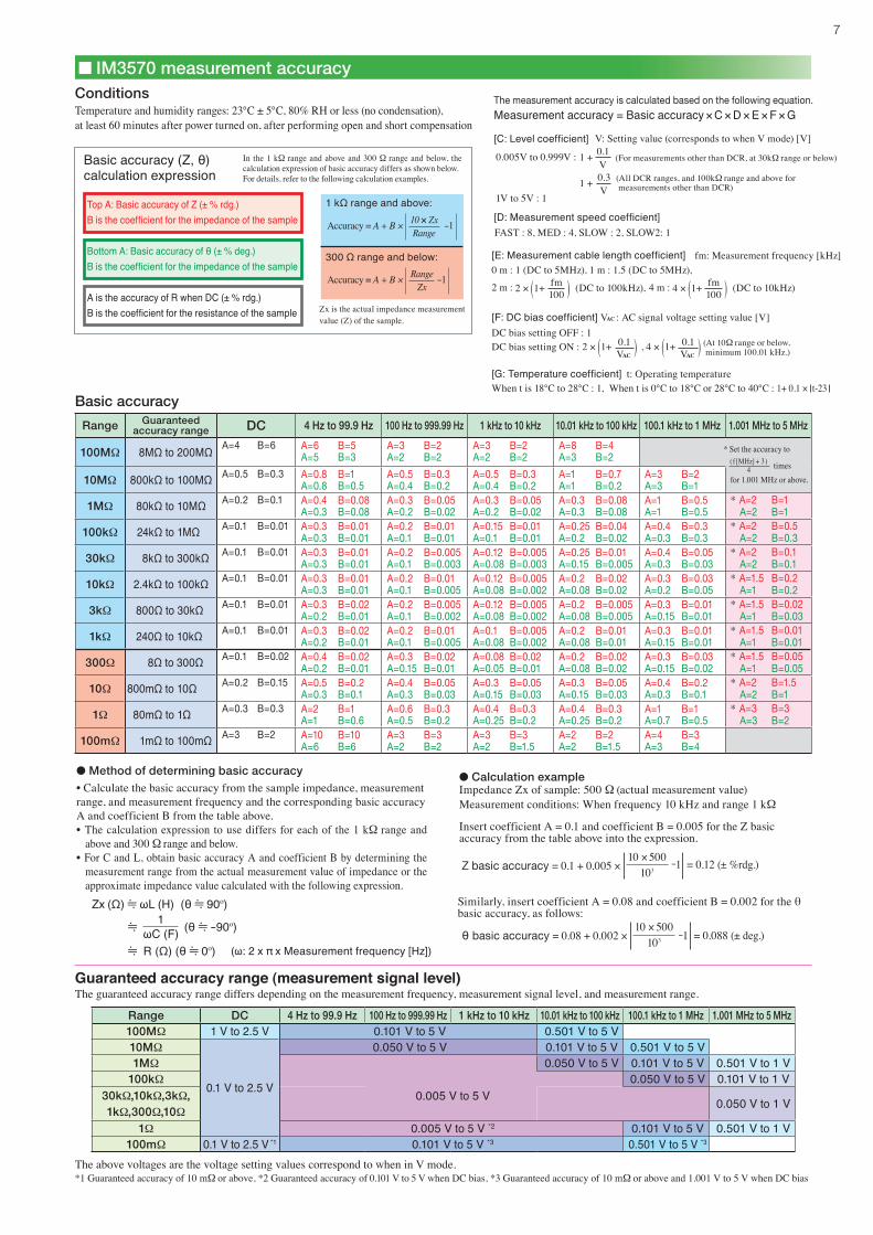
Range DC 4 Hz to 99.9 Hz 100 Hz to 999.99 Hz 1 kHz to 10 kHz 10.01 kHz to 100 kHz 100.1 kHz to 1 MHz 1.001 MHz to 5 MHz100MΩ 1 V to 2.5 V 0.101 V to 5 V 0.501 V to 5 V10MΩ
0.1 V to 2.5 V
0.050 V to 5 V 0.101 V to 5 V 0.501 V to 5 V1MΩ 0.050 V to 5 V 0.101 V to 5 V 0.501 V to 1 V
100kΩ0.005 V to 5 V
0.050 V to 5 V 0.101 V to 1 V30kΩ,10kΩ,3kΩ,1kΩ,300Ω,10Ω
0.050 V to 1 V
1Ω 0.005 V to 5 V *2 0.101 V to 5 V 0.501 V to 1 V100mΩ 0.1 V to 2.5 V *1 0.101 V to 5 V *3 0.501 V to 5 V *3
Guaranteed accuracy range (measurement signal level)The guaranteed accuracy range differs depending on the measurement frequency, measurement signal level, and measurement range.
The above voltages are the voltage setting values correspond to when in V mode.*1 Guaranteed accuracy of 10 mΩ or above, *2 Guaranteed accuracy of 0.101 V to 5 V when DC bias, *3 Guaranteed accuracy of 10 mΩ or above and 1.001 V to 5 V when DC bias
● Method of determining basic accuracy• Calculate the basic accuracy from the sample impedance, measurement range, and measurement frequency and the corresponding basic accuracy A and coefficient B from the table above.• The calculation expression to use differs for each of the 1 kΩ range and
above and 300 Ω range and below.• For C and L, obtain basic accuracy A and coefficient B by determining the
measurement range from the actual measurement value of impedance or the approximate impedance value calculated with the following expression.
Accuracy = A + B × 10 × ZxRange
-1
Accuracy = A + B × RangeZx
-1
The measurement accuracy is calculated based on the following equation.
Measurement accuracy = Basic accuracy × C × D × E × F × G
0.005V to 0.999V :
1V to 5V : 1
[D: Measurement speed coefficient]
[F: DC bias coefficient] VAC : AC signal voltage setting value [V]DC bias setting OFF : 1
[G: Temperature coefficient] t: Operating temperatureWhen t is 18℃ to 28℃ : 1, When t is 0℃ to 18℃ or 28℃ to 40℃ : 1+ 0.1 × t-23
V: Setting value (corresponds to when V mode) [V]
FAST : 8, MED : 4, SLOW : 2, SLOW2: 1
0 m : 1 (DC to 5MHz), 1 m : 1.5 (DC to 5MHz),
* Set the accuracy to( f [MHz] + 3 )
4 times for 1.001 MHz or above.
(ω: 2 x π x Measurement frequency [Hz]) R (Ω) (θ 0º)
Zx (Ω) ωL (H) (θ 90º)
(θ -90º)1ωC (F)
Z basic accuracy = 0.1 + 0.005 × -1 = 0.12 (± %rdg.)103
10 × 500
Similarly, insert coefficient A = 0.08 and coefficient B = 0.002 for the θ basic accuracy, as follows:
θ basic accuracy = 0.08 + 0.002 × -1 = 0.088 (± deg.)103
10 × 500
[E: Measurement cable length coefficient] fm: Measurement frequency [kHz]
1 +V0.1
(For measurements other than DCR, at 30kΩ range or below)
1 +V0.3 (All DCR ranges, and 100kΩ range and above for
measurements other than DCR)
100fm( )2 × 1+2 m : (DC to 100kHz), 100
fm( )4 × 1+4 m : (DC to 10kHz)
( )2 × 1+VAC
0.1 ( ), 4 × 1+VAC
0.1 (At 10Ω range or below, minimum 100.01 kHz.)DC bias setting ON :
Headquarters :81 Koizumi, Ueda, Nagano, 386-1192, JapanTEL +81-268-28-0562 / FAX +81-268-28-0568 http://www.hioki.co.jp / E-mail: [email protected]
HIOKI USA CORPORATION :6 Corporate Drive, Cranbury, NJ 08512 USATEL +1-609-409-9109 / FAX +1-609-409-9108http://www.hiokiusa.com / E-mail: [email protected]
All information correct as of Sep. 26, 2011. All specifi cations are subject to change without notice. IM3570E3-19E
DISTRIBUTED BYHIOKI (Shanghai) Sales & Trading Co., Ltd. :1608-1610,Shanghai Times Square Offi ce, 93 Huai Hai Zhong RoadShanghai, P.R.China POSTCODE: 200021TEL +86-21-63910090/63910092 FAX +86-21-63910360http://www.hioki.cn / E-mail: [email protected] Offi ce : TEL +86-10-84418761 / 84418762Guangzhou Offi ce : TEL +86-20-38392673 / 38392676HIOKI INDIA PRIVATE LIMITED :Khandela House, 24 Gulmohar Colony Indore 452 018 (M.P.), IndiaTEL +91-731-4223901, 4223902 FAX +91-731-4223903http://www.hioki.in / E-mail: [email protected] SINGAPORE PTE. LTD. :33 Ubi Avenue 3, #03-02 Vertex, Singapore 408868TEL +65-6634-7677 FAX +65-6634-7477E-mail: [email protected]
Note: Company names and Product names appearing in this catalog are trademarks or registered trademarks of various companies.
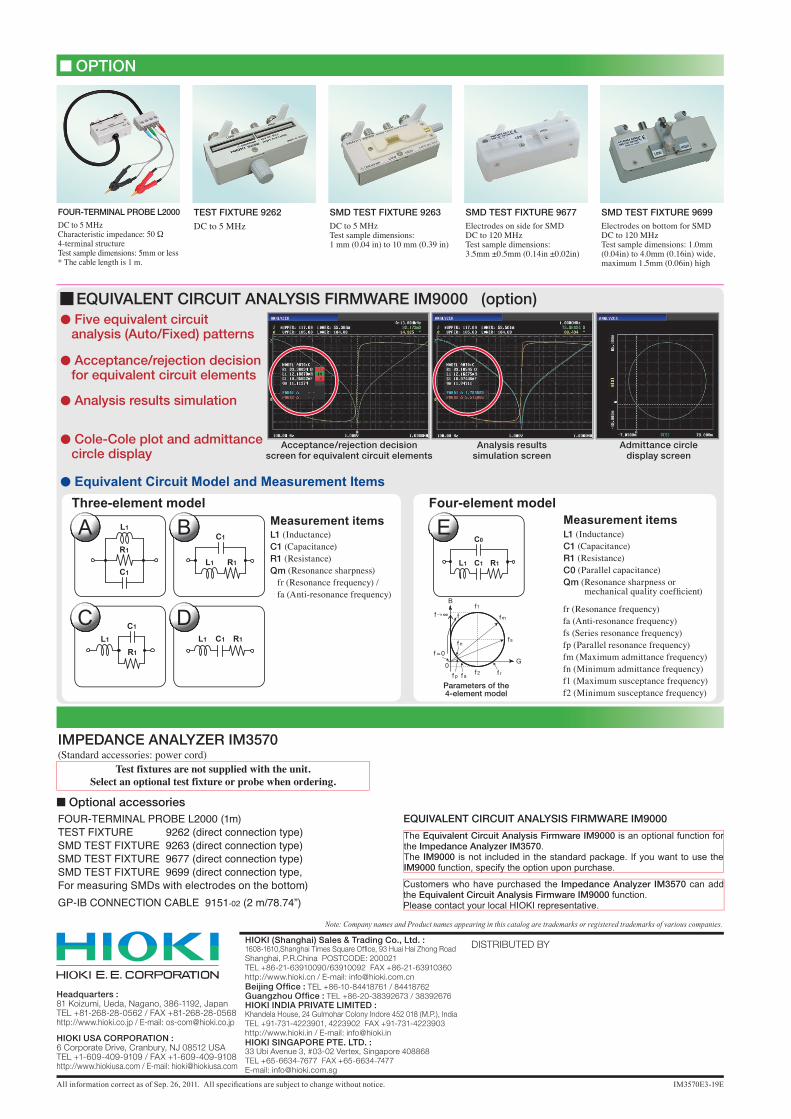
IMPEDANCE ANALYZER IM3570(Standard accessories: power cord)
Test fixtures are not supplied with the unit. Select an optional test fixture or probe when ordering.
FOUR-TERMINAL PROBE L2000 (1m)TEST FIXTURE 9262 (direct connection type)SMD TEST FIXTURE 9263 (direct connection type) SMD TEST FIXTURE 9677 (direct connection type)SMD TEST FIXTURE 9699 (direct connection type, For measuring SMDs with electrodes on the bottom)GP-IB CONNECTION CABLE 9151-02 (2 m/78.74”)
OPTION
■ Optional accessories
SMD TEST FIXTURE 9677Electrodes on side for SMDDC to 120 MHzTest sample dimensions: 3.5mm ±0.5mm (0.14in ±0.02in)
SMD TEST FIXTURE 9699Electrodes on bottom for SMDDC to 120 MHz Test sample dimensions: 1.0mm (0.04in) to 4.0mm (0.16in) wide, maximum 1.5mm (0.06in) high
TEST FIXTURE 9262
DC to 5 MHzSMD TEST FIXTURE 9263DC to 5 MHzTest sample dimensions:1 mm (0.04 in) to 10 mm (0.39 in)
FOUR-TERMINAL PROBE L2000
DC to 5 MHzCharacteristic impedance: 50 Ω4-terminal structureTest sample dimensions: 5mm or less* The cable length is 1 m.
Acceptance/rejection decision screen for equivalent circuit elements
Analysis results simulation screen
Admittance circle display screen
EQUIVALENT CIRCUIT ANALYSIS FIRMWARE IM9000 (option)
● Acceptance/rejection decision for equivalent circuit elements
● Cole-Cole plot and admittance circle display
● Five equivalent circuit analysis (Auto/Fixed) patterns
● Analysis results simulation
● Equivalent Circuit Model and Measurement Items
Measurement itemsL1 (Inductance)C1 (Capacitance)R1 (Resistance)Qm (Resonance sharpness) fr (Resonance frequency) / fa (Anti-resonance frequency)
L1 (Inductance)C1 (Capacitance)R1 (Resistance)C0 (Parallel capacitance)Qm (Resonance sharpness or mechanical quality coeffi cient)
Measurement items
fr (Resonance frequency)fa (Anti-resonance frequency)fs (Series resonance frequency)fp (Parallel resonance frequency)fm (Maximum admittance frequency)fn (Minimum admittance frequency)f1 (Maximum susceptance frequency)f2 (Minimum susceptance frequency)
Parameters of the4-element model
Three-element model Four-element model
A E
C D
B
EQUIVALENT CIRCUIT ANALYSIS FIRMWARE IM9000
The Equivalent Circuit Analysis Firmware IM9000 is an optional function for the Impedance Analyzer IM3570. The IM9000 is not included in the standard package. If you want to use the IM9000 function, specify the option upon purchase.
Customers who have purchased the Impedance Analyzer IM3570 can add the Equivalent Circuit Analysis Firmware IM9000 function.Please contact your local HIOKI representative.