Embed Size (px)
Citation preview
AIAA JOURNAL
Vol. 40, No. 10, October 2002
Impact Response of Adaptive Piezoelectric Laminated Plates
Dimitris A. Saravanos¤
University of Patras, 265 00 Patras, Greeceand
Andreas P. Christoforou†
Kuwait University, 13060, Kuwait
Semi-analyticalmodels for the impact response of composite plates having distributed active and sensory piezo-electric layers are presented. An exact Ritz model is utilized based on a mixed-� eld piezoelectric laminate theorythat encompassesbothdisplacementand electric displacement � elds throughthe laminate.The governingequationsof motion of a simply supported plate and a low-velocity impactor are formulated including impactor dynamicsand contact law. State feedback linear quadratic regulator and output feedback controllers are implemented toactively reduce impact force. Numerical results quantify the electromechanical response of a composite plate withpiezoelectric sensors impacted by three different mass impactors. The impact response of an actively controlledplate is also shown, and the possibility to improve critical impact parameters is demonstrated.
Introduction
IMPACT is a common threat in many structuralapplicationsgen-erating large forces that can causedamage in mechanicalcompo-
nents. In composite structures even low-velocity impact events caninducehiddendamageconsistingof delaminations,matrix cracking,and � ber breakage. Such types of damage increase the safety riskand reduce the effectivenessof composite structuresas load-bearingmembers. It is very desirable, therefore, to � nd new approaches thatcan reduce the severityof impact damage and/or help in identifyingthe impact event. Adaptive piezoelectric composite laminates withembedded piezoelectricactuatorsand sensors might be good candi-dates for mitigating impact effects as well as for impact parameteridenti� cation and damage monitoring and assessment.
Althoughsubstantialeffortshavebeendirectedtowardstheanaly-sis and dynamic response of piezoelectriccomposite laminates andstructures,1;2 it seems that the impact of piezoelectric compositeplates has received little attention, mainy in impact load and loca-tion identi� cation.3 Similarly, signi� cant efforts have been reportedon active vibrationcontrolwith adaptivepiezoelectricstructures,4¡9
and yet it seems that the active control of impact has received mini-mal attention, and most of the work is mainly in the area of control-ling impact in robotic manipulators.10¡12 In robotics, however, theimpacting body is controlled, whereas in the case of structural im-pact by a foreignobject the controlactionshouldbe on the target andnot the impactor.This situationpresents a differentproblemand canpose certain challenges in controlling the impact event because keystates, such as the impact locationand impactor dynamics,might beunknown. Birman et al.13 proposed the use of shape memory alloysto reduce the de� ections and impact damage in composite plates.The results showed a signi� cant reduction in the de� ections withmoderate reduction in the stresses.
Librescu and Na14 have reported work on the active control ofthin-wall piezoelectricbeams subject to blast pulses. Both previousstudies assume prescribed impact loading. Yigit and Christoforou15
have studied the impact control of composite plates using concen-trated force actuators with an optimal state feedback strategy. Theyshowed that the control of impact might be possible, provided that
Received 24 October 2000; revision received 5 November 2001;acceptedfor publication 21 April 2002. Copyright c° 2002 by the American Insti-tute of Aeronautics and Astronautics, Inc. All rights reserved. Copies ofthis paper may be made for personal or internal use, on condition that thecopier pay the $10.00 per-copy fee to the Copyright Clearance Center, Inc.,222 Rosewood Drive, Danvers, MA 01923; include the code 0001-1452/02$10.00 in correspondence with the CCC.
¤Associate Professor, Department of Mechanical Engineering and Aero-nautics; [email protected]. Senior Member AIAA.
†Associate Professor, Department of Mechanical and Industrial Engi-neering.
all of the states are timely observed and high-speed actuators areavailable.
Consequently, the present paper investigates the possibility tocontrol impact using distributedpiezoelectricactuatorsand sensors.In this context a semi-analyticalmodel is developed for predictingthe electromechanical impact response of piezoelectric plates hav-ing distributedactive and sensory layers with and without controllerinteraction.The analyticalmodelcombineselementsof the so-calledmixed-� eld piezoelectriclaminate mechanics,16 which directly rep-resents all electromechanicalstate � elds in a piezoelectric laminateby combiningdifferentkinematicapproximationsfor each � eld, thatis, single-layer kinematic assumptions for the displacements witha layerwise variation of the electric potential. The mechanics nat-urally capture the effects of actuators and sensors. The governingequations of motion of a simply supportedplate and a low-velocityimpactor are subsequently formulated including impactor dynam-ics and contact law17 in the form of a Ritz solution procedure forpredictingthe time responseof the piezoelectricplate-impactorsys-tem using explicit numerical integration.Emphasis is placed on thedirect inclusion of impactor-targetdynamic interactionsand a real-istic nonlinear contact law into the model, whereas other nonlinearphenomena, such as damage of the piezoelectric laminate, are leftas topics of future study. State and output feedback controllers areincorporatedinto the model to assess the feasibility of actively con-trolling low-velocity impact response.
Piezoelectric Plate in ImpactThe impacted laminatedpiezoelectric-composite plate is modeled
using the mixed-� eld piezoelectric laminate theory.16 In summary,the theory combines � rst-order shear kinematic assumptions fordisplacements with layerwise approximation of electric potentialthrough the thickness of the ply. A Cartesian coordinate systemOxyz is de� ned such that the x and y axes lie on the midsurface,while the z axis is perpendicular to the plane of the laminate. Eachply is a linear piezoelectric material with constitutive equations ofthe following form:
¾i D C Ei j S j ¡ eik Ek ; Dl D el j S j C "S
lk Ek (1)
where i; j D 1; : : : ; 6 and k; l D 1; : : : ; 3; ¾i and S j are the me-chanical stresses and engineering strains in vectorial notation; Ek
is the electric � eld vector; Dl is the electric displacement vector;Ci j the elastic stiffness tensor; el j the piezoelectrictensor; and "lk isthe electric permittivity tensor of the material. Superscripts E andS indicate constant electric � eld and strain conditions,respectively.The axes 1, 2, and 3 of the material are parallel to the Cartesiancoordinate axes x , y, and z, respectively.
2087
Dow
nloa
ded
by C
AR
LE
TO
N U
NIV
ER
SIT
Y L
IBR
AR
Y o
n Ju
ly 7
, 201
4 | h
ttp://
arc.
aiaa
.org
| D
OI:
10.
2514
/2.1
543
2088 SARAVANOS AND CHRISTOFOROU
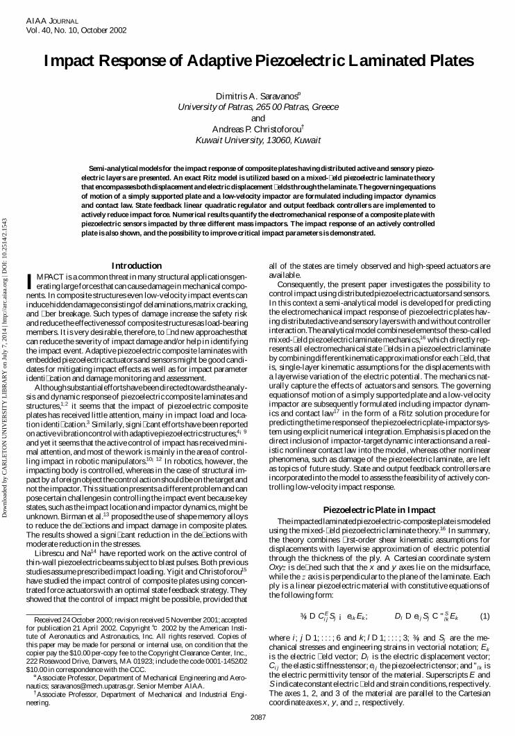
Laminate TheoryThe implemented mixed-� eld piezoelectric laminate theory16
(MPLT) utilizes both displacementsand electric potential as gener-alized state variables and combines different types of through-the-thicknessapproximationsof the state variables (Fig. la). Only someelements of the MPLT theory that are crucial to the formulation aredescribedherein; additional details are provided in Refs. 16 and 18.The displacements and electric potential of the mixed-� eld theorytake the following form:
u.x; y; z; t/ D u0.x; y; t/ C z¯x .x; y; t/
v.x; y; z; t/ D v0.x; y; t/ C z¯y.x; y; t/
w.x; y; z; t/ D w0.x; y; t/
’.x; y; z; t/ DNX
j D 1
’ j .x; y; t/9 j .z/ (2)
where u0, v0, w0 are displacements on the reference surface A0;superscript j indicatesthe points z j at the beginningand end of eachdiscrete layer; Á j is the electric potential at each point z j ; 9 j .z/ areinterpolationfunctions; and ¯x , ¯y are � exural rotation angles. Thelaminate equations of motion are derived by integrating stress andelectric displacement equilibrium equations through the thicknessof the laminate in terms of generalized forces,
N1;x C N6;y ¡¡½ A Ru0 C ½B R̄0
x
¢D 0
N6;x C N2;y ¡¡½ A Rv0 C ½ B R̄0
y
¢D 0
N5;x C N4;y ¡ ½ A Rw0 D ¡q3 (3)
generalized moments,
M1;x C M6;y ¡ N5 ¡¡½B Ru0 C ½D R̄0
x
¢D 0
M6;x C M2;y ¡ N4 ¡¡½B Rv0 C ½ D R̄0
y
¢D 0 (4)
and conservationof generalized electric charges,
Dm1;x C Dm
2;y ¡ Dm3 D ¡ NDm
3 ; m D 1; : : : ; N (5)
where q indicates surface traction;subscripts1, 2, 3 indicatenormalcomponents and subscripts 4, 5, 6 indicate shear components; Dm
3overbaris the surfacecharge� ux in the thicknessdirectionat an elec-trode surface;and ½ A , ½B , ½D are the generalizeddensities, express-ing themass,mass coupling,and rotationalinertiaperunitareaof the
a)
b) c)
Fig. 1 Piezoelectric laminate:a) typical con� guration and mixed kine-maticassumptions;b) plate with sensory layers; and c) plate with sensorand actuator.
laminate, respectively.The preceding equations can form the basisfor developingan exactRitz solutionfor simplysupportedlaminatedpiezoelectric plates with orthotropic laminae and piezoelectric lay-ers polarized along the thickness direction (C16 D C26 D e36 D 0).By relating the generalized forces Ni , moments Mi , and electricdisplacements Dm
i to the generalized strain and electric � eld,18 theequations for the balance of forces and moments Eqs. (3) and (4)yield � ve differential equations of the following form:
A11S01;x C A12S0
2;x C B11k1;x C B12k2;x C A66S06;y C B66k6;y
¡NX
m D 1
NEm31 Em
3;x ¡¡½ A Ru0 C ½ B R̄0
x
¢D 0
A66S06;x C B66k6;x C A21S0
1;y C A22S02;y C B21k1;y C B22k2;y
¡NX
m D 1
NEm32 Em
3;y ¡¡½ A Rv0 C ½ B R̄0
y
¢D 0
A55S05;x ¡
NX
m D 1
NE m15 Em
1;x C A44S04;y ¡
NX
m D 1
NEm24 Em
2;y ¡ ½ A Rw0 D ¡q3
B11S01;x C B12S0
2;x C D11k1;x C D12k2;x C B66 S06;y C D66k6;y
¡ A55S05 C
NX
m D 1
NEm15 E m
1 ¡NX
m D 1
OE m31 Em
3;x ¡¡½B Ru0 C ½D R̄0
x
¢D 0
B66S06;x C D66k6;x C B21S0
1;y C B22 S02;y C D21k1;y C D22k2;y
¡A44S04 C
NX
m D 1
NEm24 Em
2 ¡NX
m D 1
OEm32 Em
3;y ¡¡½ B Rv0 C ½D R̄0
y
¢D 0
(6)
whereas the generalized charge conservationequation (5) yields Nadditional equations:
NEn15S0
5;x CNX
m D 1
Gnm11 Em
1;x C NEn24 S0
4;y CNX
m D 1
Gm22 Em
2;y
¡
ÁNEn
31S01 C NEn
32 S02 C OEn
31k1 C OE n32k2 C
NX
m D 1
Gnm33 Em
3
!D ¡ NDn
3
n D 1; : : : ; N (7)
where [A], [B], and [D] are the laminate stiffness matrices; [E]overbar and overhat are the laminate piezoelectric matrices repre-senting laminateextensionand � exure, respectively;and [G] are thelaminate electric permittivity matrices.18
Plate Equations of MotionA simply supportedrectangularpiezoelectricplate is considered,
with the origin of the coordinatesystem Oxyz at the lower-left-handcorner and axes x , y parallel to the sides of the plate. The bound-ary conditions are u0.x; 0/ D u0.x; L y/ D v0.0; y/ D v0.L x ; y/ Dw0.x; 0/ D w0.x; L y/ D w0.0; y/ D w0.L x ; y/ D 0, and 8 j .x; 0/ D8 j .x; L y / D 8 j .0; y/ D 8 j .L x ; y/ D 0. A fundamental set of solu-tions satisfying the boundary conditions is
u0.x; y; t/ D U 0kl .t/ cos.ak x/ sin.bl y/
v0.x; y; t/ D V 0kl .t/ sin.ak x/ cos.bl y/
w0.x; y; t/ D W 0kl .t/ sin.ak x/ sin.bl y/
¯x .x; y; t/ D ¯x kl.t/ cos.ak x/ sin.bl y/
¯y.x; y; t/ D ¯ykl.t/ sin.ak x/ cos.bl y/
’ j .x; y; t/ D 8jkl.t/ sin.ak x/ sin.bl y/
ak D k¼=L x ; bl D l¼=L y (8)
Dow
nloa
ded
by C
AR
LE
TO
N U
NIV
ER
SIT
Y L
IBR
AR
Y o
n Ju
ly 7
, 201
4 | h
ttp://
arc.
aiaa
.org
| D
OI:
10.
2514
/2.1
543
SARAVANOS AND CHRISTOFOROU 2089
where L x , L y are the dimensions of the plate. Thus, the Fourierfunctions on the right-hand side of Eq. (8) are the actual in-planevibration mode shapes of the plate; subscripts k; l D 1; 2; 3; : : :indicate the mode order along x and y axes, respectively,and implythe summation of the mode in the total transient response of theplate; U 0
kl , V 0kl , W 0
kl , ¯xkl , ¯ykl , 8jkl represent the participation fac-
tors ( or amplitudes) of the respective mode in the total responseof the plate. Substituting the preceding in-plane mode shapes tothe equations of motion Eqs. (6) and (7), collecting the commonterms to the unknown state variables,and after partitioningthe elec-tric potential to a passive (or sensory) and an active component8 D f81; : : : ; 8N g D f8P I 8Ag, a set of two linearsubsystems,with5 and N P discrete equations respectively, results for each mode klof the following form18:
[Muu ]klf RUkl g C [Kuu]kl fUkl g C£K PP
u’
¤kl
©8P
kl
ª
D f fkl .t/g ¡£K PA
u’
¤kl
©8A
kl
ª(9)
£K PP
’u
¤kl
fUkl g C£K PP
’’
¤kl
©8P
kl
ªD
© NDP3kl .t/
ª(10)
where fU g D fU 0, V 0 , W 0 , ¯x , ¯y g are the unknown amplitudes ofeach vibration mode in Eq. (8). Submatrices Kuu , KuÁ , KÁÁ , andMuu are coef� cient matrices depending on the generalized elastic,piezoelectric,permittivityand mass laminate matrices, respectively,and the mode order kl. Superscripts P and A, respectively, indicatepassive (or sensory) and active components in accordance with theselected passive and active con� guration of piezoelectric layers.The vector f f gkl D f0, 0, q3kl , 0, 0g includes the Fourier componentsof mechanical loads and D P
3kl the externally applied charge � ux topiezoelectric sensors. Equation (10) describes the conservation ofcharge and effectively provides the relationship between sensorysignal and displacement, which can take different forms dependingon the electric conditions imposed on the piezoelectric surfaces.If a suf� ciently high electric impedance is connected between thesensor terminals,18 then there exists practically no external charge� ux [DP
3 .t/ D 0]; in this case sensory electric potential is directlyproportional to displacements, and Eq. (10) takes the form
©8P
kl
ªD ¡
£K PP
’’
¤¡1
kl
£K PP
’u
¤kl
fUkl g (11)
In the other extreme, when a very low impedance is connected be-tween the sensor terminals the electric permittivity charge compo-nent in Eq. (10) becomes negligible. In such case, when electricpermittivity is neglected, the time differentiation of Eq. (10) yieldsthat the measured current density J P between the sensor terminalsis proportional to the rate of the displacements:
J Pkl D d
dt
© ND P3kl.t/
ªD
£K PP
’u
¤kl
f PUkl g (12)
Impactor DynamicsThe case of low velocity impact is consideredin this work, where
rate effects and perforation are usually neglected. Furthermore, forsimplicity and without loss of generality a linear elastic contact lawis used, and damage or other nonlinear effects are neglected. Theinclusion of damage and penetration in the piezoelectric laminaterequires rigorousand extensive developments in many areas, whichexceed the scope of this study and are left as topics of future work.When a foreign object of mass m i transversely impacts the piezo-composite plate at point (xc , yc) (see Figs. 1b and 1c), the motionof the impactor is described by
m i Rwi .t/ D ¡Fi .t/ (13)
where wi is the displacement of the impactor and Fi .t/ is the con-centrated impact force. The transverse load per unit area applied tothe plate is
q3.x; y; t/ D Fi .t/±.x ¡ xc/±.y ¡ yc/ (14)
The impact force Fi .t/ is obtained from a linear contact law as
Fi .t/ D ky®.t/ (15)
where ky is the contact stiffness coef� cient that can be calculatedfrom plate and impactor parameters17 and ®.t/ is the indentationde� ned as the relative displacement between the impactor and theplate at the point of contact (xc , yc):
®.t/ D»
wi .t/ ¡ w0.xc; yc; t/ if wi .t/ ¡ w0.xc; yc; t/ ¸ 0
0 if wi .t/ ¡ w0.xc; yc; t/ < 0
¼
(16)
The transverseplate displacementw0 is the summation of all modalcontributionsas they are providedby the solutionof Eq. (9) for eachmode kl:
w0.x; y; t/ DX
k
X
l
W 0kl .t/ sin.ak x/ sin.bl y/ (17)
The initial conditions of the impact problem are
fU .x; y; 0/g D 0; f PU .x; y; 0/g D 0
wi .0/ D 0; Pwi .0/ D v0 (18)
where v0 is the initial impactor velocity.
Numerical Solution ProcedureThe ef� cient calculation of the impact response, with or without
controller consideration, might require substantial computationaleffort. Equations (9), (10), and (13), which describe the motion ofthe plate-impactor system, are effectively coupled by the contactlaw in Eq. (15). Thus, the bene� ts of the Ritz solution, where asmall system of Eqs. (9) and (10) is repeatedly solved for eachmode and the � nal response is calculated from the superpositionof all modal contributions, might vanish because of Eqs. (15) and(17), which require knowledge of all modal states of the plate. Toovercome this dif� culty, the motion equations are solved using anexplicit integration scheme, such as the central difference method.Explicit integration schemes calculate the unknown displacementsat step t C 1t usingequilibriumequationsat step t . Thus, the contactequation (15) is effectivelyimposed at step t , where all modal statesare alreadycalculated.The calculatedimpact force tF is then used inEq. (14) to independentlycalculateeach set of modal state variablest C 1t fU gkl , t C 1t f8gP
kl of the plate from Eqs. (9) and (10) and theimpactor displacement t C 1t wi from Eq. (13). In this manner theadvantages of the Ritz method just mentioned are maintained.
Active Impact ControlAn obvious application of piezoelectric composite plates might
be in active impact control. In this concept the performance of theimpacted plate can be improved by feeding back to active piezo-electric layers either state variables or the signals of piezoelectricsensors. Although substantial work has been reported on adaptivepiezoelectric structures for vibration control, the development ofadaptive piezoelectric plate and controller systems for active im-pact control involves substantial differences and dif� culties for thefollowing reasons: 1) the impactor introduces additional state vari-ables into the plant system; 2) the plate-impactor plant system isnonlinear because of the contact law described by Eqs. (15) and(16); and 3) the primary control objective will be the reduction ofimpact force, rather than vibration control, as impact force is con-sidered to be directly related to induced damage and reduction ofresidual strength in the plate. However, the direct reduction of theimpact force might not be easily accomplished in practice becausethe impactor state cannot be monitored directly.
Apparently, the developmentof such controllersmight be a topicrequiringsubstantialwork, thus the presentwork attempts mainly toinvestigate the feasibility of the concept. It is interesting, therefore,to examine if the impact force can be controlled with piezoelectricactuatorsusing two types of feedback: 1) state feedback and 2) out-put feedback from piezoelectricsensors. The possibility to design asuccessfulcontrollerusinga simpli� ed linearplate-impactorsystemis also evaluated.
The governingequationsof the impactor-platesystem can be castin standard state-space system form:
Dow
nloa
ded
by C
AR
LE
TO
N U
NIV
ER
SIT
Y L
IBR
AR
Y o
n Ju
ly 7
, 201
4 | h
ttp://
arc.
aiaa
.org
| D
OI:
10.
2514
/2.1
543
2090 SARAVANOS AND CHRISTOFOROU
Px D f .x; t/ C [B]u; y D [C]x (19)
where the � rst equation contains the nonlinear equations of mo-tion, as mandated by Eqs. (9) and (13–16), and the second equationdescribesthe relationof sensorysignal (output)to the state, usingei-ther Eq. (11) or Eq. (12). The state vector x includes the modal platevelocities and displacement amplitudes and the velocity and posi-tion of the impactor,x D f PU11, U11, : : : ; PUmn , Umn , Pwi , wi g; the inputvectoru includesthe appliedmodal voltage amplitudesto the activelayers, u D f’A
11, : : : ; ’Amng; and the output vector y contains either
the modal potentialor modalcurrentdensityof the sensorylayers,asmandatedby Eqs. (11) or (12), respectively.Although the precedingequations describe the actual plant system, a simpli� ed linear sys-tem is also consideredfor controller design purposes,with identicalequations of motion, except that the contact condition in Eq. (16)is relaxed, that is, a contact force Fi .t/ D ky[wi .t/ ¡ w0.xc; yc; t/]is always applied between impactor and plate, irrespectivelyof thesign of indentation. In this manner the following simpli� ed linearplant system results, which encompasses all impact equations andimpactor-targetinteractions,except those manifestedby the nonlin-ear contact law Eq. (16):
Px D [A] x C [B]u; y D [C]x (20)
The preceding linear system is used for the controller design,which includes impactor-plate interactions. Once the controller isspeci� ed, the controller is applied on the actual nonlinear plantsystem Eq. (19) to evaluate its performance.
State Feedback ControlIn this case the input to the piezoelectricactuators is proportional
to the state variables
u D ¡[G x ]x (21)
where [G x ] is a gain matrix, describing the controller. A linearquadratic regulator(LQR) can be designedwith optimal gains, suchthat the performance index J with quadratic terms on the state andcontrol effort is minimized:
J D 1
2
Z 1
0
.xT [Q] x C uT [R]u/ dt (22)
where [Q] and [R] are weighting matrices. Although a LQR con-trollermight be impractical to implementbecauseit requiresknowl-edge of all states, including impactor position and velocity, an op-timal LQR provides the best closed-loop performance. An opti-mal gain matrix is calculated for the simpli� ed linear plant systemEq. (20), solving a matrix Riccati equation.19 This gain matrix issubsequently used as the controller of the actual nonlinear plantsystem Eq. (19).
Output Feedback ControlIn this case the input to piezoelectric actuators is proportional to
the system output, which includes only signals from piezoelectricsensors:
u D ¡[G y] y (23)
where [G y] is a suitable gain matrix. Although an output feedbackcontroller is simpler to implement, its development is usually morecumbersome.Formal developmentof an optimizedoutput feedbackcontroller is possible using either a state estimator or direct predic-tion of an optimum gain matrix, all in connection with the mini-mization of performance index J . The present work mainly aims toinvestigate the feasibility of sensory feedbackby trying simple gainmatrices, althoughthe formal designof optimizedoutputcontrollersmight be a topic of future work.
Numerical ResultsResults and case studies that assess the quality of the devel-
oped formulation and quantify the feasibility of active impactcontrol are presented. The numerical studies include 1) impactof a [(0/90)2/0]s Gr/epoxy square plate, 2) the response of a[pP=(0/90)2/0]s Gr/epoxy piezoceramic square plate impacted by
impactors of various mass, and 3) the active impact control ofa [(0/90)2/02/(90/0)2=pP=pA] Gr/epoxy square plate using stateand output feedback controllers. The letter p is used in the stan-dard laminate notation to indicate a PZT4 layer, either in sen-sory (superscript P) or in active (superscript A) con� guration. Un-less otherwise stated, the dimensions of all plates were assumedL x D L y D 200 mm, the thickness of each composite ply and piezo-ceramic layer was 0.270 and 0.250 mm, respectively,and the mate-rial properties are shown in Table 1. In all cases it was assumed thatthe impactor hits the plate at its center (x=L x D y=L y D 0:5).
Composite PlateResults of the presentmethodusing the describedexplicit integra-
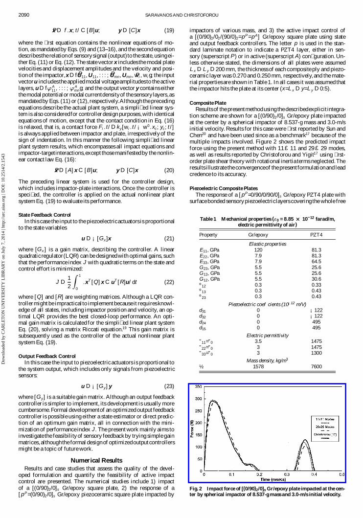
tion scheme are shown for a [(0/90)2/0]s Gr/epoxy plate impactedat the center by a spherical impactor of 8.537-g mass and 3.0-m/sinitial velocity. Results for this case were � rst reported by Sun andChen20 and have been used since as a benchmark17 because of themultiple impacts involved. Figure 2 shows the predicted impactforce using the present method with 11 £ 11 and 29 £ 29 modes,as well as results reported by Christoforou and Yigit17 using � rst-order plate shear theory with rotational inertia terms neglected.Theresults illustrate the convergenceof the present formulationand leadcredence to its accuracy.
Piezoelectric Composite PlatesThe response of a [pP=0/90/0/90/0]s Gr/epoxy PZT4 plate with
surface bonded sensorypiezoelectriclayers covering the whole free
Table 1 Mechanical properties ("0 = 8:85 £ £ 10–12 farad/m,electric permittivity of air)
Property Gr/epoxy PZT4
Elastic propertiesE11, GPa 120 81.3E22, GPa 7.9 81.3E33, GPa 7.9 64.5G23, GPa 5.5 25.6G13, GPa 5.5 25.6G12, GPa 5.5 30.6º12 0.3 0.33º13 0.3 0.43º23 0.3 0.43
Piezoelectric coef� cients (10¡12 m/V)d31 0 ¡122d32 0 ¡122d24 0 495d15 0 495
Electric permittivity"11="0 3.5 1475"22="0 3 1475"33="0 3 1300
Mass density, kg/m3
½ 1578 7600
Fig. 2 Impact force of [(0/90)2/0]s Gr/epoxy plate impacted at the cen-ter by spherical impactor of 8.537-g mass and 3.0-m/s initial velocity.
Dow
nloa
ded
by C
AR
LE
TO
N U
NIV
ER
SIT
Y L
IBR
AR
Y o
n Ju
ly 7
, 201
4 | h
ttp://
arc.
aiaa
.org
| D
OI:
10.
2514
/2.1
543
SARAVANOS AND CHRISTOFOROU 2091
a) Impact force
b) Plate and impactor displacement
c) Electric potential of piezosensor at center of plate
Fig. 3 Response of [p/(0/90)2/0]s Gr/epoxy-PZT4plate impacted at thecenter with the 0.008-kg impactor.
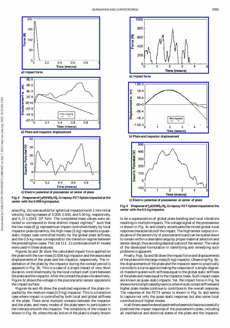
area (Fig. 1b) was studied for spherical impactors with 1 m/s initialvelocity, having masses of 0.008, 0.500, and 5.00 kg, respectively,and ky D 1:234 £ 106 N/m. The considered mass values were se-lected to correspond to three distinct impact regimes,17 such thatthe low mass (8 g) represents an impact controlled mostly by localimpactor-plate dynamics, the high mass (5 kg) represents a quasi-static impact case controlled mostly by the global plate stiffness,and the 0.5-kg mass corresponds to the transition regime betweenthe precedingtwo cases.The � rst 11 £ 11 combinationsof kl modeswere used in these analyses.
Figures 3a and 3b show the calculated impact force applied onthe plate with the low-mass (0.008-kg) impactor and the associateddisplacements of the plate and the impactor, respectively. The in-dentation of the plate by the impactor during the contact period isapparent in Fig. 3b. This is a case of a single impact of very shortduration, controlledmostly by the local contact coef� cient betweenthe plate and the impactor.After the contact the plate vibrates freely.Figure 3c shows the voltage in the piezoceramic sensor opposite tothe impact surface.
Figures 4a and 4b show the predicted response of the plate im-pacted by the medium-mass (0.5-kg) impactor. This is a transitioncase where impact is controlled by both local and global stiffnessof the plate. There exist multiple contacts between the impactorand the plate, and many modes of the plate seem to participate inthe interactions with the impactor. The complexity of the impact isshown in Fig. 4b, where the de� ection of the plate is clearly shown
a) Impact force
b) Plate and impactor displacement
c) Electric potential of piezosensor at center of plate
Fig. 4 Response of [p/(0/90)2/0]s Gr/epoxy-PZT4plate impacted at thecenter with the 0.5-kg impactor.
to be a superposition of global plate bending and local vibrationsresulting in multiple impacts. The voltage signal of the piezosensoris shown in Fig. 4c and clearly accentuates the mixed global-localresponse characteristicsof the impact. The high sensor output is in-dicative of the sensitivity of piezoceramicsand can be scaled downto remain within a desirable range by proper material selection andsensor design, thus avoiding depolarizationof the sensor. The valueof the developed formulation in identifying and remedying suchproblems is apparent.
Finally, Figs. 5a and 5b show the impact force and displacementsof the plate with the large-mass (5-kg) impactor. Observing Fig. 5b,the displacements of the plate and the impactor seem to practicallycoincide to a curve approximating the response of a single-degree-of-freedom system with stiffness equal to the global static stiffnessof the plate and mass equal to the impactor mass. Such impact casesare known as quasi-static impacts. Yet, the impact force in Fig. 5ashowsmore complicateddynamics,wherelocalcontactstiffnessandhigher plate modes continue to contribute to the overall response.The response of the PZT4 sensor is shown in Fig. 5c and seemsto capture not only the quasi-static response, but also some localcontributionsof higher modes.
In all threecases thedevelopedmethodseems to havesuccessfullypredicted the impact response of the piezoelectric plate, includingall mechanical and electrical states of the plate and the impactor.
Dow
nloa
ded
by C
AR
LE
TO
N U
NIV
ER
SIT
Y L
IBR
AR
Y o
n Ju
ly 7
, 201
4 | h
ttp://
arc.
aiaa
.org
| D
OI:
10.
2514
/2.1
543
2092 SARAVANOS AND CHRISTOFOROU
a) Impact force
b) Plate and impactor displacement
c) Electric potential of piezosensor at center of plate
Fig. 5 Response of [p/(0/90)2/0]s Gr/epoxy-PZT4plate impacted at thecenter with the 5-kg impactor.
Moreover, the results show that the piezoceramic sensor providesbetter monitoring of impact dynamics, compared to plate displace-ment, and might combine information directly related to the impactforce.The technicalsigni� canceof thisobservationis apparent,con-sidering the associated dif� culties in monitoring impact force. Anadditional issue emanating from these impact studies is the possibil-ity to control impact response,using either state or output feedbackto the piezoelectric actuators. The active impact control issue isaddressed in the following paragraphs.
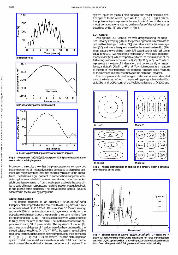
Active Impact ControlThe impact response of an adaptive f[(0/90)2/0]s =pP =pAg
Gr/epoxy plate impacted at the center with a 0.5-kg mass at 1 m/sis considered with ky D 1:234 £ 106 N/m. One 0.125-mm sensoryand one 0.250-mm active piezoceramic layer were bonded on theopposite to the impact side of the plate with their common interfacebeing grounded (Fig. 1c). The piezoelectric layers were assumedto fully cover the area of the plate. The system response was ap-proximated using 3 £ 3 plate modes. The equations of motion (9)and the structuraldegreesof freedom were further condensed to thethree displacementsfU gkl D fU 0 , V 0, W 0gkl by assuming negligiblerotational inertias. In the case of central impact, only the odd modes(1, 1), (1, 3), (3, 1), and (3, 3) are excited, thus the plate-impactorsystem model involves 26 state variables, of which 24 describe theamplitudes of the modal velocities and de� ections of the plate. The
system inputs are the four amplitudes of the modal electric poten-tial applied to the active layer, u D f’A
11, ’ A13, ’A
31 , ’A33g. Each ac-
tive potential input represents the amplitude of one of the spatialmodal voltage patterns applied on the surface of the active layer, asdescribed by Eq. (8) and shown in Fig. 6.
LQR ControlTwo optimal LQR controllers were designed using the simpli-
� ed linear system [Eq. (20)] of the precedingmodel. In each case anoptimal feedbackgain matrix [G¤
x ] was calculatedfor the linear sys-tem (20) and was subsequently used in the actual system Eq. (19).In all cases the weighting matrix [R] was diagonal with all termsequal to 0.001. Two weighting matrices [Q] were used in perfor-mance index (22), which respectively force the minimization of thefollowingquadraticexpressions:1) xT [Q]x D q1.w
0 ¡ wi /2, which
represents a measure of indentation, and consequently of impactforce, and 2) xT [Q]x D q2. Pw0 ¡ Pwi /
2 , which represents a measureof the rate of indentationand rate of impact force and also a measureof the momentum difference between the plate and impactor.
The two optimalstate feedbackgain matrices that were calculatedusing the indexes de� ned in the preceding paragraph are identi� edas LQR1 and LQR2 controllers. Weighting factors q1 D 1200 and
Mode 11
Mode 13
Mode 31
Mode 33
Fig. 6 Modal distributions of applied and sensory electric potentialover the area of the plate.
Fig. 7 Impact force of active f [(0/90)2 /0]s/pP/pA g Gr/epoxy PZT4plate: without control; with LQR1 optimized for force minimization;and with LQR2 optimizedfor relative impactor-platevelocity minimiza-tion. Central impact with 0.5-kg mass and 1-m/s initial velocity.
Dow
nloa
ded
by C
AR
LE
TO
N U
NIV
ER
SIT
Y L
IBR
AR
Y o
n Ju
ly 7
, 201
4 | h
ttp://
arc.
aiaa
.org
| D
OI:
10.
2514
/2.1
543
SARAVANOS AND CHRISTOFOROU 2093
q2 D 200 were selected througha trial and error procedure,such thateach active modal potential remained within the range of §200 V.The tuning of these weighting factors provides a way to safeguardagainst high applied voltages, which can depolarize the piezoce-ramic actuator.
Figure 7 shows the impact force obtained using the gain matrixof the LQR1 controller on the actual plant system [Eq. (19)], whichgains were speci� ed to minimize the integral of the impact force ofthe linearsystem(20).Figure 7 also shows the impact forceobtainedusing the gain matrix of the LQR2 controller, which was speci� ed
a)
b)
c)
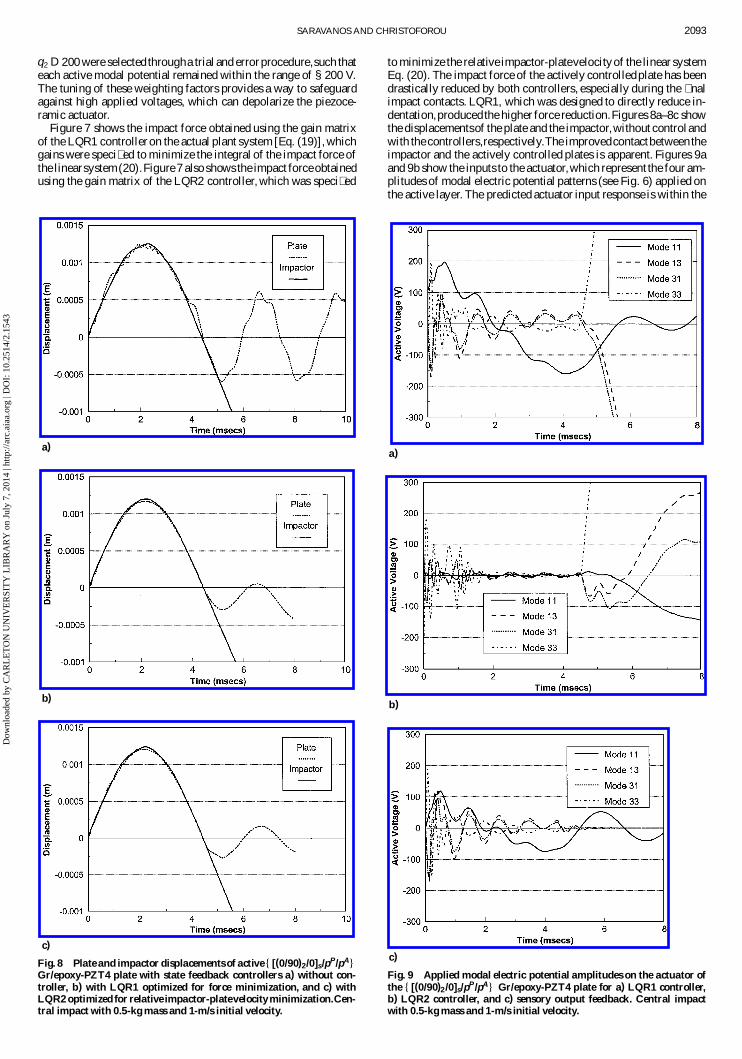
Fig. 8 Plate and impactor displacements of active f [(0/90)2/0]s/pP/pA gGr/epoxy-PZT4 plate with state feedback controllers a) without con-troller, b) with LQR1 optimized for force minimization, and c) withLQR2 optimized for relative impactor-platevelocity minimization.Cen-tral impact with 0.5-kg mass and 1-m/s initial velocity.
to minimize the relative impactor-platevelocityof the linear systemEq. (20). The impact force of the actively controlledplate has beendrastically reduced by both controllers, especially during the � nalimpact contacts. LQR1, which was designed to directly reduce in-dentation,produced the higher force reduction.Figures 8a–8c showthe displacementsof the plate and the impactor,without controlandwith the controllers,respectively.The improvedcontactbetween theimpactor and the actively controlled plates is apparent. Figures 9aand 9b show the inputs to the actuator,which represent the four am-plitudes of modal electric potential patterns (see Fig. 6) applied onthe active layer. The predicted actuator input response is within the
a)
b)
c)
Fig. 9 Applied modal electric potential amplitudes on the actuator ofthe f [(0/90)2 /0]s/pP /pA g Gr/epoxy-PZT4 plate for a) LQR1 controller,b) LQR2 controller, and c) sensory output feedback. Central impactwith 0.5-kg mass and 1-m/s initial velocity.
Dow
nloa
ded
by C
AR
LE
TO
N U
NIV
ER
SIT
Y L
IBR
AR
Y o
n Ju
ly 7
, 201
4 | h
ttp://
arc.
aiaa
.org
| D
OI:
10.
2514
/2.1
543
2094 SARAVANOS AND CHRISTOFOROU
response speed of most piezoceramicmaterials.All applied electricpotential amplitudes remained within the §200-V range, indicatingthat the potential problem of excessively high input voltages canbe addressed and resolved by the proposed controller design proce-dure. In both cases the reduction in impact force has been achievedby improving and extending the contact between the impactor andthe plate. In the case of LQR1 controller, this seems to have beenmostly attained by inducing small active bending de� ections in theplate to reduce its relativeposition to the impactor.This observationis reinforced by the more uniform actuator inputs shown in Fig. 8aand particularly by the higher actuation of the fundamental mode.In the case of the LQR2 controller, the contactwas mostly improvedby actively damping the plate such that its relative vibration to theimpactor was reduced. In both cases energy has been removed fromthe system through the active layer, as indicated by the highly re-duced vibration amplitude of the plate after impact.
The obtained remarkableperformanceof the LQR controller suf-fers in practical implementation. It requiresmeasurement and feed-back of all state variables, including the impactor position and ve-locity, and also becauseof the latter the actuator inputskeep steadilyincreasing after the termination of impact with undesirable effects.However, the precedingcases illustratedthe feasibilityof active im-pact control and validate the proposedapproach for LQR controllerdesign using the simpli� ed linear system.
Output Feedback ControlThe performance of an output feedback controller was in-
vestigated using a diagonal matrix of uniform gains [K y ] =diag(k; : : : ; k). The system output was considered to be the modalcurrent density amplitudes of the piezoelectric sensor provided byEq. (12), that is, y D .J P
11 , J P13 , J P
31, J P33/ with modal paterns shown in
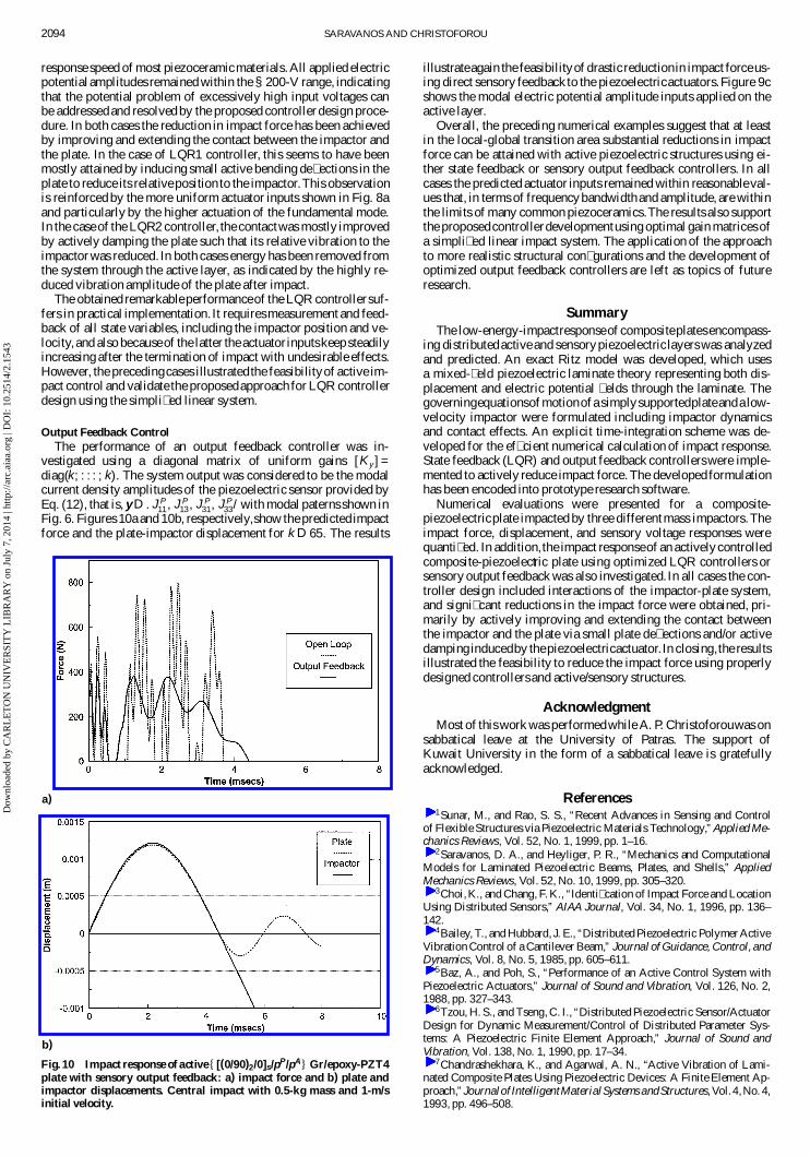
Fig. 6. Figures 10a and 10b, respectively,show the predicted impactforce and the plate-impactor displacement for k D 65. The results
a)
b)
Fig. 10 Impact response of active f [(0/90)2/0]s/pP/pA g Gr/epoxy-PZT4plate with sensory output feedback: a) impact force and b) plate andimpactor displacements. Central impact with 0.5-kg mass and 1-m/sinitial velocity.
illustrateagain the feasibilityof drastic reductionin impact forceus-ing direct sensory feedback to the piezoelectricactuators.Figure 9cshows the modal electric potential amplitude inputs applied on theactive layer.
Overall, the preceding numerical examples suggest that at leastin the local-global transition area substantial reductions in impactforce can be attained with active piezoelectric structures using ei-ther state feedback or sensory output feedback controllers. In allcases the predicted actuator inputs remained within reasonableval-ues that, in terms of frequencybandwidthand amplitude, are withinthe limits of many common piezoceramics.The results also supportthe proposedcontrollerdevelopmentusing optimal gain matrices ofa simpli� ed linear impact system. The application of the approachto more realistic structural con� gurations and the development ofoptimized output feedback controllers are left as topics of futureresearch.
SummaryThe low-energy-impactresponseof compositeplates encompass-
ing distributedactive and sensorypiezoelectric layers was analyzedand predicted. An exact Ritz model was developed, which usesa mixed-� eld piezoelectric laminate theory representing both dis-placement and electric potential � elds through the laminate. Thegoverningequationsofmotionofa simplysupportedplateanda low-velocity impactor were formulated including impactor dynamicsand contact effects. An explicit time-integration scheme was de-veloped for the ef� cient numerical calculation of impact response.State feedback (LQR) and output feedback controllerswere imple-mented to actively reduce impact force. The developed formulationhas been encoded into prototype research software.
Numerical evaluations were presented for a composite-piezoelectricplate impacted by three differentmass impactors.Theimpact force, displacement, and sensory voltage responses werequanti� ed. In addition,the impact responseof an actively controlledcomposite-piezoelectric plate using optimized LQR controllers orsensory output feedback was also investigated. In all cases the con-troller design included interactions of the impactor-plate system,and signi� cant reductions in the impact force were obtained, pri-marily by actively improving and extending the contact betweenthe impactor and the plate via small plate de� ections and/or activedamping inducedby thepiezoelectricactuator.In closing,the resultsillustrated the feasibility to reduce the impact force using properlydesigned controllers and active/sensory structures.
AcknowledgmentMost of this work was performedwhile A. P. Christoforouwas on
sabbatical leave at the University of Patras. The support ofKuwait University in the form of a sabbatical leave is gratefullyacknowledged.
References1Sunar, M., and Rao, S. S., “Recent Advances in Sensing and Control
of Flexible Structures via Piezoelectric Materials Technology,”Applied Me-chanics Reviews, Vol. 52, No. 1, 1999, pp. 1–16.
2Saravanos, D. A., and Heyliger, P. R., “Mechanics and ComputationalModels for Laminated Piezoelectric Beams, Plates, and Shells,” AppliedMechanics Reviews, Vol. 52, No. 10, 1999, pp. 305–320.
3Choi,K., and Chang, F. K., “Identi� cation of Impact Force and LocationUsing Distributed Sensors,” AIAA Journal, Vol. 34, No. 1, 1996, pp. 136–142.
4Bailey, T., and Hubbard, J. E., “Distributed Piezoelectric Polymer ActiveVibration Control of a Cantilever Beam,” Journal of Guidance, Control, andDynamics, Vol. 8, No. 5, 1985, pp. 605–611.
5Baz, A., and Poh, S., “Performance of an Active Control System withPiezoelectric Actuators,” Journal of Sound and Vibration, Vol. 126, No. 2,1988, pp. 327–343.
6Tzou, H. S., and Tseng, C. I., “Distributed Piezoelectric Sensor/ActuatorDesign for Dynamic Measurement/Control of Distributed Parameter Sys-tems: A Piezoelectric Finite Element Approach,” Journal of Sound andVibration, Vol. 138, No. 1, 1990, pp. 17–34.
7Chandrashekhara, K., and Agarwal, A. N., “Active Vibration of Lami-nated Composite Plates Using Piezoelectric Devices: A Finite Element Ap-proach,”Journalof IntelligentMaterialSystems andStructures, Vol. 4,No. 4,1993, pp. 496–508.
Dow
nloa
ded
by C
AR
LE
TO
N U
NIV
ER
SIT
Y L
IBR
AR
Y o
n Ju
ly 7
, 201
4 | h
ttp://
arc.
aiaa
.org
| D
OI:
10.
2514
/2.1
543

SARAVANOS AND CHRISTOFOROU 2095
8Ray, M. C., “Optimal Control of Laminated Plate with PiezoelectricSensor and Actuator Layers,” AIAAJournal, Vol. 36, No. 12, 1998,pp. 2204–2208.
9Liu, G. R., Peng, X. Q., Lam, K. Y., and Tani, J., “Vibration ControlSimulation of Laminated Composite Plates with Integrated Piezoelectrics,”Journal of Sound and Vibration, Vol. 220, No. 5, 1999, pp. 827–846.
10Volpe, R., and Khosla, P., “A Theoretical and Experimental Investiga-tion of Impact Control for Manipulators,” International Journal of RoboticsResearch, Vol. 12, No. 4, 1993, pp. 351–365.
11Tornambe, A., “Global Regulation of a Planar Robot Arm Striking aSurface,” IEEE Transactions on Automatic Control, Vol. 41, No. 10, 1996,pp. 1517–1521.
12Weng, S. W., and Young, K., “An Impact Control Scheme Inspired byHuman Re� ex,” Journal of RoboticSystems, Vol. 13, No. 12, 1996, pp. 837–855.
13Birman, V., Chandrashekhara, K., and Sukhendu, S., “Global Strengthof Hybrid Shape Memory Composite Plates Subjected to Low-Velocity Im-pact,” Journal of Reinforced Plastics and Composites, Vol. 16, No. 9, 1997,pp. 791–809.
14Librescu, L., and Na, S., “Dynamic Response Control of Thin-WalledBeams to Blast Pulses Using Structural Tailoring and Piezoelectric Actua-
tion,” Journal of Applied Mechanics, Vol. 65, No. 2, 1998, pp. 497–504.15Yigit, A. S., and Christoforou, A. P., “Control of Low-Velocity Impact
Response in Composite Plates,” Journal of Vibration and Control, Vol. 6,No. 6, 2000, pp. 429–447.
16Saravanos, D. A., “Coupled Mixed-Field Laminate Theory and FiniteElement for Smart Piezoelectric Composite Shell Structures,”AIAA Journal,Vol. 35, No. 8, 1997, pp. 1327–1333.
17Christoforou, A. P., and Yigit, A. S., “Characterization of Impact inComposite Structures,” Composite Structures, Vol. 43, No. 1, 1998, pp. 15–24.
18Saravanos, D. A., “Damped Vibration of Composite Plates with PassivePiezoelectric-Resistor Elements,” Journal of Soundand Vibration, Vol. 221,No. 5, 1999, pp. 867–885.
19Sage, A. P., and White, C. C., Optimum Systems Control, Prentice–Hall,Upper Saddle River, NJ, 1977, pp. 87–123.
20Sun, C. T., and Chen, J. K., “On the Impact of Initially Stressed Com-posite Laminates,” Journal of Composite Materials, Vol. 19, No. 6, 1985,pp. 490–504.
A. M. BazAssociate Editor
Dow
nloa
ded
by C
AR
LE
TO
N U
NIV
ER
SIT
Y L
IBR
AR
Y o
n Ju
ly 7
, 201
4 | h
ttp://
arc.
aiaa
.org
| D
OI:
10.
2514
/2.1
543

This article has been cited by:
1. Theofanis S. Plagianakos, Evangelos G. Papadopoulos. 2014. Low-energy impact response of composite andsandwich composite plates with piezoelectric sensory layers. International Journal of Solids and Structures . [CrossRef]
2. Tarapada Roy, Debabrata Chakraborty. 2009. Optimal vibration control of smart fiber reinforced composite shellstructures using improved genetic algorithm. Journal of Sound and Vibration 319:1-2, 15-40. [CrossRef]
3. Tarapada Roy, Debabrata Chakraborty. 2009. Genetic algorithm based optimal design for vibration control ofcomposite shell structures using piezoelectric sensors and actuators. International Journal of Mechanics and Materialsin Design 5:1, 45-60. [CrossRef]
Dow
nloa
ded
by C
AR
LE
TO
N U
NIV
ER
SIT
Y L
IBR
AR
Y o
n Ju
ly 7
, 201
4 | h
ttp://
arc.
aiaa
.org
| D
OI:
10.
2514
/2.1
543