Embed Size (px)
Citation preview

IMPACT OF LEAD-FREE COMPONENTS AND TECHNOLOGY SCALING FOR HIGH RELIABILITY APPLICATIONS
Chris Bailey, Ph.D.
University of Greenwich London, United Kingdom
[email protected] ABSTRACT Semiconductor technology is increasingly meeting the demands and challenges posed by roadmaps such as ITRS in terms of technology scaling and packaging, where the interconnect size is decreasing to ever smaller dimensions. The drive for this is increasing functionality of the devices and is governed primarily by the consumer electronics markets. For applications in high reliability sectors such as aerospace, automotive, oil and gas, etc, this scaling in technology, and the use of lead-free solders to satisfy ROHS legislation, is posing a number of challenges. This paper discusses current status in using lead-free components for high reliability applications and developments in modelling that can aid organisations in assessing different design options before using lead-free COTS components in their applications. Key words: Lead-free, refinishing, technology scaling, metal migration and reliability INTRODUCTION Semiconductor companies are now focused on the consumer electronics sector where market size is now significantly greater than the high reliability sector. For example the high reliability sector now only accounts for <1% of electronics components matket. The life-times required for components in this sector are much shorter that that required for the high reliability sectors. Microelectronics components are increasingly manufactured and packaged as “lead-free” as a result of legislations such as the EU RoHS directive. This directive restricts the use of lead and other hazardous substances. As the manufacturing of defense, aerospace and other high-reliability equipment relies more and more on the use of commercial-of-the-shelf (COTS) components, the use of electronics parts with pure or tin-rich alloy finishes on their terminations becomes a major reliability issue due to the problem of tin whisker growth (see figure 1).
Figure 1: Tin Whiskers For Hi-Reliability equipment manufacturers, one possible response to the tin whisker risk is to 're-finish' component terminations, replacing tin-rich termination materials with tin-lead by a process known as hot-solder dipping. This approach, originally developed as a manual 'hand dipping' technique, has migrated to a robotically controlled system (see figure 2) and a more repeatable process available from a limited number of suppliers.
Figure 2: Robot Controlled Solder Refinishing (Courtesy: Micross Components Limited)
As originally published in the SMTA Proceedings.
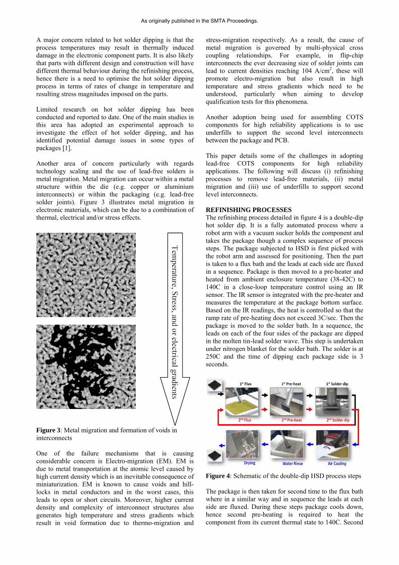
A major concern related to hot solder dipping is that the process temperatures may result in thermally induced damage in the electronic component parts. It is also likely that parts with different design and construction will have different thermal behaviour during the refinishing process, hence there is a need to optimise the hot solder dipping process in terms of rates of change in temperature and resulting stress magnitudes imposed on the parts. Limited research on hot solder dipping has been conducted and reported to date. One of the main studies in this area has adopted an experimental approach to investigate the effect of hot solder dipping, and has identified potential damage issues in some types of packages [1]. Another area of concern particularly with regards technology scaling and the use of lead-free solders is metal migration. Metal migration can occur within a metal structure within the die (e.g. copper or aluminium interconnects) or within the packaging (e.g. lead-free solder joints). Figure 3 illustrates metal migration in electronic materials, which can be due to a combination of thermal, electrical and/or stress effects.
Figure 3: Metal migration and formation of voids in interconnects One of the failure mechanisms that is causing considerable concern is Electro-migration (EM). EM is due to metal transportation at the atomic level caused by high current density which is an inevitable consequence of miniaturization. EM is known to cause voids and hill-locks in metal conductors and in the worst cases, this leads to open or short circuits. Moreover, higher current density and complexity of interconnect structures also generates high temperature and stress gradients which result in void formation due to thermo-migration and
stress-migration respectively. As a result, the cause of metal migration is governed by multi-physical cross coupling relationships. For example, in flip-chip interconnects the ever decreasing size of solder joints can lead to current densities reaching 104 A/cm2, these will promote electro-migration but also result in high temperature and stress gradients which need to be understood, particularly when aiming to develop qualification tests for this phenomena. Another adoption being used for assembling COTS components for high reliability applications is to use underfills to support the second level interconnects between the package and PCB. This paper details some of the challenges in adopting lead-free COTS components for high reliability applications. The following will discuss (i) refinishing processes to remove lead-free materials, (ii) metal migration and (iii) use of underfills to support second level interconnects. REFINISHING PROCESSES The refinishing process detailed in figure 4 is a double-dip hot solder dip. It is a fully automated process where a robot arm with a vacuum sucker holds the component and takes the package though a complex sequence of process steps. The package subjected to HSD is first picked with the robot arm and assessed for positioning. Then the part is taken to a flux bath and the leads at each side are fluxed in a sequence. Package is then moved to a pre-heater and heated from ambient enclosure temperature (38-42C) to 140C in a close-loop temperature control using an IR sensor. The IR sensor is integrated with the pre-heater and measures the temperature at the package bottom surface. Based on the IR readings, the heat is controlled so that the ramp rate of pre-heating does not exceed 3C/sec. Then the package is moved to the solder bath. In a sequence, the leads on each of the four sides of the package are dipped in the molten tin-lead solder wave. This step is undertaken under nitrogen blanket for the solder bath. The solder is at 250C and the time of dipping each package side is 3 seconds.
Figure 4: Schematic of the double-dip HSD process steps The package is then taken for second time to the flux bath where in a similar way and in sequence the leads at each side are fluxed. During these steps package cools down, hence second pre-heating is required to heat the component from its current thermal state to 140C. Second
As originally published in the SMTA Proceedings.

solder dip of the package leads follows. The double-dip approach is utilized to ensure the quality of the re-finishing. The next steps in the process involve air cooling followed by water wash. Drying the package and placement complete the process. A thermal modelling methodology for analysis of the effects of double-dip hot solder dip process on re-finished leaded components has been utilised, demonstrated and validated (2). This exploits the use of finite element analysis which solves the temperature equations over the domain of the package. Figure 5 details such a model representation of the HSD process.
Figure 5: Finite element model of the HSD process The above modelling approach has been applied to a particular Quad Flat Package where transient temperature changes in the package during the HSD process have been predicted and compared against thermocouple data. Figure 5 details the temperature calculations from such as model where we can clearly see the effect of the dipping process on the temperatures in the package. The model predictions were validated against thermo-couple data (see figure 5). The modelling results on the QFP part in the reported study have been extremely beneficial in identifying issues related to the re-finishing process, process instrumentation, and the accuracy of obtained thermocouple measurements. In addition tmodel has supported also the assessment of the performance of cooling rates in the HSD e process and for characterisation the effects of tooling (component mounting) on the component temperatures.
Figure 6: Thermal modeling results and comparisons with thermocouple data USE OF UNDERFIILLS FOR SECOND LEVEL INTERCONNECTS To help increase the reliability and lifetime of COTS components a number of organisations are using underfills at the second level interconnects between package and PCB. The following modelling analysis, although using lead-based solders illustrates that care needs to be undertaken when choosing an underfill for this type of application.
In this study a PBGA packaged is analysed. It is 35x35 mm in size and has a full array (1152) of solder joints at 1 mm pitch size. A copper stiffener at the peripheral area of the package provides structural integrity between the substrate and copper heat spreader. Figure 7 illustrates the PBGA slice model with colours representing different materials. A detailed view at the solder joint level and the mesh across the joint is also provided. The package is modelled in detail so that all layers and materials in the vertical build up of the package are represented. Appropriate boundary conditions for the slice modelled are applied.
As originally published in the SMTA Proceedings.

Figure 7: Finite element model for PBGA The solder material (63Sn/37Pb) is assumed to behave in visco-plastic manner according to an inelastic strain rate relationship. The rest of the materials are elastic with temperature dependent properties. The board is orthotropic. Transient stress and inelastic strain analysis of PBGA finite element model under temperature cycling is used to identify the most damaged solder joints and to calculate a damage parameter based on creep strain energy. It was found that the corner solder joint has the highest value of damage. The two solder joints beneath the edge of the silicon die follow closely. Figure 8 illustrates a typical distribution of accumulated inelastic strain energy density in the solder joints at the end of the thermal cycle (a certain field profile); the location of highest damage in solder is identified near the package interface where the crack is expected to occur.
Figure 8: Energy density [Pa] in PBGA solder joints.
Figure 9 illustrates the accumulated inelastic strain energy density after a thermal cycle in the most damaged solder joint as function of the underfill selection. It was found that underfills A and B both improve solder joint reliability providing a reduction in damage (crack growth rate) up to 60%. However, underfills C and D unfortunately increase damage by up to 4X. Therefore care must be taken in choosing the correct underfill.
Figure 9: Impact of underfill properties.
TECHNOLOGY SCALING Trends in semiconductor packaging and the use of lead-free materials is causing a number of concerns particularly in the high reliability sectors (aerospace, oil&gas, etc) where increasingly the use of commercial off the shelf components are used. One of these concerns is metal migration due to stress, electrical and thermal gradients. At the die level the move towards smaller technology nodes (e.g. down to 32nm and below) and for solder interconnect of much finer pitch and smaller size the risk of metal migration is a concern in particular for components that are required to survive in the field for 10 or more years.
The TTF model [3] for stress migration failure mechanism provided in JEDEC standard is exponentially related to the hydrostatic stresses in the metal line, as shown in the following equation
TTF = Bo * (σ)–N * exp(Eaa / kT) (7)
Where Bo = pre-factor, σ = constant stress load, N = 2 to 3 for ductile metals, Eaa = apparent activation energy, 0.5 to 0.6 eV for grain-boundary diffusion; ~1 eV forsingle-grain (bamboo-like) diffusion, k = Boltzmann’s constant, T = temperature in kelvins.
It is interesting to note that in the JEDEC standard the time to failure is a function of stress magnitude and not stress gradient. Stress migration (SM) or stress induced voiding (SIV) is a failure mechanism often occurs in IC metallization such as the aluminium interconnects. Hydrostatic stress and hydrostatic stress gradient are considered as the driving forces for the void nucleation and growth respectively (4). The void is likely to form at the sites where the stresses are high, but voids would not grow without the presentence of the stress gradients.
Underfill D Underfill C
No Underfill
Underfill A
Underfill B Damage in Solder
Joint Increases
.350E5
.312E5
.274E5
.237E5
.199E5
.161E5
.123E5
.856E4
.478E4
.100E4
Solder Joints
Most Damaged Corner Solder Joint
Damaged Joints beneath Die Edge
MAX
Towards corner of Package
PCB
Die
PBGA Substrate Stiffner
Pad
Solder Mack
Pad
Heat Spreader
Coldwall
PBGA SLICE MODEL
S
olde
r Joi
nt
As originally published in the SMTA Proceedings.

As mentioned above, metal-migration is affected by many factors that are difficult to decouple. Recent work (5) has attempted to provide a modelling framework that provides a multi-physics/scale approach to predicting metal migration. In this work, a closely coupled multi-physics modelling method has been proposed (see Fig. 10). It can be used predict atomic concentration and void formation in metals where electro-migration is affected by electrical, thermal, stress, and geometry factors.
Figure 11: Influences for electro, thermal and stress migration on void formation in metal tracks.
The above numerical values correspond with the analytical solution given by R.L. de Orio and his colleagues (6) for metal migration when only electric effects are considered. It is interesting to see that the numerical results show that including thermal and stress gradients does indeed show a greater degree of metal migration demonstrating that both effects should be considered. Although these are just numerical results, experimental studies are ongoing to try and validate the above.
CONCLUSIONS This paper has discussed some of the issues faced by organizations in the high reliability sector when adopting COTS and lead-free components. The paper also details some of the developments in modeling technologies that can aid organizations understand the impact of refinishing lead-free components, using underfills for second level interconnects and identify the impact of technology scaling on failure mechanisms such as metal migration. Figure 10: Integrated modeling approach for metal
migration REFERENCES 1. Sengupta, S et al., “Assessment of
Thermomechanical Damage of Electronic Parts Due to Solder Dipping as a Postmanufacturing Process”, IEEE Transactions on Electronics Packaging Manufacturing, 30(2), 2007, pp. 128-137
To test the model, a one dimensional analysis was used. The computational domain has a length of 100 μm and an electric potential difference was applied at the two ends of the domain generating a uniform electric filed and a constant current. 2. Stoyanov et-al, Thermal Modelling and Optimisation
of Hot Solder Dip Process, Proc IEEE Eurosime conference, pp 1-8, (2012)
In order to test the effect of temperature gradient, a linear temperature profile was imposed. Similarly, a linear hydrostatic stress profile was created to test the stress gradient effect. The values of the temperature and stress gradients are +0.107 C°/m and +0.107 MPa/m. Fig. 11 shows the vacancy concentration at t=800 s for simulations with electric effect only, electric and thermal effects, and all three effects respectively. The results show that the temperature and stress gradient have both had an impact on metal migration.
3. Failure mechanisms and models for semiconductor devices, JEDEC Standard JEP 122F, Nov 2010
4. D. Ang, R.V.Ramanujan, “Hydrostatic Stress and Hydrostatic Stress Gradient in Passivated Copper Interconnects”, Materials Sciences and Engineering A 423 (2006), pp. 157-165
5. Bailey et-al, Modelling metal migration for high reliability components when subjected to thermo-mechanical loading, Proc IEEE EPTC conference, pp1-5 (2012)
6. R.L. de Orio, H. Ceric, S. Selberherr, “Physically based models of electromigration: From Black’s equation to modern TCAD models”, P775-789, Microelecronics Reliability,2010
As originally published in the SMTA Proceedings.


![RELIABILITY ESTIMATION FOR COMPONENTS - [email protected] Delhi](https://img.pdfslide.us/doc/110x75/620a64a6fbd9f168fe058116/reliability-estimation-for-components-emailprotected-delhi.jpg)