Embed Size (px)
Citation preview
58th ICMD 2017
6 - 8 September 2017, Prague, Czech Republic
IMPACT OF DOCKING METHOD ON LOADS IN ELEMENTS FLOATING
DOCK – VESSEL UNIT
Przemysław RAJEWSKI1, Oleh KLYUS2
1,2 Institute of Marine Propulsion Plants Operations, Maritime University of Szczecin, Poland
Abstract
The paper concentrates on how a selected dock surfacing method affects the stresses formation in the
structure of the dock and the vessel hull. Repairs and modernization of underwater hull parts are re-
lated mainly to placing the vessel on a working platform above the waterline. Docking operations are
carried out using floating docks, hoists and slips or, less frequently due to high cost, by entry the ves-
sel in a basin dry dock and draining the water. In each of the mentioned cases the method of support-
ing the bottom part of the hull changes from continuous support to multipoint support, which in ex-
treme cases, may exceed the allowable loads and cause damage to the hull structure. The paper pre-
sents modern docking equipment and includes a discussion on the docking methods for vessels and
technical aspects of the process affecting load variation in accordance with a selected dock surfacing
method.
Key words: vessel docking, floating dock, repairs, docking,
INTRODUCTION
During the operation, a ship is subject to annual inspections proving that its technical condition meets
the standards and requirements of a classification society supervising the ship. The preparation process
for the inspection is usually preceded by conducting repairs. The scope of the inspection is specified in
the classification rules and agreements made between the shipowner and the classification society. A
ship must be a subject of the inspection of the underwater hull part twice in a five-year validity period
of its class certificate (between the second and the third year and after five years of validity period).
Inspections, repairs and modernization of underwater hull parts are related mainly to laying the ship on
the working platform above the waterline. Activities related thereto are considered as a docking opera-
tion. Depending on the weight and dimensions of repaired vessels, shipyard equipment and acceptable
costs, the operations are carried out using floating dry docks, hoists or slips or, less frequently due to
high cost, by entry a vessel in a basin dry dock and draining the water. In each of the mentioned cases
the method of supporting the bottom part of the hull changes from continuous support to multi point
support, which in extreme cases, may exceed the allowable loads and cause damages to the hull struc-
ture (Rules for classification floating docks, Chapter, 2 Steel hull structures, DNV.GL, Edition Octo-
ber 2015). Upon having a docking date agreed, technical service of the shipowner provides a docking
plan to the shipyard. Docking plan is a document developed by the shipyard constructing the vessel
and includes essential information for the shipyard prior to docking the ship. Before the ship is docked
it is necessary to carry out a number of preparatory activities related to the docking procedure, provid-
ing power and meeting the requirements for environment protection. In order to reduce the stresses of
the vessel bottom where keel block it supports, it is required to remove cargo (load), petroleum waste,
and to reduce the volume of ballast water to a minimum ensuring the stability of the ship entering the
dock. The fuel amount should be also reduced to the least possible level. In order to facilitate docking
the ship and grounding she on keels, it is aimed to keep the ship on a plate keel, without trimming of
the ship. Upon the completion of the preparatory activities, a summary in a form of a table is devel-
oped. It shall include vessel weight, the arrangement of loads, the volume of fluids in tanks, draught.
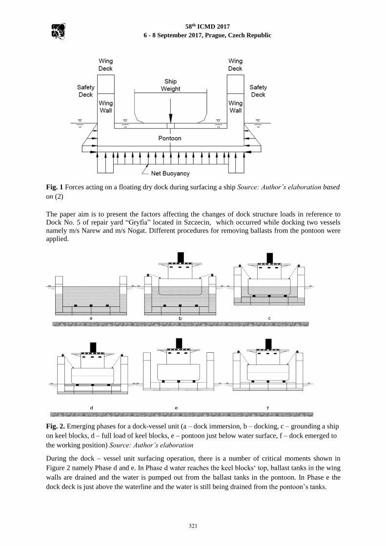
Figure 1 presents forces acting on the floating dry dock – vessel unit during emerging the ship above
the waterline.
320
58th ICMD 2017
6 - 8 September 2017, Prague, Czech Republic
Fig. 1 Forces acting on a floating dry dock during surfacing a ship Source: Author’s elaboration based
on (2)
The paper aim is to present the factors affecting the changes of dock structure loads in reference to
Dock No. 5 of repair yard “Gryfia” located in Szczecin, which occurred while docking two vessels
namely m/s Narew and m/s Nogat. Different procedures for removing ballasts from the pontoon were
applied.
Fig. 2. Emerging phases for a dock-vessel unit (a – dock immersion, b – docking, c – grounding a ship
on keel blocks, d – full load of keel blocks, e – pontoon just below water surface, f – dock emerged to
the working position) Source: Author’s elaboration
During the dock – vessel unit surfacing operation, there is a number of critical moments shown in
Figure 2 namely Phase d and e. In Phase d water reaches the keel blocks‘ top, ballast tanks in the wing
walls are drained and the water is pumped out from the ballast tanks in the pontoon. In Phase e the
dock deck is just above the waterline and the water is still being drained from the pontoon’s tanks.
321
58th ICMD 2017
6 - 8 September 2017, Prague, Czech Republic
The dock – vessel unit stability is the least in the said immersion phases. Even the slight tilt of the
pontoon in Phase e may result in water overflowing to one sideboard and the dock stability is
disturbed (6). Such a situation has occurred in April 2017 in a Polish shipyard.
MATERIALS AND METHODS
The complexity of activities related to preparing and docking a ship may result in the occurrence of
threats and risks for safe docking operation. The main reason for this to happen is local exceedance of
allowable stresses of dock structure or docked ship. The design values of bending moment and trans-
verse strength related with loading the dock with the weight of docked ship, dock’s weight along with
water ballast and buoyant force should not be less than (1):
𝑀 = 𝑘𝑚𝑔𝑃𝐷 𝐿𝐷 (1)
𝑄 = 𝑘𝑔𝑔𝑃𝐷 (2)
where M is bending moment (kNm), Q is the value of transverse strength in the dock (kN), km is a
numerical factor of the values provided in Table 1, kq is a numerical factor of the values provided in
Table 1, g – gravitational acceleration (g = 9,81 m/s2 ), PD – dock lifting capacity, [t]; the parameter
the value of which is equal to the weight of the heaviest ship that may be docked in standard dock
operational conditions; LD – dock’s length, [m]; it is a distance between the end walls (transverse
bulkheads) of the pontoon (or pontoons), measured in the plane of the symmetry of the dock.
Tab. 1 km and kq values (1)
Dock lifting capacity
PD [t]
km 1 kq
≤ 40 000 0,0333 0,13
≥ 70 000 0,0195 0,08
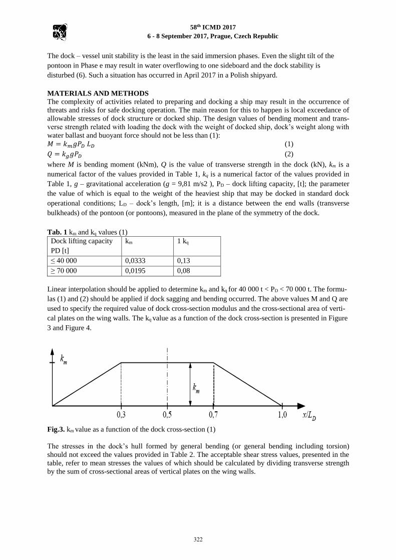
Linear interpolation should be applied to determine km and kq for 40 000 t < PD < 70 000 t. The formu-
las (1) and (2) should be applied if dock sagging and bending occurred. The above values M and Q are
used to specify the required value of dock cross-section modulus and the cross-sectional area of verti-
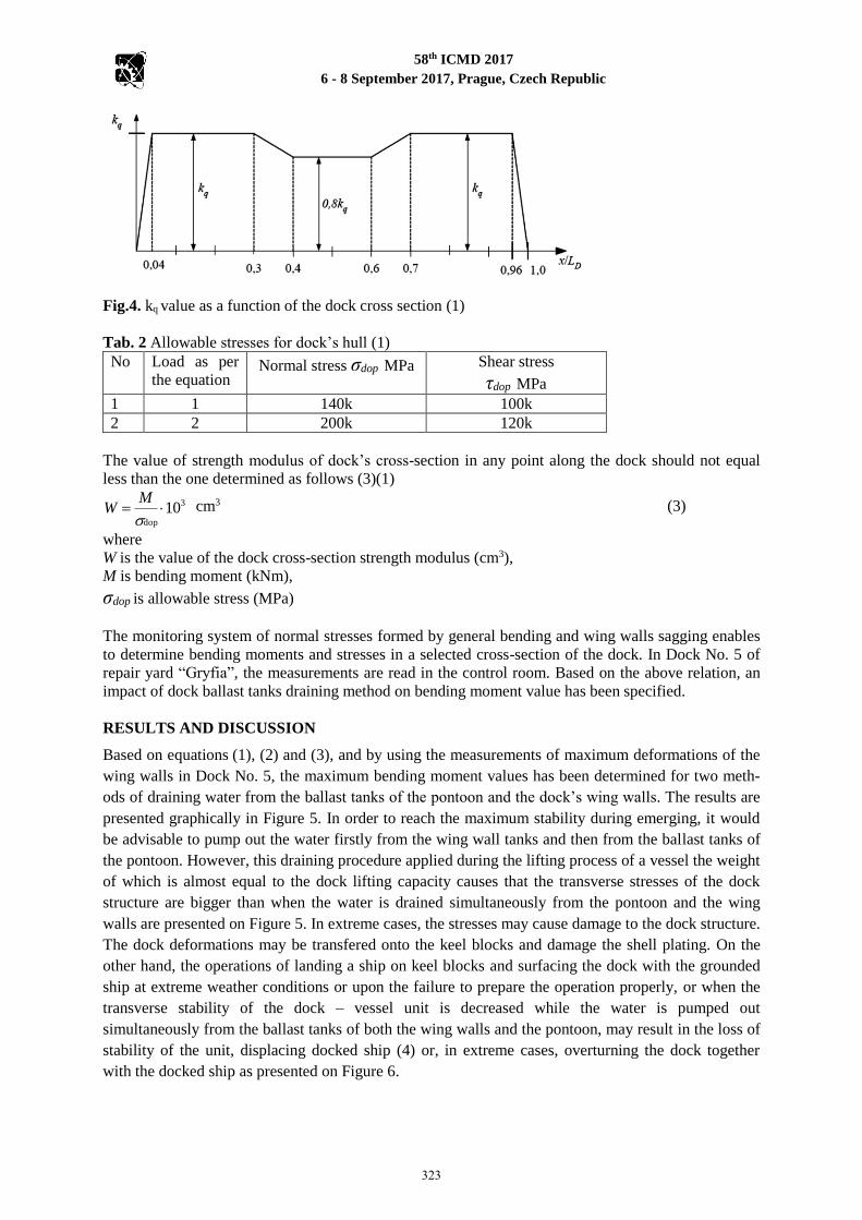
cal plates on the wing walls. The kq value as a function of the dock cross-section is presented in Figure
3 and Figure 4.
Fig.3. km value as a function of the dock cross-section (1)
The stresses in the dock’s hull formed by general bending (or general bending including torsion)
should not exceed the values provided in Table 2. The acceptable shear stress values, presented in the
table, refer to mean stresses the values of which should be calculated by dividing transverse strength
by the sum of cross-sectional areas of vertical plates on the wing walls.
322
58th ICMD 2017
6 - 8 September 2017, Prague, Czech Republic
Fig.4. kq value as a function of the dock cross section (1)
Tab. 2 Allowable stresses for dock’s hull (1)
No Load as per
the equation Normal stress σdop MPa
Shear stress
τdop MPa
1 1 140k 100k
2 2 200k 120k
The value of strength modulus of dock’s cross-section in any point along the dock should not equal
less than the one determined as follows (3)(1)
3
dop
10
MW cm3 (3)
where
W is the value of the dock cross-section strength modulus (cm3),
M is bending moment (kNm),
σdop is allowable stress (MPa)
The monitoring system of normal stresses formed by general bending and wing walls sagging enables
to determine bending moments and stresses in a selected cross-section of the dock. In Dock No. 5 of
repair yard “Gryfia”, the measurements are read in the control room. Based on the above relation, an
impact of dock ballast tanks draining method on bending moment value has been specified.
RESULTS AND DISCUSSION
Based on equations (1), (2) and (3), and by using the measurements of maximum deformations of the
wing walls in Dock No. 5, the maximum bending moment values has been determined for two meth-
ods of draining water from the ballast tanks of the pontoon and the dock’s wing walls. The results are
presented graphically in Figure 5. In order to reach the maximum stability during emerging, it would
be advisable to pump out the water firstly from the wing wall tanks and then from the ballast tanks of
the pontoon. However, this draining procedure applied during the lifting process of a vessel the weight
of which is almost equal to the dock lifting capacity causes that the transverse stresses of the dock
structure are bigger than when the water is drained simultaneously from the pontoon and the wing
walls are presented on Figure 5. In extreme cases, the stresses may cause damage to the dock structure.
The dock deformations may be transfered onto the keel blocks and damage the shell plating. On the
other hand, the operations of landing a ship on keel blocks and surfacing the dock with the grounded
ship at extreme weather conditions or upon the failure to prepare the operation properly, or when the
transverse stability of the dock – vessel unit is decreased while the water is pumped out
simultaneously from the ballast tanks of both the wing walls and the pontoon, may result in the loss of
stability of the unit, displacing docked ship (4) or, in extreme cases, overturning the dock together
with the docked ship as presented on Figure 6.
323
58th ICMD 2017
6 - 8 September 2017, Prague, Czech Republic
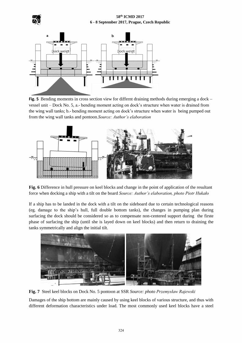
Fig. 5 Bending moments in cross section view for differnt draining methods during emerging a dock –
vessel unit – Dock No. 5, a.- bending moment acting on dock’s structure when water is drained from
the wing wall tanks; b.- bending moment acting on dock’s structure when water is being pumped out
from the wing wall tanks and pontoon.Source: Author’s elaboration
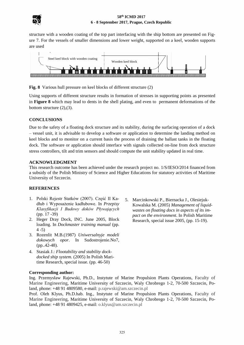
Fig. 6 Difference in hull pressure on keel blocks and change in the point of application of the resultant
force when docking a ship with a tilt on the board Source: Author’s elaboration, photo Piotr Hukało
If a ship has to be landed in the dock with a tilt on the sideboard due to certain technological reasons
(eg. damage to the ship’s hull, full double bottom tanks), the changes in pumping plan during
surfacing the dock should be considered so as to compensate non-centered support during the firste
phase of surfacing the ship (until she is layed down on keel blocks) and then return to draining the
tanks symmetrically and align the initial tilt.
Fig. 7 Steel keel blocks on Dock No. 5 pontoon at SSR Source: photo Przemysław Rajewski
Damages of the ship bottom are mainly caused by using keel blocks of various structure, and thus with
different deformation characteristics under load. The most commonly used keel blocks have a steel
324
58th ICMD 2017
6 - 8 September 2017, Prague, Czech Republic
structure with a wooden coating of the top part interfacing with the ship bottom are presented on Fig-
ure 7. For the vessels of smaller dimensions and lower weight, supported on a keel, wooden supports
are used
Fig. 8 Various hull pressure on keel blocks of different structure (2)
Using supports of different structure results in formation of stresses in supporting points as presented
in Figure 8 which may lead to dents in the shell plating, and even to permanent deformations of the
bottom structure (2),(3).
CONCLUSIONS
Due to the safety of a floating dock structure and its stability, during the surfacing operation of a dock
– vessel unit, it is advisable to develop a software or application to determine the landing method on
keel blocks and to monitor on a current basis the process of draining the ballast tanks in the floating
dock. The software or application should interface with signals collected on-line from dock structure
stress controllers, tilt and trim sensors and should compute the unit stability updated in real time.
ACKNOWLEDGMENT
This research outcome has been achieved under the research project no. 1/S/IESO/2014 financed from
a subsidy of the Polish Ministry of Science and Higher Educations for statutory activities of Maritime
University of Szczecin.
REFERENCES
1. Polski Rejestr Statków (2007). Część II Ka-
dłub i Wyposażenie kadłubowe. In Przepisy
Klasyfikacji I Budowy doków Pływających
(pp. 17 -39)
2. Heger Dray Dock, INC. June 2005, Block
loading. In Dockmaster training manual (pp.
4 -5)
3. Rozenlit M.B.(1987) Uniwersalnyje modeli
dokowych opor. In Sudostrojenie.No7,
(pp..42-48).
4. Stasiak J.: Flootability and stability dock-
docked ship system. (2005) In Polish Mari-
time Research, special issue. (pp. 46-50)
5. Marcinkowski P., Biernacka J., Olesiejuk-
Kowalska M. (2005) Management of liquid-
wastes on floating docs in aspects of its im-
pact on the environment. In Polish Maritime
Research, special issue 2005, (pp. 15-19).
Corresponding author:
Ing. Przemysław Rajewski, Ph.D., Instytute of Marine Propulsion Plants Operations, Faculty of
Marine Engineering, Maritime University of Szczecin, Waly Chrobrego 1-2, 70-500 Szczecin, Po-
land, phone: +48 91 4809580, e-mail: [email protected]
Prof. Oleh Klyus, Ph.D.hab. Ing., Instytute of Marine Propulsion Plants Operations, Faculty of
Marine Engineering, Maritime University of Szczecin, Waly Chrobrego 1-2, 70-500 Szczecin, Po-
land, phone: +48 91 4809425, e-mail: [email protected]
Steel keel block with wooden coating Wooden keel block
325