Embed Size (px)
Citation preview
1
Impact of Burnout Oven Stripping on Rewound
Motor Reliability and Rewinding Considerations
Thursday, August 24th, 2017
Presented by: Leo Dreisilker – President of Dreisilker Electric Motors, Inc.
2
Motor Repair Standards/Specifications
• Designed to ensure reliable repairs
• Standards are created by:
• National and international organizations
• IEEE, NEMA, EASA, IEC, etc.
• Repair shops
• Motor using companies
• Motor manufacturers
3
Motor Repair Standards/Specifications
PROBLEM: A majority of
standards/specifications contain little or brief
detail on stripping and rewinding of motors.
4
Dangers of Low Quality Rewind Process
• Failure from Loose Windings/Vibration
• Susceptibility to Contamination
• Poor Heat Transfer
• Imbalanced Current and Temperature
• Insulation Failure
• Physical Deformation of Motor Components • Air Gap Change
• Bearing Misalignment
• Warping of Motor Frame
• Soft-Foot

5
Dangers of Low Quality Rewind Process Cont.
• Core Loss
• Efficiency Loss
• Power Factor Decrease
• Increase Operating Costs
• Phase Imbalance
• Metallurgical Change in Electrical
Steel
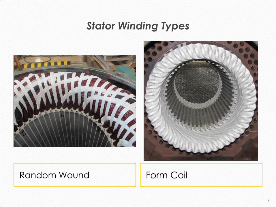
Stator Winding Types
Random Wound Form Coil
6
7
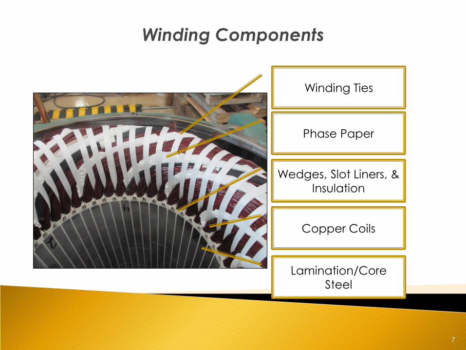
Winding Components
Lamination/Core
Steel
Wedges, Slot Liners, &
Insulation
Phase Paper
Winding Ties
Copper Coils
8
Stator Laminations/Core
• Laminations are made from electrical steel
to channel magnetic fields
• All laminations are individually coated with
an insulator to prevent shorting together
• Lamination steels are designed to prevent
Eddy Currents and Hysteresis Losses
• Electrical steel manufacturers design
laminations for specific electrical
characteristics
9
How are Windings Stripped?
• Burnout Oven Incineration: • Winding insulations are turned to ash at
temperature ranging from 600 °F – 1000 °F
• Flame Thrower/Open Flame Torching: • Flame is applied directly to winding slots to
incinerate motor insulation
• Chemical Bath • Motors are soaked in chemicals that eats away
and softens varnish
• High Pressure Water Blasting • Coils blasted away with extremely high psi water
flow
10
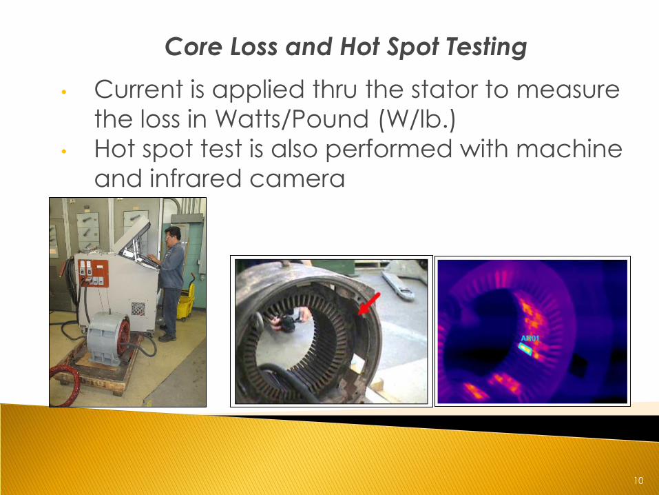
Core Loss and Hot Spot Testing
• Current is applied thru the stator to measure
the loss in Watts/Pound (W/lb.)
• Hot spot test is also performed with machine
and infrared camera
11
Dreisilker Motor Safe Stripping Method
• Gas or Induction Warming with Hydraulic
Pulling
• Stator core is heated with gas or high
frequency induction around 400 °F or
near the insulation class temperature
until copper and varnish softens enough
to pull coil groups out hydraulically
12
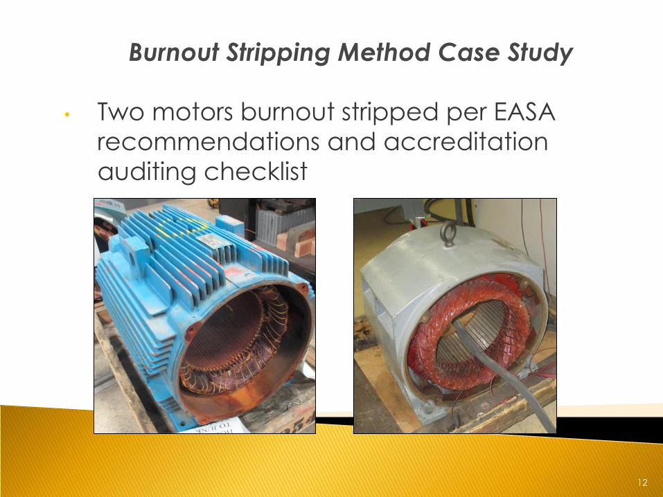
Burnout Stripping Method Case Study
• Two motors burnout stripped per EASA
recommendations and accreditation
auditing checklist
13
Burnout Stripping Method Case Study
• Recommendations [1] and Accreditation Auditing Checklist
[2] for stripping and coil removal:
• 750 ˚F burnout temperature setting for inorganic
laminations
• Set on feet in burnout oven to avoid warpage
• Fire suppression system tested before oven cycle started
• Core loss measured before and after stripping
• Accreditation Auditing Manual allows 20% change
with no baseline of what's an unacceptable value in
W’s/lb.
• Burnout oven was calibrated prior to use
14
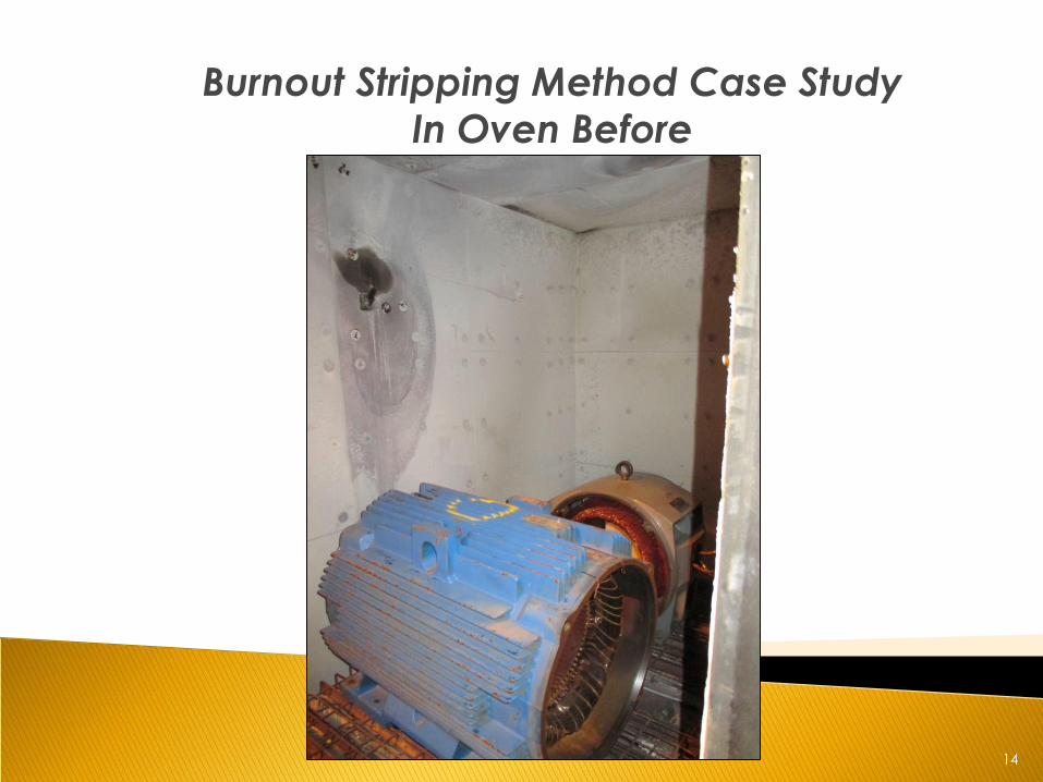
Burnout Stripping Method Case Study
In Oven Before
15
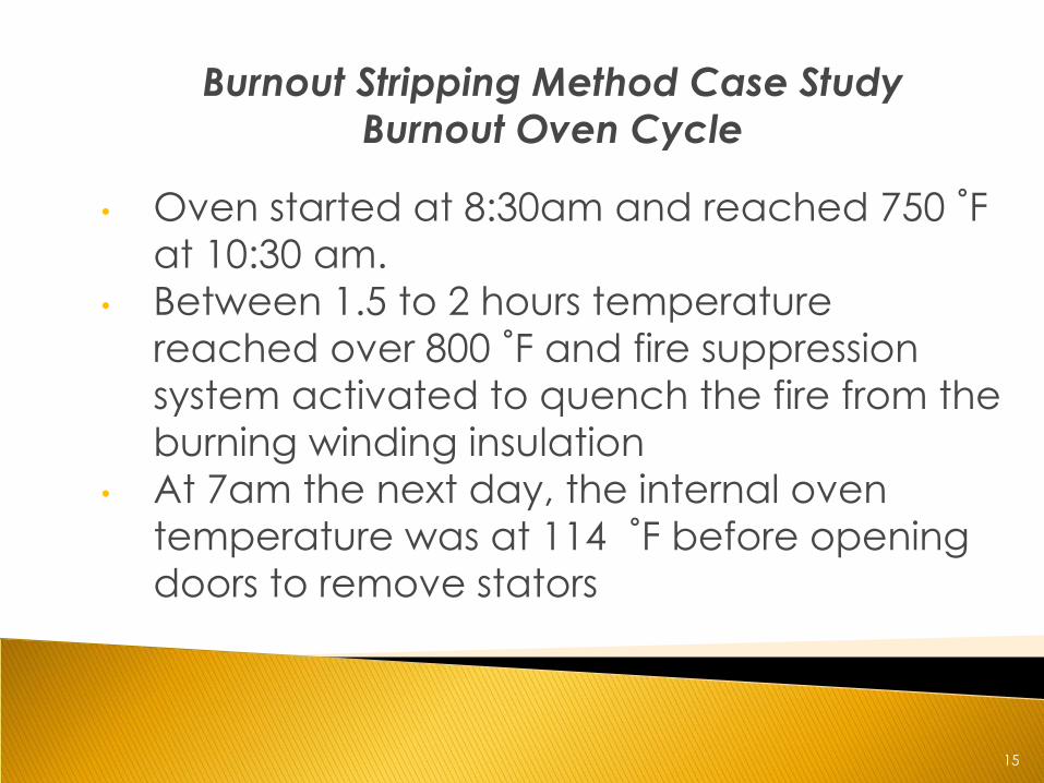
Burnout Stripping Method Case Study
Burnout Oven Cycle
• Oven started at 8:30am and reached 750 ˚F
at 10:30 am.
• Between 1.5 to 2 hours temperature
reached over 800 ˚F and fire suppression
system activated to quench the fire from the
burning winding insulation
• At 7am the next day, the internal oven
temperature was at 114 ˚F before opening
doors to remove stators
16
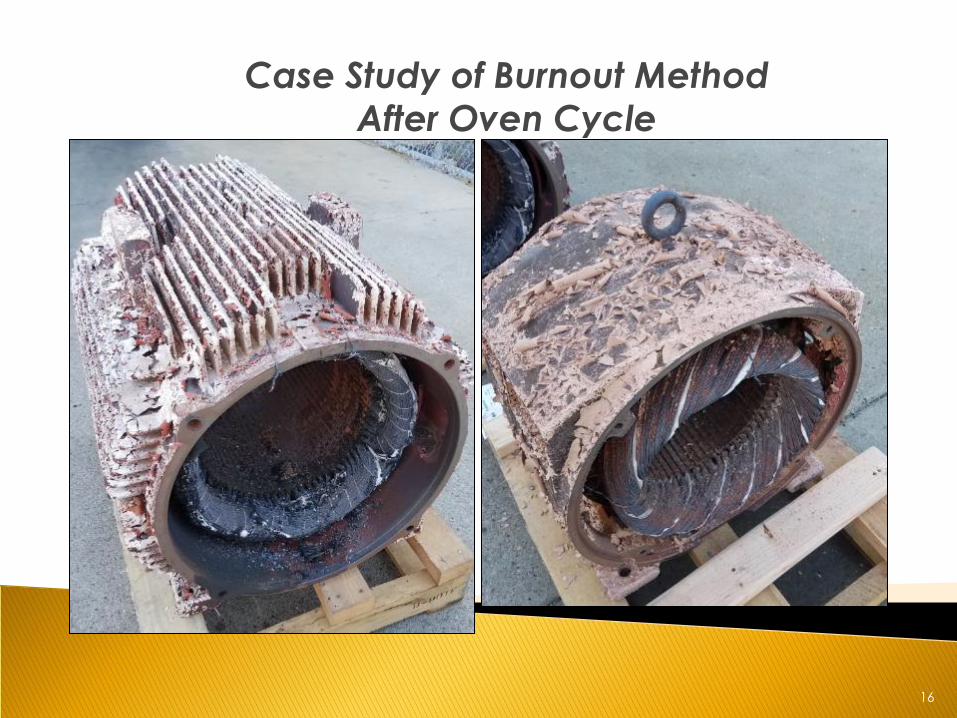
Case Study of Burnout Method
After Oven Cycle
17
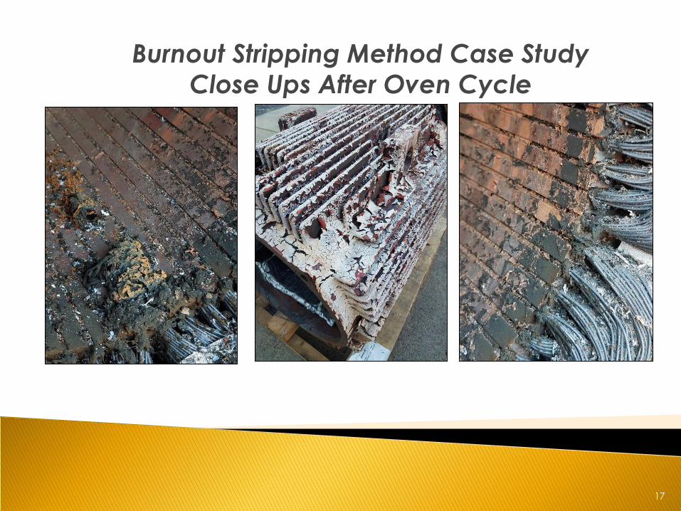
Burnout Stripping Method Case Study
Close Ups After Oven Cycle
18
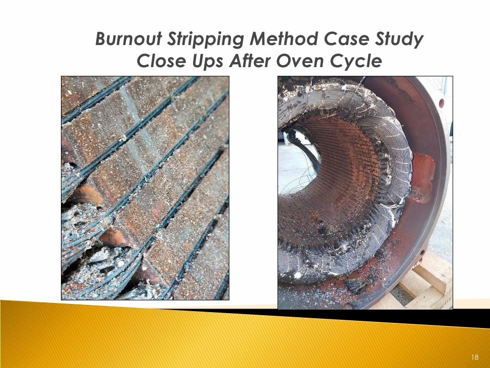
Burnout Stripping Method Case Study
Close Ups After Oven Cycle
19
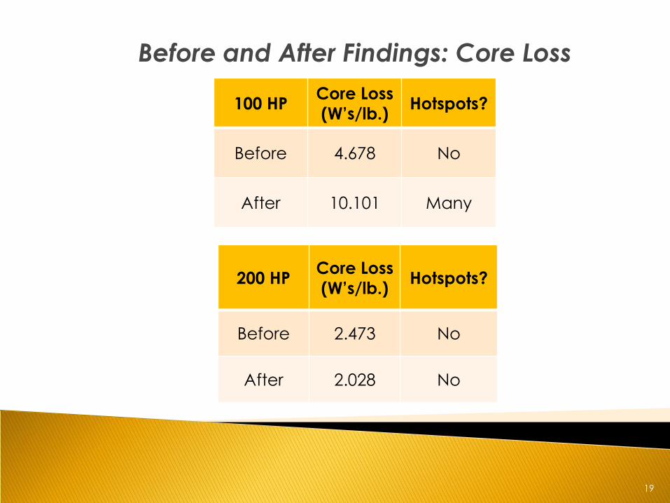
Before and After Findings: Core Loss
100 HP Core Loss
(W’s/lb.) Hotspots?
Before 4.678 No
After 10.101 Many
200 HP Core Loss
(W’s/lb.) Hotspots?
Before 2.473 No
After 2.028 No
20
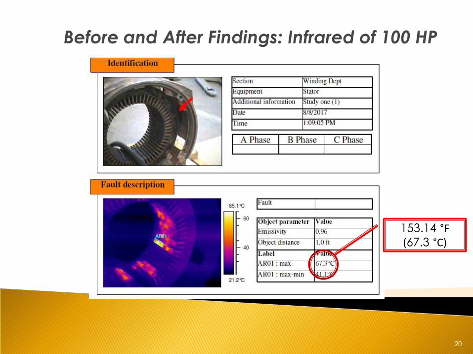
Before and After Findings: Infrared of 100 HP
153.14 °F (67.3 °C)
21
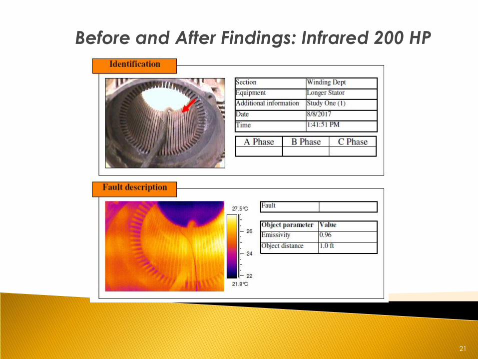
Before and After Findings: Infrared 200 HP
22
Why did Core Loss Decrease for 200 HP?
• Core Loss: 2.473 to 2.028 W’s/lb.
• Why?
• Rust developed from fire suppression
system sauna effect
• Rust(Iron-Oxide) is an insulator
• Rust develops between the motor
laminations
• Five Laminations were removed and
presence of rust was found between
each
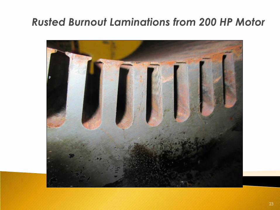
23
Rusted Burnout Laminations from 200 HP Motor
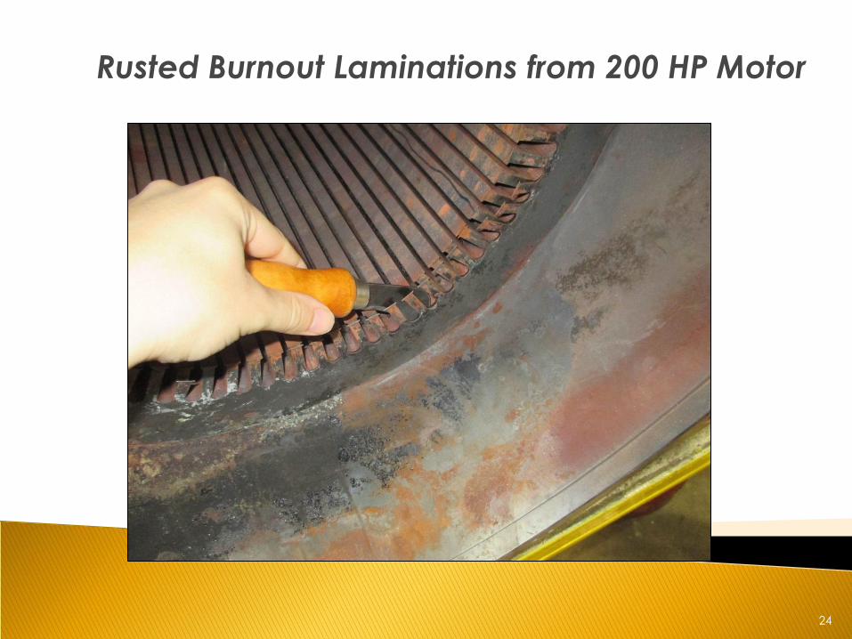
24
Rusted Burnout Laminations from 200 HP Motor
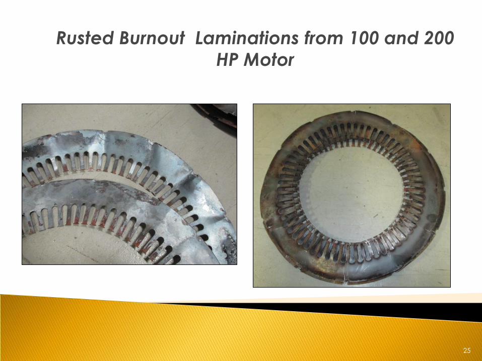
25
Rusted Burnout Laminations from 100 and 200
HP Motor
26
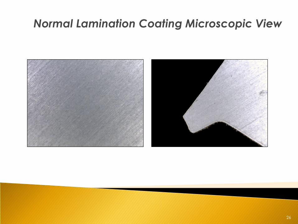
Normal Lamination Coating Microscopic View
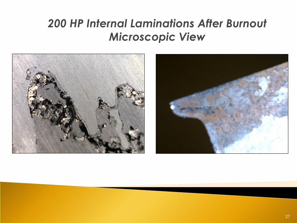
27
200 HP Internal Laminations After Burnout
Microscopic View
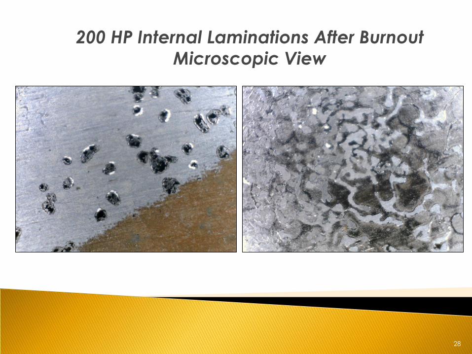
28
200 HP Internal Laminations After Burnout
Microscopic View
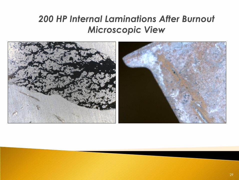
29
200 HP Internal Laminations After Burnout
Microscopic View
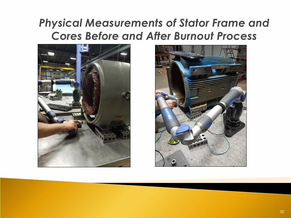
30
Physical Measurements of Stator Frame and
Cores Before and After Burnout Process
31
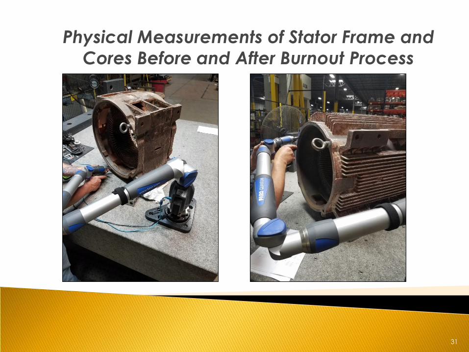
Physical Measurements of Stator Frame and
Cores Before and After Burnout Process
32
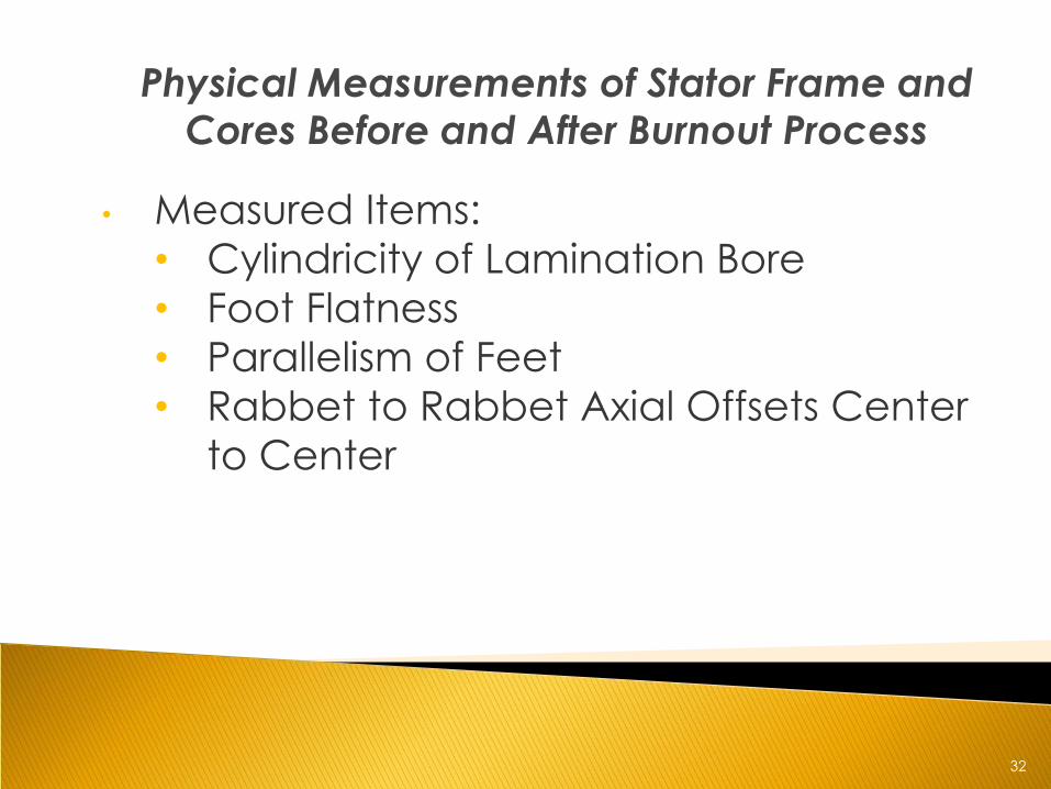
Physical Measurements of Stator Frame and
Cores Before and After Burnout Process
• Measured Items:
• Cylindricity of Lamination Bore
• Foot Flatness
• Parallelism of Feet
• Rabbet to Rabbet Axial Offsets Center
to Center
33
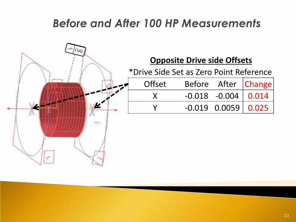
Before and After 100 HP Measurements
Opposite Drive side Offsets
*Drive Side Set as Zero Point Reference
Offset Before After Change
X -0.018 -0.004 0.014
Y -0.019 0.0059 0.025
34
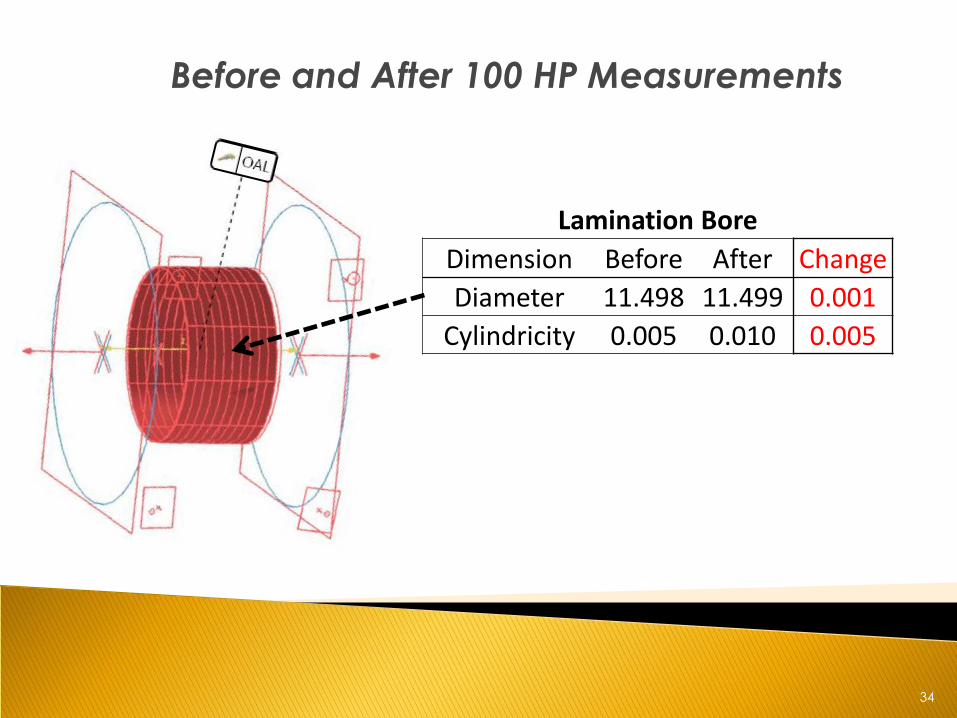
Before and After 100 HP Measurements
Lamination Bore
Dimension Before After Change
Diameter 11.498 11.499 0.001
Cylindricity 0.005 0.010 0.005
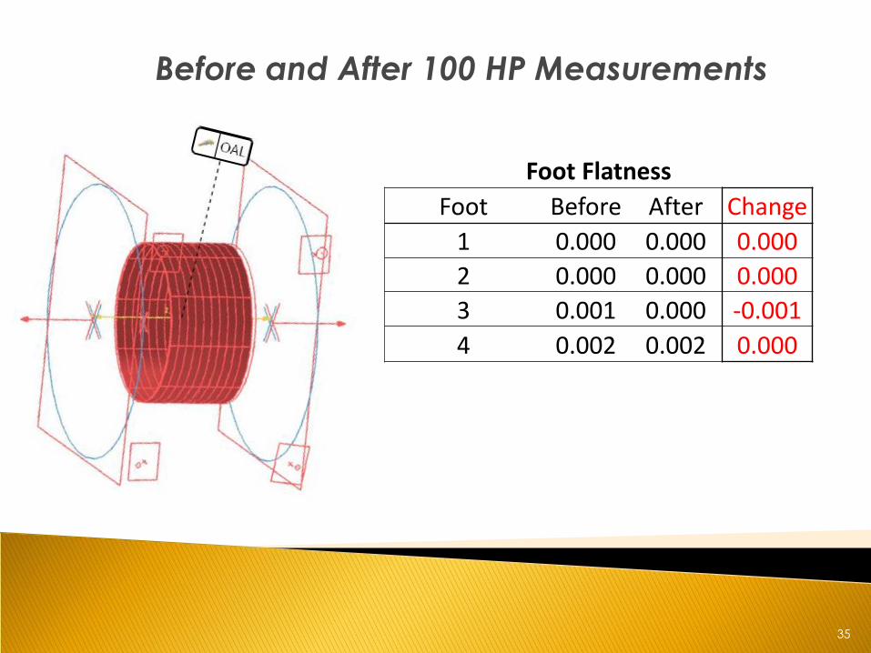
35
Before and After 100 HP Measurements
Foot Flatness
Foot Before After Change
1 0.000 0.000 0.000
2 0.000 0.000 0.000
3 0.001 0.000 -0.001
4 0.002 0.002 0.000
36
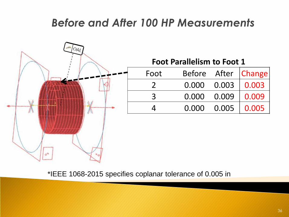
Before and After 100 HP Measurements
*IEEE 1068-2015 specifies coplanar tolerance of 0.005 in
Foot Parallelism to Foot 1
Foot Before After Change
2 0.000 0.003 0.003
3 0.000 0.009 0.009
4 0.000 0.005 0.005
37
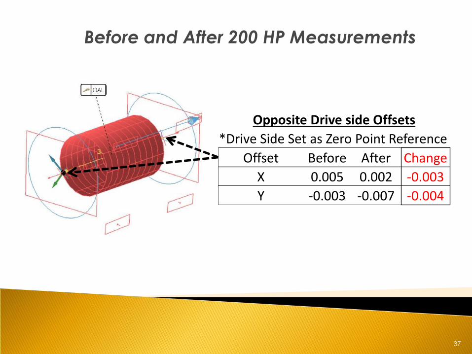
Before and After 200 HP Measurements
Opposite Drive side Offsets
*Drive Side Set as Zero Point Reference
Offset Before After Change
X 0.005 0.002 -0.003
Y -0.003 -0.007 -0.004
38
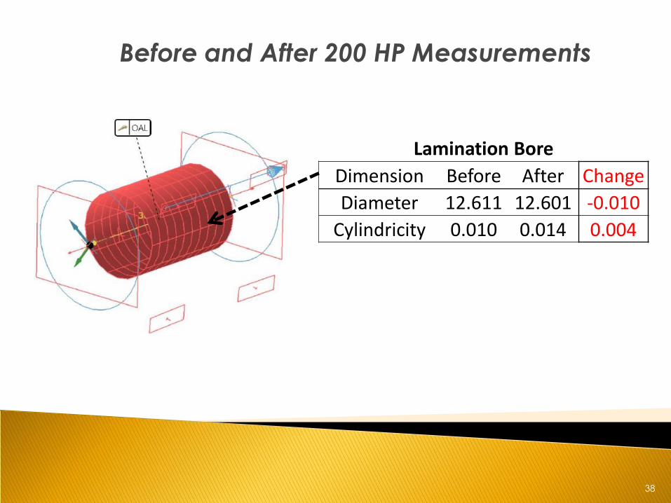
Before and After 200 HP Measurements
Lamination Bore
Dimension Before After Change
Diameter 12.611 12.601 -0.010
Cylindricity 0.010 0.014 0.004
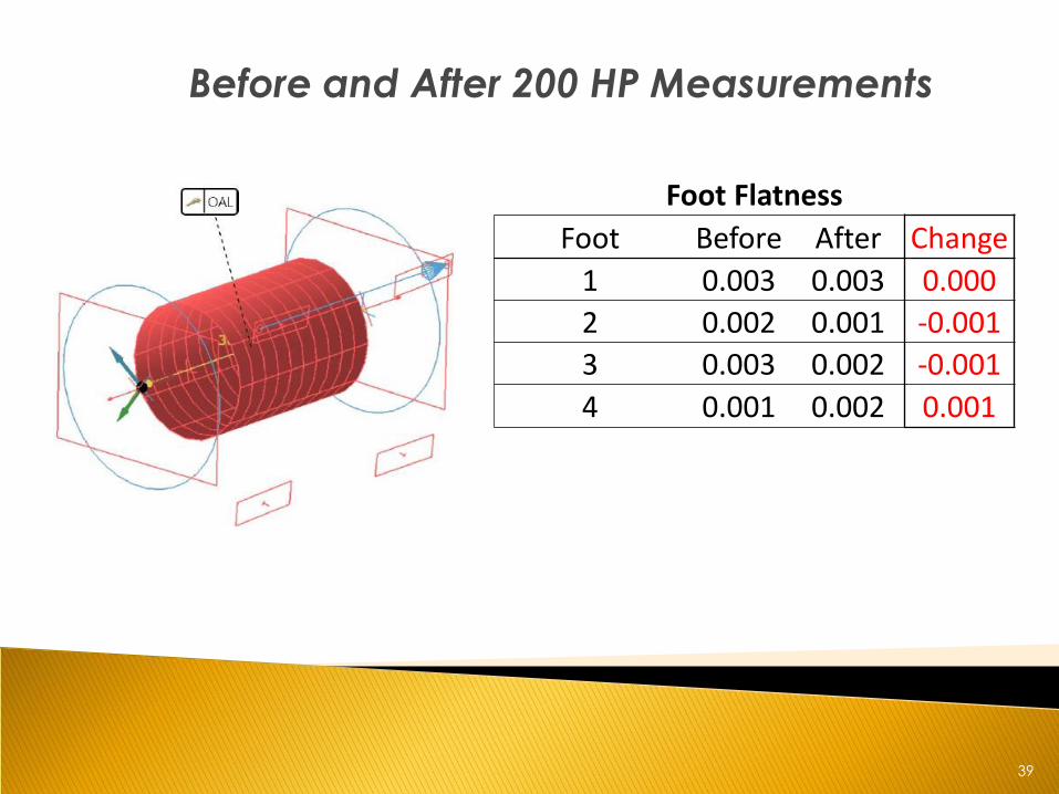
39
Before and After 200 HP Measurements
Foot Flatness
Foot Before After Change
1 0.003 0.003 0.000
2 0.002 0.001 -0.001
3 0.003 0.002 -0.001
4 0.001 0.002 0.001
40
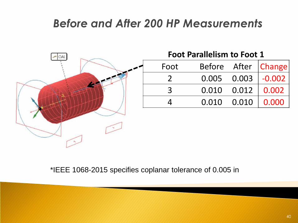
Before and After 200 HP Measurements
*IEEE 1068-2015 specifies coplanar tolerance of 0.005 in
Foot Parallelism to Foot 1
Foot Before After Change
2 0.005 0.003 -0.002
3 0.010 0.012 0.002
4 0.010 0.010 0.000
41
EASA Core Loss Standards
• EASA Standard AR100-2015 Recommended
Practice [1] • “Core temperature should be controlled to
avoid degradation of the interlaminar
insulation and distortion of any parts. The
temperature should not exceed 700 °F(370 °C)
for organic and 750 °F (400 °C) for inorganic
coreplate. If a burnoff oven is used, the oven
should have a water suppression system. Parts
should be oriented and supported in the oven
so as to avoid distortion of the parts.”
42
EASA Core Loss Standards
• Accreditation Audit Checklist [2]
• Mandatory Major Criteria: “If core test
losses increase more than 20% between
the before and after winding removal
tests, the core is repaired or replaced.”
• Examples: • 2.0 W’s/lb., 20% = 2.4
• 6.0 W’s/lb., 20% = 7.2
• 10.0 W’s/lb., 20% = 12 W’s/lb.
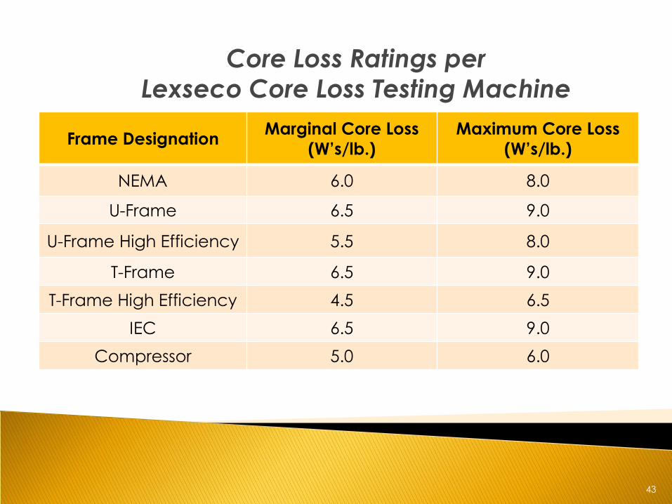
43
Core Loss Ratings per
Lexseco Core Loss Testing Machine
• INSERT
Frame Designation Marginal Core Loss
(W’s/lb.)
Maximum Core Loss
(W’s/lb.)
NEMA 6.0 8.0
U-Frame 6.5 9.0
U-Frame High Efficiency 5.5 8.0
T-Frame 6.5 9.0
T-Frame High Efficiency 4.5 6.5
IEC 6.5 9.0
Compressor 5.0 6.0
44
EASA Core Loss Standards
• The Effect of Repair/Rewinding on Motor Efficiency [3]. • “The EASA/AEMT study confirmed, however,
that testing the core with the loop test or a
commercial tester before and after winding
removal can detect increased losses caused
by burning out and cleaning the core.”
45
EASA Core Loss Document
• The importance of stator core loss testing before and after burn-off process [4]:
• “We also started to see a pattern of motors the were manufactured beginning in the late 1990s that could not be
rewound more than once or twice before core losses
increased well beyond acceptable limits. In some cases, we
found hotspots due to blown copper deposits; grinding and separating them only caused the hot spot to worsen, and
expand in area. In other cases the core was unacceptably hot
overall. Or motors were failing within weeks of being rewound if
they had not been culled out by core loss testing.”
• “These scenarios left us in the unenviable position of having to
explain to a customer that their critical motor was not
repairable after only one rewind…”
46
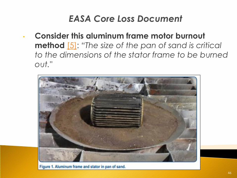
EASA Core Loss Document
• Consider this aluminum frame motor burnout
method [5]: “The size of the pan of sand is critical
to the dimensions of the stator frame to be burned
out."
47
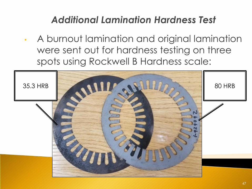
Additional Lamination Hardness Test
• A burnout lamination and original lamination
were sent out for hardness testing on three
spots using Rockwell B Hardness scale:
35.3 HRB 80 HRB
48
Discussion with Motor Manufacturer Metallurgist
• Summary: If you over anneal laminations with a
furnace atmosphere that is humid, then you can develop subsurface oxides. The most common complaint of over-annealing is the subsurface oxides lower the magnetic permeability of the steel.
• Problem: Lowering the permeability of the lamination steel directly lowers the magnetic flux density and creates unknown changes to the steels saturation curve
49
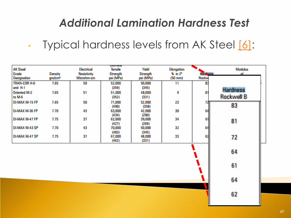
Additional Lamination Hardness Test
• Typical hardness levels from AK Steel [6]:
50
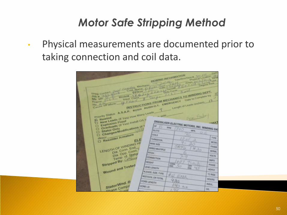
Motor Safe Stripping Method
• Physical measurements are documented prior to taking connection and coil data.
51
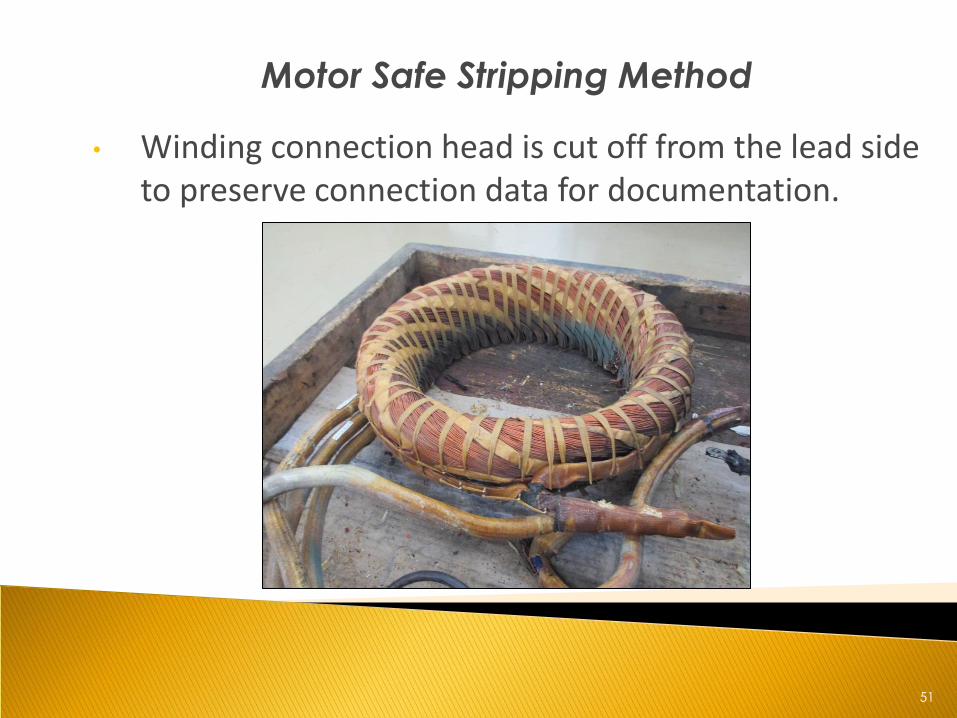
Motor Safe Stripping Method
• Winding connection head is cut off from the lead side to preserve connection data for documentation.
52
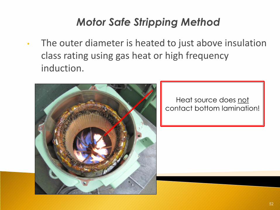
Motor Safe Stripping Method
• The outer diameter is heated to just above insulation class rating using gas heat or high frequency induction.
Heat source does not
contact bottom lamination!
53
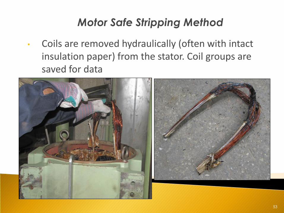
Motor Safe Stripping Method
• Coils are removed hydraulically (often with intact insulation paper) from the stator. Coil groups are saved for data
54
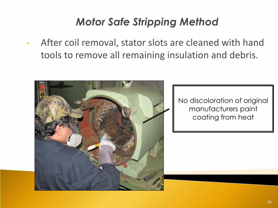
Motor Safe Stripping Method
• After coil removal, stator slots are cleaned with hand tools to remove all remaining insulation and debris.
No discoloration of original
manufacturers paint
coating from heat
55
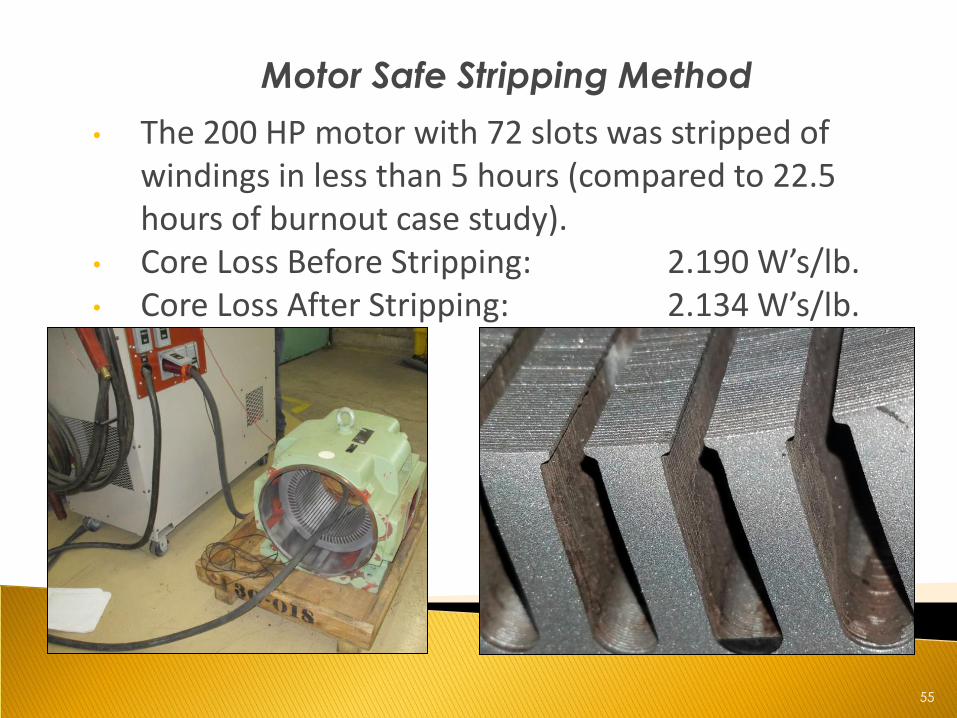
Motor Safe Stripping Method
• The 200 HP motor with 72 slots was stripped of windings in less than 5 hours (compared to 22.5 hours of burnout case study).
• Core Loss Before Stripping: 2.190 W’s/lb. • Core Loss After Stripping: 2.134 W’s/lb.
56
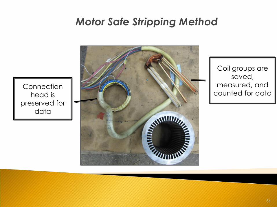
Motor Safe Stripping Method
Connection
head is
preserved for
data
Coil groups are
saved,
measured, and
counted for data
57
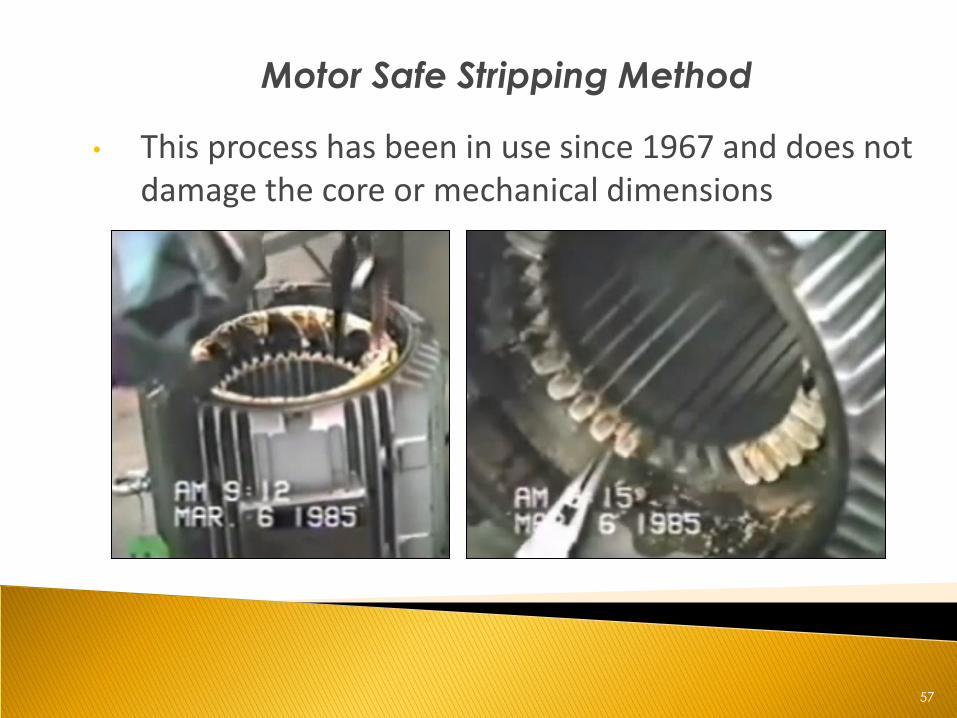
Motor Safe Stripping Method
• This process has been in use since 1967 and does not damage the core or mechanical dimensions
58
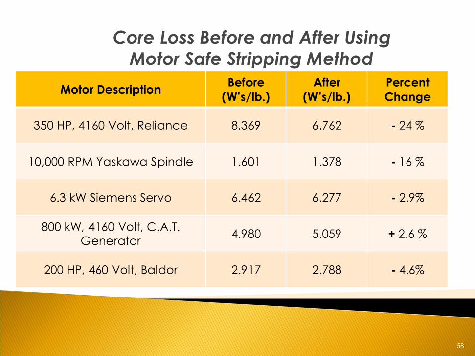
Core Loss Before and After Using
Motor Safe Stripping Method
Motor Description Before
(W’s/lb.)
After
(W’s/lb.)
Percent
Change
350 HP, 4160 Volt, Reliance 8.369 6.762 - 24 %
10,000 RPM Yaskawa Spindle 1.601 1.378 - 16 %
6.3 kW Siemens Servo 6.462 6.277 - 2.9%
800 kW, 4160 Volt, C.A.T.
Generator 4.980 5.059 + 2.6 %
200 HP, 460 Volt, Baldor 2.917 2.788 - 4.6%
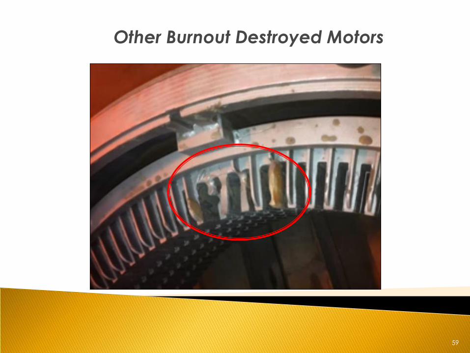
59
Other Burnout Destroyed Motors
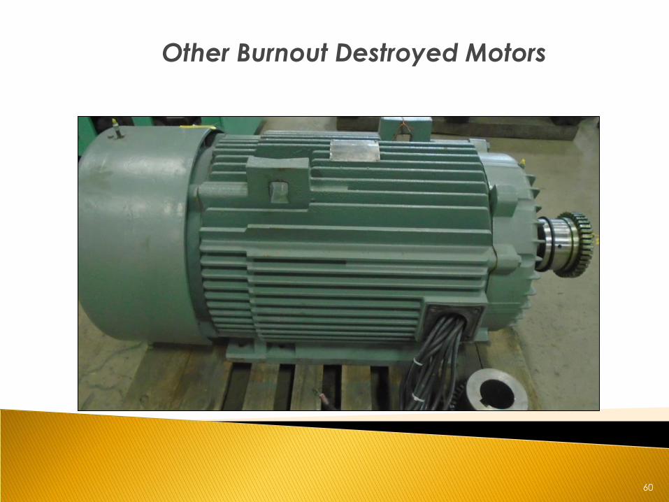
60
Other Burnout Destroyed Motors
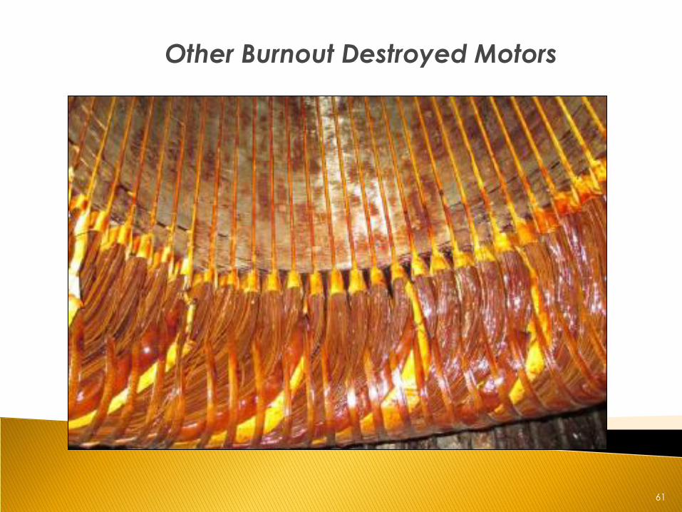
61
Other Burnout Destroyed Motors
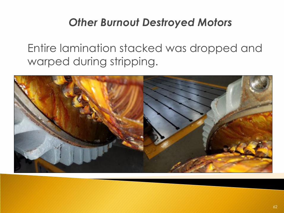
62
Other Burnout Destroyed Motors
Entire lamination stacked was dropped and
warped during stripping.
63
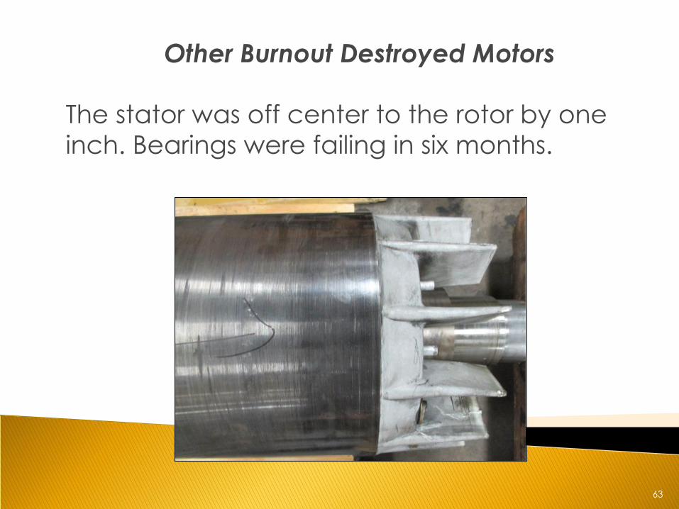
Other Burnout Destroyed Motors
The stator was off center to the rotor by one
inch. Bearings were failing in six months.
64
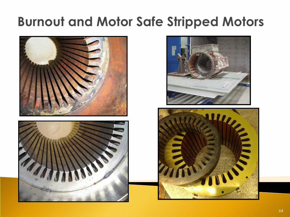
Burnout and Motor Safe Stripped Motors
65
Managing Your Motor Repair Decisions
• Do you have repair specifications?
• Does your repair shop know and follow your
specifications?
• Have you visited your repair shops?
• Are you receiving documentation, data, and repair
reports?
• Who in your organization is your motor repair decision
maker? (Purchasing, Engineering, Maintenance,
Reliability Manager?)
• If you have a standard, does it detail core loss
acceptance testing?
• Is your company managing your new motors and
motor repair as a low cost commodity?
66
Conclusions
• Multiple industry organizations and manufacturers knowingly
accept :
• Core loss increase is an expected result from burnout
oven stripping
• Frames are distorted and warped
• Hotspots cause uneven amperage draw, increased motor
operating temperature, and lower efficiency and power
factor • Rust accumulates between laminations as a result of
insulation degradation during burnout process
• Rusty laminations will falsify core loss test results
• Potential exists for continuous degradation of the core while the motor is in service
67
Conclusions Cont.
• Operating costs increase
• Motor life and reliability decreases
• Motor rewinding ability decreases with core loss
increase during burnout stripping process
68
Bibliography
• [1] ANSI/EASA Standard AR100-2015: Recommended Practice
for the Repair of Rotating Electrical Apparatus:
https://www.easa.com/sites/files/resource_library_public/EASA_AR100-2015_0815_0.pdf
• [2] EASA Accreditation Program Audit Checklist with
Explanations (Ver. 2)
https://www.easa.com/sites/files/accreditation_program/EASA_Accredication_Checklist-wExplanations-0614.pdf
• [3] The Effect of Repair/Rewinding on Motor Efficiency:
EASA/AEMT Rewind Study and Good Practice Guide to
Maintain Motor Efficiency
https://www.easa.com/sites/files/resource_library_public/EASA
_AEMT_RewindStudy_1203-0115.pdf
69
Bibliography Cont.
• [4] The importance of stator core loss testing before and after
burn-off process
https://www.easa.com/system/files/resource_library_private/StatorCoreLossTest-BeforeAfterBurnoff_0614.pdf
• [5] Consider this aluminum frame motor burnout method
https://www.easa.com/system/files/resource_library_private/Al
uminumFrameBurnout_0317.pdf • [6] Selection of electrical steels for magnetic cores
http://www.aksteel.com/pdf/markets_products/electrical/ma
g_cores_data_bulletin.pdf
70
Leo Dreisilker– President
Dreisilker Electric Motors, Inc.
630-469-7510
Thank you