Embed Size (px)
Citation preview

HAL Id: jpa-00253397https://hal.archives-ouvertes.fr/jpa-00253397
Submitted on 1 Jan 1994
HAL is a multi-disciplinary open accessarchive for the deposit and dissemination of sci-entific research documents, whether they are pub-lished or not. The documents may come fromteaching and research institutions in France orabroad, or from public or private research centers.
L’archive ouverte pluridisciplinaire HAL, estdestinée au dépôt et à la diffusion de documentsscientifiques de niveau recherche, publiés ou non,émanant des établissements d’enseignement et derecherche français ou étrangers, des laboratoirespublics ou privés.
Impact damage on silicon carbide : first resultsP. Riou, L. Beylat, C. Cottenot, J.-L. Derep
To cite this version:P. Riou, L. Beylat, C. Cottenot, J.-L. Derep. Impact damage on silicon carbide : first results. Jour-nal de Physique IV Colloque, 1994, 04 (C8), pp.C8-281-C8-287. <10.1051/jp4:1994842>. <jpa-00253397>

JOURNAL DE PHYSIQUE IV Colloque C8, supplkment au Journal de Physique 111, Volume 4, septembre 1994
Impact damage on silicon carbide: first results
P. Riou, L. Beylat, C. Cottenot and J.-L. Derep
ETCAICREA, Ddpartement Matkriaux en Conditions Sdv&res, 16 bis Avenue Prieur de la C6te d'Or, 941 14 Arcueil cedex, France
R6sum6 : L'objectif de ce travail est d'identifier les mkcanismes d'endommagement d'une ckramique lors d'un impact. Dans de nombreux cas, l'amor~age et la propagation de l'endommagement se trouvent localisks dans le c6ne de fissuration de Hertz [I]. Aussi, les essais d'impact men& sur des carreaux de ckramiques ne permettent pas d'obtenir, durant l'essai, d'information sur cette zone. Une nouvelle g6om6trie de cible dite "allumette" permettant de placer des jauges de fissuration B l7int6rieur du c6ne a donc Ct6 dCvelopp6e. Les donn6es expCrimentales ainsi obtenues, couplkes B une analyse microstructurale permettent de valider les rksultats d'une simulation numkrique effectu6e B l'aide d'un code d1616ments finis tridimensionnel.
Abstract : This paper deals with the damage of ceramic materials after impact. The main information on the phenomenology and the kinetic damage are often localized inside the Hertzian cone crack area [I]. With a ceramic tile target, it is not possible to obtain any information during the test. Therefore a new geometry of ceramic target, called "Match was developed in order to put crack gauge inside the Hertzian cone. The relationship between collected experimental data and microstructural studies allow to validate the results of a three dimensional finite element simulation.
1. INTRODUCTION.
During the last years, the number of works on ceramic impact behaviour works has increased following the development of their use as armour. Indeed, ceramics have some physical properties which are very attractive for ballistic applications against different kinds of threats. Among them, we can quote :
- a high hardness which leads to the erosion or the rupture of the projectile, - an ability to uniformly transmit the impact pressure from the front to the back side by the creation of a
cone crack.
This aspect is very attractive in the case of a bilayer armour concept. Nevertheless, the choice of the type of ceramic is mainly based on empirical ballistic performance data. At the present time, the failure phenomenology during penetration is not well understood. As a matter of fact the penetrator induces a complex load in the ceramic. Then conventional material properties, such as thoughness or roughness, correlate poorly with ballistic performances.
The aim of this research is to identify the mechanism responsible for the failure of the ceramic annors and to investigate the microstructure parameters which have a main influence on ballistic performances. The finality of this work is to collect experimental data in order to validate a finite element simulation. This paper presents the results obtained so far.
Article published online by EDP Sciences and available at http://dx.doi.org/10.1051/jp4:1994842

C8-282 JOURNAL DE PHYSIQUE IV
2. MATERIAL AND BALLISTIC TESTS DEVICE
The studied ceramic is Silicon Carbide (Sic), which seems to be the best ceramic for ballistic applications [2]. Sic is supplied by Ceramiques & Composites society and is obtained by pressureless sintering process. Chemical compounds, physical properties and microstructure of S ic are carried out [23]. The porosity is equal to 1.8%. The pore mean size is 1-2 pm, the bigger diameter being 14pm. The grains are equiaxed with a grain mean diameter of 6 p.m. X'ray diffraction study shows that the 6H polytype is the main phase of the ceramic. Nevertheless, the 4H polytype is also encountered. Carbon particles are observed. This particles are constituted by turbostratic fibrilla embedded in an amorphous matrix [3].
A gas gun is used for the ballistic tests. The projectile is a steel cylinder with a 11 mm diameter and a 20 mm length. The velocity range is included between 1 lOds and 320 m/s. These velocities were mesured with optical Infra-Red captors. Used targets are 100x100 mm2 ceramic tiles with different thicknesses between 10 to 25 mm. Ceramic tiles are tested free or with a back side confinement.
3. TILE IMPACT RESULTS
Two main fracture modes are observed during ceramic impact. The damage of the ceramic can be induced by a bending mechanism or can occur by the apparition of an Hertzian cone as it can be seen in figure 1 .a. In the latest case, the impact area is filled in by epoxy resin in order to embedded all the fragments. The observation of a cross section of the impacted zone (figure 1 .a) shows that the Hertzian cone angle is equal to the angle of the maximum tensile stress direction calculated by Roesler (about 65O) in a case of a quasi-stat- ic approach [I]. In this calculation, the material is supposed to be homogeneous, isotropic and to have an elastic behaviour. Path cracks are transgranular and are induced by a cleavage mechanism as it is shown in figure 2. Sometimes little intergranular cracks are also observed. The porosity is measured by image quantita- tive analysis on polished samples and on fracture area. The both results are quite similar. It thus appears that the main cracks path is not influenced by the presence of the pores.
Projectile
- I ' I - - . - - - - =
Fiyure 1 : Cross section of an im~acted target
Thin foils are taken just below the impact area mark 1 and 2 at figure 1 .b. The plane of thin foil (mark 1) is parallel to projectile penetration direction. The plane of the second one (mark 2) is normal to this direction. JEOL 1200EX transmission electron microscope is used to observe the thin foil . The dislocation density is the same in the both cases and is not increased by the impact. Some microcracks with few dislocations around were evidenced in the area 1 as it can be seen in figure no3.
Nevertheless, these microcracks are scarce. It is also important to note that alot of microcracks go through a carbon particle. Then it appears that carbon particles and pores have an important part during the cracks initiation stage but this part becomes negligible during the propagation stage of the macrocraks. Then, with this kind of threat, the damage of ceramic appears to be controlled by a crack propagation mechanism due to a critical tensile stress.
In order to collecte experimental data on crack initiation and propagation, a new geometry of rectangular targets, whose width is similar to projectile diameter, is tested. It is called Match target (cf figure 6).

Figure 2 : Scanning Electronic Microscopv F t 'hansgranular ~ro~agat ion of the crack Microcrack with few dislocations in the area 1
4. IMPACT ON MATCH TARGET
In order to check that the same kind of damage is induced during impact in tile or match targets, prelirninaty tests with two configurations of instrumented match targets were performed (cf figure 4). The rupture of the gauges J1 and J3 in the first case and J2 and J4 in the second case indicates that the front failure is a conoldale crack with the same angle as it is observed on impacted tile target.
Picture no 4 : Preliminarv match target configuration
Concerning a post impact observation on a back side confined match target, the figure 5 clearly shows the presence of the cone crack which stayed glued on back steel confinement. Moreover, rear face failures induced by bending effect are also visible.
C8-284 JOURNAL DE PHYSIQUE IV
The instrumented match target used is shown in figure 6. Several gauges were used. In order to know if crack initiation is on the front or at the rear face, two gauges (J1 and J2) are set on the side of the target. The 53 gauge mesures the crack propagation on the back side area. For this present work, only unconfined match targets were used.
- ceramic match
Fi~ure 6 : Unconfined match target design
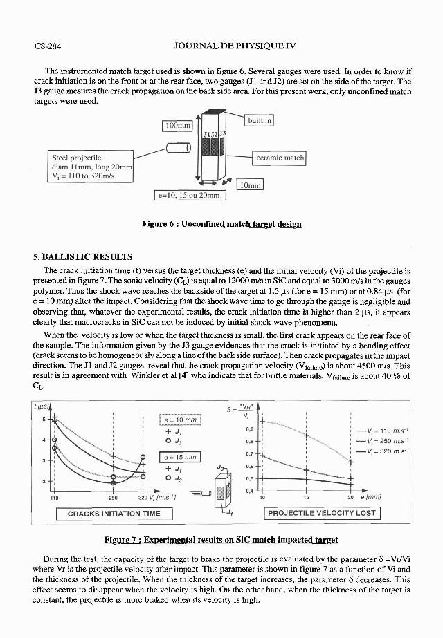
5. BALLISTIC RESULTS The crack initiation time (t) versus the target thickness (e) and the initial velocity (Vi) of the projectile is
presented in figure 7. The sonic velocity (CL) is equal to 12000 mls in S ic and equal to 3000 m/s in the gauges polymer. Thus the shock wave reaches the backside of the target at 1.5 ys (fore = 15 mm) or at 0.84 ps (for e = 10 mm) after the impact. Considering that the shock wave time to go through the gauge is negligible and observing that, whatever the experimental results, the crack initiation time is higher than 2 ys, it appears clearly that macrocracks in S i c can not be induced by initial shock wave phenomena.
When the velocity is low or when the target thickness is small, the first crack appears on the rear face of the sample. The information given by the J3 gauge evidences that the crack is initiated by a bending effect (crack seems to be homogeneously along a line of the back side surface). Then crack propagates in the impact direction. The J1 and J2 gauges reveal that the crack propagation velocity (VfailUre) is about 4500 d s . This result is in agreement with Winkler et al [4] who indicate that for brittle materials, Vf~,,, is about 40 % of CL.
I CRACKS INITIATION TIME PROJECTILE VELOCITY LOST
During the test, the capacity of the target to brake the projectile is evaluated by the parameter 6 =VrNi where Vr is the projectile velocity after impact. This parameter is shown in figure 7 as a function of Vi and the thickness of the projectile. When the thickness of the target increases, the parameter 6 decreases. This effect seems to disappear when the velocity is high. On the other hand, when the thickness of the target is constant, the projectile is more braked when its velocity is high.

In order to explain these experimental results, it is necessary to take into account the stress and the energies reached during the shock. For the projectile velocity range considered (which is quite low) and according to the observation of ceramic fragment size which is identical for all tests, the total cracks area of the target seems to depend only on its thickness.
The impact tests show that the projectile damage increases with velocity. This observation is in agreement with the shock stress (cf table I), which appears under yield stress of the projectile (oy #2 GPa for 100C6 steel) at Vi=l 10 m/s and above for the higher velocities. Shock stresses (oshock) were evaluated using plane shock conditions.
At Vi=llO m/s the projectile exhibits an elastic behavior. Initial kinetic energy of the projectile (which is low) is only absorbed by ceramic damage, therefore, the influence of the ceramic thickness is high. For the two other velocities (250ds and 320 d s ) plastic deformation or damage can be observed. Nevertheless, the energy aborbed by this phenomena appears not sufficient to explain the low value of 6.
Table 1 : Shock stresses
6. NUMERICAL SIMULATION OF W A C T BEHAVIOR
och,k (GPa)
A three dimensional finite element code was required to simulate the match target impact. The code chosen was EFHYD 3D from ESI. It uses eigh nodes solid hexahedron element with one point of spacial integration and includes a specific algorythm to limit hourglass problems. The obtained results on thin foils show that the main behavior of S ic is elastic (no change of the dislocation density i.e no plasticity).
At first, ceramic is supposed to have a purely elastic behavior. The result is presented on figure 8. It appears that on the front face of the target, under the projectile (area I), there is only compressive stress. Nevertheless, tensile stress appears to be very important on the area 2. This explains the initiation of the conoldale crack. On the back face, only tensile stress is observed which can explain the bending fracture. These results are in agreement with the study of Tranchet & al[5] on A1203 damage induced by a shock wave. In the area where macrocracks are induced, the behavior of the ceramic can be taken as elastic and the damage is governed by tensile stress.
110 mls
# 2.1
1 TIME
Fi~ure 8 : Purely elastic model approach on proiectile S ic match target configuration
250 mls
# 4.87
320 mls
# 6.24

C8-286 JOURNAL DE PHYSIQUE IV
Secondly, a damrnageable model of brittle material like the TCK (Taylor Chang Kuzmaul) model is used [6]. This model is based on a statistical distribution of defects, following the Weibull law of the material. The activation of this defects is led by the stress level and the increase of them with apparition of microcracks is governed by the tenacity (KIc) of ceramic material. Thus a density of microcracks is obtained. When this density reaches to a critical value (0.2 for example), a failure appears in the material which generates a decreasing of the tensile and shear properties. The compressive behavior is not modified. It is important to indicate that the model is highly sensible to the values of Weibull parameters. This model is only applied for 10 rnm thickness S ic match. Physical characteristics used for Sic have been obtained precedently [2]. Typi- cal results are shown on figure 9, demonstrating the good agreement on the localization of crack initiation.
Figure 9 : TCK model on projectile S ic match tarpet configuration
As it can be seen on table 2, numerical and experimental data on time of crackinitiation are roughly similar. The difference observed is in the range of the experimental uncertainty.
Table 2 : Comaarison for time (us) of crack initiation between Exuerimental and Numerical results on aroiectile S ic match impacted tar~et
320 m/s
2.8
3
2
1.7
250 m/s
3.2
3.1
2.2
2
110 m/s
5.1
4
3.7
J1
J3
exp.
TCK
exp.
TCK

7. CONCLUSION
Massive targets do not allow to collect information on the kinetic and the phenomenology of the damage occuring during an impact. This paper shows that for ceramic material, damage appears similar between tile and match target. This validates our further results. A new methodology is developped to abord this problem. Then the localization and the chronology of the damage process are experimentaly measured. Two main mechanisms can be responsible for the fracture of the target. When the target is thick or when the projectile velocity is low, cracks are initiated at the back side of the target due to a bending mechanism. When the target thickness increases or the projectile velocity increases, the damage begins in the front face and an Hertzian cone crack occurs.
The microstructural studies show that the Sic grains are not affected by the impact. The fracture of the target occurs by a transgranular propagation of cracks.
The numerical simulation using TCK model seems to be validated by the experimental result. Nevertheless some adjustements of the Weibull parameters appear useful to improve the agreement.
The next step of our study is to complete investigation on experimental aspect by looking at the influence of a back side confinement on the S ic behavior. This configuration allows us to obtain the evolution of the pressure versus time. This data is useful1 to calibrate both experiment and simulation.
REFERENCES
[I] Mouginot R. & al., "Fracture indentation beneath flat and spherical punches", Journal of Materials Science, 20, pp. 43544376,1985. [2] Riou P., "Etude de l'endornmagement B l'impact du SiC", Rapport ETCA 93R138 du 28/11/93 [3] Beylat L. & al., "Microstructure de carbures de silicium frittCsW, Rapport ETCA 93R029 du 18/03/93 [4] Winkler S. & al., Wave and fracture phenomena in impacted ceramics., Prepared for European Research Office of the US Army, London, Final report, May 1989 [5] Tranchet J.Y. & al., "Comportement des alurnines soumises B une onde longitudinale sphCrique divergente", JournCes d'Ctudes MCcamatlDymat sur l'endommagement des matkriaux; influence des effets statiques et dynamiques, 8 fevrier 94, Arcueil [6] Taylor L.M. & al., "Microcrack-induced damage accumulation in brittle rock under dynamic loading", Computer Methods in Applied Mechanics and Engineering 55, (1986), pp. 301-320, North-Holland