Embed Size (px)
Citation preview
Document reference IMP/001/014
Version:- 1.1 Date of Issue:- July 2016 Page 1 of 39
CAUTION! - This document may be out of date if printed
IMP/ 001 / 014 – Policy for the Protection of Distribution Networks
1. Purpose
The purpose of this document is to detail the network protection philosophy covering the 132kV, EHV and HV systems. The requirements for the protection of private generation connected at 132kV, EHV, HV and LV are included. This document also ensures that the company meets its requirements with respect to the legislation listed below:
Electricity Act 1989 (as amended)
Electricity Safety, Quality and Continuity (ESQC) Regulations 2002
Health and Safety at Work Act 1974
Electricity at Work (EAW) Regulations 1989
Distribution Licenses, Distribution Code and Grid Code.
This document supersedes the following documents, all copies of which should be destroyed
Ref Version Date Title
DSS/007/001 3.3 Dec 2015 Policy for the Protection of Distribution Networks
2. Scope
This document applies to all protection schemes at substations in Northern Powergrid. These requirements apply irrespective of the party that designs and constructs the assets. All new and modified protection schemes shall be designed to this functional standard. Additional details for the design of the specified protection schemes will be in accordance with the relevant general protection applications documentation, relay application documentation, and where appropriate to ENATS 41-15. Existing protection systems are considered in general to comply with the principles of this policy. However where existing systems are found to conflict with the philosophy of this policy they shall be evaluated on an individual basis and modified where required following the agreement of the Technical Services Manager.
3. Policy
3.1. Assessment of Relevant Drivers
The key internal business drivers relating to the protection of distribution networks are:
safety,
financial, and
quality of service.

Document reference IMP/001/014
Version:- 1.1 Date of Issue:- July 2016 Page 2 of 39
CAUTION! - This document may be out of date if printed
The external business drivers relating to the protection of distribution networks are detailed in the following sections.
3.1.1. Requirements of the Electricity Act 1989 (as amended)
The Electricity Act 1989 (as amended) lays down the core legislative framework for Northern Powergrid operations as a distributor. Specifically, it gives force to the ESQC Regulations 2002, and in section 9 creates the key obligation to develop and maintain an efficient, co-ordinated and economical system of electricity distribution. Discharge of this obligation shall be supported in this document by providing effective protection systems.
3.1.2. Requirements of the Electricity Safety, Quality and Continuity (ESQC) Regulations 2002 The ESQC Regulations 2002 impose a number of obligations on the business, mainly relating to quality of supply and safety. All the requirements of the ESCQ Regulations that are applicable to protection systems shall be complied with, specifically: Regulation 3 states that “generators, distributors and meter operators shall ensure that their equipment is … so constructed, installed, protected (both electrically and mechanically), used and maintained as to prevent danger, interference with or interruption of supply, so far as is reasonably practicable”. This code of practice details the processes to be followed in order to ensure that the network is adequately protected so as to prevent danger and hence comply with these requirements. Regulation 23 (1) states that: “A distributor shall ensure that his network shall be –
(a) so arranged; and
(b) so provided, where necessary, with fuses or automatic switching devices, appropriately located and set, as to restrict, so far as is reasonably practicable, the number of consumers affected by any fault in his network.”
This code of practice details the processes to be followed in order to ensure that the network is designed to limit the number of people that are affected by a fault and hence comply with these requirements. Regulation 6 states that “A … distributor shall be responsible for the application of such protective devices to his network as will, so far as is reasonably practicable, prevent any current, including any leakage to earth, from flowing in any part of this network for such a period that part of his network can no longer carry that current without danger”. This code of practice details the process to be followed in order to ensure that the protection fitted to the network meets these requirements.
3.1.3. Requirements of the Electricity at Work Regulations 1989 Regulation 5 of the Electricity at Work Regulations 1989 states: “No electrical equipment shall be put into use where its strength and capability may be exceeded in such a way as may give rise to danger” and places obligations on the business relating to the safety of plant and equipment used on the distribution system. It required that plant and equipment is designed and operated within the limits of its capability. The code of practice will ensure that plant and equipment remain within their operating limits at all times to ensure that the network meets these requirements.
3.2. Key Requirements The general objective in developing protection for the network is to ensure the safety of public and staff and to minimise Quality of Service (QoS) indicators through the management of the number of customer

Document reference IMP/001/014
Version:- 1.1 Date of Issue:- July 2016 Page 3 of 39
CAUTION! - This document may be out of date if printed
interruptions, the number of customers affected and the restoration time of faults within the constraint of the customers’ willingness to pay. This policy helps ensure that the network is protected in a manner which:
Prevents, as far as reasonably practicable, danger to members of the public and staff;
Optimises network security and availability; and
Satisfies all other relevant obligations.
3.3. Protection of Networks
3.3.1. 132kV Systems All items of plant will be covered by systems of main protection and back-up protection. Sufficient redundancy shall be built in such that failure of a single item of protection will not lead to restrictions on the availability of plant. The main protection will be fully discriminative i.e. cover all types of phase and earth faults whilst disconnecting only the faulted protection zone. The protection scheme should conform to the Grid Code requirements. For circuits connected directly to the transmission system the total fault clearance will be achieved to Grid Code requirements of 120ms total clearance time, for other connections the maximum clearance time shall be 200ms. This fault clearance time will be irrespective of the number of ends. The fault clearance time may need to be reduced to ensure stability of embedded generation. The back-up protection will be arranged to limit the disruption of supplies in the event of failure of the main protection.
3.3.1.1. Feeder Main and Transformer Feeder Main Protection
The transformer feeder main protection, where technically feasible for the relative values of the 132kV and lower voltage fault levels, will be high-set overcurrent and compensated earth fault protection (re: ENATS 41-15 Part 4 Appendix B). All other situations will have main protection as specified below. The feeder main protection will be either unit protection or distance protection. The protection signalling channel will be the Northern Powergrid owned circuits or rented pilot circuits as determined on a site by site basis. For connection of generating plant refer to section 3.4 of this document for guidance on the application of check synchronisation schemes. In all other circumstances, check synchronisation schemes will only be fitted at the request of NGT.
Distance Protection When zone two fault detection is required by the distance protection scheme, switched distance or intertripping will be used to achieve fast clearance for remote circuit end faults. When a transformer is teed to a feeder any intertrip facilities available will be used to achieve
fast clearance for feeder faults instead of acceleration.i
Unit Protection The pilot cable will be monitored using unit protection supervision or intertrip supervision. Pilots will be insulated for 15kV.
Document reference IMP/001/014
Version:- 1.1 Date of Issue:- July 2016 Page 4 of 39
CAUTION! - This document may be out of date if printed
Second Main Protection Second main protection will be overcurrent and earth fault protection. Second main protection will become standby main where system configuration dictates a requirement for it to be switched into service on failure of main protection scheme either from relay failure,
communications channel failure, or voltage transformer failure in distance schemes.ii
3.3.1.2. Transformer Main Protection
The main protection will be provided by overall bias differential protection and restricted earth fault protection for each of the higher voltage and lower voltage windings. Main and auxiliary transformer Buchholz Surge (trip) and Gas (alarm), and transformer winding temperature trip and alarm will be provided. Where the main protection zone excludes the lower voltage circuit breaker, then the busbar protection will be arranged to clear faults in this small zone using an interlocked overcurrent scheme. Fuses will protect auxiliary transformer lower voltage connections.
3.3.1.3. Busbar Protection
Busbar protection will be provided to achieve rapid and fully discriminative clearance for all phase and earth faults occurring within the busbar zone whilst ensuring the maximum safeguard against incorrect operation. The scheme will be based on the unbiased differential circulating current principle employing high impedance relays. Two independent fault detecting systems will be provided, namely main and check zones. The high impedance circulating current protection will not utilise in/out switching relays and will use links in their place. All schemes will employ current transformer supervision where detection of a faulty transformer will initiate an alarm.
3.3.1.4. 132kV Voltage Transformers
The 132kV wound voltage transformers will be provided with a Buchholz gas detection relay. This relay will trip and intertrip the associated primary circuit. Modern low oil volume voltage transformers do not require a Buchholz relay.
3.3.1.5. Back-up Protection
Back up protection will be provided by inverse definite minimum time (IDMT) relays
Radial Feeders Three pole overcurrent and single pole earth fault protection will be installed at 132kV feeder circuit breakers at grid supply points. Earth fault protection will be directional when a voltage transformer is installed, to improve the discrimination of the back up protection. The

Document reference IMP/001/014
Version:- 1.1 Date of Issue:- July 2016 Page 5 of 39
CAUTION! - This document may be out of date if printed
protection will switch to a second settings group that is non-directional with higher settings when the protection has no voltage input.
Ring Feeders Directional three pole overcurrent and single pole earth fault protection will be installed at 132kV feeder circuit breakers at ring feeder substations to provide both the functions of local backup and standby main protection (SMP). The protection will switch to a second settings group that is non-directional when the voltage transformer monitoring relay detects imbalance or loss of volts and where appropriate when the line disconnector opens for the
adjacent line.iii
The protection functionally is as follows:
SMP setting is blocked in normal service and is automatically switched into service when either the main protection fails or the voltage transformer supply to the main protection fails. The highset current setting with a fixed time delay applied is more sensitive and faster than the normal backup protection. This is a non-directional protection and therefore has the same setting in both settings groups.
Stage one settings have a relatively low set fixed current setting that enable detection of abnormal low level faults. The current setting is identical in both settings groups. The group 1 setting is directional and the protection is graded with other protection on a time basis only. The time delay is longer than SMP and stage two protection. The group two setting is non-directional is required to clear the fault rather than grade with other protection.
Stage two settings are operational in normal service and consist of a high set current setting with a time delay. The time delay is longer than that of the SMP. The protection is semi-restricted and is set to respond to faults within the particular feeder being protected. The setting is directional and only used in the first settings group. The protection is independent of the SMP and will operate even if the SMP fails to unblock or operate for some reason.
Permanent relief points are required to split complex interconnected systems into simple ring/radial systems in order to achieve grading of the backup protection. This system splitting protection should be set to operate for a system disturbance such as a stuck circuit breaker and is non-directional overcurrent protection with a time delay greater than the zone three time delay on the distance protection.
Transformer Higher Voltage Back up Protection Three pole overcurrent protection will be installed on the 132kV side of grid transformers. Two stages will be provided to avoid unnecessary interruption of healthy teed transformers and two settings groups will be provided to ensure coverage for a remote lower voltage feeder fault when two transformers are in service. The settings group will be changed automatically from the transformer circuit breaker auxiliary switch. The first stage will trip the lower voltage circuit breaker. Stage one provides back up for uncleared lower voltage feeder or busbar faults. The second stage will trip the higher voltage circuit breaker and intertrip to the remote higher voltage circuit breaker or trip the local higher voltage circuit breaker. Stage two provides back up for a stuck lower voltage circuit breaker, uncleared transformer faults, or for a small zone fault not seen by the transformer main protection. When there is a local higher voltage circuit breaker present, there will be no time delay between stage one and stage two. The first settings group will be the higher of the two settings and will normally be applied when only one transformer is in service or the lower voltage bus section circuit breaker is

Document reference IMP/001/014
Version:- 1.1 Date of Issue:- July 2016 Page 6 of 39
CAUTION! - This document may be out of date if printed
open. In the event of relay field supply failure or a hard wiring fault the settings will default to this group one setting. The second settings group will be applied when both transformers are in service and the lower voltage bus section circuit breaker is closed. Additionally a highset instantaneous element will be provided to ensure fast tripping for higher voltage terminal faults.
Standby Earth Fault Protection Standby earth fault protection will be provided on each grid transformer. Two stages will be provided, to avoid unnecessary interruption of healthy teed transformers. The first stage will trip the lower voltage circuit breaker. Stage one provides back up for stuck lower voltage feeder circuit breakers and uncleared lower voltage earth faults. The second stage will trip the lower voltage circuit breaker and intertrip to the remote higher voltage circuit breaker or trip the local higher voltage circuit breaker. Stage two provides back up for stuck lower voltage transformer circuit breakers, faults not within the restricted earth fault (REF) protected zone, and uncleared faults in the REF protected zone. When there is a local higher voltage circuit breaker present, there will be no time delay between stage one and stage two.
Transformer Lower Voltage Back up Protection Three pole overcurrent and directional overcurrent protection will be installed on each grid transformer lower voltage circuit breaker. Where embedded generation on the network results in reverse power flow through the transformer the directional overcurrent should be arranged to prevent operation for the expected levels of reverse power flow; to achieve this the use of voltage and negative sequence current control, load blinding or interlocking inhibits should be considered.
Circuit Breaker Fail Protection Circuit breaker fail protection will be provided at grid supply point and supply point substations.
3.3.1.6. Low Frequency Protection
Low frequency protection will be installed on transformer or feeder circuits at supply point substations to achieve the load reduction requirements in accordance with the Grid Code. There will be two sensing elements per relay to reduce the risk of incorrect operation.
3.3.1.7. Intertripping
The intertripping schemes should be designed to operate in less than 40mS with precautions to ensure the scheme’s reliability. Two systems of intertripping will be provided per feeder in order to maintain adequate protection for the grid transformer should the signalling channel or equipment fail. When the first system is over a digital communications channel the second system may be a fault thrower or separately routed digital communications channel. The digital channels will be on diverse routes using different signalling medium. Isolation transformers will protect metallic communications circuits.

Document reference IMP/001/014
Version:- 1.1 Date of Issue:- July 2016 Page 7 of 39
CAUTION! - This document may be out of date if printed
The digital intertripping equipment including any telecommunications provider’s equipment will be supplied from the substation dc supplies. One digital intertripping unit will provide intertripping facilities for two primary circuits between the same locations, e.g. a pair of duplicate transformer feeders will have two digital intertripping units providing four intertrip schemes. The intertripping scheme will be monitored and insulated for 15kV. When surge proof intertripping with Northern Powergrid pilots is used, a standby pilot circuit in a separate cable will be made available and reserved for this duty. Surge proof intertripping will be supervised. When fibre optic intertripping with Northern Powergrid fibre routes is used, a standby route in a separate cable will be made available and reserved for this duty. The intertripping will be supervised. Transformer feeders that provide mutual support for each other and use intertripping will have the intertrip circuits in separate cables. Schemes using cascaded intertripping will be designed to achieve total fault clearance in less than 200ms. Cascade intertripping schemes will preferably have the pass on point at the grid supply point substation.
3.3.1.8. Auto Reclose
On circuits with more than 1km of overhead line a scheme of delayed auto reclose will be provided to return circuits to service after transient line faults. Faulty transformers will be automatically isolated before the rest of the system is re-energised. The auto reclose sequence will be initiated by the feeder main protection, second/standby main protection or an intertrip receive from the remote end, for distance protection schemes
this will be zones one and two only.iv
The primed for reclosure feature should be set for no longer than 15 minutes after which it should be cancelled.
3.3.1.9. Protection Relay DC Supplies
All dc supplies to protection and control relays will be monitored. The last device in a dc supply spur to protection and control relays will be either a self supervised protection and control relay or a supply supervision relay. Remote indication of the dc supply supervision will be in accordance with DSS/007/003 - Philosophy of Telecontrol Facilities Provided At Substations (TS8). Where there is a duplicate trip coil and circuit this will be utilised.
Document reference IMP/001/014
Version:- 1.1 Date of Issue:- July 2016 Page 8 of 39
CAUTION! - This document may be out of date if printed
3.3.1.10. Alarms, Indications and Supervision
The following local alarms will be provided as a minimum on the appropriate relay panel:-
Non Trip Alarm – monitoring protection dc supplies and circuit breaker trip circuits or for transformers the operation of main Buchholz gas, auxiliary Buchholz gas, and winding temperature alarms.
VT Supply Fail – monitoring voltage transformer circuits.
Main Protection Faulty – monitoring relay field (auxiliary) supply voltage and protection relay status.
Backup Protection Faulty – monitoring relay field (auxiliary) supply voltage and protection relay status.
Trip Relay Operated / CB Auto Trip – monitoring status of CB trip relays.
Low Frequency Alarm – monitoring low frequency protection operation.
Voltage Control Faulty – monitoring transformer automatic voltage control relay.
Main Buchholz Alarm (routed through and displayed on the main transformer protection relay where appropriate) – monitoring main transformer Buchholz Gas operation.
Main Buchholz Trip (routed through and displayed on the main transformer protection relay where appropriate) – monitoring main transformer Buchholz Surge operation.
Auxiliary Buchholz Alarm (routed through and displayed on the main transformer protection relay where appropriate) – monitoring auxiliary transformer Buchholz Gas operation.
Auxiliary Buchholz Trip (routed through and displayed on the main transformer protection relay where appropriate) – monitoring auxiliary transformer Buchholz Surge operation.
Selector Buchholz Trip (routed through and displayed on the main transformer protection relay where appropriate) – monitoring main transformer tapchanger Buchholz Surge operation.
Winding Temperature Alarm (routed through and displayed on the main transformer protection relay where appropriate) – monitoring transformer winding temperature operation.
Winding Temperature Trip (routed through and displayed on the main transformer protection relay where appropriate) – monitoring transformer winding temperature operation.
Winding Temperature Fail – monitoring status of winding temperature protection relay.
Main Transformer Pressure Relief Alarm – monitoring main transformer pressure relief device operation.
Auxiliary Transformer Pressure Relief Alarm – monitoring auxiliary transformer pressure relief device operation.
Main and/or Tap Changer Oil Level Alarm – monitoring oil level in Transformer Main and Tap Change tanks

Document reference IMP/001/014
Version:- 1.1 Date of Issue:- July 2016 Page 9 of 39
CAUTION! - This document may be out of date if printed
Cooling Equipment Faulty – monitoring status of Automatic cooling control equipment including status of Cooling Plant
Drycol Breather Faulty – monitoring status of the transformer Drycol breather.
SF6 Close Inhibit (only for SF6 circuit breakers) - indicating operation of the first stage of low pressure monitoring.
SF6 Low Gas Pressure Lockout (only for SF6 circuit breakers) - indicating operation of the second stage of low pressure monitoring.
Intertrip Faulty – monitoring status of intertripping equipment.
Cable Pressure Low – monitoring the pressure of pressure assisted cables.
The following indications will be provided on the appropriate relay panel:-
Disconnector Open
Disconnector Closed
Earth Switch Open
Earth Switch Closed
Circuit Breaker Open
Circuit Breaker Closed
Circuit Breaker Isolated
HVOC High Setting Selected – this is only applicable to highset overcurrent protection fitted to transformers.
For details of SCADA alarms see DSS/007/003 - Philosophy of Telecontrol Facilities Provided At Substations (TS8).
3.3.1.11. Application to New and Existing Equipment
Existing biased busbar protection schemes will be retained. Existing earth fault only busbar protection schemes will be retained only until major work is carried out at the substation. Existing busbar protection schemes where the protection defective feature removes the tripping and short circuits the current transformers of the defective zone will be modified. The protection defective feature will be arranged to give an alarm only and any fault detection relays that are not continuously rated will be changed. Directional earth fault and standby earth fault protection will not be installed retrospectively unless other modification work is proposed or the protection is required to increase the sensitivity and speed of the back up protection for transformers which would otherwise be dependent on one digital or VF intertripping scheme. Existing arrangements of higher and lower voltage overcurrent relays providing two stage protection on grid transformers will be retained. Circuit breaker fail protection will not be installed retrospectively.
Document reference IMP/001/014
Version:- 1.1 Date of Issue:- July 2016 Page 10 of 39
CAUTION! - This document may be out of date if printed
3.3.2. EHV Systems All items of plant will be covered by systems of main protection and back-up protection. Sufficient redundancy shall be built in such that failure of a single item of protection will not lead to restrictions on the availability of plant. The main protection will be discriminative i.e. disconnect only the faulted system elements for all likely faults on the protected plant. Fault detection on all plant will occur in less than 50ms with total fault clearance achieved in 100ms to 200ms. This complete fault clearance time will be longer when fault throwing switches, lower voltage directional overcurrent, or neutral displacement protection are necessarily employed as a means or substitute for intertripping. Clearance times exceeding 200ms could also occur on the remote end of feeders protected by zone two distance and directional earth fault protection. However the total clearance time for neutral displacement stage one will not exceed 1.4s.
Fault detection for busbars and Fault Throwers must occur in less than 100ms; this could be achieved via a Zone 2 Blocked Overreach scheme. The fault clearance time may need to be
reduced where necessary to ensure stability of embedded generation.v
3.3.2.1. Feeder Main Protection The main protection will be discriminative and use one of the following:
Unit protection using Northern Powergrid circuits.
Unit protection using rented pilot circuits
Distance protection
The pilot cable of unit protection schemes will be monitored using unit protection supervision or intertrip supervision. Pilots will be insulated for 5kV. Where appropriate taking into consideration the cable capacitance, paired pilot cables should
be used.vi
When the feeder main protection zone excludes the 66kV/33kV circuit breaker due to the position of its associated current transformers; the busbar protection or adjacent zone protection will be arranged to initiate the feeder intertripping. Alternatively faults in the ‘small zone’ between the current transformers and the switchgear spouts will be cleared in zone two of the remote distance protection, or on transformer feeders without intertripping by neutral displacement and directional overcurrent protection. Standby Main Protection will be overcurrent and earth fault protection.
3.3.2.2. Transformer Main Protection
The main protection will be provided by overall bias differential protection and restricted earth
fault protection for each of the higher voltage and lower voltage windings Main and auxiliary transformer Buchholz Surge (trip) and Gas (alarm), tap change buchholz surge and transformer winding temperature trip and alarm will be provided.

Document reference IMP/001/014
Version:- 1.1 Date of Issue:- July 2016 Page 11 of 39
CAUTION! - This document may be out of date if printed
Fuses will protect auxiliary transformer lower voltage connections.
3.3.2.3. Transformer Feeder Main Protection
When future extensions to the primary circuit would require further zones of protection, the main protection provided for a transformer feeder would be the same as that provided for the separate feeder and transformer components. Intertripping facilities will be provided as per section 3.3.2.7. When the primary circuit is unlikely to be extended, the feeder main protection will be highset overcurrent and balanced earth fault relay with low transient overreach. The transformer main protection is as stated in 3.3.2.2 Intertripping facilities will be provided as per section 3.3.2.7. Where the relative higher and lower voltage faults levels do not permit highset overcurrent protection, three methods can be considered:- 1. Star delta interposing current transformers
2. Unit protection
3. Phase fault distance protection with balanced earth fault protection or quadilateral earth fault distance protection.
Second Main Protection Second main protection will be overcurrent and earth fault protection. Second main protection will become standby main where system configuration dictates a requirement for it to be switched into service on failure of main protection scheme either from relay failure, communications channel failure, or voltage transformer failure in distance schemes Where it is necessary to make and break parallels on air break disconnectors at EHV (for example to transfer a transformer to another feeder) facilities will be provided to inhibit the balanced earth fault protection. This is to prevent a protection maloperation during the switching operation. The feeder back up protection on these types of primary circuit must have a maximum earth fault current setting of 120A.
Neutral Voltage Displacement Protection Neutral displacement protection will be provided on any transformer that is supplied by a feeder that contains some overhead line (including the primary circuits with a local transformer higher voltage circuit breaker). Where an outage of one item of plant could result in a single, part overhead line, feeder supplying a transformer then neutral displacement protection will be installed. Therefore even if the circuit does not itself require neutral displacement it may be installed in order to provide interlocking to other primary circuits. The protection ensures that broken conductors grounded on the transformer side that could remain live through the transformer primary windings are disconnected. For duplicate transformer feeder circuits a two stage neutral displacement relay will be applied, while for a single transformer a single stage neutral displacement relay will be used.
Document reference IMP/001/014
Version:- 1.1 Date of Issue:- July 2016 Page 12 of 39
CAUTION! - This document may be out of date if printed
The neutral displacement relay on duplicate transformer circuits will have two stages to reduce the overall clearance time using fault throwing switches for transformer faults. Stage one will be interlocked to enable the protection to discriminate between in zone and out zone faults. This will be set to one second and will trip the transformer HV circuit breaker providing a relatively fast clearance for a fault on any transformer ‘teed’ to the feeder. Stage two will be set for 10s and will trip the HV circuit breaker and close the fault thrower. The stage two is not interlocked. A single stage neutral displacement scheme will be as described for the stage two. Relays used for neutral voltage displacement will have a third harmonic filter.
3.3.2.4. Busbar Protection
Busbar protection will be provided to achieve rapid and fully discriminative clearance for all phase and earth faults occurring within the busbar zone whilst ensuring the maximum safeguard against incorrect operation. Two independent fault detecting systems will be provided, namely main and check zones. All schemes will employ current transformer supervision where detection of a faulty transformer will initiate an alarm. At mesh substations where part of the busbars in the mesh are not included in the zone of the adjacent feeder or transformer main protection, a single fault detecting system will be provided to cover the unprotected busbars. The scheme will be based on the unbiased differential circulating current principle employing high impedance relays to detect phase and earth faults. At other substations where there are more than five circuits a busbar scheme based on the unbiased differential circulating current principle employing high impedance relays to detect phase and earth faults will be applied.
3.3.2.5. Voltage Transformers
Wound voltage transformers will be provided with a Buchholz gas detection relay. This relay will initiate a trip. Modern low oil volume capacitor voltage transformers do not require a Buchholz relay.
3.3.2.6. Back Up Protection
Back up protection will be provided by a time delayed relay.
Radial Feeders A three pole overcurrent and single pole earth fault relay will be installed at 66kV/33kV feeder circuit breakers.
Distance Protected Ring Feeders Directional three pole overcurrent and directional earth fault protection will be installed at ring feeder substations. This shall be installed on the feeder circuit breaker or the bus section circuit breaker where feeder circuit breakers are not installed. Standby Main Protection (SMP)

Document reference IMP/001/014
Version:- 1.1 Date of Issue:- July 2016 Page 13 of 39
CAUTION! - This document may be out of date if printed
shall be provided; this protection will be either manually or automatically switched when the main protection or its associated voltage transformer is out of service. The protection will switch to an alternative setting that provides a grading margin with downstream main protection. This protection provides alternative protection in the event of a main protection failure on the same feeder end, and provides protection in the event of an uncleared remote fault on another feeder due to a stuck circuit breaker situation complementary to the zone 3 reach on the distance protection. The protection functionality is as follows:
SMP setting is blocked in normal service and is automatically switched into service when either the main protection fails or the voltage transformer supply to the main protection fails. The highset current setting with a fixed time delay applied is more sensitive and faster than the normal backup protection. This is a non-directional protection and therefore has the same setting in both settings groups.
Stage one settings have a relatively low set fixed current setting that enables detection of abnormal low level faults. The current setting is identical in both settings groups. The group one setting is directional and the protection is graded with other protection on a time basis only. The time delay is longer than SMP and stage two protection. The group two setting is non-directional is required to clear the fault rather than grade with other protection.
Stage two settings are operational in normal service and consist of a high set current setting with a time delay. The time delay is longer that that of the SMP. The protection is semi-restricted and is set to respond to faults within the particular feeder being protected. The setting is directional and only used in the first settings group. The protection is independent of the SMP and will operate even if the SMP fails to unblock or operate for some reason.
Permanent relief points are required to split complex interconnected systems into simple ring/radial systems in order to achieve grading of the backup protection. This system splitting protection should be set to operate for a system disturbance such as a stuck circuit breaker and is non-directional overcurrent protection with a time delay greater than the zone three time delay on the distance protection.
Further back up protection features may be required for particular ring systems. A three pole directional overcurrent (DOC) relay will be installed on each transformer HV circuit breaker. Where there is inter-tripping the DOC will initiate this or trip the local circuit breaker if one exists. This protection is for uncleared EHV feeder faults. The DOC will initiate auto reclose in situations where there is no inter-tripping. Unit Protected Ring Feeders Three pole overcurrent and earth fault protection will be installed at ring feeder substations. This shall be installed on the feeder circuit breaker or the bus section/coupler circuit breaker where feeder circuit breakers are not installed. Standby Main Protection (SMP) shall be provided; this protection will be manually switched when the main protection is out of service. The protection will switch to an alternative setting that provides a grading margin with downstream main protection.

Document reference IMP/001/014
Version:- 1.1 Date of Issue:- July 2016 Page 14 of 39
CAUTION! - This document may be out of date if printed
When the unit protection is out of service on a particular section of feeder, consideration should be given to the running arrangements of the transformers at the substation. In some cases the bus section/coupler protection should be arranged to trip one of the Transformer HV circuit breakers, this should be automatically engaged with the settings group change. This protection provides alternative protection in the event of a main protection failure on the same feeder end. It will provide some coverage for a remote feeder fault or stuck CB on an adjacent feeder, but the settings will not be set to cover for these scenarios
Transformer Higher Voltage Back up Protection A three pole overcurrent relay will be installed on the EHV side of transformers at all substations excluding supply points. Two settings groups will be provided to improve coverage for remote HV feeder faults when two transformers are in service. The settings group will be changed automatically from the transformer circuit breaker auxiliary switch. The relay will trip the HV circuit breaker and intertrip to the remote EHV circuit breaker or trip the local EHV circuit breaker, providing back up for a stuck HV circuit breaker, uncleared transformer faults, or for a small zone fault not seen by the transformer main protection. When there is a local EHV transformer circuit breaker, there will be no time delay between the higher voltage backup protection and the lower voltage backup protection. The first settings group will be the higher of the two settings and will normally be applied when only one transformer is in service or the HV bus section circuit breaker is open. In the event of the switching supply failing or a hard wiring fault the settings will default to this group one setting. The second settings group will be applied when both transformers are in service and the HV bus section circuit breaker is closed.
Transformer Lower Voltage Back up Protection A three pole overcurrent relay will be installed on the transformer HV circuit breakers. Two settings groups will be provided to ensure coverage for a remote HV feeder fault when two transformers are in service. Where embedded generation on the network results in reverse power flow through the transformer the directional overcurrent should be arranged to prevent operation for the expected levels of reverse power flow; to achieve this the use of voltage and negative sequence current control, load blinding or interlocking inhibits should be considered.
Standby Earth Fault Protection Standby earth fault will be provided on each transformer. Two stages will always be provided, to avoid unnecessary interruption of healthy teed transformers. The first stage will trip the HV circuit breaker. Stage one provides back up for stuck HV feeder circuit breakers and uncleared HV earth faults. The second stage will trip the HV circuit breaker and intertrip to the remote EHV circuit breaker or trip the local EHV circuit breaker. Stage two provides back up for stuck HV transformer circuit breakers, faults not within the REF protected zone, and uncleared faults in the REF protected zone. When there is a local EHV circuit breaker present, or it is direct transformer feeder with intertripping there will be no time delay between stage one and stage two.
Circuit Breaker Fail Protection Circuit breaker fail protection will be provided on feeder circuit breakers at new supply point substations. Operation of the protection will trip all circuit breakers in its associated busbar

Document reference IMP/001/014
Version:- 1.1 Date of Issue:- July 2016 Page 15 of 39
CAUTION! - This document may be out of date if printed
protection zone. A check system will be incorporated to reduce the risk of incorrect operation.
3.3.2.7. Intertripping and Fault Switching
When company owned pilot cables are available two way two wire surge proof intertripping or fibre optic signalling will be used. In addition if the protected circuit has more than two ends then two way two wire multi-point surge proof intertripping will be used in preference to a cascade system. The intertripping scheme will be monitored, and insulated for a minimum of 5kV. When surge proof intertripping with Northern Powergrid pilots/fibre are used, a standby pilot/fibre circuit in a separate cable will be made available and reserved for this duty. Transformer feeders that provide mutual support for each other and use digital or surge proof intertripping, will have the pilot/fibre circuits in separate cables. When Northern Powergrid pilot/fibre cables are not available, alternative provisions for intertripping will be made. Fault throwing switches will be used to initiate remote circuit
breaker operation.vii
3.3.2.8. Auto Reclose
A scheme of delayed auto reclose will be provided to return circuits to service after transient overhead line faults on circuits with overhead line length greater than 1km. On single transformer circuits the auto reclose will not be provided on the transformer circuit breaker unless there is intertripping provided from the source breaker. The auto reclose sequence will be initiated by the feeder main protection or standby main protection, for distance protection schemes this will be zones one and two. The busbar protection and the feeder back up protection will lock out reclosure.
3.3.2.9. Local Alarms and Indications
The following local alarms will be provided as a minimum on the appropriate relay panel:-
Non Trip Alarm – monitoring protection dc supplies and circuit breaker trip circuits or for transformers the operation of main Buchholz gas, auxiliary Buchholz gas, and winding temperature alarms.
VT Supply Fail – monitoring voltage transformer circuits.
Main Protection Faulty – monitoring relay field (auxiliary) supply voltage and protection relay status.
Backup Protection Faulty – monitoring relay field (auxiliary) supply voltage and protection relay status.
Trip Relay Operated / CB Auto Trip – monitoring status of CB trip relays.
Low Frequency Alarm – monitoring low frequency protection operation.
Voltage Control Faulty – monitoring transformer automatic voltage control relay.
Main Buchholz Alarm (routed through and displayed on the main transformer protection relay where appropriate) – monitoring main transformer Buchholz Gas operation.

Document reference IMP/001/014
Version:- 1.1 Date of Issue:- July 2016 Page 16 of 39
CAUTION! - This document may be out of date if printed
Main Buchholz Trip (routed through and displayed on the main transformer protection relay where appropriate) – monitoring main transformer Buchholz Surge operation.
Auxiliary Buchholz Alarm (routed through and displayed on the main transformer protection relay where appropriate) – monitoring auxiliary transformer Buchholz Gas operation.
Auxiliary Buchholz Trip (routed through and displayed on the main transformer protection relay where appropriate) – monitoring auxiliary transformer Buchholz Surge operation.
Selector Buchholz Trip (routed through and displayed on the main transformer protection relay where appropriate) – monitoring main transformer tapchanger Buchholz Surge operation.
Winding Temperature Alarm (routed through and displayed on the main transformer protection relay where appropriate) – monitoring transformer winding temperature operation.
Winding Temperature Trip (routed through and displayed on the main transformer protection relay where appropriate) – monitoring transformer winding temperature operation.
Winding Temperature Fail – monitoring status of winding temperature protection relay.
Main Transformer Pressure Relief Alarm – monitoring main transformer pressure relief device operation.
Auxiliary Transformer Pressure Relief Alarm – monitoring auxiliary transformer pressure relief device operation.
Main and/or Tap Changer Oil Level Alarm – monitoring oil level in Transformer Main and Tap Change tanks
Cooling Equipment Faulty – monitoring status of Automatic cooling control equipment including status of Cooling Plant
Drycol Breather Faulty – monitoring status of the transformer Drycol breather.
SF6 Close Inhibit (only for SF6 circuit breakers) - indicating operation of the first stage of low pressure monitoring.
SF6 Low Gas Pressure Lockout (only for SF6 circuit breakers) - indicating operation of the second stage of low pressure monitoring.
Intertrip Faulty – monitoring status of intertripping equipment.
Cable Pressure Low – monitoring the pressure of pressure assisted cables.
The following indications will be provided on the appropriate relay panel:-
Disconnector Open
Disconnector Closed
Earth Switch Open
Earth Switch Closed
Circuit Breaker Open
Circuit Breaker Closed
Document reference IMP/001/014
Version:- 1.1 Date of Issue:- July 2016 Page 17 of 39
CAUTION! - This document may be out of date if printed
Circuit Breaker Isolated
HVOC High Setting Selected – this is only applicable to highset overcurrent protection fitted to transformers.
For details of SCADA alarms see DSS/007/003 - Philosophy of Telecontrol Facilities Provided At Substations (TS8).
3.3.3. HV Systems All plant will be protected against phase and earth faults. In general the protection will be time graded and arranged to limit the disruption of supplies in the event of a system fault. Systems that are required to run interconnected will be equipped with discriminative protection that will
disconnect only faulty system elements for all likely faults.viii
3.3.3.1. Underground Feeder Protection
Radial feeder networks that are normally run without interconnection will be protected by three pole overcurrent and single pole earth fault relays installed at the primary substation. Second stage protection points may be installed as required. All feeders will also have SEF protection available, and this will be enabled if the feeder contains one or more spans of overhead line. All relays should also be capable of providing directional protection. The VT supply for this protection will be taken from a bus wired Voltage Selection scheme. Individual feeder VT’s will not be required. Interconnected or parallel feeders will be provided with unit protection or directional IDMT protection. Unit protection will be used when there is a pilot circuit present or it is economical to provide one. Directional IDMT protection is used if the network is suitable for the necessary time grading. Duplicate setting groups used for parallel feeders will be either automatically changed using appropriate relay signalling, the status of the remote end bus section and feeder circuit breakers or manually switched. When there are more than two parallel feeders supplying the secondary substation, then individual consideration should be given with the objective of providing the shortest clearance time possible compatible with DSS/007/007 - The Setting of Protection (TS16/17).
3.3.3.2. Overhead Feeder Protection
The protection of overhead feeders and connected pole mounted transformers will be in accordance with DSS/007/010 – The Protection of HV Circuits.
3.3.3.3. Distribution Transformers
The protection of distribution transformers will be by time limit fuses with ac trip coils on a circuit breaker protecting transformers up to 1500kVA. The protection will clear HV faults as fast as practical allowing for the need to provide grading with the LV circuit protection. HV fuses should not be used as they do not grade with source IDMT protection.

Document reference IMP/001/014
Version:- 1.1 Date of Issue:- July 2016 Page 18 of 39
CAUTION! - This document may be out of date if printed
Self powered relays should be used on transformers above 1500kVA or when considered necessary on smaller transformers. The protection will be provided by a circuit breaker fitted with three pole overcurrent and single pole earth fault protection with an extremely inverse characteristic when:-
A longer time setting is required to grade with the customers protection.
The transformer size is beyond the capacity of a time limit fuse on ac trip coils.
The circuit is supplied from an extensible switchboard and a time limit fuse on ac trip protection combination is not available.
The design of the protection and the associated settings will cover the LV terminations and adjacent LV busbars. The HV protection should be set to cover the LV switchboard busbars up to a maximum distance from the transformer of 10 metres. Where the transformer cable terminations are longer than this distance, LV protection by a suitable circuit breaker will be installed.
3.3.3.4. Busbar and CB Fail Protection
The HV busbars at all primary substations will be protected by a combined blocked over current and earth fault and CB fail scheme. Parallel circuits or generator infeeds will be tripped at the same time as the Transformer HV circuit breaker. A voltage selection scheme will be installed to provide the voltage reference for the feeder directional protection relays.
3.3.3.5. Application to New and Existing Equipment
Existing HV busbar protection will be retained. Existing IDMT relay protection for 11000/415V transformers using the standard 3/10 characteristic will be retained unless the application of suitable settings for grading purposes proves difficult.
3.4. Protection Associated with Embedded Generation
3.4.1. General Protection Requirements
3.4.1.1. General
The Northern Powergrid protection and the Generator’s protection systems are required to achieve the following objectives:-
To ensure that any generation connected to the Northern Powergrid system is prevented from operating outside agreed parameters of voltage and frequency.
To prevent any possibility of automatic reclosure out of synchronism.
To prevent the operation of any system without a neutral earth connection.
To clear any fault current into the Northern Powergrid system from the generation plant.
To clear any earth fault that occurs subsequent to the loss of the system neutral earth.

Document reference IMP/001/014
Version:- 1.1 Date of Issue:- July 2016 Page 19 of 39
CAUTION! - This document may be out of date if printed
To prevent islanded operation of part of the Northern Powergrid system i.e. to disconnect the generation in the event that the part of the system to which it is connected, becomes disconnected from the rest of the system.
In determining the protection requirements to achieve the above objectives the generator technology, network load and generator rating shall be taken in to account to minimise system risk.
Generation plant can be connected to any part of the distribution system provided that:
All the conditions laid down in the Distribution Licence are satisfied;
The requirements of the Distribution and the Grid Codes, as appropriate, are met;
The connection is designed to meet the appropriate Northern Powergrid technical standards and policies;
All plant and equipment on the distribution system operates within its rating;
Operation of the distribution system is not unreasonably compromised;
The quality and security of the supply to other customers is not unreasonably compromised; and
Appropriate Commercial Agreements are in place.
3.4.1.2. Compliance with Engineering Recommendations
The minimum requirements for distributed generation connections shall be designed to comply with the requirements of the appropriate Energy Networks Association engineering recommendations and guidance documents:
Engineering Recommendation G83 - Recommendations for the Connection of Small Scale Embedded Generators (up to 16A Per Phase) in Parallel with the Public Low –Voltage Distribution Networks.
Engineering recommendation G59 - Recommendations for the Connection of Generating Plant to the Distribution Systems of Licensed Distribution Network Operators.
3.4.1.3. Protection Performance Requirements
All the protection equipment is required to function satisfactorily in accordance with the manufacturers’ declared performance levels and in the presence of electromagnetic phenomena appropriate to the environment. All relays should be within the scope of the IEC product family standard BSEN 60255 and BSEN 61810; any relays on the Northern Powergrid system should also be assessed by the ENA assessment panel. Current and voltage transformers should comply with the product standards BSEN 61869. Northern Powergrid interface protection systems shall be remotely monitored and arranged to operate a SCADA alarm to the Network Management System (NMS). Where economically viable additional generator status and analogue values may be required from the customer’s generator system. Type tested generating units can be used when the total generation capacity is less than 200kVA. The protection functions for generators above 16A per phase can only be integrated with the generator’s controller if they fully comply with the protection requirements of G59.
Document reference IMP/001/014
Version:- 1.1 Date of Issue:- July 2016 Page 20 of 39
CAUTION! - This document may be out of date if printed
The protective equipment, provided by the customer must be installed in a suitable location that affords immediate visual inspection of the relays but is secure from interference by unauthorised personnel. The generator is responsible for ensuring that all protection equipment under his control is installed and maintained to ensure reliable operation.
3.4.2. Island Only Generation Protection In an island only scheme the generation is available as a back up or alternative to the Northern Powergrid supply. The generation shall never be connected in parallel with the Northern Powergrid. If the distributed generation is to operate only as a standby generator the Generator must install equipment to ensure that the generation plant cannot be connected in parallel to a Northern Powergrid system in accordance with ESQC Regulation 21 and The Requirements for Electrical Installations, BS 7671. The requirement for interlocking between the generation and Northern Powergrid system will be considered on an individual basis. Where there is an auto-changeover facility at HV or EHV, for example on mains fail, this will be witnessed on commissioning to confirm that the system is suitably interlocked to ensure that a parallel cannot be made between the Northern Powergrid system and the Generator’s system and also that the generating plant has an adequate connection to earth. The Generator’s installation should be treated as a load connection where the minimum protection at the Northern Powergrid interface is fuses, time limit fuses with a.c. trip coils on a circuit breaker, or an overcurrent and earth fault relay. This will protect against phase and earth faults on the customer’s installation.
3.4.3. Short Term Parallel Generation Protection If the total period of parallel operation is less than 5 minutes in any given month, and is for generation plant testing purposes only, the requirements for interface protection may be relaxed, provided that the supply to other customers is not compromised. This will enable a no-break change over from the Northern Powergrid system to the generation or vice versa. Positioning of the synchronising facilities will affect the exact change over capabilities. The customer will install the following protection:
An automatic electrical interlock to ensure that the parallel between the generator and Northern Powergrid system is disconnected after a maximum of 5 minutes.
Under and over voltage protection.
Under and over frequency protection.
The protection must satisfy the protection performance requirements detailed in section 3.4.1.3.
3.4.4. Parallel Generation Protection If the distributed generation is to operate in parallel with the distribution system for more than 5 minutes in any given month additional protection may be required; the total generation capacity at

Document reference IMP/001/014
Version:- 1.1 Date of Issue:- July 2016 Page 21 of 39
CAUTION! - This document may be out of date if printed
the point of connection, the point of connection and the system load will determine the protection requirements. Further guidance and notes are provided in this section, Engineering Recommendations G83, and G59.
3.4.4.1. Generators less than 16A per Phase
Generators complying with the requirements of Engineering Recommendation G83 can be connected to the network without any Northern Powergrid interface protection.
3.4.4.2. Generators greater than 16A Phase (11kVA) and less than 200kVA
A generator with a rating less than 200kVA can be connected to an existing supply from an LV distribution board, a distributing main or embedded on a customer’s HV network without Northern Powergrid interface protection. The generator may use type tested protection units providing that the unit is registered with the Energy Networks Association; alternatively a discreet G59 protection will be required.
3.4.4.3. Non Synchronous Generators greater than 200kVA and less than 5MVA.
For non-synchronous generators with a rating greater than 200kVA and less than 5MVA the customer shall provide protection in line with the requirements of G59. For generators with a rating greater than 200kVA and less than 5MVA connected directly to a primary busbar or a loop in connection outside the primary the customer should provide G59 protection and Northern Powergrid interface protection will be installed in accordance with table 3.4.4.8. Power Quality Logging should be permanently installed at the generator point of connection
3.4.4.4. Synchronous Generators greater than 200kVA and less than 5MVA.
For synchronous generators with a rating greater than 200kVA and less than 5MVA the customer shall provide G59 protection. Sites with a total generation capacity less than 0.5x the agreed demand capacity do not require Northern Powergrid interface protection. Sites with total generation capacity greater than 0.5x the agreed demand capacity will require Northern Powergrid interface protection in accordance with table 3.4.4.8
Power Quality Logging should be permanently installed at the generator point of connection
3.4.4.5. Generators greater than 5MVA and less than 50MVA.
For generators greater than 5MVA and less than 50MVA the customer shall provide G59 protection and Northern Powergrid interface protection will be required in accordance with table3.4.4.8 Where an existing intertripping scheme is installed or if intertripping can be provided without installing additional communications channels it should be used, alternatively ROCOF shall be used in the Northern Powergrid relay.

Document reference IMP/001/014
Version:- 1.1 Date of Issue:- July 2016 Page 22 of 39
CAUTION! - This document may be out of date if printed
If the customer requests intertripping as an alternative to their ROCOF or Vector shift loss of mains protection it should be considered taking the complexity of the scheme in to account. Power Quality Logging to be permanently installed.
3.4.4.6. Generators greater than 50MW.
For generators with a rating greater than 50MVA the customer shall provide G59 protection to include under and over voltage and frequency only, loss of mains protection will be provided by Northern Powergrid owned intertripping. Northern Powergrid protection will be provided at the interface in accordance with table 3.4.4.8.
3.4.4.7. Protection Requirements – Summary Table.
Site Generator Capacity
Site Connection Method
Prevailing Technology
Customer G59 Protection
Northern Powergrid Interface Protection Required
LOM Intertrip Required
PQ Logging and SCADA
>50kVA <=200kVA
Embedded in Network
Any Yes1 No No No
>200kVA <=5MVA
Embedded in Network
Non Synchronous
Yes No No Yes
>200kVA <=5MVA
Embedded in Network
Synchronous Yes Yes2 No Yes
>200kVA <=5MVA
Direct to Supply Point/ Primary
Any Yes Yes3 No4 Yes
>200kVA <=50MVA
Firm connection to Supply Point/ Primary
Any Yes Yes5 Yes5 Yes
>5MVA <=50MVA
Direct to Supply Point/ Primary or Embedded in Network
Any Yes Yes No4 Yes
>50MVA Any Any Yes Yes Yes Yes
1. Type tested units are allowed for connections less than 200kVA. 2. Sites with a total Generation capacity less than 0.5 x the demand capacity do not require Northern
Powergrid interface protection. 3. For a connection into the first leg from a HV busbar Northern Powergrid interface protection will be fitted 4. LOM Intertrip will be considered where an existing Loss of Mains scheme is available or at the request from
a customer who requires it for their operational requirements. LOM Intertrip will typically just be connected back to the normal feeding primary busbar but dependent upon system islanding risk could extend into the upper voltage network

Document reference IMP/001/014
Version:- 1.1 Date of Issue:- July 2016 Page 23 of 39
CAUTION! - This document may be out of date if printed
5. IT from transformer incomers and bus section should be arranged to trip appropriate CBs supplying the customer, alternatively interface protection can be installed.
3.4.4.8. Northern Powergrid Interface Protection Requirements. .
Where Northern Powergrid interface protection is provided it shall be arranged to avoid unnecessary trips of the metering CB; the Northern Powergrid interface protection should trip an appropriate customer owned CB to break the parallel between the generator and Northern Powergrid Network. The metering CB should only be opened after a time delay if an open status indication from the customer’s CB is not received.
Point of Connection Northern Powergrid Owned Interface Protection
HV or EHV connected Generators up to 50MVA
A multifunction relay to include the following:
Overcurrent and Earth Fault
Neutral Voltage Displacement and
Directional Overcurrent Protection or Voltage Controlled Overcurrent and
Under and Over Voltage and Frequency and
ROCOF or
Intertripping1 see table 3.4.4.7
Greater than 50MW A multifunction relay to include the following:
Overcurrent and Earth fault
Neutral Voltage Displacement for generators connected below 132kV
1 and
Directional Overcurrent Protection or Voltage Controlled Overcurrent and
Under and Over Voltage and Frequency and
Intertripping1
NOTES
1 When intertripping is provided at the Northern Powergrid interface the customer should not install a
loss of mains protection relay; under and over voltage and under and over frequency is still required.
3.4.4.9. Neutral Voltage Displacement Protection (NVD)
NVD protection detects the displacement of the high voltage neutral point and is presently considered to be the most dependable way to detect an earth fault in the Northern Powergrid network; it is normally required for HV Generating Plant and LV Generating Plant that is able to energise the Northern Powergrid high voltage network. Protection to detect NVD will normally form part of the Northern Powergrid protection to back-up the generating plant protection and protect the network from what can potentially be a source of supply without a Distribution System earth.

Document reference IMP/001/014
Version:- 1.1 Date of Issue:- July 2016 Page 24 of 39
CAUTION! - This document may be out of date if printed
3.4.4.10. Intertripping Requirements LOM Intertrip can be provided as an alternative to ROCOF for generators above 5MVA or generators connected directly to a primary busbar. Where an existing intertripping scheme is installed and it is appropriate for the new generation scheme it should be used. If the customer requests intertripping for improved stability during network disturbances it should be considered taking account of the complexity of the scheme. The intertripping should be supervised and utilise Northern Powergrid owned pilot/fibre cables if available. The intertrip signal to the generator should be initiated from the CB status at the Northern Powergrid fault infeed point. Where the distributed generator is capable of supporting both the load on the feeder and the load at the substation supplying that feeder, then the intertripping will be required from the CB statuses at the previous stages in the network. (See section 3.4.6) At substations where intertripping from the higher voltage level is already provided to the transformer circuit breakers a trip signal initiated from the status of both transformer CBs and from a transformer CB and Bus section CB should be used to intertrip to the generator. At substations where intertripping is not provided to the transformer circuit breakers, usually on circuits supplied via overhead networks, it will be necessary to determine the probability of an islanding condition and if the risk is unacceptable intertripping must be provided from the source substation. It is unlikely that a substation with three points of infeed or a double busbar arrangement will require intertripping from the source substation.
3.4.4.11. Synchronising Equipment and Close Inhibit
Generators shall be synchronised to the Northern Powergrid distribution system using circuit breakers fitted with synchronising equipment, automatic synchronising is the preferred method. The Generator must provide his own synchronising plant on his side of the point of connection, synchronising across a Northern Powergrid circuit breaker is not permitted. On connections requiring interface protection, provision must be made to prevent the Northern Powergrid interface circuit being closed out of synchronism with the generator supply. At EHV and above the system shall inhibit the closing of the interface circuit breaker, at lower voltages the system should preferably inhibit the closing of the interface CB or alternatively a visual indication of the status of the customers synchronising circuit breaker and warning notice should be provided.
3.4.5. Other Protection Considerations during Design The contribution from an embedded generator may have an effect on the performance of the existing network protection and automatic voltage control schemes. The following list is a guide to the issues that are most likely to arise however the list does not preclude the consideration of further issues as they are identified.
3.4.5.1. IDMT Overcurrent Protection
Increased fault levels will reduce the clearance times for overcurrent protection and may reduce the grading margin between protection stages. An assessment should be made and
Document reference IMP/001/014
Version:- 1.1 Date of Issue:- July 2016 Page 25 of 39
CAUTION! - This document may be out of date if printed
where necessary the settings should be revised; in some cases protection with switched setting groups may be required to provide satisfactory operation under generation on and generation off conditions.
3.4.5.2. Under Reaching of Overcurrent protection
An infeed from generation on to a feeder will cause the source end protection to under reach. An assessment should be made to ensure that the protection will operate correctly and that the required safety margins are maintained.
3.4.5.3. Under Reaching of Distance Protection
An infeed from generation on to a feeder will cause the source end protection to under reach. An assessment should be made to ensure that the protection reaches are acceptable under generation on and generation off conditions.
3.4.5.4. Directional Overcurrent Protection (DOC)
Directional protection on transformer panels to protect against back fed feeder faults may operate due to the generator exporting to the higher voltage networks. An assessment should be made using the maximum expected levels of export of all the generators connected under single circuit outage conditions and minimum load conditions; the protection must remain stable and safety margins should be maintained. The following options should be considered if the level of export from busbar to transformer exceeds 25% of the transformer forced cooling rating.
Directional Overcurrent with a load blinding feature
A DOC blocking and interlocking scheme arranged to disable the DOC when the site is supplied from one transformer and to block the DOC if reverse current is detected in both transformers. The interlocking scheme is required if the export exceeds 50% of the lower rated transformer at the site.
Intertripping over secure and supervised pilot cable or duplicate intertripping over diverse communications circuits may be used as an alternative to DOC.
If DOC is removed it will be necessary to fit transformer biased differential protection to protect against lower voltage terminal faults.
3.4.5.5. Stability of High Impedance Protection Schemes
Increased fault levels may cause high impedance schemes such as balanced earth fault, restricted earth fault and bus zone discrimination schemes to become unstable under transient conditions and current transformer saturation. Setting calculations should be checked to ensure that the schemes remain stable for the expected fault levels including the required safety margins.
3.4.5.6. Auto reclose facilities
When a generator is connected to a circuit equipped with auto reclose, the dead time on the reclose circuit breaker should not be less than 5s. This is to reduce the likelihood of an out of

Document reference IMP/001/014
Version:- 1.1 Date of Issue:- July 2016 Page 26 of 39
CAUTION! - This document may be out of date if printed
synchronism reclosure in the event of one of the protection systems failing to operate correctly.
3.4.5.7. Automatic Voltage Control (AVC) Schemes
Voltage control schemes that use the negative reactance method for limiting the paralleling currents may not operate correctly if the connected generation is more than 50% of the minimum load at the substation. In these situations an additional current transformer monitoring the load on the generator feeder is required to summate with the transformer load drop compensation current transformers. A circulating current control scheme or an advanced tap control schemes using dynamic set points can be considered as an alternative to the negative reactance method.
3.4.5.8. Busbar Protection Blocking Schemes at Primary Substations
The fault infeed from a generator connected to an 11kV or 20kV feeder will operate the busbar protection block on the feeder protection relay and may result in the busbar protection failing to detect busbar faults. The standard feeder protection relays may need to be changed for directional protection relays.
3.4.6. Guidance for Assessing Whether a Generator can Support the Minimum Connected Load on a Circuit The minimum load assessment is required when determining the requirements of a loss of mains intertripping scheme. Intertripping should be provided from statuses of appropriate plant if the generator capacity, taking the generators technology in to account, is capable of supporting the minimum load.
3.4.6.1. Minimum Load
The minimum load on a network should preferably be derived from measured data over a one-year period. When historical data is not available the following values should be used.
3.4.6.2. Generator Rating
The electrical machine rating should be used.
3.4.6.3. Synchronous generators
Synchronous generators with auto voltage control AVC are considered to be capable of supporting an islanded network load up to 2x the machine rating.
Point of Supply Value of minimum load
Low Voltage Networks 10% of the installed transformer capacity.
Downstream on an 11kv or 20kV secondary automatic point
Use historical data proportioned to the installed transformer capacity on the feeder
Connection to a new network 10% of the agreed demand or connected transformer capacity.

Document reference IMP/001/014
Version:- 1.1 Date of Issue:- July 2016 Page 27 of 39
CAUTION! - This document may be out of date if printed
3.4.6.4. Asynchronous generators
Asynchronous generators can have their fields excited by the mains supply or be self excited by using a capacitor bank. The requirement for all generators to operate between 0.95 lagging and unity power factor means that they are capable of self excitation and should be treated the same as a synchronous generator and capable of supporting an islanded network load up to 2x the machine rating.
3.4.6.5. Double fed Induction Generators
This type of generator uses power electronic converters to control the exchange of both real and reactive power between the networks and generator. Different control modes are available but the general mode of operation is constant voltage; the fast response of the controller and its capability to provide fault ride through capability means that it should be treated the same as a synchronous generator and capable of supporting an islanded network load up to 2x the machine rating.
3.4.6.6. Inverter Connected Generators
This type of generator uses a dc to ac converter using power electronics to control the exchange of both real and reactive power between the networks and generator. The fault contribution and steady state output is limited by the overload capability of the output components. Typically the output is limited to between 112% and 125% of the rating. Allowing a factor of safety of 1.25 to cater for a reduction in network load the generator is considered to be capable of supporting an island up to 1.6 x the rating.
3.4.6.7. Uninterruptible Power Supplies Units (UPS)
The ability for a UPS system to support an islanded network will depend on the type of system in use. A UPS embedded on the customers LV network is unlikely to present the same risk of supporting an island as one that supports the customer’s load via an 11kV or 20kV network. A system using an inertia flywheel and diesel driven synchronous or induction machine should be considered capable of supporting an island up to 2x the rating. Systems using an inverter output may be capable of supporting up to 1.6 x their rating.
Generator Type Load that the generator is capable of supporting
Synchronous Generator, Asynchronous Induction generator, Double fed Induction Generators
2x the generator rating
Inverter Connected Generators 1.6x the generator rating
UPS 2x the generator rating for Synchronous or induction generators 1.6x the generator rating for inverter output generators
3.4.7. Guidance for Testing and Witness Testing Generator Installations
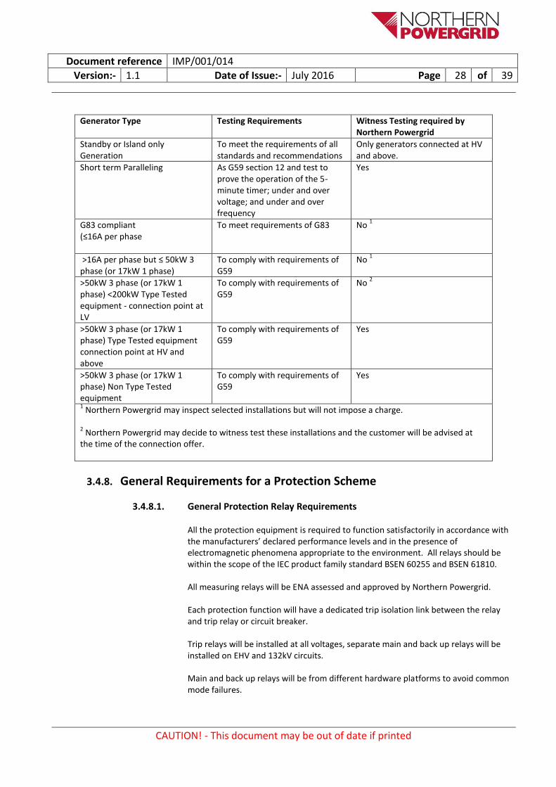
The requirements for witness testing a generator’s installation are shown in the table below, any additional witness testing that may be required on non-standard installations should be discussed and agreed with the installer at an early stage in the project.
Document reference IMP/001/014
Version:- 1.1 Date of Issue:- July 2016 Page 28 of 39
CAUTION! - This document may be out of date if printed
Generator Type Testing Requirements Witness Testing required by Northern Powergrid
Standby or Island only Generation
To meet the requirements of all standards and recommendations
Only generators connected at HV and above.
Short term Paralleling As G59 section 12 and test to prove the operation of the 5-minute timer; under and over voltage; and under and over frequency
Yes
G83 compliant (≤16A per phase
To meet requirements of G83 No 1
>16A per phase but ≤ 50kW 3 phase (or 17kW 1 phase)
To comply with requirements of G59
No 1
>50kW 3 phase (or 17kW 1 phase) <200kW Type Tested equipment - connection point at LV
To comply with requirements of G59
No 2
>50kW 3 phase (or 17kW 1 phase) Type Tested equipment connection point at HV and above
To comply with requirements of G59
Yes
>50kW 3 phase (or 17kW 1 phase) Non Type Tested equipment
To comply with requirements of G59
Yes
1 Northern Powergrid may inspect selected installations but will not impose a charge.
2 Northern Powergrid may decide to witness test these installations and the customer will be advised at
the time of the connection offer.
3.4.8. General Requirements for a Protection Scheme
3.4.8.1. General Protection Relay Requirements
All the protection equipment is required to function satisfactorily in accordance with the manufacturers’ declared performance levels and in the presence of electromagnetic phenomena appropriate to the environment. All relays should be within the scope of the IEC product family standard BSEN 60255 and BSEN 61810. All measuring relays will be ENA assessed and approved by Northern Powergrid. Each protection function will have a dedicated trip isolation link between the relay and trip relay or circuit breaker. Trip relays will be installed at all voltages, separate main and back up relays will be installed on EHV and 132kV circuits. Main and back up relays will be from different hardware platforms to avoid common mode failures.
Document reference IMP/001/014
Version:- 1.1 Date of Issue:- July 2016 Page 29 of 39
CAUTION! - This document may be out of date if printed
3.4.8.2. Protection Relay Functionality
Main protection with numeric relays with self monitoring capabilities shall be installed and where functions are combined, with sufficient redundancy such that failure of a single protection relay will not affect the availability of plant. The following list details the protection functions that can be utilised in a single multi-functional relay no other combinations will be used.
Feeder highset overcurrent and compensated earth fault protection.
Feeder overcurrent and compensated earth fault protection incorporating directional, non-directional, highest and standby main protection stages.
Feeder highset overcurrent and balanced earth fault protection.
Feeder backup overcurrent and earth fault protection.
Low frequency stage 1 and stage 2 protection.
Feeder neutral voltage displacement protection stage 1 and stage 2.
Transformer HV 2 stage overcurrent and balanced earth fault protection
Transformer bias differential, HV restricted earth fault, and LV restricted earth fault protection.
Transformer standby earth fault protection stage 1 and stage 2
Transformer LV directional overcurrent, restricted earth fault and overcurrent protection.
HV feeder overcurrent and earth fault protection
Generator interface protection
3.4.8.3. Protection Relay DC Supplies
All dc supplies to protection and control relays will be monitored. The last device in a dc supply spur to protection and control relays will be either a self supervised protection and control relay or a supply supervision relay. Remote indication of the dc supply supervision will be in accordance with DSS/007/003 - Philosophy of Telecontrol Facilities Provided At Substations (TS8).
3.4.8.4. Testing of Protection Relays
Adequate test and isolation facilities will be provided to facilitate all necessary maintenance and testing without the need to remove wired connections. All test facilities will be normally accessible from the front of the panel.
Document reference IMP/001/014
Version:- 1.1 Date of Issue:- July 2016 Page 30 of 39
CAUTION! - This document may be out of date if printed
Sufficient maintenance test points will be provided to allow main protection, back up protection, control and alarm equipment to be tested and maintained using the automatic test equipment. Relay test blocks will be provided. Protection relays will be designed to allow relay or module replacement without the need to remove individual wired connections.
3.4.8.5. Substation Communications
Protection and control relays will have remote data communications facilities appropriate to the type of relay. Relays will have the ability to communicate directly with the RTU to provide analogues, digital indication and controls; DNP3 will be the preferred protocol. The SCADA and remote data communications will be capable of being in service at the same time. The communications will be capable of operating in a normal substation environment under normal operating conditions, and will continue to operate during fault conditions if this is necessary for the correct operation of the protection and control scheme.
Disturbance recorder installations can be remotely interrogated using suitable software packages.
3.4.8.6. Provision of Voltage and Current Transformers
Current and voltage transformers should comply with the product standards BSEN 60044 The VT supply for protection relays will be supervised for all types of loss of VT input to the protection relay. There will be separate sets of main and back up CTs. The detailed requirements for current transformers as applied to specific protection and metering functions at the different system voltages will be in accordance with the current application. Feeder Overcurrent and Earth Fault Backup Protection on 132kV Ring Systems. For single switch substations, the CTs in the 132kV bus section and the CTs on the HV side of the transformer are summated to enable true feeder current measurement. If a dedicated set of CTs cannot be provided then before being summated, the transformer HV CTs will also feed the two stage HV overcurrent protection.
3.4.8.7. Scheme Diagrams
The following diagrams should be approved by the client engineer prior to construction of the relay panels.
Logic Diagrams

Document reference IMP/001/014
Version:- 1.1 Date of Issue:- July 2016 Page 31 of 39
CAUTION! - This document may be out of date if printed
In general these diagrams will show a schematic of the primary system connections along with the relevant protection and control functions. Four types of diagram are required:
Protection logic diagram – showing the operation of protection to initiate both the local circuit breaker tripping and any intertripping.
Alarms logic diagram – showing local alarms/controls/analogues/indications.
Telecontrol logic diagram – showing remote alarms/controls/analogues/indications.
Auto reclose logic diagram – showing the details of any auto reclose and auto close schemes.
Connections and Protection Diagrams
These diagrams will show a schematic of the primary system connections along with the associated plant information and details of the protection relay panels along with the associated v.t and c.t. connections. A number of these diagrams will be required depending upon the size of the substation.
3.4.8.8. Protection Relay Settings
The setting of protection and control relays will be in accordance with the procedures and formats specified in DSS/007/007 - The Setting of Protection (TS16/17).
3.5. Assumptions
This policy is aimed at ensuring that protection equipment in operation on the network is designed to operate in a safe and effective manner.
3.6. Superseded Documentation
This document supersedes the following documents, all copies of which should be destroyed.
Ref Version Title
DSS/007/001 30 September 1999 The Protection of High Voltage Networks
DSS/007/001 December 2010 Policy for the Protection of Distribution Networks
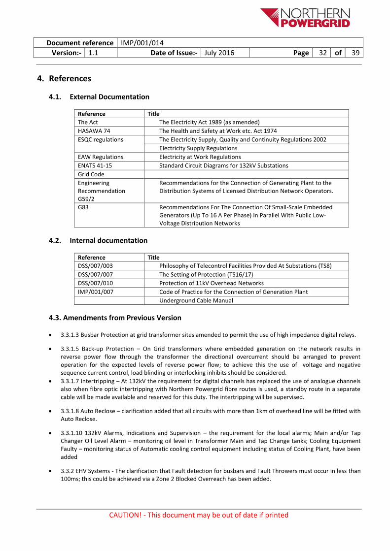
Document reference IMP/001/014
Version:- 1.1 Date of Issue:- July 2016 Page 32 of 39
CAUTION! - This document may be out of date if printed
4. References
4.1. External Documentation
Reference Title
The Act The Electricity Act 1989 (as amended)
HASAWA 74 The Health and Safety at Work etc. Act 1974
ESQC regulations The Electricity Supply, Quality and Continuity Regulations 2002
Electricity Supply Regulations
EAW Regulations Electricity at Work Regulations
ENATS 41-15 Standard Circuit Diagrams for 132kV Substations
Grid Code
Engineering Recommendation G59/2
Recommendations for the Connection of Generating Plant to the Distribution Systems of Licensed Distribution Network Operators.
G83 Recommendations For The Connection Of Small-Scale Embedded Generators (Up To 16 A Per Phase) In Parallel With Public Low-Voltage Distribution Networks
4.2. Internal documentation
Reference Title
DSS/007/003 Philosophy of Telecontrol Facilities Provided At Substations (TS8)
DSS/007/007 The Setting of Protection (TS16/17)
DSS/007/010 Protection of 11kV Overhead Networks
IMP/001/007 Code of Practice for the Connection of Generation Plant
Underground Cable Manual
4.3. Amendments from Previous Version
3.3.1.3 Busbar Protection at grid transformer sites amended to permit the use of high impedance digital relays.
3.3.1.5 Back-up Protection – On Grid transformers where embedded generation on the network results in reverse power flow through the transformer the directional overcurrent should be arranged to prevent operation for the expected levels of reverse power flow; to achieve this the use of voltage and negative sequence current control, load blinding or interlocking inhibits should be considered.
3.3.1.7 Intertripping – At 132kV the requirement for digital channels has replaced the use of analogue channels also when fibre optic intertripping with Northern Powergrid fibre routes is used, a standby route in a separate cable will be made available and reserved for this duty. The intertripping will be supervised.
3.3.1.8 Auto Reclose – clarification added that all circuits with more than 1km of overhead line will be fitted with Auto Reclose.
3.3.1.10 132kV Alarms, Indications and Supervision – the requirement for the local alarms; Main and/or Tap Changer Oil Level Alarm – monitoring oil level in Transformer Main and Tap Change tanks; Cooling Equipment Faulty – monitoring status of Automatic cooling control equipment including status of Cooling Plant, have been added
3.3.2 EHV Systems - The clarification that Fault detection for busbars and Fault Throwers must occur in less than 100ms; this could be achieved via a Zone 2 Blocked Overreach has been added.
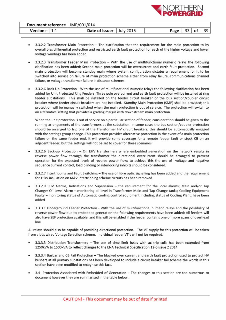
Document reference IMP/001/014
Version:- 1.1 Date of Issue:- July 2016 Page 33 of 39
CAUTION! - This document may be out of date if printed
3.3.2.2 Transformer Main Protection – The clarification that the requirement for the main protection to by overall bias differential protection and restricted earth fault protection for each of the higher voltage and lower voltage windings has been added
3.3.2.3 Transformer Feeder Main Protection – With the use of multifunctional numeric relays the following clarification has been added; Second main protection will be overcurrent and earth fault protection. Second main protection will become standby main where system configuration dictates a requirement for it to be switched into service on failure of main protection scheme either from relay failure, communications channel failure, or voltage transformer failure in distance schemes
3.3.2.6 Back Up Protection - With the use of multifunctional numeric relays the following clarification has been added for Unit Protected Ring Feeders; Three pole overcurrent and earth fault protection will be installed at ring feeder substations. This shall be installed on the feeder circuit breaker or the bus section/coupler circuit breaker where feeder circuit breakers are not installed. Standby Main Protection (SMP) shall be provided; this protection will be manually switched when the main protection is out of service. The protection will switch to an alternative setting that provides a grading margin with downstream main protection.
When the unit protection is out of service on a particular section of feeder, consideration should be given to the running arrangements of the transformers at the substation. In some cases the bus section/coupler protection should be arranged to trip one of the Transformer HV circuit breakers, this should be automatically engaged with the settings group change. This protection provides alternative protection in the event of a main protection failure on the same feeder end. It will provide some coverage for a remote feeder fault or stuck CB on an adjacent feeder, but the settings will not be set to cover for these scenarios
3.3.2.6 Back-up Protection – On EHV transformers where embedded generation on the network results in reverse power flow through the transformer the directional overcurrent should be arranged to prevent operation for the expected levels of reverse power flow; to achieve this the use of voltage and negative sequence current control, load blinding or interlocking inhibits should be considered.
3.3.2.7 Intertripping and Fault Switching – The use of fibre optic signalling has been added and the requirement for 15kV insulation on 66kV intertripping scheme circuits has been removed.
3.3.2.9 EHV Alarms, Indications and Supervision – the requirement for the local alarms; Main and/or Tap Changer Oil Level Alarm – monitoring oil level in Transformer Main and Tap Change tanks; Cooling Equipment Faulty – monitoring status of Automatic cooling control equipment including status of Cooling Plant, have been added
3.3.3.1 Underground Feeder Protection - With the use of multifunctional numeric relays and the possibility of reverse power flow due to embedded generation the following requirements have been added; All feeders will also have SEF protection available, and this will be enabled if the feeder contains one or more spans of overhead line.
All relays should also be capable of providing directional protection. The VT supply for this protection will be taken from a bus wired Voltage Selection scheme. Individual feeder VT’s will not be required.
3.3.3.3 Distribution Transformers – The use of time limit fuses with ac trip coils has been extended from 1250kVA to 1500kVA to reflect changes to the ENA Technical Specification 12-6 issue 2 2014.
3.3.3.4 Busbar and CB Fail Protection – The blocked over current and earth fault protection used to protect HV busbars at all primary substations has been developed to include a circuit breaker fail scheme the words in this section have been modified to recognise this fact.
3.4 Protection Associated with Embedded of Generation – The changes to this section are too numerous to document however they are summarised in the table below:

Document reference IMP/001/014
Version:- 1.1 Date of Issue:- July 2016 Page 34 of 39
CAUTION! - This document may be out of date if printed
Protection Requirements – Summary Table.
Site Generator Capacity
Site Connection Method
Prevailing Technology
Customer G59
Protection
Northern Powergrid Interface Protection Required
LOM Intertrip Required
PQ Logging and SCADA6
>50kVA <=200kVA
Embedded in Network
Any Yes1 No No No
>200kVA <=5MVA
Embedded in Network
Non Synchronous
Yes No No Yes
>200kVA <=5MVA
Embedded in Network
Synchronous Yes Yes2 No Yes
>200kVA <=5MVA
Direct to Supply Point/ Primary
Any Yes Yes3 No4 Yes
>200kVA <=50MVA
Firm connection to Supply Point/ Primary
Any Yes Yes5 Yes5 Yes
>5MVA <=50MVA
Embedded in Network or Direct to Supply Point/ Primary
Any Yes Yes No4 Yes
>50MVA Any Any Yes Yes Yes Yes
1. Type tested units are allowed for connections less than 200kVA. 2. Sites with a total Generation capacity less than 0.5 x the demand capacity do not require Northern Powergrid
interface protection. 3. For a connection into the first leg from a HV busbar Northern Powergrid interface protection will be fitted 4. LOM Intertrip will be considered where an existing Loss of Mains scheme is available or at the request from a
customer who requires it for their operational requirements. LOM Intertrip will typically just be connected back to the normal feeding primary busbar but dependent upon system islanding risk could extend into the upper voltage network
5. IT from transformer incomers and bus section should be arranged to trip appropriate CBs supplying the customer, alternatively interface protection can be installed.
6. PQ Logging to be permanently installed at all HV and EHV connections.
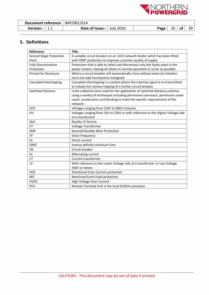
Document reference IMP/001/014
Version:- 1.1 Date of Issue:- July 2016 Page 35 of 39
CAUTION! - This document may be out of date if printed
5. Definitions
Reference Title
Second Stage Protection Point
A suitable circuit breaker on an 11kV network feeder which has been fitted with IDMT protection to improve customer quality of supply
Fully Discriminative Protection
Protection that is able to select and disconnect only the faulty plant in the power system, leaving all others in normal operation in so far as possible.
Primed for Reclosure
Where a circuit breaker will automatically close without external initiation once one side has become energised.
Cascaded Intertripping
Cascaded intertripping is a system where the intertrip signal is re-transmitted to initiate the remote tripping of a further circuit breaker.
Switched Distance Is the collective term used for the application of switched distance schemes using a variety of techniques including permissive overreach, permissive under reach, acceleration and blocking to meet the specific requirements of the network
EHV Voltages ranging from 22kV to 66kV inclusive
HV Voltages ranging from 1kV to 22kV or with reference to the Higher Voltage side of a transformer
QoS Quality of Service
VT Voltage Transformer
SMP Second/Standby Main Protection
VF Voice Frequency
Dc Direct current
IDMT Inverse definite minimum time
CB Circuit breaker
Ac Alternating current
CT Current transformer
LV With reference to the Lower Voltage side of a transformer or Low Voltage 430V or below
DOC Directional Over Current protection
REF Restricted Earth Fault protection
HVOC High Voltage Over Current
RTU Remote Terminal Unit is the local SCADA outstation

Document reference IMP/001/014
Version:- 1.1 Date of Issue:- July 2016 Page 36 of 39
CAUTION! - This document may be out of date if printed
6. Authority for issue
6.1. CDS Assurance
I sign to confirm that I have completed and checked this document and I am satisfied with its content and submit it for approval and authorisation.
Sign Date
Lynn Donald CDS Administrator Lynn Donald 15/07/16
6.2. Author
I sign to confirm that I have completed and checked this document and I am satisfied with its content and submit it for approval and authorisation.
Review Period - This document should be reviewed within the following time period.
Standard CDS review of 3 years
Non Standard Review Period & Reason
Yes Period: Reason:
Sign Date
Jim Paine Protection and Technical Services Manager
Jim Paine 18/02/16
6.3. Technical Assurance
I sign to confirm that I am satisfied with all aspects of the content and preparation of this document and submit it for approval and authorisation.
Sign Date
Andrew Scott Protection Manager (South) Andrew Scott 01/03/16
6.4. Approval
Approval is granted for publication of this document.
Sign Date
Mark Nicholson Head of System Strategy Mark Nicholson 22/02/16
6.5. Authorisation
Authorisation is granted for publication of this document.
Sign Date
Mark Drye M. Nicholson (under delegations of authority)
Director of Asset Management Mark Nicholson 05/04/16

Document reference IMP/001/014
Version:- 1.1 Date of Issue:- July 2016 Page 37 of 39
CAUTION! - This document may be out of date if printed
Appendix 1 - Application of intertripping to provide Loss of Mains protection
Requirement
When considering the functional requirements and design of a Loss of Mains (LoM) intertripping scheme there is a need to make sure that the complexity of the scheme isn’t such that the risks of a) mal operation or b) constraining generation off due to communications unavailability are disproportionate to the risks that the LoM scheme is seeking to address.
Whilst the complexity of each LoM intertripping scheme needs to be considered in order to limit the risk of a potential mal operation, it is proposed to limit the range of scenarios that need to be considered as being credible.
A LoM intertripping scheme should be designed to cater for:
Every combination of a planned outage followed by a fault that could lead to a credible scenario where the generator supports an islanded part of the network. (Note 1, 2). It is considered credible that a generator could support an islanded part of the network if the export from the generator is more than half the minimum load on the network.
The combinations of circuit breaker positions (for withdrawable circuit breakers) and circuit breaker isolators (for non withdrawable circuit breakers) and other isolators that could interrupt the electrical connectivity between the potential islanded network and the total system (Note 3).
Notes
1. This is intended to cater for an typical n-2 scenario rather than a double fault scenario on the basis that it may be appropriate to consider the loading levels during the planned outage such that the load criteria was satisfied.
2. In a meshed system where there are more than two infeeds to a site, it is considered not credible for a situation to arise where three or more circuits were out of service and therefore the LoM scheme wouldn’t need to detect such a situation.
3. Some substations comprise ‘ring’ busbars with isolators between each circuit breaker. In such situations there are two parallel paths round the ring, and it is reasonable to assume that the probability of both isolators being open, without Network Management being aware of the situation, is remote. These status of these isolators do not therefore need to be included in the LoM scheme

Document reference IMP/001/014
Version:- 1.1 Date of Issue:- July 2016 Page 38 of 39
CAUTION! - This document may be out of date if printed
Appendix 2 - Additional guidance Notes
i For primary circuits with no continuous earth return conductor (which is the usual case), the earth fault feature of the distance protection will be restricted to zone 1 measurement. A quadilateral earth fault characteristic will be used by the distance protection.
Distance protection will use the loss of load zone 2 acceleration feature where practicable on ring feeder systems.
All systems of distance protection will use switch on to fault logic.
Where a ring system is run with normally open points, the distance protection at these points will be provided with a zone 1 extension feature to reach into the remote end zone to ensure fast clearance of end zone faults. This zone 1 extension will be switchable both locally and via telecontrol using a telecontrol switching relay to reset the protection to a plain zone 1 reach prior to the normally open point being closed.
Further distance protection features may be required for particular ring systems. Specific details can be found in the appropriate technical design manual for that ring system.
ii When the feeder main protection zone excludes the 132kV circuit breaker due to the position of its associated current
transformers; the 132kV busbar protection or mesh corner protection will be arranged to initiate the feeder intertripping or acceleration.
iii This protection provides alternative protection in the event of a main protection failure on the same feeder end, and
provides protection in the event of an uncleared remote fault on another feeder due to a stuck circuit breaker situation complementary to the zone 3 reach on the distance protection.
iv The busbar protection and the feeder back up protection will lock out reclosure.
The auto reclosure associated with the grid transformer is initiated by either the intertrip receive trip (auto reset) relay, the resetting of the HV trip relay mesh corner, or the directional overcurrent relay dependant on scheme. The line voltage is monitored through the LV VT and needs to be present before the close command is given. Operation of either the HV transformer trip relay, transformer back up protection, standby earth fault protection or the winding temperature trip relay will inhibit the auto reclose cycle.
v On ring feeder systems zone three is arranged to limit disruption of supplies in the event of a circuit breaker failing to
open for a fault
vi For primary circuits with no continuous earth return conductor (which is the usual case), the earth fault feature of the
distance protection will be restricted to zone 1 measurement. A quadilateral earth fault characteristic will be used by the distance protection.
Distance protection will use the loss of load zone 2 acceleration feature where practicable on ring feeder systems.
All systems of distance protection will use switch on to fault logic.
Where a ring system is run with normally open points, the distance protection at these points will be provided with a zone 1 extension feature to reach into the remote end zone to ensure fast clearance of end zone faults. This zone 1 extension will be switchable both locally and via telecontrol using a telecontrol switching relay to reset the protection to a plain zone 1 reach prior to the normally open point being closed.

Document reference IMP/001/014
Version:- 1.1 Date of Issue:- July 2016 Page 39 of 39
CAUTION! - This document may be out of date if printed
Further distance protection features may be required for particular ring systems. Specific detail can be found in the appropriate technical design manual for that ring system.
vii
Intertripping schemes that contain an unusual mixture of pilot wire intertripping, fault throwing switches, directional overcurrent protection, and neutral displacement protection will be checked to verify that they comply with the overall clearance times specified in section 3.3.3.2.
viii The exceptions to these interconnected systems are sections of busbars and small zones at primary substations.


![[014] ass 014 [1881]](https://img.pdfslide.us/doc/110x75/5695d38d1a28ab9b029e5607/014-ass-014-1881.jpg)