Embed Size (px)
Citation preview
CONDUCTED RF EQUIPMENT POWER AMPLIFIERS
Immunity to harmonics, inter-harmonics and
www.ametek-cts.com
Immunity to harmonics, inter-harmonics and voltage ripples present in public power grids
IEC 61000-4-13 / -16 / -19
Daniel Spira – Product manager
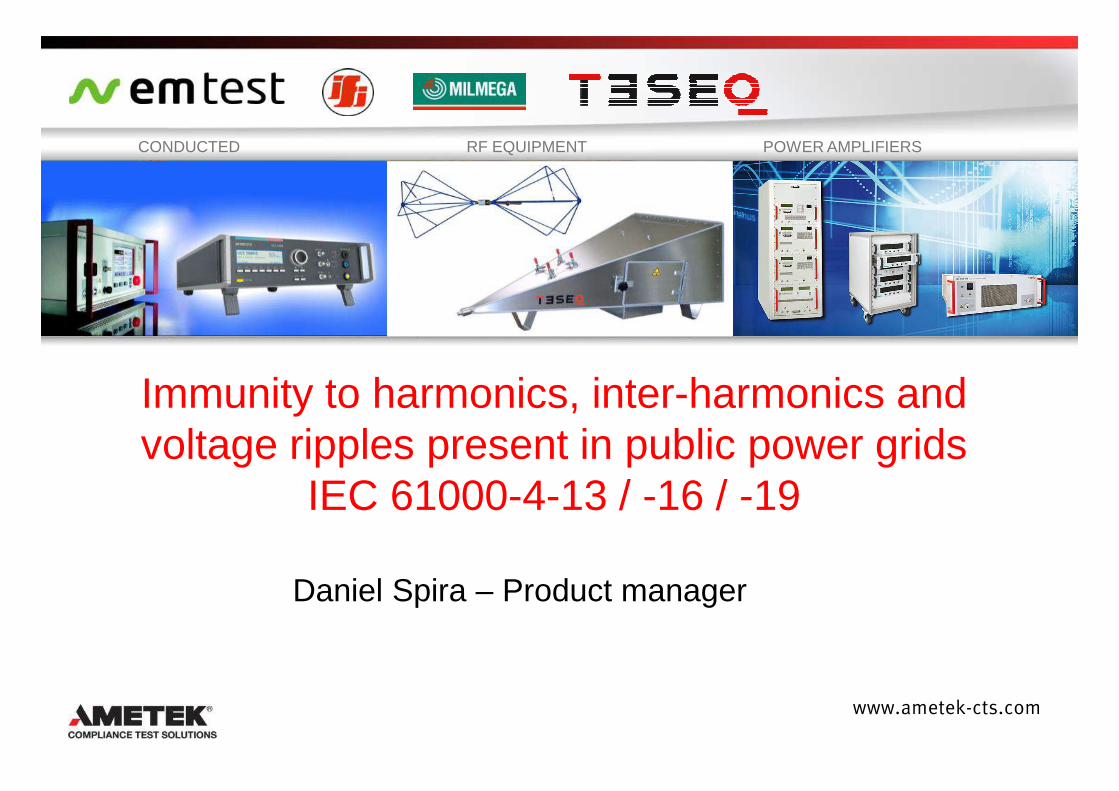
Introduction
Harmonics and interharmonics immunity –IEC 61000-4-13
Common mode conducted immunity 0 to 150 kHz –IEC 61000-4-16
AgendaAgenda
2www.ametek-cts.com
IEC 61000-4-16
Differential mode conducted immunity 2 to 150 kHz –IEC 61000-4-19
Outlook – which changes lay ahead?
Introduction Harmonics and interharmonics immunity –
IEC 61000-4-13
Common mode conducted immunity 0 to 150 kHz –IEC 61000-4-16
AgendaAgenda
3www.ametek-cts.com
IEC 61000-4-16
Differential mode conducted immunity 2 to 150 kHz –IEC 61000-4-19
Outlook – which changes lay ahead?
> Ametek CTS> Ametek CTS
4www.ametek-cts.com
Over 50 years of EMC experience
300 employees in 9 countries on 3 continents
4 production facilities : CH / D / UK / USA
8 service & support centers
www.ametek-cts.com
> Speaker information > Speaker information –– Daniel Daniel SpiraSpira
Master of Science in Microengineering, EPFL, Lausanne
Quality engineer, Swatch Group - EM Microelectronic
5www.ametek-cts.com
R&D and Project Manager, Leister Process Technologies
Master of Business Administration, China Europe International Business School, Shanghai
Product Manager Conducted EMC, TESEQ AG / AMETEK CTSMember of IEC National Comittee CES/TK 77A
Introduction
Harmonics and interharmonics immunity –IEC 61000-4-13
Common mode conducted immunity 0 to 150 kHz –IEC 61000-4-16
AgendaAgenda
6www.ametek-cts.com
IEC 61000-4-16
Differential mode conducted immunity 2 to 150 kHz –IEC 61000-4-19
Outlook – which changes lay ahead?
IEC 61000IEC 61000--44--1313
Status :Status :
Ed. 1.1 : 2009-07 CSV
AMD1 : 2009-05
Ed. 1.0 : 2002-03
7www.ametek-cts.com
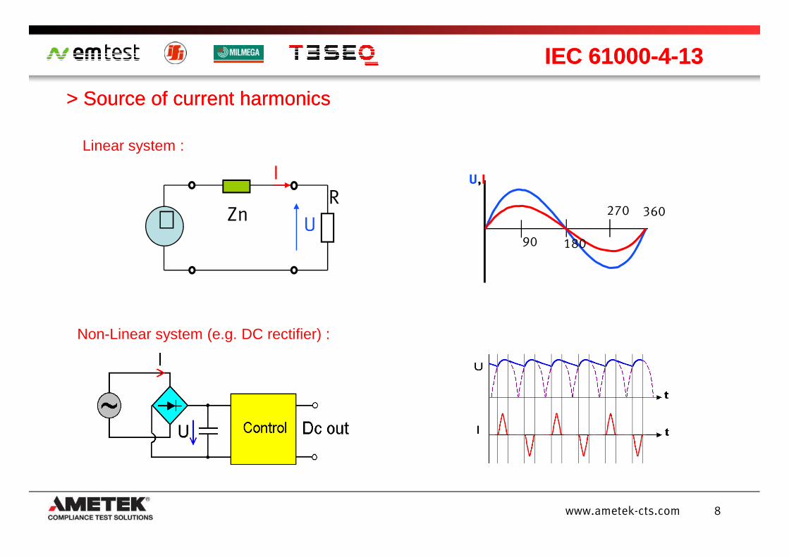
> Source > Source ofof currentcurrent harmonicsharmonics
IEC 61000IEC 61000--44--1313
Linear system :
90 180
270 360
U,I
IZn
R
U
I
∼
8www.ametek-cts.com
Non-Linear system (e.g. DC rectifier) :
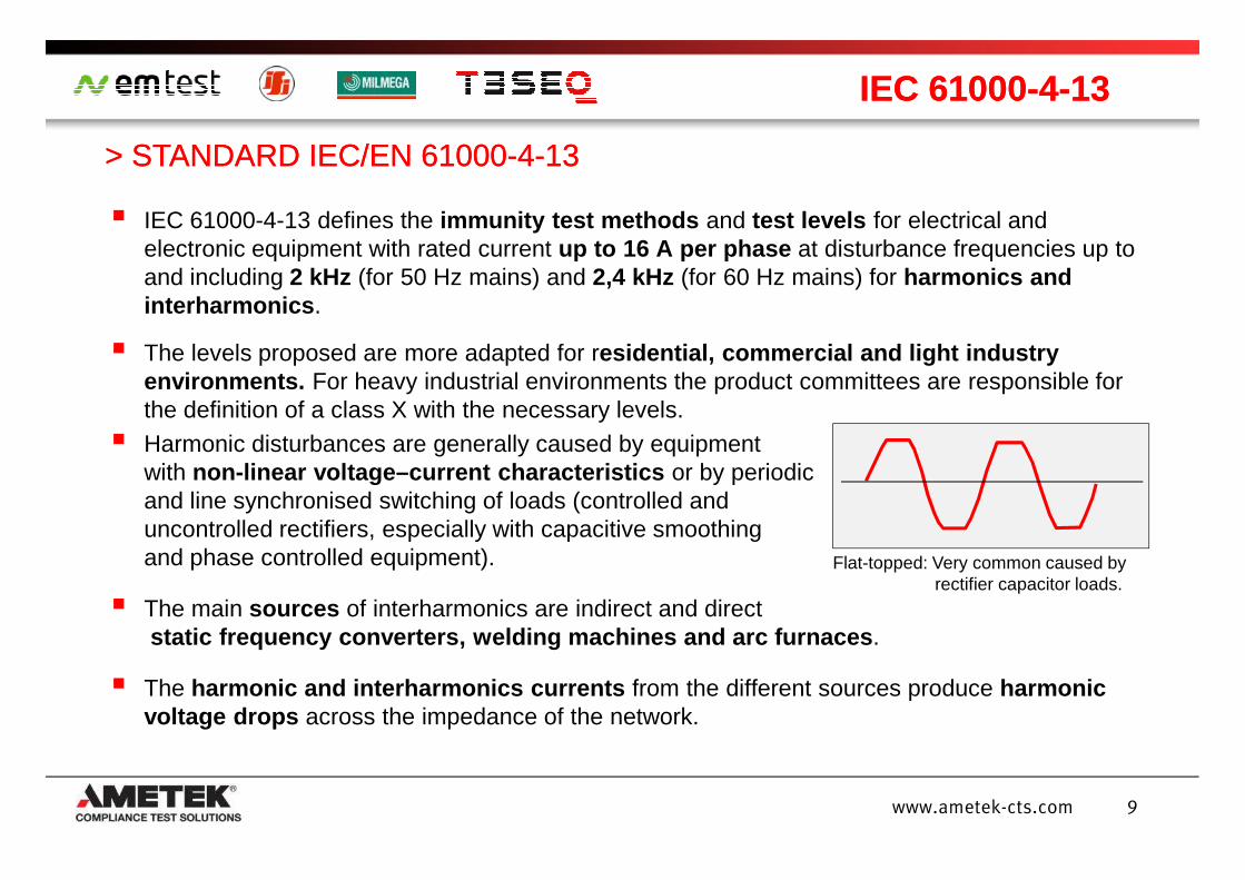
IEC 61000-4-13 defines the immunity test methods and test levels for electrical and electronic equipment with rated current up to 16 A per phase at disturbance frequencies up to and including 2 kHz (for 50 Hz mains) and 2,4 kHz (for 60 Hz mains) for harmonics and interharmonics .
The levels proposed are more adapted for residential, commercial and light industry environments. For heavy industrial environments the product committees are responsible for the definition of a class X with the necessary levels.
Harmonic disturbances are generally caused by equipment
> STANDARD IEC/EN 61000> STANDARD IEC/EN 61000--44--1313
IEC 61000IEC 61000--44--1313
9www.ametek-cts.com
Harmonic disturbances are generally caused by equipment with non-linear voltage–current characteristics or by periodicand line synchronised switching of loads (controlled anduncontrolled rectifiers, especially with capacitive smoothingand phase controlled equipment).
The main sources of interharmonics are indirect and directstatic frequency converters, welding machines and a rc furnaces .
The harmonic and interharmonics currents from the different sources produce harmonic voltage drops across the impedance of the network.
Flat-topped: Very common caused by rectifier capacitor loads.
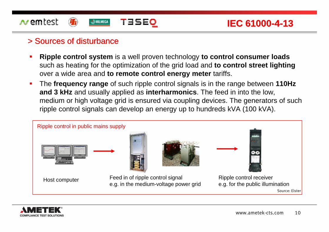
Ripple control system is a well proven technology to control consumer loads such as heating for the optimization of the grid load and to control street lighting over a wide area and to remote control energy meter tariffs.
The frequency range of such ripple control signals is in the range between 110Hz and 3 kHz and usually applied as interharmonics . The feed in into the low, medium or high voltage grid is ensured via coupling devices. The generators of such ripple control signals can develop an energy up to hundreds kVA (100 kVA).
> > SourcesSources ofof disturbancedisturbance
IEC 61000IEC 61000--44--1313
10www.ametek-cts.com
Feed in of ripple control signal e.g. in the medium-voltage power grid
Host computer Ripple control receiver e.g. for the public illumination
Source: Elster
Ripple control in public mains supply
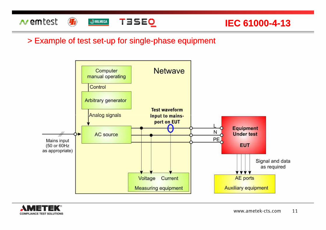
> > Example of test setExample of test set--up for singleup for single--phase equipmentphase equipment
IEC 61000IEC 61000--44--1313
11www.ametek-cts.com
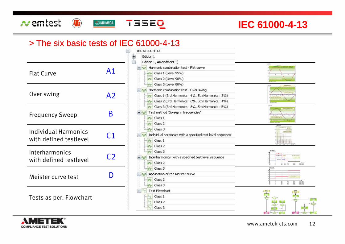
Flat Curve
Over swing
Frequency Sweep
A1
A2
B
> The > The sixsix basicbasic teststests ofof IEC 61000IEC 61000--44--1313
IEC 61000IEC 61000--44--1313
12www.ametek-cts.com
Individual Harmonics with defined testlevel
Interharmonics with defined testlevel
Meister curve test
Tests as per. Flowchart
C1
C2
D
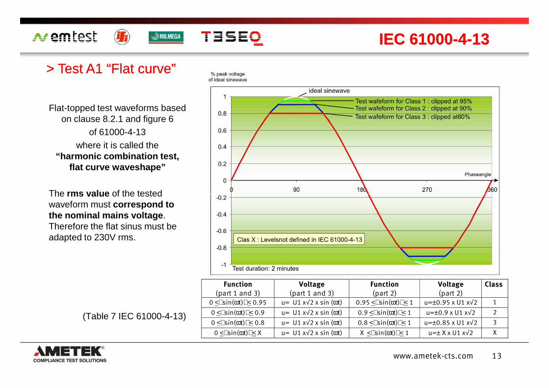
Flat-topped test waveforms based on clause 8.2.1 and figure 6
of 61000-4-13 where it is called the
“harmonic combination test, flat curve waveshape”
The rms value of the tested
> > Test A1 “Flat Test A1 “Flat curvecurve””
IEC 61000IEC 61000--44--1313
13www.ametek-cts.com
The rms value of the tested waveform must correspond to the nominal mains voltage . Therefore the flat sinus must be adapted to 230V rms.
(Table 7 IEC 61000-4-13)
Function
(part 1 and 3) Voltage
(part 1 and 3) Function
(part 2) Voltage
(part 2) Class
0 <sin(ωt)< 0.95 u= U1 x√2 x sin (ωt) 0.95 <sin(ωt)< 1 u=±0.95 x U1 x√2 1
0 <sin(ωt)< 0.9 u= U1 x√2 x sin (ωt) 0.9 <sin(ωt)< 1 u=±0.9 x U1 x√2 2
0 <sin(ωt)< 0.8 u= U1 x√2 x sin (ωt) 0.8 <sin(ωt)< 1 u=±0.85 x U1 x√2 3
0 <sin(ωt)< X u= U1 x√2 x sin (ωt) X <sin(ωt)< 1 u=± X x U1 x√2 X
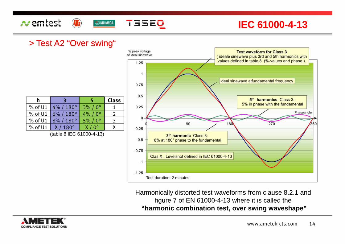
h 3 5 Class
% of U1 4% / 180° 3% / 0° 1
% of U1 6% / 180° 4% / 0° 2
% of U1 8% / 180° 5% / 0° 3
> > Test A2 “Over swing“ Test A2 “Over swing“
IEC 61000IEC 61000--44--1313
14www.ametek-cts.com
Harmonically distorted test waveforms from clause 8.2.1 and figure 7 of EN 61000-4-13 where it is called the
“harmonic combination test, over swing waveshape”
% of U1 8% / 180° 5% / 0° 3
% of U1 X / 180° X / 0° X (table 8 IEC 61000-4-13)
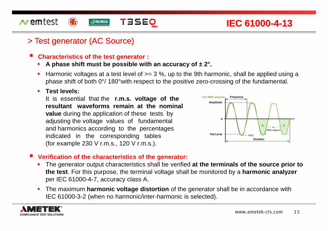
Characteristics of the test generator : A phase shift must be possible with an accuracy of ± 2°.
Harmonic voltages at a test level of >= 3 %, up to the 9th harmonic, shall be applied using a phase shift of both 0°/ 180°with respect to the positive zero-crossing of the fundamental.
Test levels:It is essential that the r.m.s. voltage of the resultant waveforms remain at the nominal value during the application of these tests by
> Test > Test generatorgenerator (AC Source)(AC Source)
IEC 61000IEC 61000--44--1313
15www.ametek-cts.com
value during the application of these tests by adjusting the voltage values of fundamental and harmonics according to the percentages indicated in the corresponding tables (for example 230 V r.m.s., 120 V r.m.s.).
Verification of the characteristics of the generato r: The generator output characteristics shall be verified at the terminals of the source prior to
the test . For this purpose, the terminal voltage shall be monitored by a harmonic analyzer per IEC 61000-4-7, accuracy class A.
The maximum harmonic voltage distortion of the generator shall be in accordance with IEC 61000-3-2 (when no harmonic/inter-harmonic is selected).
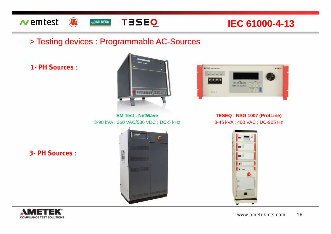
1- PH Sources :
> > TestingTesting devicesdevices : Programmable AC: Programmable AC--SourcesSources
IEC 61000IEC 61000--44--1313
EM Test : NetWave TESEQ : NSG 1007 (ProfLine)
16www.ametek-cts.com
3- PH Sources :
EM Test : NetWave3-90 kVA ; 360 VAC/500 VDC ; DC-5 kHz
TESEQ : NSG 1007 (ProfLine)3-45 kVA ; 400 VAC ; DC-905 Hz
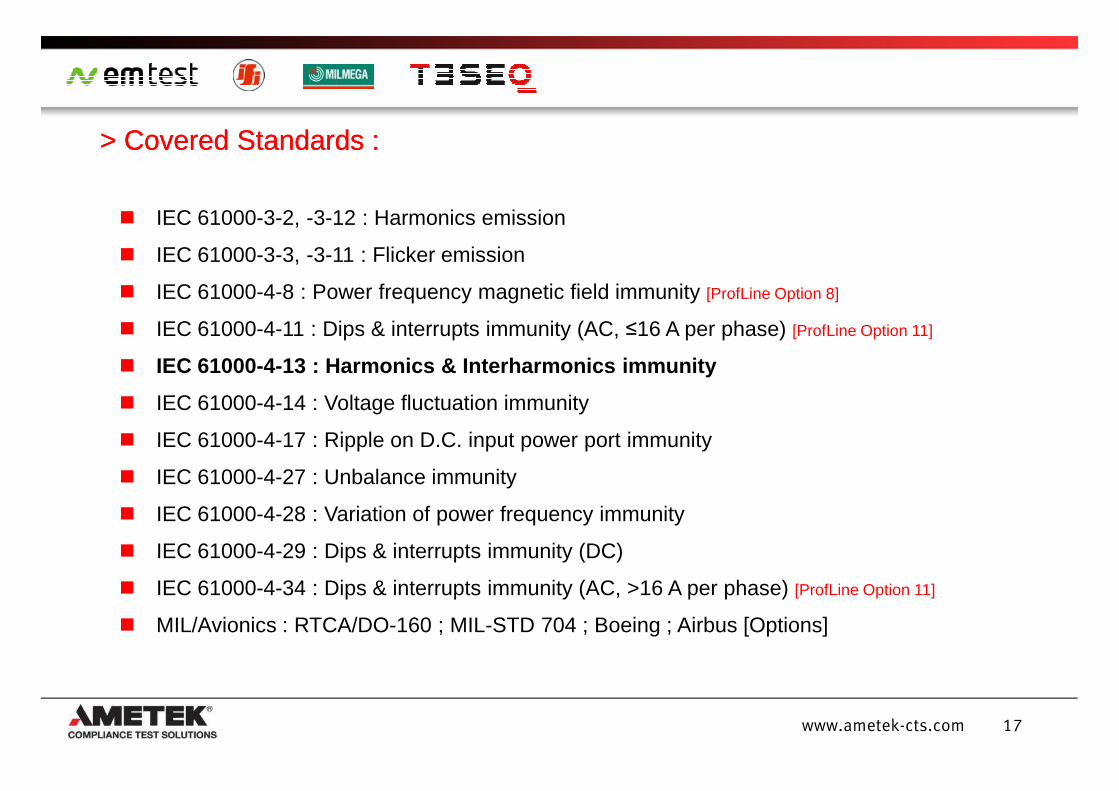
IEC 61000-3-2, -3-12 : Harmonics emission
IEC 61000-3-3, -3-11 : Flicker emission
IEC 61000-4-8 : Power frequency magnetic field immunity [ProfLine Option 8]
IEC 61000-4-11 : Dips & interrupts immunity (AC, ≤16 A per phase) [ProfLine Option 11]
IEC 61000-4-13 : Harmonics & Interharmonics immunity
IEC 61000-4-14 : Voltage fluctuation immunity
> > Covered Standards :Covered Standards :
17www.ametek-cts.com
IEC 61000-4-14 : Voltage fluctuation immunity
IEC 61000-4-17 : Ripple on D.C. input power port immunity
IEC 61000-4-27 : Unbalance immunity
IEC 61000-4-28 : Variation of power frequency immunity
IEC 61000-4-29 : Dips & interrupts immunity (DC)
IEC 61000-4-34 : Dips & interrupts immunity (AC, >16 A per phase) [ProfLine Option 11]
MIL/Avionics : RTCA/DO-160 ; MIL-STD 704 ; Boeing ; Airbus [Options]
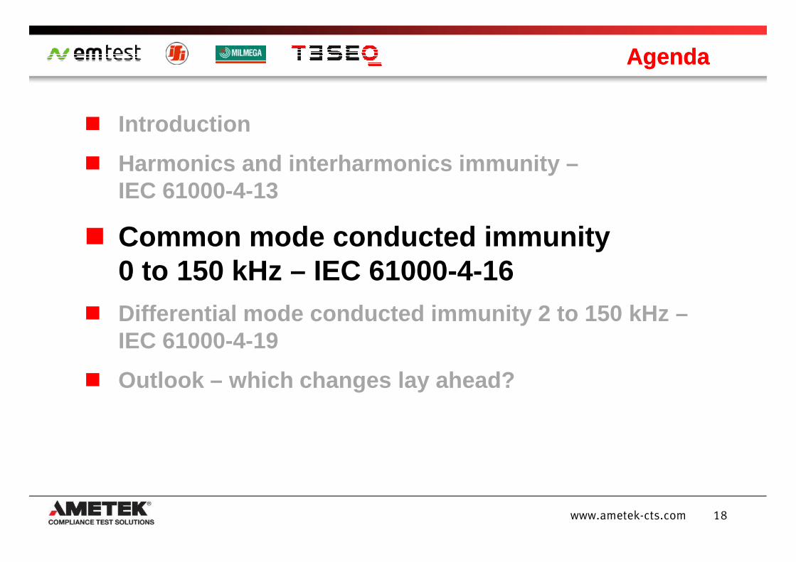
Introduction
Harmonics and interharmonics immunity –IEC 61000-4-13
Common mode conducted immunity 0 to 150 kHz – IEC 61000-4-16
AgendaAgenda
18www.ametek-cts.com
0 to 150 kHz – IEC 61000-4-16 Differential mode conducted immunity 2 to 150 kHz –
IEC 61000-4-19
Outlook – which changes lay ahead?
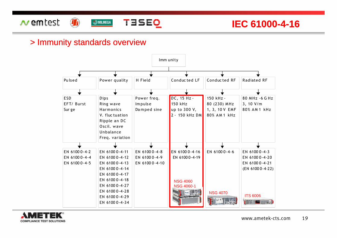
> Immunity standards overview> Immunity standards overview
IEC 61000IEC 61000--44--1616
Imm uni ty
Conduc ted LF
DC, 15 Hz -
150 kHz
up to 300 V,
2 - 150 kHz DM
Radiated RF
80 MHz -6 G Hz
3, 10 V/m
80% A M 1 kHz
Conduc ted RF
150 kHz -
80 (230) MHz
1, 3, 10 V EMF
80% A M 1 kHz
Power quality
Dips
Ring wave
Harmonics
V. fluc tuation
Ripple an DC
ESD
EFT/ Burst
Sur ge
Pu lsed H Field
Power freq.
Im puls e
Da mped sine
19www.ametek-cts.com
EN 6100 0-4-16
EN 6100 0-4-19
EN 6100 0-4-3
EN 6100 0-4-20
EN 6100 0-4-21
(EN 6100 0-4-22)
EN 6100 0-4-6EN 6100 0-4-11
EN 6100 0-4-12
EN 6100 0-4-13
EN 6100 0-4-14
EN 6100 0-4-17
EN 6100 0-4-18
EN 6100 0-4-27
EN 6100 0-4-28
EN 6100 0-4-29
EN 6100 0-4-34
Ripple an DC
Oscil. wave
Unbalance
Freq. variation
EN 6100 0-4-2
EN 6100 0-4-4
EN 6100 0-4-5
EN 6100 0-4-8
EN 6100 0-4-9
EN 6100 0-4-10
NSG 4060 NSG 4060-1
NSG 4070ITS 6006
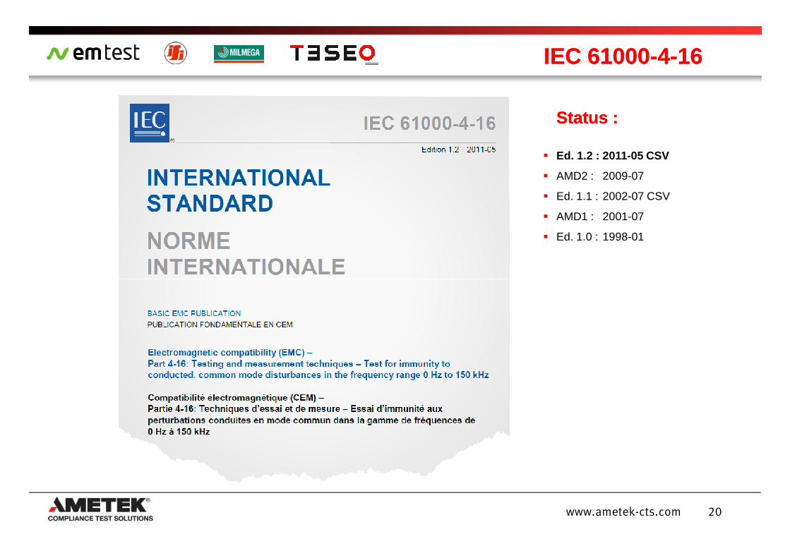
IEC 61000IEC 61000--44--1616
Status :Status :
Ed. 1.2 : 2011-05 CSV
AMD2 : 2009-07
Ed. 1.1 : 2002-07 CSV
AMD1 : 2001-07
Ed. 1.0 : 1998-01
20www.ametek-cts.com
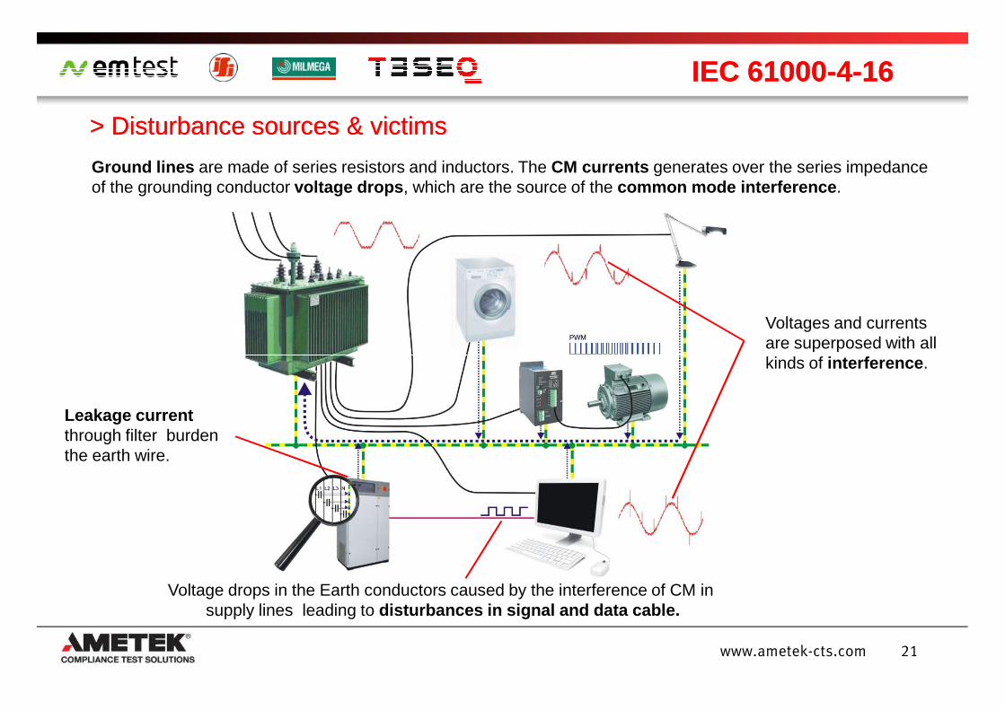
> Disturbance sources > Disturbance sources & victims& victims
IEC 61000IEC 61000--44--1616
Ground lines are made of series resistors and inductors. The CM currents generates over the series impedance of the grounding conductor voltage drops , which are the source of the common mode interference .
Voltages and currents are superposed with all kinds of interference .
21www.ametek-cts.com
Voltage drops in the Earth conductors caused by the interference of CM in supply lines leading to disturbances in signal and data cable.
kinds of interference .
Leakage current through filter burden the earth wire.
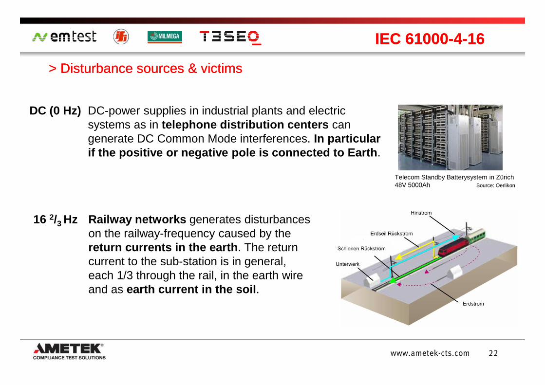
> Disturbance sources & victims> Disturbance sources & victims
IEC 61000IEC 61000--44--1616
DC (0 Hz) DC-power supplies in industrial plants and electric systems as in telephone distribution centers can generate DC Common Mode interferences. In particular if the positive or negative pole is connected to Ea rth .
Telecom Standby Batterysystem in Zürich48V 5000Ah Source: Oerlikon
22www.ametek-cts.com
16 2/3 Hz Railway networks generates disturbances on the railway-frequency caused by the return currents in the earth . The return current to the sub-station is in general, each 1/3 through the rail, in the earth wire and as earth current in the soil .
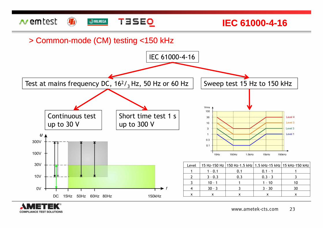
> > CommonCommon--mode (CM) mode (CM) testingtesting <150 kHz<150 kHz
IEC 61000IEC 61000--44--1616
IEC 61000-4-16
Continuous test Short time test 1 s
Sweep test 15 Hz to 150 kHzTest at mains frequency DC, 162/3 Hz, 50 Hz or 60 Hz
23www.ametek-cts.com
Continuous test
up to 30 V
Short time test 1 s
up to 300 V
Level 15 Hz-150 Hz 150 Hz-1.5 kHz 1.5 kHz-15 kHz 15 kHz-150 kHz
1 1 – 0.1 0.1 0.1 – 1 1
2 3 – 0.3 0.3 0.3 – 3 3
3 10 – 1 1 1 – 10 10
4 30 – 3 3 3 – 30 30
x x x x x
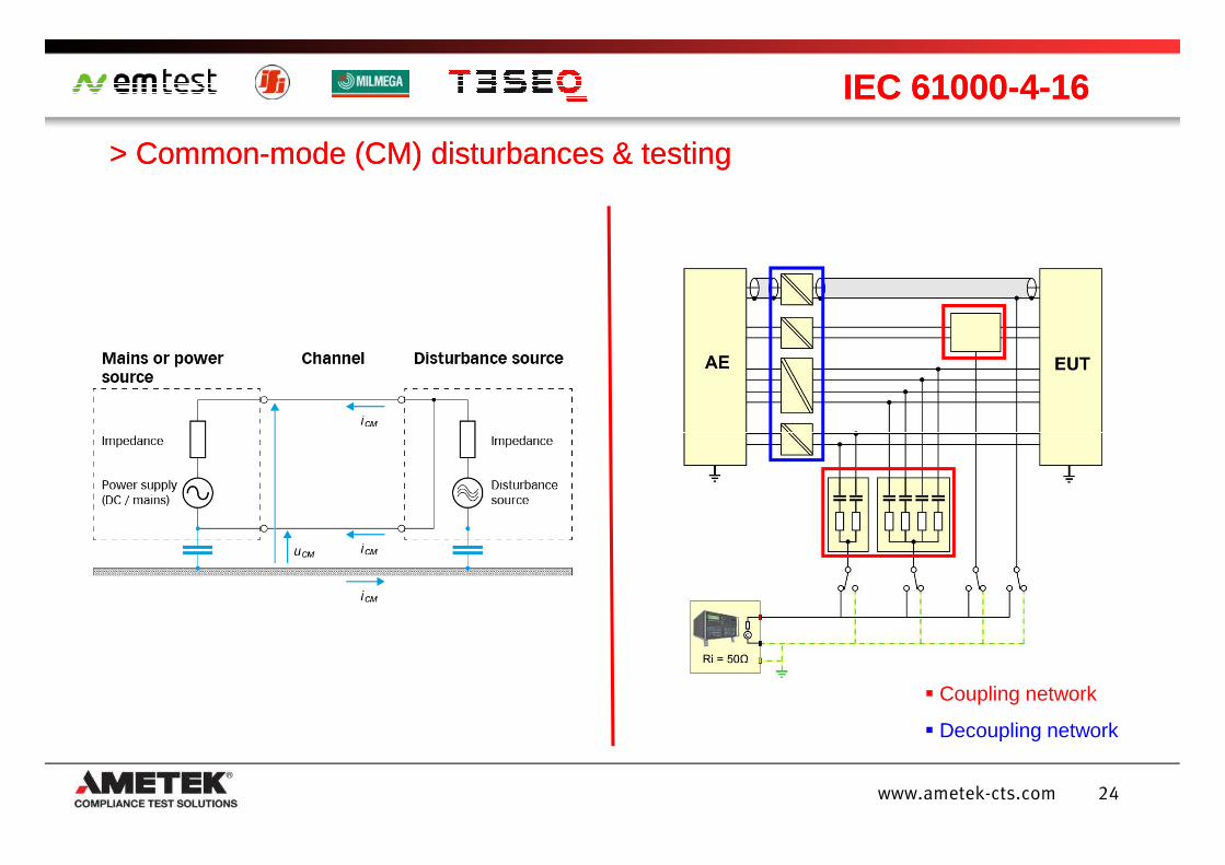
> Common> Common--mode (CM) disturbances & testingmode (CM) disturbances & testing
IEC 61000IEC 61000--44--1616
24www.ametek-cts.com
Coupling network
Decoupling network
> Related IEC & EN standards> Related IEC & EN standards
IEC 61000IEC 61000--44--1616
Disturbance Disturbance sourcesource ::
IEC 61543 Residual Current Protective Device (RCDs) for household and similar use
IEC 60255-22-7 Electrical relays - Part 22-7: Electrical disturbance tests for measuring relays and protection equipment - Power frequency immunity tests
IEC 60533/ Electrical and electronic installations in ships -IEC 60945 Electromagnetic compatibility
25www.ametek-cts.com
IEC 60945 Electromagnetic compatibility
EN 61326-3-1 Electrical equipment for measurement, control and laboratory use - EMC requirements - Part 3-1: Immunity requirements for safety-related systems and for equipment intended to perform safety-related functions (functional safety) - General industrial applications Level 3
IEC 61850-3 Communication networks and systems in substations - Part 3: General requirements:- E.g. Industrial ethernet- Required up to level 4 with 30 V cont. and 300 V for 1 s
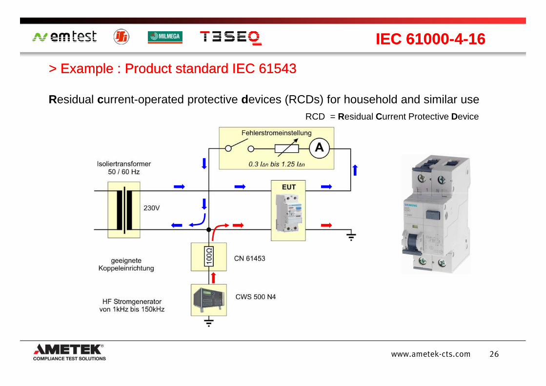
> Example : Product standard IEC 61543> Example : Product standard IEC 61543
IEC 61000IEC 61000--44--1616
Residual current-operated protective devices (RCDs) for household and similar use RCD = Residual Current Protective Device
26www.ametek-cts.com
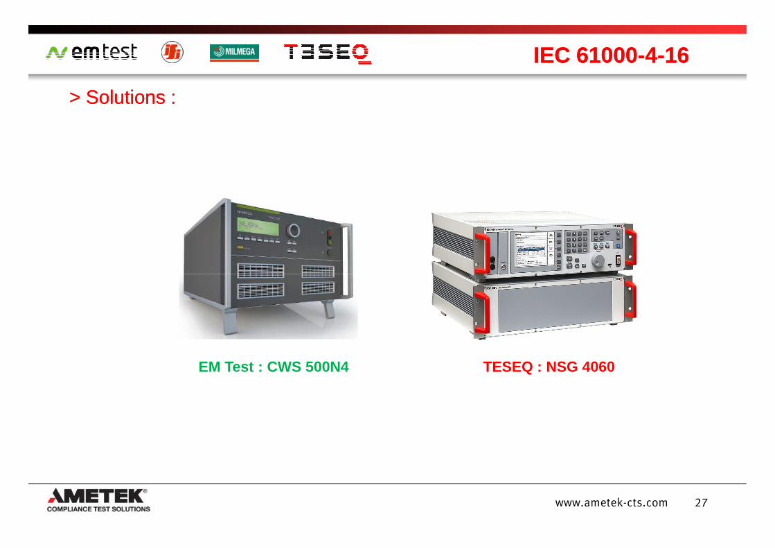
> Solutions :> Solutions :
IEC 61000IEC 61000--44--1616
27www.ametek-cts.com
TESEQ : NSG 4060EM Test : CWS 500N4
Introduction
Harmonics and interharmonics immunity –IEC 61000-4-13
Common mode conducted immunity 0 to 150 kHz –IEC 61000-4-16
AgendaAgenda
28www.ametek-cts.com
IEC 61000-4-16
Differential mode conducted immunity 2 to 150 kHz – IEC 61000 -4-19
Outlook – which changes lay ahead?
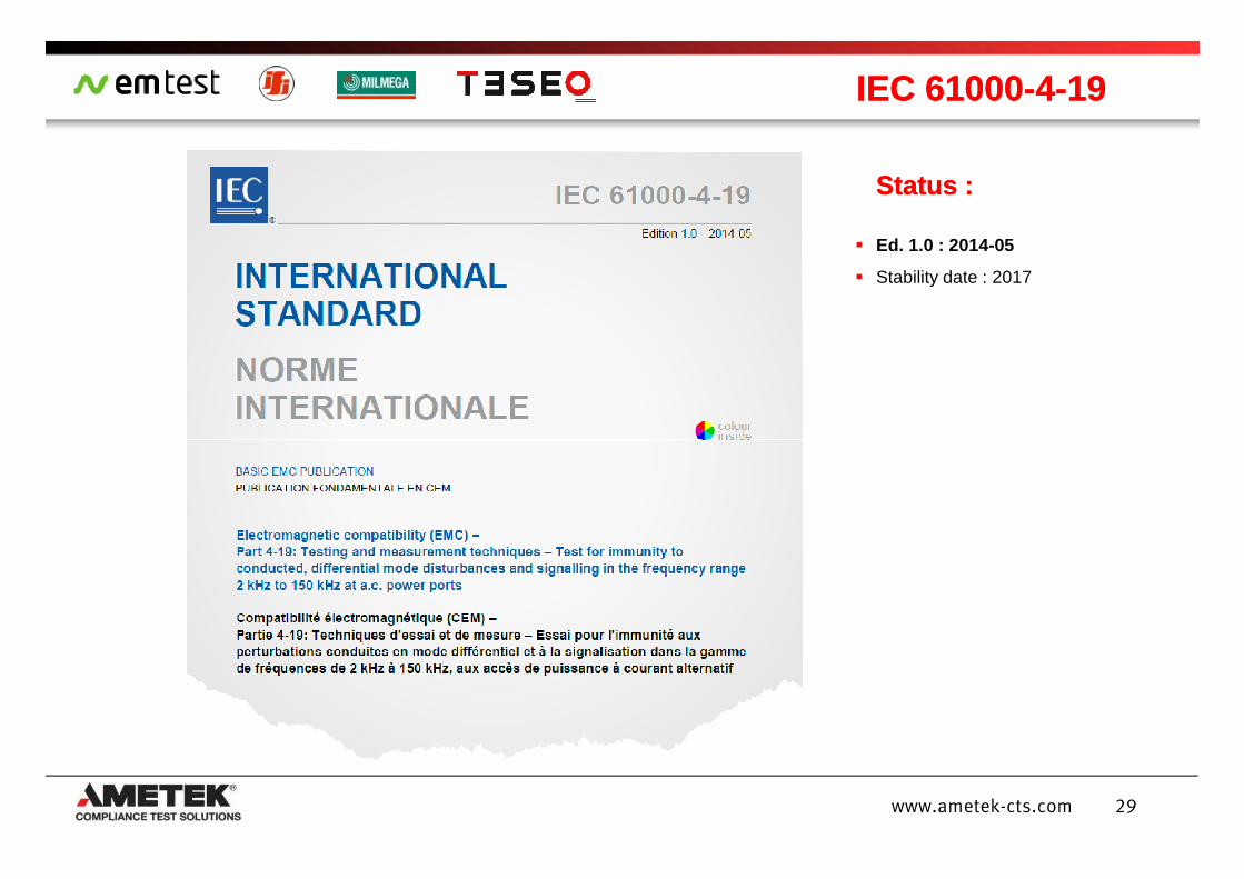
IEC 61000IEC 61000--44--1919
Status :Status :
Ed. 1.0 : 2014-05
Stability date : 2017
29www.ametek-cts.com
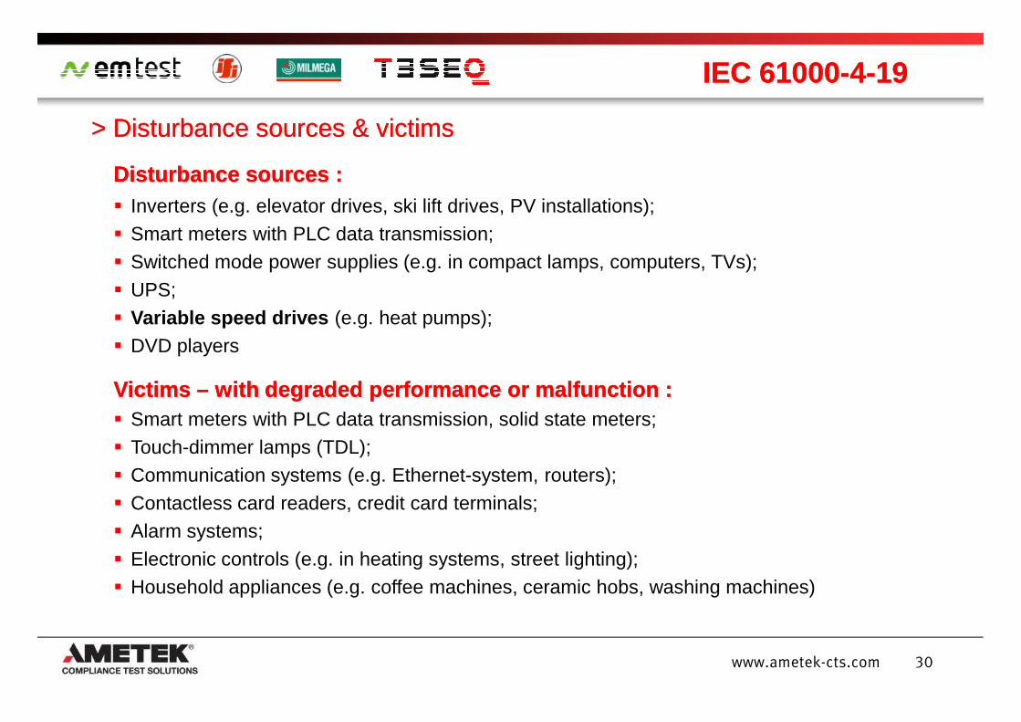
> Disturbance sources & victims> Disturbance sources & victims
IEC 61000IEC 61000--44--1919
DisturbanceDisturbance sourcessources :: Inverters (e.g. elevator drives, ski lift drives, PV installations); Smart meters with PLC data transmission; Switched mode power supplies (e.g. in compact lamps, computers, TVs); UPS; Variable speed drives (e.g. heat pumps); DVD players
30www.ametek-cts.com
VictimsVictims –– withwith degradeddegraded performanceperformance oror malfunctionmalfunction :: Smart meters with PLC data transmission, solid state meters; Touch-dimmer lamps (TDL); Communication systems (e.g. Ethernet-system, routers); Contactless card readers, credit card terminals; Alarm systems; Electronic controls (e.g. in heating systems, street lighting); Household appliances (e.g. coffee machines, ceramic hobs, washing machines)
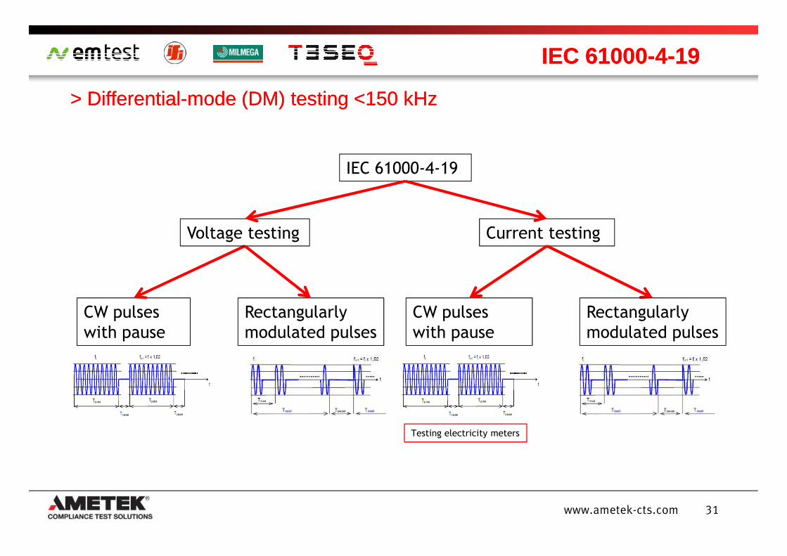
> > DifferentialDifferential--mode (DM) mode (DM) testingtesting <150 kHz<150 kHz
IEC 61000IEC 61000--44--1919
IEC 61000-4-19
Current testingVoltage testing
31www.ametek-cts.com
CW pulses
with pause
Rectangularly
modulated pulses
CW pulses
with pause
Rectangularly
modulated pulses
Testing electricity meters
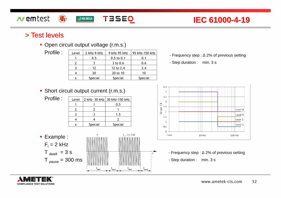
> > Test Test levelslevels
IEC 61000IEC 61000--44--1919
Open circuit output voltage (r.m.s.)Profile :
Short circuit output current (r.m.s.)Profile :
Level 2 kHz-9 kHz 9 kHz-95 kHz 95 kHz-150 kHz
1 0.5 0.5 to 0.1 0.1
2 3 3 to 0.6 0.6
3 12 12 to 2.4 2.4
4 20 20 to 10 10
x Special Special Special
Level 2 kHz- 30 kHz 30 kHz-150 kHz
- Frequency step : ∆ 2% of previous setting
- Step duration : min. 3 s
32www.ametek-cts.com
Profile :
Example : Fi = 2 kHzT dwell = 3 sT pause = 300 ms
Level 2 kHz- 30 kHz 30 kHz-150 kHz
1 1 0.5
2 2 1
3 3 1.5
4 4 2
x Special Special
- Frequency step : ∆ 2% of previous setting
- Step duration : min. 3 s
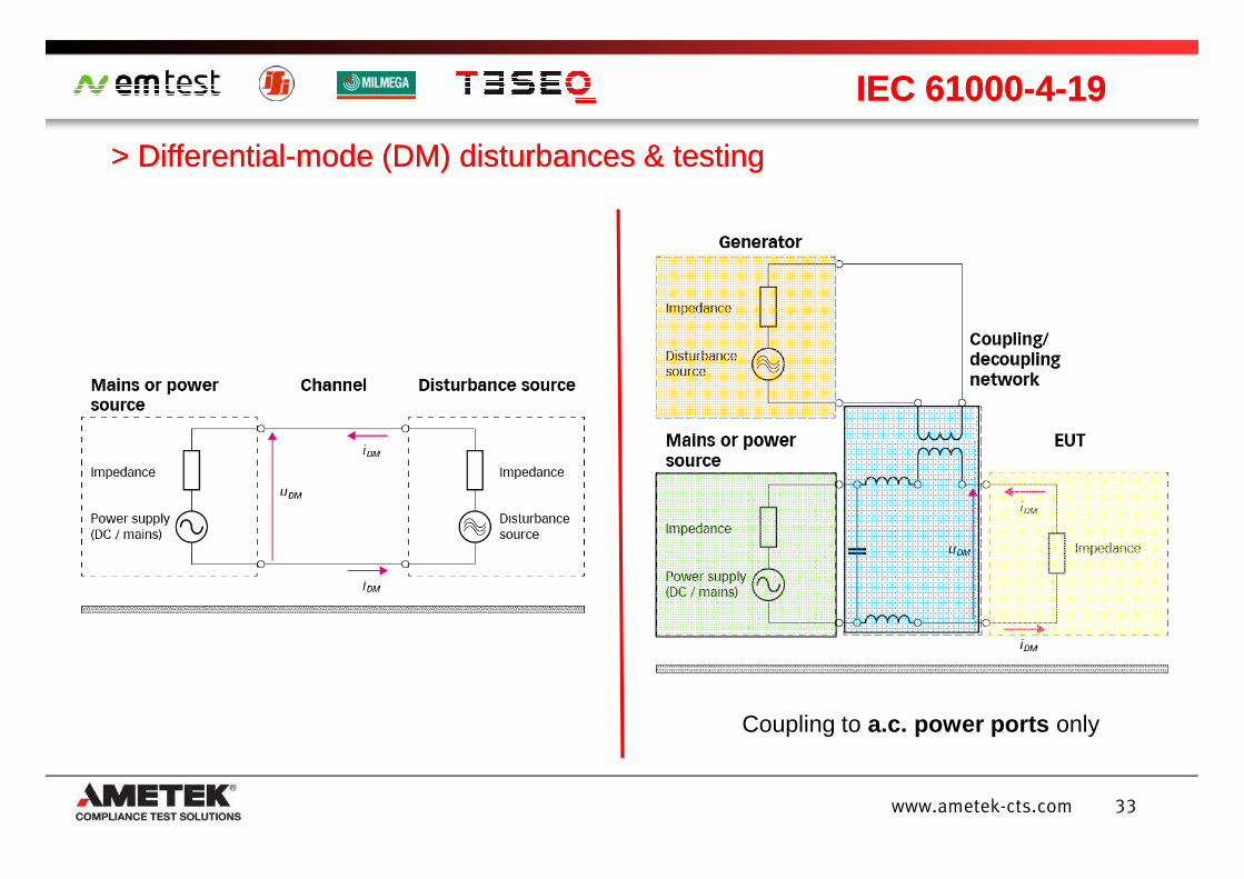
> Differential> Differential--mode (DM) disturbances & testingmode (DM) disturbances & testing
IEC 61000IEC 61000--44--1919
33www.ametek-cts.com
Coupling to a.c. power ports only
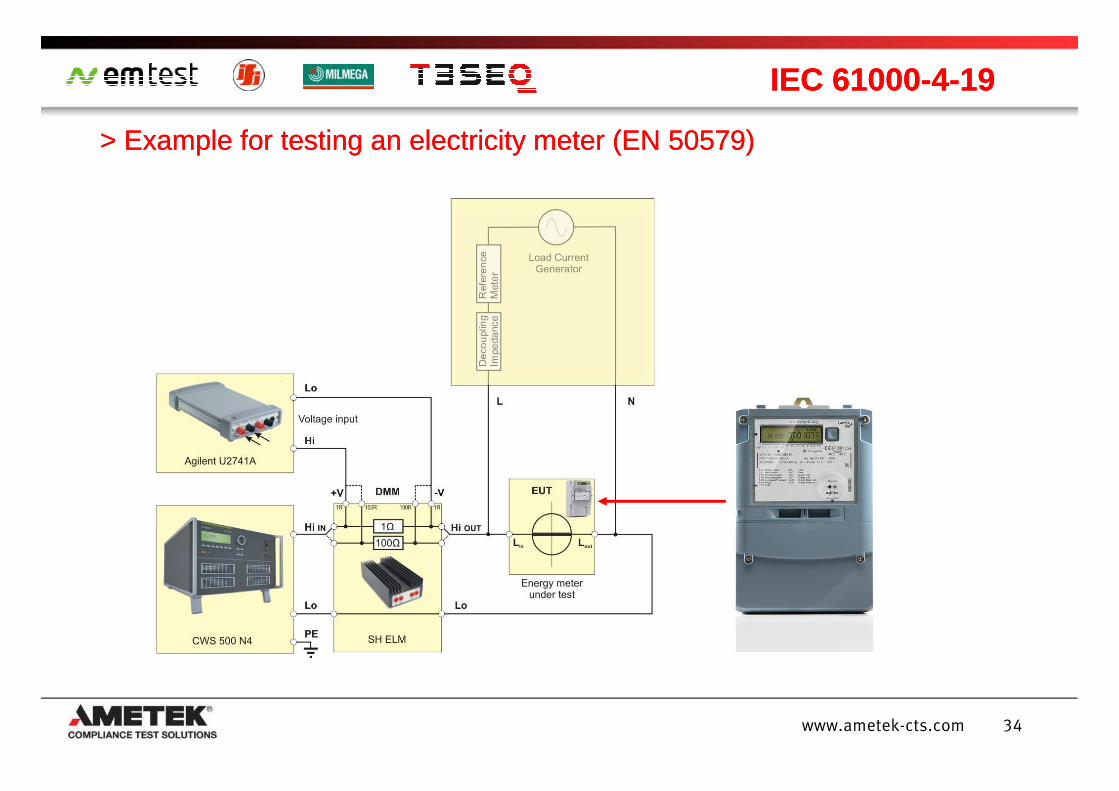
> Example for testing an electricity meter (EN 50579)> Example for testing an electricity meter (EN 50579)
IEC 61000IEC 61000--44--1919
34www.ametek-cts.com
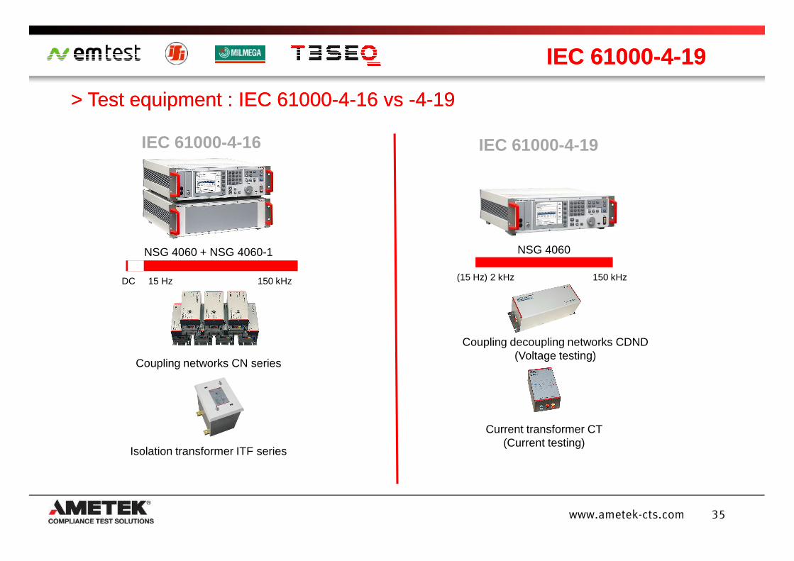
> Test equipment : IEC 61000> Test equipment : IEC 61000--44--16 16 vsvs --44--1919
IEC 61000IEC 61000--44--1919
IEC 61000-4-16
NSG 4060 + NSG 4060-1
DC 15 Hz 150 kHz
IEC 61000-4-19
NSG 4060
(15 Hz) 2 kHz 150 kHz
35www.ametek-cts.com
DC 15 Hz 150 kHz
Coupling networks CN series
Isolation transformer ITF series
(15 Hz) 2 kHz 150 kHz
Coupling decoupling networks CDND(Voltage testing)
Current transformer CT(Current testing)
Introduction
Harmonics and interharmonics immunity –IEC 61000-4-13
Common mode conducted immunity 0 to 150 kHz –IEC 61000-4-16
AgendaAgenda
36www.ametek-cts.com
Differential mode conducted immunity 2 to 150 kHz –IEC 61000-4-19
Outlook – which changes lay ahead?
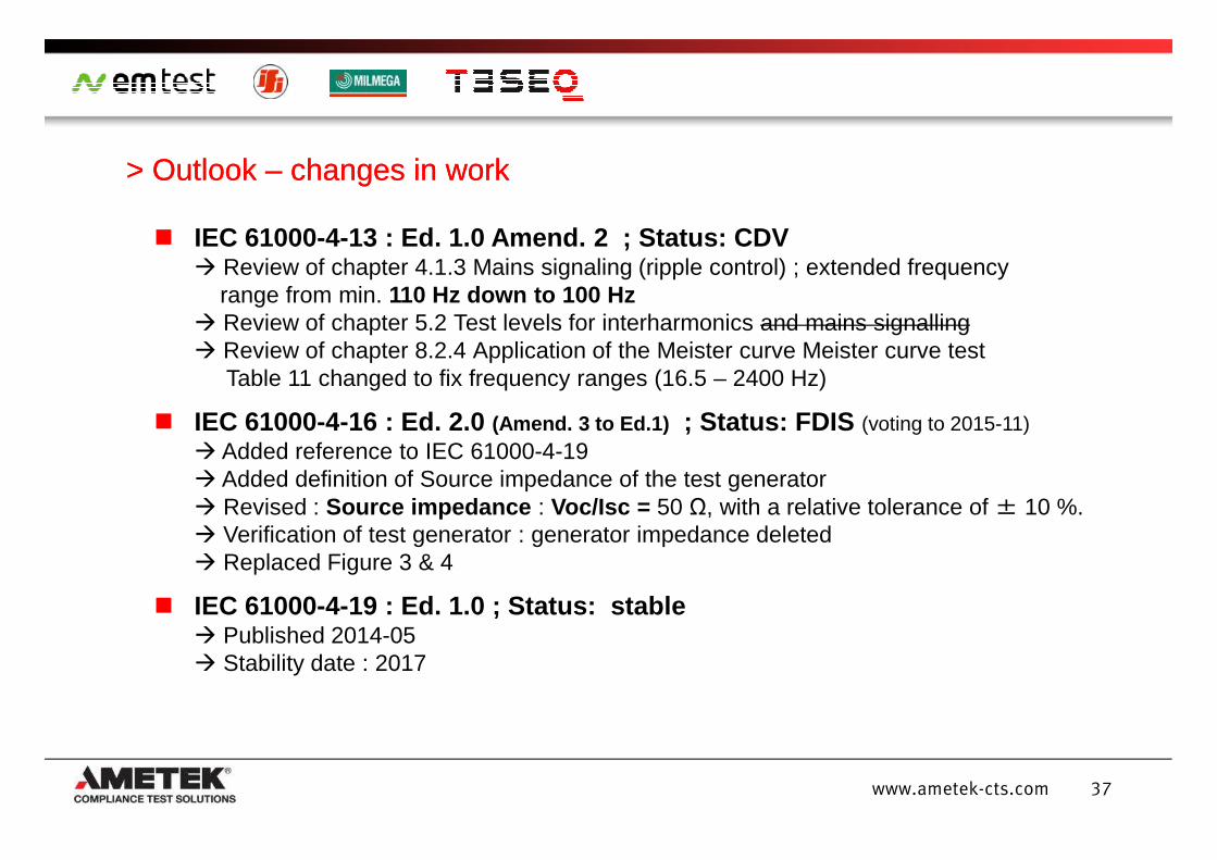
IEC 61000-4-13 : Ed. 1.0 Amend. 2 ; Status: CDV Review of chapter 4.1.3 Mains signaling (ripple control) ; extended frequency
range from min. 110 Hz down to 100 Hz Review of chapter 5.2 Test levels for interharmonics and mains signalling Review of chapter 8.2.4 Application of the Meister curve Meister curve test
Table 11 changed to fix frequency ranges (16.5 – 2400 Hz)
IEC 61000-4-16 : Ed. 2.0 (Amend. 3 to Ed.1) ; Status: FDIS (voting to 2015-11)
> Outlook > Outlook –– changes in workchanges in work
37www.ametek-cts.com
IEC 61000-4-16 : Ed. 2.0 (Amend. 3 to Ed.1) ; Status: FDIS (voting to 2015-11) Added reference to IEC 61000-4-19 Added definition of Source impedance of the test generator Revised : Source impedance : Voc/Isc = 50 Ω, with a relative tolerance of ± 10 %. Verification of test generator : generator impedance deleted Replaced Figure 3 & 4
IEC 61000-4-19 : Ed. 1.0 ; Status: stable Published 2014-05 Stability date : 2017
CONDUCTED RF EQUIPMENT POWER AMPLIFIERS
www.ametek-cts.com
Thank you for your attention