Embed Size (px)
Citation preview

/ft^fr/^Oo I
SS^Lä^&^SS^ NRL Memorandum Report 5384
An Automated Immittance Measuring System for Electroacoustic Transducers
Clementina M. Ruggiero and Theodore A. Henriquez
Underwater Sound Reference Detachment P.O. Box 8337
Orlando, Florida 32856
September 1, 1984
NAVAL RESEARCH LABORATORY \ » \ Washington, D.C.
Approved for public release; distribution unlimited
UNCLASSIFIED SECURITY CLASSIFICATION OF THIS PAGE
REPORT DOCUMENTATION PAGE la. REPORT SECURITY CLASSIFICATION
UNCLASSIFIED
lb. RESTRICTIVE MARKINGS
N/A 2a. SECURITY CLASSIFICATION AUTHORITY
N/A 2b. DECLASSIFICATION / DOWNGRADING SCHEDULE N/A
3. DISTRIBUTION/AVAILABILITY OF. REPORT
Approved for public release; distribution unlimited
4. PERFORMING ORGANIZATION REPORT NUMBER(S)
NRL Memorandum Report 5384 " 5. MONITORING ORGANIZATION REPORT NUMBER(S)
N/A
6a. NAME OF PERFORMING ORGANIZATION
Underwater Sound Ref. Detach. Naval Research Laboratory
6b. OFFICE SYMBOL (If applicable)
Code 5900
7a. NAME OF MONITORING ORGANIZATION
N/A 6c. ADDRESS (City, State, and ZIP Code) P.O. Box 8337 Orlando, Florida 32856
7b. ADDRESS (City, State, and ZIP Code) N/A
8a. NAME OF FUNDING/SPONSORING ORGANIZATION
NAVSEA
8b. OFFICE SYMBOL (If applicable)
63X5
9. PROCUREMENT INSTRUMENT IDENTIFICATION NUMBER
N/A 8c. ADDRESS (City, State, and ZIP Code)
Washington, DC 20362
10. SOURCE OF FUNDING NUMBERS
PROGRAM ELEMENT NO.
24281N
PROJECT NO.
N/A
TASK NO.
S1307AS
WORK UNIT ACCESSION NO.
0584-0 11. TITLE (Include Security Classification)
An Automated Measuring System for Electroacoustic Transducers
12. PERSONAL AUTHOR(S)
RUGGIERO. Clementina M. and HENRIQUEZ. Theodore A. 13a. TYPE OF REPORT Final
113b. TIME COVERED FROM Feb 83 TO Feb 84
14. DATE OF REfORT (Year, Month, Day) -01
15. PAGE COUNT 33
16. SUPPLEMENTARY NOTATION The Sonar Transducer Reliability Improvement Program (STRIP) is sponsored by the Naval Sea Systems Command (SEA63X5). 17 COSATI CODES
FIELD GROUP SUB-GROUP
18. SUBJECT TERMS (Continue on reverse if necessary and identify by block number)
Immittance Transducer Measurements Impedance HP4192 Impedance Analyzer Admittance
19. ABSTRACT (Continue on reverse if necessary and identify by block number)
A fully automated method of obtaining Immittance loops of piezoelectric transducers
has been designed to be utilized in conjunction with the Hewlett-Packard 4192A Impedance
Analyzer. The algorithm determines the frequencies at maximum and minimum immittances,
the series and parallel resonance frequencies, and the resonance and antiresonance
frequencies as well as the mechanical quality factor of the element under test. The
collected data are plotted in the form of either admittance or impedance loops with evenly
spaced points. The program has been implemented successfully as a means to rapidly
obtain the admittance information of various loaded and unloaded transducers and transducer
elements.
20. DISTRIBUTION/AVAILABILITY OF ABSTRACT
©UNCLASSIFIED/UNLIMITED □ SAME AS RPT. D DTIC USERS
21. ABSTRACT SECURITY CLASSIFICATION
UNCLASSIFIED 22a. NAME OF RESPONSIBLE INDIVIDUAL
Clementina M. Ruggiero 22b. TELEPHONE (Include Area Code)
305, 859-5120 22c. OFFICE SYMBOL
Code 5970
DD FORM 1473.84 MAR 83 APR edition may be used until exhausted.
All other editions are obsolete. SECURITY CLASSIFICATION OF THIS PAGE
UNCLASSIFIED

SECURITY CLASSIFICATION OF THIi PAGE
SECURITY CLASSIFICATION OF THif, PAGE

CONTENTS
INTRODUCTION 1
CIRCULAR APPROXIMATION ALGORITHM 3
CRITICAL FREQUENCIES 7
PROGRAM 9
RESTRICTIONS 9
CONCLUSION 10
ACKNOWLEDGMENTS 10
REFERENCES 11
APPENDIX A - Analysis for Applying Equations to Both Immittance Loops 13
APPENDIX B - Program Description and Listing 15
APPENDIX C - Running MICAM 29
iii

AN AUTOMATED MEASURING SYSTEM FOR ELECTROACOUSTIC TRANSDUCERS
INTRODUCTION
The precise measurement of immittance is a valuable tool for the
analysis of electroacoustic transducers and piezoelectric materials.
imnittance is used in the determination of transducer efficiency,
electrical matching, and the tuning and analysis of transducer performance
and of material parameters of active transducer materials. Previous
techniques for immittance measurements involved the use of such devices as
impedance bridges, analog voltmeters, phase meters, and some special analog
devices lüce the vector impedance meter. All of the before mentioned
devices suffer from one or more restrictions; e.g., speed, precision, or
stability.
The HP Model 4192A Digital Network Analyzer is computer controlled
and has the ability to make immittance measurements at high speed with
excellent precision and stability. Combined with the developed circular
approximation algorithm, the measurements can be made with greater
efficiency to provide the maximum amount of information with the minimum
number of data points. This method also allows for fast, accurate
computation of critical points of immittance without knowing the series
(parallel) resonance of the transducer. The optimization of data points is
achieved by the determination of frequencies that will be quasi-uniformly
distributed around the immittance circle as opposed to the "clustering" of
frequencies above and below the frequency of maximum immittance.
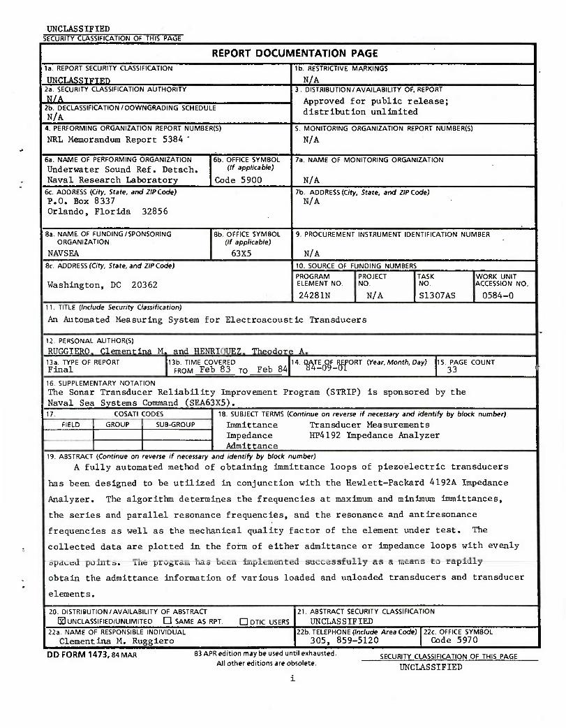
Figure 1 compares an immittance circle defined by a linear sequence of
frequencies with one in which the frequencies are generated from the
circular approximation method. There are two hundred points in the linear
frequency sweep of Pig. la and only fifty points in Pig. lb. This circular
approximation method has been implemented on various piezoelectric
transducers and works exceptionally well in most cases. The timesaving is
greatest when measuring high-Q transducers. Linear-spaced frequency points
appear diluted on the steep slopes of the imaginary part of a high-Q
immittance, as shown in Pig. 2. For low-Q curves the frequency
distribution is more evenly spaced. When the data are presented in the
form of imaginary verses real immittance, the data from high-Q systems are
RUGGIERO AND HENRIQUEZ
4.00
-2.00
-4.00 0.00 2.00 400 6.00 8.00
4.00
2.00
I.«,
-2.00
-4.00
0OOOOOo0
) 0 0
. 0
0 0 0 0 0 0 0
0 0
0 o o o o ° 0.00 2.00 4.00 6.00 8.00
Fig. 1a - Immittance loop showing
the distribution of data
points resulting from a
linear sweep of two
hundred frequency steps.
Fig. 1b - Immittance loop showing the more
uniform distribution of only 50
data points when frequencies
are determined by the circular
approximation method.
Ö z
S Q 2 O
FREQUENCY
Fig. 2 - Distribution of data points for equally spaced frequencies on the imaginary part of the immittance curve for a high-Q system and for a low-Q system.

NRL MEMO REPORT 5384
concentrated near the beginning and end of the immittance circle. For low-
Q systems the data points approach a uniform distribution.
CIRCULAR APPROXIMATION ALGORITHM
The circular approximation method can be applied to admittance and
impedance loops. Because of the similarity of application to impedance and
admittance, and to avoid writing "impedance or admittance", the two
quantities are implied when the term immittance is used in the following
text. The differences between the admittance terms and the impedance terms
will be discussed in the PROGRAM section of this report. Thoughout this
report the word "points" appears many times with various meanings. To
assure clarity three symbols are defined:
o The term "points(f)" refers to a frequency.
o The term "points(c)" refers to the ordered pair
on the the theoretical circle.
o The term "points(i)" refers to the real and
imaginary position on the immittance loop.
The method presented here will be based on the following equation:
f 2 21 r - ui j
tan(G) ■= —- ^. [1] wR
This equation is derived [1] from a simple equivalent circuit of a
piezoelectric resonator, where L is the inductance, w is the angular
frequency, u^ is a resonant frequency (series resonance when measuring
admittance, parallel resonance when measuring impedance), 6 is the phase
angle, and R is the resistance. Cady uses o>0 (angular frequency of zero
crossing) in Eq. (1) instead of «j. But »^ is also an angular frequency at
a zero crossing since a transformation of axes is performed with the
circular approximation method. It is algebraically convenient to write
Eq. (1) in the following form: Given &>, R, and G for three points(f), w*

RUGGIERO AND HENRIQUEZ
and L are determined by applying Cramer's rule [2] to this expression:
2 1 2 d). + - u>Rtan(e) = u> . [2] 1 Li
By using the following eguation
2 2 Lu - La». - a>Rtan(e) = 0, [3]
the angular frequencies (u) are determined as a function of the angle e by
solving the quadratic equation. Equations (2) and (3) are the key
equations used in the circle approximation method and will be referred to
many times in the text of this paper. The argument used for applying
Eqs. (1) through (3) to both impedance and admittance is found in Appendix
A.
The algorithm used in determining the admittance or impedance loops
consists of two major parts. First, the "best fit" circle that
approximates the immittance loop is determined from parameters of the
simple equivalent circuit of a piezoelectric resonator. Secondly, the
circular approximation is then divided into equal arcs that are used to
determine quasi-equally spaced points(i) on the immittance loop.
To determine the "best-fit" circle, one must first identify any three
frequency points(f) on the imaittance loop with the abscissa and ordinate
identified as conductance and susceptance (or resistance and reactance),
respectively. If previous knowledge exists about the transducer to be
measured, these three points(f) are easy to identify. If however, there is
no previous knowledge about the transducer, the program will assist the
user in determining the three points(f).
The HP 4192 Impedance Analyzer measures the real and imaginary parts
of iimnittance at each of these frequency points(f) and the ordered pairs of
data are stored as (xi,yi), where i goes from 1 to 3 corresponding to each
of the three frequency points(f). These ordered pairs are used in the
general form of the equation of a circle:

ML MEMO REPORT 5384
xiD + y±E + p - -[x
±2 + y±
2] C4]
1/2 [—D —El 1 f 2 2 \ —, — and radius -ID + E - 4PJ . [5]
To find D, E, and F, we impose the condition that the coordinates of each
of the given points(ific) satisfy Eq. (4). When these values for D, E, and
P are substituted in Eq. (5), we have the radius and center of the circle
through the given points(i&c). By using the calculated radius and center,
two points(c) located 120 degrees from a fixed initial point(i&c) are found
as shown by the boxes in Fig. 1. The authors have arbitrarily chosen the
fixed point(c) to be the second initial point(i). One may use any initial
point(i) as long as it remains consistent throughout the entire procedure.
In order that this procedure apply both to loaded and unloaded
transducers, a translation of axes is performed on all points(i) used in
Eqs. (2) and (3). The formulas for the translation of axes are:
x = x - x + r and y=y_y [6] toe toe
where (x + r,y ) is the new origin. The ordered pair (x,y ) is the
center of the circle, r is the radius, (x,y) are the old coordinates, and
(xt,yt) are the old coordinates with the new origin. The slope [tan(©)] is
determined by first applying Eqs. (6) to a given point(i). The resistance
R, also found in the Eqs. (2) and (3), is replaced by the diameter or
reciprocal of the diameter of the circle depending on which immittance loop
is chosen. The quantities u^ and L are calculated using Eq. (2) and the
data of two intial points(i) along with information from the circle. With
the calculated parameters (u^, L, and e) of the two 120-degree points(c),
the frequencies (W/2TT ) at the 120-degree points(c) are calculated by
applying Eq. (3). The HP 4192 Impedance Analyzer measures the conductance
and susceptance (or resistance and reactance) at each frequency, and the
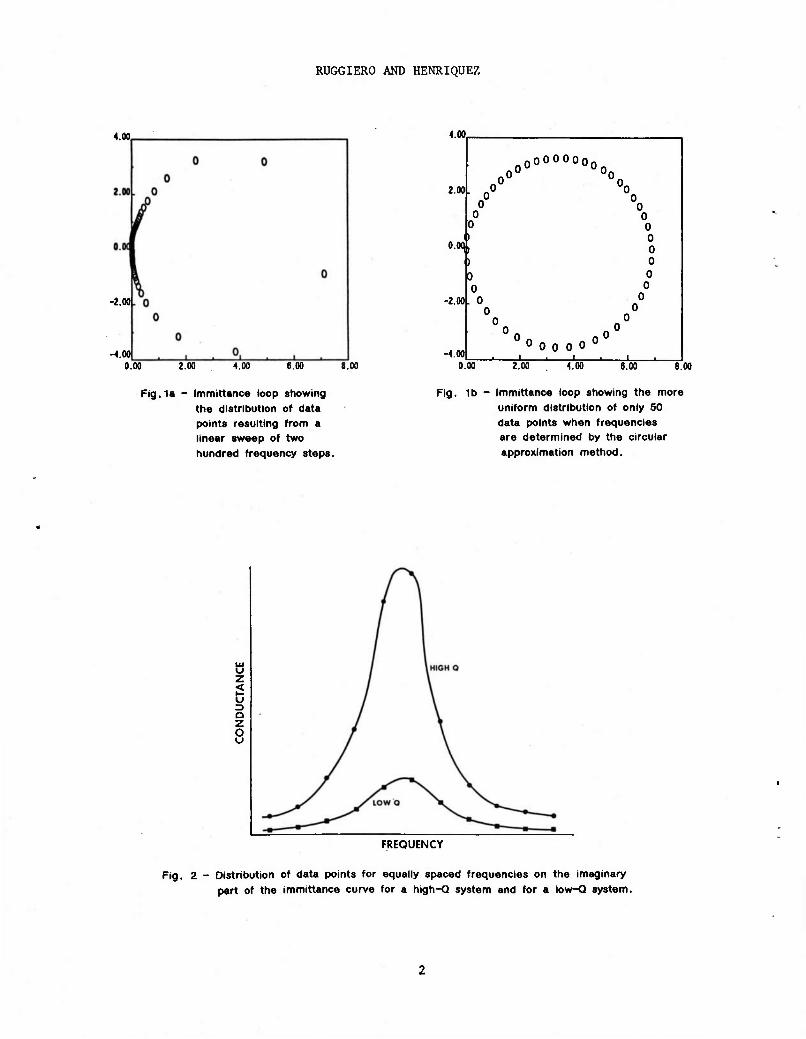
points(i) are stored. These points(i) are illustrated by the "triangles"
in Fig. 3.
RUGGIERO AND HENRIQUEZ
Fig. 3 - An immittance loop with a first-circle approximation. Dots indicate the first three frequencies chosen. Squares mark the 120° points. Triangles represent associated points on immittance loop.
Now a new circle is calculated using the two 120-degree points(c)
(triangles in Fig. 3) and the second intial point(i&c). Note that this new
circle will be a better approximation to the immittance loop than was the
previous one. This procedure iterates until two successive circles are
within the desired tolerance. The result of this convergence is a "best-
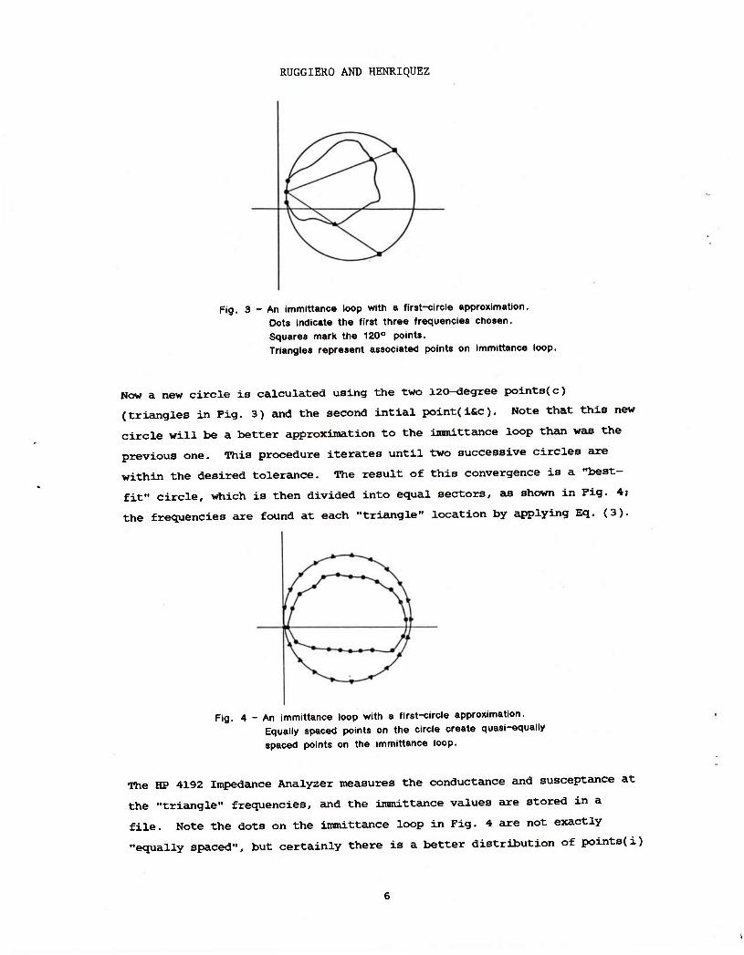
fit" circle, which is then divided into equal sectors, as shown in Fig. 4;
the frequencies are found at each "triangle" location by applying Eq. (3).
Fig. 4 - An immittance loop with a first-circle approximation. Equally spaced points on the circle create quasi-equally
spaced points on the immittance loop.
The HP 4192 Impedance Analyzer measures the conductance and susceptance at
the "triangle" frequencies, and the immittance values are stored in a
file. Note the dots on the immittance loop in Fig. 4 are not exactly
"equally spaced", but certainly there is a better distribution of points(i)

NRL MEMO REPORT 5384
than is obtained from a linear frequency sweep. This is what we previously
referred to as quasi-equally spaced points(i).
CRITICAL FREQUENCIES
Once the loop is characterized with the desired number of quasi-
equally spaced points( i), specific frequency points(f) are needed for later
calculations of various transducer parameters. The frequency points(f) [3]
that are of interest are:
f_: frequency at maximum admittance (minimum impedance)
fn: frequency at maximum impedance (minimum admittance)
f : frequency at maximum conductance
f : frequency at maximum resistance
fr: resonance frequency (susceptance is zero)
fa: antiresonance frequency (susceptance is zero)
fh : frequency at maximum susceptance
a
f^ : frequency at minimum susceptance
a
fn : frequency at maximum reactance i
f, : frequency at minimum reactance
i
When characterizing an admittance loop, the frequency points(f) f^
f„, f_, f,,, f>. , and f, are determined by a maze technique that will be 3 r p nj j.g
described in the program section of this report. When an impedance loop is
characterized, the frequency points(f) fa, f , fR, fg, f^, and f^ are
determined. One may note that the frequency sets differ when calculating

RUGGIERO AND HENRIQUEZ
impedance or admittance loops. The authors believe that the two most
important points(f) are the series and parallel resonance (fg and fp).
These points(f) can easily be found, and they occur for both loaded and
unloaded transducers. Both of these conditions do not apply to the
frequency pairs fm/fn and fa/fr- To determine the frequencies fm/fn one
must do a frequency sweep, which can be rather time consuming. The
points(f) f ,f are easy to find by implementing root-finding techniques;
however these points(f) do not always occur in loaded transducers. For
these reasons, the focus has been on obtaining f_,f_. The reader may note
that f is the frequency at maximum conductance; however, it is not the
frequency of minimum resistance as can be seen in Fig. 5.
z < u <
° RESISTANCE
CONDUCTANCE
Fig. 5 - Impedance loop (5a) and admittance loop (5b), showing their critical frequencies.
Analogously, f is the frequency at maximum resistance; but it is not the
frequency of minimum conductance.
The points(f) of secondary importance are the frequencies of minimum
and maximum susceptance (f n and f^ ). These points(f), sometimes called
half-power points(f), are used to compute the electrical quality factor Q.
We also compute the frequencies of minimum and maximum reactance (f n and
f^ )• These points(f), however, are not the half-power points(f) and cannot
be used for calculating the quality factor Q. The only purpose for
determining these points(f) is that they locate the frequencies at the top
and bottom of the loop. The remaining frequencies are easily determined
for the particular immittance loop calculated, and they serve as helpful

NRL MEMO REPORT 5384
parameters for detecting problems.
PROGRAM
The computer program MICAM, presented herein, is by no means the best
implementation of the circular approximation method. However, the authors
feel confident that this program can be refined in a manner that would be
applicable in any research or manufacturing environment. The MICAM
program, written in FORTRAN 77, is run on a Digital Equipment Corporation
VAX 11/780 computer at the Underwater Sound Reference Detachment of the
Naval Research Laboratory as a research tool as well as a quality-control
problem detector. A version of this program is also written in HP Basic
and can be executed on the HP 9836. The MlCAM program has been tested on
various transducers, both in air and in water, and seems to perform
exceptionally well. It does have limitations, which will be explained in
detail in the RESTRICTIONS section of this report. Since the program is
quite involved, the line-by-line descriptions of MICAM and the program
listings are included in Appendix B. The purpose of examining individual
program lines is to:
o Show how the algorithm has been implemented.
o Give differences in admittance and impedance loops.
o Explain how critical frequencies are determined.
The program MICAM calls three subroutines; SIMEQ, RSORT, and FILE. The
SIMEQ subroutine solves simultaneous equations. The RSORT subroutine sorts
numbers in descending or ascending order. And the FILE subroutine stores
the immittance information in FORTRAN files.
RESTRICTIONS
Limitations exist in all algorithms and should be used as one
criteria for choosing one method over another. The following paragraphs
identify two examples where a linear frequency sweep would be preferable to

RUGGIERO AND HENRIQUEZ
determining frequencies by the circular approximation method.
One problem occurs When running very low-Q or highly damped
transducers where no loops are formed. Since the circular approximation
method is designed to emulate the immittance loop with a circle, the
algorithm fails to converge on very low-Q or highly damped transducers.
The MICAM program accommodates this problem by allowing the user to perform
a frequency sweep. If the transducer is of low Q, a linear frequency sweep
will give quasi-equally spaced points(i), as illustrated in Fig. 2.
A second problem occurs when two or more resonances are in the same
frequency region. They may appear as small or large satellite loops.
Usually the small satellite loops are not a problem and MICAM will converge
to the larger loop. Nevertheless, when immittance is the combination of
loops of relatively the same size, MICAM converges to one of them,
depending on the initial frequency given. This loop may not necessarily be
the one desired. However, the authors feel that MICAM may be optimized for
specific applications by relatively minor programming changes.
CONCLUSION
The circular approximation algorithm, when used with the HP 4192A
Impedance Analyzer, makes a highly efficient system for measuring impedance
and admittance of resonant electromechanical devices. The system has
proven to be applicable to the measurement of active electromechanical
materials as well as composite transducers. The algorithm has been used
with excellent results on a VAX computer as well as on personal computers.
Although specifically developed as a research tool, the automated
immittance measuring system is extremely well suited for quality-control
and production testing of electromechanical transducers and materials.
ACKNOWLEDGMENTS
The authors gratefully acknowledge Dr. Pieter S. Dubbelday for the
initial concept in the circular approximation approach. Also special
10

NRL MEMO REPORT 5384
thanks to Allan Tims and Mark Young for their constant support and
expertise during the development of the circular approximation algorithm
and without whom this work could not have been completed.
This work was supported by NAVSEA Code 63X5 through the Sonar
Transducer Reliability Improvement Program (STRIP), Work Unit II.B.l -
Ceramic Stacks.
REFERENCES
1. Walter Cady, Piezoelectricity, (Dover Publications, Inc., New York,
1964) pp. 336-340
2. Howard Anton, Elementary Linear Algebra, (John Wiley & Sons, Inc., New
York, 1973) pp. 80-82.
3. "IEEE Standand on Piezoelectricity," IEEE Std. 176-1978 (The Institute
of Electrical and Electronic Engineers, Inc., New York, 1978),
11

RUGGIERO AND HENRIQUEZ
(blank page)
12

APPENDIX A
Analysis for Applying Equations to Both Immittance Loops
The characteristic electrical property of a piezoelectric resonator
is the equivalent series chain RLC in Fig. Al. The graphical
representation of the RLC branch is more easily represented by the
admittance which is represented as a circle referred to as the fiducial
circle [l]. The graph can be easily extended to more complicated networks
connected in parallel, such as C .
Fig. A1 - Simple equivalent circuit of a piezoelectric resonator.
The simple form of admittance of the RLC chain is all that is necessary to
approximate the fiducial circle. The argument extends to the impedance
representation in that all the information for the impedance circle is
contained in the admittance circle. If
Y(w) - G(u>) - jB(u),
then
tan(S) = -B(fa>)
[Al]
Since Z(u>) is the complex reciprocal of Y(u), Z(u) can be written as
Z(w) G(u>)
+ j- B(fa>)
G2(u) + B2(u) G2(w) + B2(w) [A2]
13

RUGGIERO AND HENRIQUEZ
or Z(u>) can be written as
Z(u) - R(w) + jX(w). [A3]
Equating the real and imaginary parts of Eqs. (A2) and (A3) results in the
following expressions:
G(co) R(w) - -= K—L-z , [A4]
G (u>) + B (w)
and
B(w) X(w) - — *—*-T . [A5] G (W) + B (w)
For an impedance loop, tan(G) can be written as
tan(e) = §£>' [A6]
or can be equivalently expressed by using Eqs. (A4) and (A5) as
tan(G) = J\ [. G( u)
Note that Eqs. (Al) and (A6) are identical except for being opposite in
sign. Therefore for any u> in the admittance circle there is a
corresponding o> of the same value in the impedance circle with the same but
negative phase value.
14

APPENDIX B
Program Description and Listing
DESCRIPTION
This appendix contains a detailed description of MICAM as well as
program listing. The program description supplements the CIRCULAR
APPROXIMATION ALGORITHM section of this report and is necessary for a full
understanding of this method. Program lines 1-76 are array declarations
while lines 94-145 contain the interactive input section. There are
several items of interest in this section. A question regarding speed is
asked at line 96. Low speed provides an average measurement mode
(approximately one measurement per second) to obtain measurement data of
higher resolution and repeatability then at medium speed (5 measurements
per second) or high speed (10 measurements per second). At line 112, the
number of points(i) refers to the number of quasi-equally spaced points(i)
that are desired on the immittance loop. In lines 118 and 120, the
parallel or series resonance is required depending upon which loop is
calculated. These frequencies are estimated from a priori knowledge. The
more confident one is of these points(f), the smaller the frequency step
size can be taken (line 125).
Lines 138-163 is a section of code that allows the user to perform a
frequency sweep. This is executed only if, for some reason, the circular
approximation method does not apply. The portion of code that includes
lines 176-215 is the location where the conductance and susceptance
(resistance and reactance) for the three initial points(f) are determined.
The ARRAY variable contains the coefficents of Eq. 4. In line 216, the
subroutine SIMEQ solves the three simultaneous equations, which ultimately
results in the center and radius of the circle given in lines 218-220.
The code from lines 221-237 is used to solve Eq. (2) for w^ and 1/L,
which are used to calculate the frequencies at two initial points(i) and
the motional inductance value L (lines 241-250). Line 252 is a decision
statement that determines if the difference between two successive series
15

RUGGIERO AND HENRIQUEZ
(parallel) resonant frequencies is within a desired tolerance. If the
frequency is within tolerance, the program has determined the best fit o^
and L for Eq. (1). If the tolerance is not met, a new and hopefully
better-fit circle will be computed using the frequencies at the two 120-
degree points(c) (lines 261-283). These 120-degree frequency points(f) are
found by solving Eq. (3) and substituting the recently computed values for
ui and L. This entire procedure repeats until the tolerance condition is
met in line 252.
The second major computational portion of the MICAM program is found
in lines 294-321. This portion uses the toi and L that meet the tolerance
specifications and Eq. (3) to calculate the quasi-equally spaced
points(i). The remaining portion of the program determines the critical
frequencies described earlier in this report. The RSORT subroutine sorts
the data from the largest to the smallest value. In line 322, the
conductance (resistance) is sorted so that the first value in the array
will be the f_ (f_). The RSORT subroutine is called again in line 327 s p where frequency is the variable sorted. The remaining critical frequencies
are determined by exercizing a maze technique. This technique is found in
lines 337-384 and is based on previous knowledge on all immittance loops,
shown in Fig. 5. The criteria used are:
f «. f < f < f < f <f. [Bl] msrapn
A critical frequency point(f) is searched only in the region wherein it
could occur; i.e, it satisfies the inequalities of Eq. (Bl). All of the
critical frequencies are chosen from the points(i&f) of the immittance loop
except for f (fg). The points(f) fp(fs) require that more points(f) be
calculated in order to have relatively accurate data. For example, when an
admittance loop has been run, f is determined by switching the HP analyzer
to the impedance mode, spotting the point(f) f^ , and sweeping the
frequency until the frequency at maximum impedance is found. On the other
hand, when an impedance loop has been run, fs is determined by switching
the analyzer to the admittance mode, spotting the point(f) fh , and then
sweeping the frequency in reverse until the frequency of maximum admittance
is found. This technique is illustrated in lines 408-431.
16

NRL MEMO REPORT 5384
The remaining portion of the program can be considered a formatted
output section that prints a table of all critical frequencies described
and files the data points(i) for plotting. The plots that can be created
include a graph of magnitude of immittance verses frequency and a graph of
the imaginary part of immittance verses the real part of immittance. Also
the critical frequencies are stored so they may be overlayed on the
immittance plot as shown in Pigs. Bl and B2, which are examples of
admittance loops obtained on a USRD Type F42A transducer in air and in the
USRD Lake Facility by MICAM.
20 30
G SIEMENS (x 10-3) G SIEMENS (* 10"31
Fig. B1 - Admittance loop obtained on an F42A transducer in air.
Fig. B2 - Admittance loop obtained on an F42A transducer in the USRD Lake Facility.
There are several differences in MICAM for impedance or admittance
loops. The first difference, of course, is that the HP analyzer is in the
proper mode for the desired measurements (lines 171 and 172). Secondly,
there is a difference in the motional resistance (R) found in Eqs.(l)
through (3) for the two loops. In the admittance mode, R is approximated
by the reciprocal of the diameter, and in the impedance mode, R is
approximated by simply using the diameter of the circle. Two interactive
runs of the program MICAM are included in Appendix B, which illustrate how
17

RUGGIERO AND HENRIQUEZ
the user can obtain results in either imnittance mode.
18

LISTING
NRL MEMO REPORT 5384
0001 0002 0003 C 0004 0006 C 0006 C 0007 0008 C THIS 0009 C 0010
0011
0012
0013
0014
0015
0016
0017
0018
0019
0020
0021
0022
0023
0024
0025
0026
0027
0028
0029
0030
0031
0032
0033
0034
0035
0036
0037
0038
0039
0040
0041
0042
0043
0044
0045
0046
0047
0048
0049
0050
0051
C c
MICAM PROGRAM
WRITTEN BY TINA RUGGIERO FEBRUARY, 1983
PROGRAM DETERMINES A FREQUENCY SWEEPING FUNCTION BY APPROXIMATING AN ADMITTANCE LOOP WITH A PERFECT CIRCLE. ALSO FN.FM, FA.FR, AND ADMITTANCE LOOPS ARE STORED AND ARE AVAILABLE FOR PLOTTING.
DOUBLE PRECISION DEF (3), CONS (3), ARRAY(3,3). COEFF(3,3), COLUMN (3), ANS (3) REAL RESdOOO), XESdOOO), FREQ(1000),X(6), Y(6), F(6), FR(3), FREdOOO) REAL K33, CE, CP, COB, CAP, XCOF(5), COF(5), ROOTR (5), ROOTI (5), ADM(1000) REAL CRX(8),CRY(9),MAG(1000) COMMON FR, AMR, RR, XR, FA, AMA, RA, XA, FM, AMM, RM, XM, FN, AMN, RN, XN, XH, XL COMMON RH,RL,FH,FL COMMON /LENGTH/LEN
BYTE ANSWER (80)
BYTE A(13) DATA A /'OVL'.O.O.O.O.O.O.O.O.O.'EVNV
BYTE B(12) DATA B /T, *F\ 0,0,0,0.0,0', 0,0, 'E', 'N7
BYTE C(13) DATA C /'P'.T.O.O.O.O.O.O.O.O.O.'EVNy
BYTE D(12) DATA D /'S', 'F, 0,0,0,0,0,0,0.O.'E'.'NV
BYTE E(13) DATA E /'P, "R1,0,0,0,0,0,0,0,0,0. 'E', *N7 BYTE IDSP(4) DATA IDSP /'F'.'Y.'K'.'V/
BYTE IADV(2) DATA IADV /•W\,27
BYTE IREV(2) DATA IREV IVT.'VI
BYTE IADK2) DATA IAD1 /'DV17
BYTE IAD0(2)
! VOLTS
! START
! STOP
! STEP
I SPOT
DIS
ISTEP UP
ISTEP DOWN
IDATA READY ON
(DISPLAY CAP
19
RUGGIERO AND HENRIQUEZ
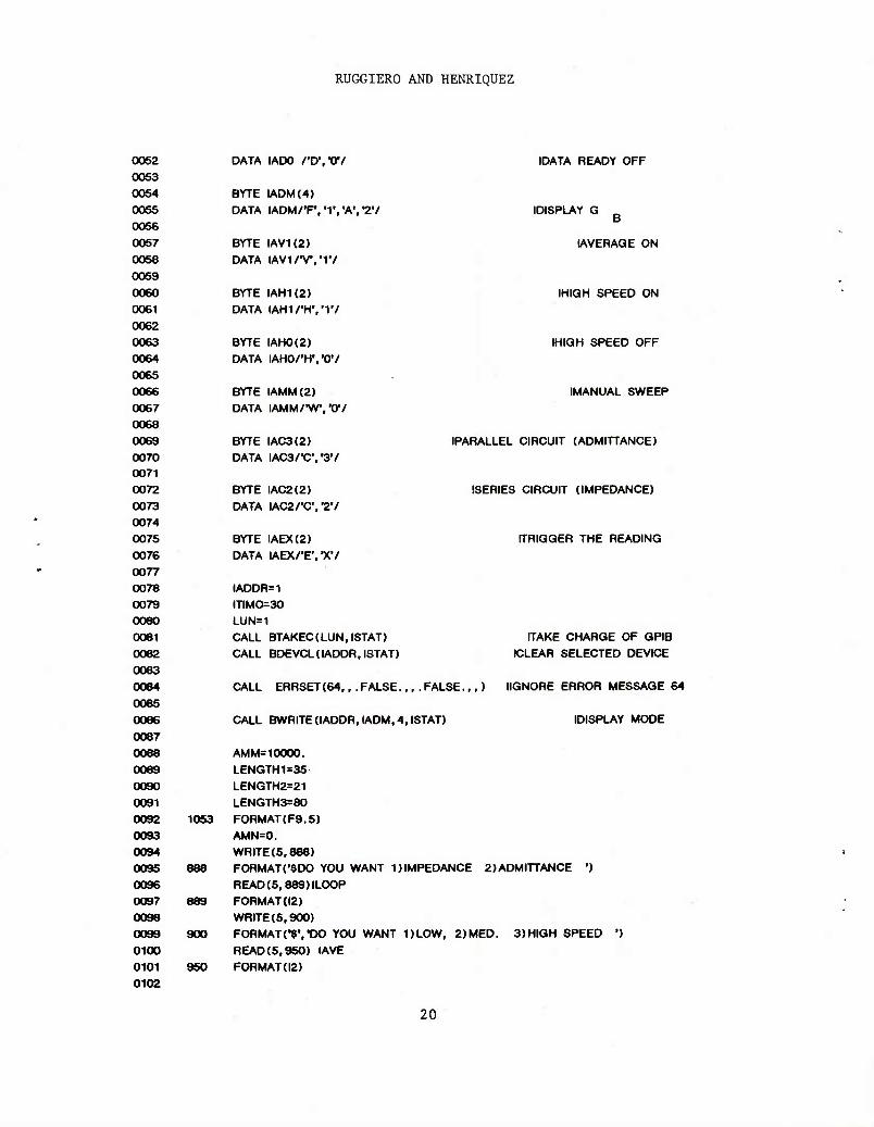
0052 0053 0054 0055 0056 0057 0058 0059 0060 0061 0062 0063 0064 0065 0066 0067 0068 0069 0070 0071 0072 0073 0074 0075 0076 0077 0078 0079 0080 0061 0082 0083 0084 0085 0086 0087 0088 0089 0090 0091 0092 0093 0094 0095 0096 0097 0098 0099 0100 0101 0102
DATA IADO rD'.V/
BYTE IADM(4) DATA lADM/'F.'IVA'.^V
BYTE IAVK2) DATA lAVVWIV
BYTE IAHK2) DATA lAM/'HW/
BYTE IAH0(2) DATA lAHO/'H'/OV
BYTE IAMM(2) DATA IAMM/"WV07
BYTE IAC3(2) DATA IAC3/"C\,3y
BYTE IAC2(2) DATA IAC2/,C\,27
BYTE IAEX(2) DATA IAEX/"E\ "X7
IADDR=1 ITIM0=30 LUN=1 CALL BTAKEC(LUN.ISTAT) CALL BDEVCL (IADDR, ISTAT)
IDATA READY OFF
(DISPLAY G
IAVERAGE ON
(HIGH SPEED ON
IHIGH SPEED OFF
IMANUAL SWEEP
(PARALLEL CIRCUIT (ADMITTANCE)
ISERIES CIRCUIT (IMPEDANCE)
ITRIGGER THE READING
ITAKE CHARGE OF GPIB «LEAR SELECTED DEVICE
CALL ERRSET(64,, .FALSE... .FALSE.,,) IIGNORE ERROR MESSAGE 64
CALL BWRITE(IADDR,IADM,4,ISTAT) IDISPLAY MODE
AMM= 10000. LENGTH1=35 LENGTH2=21 LENGTH3=80
1053 F0RMAT(F9.5) AMN=0. WRITE (5.888)
888 FORMAT C8D0 YOU WANT 1) IMPEDANCE 2) ADMITTANCE ') READ(5,889)ILOOP
889 FORMAT (12) WRITE (5,900)
900 FORMAT(•$•,'DO YOU WANT DLOW, 2)MED. 3)HIGH SPEED ') READ (5,950) IAVE
950 FORMAT (12)
20

NRL MEMO REPORT 5384
0103 0104 0106 0106 0107 0108 0109 0110 0111 0112 0113 0114 0115 0116 0117 0118 0119 0120 0121 0122 0123 0124 0125 0126 0127 0128 0129 0130 0131 0132 0133 0134 0135 0136 0137 0138 0139 0140 0141 0142 0143 0144 0145 0146 0147 0148 0149 0150 0151 0152 0153
10 1000
1060 1070
1010
1011
1030
1035
1040
1066
WRITE(5,1000) FORMAT (/•$', "ENTER THE VOLTAGE LEVEL (IN VOLTS): READ(5,1060,ERR=10) VOLTS ENCODE (9,1070, A (3) ) VOLTS CALL BWRITE (IADDR, A, 13, ISTAT) FORMAT(FIO.O) FORMAT(F9.4) NTIMES=1
WRITE(5,1111) 1111 FORMAT( "5 ENTER # OF POINTS ')
READ(5,1020)NPTS 1020 FORMATU4) 20 NTIMES=NTIMES*1
1044
IF (ILOOP .EQ. 1)WRITE(5,1010) FORMAT (/V, "ENTER FREQUENCY (PARALLEL RESONANCE) (IN KHZ): ")
IF (ILOOP .EQ. 2)WRITE(5,1011) FORMAT (/•$', 'ENTER FREQUENCY (SERIES RESONANCE) (IN KHZ): ')
READ(5,1060,ERR=20) START_FREQ ITIME=1
WRITE (5,1030) FORMAT (CENTER STEP FREQ (IN KHZ): ')
READ(5,1060)STEP_FREQ IF(NTIMES .LT. 5)THEN
GOTO 3000 ELSE
TYPE *,'DO YOU WANT TO SWEEP FREQ?' READ (5,1035)ISWEEP
FORMAT (A2) IFdSWEEP .EQ. "N'jTHEN
NTIMES=-10 GO TO 3000
END IF 1=1 ENCODE (8,1066, D(3) )STEP_FREQ CALL BWRITE (IADDR, D, 12, ISTAT) WRITE(5,1040)
FORMAT(/,'SENTER THE STOPPING FREQ (KHZ) READ (5,1060) STOP ENCODE (9,1070, C (3)) STOP
FORMAT (F8.4) CALL BWRITEdADDR.C, 13, ISTAT) ENCODEO, 1070,E(3))START_FREQ CALL BWRITE (IADDR, E, 13, ISTAT)
CALL BWRITE (IADDR, IAMM, 2, ISTAT) CALL BWRITE (IADDR, IAEX, 2, ISTAT)
DO J=1,80 ANSWER (J)=0
(SPOT FREQUENCY
IMANUAL MODE (TRIGGER
21

RUGGIERO AND HENRIQUEZ
0154
0155 0156 0157 0158 0159 0160 0161 0162 0163 0164 0165 0166 0167 0168 0169 0170 0171 0172 0173 0174 0175 0176 0177 0178 0179 0180 0181 0182 0183 0184 0185 0186 0187 0188 0189 0190 0191 0192 0193 0194 0195 0196 0197 0198 0199 0200 0201 0202 0203 0204
END DO
CALL BREADdADDR,ANSWER, LENGTH3. ISTAT) DECODE (12.1050, ANSWER (5)) RES (I) DECODE (12.1050, ANSWER (21) )XES (I) DECODEO, 1053,ANSWER(35))FREQ(I) IF (FREQ(I) .QE. STOPJGOTO 88 CALL BWRITE(IADDR,IADV,2.ISTAT) 1=1+1 GO TO 1044 END IF
3000 STEPI=STEP_FREQ
IF (IAVE.EQ.1) CALL BWRITEdADDR. IAV1,2, ISTAT) IFOAVE .EQ. 3)CALL BWRITEdADDR,IAH 1,2,ISTAT) IFdAVE .EQ. 2)CALL BWRITEdADDR,IAHO,2,ISTAT)
48
49
1050
(ADVANCE FREQ.
IAVERAGE SPEED IHIGH SPEED
INORMAL SPEED
CALL BWRITEdADDR, IAMM, 2, ISTAT) IMANUAL MODE IFdLOOP .EQ. 2)CALL BWRITEdADDR, IAC3.2, ISTAT) (CIRCUIT TYPE 3 IFdLOOP .EQ. DCALL BWRITEdADDR,IAC2,2,ISTAT) iCIRCUIT TYPE 2
IF (IT .GT. 1) CONTINUE
DO 1=1,3 IFdTIME .GE. 2) THEN
IFd .EQ. 2)GOTO 85 FREQUENCY=ABS(FR (I)/(1000. »2*3.14159)) ENCODE(9,1070,E(3)) FREQUENCY CALL BWRITEdADDR, E, 13. ISTAT)
FREQ(I)=FREQUENCY ELSE
ENCODE (9,1070, E(3)) START_FREQ CALL BWRITEdADDR, E, 13, ISTAT)
FREQ(I)=START_FREQ END IF
! SPOT STARTING POINT
! SPOT STARTING POINT
CALL BWRITEdADDR, IAEX,2, ISTAT) DO J=1,80
ANSWER (J)=0 END DO K=0
CALL BREADdADDR,ANSWER,LENGTH1,ISTAT) DECODE (12,1050, ANSWER (5)) RES (I) DEC0DEO2,1050,ANSWER(21))XES(I)
F0RMAT(E12.2) IFdTIME.EQ. LAND.I.EQ.DTHEN
FREQA=FREQ(1) XESA=XES(1) RESA=RES(1)
ELSE END IF FREQ(I)=FREQ(I)*1000
(TRIGGER THE READING
22

NRL MEMO REPORT 5384
0205 0206 0207 0208 0209 0210 0211 0212 0213 0214 0215 0216 0217 0218 0219 0220 0221 0222 0223 0224 0225 0226 0227 0228 0229 0230 0231 0232 0233 0234 0235 0236 0237 0238 0239 0240 0241 0242 0243 0244 0245 0246 0247 0248 0249 0250 0251 0252 0253 0254 0255
85 ARRAY(I,1)=RES(I) ARRAY(I,2)=XES(I) ARRAY(I,3) = 1. CONS(l)=-(RES(l)*RES(l)+XES(l)*XES(D) IF (ITIME. EQ. 1) START_FREQ=START_FREQ+STEP_FREQ
END DO
C SIMEQ IS A SUBROUTINE THAT SOLVES SIMELTANEOUS EQUATIONS C USED TO FIND COEFICIENTS OF A GENERALIZED CIRCLE
N=3 INUMBER OF PARAMETERS CALL SIMEQ(N,ARRAY,CONS,DEF) IF(N .EQ. 0)GO TO 20 CENTERX=-DEF(1)/2. K VALUE OF CENTER CENTERY=-DEF(2)/2. !Y VALUE OF CENTER RADIUS=.5*SQRT(DEF(1)*DEF(1)+DEF(2)*DEF(2)-4*DEF(3)) IFOLOOP .EQ. 2)RESIS=1./(2*RADIUS) (RESISTANCE (ADMITTANCE) IFOLOOP .EQ. 1)RESIS=2*RADIUS RESISTANCE (IMPEDANCE)
C SLOPE IS THE TAN(THETA) IN EQUATION 1
SL0PE1=((XES(1)-CENTERY)/(RES(1)-CENTERX+RADIUS)) SL0PE2= ((XES(2)-CENTERY) / (RES(2)-CENTERX+RADIUS)) SL0PE3= ((XES(3)-CENTERY) / (RES(3)-CENTERX+RADIUS))
COEFF (1,1)=SLOPE1 *RESIS*6.283185*FREQ (1) COEFF(2,1)=SL0PE2*RESIS*6.283185*FREQ(2) COEFF(1,2) = 1. COEFF(2,2) = 1. COLUMN(1)=(2*3.14159*FREQ(1))**2 COLUMN (2)= (2*3.14159*FREQ(2))**2
N=2 CALL SIMEQ(N,COEFF,COLUMN,ANS) IF(N .EQ. 0)GOTO 20
C ANS( I) is the Inductor C ANS(2) is the Resonant Freq.
IF (ANS (2) .LT. OJGOTO 20
ANS(1)=1/ANS(1) ANS(2)=SQRT(ANS(2)) IF (ANS (2) .EQ. 0)GOTO 20 RES0NANCE=ANS(2) /6283.185 WRITE(5, 77)ANS(2)/6283.185
77 FORMATC FREQ= \F10.3)
IF (ABS (ANS (2) -OMEGA) /6283. LE. (. 0005*FREQA) ANS (2)= (0MEGA+ANS(2)) /2.
ANS(1) = (RINDUCT0R+ANS(1))/2. GOTO 50
OR. ITIME .GE. 25)THEN
23

RUGGIERO AND HENRIQUEZ
0256 0257 0258 0259 0260 0261 C 0262 0263 0264 0265 0266 0267 0268 0269 0270 0271 0272 0273 0274 0275 0276 0277 0278 0279 0280 0281 0282 0283 0284 50 0285 0286 0287 0288 0289 0290 0291 0292 0293 0294 0295 0296 0297 0298 0299 0300 0301 0302 0303 0304 0305 9 0306
ELSE OMEOA=ANS (2) RINDUCT0R=ANS(1)
END IF
ANGLES OF OTHER 2 POINTS
TRANSX1=RES(2)-CENTERX TRANSY1=XES (2)-CENTERY TRANSA1=ATAN2(TRANSY1, TRANSX1) X2=C0S (TRANSA1+2.094395) «RADIUS+CENTERX X3=C0S (TRANSA1-2.094395) *RADIUS+CENTERX Y2=SIN (TRANSA1+2.094395) *RADIUS+CENTERY Y3=SIN (TRANSA1-2.094395) *RADIUS+CENTERY
SL0PE1= (Y2-CENTERY) / (X2-CENTERX+RADIUS) SL0PE3= (Y3-CENTERY) / (X3-CENTERX+RADIUS) B1=-SL0PE1*RESIS B2=-SLOPE2*RESIS B3=-SLOPE3*RESIS
FR(1)=-B1-SQRT(B1*B1+4.»ANS(1)**2*(ANS(2)*ANS(2))) FR(1)=FR(1)/(2*ANS(D) FR(2)=FREQ(2)*2*3.14159 FR (3) =-B3-SQRT (B3*B3+4. *ANS (1) **2* (ANS (2) "ANS (2))) FR(3)=FR(3)/(2*ANS(D) ITIME=ITIME+1 IFdTIME .GE. 2)GOTO 49
R=SQRT(RESA*RESA+XESA*XESA) THETA=ATAN2(XESA, RESA) A0=SQRT((CENTERX-RESA)**2 + (CENTERY-XESA) **2) C0NVERT=1.74532E-02 TIM=359./NPTS Pl=3.14159 TRANSX=RESA-CENTERX TRANSY=XESA-CENTERY THETA=ATAN2(TRANSY, TRANSX) 1=1 DO IT=1,NPTS DELTA2=IT*TIM*CONVERT+THETA X3= (COS (DELTA2) »RADIUS)+CENTERX Y3= (SIN (DELTA2) »RADIUS) +CENTERY
SL0PE3= (Y3-CENTERY) / (X3-CENTERX+RADIUS)
B3=-SL0PE3*RESIS
FRE(l)=-B3+SQRT(B3*B3+4. *ANS(1)**2*(ANS(2)*ANS(2))) FRE(I)=FRE(I)/(2.*ANS(D) FREQUENCY=ABS(FRE(I)/(1000. *2*3.14159)) T0LERANCE1=2.5*RES0NANCE
IF ( FREQUENCY .GT. TOLERANCEDGOTO 70
24
NRL MEMO REPORT 5384
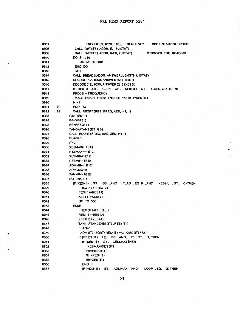
0307 ENCODE (9,1070, E (3)) FREQUENCY I SPOT STARTING POINT 0308 CALL BWRITE(IADDR,E,13,ISTAT) 0309 CALL BWRITE(IADDR,IAEX,2,ISTAT) (TRIGGER THE READING 0310 DO J=1,80 0311 ANSWER (J)=0 0312 END DO 0313 K=0 0314 CALL BREADOADDR, ANSWER, LENGTH 1.ISTAT) 0315 DECODE (12,1050, ANSWER (5)) RES (I) 0316 DEC0DE02,1050. ANSWER(21))XES(I) 0317 IF(RES(I) .GT. 1.3E6 .OR. XES(IT) .GT. 1.3E6JG0 TO 70 0318 FREQ(I)=FREQUENCY 0319 MAG(I)=SQRT(RES(I)*RES(I)+XES(I)*XES(I)) 0320 1=1+1 0321 70 END DO 0322 88 CALL RSORT(RES, FREQ,XES,I-1,1) 0323 GS=RES(1) 0324 BS=XES(1) 0325 FS=FREQ(1) 0326 TAN0=ATAN2(BS,GS) 0327 CALL RSORT(FREQ,RES.XES, 1-1,1) 0328 FLAG=0 0329 IT=2 0330 XESMAX=-1E12 0331 RESMAX=-1E12 0332 XESMIN=1E12 0333 RESMIN=1E12 0334 ADMMIN=1E12 0335 ADMMAX=0 0336 TANMIN=1E12 0337 DO J=2,l-1 0338 IF(XES(J) .GT. BS .AND. FLAG .EQ.O .AND. XES(J) .GT. 0)THEN 0339 FREQ(1) = FREQ(J)
0340 RES(1) = RES(J)
0341 XES(1)=XES(J)
0342 GO TO 500
0343 ELSE
0344 FREQ(IT)=FREQ(J)
0345 RES(IT)=RES(J)
0346 XES(IT)=XES(J)
0347 TAN1=ATAN2(XES(IT),RES(IT))
0348 FLAG=1
0349 ADM(IT)=SQRT(RES(IT)**2 +XES(IT)**2)
0350 IF(FREQdT) ,LE. FS .AND. IT .GT. DTHEN 0351 IF(XES(IT) .GE. XESMAX)THEN 0352 XESMAX=XES(IT) 0353 FH=FREQ(IT) 0354 GH=RES(IT) 0355 BH=XES(IT) 0356 END IF 0357 IF (ADM (IT) .GT. ADMMAX .AND. ILOOP .EQ. 2)THEN
25

RUGGIERO AND HENRIQUEZ
0358 ADMMAX=ADM(IT) 0359 FM=FREQ(IT) 0360 QM=RES(IT) 0361 BM=XES(IT) 0362 END IF 0363 IF(XES(IT-1) .LT. 0 .AND. XES(IT) .QT. 0)THEN 0364 FRES=FREQ(IT) 0365 GR=RES(IT) 0366 BR=XES(IT) 0367 END IF 0366 END IF 0369 IF(FREQ{IT) .GE. FS .AND. IT .GT. DTHEN 0370 IF(XES(IT) .LE. XESMIN)THEN 0371 XESMIN=XES(IT) 0372 FL=FREQ(IT) 0373 GL=RES(IT) 0374 BL=XES(IT) 0375 END IF 0376 IF(XES(IT-1) .LT. 0 .AND. XES(IT) .GT. 0)THEN 0377 FRES=FREQ(IT) 0378 GR=RES(IT) 0379 BR=XES(IT) 0380 END IF 0381 IF(ADMOT) .GT. ADMMAX .AND. ILOOP .EQ. DTHEN 0382 ADMMAX=ADM(IT) 0383 FN=FREQ(IT) 0384 GN=RES(IT) 0385 BN=XES(IT) 0386 ENDIF 0387 END IF 0388 IT=IT+1 0389 END IF 0390 500 END DO 0391 IF(ILOOP. EQ. DTHEN 0392 WRITE (5,1109) 0393 1109 FORMAT( ///, 9X, TYPE', 11X, 'FREQUENCY (KHZ) *, 2X, 'RESISTANCE', 2X, 0394 1'REACTANCE') 0395 ELSE 0396 WRITE (5,1110) 0397 1110 FORMAT (///, 9X, TYPE',11X, 'FREQUENCY (KHZ)', 2X, 'CONDUCTANCE', 2X, 0398 1'SUSCEPTANCE") 0399 END IF 0400 0401 0402
1112 WRITE (5,1112)
rUHMAItw, , 11A, , £A, " ,
I«£A, , /;
0403 IF(FRES .EQ. 0)THEN 0404 IF(BL .LT. 0)THEN 0405 FRES=FS 0406 GR=GS 0407 BR=BS 0408 WRITE(5,1130)FRES,GR,BR
26

NRL MEMO REPORT 5384
0409 ELSE 0410 WRITE (5,1120) 0411 1120 FORMAT (1X,'RESONANCE'. 17X," DOES NOT EXIST*) 0412 END IF 0413 ELSE 0414 IFdLOOP .EQ. 2)WRITE(5,1130)FRES,GR,BR 0415 1130 FORMATOX,'RESONANCE'. 16X.F8.3, 7X, E8.3.5X.E9.3) 0416 IFdLOOP .EQ. 1)WRITE(5,1131)FRES,GR,BR 0417 1131 FORMAT dX.'ANTIRESONANCE', 12X.F8.3,7X, E8.3.5X.E9.3) 0418 END IF 0419 CALL BWRITE(IADDR,IAMM,2,ISTAT) IMANUAL MODE 0420 FLAG 1=0 0421 ENCODE(8,1066, D(3)). 1 ISTEP SIZE 0422 CALL BWRITEdADDR, D, 12, ISTAT) 0423 IFdLOOP .EQ. DCALL BWRITEdADDR, IAC3.2, ISTAT) 0424 IFdLOOP .EQ. 2)CALL BWRITEdADDR, IAC2,2,ISTAT) 0425 IFdLOOP .EQ. 2)ENC0DE(9,1070,E(3))FL 0426 IFdLOOP .EQ. 1) ENCODE(9,1070, E (3))FH 0427 CALL BWRITEdADDR,E, 13,ISTAT) ISPOT 0428 GP=0 0429 1270 CALL BWRITEdADDR,IAEX,2,ISTAT) 0430 DO J=1,80 0431 ANSWER (J)=0 0432 END DO 0433 CALL BREADdADDR, ANSWER, LENGTH3, ISTAT) 0434 DEC0DEO2,1050, ANSWER (5)) A1 0435 DECODE (12,1050, ANSWER (21)) B1 0436 DECODE (9,1053, ANSWER (35)) F1 0437 IF(A1 .GE. GP )THEN 0438 FP=F1 0439 GP=A1 0440 BP=B1 0441 IFdLOOP .EQ. 0442 IFdLOOP .EQ. 0443 GO TO 1270 0444 ELSE 0445 FLAG1=FLAG1+1 0446 IF(FLAG1 .EQ. 1) THEN 0447 IFdLOOP. EQ.2)CALL BWRITE(IADDR,IADV,2.ISTAT) 0448 IFdLOOP. EQ. DCALL BWRITEdADDR, IREV, 2, ISTAT) 0449 FP=F1 0450 GP=A1 0451 BP=B1 0452 GOTO 1270 0453 END IF 0454 END IF 0455 NUM=8 0456 CRX(1)=GS 0457 CRY(1)=BS 0458 CRX(2)=GP 0459 CRY(2)=BP
2)CALL BWRITEdADDR, IADV, 2, ISTAT) DCALL BWRITEdADDR, IREV,2, ISTAT)
[ADVANCE IREVERSE
27

RUGGIERO AND HENRIQUEZ
0460 CRX(3)=QM 0461 CRY(3)=BM 0462 CRX(4)=GN 0463 CRY(4)=BN 0464 CRX(5)=GH 0465 CRY(5)=BH 0466 CRX(6)=GL 0467 CRY(6)=BL 0468 IF(FRES .EQ. 0)THEN 0469 NUM=NUM-1 0470 ELSE 0471 CRX(7)=GR 0472 CRY(7)=BR 0473 END IF 0474 IF (FA .EQ. 0)THEN 0475 NUM=NUM-1 0476 ELSE 0477 CRX(8)=GA 0478 CRY(8)=BA 0479 END IF 0480 IFdLOOP .EQ. 2)WRITE(5,1160)FS,GS, BS 0481 IFdLOOP .EQ. 1)WRITE(5,1160)FP.GP.BP 0482 1160 FORMAT(1X,'SERIES RESONANCE", 9X.F8.3,7X, E8.3.5X.E9.3) 0483 IFdLOOP .EQ. 2)WRITE(5,1170)FP.GP.BP 0484 IFdLOOP .EQ. 1)WRITE(5.1170)FS,GS,BS 0485 1170 FORMATdX,'PARALLEL RESONANCE',7X,F8.3,7X,E8.3.5X,E9.3) 0486 IFdLOOP .EQ. 2)WRITE(5,1180)FM,GM,BM 0487 1180 FORMATdX.'MAXIMUM ADMITTANCE',7X.F8.3, 7X.E8.3,5X.E9.3) 0488 IFdLOOP .EQ. 1) WRITEC5,1280)FN,GN, BN 0489 1280 FORMATdX,'MAXIMUM IMPEDANCE', 8X, F8.3, 7X, E8.3.5X, E9.3) 0490 WRITE(5,1190)FH,GH,BH 0491 1190 FORMATdX,'HIGH POINT, 15X.F8.3,7X,E8.3,5X,E9.3) 0492 WRITE(5,1200)FL,GL,BL 0493 1200 FORMATdX,'LOW POINT*. 16X,F8.3,7X,E8.3,5X,E9.3) 0494 WRITE (5,1300)7 0495 1300 FORMAT(//,' '.AD 0496 IFdLOOP .EQ. 2)TYPE «/ADMITTANCE LOOP* 0497 IFdLOOP .EQ. DTYPE *,'IMPEDANCE LOOP 0498 CALL FILE (IT-1, RES. XES) 0499 TYPE V " 0500 TYPE *, 'CRITICAL FREQUENCIES' 0501 CALL FILE (NUM. CRX, CRY) 0502 TYPE V ' 0503 TYPE VFREQ VS. MAG.' 0504 CALL FILEdT-I.FREQ.MAG) 0505 CALL BDEVCLdADDR.ISTAT) (CLEAR SELECTED 0506 END
28
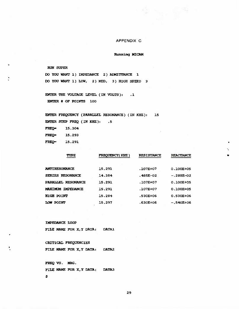
APPENDIX C
Running MICAM
RUN SUPER
DO YOU WANT 1) IMPEDANCE 2) ADMITTANCE 1
DO YOU WANT 1) LOW, 2) MED, 3) HIGH SPEED 3
ENTER THE VOLTAGE LEVEL (IN VOLTS): .1
ENTER # OP POINTS 100
ENTER FREQUENCY (PARALLEL RESONANCE) (IN KHZ):
ENTER STEP FREQ (IN KHZ): .5
PREß- 15.304
PREß- 15.293
FREQ- 15.291
15
TYPE FREQUENCY( KHZ) RESISTANCE REACTANCE
ANTIRESONANCE 15.291 .107E+07 0.100E+05
SERIES RESONANCE 14.384 .485E-02 -.288E-02
PARALLEL RESONANCE 15.291 .107E+07 0.100E+05
MAXIMUM IMPEDANCE 15.291 .107E+07 0.100E+05
HIGH POINT 15.284 . 530E+06 0.530E+06
LOW POINT 15.297 .630E+06 -.540E+06
IMPEDANCE LOOP
FILE NAME FOR X,Y DATA: DATA1
CRITICAL FREQUENCIES
FILE NAME FOR X,Y DATA: DATA2
FREQ VS. MAG.
FILE NAME FOR X,Y DATA: DATA3
5
29

RUGGIERO AND HENRIQUEZ
RUN SUPER
DO YOU WANT 1) IMPEDANCE 2) ADMITTANCE 2
DO YOU WANT 1) LOW, 2) MED, 3) HIGH SPEED 3
ENTER THE VOLTAGE LEVEL (IN VOLTS): .1
ENTER # OP POINTS 100
ENTER FREQUENCY(SERIES RESONANCE) (IN KZH):
ENTER STEP PREQ (IN KHZ): .5
FREQ= 14.390
PREQ- 14.372
FREQ= 14.372
14
TYPE FREQUENCY(KHZ) CONDUCTANCE SUSCEPTANCE
RESONANCE 14.375 .678E-02 0.300E-04
SERIES RESONANCE 14.373 .679E-02 0.540E-03
PARALLEL RESONANCE 15.291 .107E+07 0.OOOE+OO
MAXIMUM ADMITTANCE 14.373 .677E-02 0.790E-03
HIGH POINT 14.357 .311E-02 0.379E-02
LOW POINT 14.391 .327E-02 -.316E-02
ADMITTANCE LOOP
FILE NAME FOR X,Y DATA: DATA1
CRITICAL FREQUENCIES
FILE NAME FOR X,Y DATA: DATA2
FREQ VS. MAG.
FILE NAME FOR X,Y DATA: DATA3
$
30


![Microcopy: a taxonomy and synthesis of best practices · Microcopy can alleviate a user's potential concerns [1]. Like instructional microcopy, concern alleviators can be used to](https://img.pdfslide.us/doc/110x75/60b2dae745235b5cb9229295/microcopy-a-taxonomy-and-synthesis-of-best-microcopy-can-alleviate-a-users-potential.jpg)