Embed Size (px)
Citation preview

> c h e m i c a l m i c r o p r o c e s s t e c h n o l o g y m a d e b y i m m
5/09T H E C ATA L O G U E
For further questions please do not hesitate to contact us:
Institut für Mikrotechnik Mainz GmbHCarl-Zeiss-Straße 18-2055129 Mainz
Phone: +49 61 31 / 990 - 0Fax: +49 61 31 / 990 - 205
Sta
tus
05/2
009
Th
e c
ata
log
ue
5/0
9
> c
he
mic
al
mic
ro p
roc
es
s t
ec
hn
olo
gy
ma
de
by
im
m

1
Continuing roots and shaping up for
future quests
Central new feature in the ‘basket of goods’ are pilot- and production-scale microstructured reactors and whole respective reactor systems, stemming from validated and (partially) docu-mented developments within indus-trial driven national and European projects; all oriented towards target production and prove (cost) competi-tiveness. Two such highlights ex-emplary for the whole approach & portfolio are a setup comprising a modular micro-reactor followed by a milli-scaled tube bundle for the pro-duction of ionic liquids at a capacity of 100 kg/d and pilot- and production-scale microstructured Falling Film Microreactors. Both have stood the test in demonstration processing at in-dustrial sites. Both serve to show how micro process engineering can speed up the scale up process.
PREFACE
It is always a pleasure to introduce the next generation of development and to sum up what this is about and what is beyond. The new catalogue com-prises a diversifi ed, but also refocused offer of microstructured reactors and their processing plants.
All ears on benefi t
New technologies create new oppor-tunities and may strengthen the competitiveness, but also demand for careful implementation and use at the right spot. Technological overshoot and veering away from demand is to be avoided. IMM’s micro process technology ever since is truly devoted to real-life applications in the fi eld of chemical processing, fuel processing, consumer goods, etc. guided by a wealth of experience in customers’ needs. This ‘echo box’ mirrors the long lasting and steady information exchange about user’s practise from innumerable direct discussions, but also arising from the excerpts and essences attained from the global platforms such as symposia, plat-forms and expert groups’ meetings.
More than meets the eye
Single developments into an entirely new direction should not be iso-lated, but should be governed and marshalled by a persistent general idea how to approach the endeavour. Leitmotifs of IMM’s process techno-logy are:
• Scale-out – from laboratory to production scale• System integration – from single devices to integrated reactors and plants• Holistic view – from conventional to novel process windows• Accommodate as appropriate – from micro to milli scale
THE NEW CATALOGUE
– DIVERSIFIED IN PARTS & INTEGRATED AS APPROACH

2
PREFACE
Branch and whole tree
Process intensifi cation is a dramatic and far-reaching change in chemical production technology. The same holds for microreaction technology as the major PI approach. Needed is interdisciplinary bridging in the format of a comprehensive and holistic micro process development. This may be subsumed in fi ve PI pillars “Catalysts – Fabrication – Reactors – Plants – Pro-cesses”. It is the vision and skills on catalysts, fabrication and processes which adds to the hardware develop-ment based on reactors and plants.
IMM has developed brazing as a high-pressure interconnection technique suited for large formats and numbers. This fabrication innovation assumedshape in the new numbered-up micro-structured pilot reactors as depicted in this catalogue. IMM is well versed in catalyst optimisation and coating.
Thus, as desired from the require-ments of the customer functionalisation of the microstructured reactor can be supplied which is the key to performance improvement of many chemical reactions. Process windows which are far away from usual prac-tise are often tailor-made to optimal micro processing – prolifi c soil on no man‘s land. The afore mentioned improved high-pressure operation and the use of special materials for high temperature applications are just two reactor construction measures in this direction.
Fill in the blank and knocking at the
door to new applications
Besides a holistic system-oriented approach, the catalogue simply needs to be steadily complemented bit by bit. This is done shoulder to shoulder with IMM’s new research and develop-ment directions. Although not all of these have already been solidifi ed in the new catalogue and if so not to the same degree, the present portfolio has closed gaps and extends the range of application beyond chemistry.
• Micro processing architectures with modular building blocks for inte- gration of mixing, reaction, and other operations• Separation and purifi cation pro- cesses suited to continuous fl ow• New heating concepts (microwave) and solventless/-free processing (ionic liquids; supercritical fl uids)• New applications: personal care, consumer goods, cosmetics, (functional) materials synthesis
It is our desire that the users of the tools in the catalogue will achieve as much process intensifi cation as possible, hopefully exceeding what is needed and what was hoped – mirror-rotating the motto, largely known in the microreactor community andsynonym for avoiding “white elephant’s directives “as much ‘micro’ as needed, not as technically possible”.
Enjoy reading this new compendium and we appreciate if you contact us for discussion or inquiry at
[email protected] or +49-(0)6131-990 0.
Volker HesselInstitut für Mikrotechnik Mainz GmbH
Catalysts Fabrication
Processes Reactors
Plants

3
CONTENTS> s u p e r i o r p r o d u c t s m a d e b y i m m
Preface 1
Contents 3
Testing and quality control 4
01 Processes 6
Contents 7
Kolbe-Schmitt synthesis 8
Michael Addition 9
Solvent-free thiophene bromination 10
Synthesis of an imidazole-type ionic liquid 11
Phenyl boronic acid synthesis 12
(S)-2-Acetyl tetrahydrofuran synthesis 13
Synthesis of intermediate for quinolone antibiotic drug 14
Nitro glycerine production plant 15
Brominations of aromatics and alkylaromatics 16
Synthesis of an azo pigment dye, Yellow 12 17
Hydrogenation of nitrobenzene 18
Direct fl uorination of toluene with elemental fl uorine 19
Sulphonation of toluene 20
Direct hydrogen peroxide synthesis out of the elements 21
[4+2] cycloaddition of singlet oxygen to cyclopentadiene 22
to make cyclopentene-1.4-diol Side-chain photochlorination of toluene-2.4-di-isocyanate 23
02 Plants 24
Contents 25
Organic Synthesis Plant 26
Impinging-Jet Microreactor Plant for Precipitation Reactions 28
Cream and Emulsifi cation Plant 30
Modular Microreactor Systems for Production Plants 32
Falling Film Micro Reactor Plant 34
Gas Phase Reactor Test Plant 36
Fuel Processor Demonstration Plant 38
Mixer-Settler Continuous Work-Up Plant 40
03 Components 42
Contents 43
Overview applications 44
Mixing principles 45
Liquid/Liquid and Gas/Liquid Mixers or Reactors 46
Special Gas Liquid Reactors 58
Gas Phase Reactors 68
Heat Exchangers 76
04 Annex 84
General terms and conditions of sale 84
References 87

4
TESTING AND QUALITY CONTROL
Testing and quality control of IMM
micro reactor devices and plants
People often complain that innova-tions need too much time and con-sume too much money until they are available for industry and society. This catalogue makes the fi rst move to bring novel and highly innovative products for chemical micro process engineering to the customer. IMM regards such off-the-shelf delivery as indispensable to enable a technologi-cal break-through.
The catalogue comprises both off-the-shelf products and demonstrators that are ready for supply according to cus-tomers needs. IMM is aware that de-spite the novelty of the devices, they have to fulfi l the demands of industrial processing. For this reason, we do not only invest in scientifi c and technolog-ical promotion of our devices, but alsoin quality control, improvement of robustness, supplying proper fl uid connections, etc.
First of all, our Quality Assurance policy is realised by a Quality Manage-ment System certifi ed according toDIN EN ISO 9001. For reasons of trans-parency the following specifi c technicalquality features are given additionally on the backside of each micro device‘s description in the catalogue:• Specifi cations• Options• Performance Data• Applications & References
Specifi cations
This is your guideline for your check on material compatibility and fi t into existing environment (e.g. by com-paring outer dimensions). Relevant dimensions are listed here.
Options
Since different customers have differ-ent demands on how a reactor might fi t best to their intended application, materials, internal dimensions or simp-ly fl uidic peripherals may need to bechanged. IMM tries to serve such de-mands on customized solutions. For instance, we typically offer a variety of, e.g. different fl uid connectors, reac-
tion channel platelets made of various materials, or incorporation of specialtyfunctions (e.g. of an inspection win-dow).
Delivery Time
As we know, you do not have much time until you need to set work on your measurement or processing. Our delivery times try to match our time demand to fabricate a small series or even individual pieces only as well as your wish to start work as soon as possible.
Performance Data
Performance Data include information on temperature and pressure stability,leakage rates, applicable fl ow rates, residence times and more, all based on experimental evidence. This ena-bles you to judge whether the device meets basic requirements of the pro-cess or not. Said data are supplemen-ted by geometric parameters compris-ing information on internal volumes or surfaces, in absolute terms or as specifi c properties. In addition to thesebasic, material- and construction-basedparameters, more detailed informationon processing is given, including de-scription of hydrodynamics such as fl ow patterns or interfacial areas for selected parameter sets. Reaction engineering data such as conversions or space-time yields may be given as well. Any further information that is relevant and not included for reasons of limited space is referred in „Appli-cations & References“.
From all these contents of PerformanceData, three presently important as-pects are exemplarily discussed more in detail below.
Leakage rate tests
Our devices meet the requirements of complex, detailed analyses and should not only be suited for making snapshots on feasibility. Here, leak tightness at the best possible rate isabsolutely essential for correct ba-lancing of all streams and avoiding contamination of the environment.
For this reason, devices are regularly controlled by inhouse leakage rate tests. IMM thereby applies known and recommended procedures for leak test-ing of large-scale apparatus which are modifi ed to the needs of microfl ow de-vices. The setting of these tests orientson ASME and EU standards on leak-age testing. If needed, leak tightness will be measured at elevated pressuresand temperatures. The result will be expressed in the well-established way to classify leakage classes, e.g. as L0.01. In selected cases, more data are summed up in a graph in our assemblymanual.
Performance characterization
IMM aims at disclosing the functioningof its devices largely as well as at show-ing their limits. Our devices can act as multi-purpose tools for a diversifi edrange of applications. The informationon these applications result from own or by partners practised chemistry as well as disclosed customer processes.
Beyond multi-functionality, we identi-fi ed application-unique uses for the micro devices and, vice versa, producemore and more custom-designed tools. Their functioning indeed can be thoroughly characterised and must be benchmarked to known apparatus and techniques.
In this context, IMM runs several test set-ups, e.g. to characterise mixing, heat exchange, evaporation, and reac-tion processing. Besides such in-housetesting, the fi rst basic versions of the devices were usually tested by part-ners or third parties being experts in the fi eld of the micro device‘s applica-tion. This particularly provides an in-dependent assessment – either from the industrial or scientifi c point of view – concerning the performance of the devices. The results are document-ed in many peer-reviewed publicationswhich are referred in the respective device‘s description.
Development of measuring techniques
IMM does not only use state-of-the-artmeasuring techniques for device per-formance characterisation but also actively develops new techniques that

5
are considered to comprise the essen-tial information for the customer. In this context, we would like to point out that IMM was the fi rst to suggest an advanced mixing test procedure for fl ow-through devices (besides simple visual inspection of colouring/neutralisation) by modifi cation of an approach used for batch apparatus originally, developed by the Villermauxgroup in Nancy, France (Ind. Eng. Chem. Res. 38, 3 (1999) 1075-1082).
Experimental Determination of Mixing
Performance of Microfl uidic Devices by
the “Villermaux/Dushmann method”
Mixing has a decisive impact on the overall performance of microreaction processes. A large number of micro mixers using different functional prin-ciples is available in the meantime. Therefore, there is an increased need for measuring and comparing mixing performance. IMM tests its micro mix-ers with regard to mixing performance experimentally using the so-called “Villermaux/Dushmann method”.
The determination of mixing perfor-mance by the Villermaux/Dushman method is based on the competition of two parallel reactions. The acid-cata-lysed reaction of potassium iodide with potassium iodate to elemental iodine competes with the faster neu-tralisation of the acid by a borate buffer-system.
Relevant chemical formulas:H2BO3
- + H+ ➞ H3BO3
(very fast)
5 I- + IO3- + 6 H+ ➞ 3 I2 + 3 H2O
(fast)
I2 + I- ➞ I3-
(detectable by UV/Vis spectroscopy)
In the experiments a buffered solu-tion of KI/KIO3 is mixed with diluted sulphuric acid. In case of ideal mixing the acid is only consumed by the fast neutralisation. However, if mixing is less ideal iodine is formed by the com-proportionation reaction. The formediodine can be then detected as triiodidecomplex by UV-Vis spectroscopy with absorption band centred at 286 and 353 nm. The more iodine is detected the less ideal is the mixing perfomance.
IMM uses the chemical protocol de-scribed by S. Panic et al. (Chem. Eng. J. 101 (2004) 409-419). In the following the concentrations and preparation ofthe two solutions, pumped in the ex-periments at a volumetric fl ow rate ratio of 1:1 is given:
Solution 1:A sulphuric acid solution with c(H2SO4) = 0.030 mol/L.
Solution 2:A solution of KI, KIO3, NaOH, H3BO3.This solution was prepared directly in front of the experiments by mixing the following two solutions in a volumetricratio of 1:1:
Solution 2a: c(KI) = 0.0319 mol/Lc(NaOH) = 0.0909 mol/Lc(H3BO3) = 0.0909 mol/L
Solution 2b: c(KIO3) = 0.00635 mol/Lc(NaOH) = 0.0909 mol/Lc(H3BO3) = 0.0909 mol/L
Applications & References
Information that is missing in the pro-duct sections might be found in the citations. You can be sure that the list of citations comprises the latest and most relevant information available on IMM‘s micro devices. Means, we limited this list to most relevant books and reviews.

01
PROCESSES
6

7
CONTENTS> p r o c e s s e s m a d e b y i m m
PR
OC
ES
SE
S
01
Processes
Kolbe-Schmitt synthesis 8
Michael Addition 9
Solvent-free thiophene bromination 10
Synthesis of an imidazole-type ionic liquid 11
Phenyl boronic acid synthesis 12
(S)-2-Acetyl tetrahydrofuran synthesis 13
Synthesis of intermediate for quinolone antibiotic drug 14
Nitro glycerine production plant 15
Brominations of aromatics and alkylaromatics 16
Synthesis of an azo pigment dye, Yellow 12 17
Hydrogenation of nitrobenzene 18
Direct fl uorination of toluene with elemental fl uorine 19
Sulphonation of toluene 20
Direct hydrogen peroxide synthesis out of the elements 21
[4+2] cycloaddition of singlet oxygen to cyclopentadiene 22
to make cyclopentene-1.4-diol
Side-chain photochlorination of toluene-2.4-di-isocyanate 23

8
KOLBE-SCHMITT SYNTHESIS
01Motivation and Results
Low pressure operations under refl ux conditions are typi-cally favored for laboratory fl asks and agitated tanks. Accordingly, the maximum temperature of many organic routes is often simply defi ned by the solvent boiling point. Micro reactor rigs on the other side allow a simple oper-ation of liquid phases under high pressures and high temperatures. For instance, a system pressure of 50 bar is enough to maintain single-phase operation (i.e. no gas content and no boiling) even at temperatures up to 100°C higher than boiling points of typical solvents. This has been termed high-p,T processing. The faster operation at higher temperatures typically is paid by more side and consecutive
reactions. Thus, effi cient mixing and shortening of residencetime to the kinetically limit become important drivers for process optimization.
For the aqueous-based Kolbe-Schmitt synthesis with re-sorcinol and phloroglucinol shortenings in reaction time by orders of magnitude (up to a factor of 2000) were achieved in this way. This benefi t is counterbalanced by thermal de-gradation of the reactants and the products, in particular by decarboxylation of the 2,4-dihydroxy benzoic acid (see scheme below) and 2,4,6-trihydroxy benzoic acid.
Applied Process Parameters
• Pressure: 40 – 80 bar• Temperature: 100 – 220°C• Reaction time: 4 – 390 s
Benefi ts through Process Intensifi cation
• Increase in space-time yield by factor 440• Increase in productivity by factor 4• Possibly circumventing the more tedious original Kolbe- Schmitt route with autoclave operation and aggressive earth alkaline hydroxide bases

9
MICHAEL ADDITION
Motivation and Results
The merit of high-p,T processing (see initial chapter and under Kolbe-Schmitt synthesis for defi nition) was investi-gated for six Michael additions of two α,β-unsaturated car-bonyl compounds and three amines.
Extended processing times of up to 48 hours were reduced in this way down to a few minutes. The duration of the batchprocessing times is here much larger than kinetically need-ed to avoid too large heat releases and therefore the reactantis added drop by drop (see also “all-at-once“ procedures).
In addition, effects of higher temperature are given, since the reaction is carried out at much higher temperatures than the boiling points of the amines. For example, for the diethyl amine with a boiling point of -55°C, best operation was at 100°C, while the experiments were extended up to 200°C.
Reaction times and consequently space-time yields were reduced by order of magnitude in this way. Yields of up to 99% at about full selectivity were achieved.
PR
OC
ES
SE
S
01
Benefi ts through Process Intensifi cation
• Reduction of reaction time from 24 h (batch) to a few minutes• Increase in space-time yield by factor 650• Increase in productivity by factor 4• Yields up to 99%
Applied Process Parameters
• Pressure: 3 – 20 bar• Temperature: 20 – 90°C• Reaction time: 2 – 30 min

10
SOLVENT-FREE THIOPHENE BROMINATION
01Motivation and Results
In batch processing aggressive reactants typically are dilutedto prevent thermal overshooting and runaway. Even then they often are added slowly drop by drop to allow heat transfer to be adjusted to heat release. In some cases, this may take a long time, up to hours. This unnecessarily pro-longs processing time and also the reaction then is carried out for a considerable part under totally changing reactant concentrations (from zero to full-load content). On the con-trary, microstructured reactors with their effi cient heat and mass transfer have the potential to contact the full reactantload “all-at-once“. In addition, micro reactors can cope withconcentrated solutions or even pure liquid reactants. There are several examples known that such “all-at-once“ or sol-vent-free procedures are feasible in micro reactors with reasonable selectivity, whereas the same contacting led to vigorous reactions and even explosions (when done under special safety precautions with miniature volumes).
The bromination of thiophene investigated used pure thio-phene and pure bromine fl ows at temperatures from -10°C to room temperature. The micro reactor operation led to yields of 2,5-dibromothiophene up to 86%, at nearly com-plete conversion, which is better than for home-made (77% yield) and literature (50% yield) batch processing. Using the pure feeds and higher temperature, the reaction time was decreased from about two hours (for batch) to less than one second (for micro mixer reactor). Correspondingly, the space-time yields were by order of magnitude higher for the continuous micro reactor process. Due to the easiness to change reactant ratios and temperatures in the micro re-actor rig, a fast parametric study could be done for fi nding optimal operating conditions.
Applied Process Parameters
• Pressure: 1 bar• Temperature: -10 – 0°C• Reaction time: A few ms
Benefi ts through Process Intensifi cation
• Continuous process with fl exible output at constant selectivity of 80%• Use of pure bromine, decomposed at the spot• Simple control over substitution degree

11
SYNTHESIS OF AN IMIDAZOLE-TYPE IONIC L IQUID
Motivation and Results
A variant of the novel chemistry concept is to use solvent-free processes with aggressive reactants which exhibit heat-transfer sensitivity. The exothermic synthesis of an ionic liquid was carried out in this way in a micro reactor rig, and addresses especially the need for temperature control during the reaction, since too high temperatures will lead to formation of unwanted side products decreasing product quality which is already visually observable by the yellow colouring of the otherwise clear product. The challenge isfurther increased by favourably working without any sol-vents which is expected to result in temperature increase.The chemistry cannot be disclosed due to intellectual prop-erties rights of the industrial user.
Even under the advanced thermal control of a microstruc-tured reactor, one can observe for a thermostat tempera-ture of 50°C an increasing yellow colouring of the product, i.e. the formation of unwanted side products. This fi nding, however, can be explained by looking at the determined temperature profi les. Obviously, the reactor or the selected dimensions are not capable of removing reaction heat in a suffi cient manner. In order to improve heat removal for thehigher fl ow rates, an approach was to use fi ner structures, e.g. 1/16˝ tubes instead of 1/8˝ tubes. The smaller tubes, however, impose an increase of pressure drop which may become a limiting operational parameter. Therefore, the determination of temperature profi les becomes so import-ant by locating the reactor section where smaller tubes haveto be used and therewith to minimise the use of smaller
tubes to where necessary. As can be seen from the tem-perature profi les, the heat removal capacity of the 1/8˝ tubes is suffi cient in large parts of the reactor, e.g. for a total fl ow rate of 3.48 ml/min beginning at a reactor volume of 15%.
In the following, therefore the fi rst two reactor sections where exchanged by 1/16˝ tubes with same internal vol-ume as the replaced 1/8˝ tubes. Exemplarily, the obtained temperature profi les with such a set-up for a total fl ow rate of 3.48 ml/min are given in Figure 7 with the corre-sponding profi le of the set-up with all 1/8˝ tube sections as comparison. The maximum temperature rise above thermostat temperature was reduced from 50°C to 10°C with this reactor modifi cation, yielding a clearer product. For the highest fl ow rate (6.96 ml/min) the modifi cation did not prevent hot spot formation, since a good portion of the reaction is occurring after the fi rst two tube sections and therewith not affected by smaller dimensions in the fi rst two tubes. With regard to production purposes based on these experimental results an adapted reactor concept for higher fl ow rates was derived. The micro reactor consists of a stack of platelets and heat removal is im-proved by integration of microstructured heat exchangers. The testing is now in preparation. Furthermore, the micro reactor rig was rebuilt in stainless steel allowing in future extending the investigations to other ionic liquid synthesis requiring higher temperatures and pressures.
Applied Process Parameters
• Pressure: 1 bar• Temperature: 50 – 60°C• Reaction time: 1 – 4 min
Benefi ts through Process Intensifi cation
• Successful transfer of a batch process into a continuous one with in-line and realtime temperature monitoring• Controlled reaction albeit high exothermicity (about 100 kJ/mol)• Direct and one step contacting of the reactants in almost stochiometric ratio (“all-at-once“)• Reduction of processing time from a few hours down to 1 min• Side product formation – coloring of the product – con- siderably diminished
• Safety issues reduced – low control & automation ex- penditure to prevent thermal runaway with hazardous reactants• Modularity – fl exibility for different IL syntheses• Easy scalability – short time-to-market• Small CAPEX costs at reduced plant footprint• Legislation – fast authority approval• High share of working loads as compared to plant shut- down
PR
OC
ES
SE
S
01

12
PHENYL BORONIC ACID SYNTHESIS
01Motivation and Results
Mixing sensitivity is particularly pronounced for the class of organometallic reactions. Often these reactions are carried out under cryogenic conditions to get acceptable yields. This can be changed when using microstructured reactors.
In this way, the phenyl boronic acid synthesis from phenyl magnesium bromide could be performed at high selectivity
even at room temperature. The yield was raised by about 25% as compared to the industrial batch production pro-cess. Energy savings are both given by shifting the former cryogenic process to room temperature and by achieving a highly pure crude product, thereby rendering the former energy-consumptive distillation step unnecessary. Thus, having higher selectivity did not only affect the reaction itself, but also downstream purifi cation.
Applied Process Parameters
• Pressure: 1 bar• Temperature: 50 – 60°C• Reaction time: 6 – 120 s
Benefi ts through Process Intensifi cation
• Increase of yield of pure product by 25%• Decrease of impurity level of crude product by factor 5, from 5% to 1%• Process simplifi cation: Eliminating the distillation step• Favourable room temperature operation instead of cryogenic one• Better costing of micro reactor process: Less invest (no distillation column), less energy consumption, less waste disposal

13
(S ) -2 -ACETYL TETRAHYDROFURAN SYNTHESIS
Motivation and Results
In the (S)-2-acetyl tetrahydrofuran (ATHF) synthesis, the Grignard reagent MeMgCl is very reactive and not easy to handle in large scale. The Grignard reaction can not only cause safety and hazardous problems at industrial scale, but there are also issues of chirality conservation. The α-hydrogen of the starting material is unstable under basic conditions, and consequently, racemization may occur. The optical purity of the micro reactor product was
98.4% as compared to 97.9% at batch level. Further, there are selectivity issues, i.e. an over-alkylation to tertiary al-cohol must be avoided. Also, the individual impurity level must be less than 0.2%. The micro reactor impurity was 0.18% by minimization of back-mixing, while the batch im-purity was 1.56%. Accordingly, with fi ne thermal and fl ow control, the productivity and economics of this process are increased.
Applied Process Parameters
• Pressure, Temperature, Reaction time: Not disclosed
Benefi ts through Process Intensifi cation
• With fi ne thermal and fl ow control, the productivity and economics are increased• Minimizing back-mixing during reaction reduces impuri- ties by factor 8, from 1.56% to 0.18%• Chirality conserved during reaction
PR
OC
ES
SE
S
01
Individual impurity Optical purity
Batch 1.56% 97.7%
MRT 0.18% 98.4%
14
SYNTHESIS OF INTERMEDIATE FOR QUINOLONE ANTIBIOTIC DRUG
01Motivation and Results
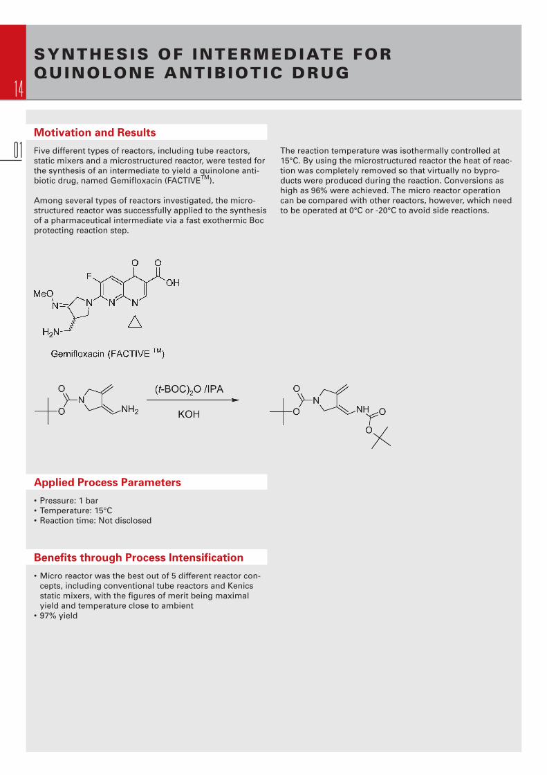
Five different types of reactors, including tube reactors, static mixers and a microstructured reactor, were tested for the synthesis of an intermediate to yield a quinolone anti-biotic drug, named Gemifl oxacin (FACTIVETM).
Among several types of reactors investigated, the micro-structured reactor was successfully applied to the synthesis of a pharmaceutical intermediate via a fast exothermic Boc protecting reaction step.
Applied Process Parameters
• Pressure: 1 bar• Temperature: 15°C• Reaction time: Not disclosed
Benefi ts through Process Intensifi cation
• Micro reactor was the best out of 5 different reactor con- cepts, including conventional tube reactors and Kenics static mixers, with the fi gures of merit being maximal yield and temperature close to ambient• 97% yield
The reaction temperature was isothermally controlled at 15°C. By using the microstructured reactor the heat of reac-tion was completely removed so that virtually no bypro-ducts were produced during the reaction. Conversions as high as 96% were achieved. The micro reactor operation can be compared with other reactors, however, which need to be operated at 0°C or -20°C to avoid side reactions.

15
NITRO GLYCERINE PRODUCTION PLANT
Motivation and Results
A continuous nitro glycerine pilot plant with microstructuredmixer/multi-tube reactors was installed at Xi’an site in Chinaand was operated at a production rate of 15 kg/h nitro gly-cerine meeting all specs. A rough calculation for annual throughput gives a production rate of nearly 130 metric tonsper year. Taking all reactants, i.e. fuming nitric acid, oleum and glycerine into account the total annual throughput is in the range of 900 cubic meters.
The main challenge for such kind of plant is to ensure safe-ty for all, even worst operational conditions. Therefore, all reactants must be pre-cooled before entering the micro-structured mixer. Also the mixer itself is actively cooled bymeans of an integrated heat exchanger as well as the multi-tubular reactor. Advanced simulations were made to solve the problems with equipartition volume fl ow through the multi-tube reactor and some new, specifi c micro-macro
interconnects for fl uid-fl ow guidance were developed and integrated. The plant is comparably small and thus, the necessary space for the plant in a safe environment, e.g. a bunker, can be reduced. The manufactured nitro glycerine will be used as medicine for acute cardiac infarction. There-fore, the product quality must be on highest grade, and thetest runs indeed revealed higher selectivity and purity. Theplant could be operated safely; one of the next targets is tohave it fully automated. As a second step, a plant for down-stream purifi cation by washing and drying the nitro glycer-ine, of notably larger size and complexity as the reactor plant, is going to be developed and currently under nego-tiation. Environmental pollution should be excluded by advanced waste water treatment. In a fi nal stage, the micro reactor nitro glycerine plant may also encompass formula-tion and packaging.
Applied Process Parameters
• Pressure: 1 bar• Temperature: 30 – 40°C• Reaction time: Some min
Benefi ts through Process Intensifi cation
• Nitro glycerine production (15 kg NG; > 100 l/h solution)• Manufactured nitro glycerine used as medicine for acute cardiac infarction• Product quality on highest grade• Plant to operate safely and fully automated• Environment protection by advanced waste water treat- ment and closed water cycle
PR
OC
ES
SE
S
01

16
BROMINATIONS OF AROMATICS AND ALKYLAROMATICS
01 0.25 to 1.00 were applied. The reactants were contacted in an interdigital micro mixer followed by a capillary reactor. At temperatures of about 200°C nearly complete conver-sion is achieved. The selectivity to the target product benzylbromide is reasonably high (at best being 85%; at 200°C and higher being 80%). The main sideproduct formed is thenitro-substituted benzal bromide, i.e. the two-fold brominatedside-chain product.
Motivation and Results
The bromination of meta-nitrotoluene is an example for ahigh-temperature, high-pressure (high-p,T) side-chain bromination of alkylaromatics.
The transformation from batch to continuous processing, the safe operation with bromine at temperatures over 170°Cand the decrease of reaction time, respectively increase of space-time yields, were drivers for the development here. Molar ratios of bromine to m-nitrotoluene ranging from
Applied Process Parameters
• Pressure: 15 bar• Temperature: 170 – 230°C• Reaction time: 2.6 min
Benefi ts through Process Intensifi cation
• Process simplifi cation: Thermal process instead of photo- chemical one• Energy savings for the latter reasons• Solvent-free process with pure bromine• Considerable speed up of reaction by high-p,T operation• Quenching of non-reacted bromine on-line and instantly after use

17
SYNTHESIS OF AN AZO PIGMENT DYE, YELLOW 12
Motivation and Results
By the use of microstructured mixers, pigment and other particle syntheses can be improved, since the well-defi nedand predictable mixing improves the preparation all the way from seed generation until particle agglomeration. In this way, fi ner particles with more uniform size distributionwere yielded for the commercial azo pigment Yellow 12.
Applied Process Parameters
• Pressure: 1 – 2 bar• Temperature: 20°C• Reaction time: A few s
Benefi ts through Process Intensifi cation
• Benefi ts through process intensifi cation• Increase of glossiness by 73% and• Increase of transparency by 66% • Better costing, since less raw material has the same effect• Easy scaling out of powder synthesis, which otherwise may be complex
The particles formed in the microstructured mixer have better optical properties such as the glossiness or trans-parency at similar tinctorial power. Since the micro mixer made pigments have more intense colour, lower contents of the costly raw material in the commercial dye products can now be employed which increases the profi tability of the pigment manufacture. P
RO
CE
SS
ES
01

18
HYDROGENATION OF NITROBENZENE
01 approached initially 100%. As side products, all intermedi-ates except phenylhydroxylamine were identifi ed. For a UV-decomposed palladium catalyst, a conversion was found slightly higher than for the sputtered one. A similar spectrum of side products as for the sputtered catalyst wasgiven. For an impregnated palladium catalyst, complete conversion was achieved and maintained for six hours. Selectivity decreased with time, but remained still at a highlevel. The best performance of all catalysts investigated wasfound for an incipient-wetness palladium catalyst. Having initially more than 90% conversion, a 75% conversion at selectivity of 80% was reached for long times on stream.
The catalyst life-time or the four types of catalysts, preparedby different preparation routes, depends on the catalyst loading which is related to the preparation route. The largerthe loading, the longer the catalysts could be used before reactivation. The four catalysts had the following sequence of life-time and activity: Wet impregnation > incipient wetness > UV-decomposition of precursors > sputtering
Several reactivation routes of the used catalyst were tested such as dissolution of organic residues by dichloromethane or burning of them by heating in air. In this way, initial acti-vity was recovered, thus regaining complete conversion.
Motivation and Results
The hydrogenations of nitro aromatics have high intrinsicreaction rates, which however cannot be exploited by conventional reactors as they are unable to cope with the large heat releases due to the large reaction enthalpies (500 – 550 kJ mol-1). For this reason, the hydrogen supply is restricted, thereby controlling reaction rate. Otherwise, decomposition of the nitro aromatics or of partially hydro-genated intermediates can occur. The hydrogenations of nitro benzene over supported noble metal catalysts were investigated in a microstructured falling fi lm micro reactor.
For nitrobenzene hydrogenation, the overall mass transfer coeffi cient kLa was conservatively estimated (based on the fi lm thickness in the middle of the channels) to be in the range 3 – 8 s-1. As a comparison, for intensifi ed gas liquid contactors kLa can reach 3 s-1, but for bubble columns and agitated tanks it does not exceed 0.2 s-1.
A wide variation of preparation procedures for the palladi-um catalyst was tested. A sputtered palladium catalyst ex-hibited low conversion and large deactivation of the cata-lyst (60°C; 4 bar). The corresponding selectivity was also low. A slightly better performance was obtained after an oxidation / reduction cycle. Following a steep initial deacti-vation, the catalyst activity stabilised at 2 – 4% conversion and at about 60% selectivity. After reactivation, selectivity
Benefi ts through Process Intensifi cation
• One of the fi rst g-l-s processes reported in microstructured reactors• Process not benchmarked in detail to batch ones
Applied Process Parameters
• Pressure: 1 – 4 bar• Temperature: 60°C• Reaction time: 5 – 20 s

19
DIRECT FLUORINATION OF TOLUENE WITH ELEMENTAL FLUORINE
While for this reason the direct fl uorination needs hours in a laboratory bubble column, it is completed within secondsor even milliseconds when using a miniature bubble col-umn, operating close to the kinetic limit. Favourable elec-trophilic substitution is achieved, showing that unselective radical paths are largely absent. The overall selectivity of this non-optimised process amounts to about 25%, not far from the total selectivity of all the Balz-Schiemann steps to achieve the same result. Waste reduction is less since a single step synthesis is undergone. Productivity is much higher, as demonstrated by the order of magnitude larger space-time yields.
Motivation and Results
One way of process simplifi cation is to make molecular com-plex compounds out of much simpler building blocks (e.g. by multi-component one-pot syntheses like the Ugi reac-tion), at best directly out of the elements. Especially in thelatter case, this is often quoted as “dream reaction“. Typi-cally, such routes have been realised so far from hazardouselements, easily undergoing reaction, but lacking of selec-tivity. One example for this is the direct fl uorination starting from elemental fl uorine which was performed, e.g., with toluene.
Since the heat release cannot be controlled with conven-tional reactors, the process is deliberately slowed down.
Applied Process Parameters
• Pressure: 3 – 20 bar• Temperature: 20 – 90°C• Reaction time: 2 – 30 min
Benefi ts through Process Intensifi cation
• Reduction of reaction time up to ~ 1000• Increase in space-time yield by factor 10,000• Increase in productivity by factor 5• Single-step operation replaces tedious Balz-Schiemann route• Less waste generation• Less reactor investment and process simplifi cation
PR
OC
ES
SE
S
01

20
SULPHONATION OF TOLUENE
01Motivation and Results
Toluene is heated up to 40°C using a microstructured heatexchanger while at the same time liquid sulphur trioxide isheated up to 60°C in order to evaporate it. Nitrogen is furtheradded so as to dilute the system and the stream is then passed into a separator with the purpose of removing any traces of liquid. Thus, a gas stream is allowed to fl ow through to a micro- structured reactor where it reacts with the liquid toluene. As shown in reaction (1), sulphonic acid is produced here via the desired reaction step. At the same time, though, sul-phone (reaction (2)), a mixed anhydride and sulphonic acid anhydride are also formed by side reactions. Sulphone cannot be converted further but the mixed anhydride reacts in the residence time module with toluene and forms the desired product, sulphonic acid, as shown in reaction (3). To convert the sulphonic acid anhydride to sulphonic acid, a hydration step is required (reaction (4)). To achieve this, water is added to the reaction mixture after the residence time module.
Up to date, the reaction has been carried out up until the residence-time module. The fi nal hydration step has not
Benefi ts through Process Intensifi cation
• One of the fi rst complex micro-fl ow process designs for a multi-step synthesis• Better para-isomer selectivity
Applied Process Parameters
• Pressure: 1 bar• Temperature: 40°C• Reaction time: 5 – 15 s
taken place. Even so, fi rst results are encouraging. In order to evaluate reaction conditions, the mole ratio of the two reactants, sulfur trioxide and toluene, was varied and the selectivity of the desired product (sulfonic acid) and of the by-products (sulfon and the anhydride mixture) was deter-mined. Evidently, with increasing SO3/toluene mole ratio, the selectivity of the undesired by-products decreases whilethe selectivity of sulfonic acid stays nearly constant. At a mole ratio of 13/100, the selectivity of sulfonic acid is approximately 80% while that of sulfone decreases to approximately 3% and that of the sulfonic acid anhydride to approximately 1.3%.
The isomer selectivity was also determined to be 8.1% for the ortho-sulphonic acid, 1.5% for the meta-sulphonic acid and 90.4% for the para-sulphonic acid. From literature, at a SO3/toluene mole ratio of 13.4, the selectivity of the ortho-sulphonic acid was 17.6%, of the meta-sulphonic acid 1.2%and that of the para-sulphonic acid was 81.2%. Thus the improvement of the selectivity for the para-sulphonic acid can already be seen from these results. Very recently also the last hydration step was executed successfully.

21
DIRECT HYDROGEN PEROXIDE SYNTHESIS OUT OF THE ELEMENTS
Motivation and Results
Several examples were reported for conducting routes in the explosive regime. Among them and most prominent was the detonating-gas reaction, using pure hydrogen and oxygen mixtures. This stands for a direct route from the elements. With special catalysts hydrogen peroxide, and not water, is obtained as value product, avoiding the circui-tous Anthraquinone process, used at industrial scale.
Calculations of explosion limits clearly demonstrate that there is a considerable shift, when explosive reactions are carried out in micro channels. The safety is not only related to avoiding thermal runaway, but relates to mechanistic rea-sons by breaking the radical chain by enhanced wall colli-sion in the small channels with their large specifi c interfaces.
Using this direct route to hydrogen peroxide, basic engineer-ing for a new site for the production in the order of about 150,000 t hydrogen peroxide per year was done by UOP. Pi-lot processing and economic calculation of the production process has been performed. Based on microstructured
mixing units, the new process is realised by direct contact-ing of hydrogen and oxygen (without inert gas) in the pres-ence of a heterogeneous catalyst. The key to a high selec-tivity is to have a noble-metal catalyst in a partially oxidisedstate. Otherwise, only water is formed or no reaction is achieved. Peroxide testing at IMM used such a hydrogen peroxide selective catalyst placed within a mini-trickle bed reactor equipped with a micro mixer. Using UOP process specs, a space-time yield of 2 g hydrogen peroxide per g catalyst was achieved which exceeds literature values. In addition, operation at only 20 bar, considerably lower than for the published processes, and usage of smaller oxygen/hydrogen ratios, saving valuable raw materials, is given. It could be clearly shown that improved selectivity and conversion is given at explosive oxygen/hydrogen ratios. UOP then carried out pilot-scale tests at other pressures in a fully automated explosion cell to reproduce vendor work and to study conditions and kinetics. A selectivity as high as 85% at 90% conversion was achieved so far (oxy-gen/hydrogen ratio of 1.5 – 3).
Benefi ts through Process Intensifi cation
• Reduction of system pressure by factor 4, from 120 to 30 bar• Increase in space-time yield by 25%, from 1.5 to 2.0 g h/gcat
• Favourable decrease in oxygen to hydrogen ratio by factor ~ 4, from 6.8 to 1.5 (OPEX costs)• Safe operation at all oxygen to hydrogen ratios in the explosive envelope• Full cost analysis for world-scale plant (162kMTA) with improved OPEX costing• 78% selectivity
Applied Process Parameters
• Pressure: 30 bar• Temperature: 50°C• Reaction time: A few s
PR
OC
ES
SE
S
01

22
[4+2] CYCLOADDITION OF SINGLET OXYGEN TO CYCLOPENTADIENE TO MAKE CYCLO-PENTENE-1.4 -DIOL
01 Low-intensity light sources should give effi cient irradiation of thin liquid layers. Sample heating is reduced and so is radical recombination. In addition, oxygen-enrichment of solutions before and after micro reactor passage can be handled differently and is no longer a major safety problem.
For the oxidation of cyclopentadiene by singlet oxygen to 2-cyclopentene-1.4-diol a yield of 19.5% was found. The feasibility of safely carrying out the oxidation of cyclopenta-diene by singlet oxygen to 2-cyclopentene-1.4-diol was de-monstrated. The explosive intermediate endoperoxide was generated and without isolation used on-site for a sub-sequent hydration reaction.
Motivation and Results
This reaction of industrial interest utilises singlet oxygen generated by irradiation in the presence of Rose Bengal. An endoperoxide is formed as intermediate which is converted to 2-cyclopentene-1.4-diol by reduction with thiourea.
Due to the small length scales in micro reactors, e.g. 50 µm,high concentrations of a sensitizer may be used. As these materials typically have high costs, recycle loops with low inventory can be employed to consume only a low overall amount of sensitizer. The sensitizer absorption, despite the large molar extinction coeffi cient, is not over the tolerablelimit since only small optical paths are employed. It is as-sumed that molecules in thin liquid layers face a broadly similar photon fl ux, unlike macro-scale photo processing.
Benefi ts through Process Intensifi cation
• High quantum effi ciency• Safe on-site conversion of endoperoxides generated• Reduction of energy consumption• Use of high sensitizer concentration• Reduced thermal overshooting of sample due to lowering light intensity
Applied Process Parameters
• Pressure: 1 bar• Temperature: 0 – 15°C• Reaction time: 5 – 20 s

23
SIDE-CHAIN PHOTOCHLORINATION OFTOLUENE-2.4 -DI - ISOCYANATE
Motivation and Results
Side-chain photochlorination of toluene isocyanates yieldimportant industrial intermediates for polyurethane syn-thesis, one of the most important classes of polymers. The motivation for micro channel processing stems mainly fromenhancing the performance of the photo process. Illumi-nated thin liquid layers should have much higher photon effi ciency (quantum yield) than given for conventional pro-cesssing. In turn, this may lead to the use of low-intensity light sources and considerably decrease the energy con-sumption for a photolytic process.
Due to the planar layer structure of most micro reactors a uniform illumination is yielded in addition, which can be kept when increasing throughput by numbering-up. Here, the individual reaction units are assembled in parallel again on a plane, only a larger one.
By using a nickel plate, space-time yields up to 401 mol/(l h)were achieved in the Falling Film Micro Reactor. Control ex-periments in a batch reactor at 30 min reaction time result-ed in a space-time yield of only 1.3 mol/(l h), hence are by orders of magnitude smaller. By using an iron plate, space-time yields up to 346 mol/(l h) were achieved in the Falling Film Micro Reactor.
Conversions from 30% to 81% at selectivities from 79% to67%, respectively yields from 24% to 54%, were found whenusing a Falling Film Micro Reactor (4.8 – 13.7 s; 130°C). Control experiments in a batch reactor (30 ml reaction vol-ume) at 30 min reaction time resulted in a conversion of 65% at 45% selectivity, hence having a selectivity which is higher by about a factor of 2.
Benefi ts through Process Intensifi cation
• High quantum effi ciency• Increased selectivity, 79% instead of 45% for batch• Increased conversion, 81% instead of 65% for batch• Increased space-time yield by two orders of magnitude, 401 mol/(l h) instead of 1.3 mol/(l h)• Reduction of energy consumption• Reduced thermal overshooting of sample due to lowering light intensity
Applied Process Parameters
• Pressure: 1 bar• Temperature: 130°C• Reaction time: 5 – 15 s
PR
OC
ES
SE
S
01

24
02
PLANTS
24
25
CONTENTS> p l a n t s m a d e b y i m m
PL
AN
TS
02
Plants
Organic Synthesis Plant OSBP 26
Impinging-Jet Microreactor Plant for Precipitation Reactions IJMP 28
Cream and Emulsifi cation Plant CSBP 30
Modular Microreactor Systems for Production Plants 32
Falling Film Micro Reactor Plant FFMR-BSP 34
Gas Phase Reactor Test Plant 36
Fuel Processor Demonstration Plant 38
Mixer-Settler Continuous Work-Up Plant CWUP 40

26
ORGANIC SYNTHESIS PLANTOSBP
02
OSBP for 2-step reaction
Principle
In micro reactor literature, the most frequently used approach for organic synthesis is the micro mixer/tube reac-tor. The organic synthesis bench-scale unit relies on this concept and has inaddition control and measuring func-tions. It is based on the reliable hybrid concept of IMM, utilizing innovative micro reactor components in connec-tion with well-proven conventional small-fl uidic equipment. IMM has gain-ed huge experience with carrying outorganic reactions e.g. ethoxy silylations, metal-organic syntheses, and epoxida-tions in such micro mixer/tube reactor bench-scale units. As a result this unit concept was developed and tested to yield the bench-scale unit actually of-fered now. It comprises two pre-heat-ing loops (as option: microstructured heat exchangers), a micro mixer, a 5/2-way valve, and 4 delay loops ofdifferent length collected to one outletwhich allows to change the residence time for a given set of parameters dur-ing the reaction by simply switching the valve. On demand, the general bench-scale unit concept can be modi-fi ed towards more complex design.The concept is amenable to supercrit-ical processing as well.
OSBP for single-step reaction (top view)
OSBP for single-step reaction (inside view)

27
Typical fl ow charts for Organic Synthesis Plant
Pilot-scale plant for nitro glycerine production
Operating Conditions
Temperature (°C) -50 – 180
Pressure stability (bar) 30 for stainless steel 3 for PTFE
Flowrate (l/h) 0.05 – 2.5 for mixer SIMM-V2 2.5 – 30 for mixer CPMM-V1.2-R600/12
Residence time (s) 4 changeable delay loops have a different length of approx. 1%, 5%, 20% and 100% (the absolute lengths will be adjusted to the applied mixer to yield reasonable residence times) Leakage Class L0.1
Specifi cation of the Basic System
• 2 pre-heating loops (as option: Microstructured heat exchangers)• 1 SIMM-V2-mixer or 1 CPMM-mixer with housing material stainless steel • 4 delay loops with different residence times, switchable online via a 5/2-way valve • 1 tube-in-tube heat exchanger (as option: Microstructured heat exchanger) at the outlet• All above devices mounted on a metal plate• Assembled set-up fi ts into a heating bath
Options
• Temperature and pressure measurement unit • Pumping units • Process control unit, programmed in LabView• Other materials on request
Further Applications
Based on the IMM knowledge on general demands for a chemical synthesis plant, this basic set-up was designed. Though it should be directly applicable for many typical (organic) syntheses i.e. for gas/liquid or liquid/liquid mixing homogenuously or dispersing (emulsions, foams), even catalyst slurries might be processed. If the standard version is not suffi cient, it might be differentiated and/or extended where needed, e.g. for multi-step processing. Insofar, this set-up represents a versatile tool to directly enter into micro chemical process engineering.
PL
AN
TS
02

28
IMPINGING-JET MICROREACTOR PLANTFOR PRECIPITATION REACTIONS IJMP
02Main part of the IJMP with mixing chamber and heat exchangers
The balance system for mass fl ow control combined with gear pumps as well as the process control system is not shown here
Principle
The Impinping-Jet Microreactor Plant IJMP is the logical advancement of the Organic Synthesis Bench-Scale Plant OSBP for precipitation reactions which cause blockage by main or side products and cannot be processed in our standard OSBP. The delay loop was removed and the remaining blocking sensitive part, the mixer, substituted by the simplest non-fouling component for continuous mixing-processing, the Impinging-Jet Micromixer IJMM. Educt streams are tempered via two microstructuredheat exchangers HX204 before entering the mixer, enabling a fast and effi cient temperature control.
The overall pressure and tempera-ture stability is mainly limited by the windows and gasket of the mixing chamber. The position of the IJMM in the mixing chamber can be adjusted in the vertical direction which allows best fi tting connection of an outleav-ing (reaction) tube downstream, in case the mixing section tends to spraying causing contamination of the mixing chamber. Additional (inert) gas fl ushing is integrated.
Another option is to use the Sep-aration Layer Interdigital Micromixer SLIMM instead of IJMM to carry out precipitations.

29
nitrogen
nitrogen thermostat
nitrogen
Operating Conditions
Temperature (°C) -200 °C to + 250 °C @ 1 bar Pressure stability (bar) 0 - 40 bar @ 25 °C
Flowrate (l/h) depending on used mixer, for IJMM-350 e.g. 1.4 – 3.0 l/h watery fl ow
The process control system of the Impinging-Jet Micro-reactor Plant IJMP allows for both educt fl ows the exact mass fl ow regulation with gear pumps and balances as well as measuring and controlling their inlet temperature into the mixing chamber. Besides complete data acquisition including system pressure this LabView-based system can run given programs (e.g. overnight experiments) easily compiled with the integrated program editor. The collected data are as ASCII-fi les easily importable e.g. into Excel for further use.
Flow chart of the IJMP including balance system
PL
AN
TS
02
The mixing chamber with height-adjustable IJMM inside
The LabView-based process control system for the IJMP
Technical Data
Name Impinging-Jet Microreactor Plant Order number IJMP
Size (L x B x H) main part depicted left: approx. W 50 cm x H 80 cm x D 30 cm Connectors (Inlet/Outlet) 1/4˝ / 1/4˝ Standard material Housing, mixer: 1.4571 Glass Standard mixing channels (µm) depending on used mixer, typically for IJMM: 350 µm diameter
Options Other materials like Hastelloy, Monell or Titan on request

30
CREAM AND EMULSIF ICATION PLANTCSBP
02
Cream Synthesis Bench-Scale Plant for 5 different chemicals
Cream Plant positioned on a holder for easy maintenance, cleaning and device exchange
Principle
Generating emulsions is typically a process where all materials are being balanced or measured, placed in a fl askor vessel and then vigorously stirred or homogenised with high energy con-sumption. Micromixers insofar proved in literature to reduce energy input byfactor 10. Besides, more narrow drop-let size distribution can be achieved within a shorter time as conventionaltechniques as only passing once through within milliseconds yields the result. Further taking the advantage of small hold-ups despite the pilot-scale productivity, a versatile tool concept is offered herewith enabling even a fast change of cream recipes within less than a minute. Respectively, a multi-tude of different pastes, creams, lotionswithin short time can be produced as samples or in larger amounts.
The CSBP-Demonstrator is based on the reliable hybrid concept of IMM,utilizing innovative microreactor
components in connection with well-proven conventional small-fl uidic equipment. Respectively, small gearring pumps for max. to 1 – 15 l/h de-pending on type and 140°C are used to convey up to 4 liquids and 4 solids being molten in the comprised heat bath into a mixer array as the 8 Com-ponent Caterpillar Micromixer (8CCPM) directly yielding the hot emulsion. The 4 solid components can be fed via temperature-controlled heated funnels into tempered fl ask whereof being pumped, enabling a full continuous processing even in case of production need. The liquids are heated up with simple heating loops, bath-fed or electrically drivenheat exchangers depending on total fl ow rate need.
The general bench-scale unit concept can be modifi ed towards more com-plex design. The concept is amenable to unusual processing as well.

31
Cream Synthesis Plant or 4 solid and 4 liquid educts and continous use
Cream Synthesis Plant for 1 solid and 1 liquid educt and continous use
Array of 3 CPMM to mix 4 components nearly at once, 4CCPM, ca. 3-60 l/h
Seven CPMM structures to mix 8 components, of PMMA, 8CCPM
Operating Conditions
Temperature (°C) 20 – 140
Pressure stability (bar) 20 for stainless steel 3 for PTFE
Flowrate (l/h) 2.5 – 60
Leakage Class L0.1
Specifi cation of the Basic System
• Up to 8 electrical pre-heating storage tanks • Eightfold-CPMM-mixer with housing material stainless steel or PTFE • Micro annular gear pumps• All above devices mounted on a metal plate• Assembled set-up fi ts into a heating bath
Options
• Temperature and pressure measurement unit • Process control unit, programmed in LabView• Other materials on request
PL
AN
TS
02
Special StarLaminator10, to mix 3 components at once, ca. 5-80 l/h
31

32
MODULAR MICROREACTOR SYSTEMS FOR PRODUCTION PLANTS
02
Exemplary basic unit of a Modular Microreactor System consisting of distributor, three reaction modules and collector
Confi guration with heat exchangers (HX-series), tempered caterpillar mixer (CPMM-V1.2-HEX), distributor,reaction module and collector
Principle
Recent R&D efforts led to the devel-opment and realisation of modular microreactor based systems for production plants. The concept was developed to execute reactions which benefi t from the outstanding properties of microstructured devices, especially concerning heat transfer and mixing. Mainly for fi ne and specialty chemistry reactions the size of the modules allows scaling up processes up to the production scale. The basic unit thereby consists of newly developed, fl angeable modules made of stainless steel. The modules are manufactured of vacuum brazed microstructured plate stacks which can withstand higher pressures. Each basic unit is composed of a distributor module
which spreads the feed stream to all channels of the stack, a variable number of reaction modules with integrated heat exchanger function and a subsequent collector module. Each module can be tempered on its own temperature level if required. This basic unit can then be extended to an overall modular system following the multiscale approach, e.g. the microstructured modules can be followed by a mini-scale multi-tube reactor which exhibits suffi cient heat transfer properties to complete the reaction. The basic units can furthermore be supplemented with microstructured heat exchangers, e.g. of the HX or WT series, and micromixers, e.g. of the CPMM-V1.2 or of the StarLam series.

33
Flow chart of a typical confi guration of a modular microreactor system for production plants
Distributor/collector moduleVacuum brazed reaction module with open reaction channels
Multi-tube module
Operating Conditions (exemplary)
Temperature (°C) + 200 °C @ 50 bar (higher temperature on request)
Pressure stability (bar) 50 bar @ 200 °C (higher pressure on request)
Flowrate (l/h) depending on the reaction, module system e.g. 1 to 10 (more upon request)
PL
AN
TS
02
Basic unit and subsequent multi-tube module
0.0
0.2
0.4
0.6
0.8
1.0
0.0 0.5 1.0 1.5 2.0
Θ=t/τ[-]
F (Θ
)
0.0
0.5
1.0
1.5
2.0
2.5
3.0
3.5
4.0
E(Θ
)
Bo = 90
E(Θ)
F(Θ)
Normalised residence time distribution function for a basic unit with 2 reaction modules at 3 l/h fl owrate
reactant 1
reactant 2
heat transfer medium
micromixer
micro heatexchanger
micro heatexchanger
micro heatexchanger
heat transfermedium
heat transfermedium
heat transfermedium
heat transfermedium
heat transfermedium
heat transfermedium
coolant
product
distributormodule
flangeable basic unit
microstructuredreaction module
microstructuredreaction module
microstructuredreaction module
collectormodule
R(n+1)conventional(multi) tubereaction module
heat transfer medium
33

34
FALLING F ILM MICROREACTOR PLANTFFMR-BSP
02
Falling Film Micro Reactor Plant
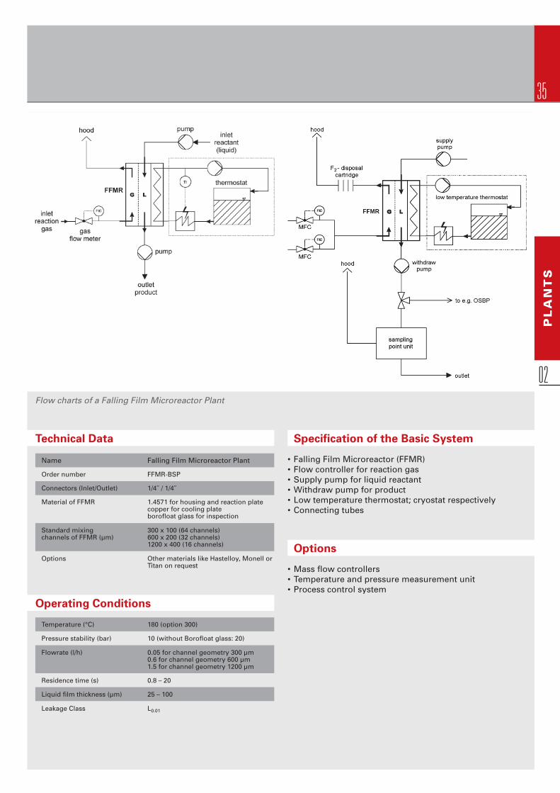
Operation in the Falling Film Microre-actor device can be performed up to 300°C at a pressure of max. 10 bar by using the standard version (upper housing with inspection glass) or max. 20 bar with the special upper housing without window. The suitable liquid fl ow rates depend on the channel ge-ometry of the corresponding reaction plate and the property of the reactant (e.g. viscosity). For example, the max. liquid fl ow rate by using isopropanol and a channel size of 1200 µm x 600 µmis 1.5 l/h.
Principle
The Falling Film Microreactor Bench-Scale Plant comprises besides the Fall-ing Film Microreactor, a mass fl ow controller for the gas fl ow, a cryostat, a supply- and a withdraw-pump for theliquid fl ow. The precise assortment of the peripheral equipment components basically depends on the different chemical reactions which the cus-tomer wants to perform. This means, the general bench-scale unit concept can be modifi ed towards more com-plex design.
35
Flow charts of a Falling Film Microreactor Plant
Operating Conditions
Temperature (°C) 180 (option 300)
Pressure stability (bar) 10 (without Borofl oat glass: 20) Flowrate (l/h) 0.05 for channel geometry 300 µm 0.6 for channel geometry 600 µm 1.5 for channel geometry 1200 µm
Residence time (s) 0.8 – 20
Liquid fi lm thickness (µm) 25 – 100
Leakage Class L0.01
Technical Data
Name Falling Film Microreactor Plant
Order number FFMR-BSP
Connectors (Inlet/Outlet) 1/4˝ / 1/4˝
Material of FFMR 1.4571 for housing and reaction plate copper for cooling plate borofl oat glass for inspection Standard mixing 300 x 100 (64 channels) channels of FFMR (µm) 600 x 200 (32 channels) 1200 x 400 (16 channels) Options Other materials like Hastelloy, Monell or Titan on request
PL
AN
TS
02
Options
• Mass fl ow controllers• Temperature and pressure measurement unit• Process control system
Specifi cation of the Basic System
• Falling Film Microreactor (FFMR)• Flow controller for reaction gas• Supply pump for liquid reactant• Withdraw pump for product• Low temperature thermostat; cryostat respectively• Connecting tubes

36
GAS PHASE REACTOR TEST PLANT
02
Bench-scale catalyst evaluation unit for fossil and alcohol fuel processing
Principle
This bench-scale unit serves for inves-tigations in heterogeneous catalysis with respect to fossil fuel and alcoholfuel processing, e.g. concerning thedetermination of the activity/selectivityand stability of catalysts, as well as process optimization studies of this class of gas-phase reactions by fast serial variation of process parameters such as temperature, pressure, gas fl ow velocity, and gas composition.The bench-scale unit comprises com-mercial mass-fl ow controllers for con-trol of the gas feed, fl ame arresters tostop fl ame propagation, and a micro-structured evaporator fed by a liquid
tank, which produces steam or organicvapours (optional), all mounted on a metal board. Steam and gas feed are mixed and enter a micro device composed of two laser-welded micro- structured platelets having one inlet and outlet tube, also welded to the two-platelet stack. Operation in the micro device can be performed up to900°C at a pressure of 10 bars, using external resistance heating. The cata-lyst is usually introduced into the microchannels prior to interconnection, e.g. by the wash-coat route and subsequentimpregnation. By laser-welding the thermal treatment is spatially confi ned
so that the catalyst is not destroyed during interconnection. The welded micro device can be cut after use so that analytical studies can be carried out with the catalyst layers that were exposed to the reactants during time on stream.
Besides using the two-platelet stack micro reactor, any other IMM or other-source micro reactor can be integratedinto this bench-scale unit. In this case,please contact IMM prior to the con-struction of the bench-scale unit so that the required modifi cations can be arranged.

37
In conjunction with bench-scale unit construction, IMM ser-vices include provision of a manual which contains, besides general information, detailed documentation on experiencesgained with operation of this bench-scale unit. Exemplarily, operational modes are given so facilitating the fi rst experi-mental steps when starting bench-scale unit operation. Incase of further questions and desires, an IMM contact per-son can be consulted by mail or phone.
By special request, a process parameter monitoring pro-gram based on the LabView software can be supplied that allows automatic acquisition of temperature and pressure data.
The bench-scale unit was in detail investigated not only for numerous steam reforming and partial oxidation reactions of alcohol and hydrocarbon fuels, but also for CO clean-up such as water-gas shift, preferential oxidation and meth-
anation. Besides constructional changes in the set-up, this requires the coating of another catalyst. IMM has in particu-lar gained experience in building bench-scale units for all kind of fuel processing unit operations and in operating respective micro devices. An extension of the use of bench-scale units for other types of heterogeneous catalytic studiesis principally possible and requires in most cases only minormodifi cations of the bench-scale unit construction. Here, information on the exact process desired is required from the customer and a special offer will be prepared by IMM.
The performance of the reforming bench-scale unit was demonstrated in detail for propane steam-reforming, meth-anol and ethanol steam-reforming, partial oxidation of pro-pane, water-gas shift at high and low temperature, preferen-tial oxidation of carbon monoxide, and for the methanation of carbon monoxide.
PL
AN
TS
02
Options
• Additional mass-fl ow controllers (e.g. for air, oxygen)• Additional periphery heating (pipes)• Additional liquid storage tanks (required for long term operation)• Additional temperature sensors
Specifi cation of the Basic System
• Mass fl ow controllers for hydrogen, nitrogen, hydro- carbons, carbon monoxide, carbon dioxide, air and water (choice of selection optional)• Stainless steel vessels for water and organic liquids• Evaporator• Valves, manometers, fl ame arresters• Temperature controllers• Pressure controller (optional) • All above devices mounted on a metal frame• Available IMM-reactors for testing catalyst performance

38
FUEL PROCESSOR DEMONSTRATION PLANT
02
Principle
This test bench serves for investiga-tions in reactor performance testing with focus on fuel processing applica-tions such as fossil and alcohol fuel reforming and catalytic CO-clean-up. The unit is designed for tests of start-up, steady-state and transient reactor behaviour and for long-term tests. Process optimization studies may be performed, if serial combinations of several reactors (e.g. reforming, water-gas shift and preferential oxida-tion reactors) are integrated into the unit. Fast serial variation of process parameters such as temperature, pressure, gas fl ow velocity, and gas composition are possible.
Test bench for single reactors and multiple reactor arrangements
The test bench comprises commercialmass-fl ow controllers for control of thegas feed, fl ame arrestors to stop fl ame propagation, and various evaporator types (evaporation power between 10 s of watts up to kilowatts). The evapor-ator, which is fed by a liquid tank, pro-duces steam or organic vapour. All devices are mounted onto a metallic frame. Steam and gas feed are mixed and enter the reactor, which may be a microstructured device or a conven-tional reactor type (metallic monolith or fi xed bed reactor). Operation in themicrostructured reactors may be per-formed up to 900°C at pressures of upto 5 bars, for maximum temperature
of 500°C at pressures up to 100 bars, using either external resistance heat-ing or integrated catalytic burners. Also internally cooled reactors (heat exchangers) and combinations of thesereactor types may be tested in the test bench. By-pass lines are introduced, thus allowing for switching off the in-dividual reactors under test. The cata-lyst is usually introduced into the microchannels prior to the sealing procedure(normally laser-welding), e.g. by the wash-coat route and subsequent im-pregnation. By laser-welding the ther-mal treatment is spatially confi ned so that the catalyst is not destroyed during interconnection.
39
Please contact IMM prior to the construction of the test bench so that the modifi cations required can be arranged.
In conjunction with test bench construction, IMM servicesinclude provision of a manual which contains, besides gen-eral information, detailed documentation on experiences gained with operation of this bench-scale unit. Exemplarily, operational modes are given so facilitating the fi rst experi-mental steps when starting bench-scale unit operation. In case of further questions and requests, an IMM contact per-son can be consulted by mail or phone.
By special request, a process parameter monitoring programbased on the LabView software can be supplied that allowsautomatic data acquisition of temperature and pressure.
The bench-scale unit was in detail investigated for steam-reforming and autothermal reforming of fossil fuels, for water-gas shift and for the preferential oxidation of carbon monoxide, all up to the 10 kW range (lower heating value of the hydrogen produced/processed), however it may – on special customer request – be modifi ed to allow for in-vestigations of other types of heterogeneous gas-phase reactions. Here, information on the exact process desired is required from the customer and a special offer will be prepared by IMM.
Operating Conditions
Max. pressure (bar) 10 Max. reservoir of water or organic 20 liquid for one continious run (l) Max. fl owrate (gas) approx. (Nl/min) about 500
Max. fl owrate (liquid) approx. (g/h) about 5000 Max. evaporator temperature (°C) 200
PL
AN
TS
02
Options
• Additional massfl ow controllers (e.g. for air, oxygen)• Additional periphery heatings• Additional liquid storage tanks• Additional temperature and pressure sensors
Specifi cation of the Basic System
• Mass fl ow controllers for hydrogen, nitrogen, hydro- carbons, carbon monoxide, carbon dioxide, air and water (choice of selection optional)• Stainless steel tanks for water and organic liquids• Evaporators • Temperature controllers• Pressure controller (optional) • Valves, manometers, fl ame arresters • All above devices mounted on a metal plate• Available Reactors

40
Specifi cation of the Basic System
• Three settlers (glass tube and siphons)• Two Caterpillar Micromixers• Two + two gear pumps• Four fi lling level sensors• Filling level-fl ow rate controller• Lab hood-like housing with transparent doors
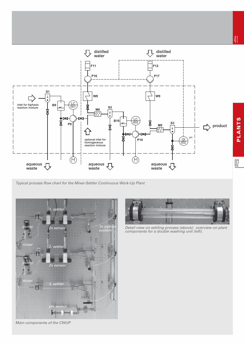
MIXER-SETTLER CONTINUOUS WORK-UP PLANTCWUP
02Principle
Against the background of a two- phase liquid/liquid reaction performed in a microreactor based set-up, IMM has developed a matching Continuous Work-Up Plant. This plant consists of a combination of mixers and settlers to cover the functionality of inital phase separation and of two washing steps with water for the organic phase.
A biphasic reaction mixture (e.g. organic phase and aqueous phase) is separated by an initial, gravity driven mini-settler. In the next step, the organic phase is contacted with an aqueous washing phase via a Cater-pillar Micromixer and separated subsequently in a second settler. In the third step, the same procedure is repeated.
One settler-unit is composed of a glass tube, attached with special fi ttings on both ends. The fl ow of the organic phase in the two washing steps is automatically regulated by gear pumps based on the measure-ment by special fi lling level sensors. The water level in a settler is adjusted by a fl exible tube siphon. A sensor is measuring the pH-value of the waste aqueous phase of the second washing step and thereby monitoring washing success of the organic phase. Based on this the fl ow rate of the aqueous phase is adjusted automatically.
CWUP; separation of an incoming biphasic system and subsequent 2-step washing with micromixer-settler-siphon system.
Operating Conditions
Total fl ow rate up to 150 ml/min Operating pressure atmospheric
Temperature up to 80°C
41
PL
AN
TS
02
distilled water
optional inlet for homogeneous reaction mixture
inlet for biphasicreaction mixture
distilled water
product
aqueouswaste
aqueouswaste
aqueouswaste
Typical process fl ow chart for the Mixer-Settler Continuous Work-Up Plant
Main components of the CWUP
Detail view on settling process (above); overview on plant components for a double washing unit (left).
1. settler
2x sensor
2. settler
2x sensor
3. settler
pH-sensor
pump
mixer
pump
mixer
3x siphon system

42
03
COMPONENTS
42

43
CONTENTS> c o m p o n e n t s m a d e b y i m m
CO
MP
ON
EN
TS
03
Components
Liquid/Liquid and Gas/Liquid Mixers or Reactors
Overview Applications 44
Mixing Principles 45
Caterpillar Split-Recombine Micromixer CPMM-V1.2 group class-R150, -R300, -R600, -R1200, -R2400 46
Star Laminator StarLam group class -30, -300, -3000, -30000 50
Slit Interdigital Micromixer SIMM group class SIMM-V2, HPIMM, SIMHEX, SSIMM 54
Liquid/Liquid Microreactor LLMR-MIX 58
SuperFocus Interdigital Micromixer SFIMM-V2 60
Impinging-Jet Micromixer IJMM 62
Special Gas Liquid Reactors
Falling Film Microreactor FFMR 64
Gas Phase Reactors
Gas Phase Microreactor GPMR 68
Gas Phase Microreactor with Mixer and Internal Heating/Cooling GPMR-Mix 70
Catalyst Micro Burner Reactor CMBR 72
Catalyst Testing Microreactor CTMR 74
Heat Exchangers
Laser-welded Micro Heat Exchanger WT-series 76
Brazed Micro Heat Exchangers HX-series 78
Tube Heat Transfer Micro Device THTMD 80
Laboratory Evaporator 82

44
03Applications Type of Standard Mixers and Reactors Application Examples Liquid/liquid and gas/liquid reactions SIMM, CPMM, StarLam, SFIMM-V2 • Grignard reaction • Kolbe-Schmitt synthesis • Sonogashira couplings • Formation of polyacrylates • Formation of blockcopolymers • Phenyl boronic acid synthesis • Benzal chloride hydrolysis • Dendrimer synthesis • Michael reaction • Nitro glycerine synthesis • Bromation of alkylaromatics with elemental bromine • Synthesis of (S)-2-Acetyl-tetrahydro- furan (antibiotic drug intermediate) • Synthesis of an intermediate for Gemifl oxacin (FACTIVETM) • Isomerisation of allyl alcohols • H-transfer reduction of citraconic acid ester • Aromatic nitrations • Aliphatic nitrations
Special gas/liquid reactions FFMR, MBC, SIMM, CPMM and StarLam • Direct fl uorination of toluene • Sulfonation of aromatics • Hydrogenation of nitrobenzene • Hydrogenation of cinnamic acid esters
Reactions at high pressure HPIMM • Alkylation of aromatics with supercritical CO2 • Direct H2O2 synthesis
Dispersion and emulsion formation SIMM, CPMM, StarLam • Mixing of silicon oil and water • Mixing of diesel and water
Mixing of liquids differing in viscosity SFIMM-V2, SIMM, StarLam • Addition reaction with liquid ethylene oxide synthesis
Photochemical reactions Produced with window: • [2+2] Diels Alder photooxygenation SFIMM-V2, FFMR, MBR of olefi nes • Photochemical chlorination of alkylaromatics Reactions with catalytic suspensions CPMM • Hydrogenation of C=C double bonds
Particle and pigment synthesis
Inorganic particles SSIMM, CPMM, IJMM, SLIMM • Titanates (precipitation) • CaCO3 (precip.) • Au (GNP), Pt/C (reduction) • {N-doped TiO2 (hydrothermal process)}
Organic particles SSIMM, CPMM, IJMM, SLIMM • Bipyridine (precipitation) • Starch (dispersion + solidifi cation)
Pigments SSIMM, CPMM • Azopigment Yellow 12 (precipitation) • Azopigment Clariant (precipitation)
Polymer particles HPIMM, SSIMM, CPMM • Polystyrene (dispersion + solidifi cation)
Microcapsules SSIMM, CPMM • Model prot. PSA-in-LGPA (disp. + solid.) • Nanocomp. - Steroids (disp. + solid.)
Amphiphilic particles SSIMM • Stearate/phenofi brate (self-assembly) • Amphiphilic vesicles (self-assembly) • Block copolymer vesicles (self-as.)
OVERVIEW> a p p l i c a t i o n s
44

45
CO
MP
ON
EN
TS
03
Co
nstr
ucti
on
al
pri
ncip
les
Pro
du
ct
cla
sse
sP
rod
ucts
Split-recombine Multi-lamination Jet collision
Ramp-up/downInterdigital
disk array
Caterpillar
CPMMStar Laminator
StarLamImpinging-jet
IJMM
TriangularSlit
Standard
SSIMM
Version 2
SIMM-V 2
Heat Exchanger
SIMHEX
High-Pressure
HPIMM
Tilted jetsInterdigital channel array
Multi-lamination Jet collision
Interdigital
disk array
Caterpillar
CPMMStar Laminator
StarLamImpinging-jet
IJMM
Triangular
Super-Focus (V2)
SFIMMSuper-Focus (V2)
SFIMM
Slit
Standard
SSIMM
Version 2
SIMM-V 2
Heat Exchanger
SIMHEX
High-Pressure
HPIMM
Tilted jetsInterdigital channel array
> m i x i n g p r i n c i p l e s b y i m m
CPMM R150/12 (0,1l/h - 1,0l/h)
45
Bas-reliefBas-relief
RecirculationRecirculation

46
Principle
The Caterpillar Micromixers are partic-ularly suitable for applications where fast mixing at higher throughput is de-sired, providing highest performance for l/l-mixing as well as for g/l- or l/l- dispersing. As they consist of a struc-tured single channel, these devices may also be used successfully if preci-pitation occurs during the reaction or if fi ne slurries shall be processed.
The higher fl owrates enable productionscales of a few up to about 100 tons per year with all the advantages of our micro mixers, such as mixing quality, availability of different housing materi-als and safety gains.
CPMM group class
Simulated “real“ fl ow profi les at high fl ow rates in Caterpillar Micromixers
CATERPILLAR MICROMIXER CPMM-V1.2 GROUP CLASS-R150, -R300, -R600, -R1200, -R2400
03
The Caterpillar Micromixer has internal bas-relief structures which induce recirculation fl ows transverse to the fl ow direction which result in effi cient chaotic mixing. At very low Re numbers, e.g. for viscous fl ows at low fl ow rates, the mixing mechanism may change and a near-multilamellae type fl ow pattern arises which uses diffusion mixing in thin layers, in a split-and-recombine fashion.

47
Single Caterpillar Micromixers
CPMM sizes, from left: R150, R300, R600, R1200, R2400
Research Topics at IMM
In the context of IMM´s efforts in the continuous advance-ment of our components for production purposes two prototypes of numbered-up versions of the CPMM-R600/12 mixer have been realized recently. They combine the unique properties of the Caterpillar Micromixers and their less clogging-sensitive structures with the aim to process higher throughputs. In the STACK-10x-CPMM-R600/12 ten caterpillar structures on plates are stacked and brazed
together allowing high pressure applications. This mixer has been successfully tested for a dispersion step with a throughput of up to 600 kg/h. In the ARRAY-16x-CPMM-R600/12 the caterpillar structures are arranged in a different manner requiring also a new feed distribution system but decreasing pressure drop.Development here has been accompanied by modelling works to learn and understand fl uidic behaviour, mixing, and fl uid equidistribution when numbering up.
CO
MP
ON
EN
TS
03Caterpillar Micromixer Arrays & Stacks

48
Single Caterpillar Micromixers with straight outlet
The Caterpillar Micromixers with straight outlet are particu-larly suitable for applications where fast mixing is desired though precipitation occurs during the reaction or if fi ne slurries shall be processed. Due to the construction prin-ciple only 30 bar system pressure can be applied, nonethe-less enabling production of slurries containing up to some 100 kg per year of fi ne powders. These mixers consist of a single structured mixer channel with an adapted outlet.
CPMM with a straight outlet CPMM with a straight outlet made of PP
As the emerging reaction fl uid is not forced to leave the mixer via the 90° elbow fl ow confi guration and in addition the rectan-gular mixer geometry is smoothly adapted to the round shape outlet tube, eddies can be prevented in this region and therefore fouling is diminished or even prevented. This effect can further be promoted by the app-lication of suitable special housing materials as e.g. PTFE.
03
CATERPILLAR MICROMIXER CPMM-V1.2 GROUP CLASS-R150, -R300, -R600, -R1200, -R2400
Technical Data
Name Caterpillar Caterpillar Caterpillar Caterpillar Caterpillar Caterpillar Caterpillar Caterpillar Micromixer Micromixer Micromixer Micromixer Micromixer Micromixer Micromixer Micromixer R300 R600 R1200 R2400 R300- R600- R1200- R2400- straight outlet straight outlet straight outlet straight outlet
Order number CPMM-V1.2- CPMM-V1.2- CPMM-V1.2- CPMM-V1.2- CPMM-V1.2- CPMM-V1.2- CPMM-V1.2- CPMM-V1.2- R300 R600 R1200 R2400 R300-so R600-so R1200-so R2400-so
Mixing principles all: bas-relief, recirculation fl ow (chaotic)
Size (L x B x H) 60 x 45 x 20 60 x 45 x 30 60 x 45 x 30 79 x 45 x 30 51 x 45 x 20 51 x 45 x 30 51 x 45 x 30 70 x 45 x 30
Connectors (Inlet/Outlet) 1/16˝ / 1/8˝ 1/8˝ / 1/8˝ 1/8˝ / 1/4˝ 1/4˝ / 3/8˝ 1/16˝ / 1/16˝ 1/8˝ / 1/8˝ 1/8˝ / 1/8˝ 1/4˝ / 1/4˝
Standard mixing 300 x 300 600 x 600 1200 x 1200 2400 x 2400 300 x 300 600 x 600 1200 x 1200 2400 x 2400 channels (µm)
Standard material 1.4435 1.4435 1.4435 1.4435 1.4435 1.4435 1.4435 1.4435
Options Heat exchanger function is possible; other materials like Hastelloy, Monell, Titan, PTFE or other plastics on request
Operating Conditions
Order number CPMM-V1.2- CPMM-V1.2- CPMM-V1.2- CPMM-V1.2- CPMM-V1.2- CPMM-V1.2- CPMM-V1.2- CPMM-V1.2- R300 R600 R1200 R2400 R300-so R600-so R1200-so R2400-so
Temperature (°C) -40 – 220 -40 – 220 -40 – 220 -40 – 220 -40 – 220 -40 – 220 -40 – 220 -40 – 220
Pressure stability (bar) 100 100 100 100 30 30 30 30 Flowrate (l/h) 0.5 – 4 2 – 40 4 – 80 15 – 250 0.5 – 4 2 – 40 4 – 80 15 – 250
Residence time (ms) 3.6 – 72 2.25 – 45 3.15 – 70.2 3.6 – 60 5.4 – 108 2.7 – 54 4.05 – 81 4.32 – 72 Inner volume (µl) 10 25 78 250 15 30 90 300
Max Viscosity (mPas) 100 100 100 100 100 100 100 100 Leakage Class < L0.001 < L0.001 < L0.001 < L0.001 < L0.01 < L0.01 < L0.01 < L0.01

49
Single Caterpillar Micromixers with Heat Exchanger Function
CPMM-R2400/10-HEX-ss-wt assembled (left) and disassembled (right)
8CCPM-R1200/8.7-PMMA 4CCPM-R952/8.2-R1200/8.1-ss-hplc
For special mixing or dispersion applications, where no residence time/delay loop is needed, the Caterpillar Micro-mixers may be combined to arrays thus enabling a nearby simultaneous mixing of more than 2 fl uids at once. With such arrays e.g. multi-component creams can easily be generated.
As an additional feature the Caterpillar Micromixers may be offered with an integrated heat exchange function particularly suitable for applications where pre-heating/-cooling of the mixture is desired prior to the subsequent reactor (by means of e.g. heat exchanger delay loop) thus extending the application range to more exothermic reac-tion or application of molten materials. Of course, this heat exchange version may also be combined with the straight
outlet and its housing can be produced in nearby any material desired. Meanwhile, the Caterpillar Micromixers with heat ex-changer function are, notwithstanding the above photo of a gasketed one, typically brazed, turning the two heat exchange passages into service free units and enabling even for the gasketed center mixing section high system pressures and temperatures.
CO
MP
ON
EN
TS
03Multiple Caterpillar Micromixers

50
The StarLam family
The novel Star Laminators are large-capacity microstructured mixers reaching volume fl ows up to the m3/h domain. The apparatuses yield at higher fl ow rates a mixing effi ciency which compares the high performance of today’s low-capacity (l/h) micro-mixers. Therefore, continuity from the “real” micromixers over the herein described high-throughput tools to conventionally manufactured static mixers with even higher fl ow rates is given. A classifi cation of the mixing effi ciency versus the power input con-
Principle
The Star Laminators are the fi rst real production tools of IMM for mixing purposes. They create an alternate, interdigital-type feeding array which is generated by stacking thin foils with star-like through-holes. In this way, a fi nely-dispersed injection of two fl uid streams is achieved. The foil stack is inserted into the recess of a housing where it is tightened by applying compression.
STAR LAMINATORSTARLAM GROUP CLASS-30, -300, -3000, -30000
03
fi rms this continuity as well. For the Star Laminator StarLam 3000 e.g. a throughput of about 3 m3/h at a press-ure loss of 0.7 bar was determined for watery sys-tems. In this way, the StarLam series expands the range of operation from pilot-scale microstruc-tured mixers of the Caterpillar series into production applications.

51
StarLam 30000 StarLam 3000 StarLam 300 StarLam 30
CO
MP
ON
EN
TS
03Operating Conditions
Order number StarLam 30000 StarLam 3000 StarLam 300 StarLam 30 Temperature (°C) for FKM: -20 to +220; for FFKM: -20 to +315; for graphite: -100 to +500 (old StarLam versions) Pressure stability (bar) 100 100 100 100 Flowrate (l/h) 5000 – 30000 600 – 8000 80 – 1000 12 – 150
Residence time (ms) 180-1100 72 – 960 1.7 – 220 24 – 840 Inner volume (ml) 1500 (623 mix section) 160 5 2.8
Max Viscosity (mPas) 10000 10000 10000 10000
Leakage Class < L0.001 < L0.001 < L0.001 < L0.001
Technical Data
Name Star Laminator 30000 Star Laminator 3000 Star Laminator 300 Star Laminator 30 Order number StarLam 30000 StarLam 3000 StarLam 300 StarLam 30 Mixing principles Multi-Lamination Multi-Lamination Multi-Lamination Multi-Lamination
Size (L x B x H) 220 x 425 x 480 95 x 95 x 150 40 x 40 x 64 40 x 40 x 64
Connectors (Inlet/Outlet) DN 80/DN 50 DN 15/DN 25 8 mm/10 mm 8 mm/10 mm
Standard mixing channels (µm) 250 250 100 50 Standard material Body: 1.4571 Body: 1.4571 Body: 1.4571 Body: 1.4571 Foils: 1.4401 Foils: 1.4401 Foils: 1.4401 Foils: 1.4401
Options Other materials like Hastelloy, Other materials like Hastelloy, Other materials like Hastelloy, Other materials like Hastelloy, Monell or Titan on request Monell or Titan on request Monell or Titan on request Monell or Titan on request

52
03
The feed plates of the StarLam series (here StarLam 3000), which are alternately stacked. A star-like plate serves for fl uid injection; another plate with circular conduit serves for forming the mixing channel and separation of the plates. The plates of each layer are turned by 30° so that separate feeds result.
stack, the StarLam series can be cleaned in a straightfor-ward manner, e.g. if fouling was noted. The circular outlet channel has macroscopic dimensions so that also here particles will not be detrimental.
The foils of the Star Laminators are fabricated by laser cutting; the housing is made by precision machining.
Due to the geometry of the StarLam a multicomponent mixing can be easily realised by re-allocating the 12 single holes, e.g. 2 educts via 2x6 holes (standard), 3 educts via 3x4 holes or 6 + 2x3 holes (cf. p. 53 detail in photo top left), 4 educts via 4x3 holes or… For such an application the con-ventional housing needs only other housing bottom parts as to feed those single holes accordingly. Despite the fact that such a 3-, 4- component housing can be easily rebuild as 2 component housing, the feeding of the educts can also be adjusted by the mixing foil thickness as to enable mix-ing ratios of up to 1:100. Finally, the housing of StarLam30 and StarLam300 are identical and those mixers vary only in height and inner geometry of the mixer foil stack.
Concerning the high fl ow rates used for practical applica-tions, mixing occurs by turbulence. As to be expected, theStarLam apparatus cannot be used at very low fl ow rates, as simulations and reaction-type mixing experiments con-fi rm. In this fl ow regime, a segregation of fl uid layers is given so that mixing is here not effective enough. On the contrary, at high fl ow rates experimental characterization of mixing effi ciency by using competitive reactions shows thatby increased turbulent action an increasing mixing per-formance of the Star Laminators is reached which then compares with the high quality of the smaller micro mixers, supplied by IMM. When plotting mixing effi ciency versus pressure drop it becomes evident that a continuity is given to the Caterpillar series, i.e. at the same pressure drop an equal mixing effi ciency is yielded independent which micro-structured mixer is chosen as to be expected for a turbulent mixing scheme.
As for any microstructured mixer, the feeding section is most sensitive to particles and fouling. However, owing to their simple reversible assembly, which is a mounted foil
StarLam 30/300 disassembled
StarLam 3000 foils during assembly on the assembly rods
Mixing channel
AB
A
B
A
Mixing channel
AB
A
B
A
Feed plates of StarLam 30, 300 and StarLam 3000
StarLam 3000
StarLam 30StarLam 300
StarLam 3000
StarLam 30StarLam 300
STAR LAMINATORSTARLAM GROUP CLASS-30, -300, -3000, -30000

53
StarLam for mixing 3 components at once, 3CSL StarLam 30/300/3000 connected in a multi-testing pilot plant
CO
MP
ON
EN
TS
03

54
03
SIMM group class
SSIMM
SIMM-V2 HPIMM
SIMHEXSSIMM
SIMM-V2 HPIMM
SIMHEX
Interdigital fl ow passes slit to create multi-lamellae
Principle
This group class of micromixers is a classic amongst all IMM chemical micro processing products. It has been used by a large number of cus-tomers, is cited multiple times in literature, and is indeed one of our best sellers.
They combine the regular fl ow pattern created by multi-lamination with geo-metric focussing which speeds up liquid mixing.
SLIT INTERDIGITAL MICROMIXER SIMM GROUP CLASS SIMM-V2, HPIMM, SIMHEX, SSIMM
Due to this double-step mixing, the slit mixers are amenable to wide variety ofprocesses such as mixing, emulsifi ca-tion, single-phase and multiphase or-ganic synthesis. Extensive knowledgeon hydrodynamics, mixing perform-ance and reaction engineering for di-verse applications of these mixers has been documented worldwide.
Research Topics at IMM
One important task at IMM is the con-tinuous advancement of our compo-nents for the use in production. The pictures here show our latest efforts for a 10-fold scaled-up version of the SIMM-V2 mixer (ARRAY-10x-Slit Inter-digital Micromixer), combining the unique properties of the interdigital mixers and their small structures with the wish to process larger through-puts.
Ten mixing elements are operated in parallel using common feed struc-tures. Two kinds of upper housings have been realised: One collecting all ten single outlet streams in one and one with ten separated outlets. The latter allows systematic equidistribu-tion measurements. The device has been developed for a liquid/liquid dispersion step.
54

55
Operating Conditions
Temperature (°C) -40 – 220 Pressure stability (bar) 100 Flowrate (l/h) 0.04 – 2.5
Residence time (ms) 14.4 – 720 Inner volume (µl) 8
Max Viscosity (mPas) 10000
Leakage Class < L0.001
SIMM-V2 HPIMM
Operating Conditions
Temperature (°C) -40 – 500 Pressure stability (bar) 600
Flowrate (l/h) 0.04 – 2.5
Residence time (ms) 27 – 1350 Inner volume (µl) 15
Max Viscosity (mPas) 10000
Leakage Class < L0.001
Technical Data
Order number SIMM-V2 Mixing principles Multi-lamination
Size (L x B x H) 30 x 40 x 30
Connectors (Inlet/Outlet) 1/16˝ / 1/16˝ HPLC Standard mixing channels (µm) 45 x 200
Standard material Body: 1.4571 Inlay: 1.4435 Options Other materials like Hastelloy, Monell or Titan on request
Technical Data
Order number HPIMM Mixing principles Multi-lamination
Size (L x B x H) 25 x 21 x 37
Connectors (Inlet/Outlet) 1/16˝ / 1/16˝ HPLC Standard mixing channels (µm) approx. 45 µm x 200 µm
Standard material Body: 1.4571 Inlay: 1.4401 Options Other materials like Hastelloy, Monell or Titan on request
Principle
This version has all the benefi ts of mixing using multi-lami-nation and focusing only. Deliberately avoiding volume ex-pansion, the inner volume could be decreased to only 8 µl, coming along with improved fl uidic connections, e. g. to pumps and tube reactors, as it employs HPLC connectors. Compared to the connectors of the standard version SSIMM,the HPLC joint to steel tubing improves leak tightness and higher pressure operation can be achieved.
Principle
This micromixer was optimized using a metal sealing for tightening the two parts of the housing. As a consequence, the limits of pressure and temperature during operation are much higher than for fl at-seal tightened devices. The mixer also comprises expansion-free outlet channel geometry, i.e. renounces on jet mixing, but relies on multi-lamination and geometric focusing only.
Individual parts of the SIMM-V2 device Individual parts of the HPIMM
CO
MP
ON
EN
TS
03
55

56
Principle
This micromixer was optimized considering a heat exchangefunction within the mixer, using a graphite sealing for tight-ening the two parts of the housing. As a consequence, the limits of pressure and temperature during operation are limited but conveniently provide the possibility of heating or cooling the device. The mixer also comprises expansion-free outlet channel geometry, i.e. renounces on jet mixing, but relies on multi-lamination and geometric focusing only.
SLIT INTERDIGITAL MICROMIXER SIMM GROUP CLASS SIMM-V2, HPIMM, SIMHEX, SSIMM
03
Slit Interdigital Mixer Heat Exchanger (SIMHEX) Standard Slit Interdigital Micromixer (SSIMM)
SIMHEX SSIMM
Principle
This micromixer is the classic one amongst all IMM chemi-cal micro processing products. It combines the regular fl owpattern created by multi-lamination with geometric focuss-ing and subsequent volume expansion, which speeds up liquid mixing of the multi-lamellae and leads to jet mixing.Due to the volume expansion the mixer contains an inner volume of 40 µl and is only offered with non-stainless soft tube connectors.
Technical Data
Order number SIMHEX Mixing principles Multi-lamination
Size (L x B x H) 25 x 25 x 20
Connectors (Inlet/Outlet) 1/16˝ / 1/16˝ HPLC Standard mixing channels (µm) 40 x 300
Standard material Body: 1.4571 Inlay: 1.4401
Options Other materials like Hastelloy, Monell or Titan on request; incl. heat exchanger function
Technical Data
Order number SSIMM Mixing principles Multi-lamination
Size (L x B x H) 19 x 30 x 16.5
Connectors (Inlet/Outlet) 1/16˝ / 1/16˝ soft tube Standard mixing channels (µm) 45 x 200
Standard material Body: 1.4571 Inlay: 1.4435 Options Other materials like Hastelloy, Monell or Titan on request
Operating Conditions
Temperature (°C) -100 – 500 Pressure stability (bar) 50
Flowrate (l/h) 0.04 – 2.0
Residence time (ms) 18 – 900
Inner volume (µl) 10
Max Viscosity (mPas) 10000
Leakage Class < L0.001
Operating Conditions
Temperature (°C) -20 – +100 Pressure stability (bar) 3
Flowrate (l/h) 0.04 – 1.5
Residence time (ms) 72 – 3600 Inner volume (µl) 40
Max Viscosity (mPas) 10000
Leakage Class < L0.001

57
Laser-cut Inlay for HPIMMLaser-cut Inlay for SIMHEXLaser ablation Inlay for SIMM-V2 and SSIMM
This inlay fi ts the standard mixer as well as the version 2.
For both versions the inlays have a sizeof 11.0 mm x 7.5 mm and ~ 3.6 mm thickness with different possible chan-nel sizes and depths.
The following inlays are available:• Laser-ablation (channel width 45 µm, 200 µm channel depth) made of stain- less steel (SS 316L) as standard but other materials like Hastelloy etc. or other channel dimensions on request, order number SMI-Lasab45200• LIGA technology (channel width 25 µm or 40 µm) made from silver or nickel on copper with 300 µm chan- nel depth, order numbers SMI-Ni25, SMI-Ni40, SMI-Ag25 or SMI-Ag40• ASE (thermally oxidised silicon, channel width 30 µm or 50 µm) with 100 µm channel depth, order num- bers SMI-Si30 or SMI-Si50. As these inlays are only 0.6 mm thick, extra bases of 3.0 mm thickness are needed
This inlay fi ts the slit interdigital mixer heat exchange exclusively.
The size of SMHXI inlays: 20 mm x 6 mm
The following inlays are available:• Laser-cutted inlays (channel width 45 µm, 250 µm channel depth) made of stainless steel (SS 316L) as stand- ard but other materials like Hastelloy etc. or other channel dimensions on request, order number SMHXI-45250
This inlay fi ts the high-pressure slit mixer exclusively.
The size of HPMI inlays: 8.0 mm in diameter and 250 µm in thickness
The following inlays are available:• Laser-cutted inlays (channel width 45 µm, 250 µm channel depth) made of stainless steel (SS 316L) as stand- ard but other materials like Hastelloy etc. or other channel dimensions on request, order number HPMI- Las45250
Slit mixer inlays
SMI (for SIMM-V2 and SSIMM)
SIMHEX inlays
SMHXI
High pressure mixer inlays
HPMI
CO
MP
ON
EN
TS
03

58
Principle
The Liquid/Liquid Microreactor is mainly designed for highly exothermic reactions and can also be applied for contacting two immiscible liquids andperforming a reaction thereby. It com-prises two microstructured plates with integrated micro mixer and micro heat exchanger. Insofar, it is particularly designed for reactions that benefi t from excellent heat transfer as well as fast mass transfer. The heat trans-fer is provided by specifi c surfaces of 10,000 m2/m3 in micro channels of a width of 200 µm at an aspect ratio of 6, whilst the fast mass transfer derives from the meanwhile incorporated in-terdigital micromixer, known from the SIMM series.
The LLMR-MIX can be offered of dif-ferent materials on request besides the standard stainless steel. Flow rates
Liquid/Liquid Microreactor with internal Mixer – LLMR-MIX
LIQUID/L IQUID MICROMIXERLLMR-MIX
03
from 50 ml/h up to 2 l/h are feasible, with residence times in the 0,3 – 18 s range. The reactor can be used up to50 bar and 180°C (Viton, Chemraz gasket) or higher if graphite is applied.
Detail of the internal mixing section
The laser-cut inlay of the LLMR-MIX
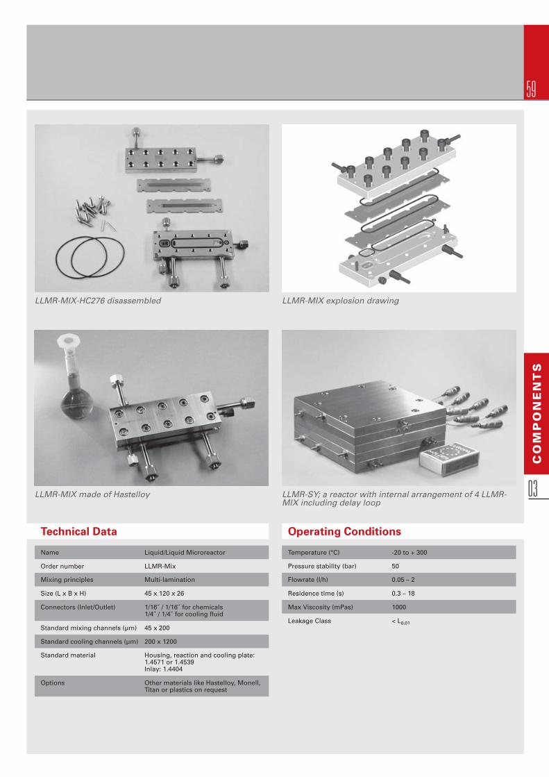
59
LLMR-MIX-HC276 disassembled LLMR-MIX explosion drawing
LLMR-MIX made of Hastelloy LLMR-SY; a reactor with internal arrangement of 4 LLMR-MIX including delay loop
Operating Conditions
Temperature (°C) -20 to + 300 Pressure stability (bar) 50 Flowrate (l/h) 0.05 – 2
Residence time (s) 0.3 – 18 Max Viscosity (mPas) 1000
Leakage Class < L0.01
Technical Data
Name Liquid/Liquid Microreactor Order number LLMR-Mix Mixing principles Multi-lamination Size (L x B x H) 45 x 120 x 26
Connectors (Inlet/Outlet) 1/16˝ / 1/16˝ for chemicals 1/4˝ / 1/4˝ for cooling fl uid
Standard mixing channels (µm) 45 x 200 Standard cooling channels (µm) 200 x 1200 Standard material Housing, reaction and cooling plate: 1.4571 or 1.4539 Inlay: 1.4404 Options Other materials like Hastelloy, Monell, Titan or plastics on request
CO
MP
ON
EN
TS
03

60
Principle
Focusing mixers perform a multi-laminating step and geo-metrically focus the streams (in a way similar to hydro-dynamic focusing) to thin the lamellae and then mix by dif-fusion. Physically speaking, this means having a nozzle feed array, a triangular-type focusing chamber and a thin mixing channel. The SuperFocus Mixer Version 2 (SFIMM-V2) bases upon the simulation, design and characterisation of the former version SFIMM. Development target was to achieve even higher throughputs, to have a robust steel design, e.g. for high-pressure operation and to use a still higher focusing ratio, e.g. to reduce the sensitivity towards blockage. The SuperFocus mixer thus combines both high throughput, which is e.g. characteristic of the StarLam series and uniform fl ow patterns, which is e.g. characteristic for the SIMM components.
Compared to the predecessor design more nozzles enable fl uid feed. The nozzle width was enlarged, thus being lessparticle sensitive, albeit the fi nal focused lamellae width of about 4 µm was kept, i.e. the focusing ratio was increased from 40 formerly to now 178 (and can be set higher on de-mand). To arrange as many as 138 nozzles, a large circular arc was chosen for the feed array. The mixing channel widthand length compares to the former design so that the semi-analytical and experimental reaction type based fi ndings onthe mixing time can be largely transferred to the new design. Although steel is employed as construction material, an op-tional inspection window may allow the monitoring of the fl ow patterns and of the mixing course.
For the SuperFocus SFIMM-V2 throughput of about 350 l/hat a pressure loss of 3.5 bar was determined for watery systems. The formation of fl ow patterns is very uniform,i.e. a multi-lamellae fl ow is found all over the focusing cham-ber until the mixing channel is reached. The known devi-ations from ideal given for any multi-lamellae fl ow are found as well, e.g. that lamellae are thicker at the wall (boundary) than in the interior of the fl ow. In particular this deviation should be less here compared to other systems, as the ratio of outer to inner lamellae is 136:2.
SuperFocus microstructured mixer SFIMM-V2-300 Central plate of the SFIMM-V2-300
The mixing time achievable is 4 ms according to calculationand experiments made with the former design, albeit ex-cluding the time needed for fl owing through the focusing chamber. The latter is dependent on the volume fl ow. Spe-cialty designs with notably reduced focusing time are poss-ible. The same holds for integrated mixing-heating elementconfi gurations, allowing one to perform fast temperature switches for starting and ending reactions in a very short, defi ned time frame, as e.g. done in quench-fl ow analysis.
Disassembled SFIMM-V2-300
SUPERFOCUS INTERDIGITAL MICROMIXERSFIMM-V2
03

61
Multi-lamellae fl ow in the SuperFocus microstructured mixer SFIMM-V2-300
Operating Conditions
Temperature (°C) -40 – 220 Pressure stability (bar) 100 Flowrate (l/h) 10 – 300 Max Viscosity (mPas) 10000 Leakage Class < L0.001
Technical Data
Name SuperFocus Interdigital Micromixer Version 2 -300 Order number SFIMM-V2-300 Mixing principles Multi-lamination Size (L x B x H) 140 x 140 x 40
Connectors (Inlet/Outlet) 1/4˝ / 1/4˝
Standard mixing channels (µm) 500 µm x 5 mm Number of feeding channels 138 Width of feeding channel 260
Focusing ratio 178
Standard material 1.4435 Options Other materials like Hastelloy, Monell or Titan on request; heat exchanger function is possible
CO
MP
ON
EN
TS
03
The SFIMM is meanwhile also pro-duced as smaller device for about one tenth of the original throughput, named SFIMM-V2-30
Mixing structure of SFIMM-V2-30
SFIMM-V2-30 with straight outlet for high viscosity emulsions

62
3 different fl ow patterns:• Y-type jet of IJMM (top)• Fan-shaped jet (middle)• Fanned-out jet (down)
Impinging-Jet Micromixer
Principle
Deliberately slow mixing is an issuewhen fast mixing would have deleter-ious effects on processing, e.g. by plugging the whole system. As a mat-ter of fact, most organic processes areassociated with more or less precipita-tion during the course of reactions. Particle generation is simply not pos-sible in the vast majority of today’s micro devices.
For this reason, a specialty mixer was developed that performs mixing in a ”wall-free” environment, i.e. by two pump-driven, falling jets merging into one in a Y-shaped confi guration. It was shown that the smaller the jet dia-meter, the better the mixing quality. Intense knowledge on jet confi gura-tion as a function of fl ow rate and jet diameter has been documented, in addition to mixing quality judgement.
As a result, the nozzles of the jet mixerhave tiny, only 350 µm wide nozzles. The mixer has been tested for inor-ganic reaction processing such as calcium carbonate precipitation and organic reaction that are associated by strong fouling. The aminolysis of acetyl chloride with n-triethylamine in THF leads to instantaneous heavy precipitation. This reaction hardly can be handled in any other micro device. It is an extreme representative of many other organic reactions that suffer more or less from fouling, e.g. like quaternizations.
IMPINGING-JET MICROMIXERIJMM
03

63
Operating Conditions
Temperature (°C) -40 – 220
Pressure stability (bar) 10 Flowrate (l/h) 0.5 – 3
Residence time (ms) 0
Inner volume (µl) 0 Max Viscosity (mPas) 100 Leakage Class < L0.001
Technical Data
Name Impinging-Jet Micromixer Order number IJMM Mixing principles Jet collision Size (L x B x H) 10 x 35 x 10
Connectors (Inlet/Outlet) 1/8˝ / 1/8˝ Clamp screw
Standard boring-/noozle 350, 500, 1000 diameter d (µm)
Orientation angles (d) 45°, 60°, 90°
Standard material 1.4571 Options Other materials like Hastelloy, Monell or Titan on request
IJMM in a special funnel-like housing for particle production Geometric parameters determine the mixing performance, beside fl ow parameters
CO
MP
ON
EN
TS
03
Impinging-Jet micromixer Plant, IJMP, cf. plant section, including heat exchang-ers, pumps, process control system
IJMM in adequate housing as used for IJMP
Fluid A Fluid B

64
FALLING F ILM MICROREACTORFFMR GROUP
Members of the extended Falling Film Microreactor family
Principle
The Falling Film Microreactor utilizes a multitude of thin fall-ing fi lms that move by gravity force for a typical residence time of seconds up to about one minute. Its unique prop-erties are the good temperature control by an integrated heat exchanger and the specifi c interface of 20,000 m2/m3. Such high mass and heat transfer were e.g. exploited when performing direct fl uorination of toluene with elemental fl uorine in the original version of IMM´s Falling Film Micro-reactor (FFMR-STANDARD). This so far uncontrollable and highly explosive reaction could be managed under safe
03
conditions and with control over the reaction mechanism and therewith selectivity.
Due to the high raised interest for such a kind of device, starting from the FFMR-STANDARD in recent years the con-cept has faced several extensions and even more important has been brought from lab scale to pilot and production scale. The several types of Falling Film Microreactors including the new ones are introduced in the following.

65
Reactor assembled Reactor disassembled Reaction plates
CO
MP
ON
EN
TS
03
Thermographic monitoring: Initial wetting fl ow (FFMR-STANDARD)Falling fi lm principle in a multi-channel architecture
Research Topics at IMM
IMM is exploring the potential of further structuring the straight reaction channels in the Falling Film Microreactor. So IMM realised recently a reaction plate in which each of the channels have been modifi ed by incorporation of addi-tional grooves in order to improve via recirculation fl ows the liquid side mass transport. First tests based on CO2 absorption in aqueous sodium hydroxide have proven that signifi cant performance improvements can be achieved.
FFMR Standard
Technical Data
Name Falling Film Microreactor (Standard) Order number FFMR-STANDARD Size (L x B x H) 120 x 76 x 40
Connectors (Inlet/Outlet) all 1/4˝
Material 1.4571 for housing and reaction plate Copper for cooling plate Borofl oat glass for inspection
Standard reaction channels 300 x 100 (64 channels) (µm) 600 x 200 (32 channels) 1200 x 400 (16 channels) Reaction channel length (cm) 7.6
Gas chamber height (mm) 5
volume of gas chamber (mm3) 13336
Standard cooling channels Width: 1.5 (mm) Depth: 0.5
Options Other materials like Hastelloy, Monell or Titan on request
Operating Conditions
Temperature (°C) 180 (option: 300) Pressure stability (bar) 10 (without Borofl oat glass: 20) Flowrate (l/h) 0.05 for channel geometry 300 µm 0.6 for channel geometry 600 µm 1.5 for channel geometry 1200 µm
Residence time (s) 0.8 – 20
Liquid fi lm thickness (µm) 25 – 100 Interfacial area (m2/m3) up to 20000
Leakage Class L0.01

66
FFMR-CYLINDRICAL
FFMR-STANDARD and -LARGEReaction plates for FFMR-STANDARD and -LARGE
FFMR-LARGE & FFMR-CYLINDRICAL
03
FFMR GROUP
Starting from FFMR-STANDARD two new reactor types have been developed targeting at a tenfold increase of the structured surface area on the reaction plate. In the FFMR-LARGE therefore the length and the number of channels have been increased by a factor of 100.5. From the general design FFMR-LARGE is quite similar to FFMR-STANDARD. FFMR-CYLINDRICAL follows another approach. The reaction channels are now engraved on the outside of a metallic tube. The cylindrical shape allows a quite compact design in this case. The number of the reaction channels has been increased by a factor of 7.5, the length of the channels has been elongated a bit to get a tenfold increase of structured surface area. The FFMR-CYLINDRICAL is of special interest for photochemistry applications.
Operating Conditions
Temperature (°C) 180 180
Pressure stability (bar) 10 (without glass: 20) 5
Flowrate (l/h) investigated range 0.24 - 1.20 investigated range 0.24 - 1.20
Residence time (s) calculated 23 - 8 calculated 16 - 6
Liquid fi lm thickness (µm) calculated 60 - 100 calculated 45 - 76
Interfacial area (m2/m3) about 9814 - 16780 about 13140 - 22470
Technical Data
Name Falling Film Microreactor Large Falling Film Microreactor Cylindrical
Order number FFMR-LARGE FFMR-CYLINDRICAL
Size (L x B x H) 320 x 156 x 40 80 x 130
Connectors all 1/4´´ 1/8´´ and 1/4´´ (welded tubes)
Material 1.4571 for housing and reaction/cooling plate 1.4571 Quartz glass for inspection DURAN® glass for inspection
Standard reaction channels (µm) 1200 x 400 (50 channels) 1200 x 400 (120 channels)
Reaction channel length (cm) about 25 about 10
Gas chamber height (mm) 4,5 5
Volume of gas chamber (mm3) 90000 100000
Standard cooling channels (mm) Width: 0.2 Width: 1.2 Depth: 0.4 Depth: 1.0
Options Other materials on request Other materials on request
66

67
STACK-1x-FFMR-LAB STACK-10x-FFMR-LARGE
CO
MP
ON
EN
TS
03
STACK-1x-FFMR-LARGE (open/closed)
Brazed Falling Film Microreactors (STACK-FFMR)
The reactor concept of FFMR-STANDARD and -LARGE has been transferred to a pure plate design to which brazing as joining technology can be applied. The STACK-1x-FFMR-LARGE thereby represents the equivalent to FFMR-LARGE and the basic functional element for following numbering-up. So STACK-10x-FFMR-LARGE contains 10 functional elements. To round up the brazed reactor program also a new lab version has been developed (STACK-1x-FFMR-LAB). Compared to STACK-10x-FFMR-LARGE it should allow identical experimentation at a throughput of only 1/100 of the STACK-10x-FFMR-LARGE. Brazing technology opens the door for specifi cally adopted reactors for high pressure applications.
Outlook for even larger reactors: test reaction plate for FFMR-XXL
Technical Data
Name / Order number STACK-1x-FFMR-LAB STACK-1x-FFMR-LARGE STACK-10x-FFMR-LARGE
Size (L x B x H) 294 x 28 x 19 296 x 118 x 12 296 x 118 x 75
Connectors all 1/8´´ all 3/8´´ all 3/8´´
Material 1.4571 + Ni screen printing braze 1.4571 + Ni screen printing braze 1.4571 + Ni screen printing braze
Standard reaction channels (µm) 1200 x 400 (50 channels) 1200 x 400 (50 channels) 1200 x 400 (50 channels)
Reaction channel length (cm) about 25 about 25 about 25
Reaction channels number 5 50 500 Gas chamber height (mm) 4 4 4
Volume of gas chamber (mm3) 7300 73000 730000
Standard cooling channels (mm) Width: 1.2 Width: 1.2 Width: 1.2 Depth: 0.4 Depth: 0.4 Depth: 0.4
Options On request On request On request
Operating Conditions
Temperature (°C) 180 up to 800 @ 1 bar up to 800 @ 1 bar
Pressure stability (bar) 10 up to 50 @ 25 °C up to 50 @ 25 °C
Flowrate (l/h) about 0.02 - 0.12 about 0.24 - 1.20 about 2.4 - 12.0
Residence time (s) about 23 - 8 about 23 - 8 about 23 - 8
Liquid fi lm thickness (µm) about 60 - 100 about 60 - 100 about 60 - 100
Interfacial area (m2/m3) about 9814 - 16780 about 9814 - 16780 about 9814 - 16780

68
GAS PHASE MICROREACTORGPMR
Gas Phase Microreactor
Principle
The Gas Phase Microreactor com-prises a stack of several microstruc-tured plates (generally 10 + 10 plates) that are arranged for counter-fl ow or co-current fl ow practice. Each plate consists of 34 parallel micro channels of 300 µm width and 200 µm depth. The plate stack is encompassed by twoceramic Macor® plates, for thermal in-sulation to the environment and the two steel end caps. The GPMR is a modular system which can also be customized (e.g. one passage solely with electrical heating: No insulation plates, special designed end caps with integrated heat cartridges).
The plates can be coated with catalyst, so that the assembled device can beoperated as gas-phase reactor, eitherwith or without internal heat transfer.
Intense studies on periodic reactions were made with this reactor by threewell-known European research groups,concerning the oxidation of propane, the dehydration of isopropanol, and the selective oxidation of isoprene to citraconic anhydride.
On request, catalyst deposition in themicro channels can be offered as well.Most commonly, wash coating of dif-ferent carriers, e.g. of various alumi-nas, and subsequent catalyst impreg-nation are applied. Coprecipitation and sol-gel techniques were applied as well for catalyst deposition.
The device can also be used as a gas-phase and/or liquid-phase micro heat exchanger.
Counter-fl ow principle
03

69
Plate coated with catalystGas phase reactor installed in bench-scale plant
Operating Conditions
Temperature (°C) 500 Pressure stability (bar) 3 Flowrate (l/h) liquid/gas 1 – 7 / 1 – 600
Leakage Class L0.1
Heat transfer area (m2/m3) 18000 Total inner surface per layer (mm2) 580 Specifi c inner surface per layer (m2/m3) 2900 Active inner volume per layer (mm3) 32 Operation mode Counter- or co-current fl ow
Technical Data
Name Gas Phase Microreactor Order number GPMR Size (L x B x H) 70 x 70 x 55
Connectors (Inlet/Outlet) 1/8˝
Standard material 1.4571 for housing and catalyst carrier Glass ceramics MACOR for insulation layer
Number of catalayst plates 20 Size of catalyst plate (mm) 40 x 40 Channel geometry of the catalyst plates (µm) 300 x 200 Options GPMR is also usable as a single heat exchanger; end caps for heating cartridges
CO
MP
ON
EN
TS
03GPMR integrated into a plant, here as simple heat exchanger (COMH) for education purpose
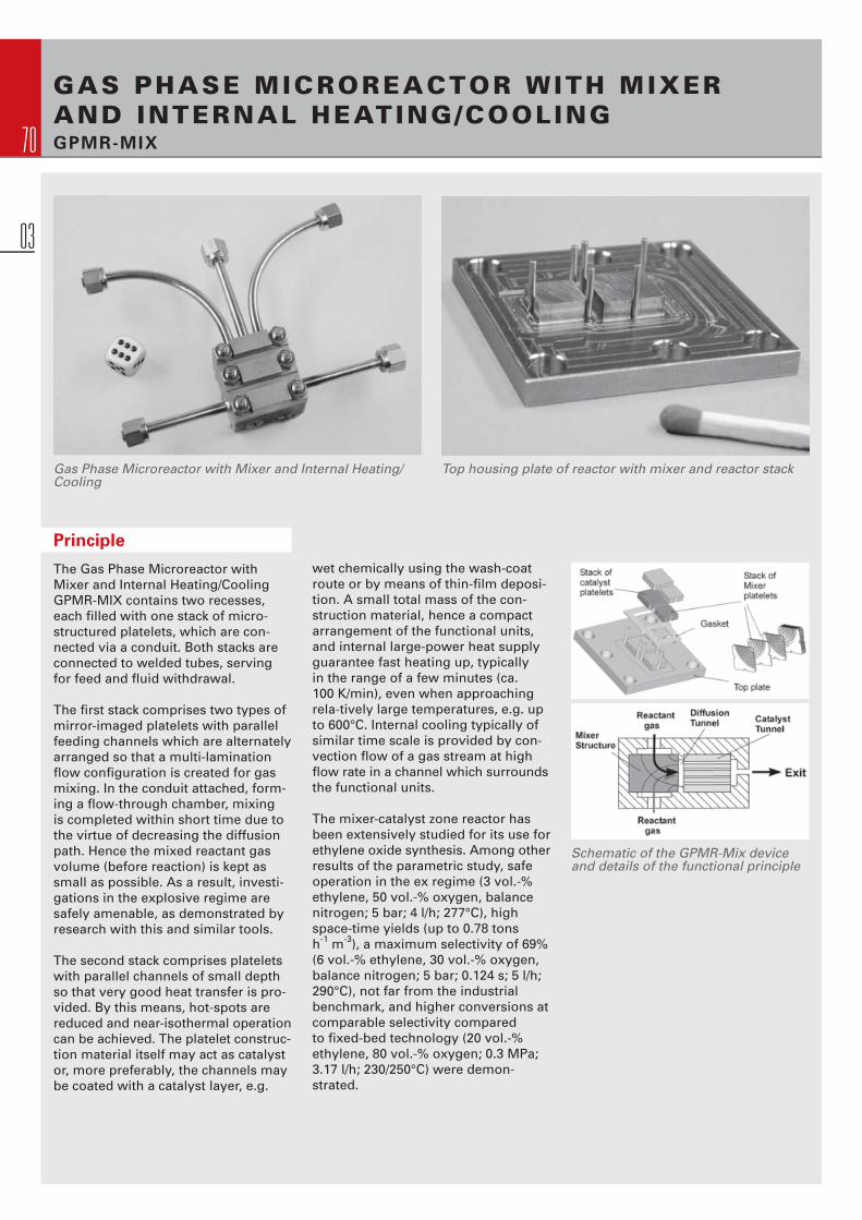
70
GAS PHASE MICROREACTOR WITH MIXER AND INTERNAL HEATING/COOLING GPMR-MIX
Gas Phase Microreactor with Mixer and Internal Heating/Cooling
Top housing plate of reactor with mixer and reactor stack
Schematic of the GPMR-Mix device and details of the functional principle
Principle
The Gas Phase Microreactor with Mixer and Internal Heating/Cooling GPMR-MIX contains two recesses, each fi lled with one stack of micro- structured platelets, which are con-nected via a conduit. Both stacks are connected to welded tubes, serving for feed and fl uid withdrawal.
The fi rst stack comprises two types of mirror-imaged platelets with parallel feeding channels which are alternately arranged so that a multi-lamination fl ow confi guration is created for gas mixing. In the conduit attached, form-ing a fl ow-through chamber, mixing is completed within short time due to the virtue of decreasing the diffusion path. Hence the mixed reactant gas volume (before reaction) is kept assmall as possible. As a result, investi-gations in the explosive regime are safely amenable, as demonstrated by research with this and similar tools.
The second stack comprises plateletswith parallel channels of small depth so that very good heat transfer is pro-vided. By this means, hot-spots arereduced and near-isothermal operationcan be achieved. The platelet construc-tion material itself may act as catalyst or, more preferably, the channels maybe coated with a catalyst layer, e.g.
wet chemically using the wash-coatroute or by means of thin-fi lm deposi-tion. A small total mass of the con-struction material, hence a compact arrangement of the functional units, and internal large-power heat supply guarantee fast heating up, typically in the range of a few minutes (ca. 100 K/min), even when approaching rela-tively large temperatures, e.g. up to 600°C. Internal cooling typically of similar time scale is provided by con-vection fl ow of a gas stream at highfl ow rate in a channel which surroundsthe functional units.
The mixer-catalyst zone reactor has been extensively studied for its use forethylene oxide synthesis. Among otherresults of the parametric study, safe operation in the ex regime (3 vol.-% ethylene, 50 vol.-% oxygen, balancenitrogen; 5 bar; 4 l/h; 277°C), high space-time yields (up to 0.78 tons h-1 m-3), a maximum selectivity of 69%(6 vol.-% ethylene, 30 vol.-% oxygen, balance nitrogen; 5 bar; 0.124 s; 5 l/h; 290°C), not far from the industrial benchmark, and higher conversions at comparable selectivity compared to fi xed-bed technology (20 vol.-% ethylene, 80 vol.-% oxygen; 0.3 MPa; 3.17 l/h; 230/250°C) were demon-strated.
03

71
Individual parts of GMPR-Mix Mixer and reaction platelet Laser-cut mixer platelets
Operating Conditions
Temperature (°C) 600 Pressure stability (bar) 50 Flowrate (l/h) 5
Residence time (s) 0.025 – 2
Leakage Class < L0.1 Specifi c surface area (m2/m3) 12700 Total inner surface per reaction layer (mm2) 54 Specifi c inner surface per reaction layer (m2/m3) 3840 Active inner volume per layer (mm3) 2.5
Technical Data
Name Gas Phase Microreactor with Mixer and Internal Heating Order number GPMR-MIX Size (L x B x H) 40 x 40 x 30
Connectors (Inlet/Outlet) 1/4˝
Standard material Inconell 600 (2.4816) for housing and top plate 1.4571 for mixing and catalyst plates
Number of mixing plates 10
Size of mixing plates (mm) 7.5 x 7.5
Channel geometry of mixing plates (µm) 180 – 490 x ~ 100 Number of catalayst plates 10
Size of catalyst plate (mm) 9.5 x 9.5 Channel geometry of the catalyst plates (µm) 460 x 125
CO
MP
ON
EN
TS
03

72
CATALYST MICRO BURNER REACTORCMBR
Principle
The Catalyst Micro Burner Reactor is atesting reactor composed of a housing which can take in a stack of up to 16 microstructured plates. The plates are easily exchangeable and the assembly of the reactor is simple.
On demand, the reactor plates can be coated with various carrier/catalystsystems. The CMBR was designed for testing the catalysed burning of fuels
Catalyst Micro Burner Reactor
with different catalysts, however, it may be as well applied as a testing re-actor for all kind of heterogeneous gas phase reactions at fl ow-rates exceed-ing the range of small-scale laboratory devices.
Heating of the reactor is realised by heating cartridges with temperature determination feasible at two positionsinside the reactor.
03
The Catalyst Micro Burner Reactor isdesigned for a power generation in therange of several hundreds of Watts byburning various fuels. Full conversionof 32 g/h methanol was achieved witha conventional Pt-catalyst at 130°C re-action temperature. No other productsthan carbon dioxide and water were found above the detection limit. Thus absence of bypass effects could be proven.

73
Single parts of the Catalyst Micro Burner Reactor
Operating Conditions
Temperature (°C) 550 Pressure stability (bar) 5 Flowrate (l/h) 10 – 150
Residence time (ms) 0.10 – 1
Leakage Class < L0.1
CO
MP
ON
EN
TS
03Technical Data
Name Catalyst Micro Burner Reactor Order number CMBR Size (L x B x H) 160 x 120 x 50 Connectors (Inlet/Outlet) 1/4˝
Standard material 1.4571
Number of catalayst plates 1 – 16 Size of catalyst plate (mm) 50 x 50 Channel geometry of the catalyst plates (µm) 600 x 400
Micro channel surface area per platelet (mm2) 588
Options Other materials on request

74
Catalyst Testing Microreactor with end caps for parallel operation
Stack of cartridges with coated micro-structured plates
Two end caps for parallel operation
Principle
The Catalyst Testing Microreactor con-sists of a housing comprising twentymicro structured plates positioned pair-wise face to face resulting in ten levelsof parallel microchannels. On demand,the micro structured plates can be coated with various carrier/catalystsystems. They are easily exchangeableusing an included mounting tool and relatively inexpensive due to mass fabrication by wet-chemical etching. By simple exchange of the end caps a decision can be made whether to operate the microreactor in serial or in parallel mode.
Parallel operation (1 in, 10 out):
Using a diffuser-type end cap, the microstructured plates are fed simul-taneously by the one common inlet stream. The sub-streams leave then through the ten separate outlets that can be analyzed accordingly.
10 levels with different catalysts but same feed gas.
Screening of catalysts.
Parallel operation (10 in, 10 out):
Even testing ten different catalysts us-ing ten different gases (at similar pres-sure) can be applied by assembling thereactor with two end caps for parallel operation.
10 levels with different catalysts and/ or different gases.
Screening or numbering-up of cata-lysts.
Serial operation (1 in, 1 out):
Using two other end caps similar in shape, the one inlet stream fl ows seri-ally in a zigzag manner from one plate to the other, being turned around and guided to the next level and so on, fi nally resulting in a path of ten times length compared to the single plate length, respectively ten times the resi-dence time.
Up to 10 plates with identical catalyst may be installed.
Variation of the reactor length.
CATALYST TESTING MICROREACTORCTMR
03

75
Special version for 800°C and 20 bar operation
Standard version disassembled Alternative heating option with one heat jacket instead of 10 heat cartridges
Technical Data
Name Catalyst Testing Microreactor Order number CTMR Size (L x B x H) 100 x 100 x 108
Connectors (Inlet/Outlet) 1/4˝ / 1/16˝ for parallel operation 1/8˝ / 1/8˝ for serial operation
Standard material 1.4841 for housing 1.4742 for catalyst plates
Number of catalayst plates 20 Size of catalyst plate (mm) 50 x 14 Options Other materials on request
Operating Conditions
Temperature (°C) 800 Pressure stability (bar) 20 (100 bar at 400°C) Standard fl ow velocity (m/s) 0.4 – 40
Residence time (ms) 0.025 – 2000
Leakage Class < L0.1
Options
Catalyst plates can be delivered with various channel geometries:
Channel geometry (width µm x depth µm): 2900 x 300 Number of channels: 3 2000 x 300 4
1000 x 300 7
1000 x 100 7
750 x 300 9
750 x 100 9
500 x 300 12
500 x 100 12
CO
MP
ON
EN
TS
03

76
LASER-WELDED MICRO HEAT EXCHANGERWT-SERIES
Principle
The WT-series was developed as a heat exchanger for liquid/liquid, gas/liquid or gas/gas applications and canalso serve for evaporation or conden-sation. They comprise a laser welded stack of arranged microstructured plates enabling a counter- or co-currentfl ow scheme. Being assembled withconventional 1/4” or 3/8” tubes, easy integration into the existing tubing sys-tem of pilot- or small-scale productionplants is possible.
Laser-welded micro heat exchanger group class (WT-series), WT-404, WT-304, WT-204 (from left to right)
The core elements are chemically etched microstructured plates, sealed by high-precision laser welding. These heat exchangers are normally designed for fl ow rates between 1 l/h up to 400 l/h; higher fl ow rates of up to 1000 l/h are possible at moderate pressure drops. The high effi ciency and heat transfer coeffi cients of the micro channels are even more enhanced compared to conventional heat exchangers due to the low material thickness (low heat resistance) and high inner specifi c surface.
Additionally, the channels of plates can be coated with catalyst using the heat exchanger as reactor for heterogeneously catalysed reactions, typically gas-phase reactions, like e.g. steam reforming.
Single plates of the WT…08-series
Single plates of the WT…04-series
03

77
Special type HxA Special Heat Exchanger, also for condensing
HCOMH
Technical Data
Name Laser-Welded Micro Heat Exchanger Series Order number WT 204 WT 304 WT 404 Size (L x B x H) 60 x 24 x 23 80 x 34 x 32 100 x 44 x 42
Connectors (Inlet/Outlet) 1/4˝ / 1/4˝ 3/8˝ / 3/8˝ 3/8˝ / 3/8˝
Material 316 Ti, others on request Dimensions of heating channels (µm) 800 x 400, others on request
Operating Conditions
Temperature (°C) up to 1000 @ 1 bar Pressure stability (bar) 5 @ 25 °C (higher upon request, max. 20 bar) Flowrate (water, l/h) 0.5 – 50 2.5 – 250 6 – 600
CO
MP
ON
EN
TS
03
Other examples of laser-welded micro heat exchangers

78
BRAZED MICRO HEAT EXCHANGERS HX-SERIES
Principle
This novel HX-series was developed as a heat exchanger for liquid/liquid, gas/liquid or gas/gas applications at high pressure and temperature regimes. They comprise a brazed stack of aligned plates enabling a counter- or co-current fl ow scheme. The core elements are chemically etched microstructured plates, laminary joined applying brazing technology. These new heat exchangers are normally designed for fl ow rates between 1 l/h up to 400 l/h; higher fl ow rates of up to 1000 l/h are possible at moderate pressure drops. The high effi ciency and heat transfer coeffi cients of the micro channels are even more enhanced compared to conventional heat exchangers due to the low material thickness (low heat resistance) and high inner specifi c surface.
Brazed micro heat exchanger group class (HX-series); HX-204, HX-304 (top right), HX-404 (bottom right)
03
Single plates of the HX-304-series (left: blank, right: coated with screen printing paste)

79
CO
MP
ON
EN
TS
03
Complex feed structures are feasible: The picture shows the feeding struc-ture for a SuperFocus like micromixer with nozzle like outlets for an inner liquid phase surrounded from top and bottom from chains of rectangular feed structures for the outer liquid phase.
Section view of two brazed plates aligned face to face
High Pressure Microreactor with two temperature zones (Type HPMR-2TZ-V2-90ml))
At IMM the microstructured reactor plates are coated with the brazing paste by using the screen printing machine Type THIEME 1010 E.
Technical Data
Name Brazed Micro Heat Exchanger Series Order number HX 204 HX 304 HX 404 Size (L x B x H) ca. 100 x 60 x 20 ca. 150 x 80 x 25 ca. 200 x 120 x 40
Connectors (Inlet/Outlet) 1/4˝ / 1/4˝ 3/8˝ / 3/8˝ 1/2´´ / 1/2´´
Material 316 Ti, others on request Dimensions of heating channels (µm) 1000 x 600, others on request
Operating Conditions
Temperature (°C) up to 800 @ 1 bar Pressure stability (bar) up to 500 @ 25 °C Flowrate (water, l/h) 0.5 – 50 2.5 – 250 10 – 1000
Research Topics at IMM
Brazing opens the possibility of inter-connecting large-area reactor struc-tures monolithically. Thereby large interior volumes are possible with high pressure strength at the same time. Further the brazing technique makes a multiplicity of new reactor geometries accessible. IMM extended strongly the application of the brazing technique as sealing technology for microreactors of different functionality. Besides the HX-series the technology has e.g. also been applied for realising the proto-type of a high pressure microreactor with two temperature zones with a reactor interior volume on the reaction side of 90 ml (HPMR-2TZ-V2-90ml), which is tested for operation at 120 bar @ 250 °C.
Brazed (high pressure) Microreactors

80
Tube Heat Transfer Micro Device
Principle
The Tubular Heat Transfer Micro Deviceis a microstructured heat exchanger, designed for electrical heating of gas-es and liquids. The optimized size ofthis device allows a very fast heatingup as well as fast changes of tempera-tures. Being offered in two sizes, themaximum power rate to be transferredcan be up to 800 W with a thermal effi -ciency > 90% (depending on operationconditions).
Several options can be offered:• THTMD solely• THTMD plus suitable heat cartridge (if suitable electronic control unit is at hand)• Full package, comprising THTMD plus heat cartridge, two thermo- couples and electronic control unit
THTMD in parts before laser-welding
Technical detail of heat exchanger structure
In the latter case, the temperature ofthe heating process is basically con-trolled by a thermocouple in the THTMD-outlet as well as an additional thermocouple to avoid overheating is integrated within the heating cartridge itself.
Operation conditions are tested for maximum 300°C @ 1 bar or 45 bar @ 25°C.
TUBE HEAT TRANSFER MICRO DEVICETHTMD
03
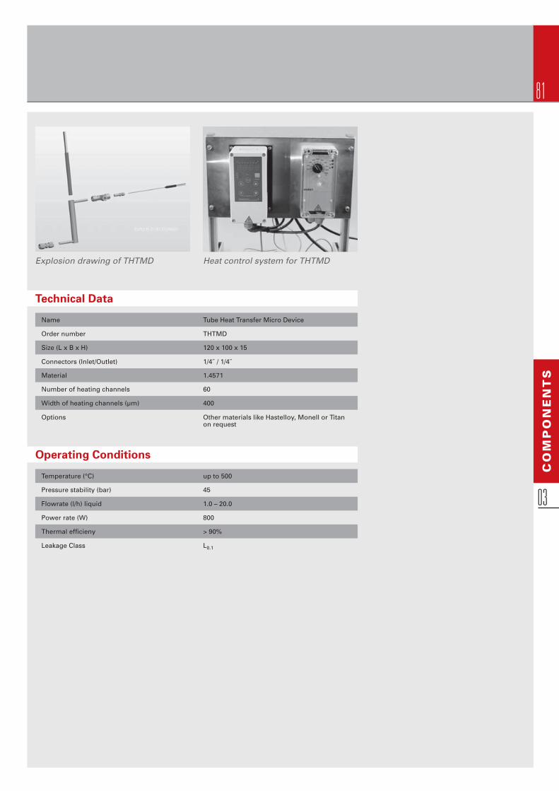
81
Explosion drawing of THTMD Heat control system for THTMD
Operating Conditions
Temperature (°C) up to 500 Pressure stability (bar) 45 Flowrate (l/h) liquid 1.0 – 20.0
Power rate (W) 800
Thermal effi cieny > 90%
Leakage Class L0.1
Technical Data
Name Tube Heat Transfer Micro Device Order number THTMD Size (L x B x H) 120 x 100 x 15
Connectors (Inlet/Outlet) 1/4˝ / 1/4˝
Material 1.4571
Number of heating channels 60 Width of heating channels (µm) 400 Options Other materials like Hastelloy, Monell or Titan on request
CO
MP
ON
EN
TS
03
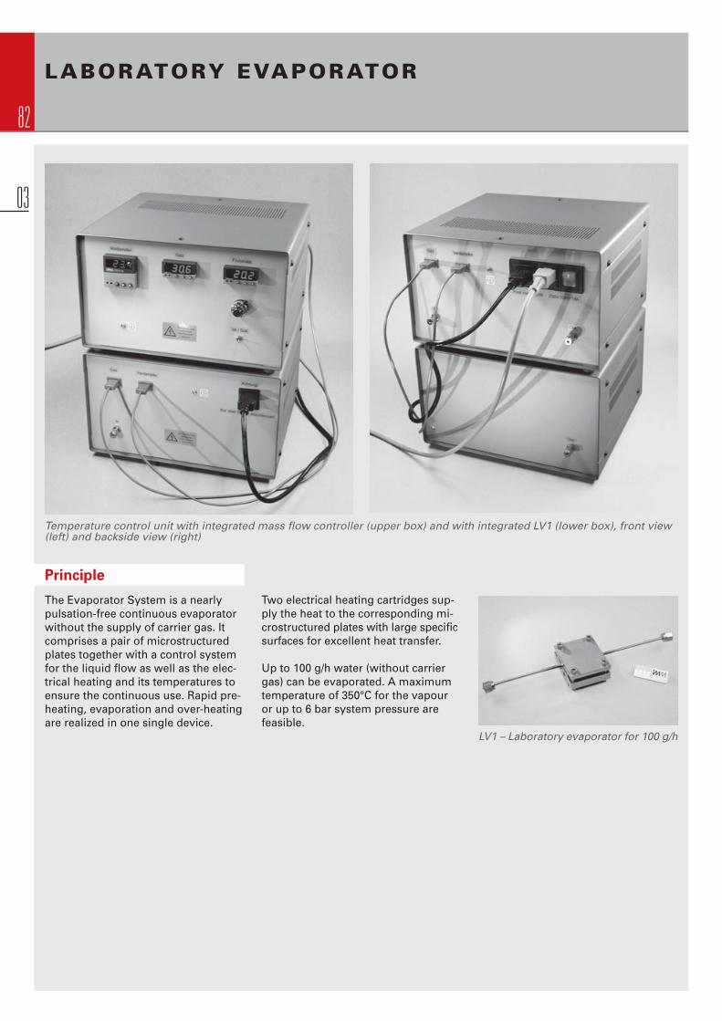
82
LABORATORY EVAPORATOR
Temperature control unit with integrated mass fl ow controller (upper box) and with integrated LV1 (lower box), front view (left) and backside view (right)
Principle
The Evaporator System is a nearly pulsation-free continuous evaporator without the supply of carrier gas. It comprises a pair of microstructured plates together with a control system for the liquid fl ow as well as the elec-trical heating and its temperatures to ensure the continuous use. Rapid pre-heating, evaporation and over-heatingare realized in one single device.
Two electrical heating cartridges sup-ply the heat to the corresponding mi-crostructured plates with large specifi c surfaces for excellent heat transfer.
Up to 100 g/h water (without carrier gas) can be evaporated. A maximum temperature of 350°C for the vapour or up to 6 bar system pressure are feasible.
LV1 – Laboratory evaporator for 100 g/h
03

83
LV1 – with open heating housing LV1 – disassembled
Operating Conditions
Temperature (°C) 400 Pressure stability (bar) 6 Temperature (°C) of Vapor up to 350
Flowrate (g/h) 10.0 – 100.0
Power rate (W) 400
Technical Data
Name Evaporator System Order number LV1 Size (L x B x H) 300 x 300 x 360
Connectors (Inlet/Outlet) 1/8˝ / 1/8˝
Material 1.4301
CO
MP
ON
EN
TS
03

84
GENERAL TERMS AND CONDITIONS OF DELIVERY AND SALE
1. General Provisions
1.1 The terms and conditions set forth herein apply to deliveries and sales to entrepreneurs, public legal persons and public special funds accord-ing to § 310 section 1 BGB (German Civil Code) (“Purchaser”) exclusively.
1.2 These terms and conditions apply to all our agreements and quotations,even to prospective agreements and quotations, and apply exclusively.
1.3 Purchaser’s conditions which are contradictory to or diverging from our terms and conditions do not apply unless their validity is expressly agreed in written form.
1.4 These terms and conditions also apply in case we supply even though con-tradiction or divergence of Purchaser’s conditions from our terms and con-ditions is known to us.
1.5 All agreements between us and Purchaser for the purpose of performance of the contract at hand require written form. This also applies to the waiver of the written form itself.
2. Offers and Prices
2.1 Our offers are not binding until our written order confi rmation is submitted. Oral offers are not valid unless a written confi rmation is submitted.
2.2 Our prices are effective “ex factory” plus value added tax and costs of delivery and packaging.
2.3 Unless a fi xed price agreement is reached, we reserve the right to adequatelyadjust the price due to changed costs for wages, material and distribution of deliveries, which are carried out three months after conclusion of the contract or later on.
3. Extent of Delivery and Performance
3.1 The order confi rmation discloses the whole extent of the delivery and per-formance owed.
3.2 Purchaser bears the costs and risks of delivery.
3.3 In case we owe a separable performance, partial delivery is permitted for relevant reasons to a reasonable extent. We are entitled to invoice partial delivery separately.
3.4 Specifi cations as to time of delivery are not binding unless a binding time of delivery is expressly agreed. If we do not meet a binding time of delivery, Purchaser will be entitled to withdraw from the contract, if we do not de-liver within an adequate additional respite granted by Purchaser.
Upon our request Purchaser is obliged to declare within an adequate respite, whether he withdraws from the contract because of the delay of the deliveryor demands delivery.
3.5 If the Parties agree that our performance will not be initiated until down payment or advance payment has been made, delivery time will not begin unless the according amount has been credited to our business account subject to a separate agreement.
3.6 If we exceed time of delivery, Purchaser – in case Purchaser credibly shows, that resulting from this he suffered damage – will be entitled to demand indemnifi cation amounting to 0.5 % of the delivery value for each completedweek of delay, but not exceeding a total of 5 % of the delivery value.
3.7 Damages claims of Purchaser resulting from delay of delivery as well as damages claims in place of delivery exceeding the limits set by foregoing no. 6 are excluded in all cases of delayed delivery, even after expiry of an additional respite of delivery. This shall not affect the cases where IMM’s liability is mandatory by law in cases of intent, gross negligence or damage to life, body or health.
The foregoing regulation does not stipulate a reversal of the burden of proof for Purchaser.
3.8 Meeting respites of delivery requires timely receipt of all documents as well as required permissions and clearances and particularly of plans to be de-livered by Purchaser, as well as compliance with agreed conditions of pay-ment and other obligations by Purchaser. If these requirement are not timely fulfi lled, respite of delivery will be adequately prolonged, unless we areresponsible for the delay.
3.9 Delivery time will be extended adequately in case of force majeure, strike, lockout, breakdown, delay of external suppliers and other unexpected circum-stances. In such cases we reserve the right to withdraw from the contract taking into account Purchaser’s interests.
3.10 If Purchaser defaults in payment in the context of other present contractual relationships between Purchaser and us, we are entitled to detain delivery under this contract for the duration of default of payment, prior notice to Pur- chaser provided. This shall not apply in case of minor outstanding payment.
3.11 In case of application to open insolvency proceedings as well as of affi da-vit of means according to § 807 ZPO (German Code of Civil Procedure) we are entitled to detain delivery until consideration has been executed or until Purchaser furnishes appropriate security. Furthermore, we are en-titled to claim full payment and – after futile expiration of a reasonable additional respite – to withdraw from the contract unless Purchaser fur-nishes adequate security on our demand.
4. Payment Terms
4.1 Invoices are payable net within 30 days as of invoice date.
4.2 Unless otherwise agreed, ordering amounts of more than 10.000,-- EUROwill be invoiced in two rates of 50% of the order value each. If so and unlessotherwise agreed, delivery will not be performed until receipt of the fi rst rate. The second rate is due after delivery.
4.3 Bills of exchange and cheques are only accepted on explicit agreement and only on account of performance and they shall not be deemed to constitute payment until honoured. In the event of such agreed submission of bills of exchange or cheques, payment shall only be deemed to have been made upon encashment, due payment provided.
4.4 On default of payment Purchaser has to pay interest at 8 percentagepoints above the current base rate according to § 247 BGB (German Civil Code). We reserve the right to claim a higher damage as a result of de-fault.
4.5 Purchaser will be entitled to set off with counterclaims only, if said claims are undisputed or legally confi rmed.
Purchaser is entitled to lay a lien on his payment only as far as the counter-claim is based on the same contractual relationship.
In case of reasonable partial delivery Purchaser is not entitled to lay a lien on his payment for reasons of outstanding parts of delivery.
5. Retention of Title
5.1 We reserve the right of property in the delivery items until Purchaser com-pletely satisfi es our claims arising from the contract at hand.
5.2 As long as property is not transferred to Purchaser, Purchaser is obliged to
treat the delivery item with care. Particularly Purchaser is obliged to insurethe delivery item suffi ciently according to its replacement value and at Purchaser‘s own expenses against damage caused by theft, fi re and water.Claims arising from said insurances as well as everything possibly acquiredas a substitute according to § 285 BGB (German Civil Code) are herewith assigned from Purchaser to us; we hereby accept assignment. Notwith-standing the assignment, Purchaser is authorised to assert and collect claims in his own name, by legal proceeding if necessary. Our entitlementto collection of debts remains unaffected by Purchaser‘s authorisation. Necessary maintenance or inspections are to be performed by Purchaser at Purchaser‘s own expenses in due time.
04

85
AN
NE
X
04
5.3 In case of breach of contract, particularly of default of payment or breach of these terms and conditions, we reserve the right to withdraw from the con-tract at hand and to reclaim property.
5.4 In case of garnishment, requisition or other disposals or interventions of third parties, Purchaser is obliged to notify us forthwith. Purchaser shall be liable for our detriment, if and to the extent to which third parties are not able to refund costs arising in or out of court for actions taken in accord-ance with § 771 ZPO (German Code of Civil Procedure).
5.5 Purchaser is entitled to resale delivery items under reserved property in regular course of business. Purchaser herewith assigns to us all claims against Purchaser‘s customers arising from said resale at the fi nal amount of the invoice (incl. value added taxes). This assignment is valid irrespect-ive of whether the delivery items under reserved property were resold with-out or after product processing. Even after cession Purchaser remainsauthorised to collect outstanding claims. This shall not infl uence our right to collect the debt. However, we will not collect the debt as long as Purchaser fulfi ls his obligation of payment, Purchaser is not in default of payment, no application for opening insolvency proceedings is fi led and payment has not been stopped.
5.6 If the delivery items under reserved property are worked, processed or modifi ed by Purchaser, such working, processing and modifi cation shall always be deemed to be performed on our behalf. In this case the remain-der of Purchaser in the delivery item is continued in the worked, processed or modifi ed item. Shall the delivery item under reserved property be pro-cessed or modifi ed together with other objects not belonging to us, we acquire co-ownership in the resulting merchandise at an interest depend-ing on the ratio of delivery items‘ objective value to the other objects‘ value which do not belong to us. Relevant value will be that at the time of work-ing, processing or modifi cation. The same shall apply in case of commingl-ing, mixture or combination. Should the resulting merchandise consist of Purchaser‘s objects forming the main part, Purchaser herewith under-takes to assign proportionate co-ownership to us according to our con-tribution and keeps the ownership or co-ownership by us in safe custody. For securing our claims against the Purchaser Purchaser herewith assigns to us all claims, which accrue to him from connection of the delivery items under reserved property with immovable property; we hereby accept assign-ment.
5.7 We hereby covenant to gradually release at Purchaser‘s demand thesecurities obtained by retention of title in so far as the property’s value exceeds the debts to be secured by more than 20 %.
6. Transfer of Risk
6.1 If the delivery items are sent to Purchaser at Purchaser’s demand, Purchaserbears the risk of accidental destruction or deterioration of the delivery items from the time of dispatch and at the latest from the time the delivery items leave the works/storage. This applies irrespective of whether dispatchis initiated from place of performance and irrespective of who bears the costs of delivery.
6.2 If dispatch, service, execution of setting up or assembly, taking over for operation, or trial operation are delayed for reasons attributable to Pur-chaser or Purchaser is in default of acceptance for other reasons, risk will be transferred to Purchaser.
7. Liability for Faulty Goods
7.1 Period of warranty shall expire twelve (12) months after time of delivery.
7.2 Claims because of fault are excluded in case of negligible deviation, devia-tion being customary in trade and technically unavoidable deviation from the agreed condition, in case of negligible impairment of serviceability, in case of fair wear and tear and damages, which accrue after transfer of risk because of careless or faulty treatment, immoderate stress, use of unapt equipment or because of special exterior infl uences, which are not subject to the contract at hand. Claims because of fault are excluded in case of corrosion damage unless Purchaser pointed out the intended use
of the delivery items in connection with special chemicals. If Purchaser or third parties carry out inappropriate maintenance or changes, no claims because of fault emerging from such inappropriate maintenance or changeswill accrue.
7.3 We do not accept liability for our product being apt for a special intention. All information, irrespective of being oral or written, relating to possible fi elds of application of our products, is served to the best of our knowledge. It is based on our experience and therefore is not guaranteed. Purchaser is responsible to inspect the suitability of our products for the intended fi elds of application.
7.4 We do not warrant freedom from third parties‘ rights in the delivery items.
7.5 Purchaser will examine the consignment immediately after receipt for dam-ages. If any defect becomes apparent during such inspection or is later de-tected, Purchaser has to give written notice thereof including description of the fault to us immediately, but not later than fi ve (5) working days after delivery and discovery respectively.
7.6 If despite all applied diligence delivery items show a fault, which already existed at the time of transfer of risk, we will be entitled, subject to notice of defect in due time by Purchaser, to subsequent performance which may be carried out as elimination of defect or delivery of items free of defects, as our choice may be. Within an adequate respite we are entitled to subse-quent performances done twice. Claims for recourse remain unaffected by foregoing regulations without restrictions.
7.7 In case subsequent delivery fails, Purchaser is entitled – claims for dam-ages remain unaffected – to withdraw from the contract or demand price reduction.
7.8 Should complaints turn out to be unjustifi ed and should we not have given rea-sons therefore, Purchaser has to reimburse any and all of our costs in con-nection with the putative subsequent performance which we could reason-ably deem appropriate.
7.9 Claims of Purchaser because of expenditures for the purpose of subse-quent performance, particularly expenses for delivery, infrastructure, wages and material, will be excluded, if additional expenses are caused by subsequent transfer of the delivery items to a place other than Recipient‘s site unless transfer corresponds to the delivery item‘s conventional use.
7.10 Claims for recourse of Purchaser against us only accrue insofar as Purchaser has not agreed with his customer on terms regarding claims for faulty delivery, which exceed the warranty, which is mandatory by law. Concerning the extent of the claims for recourse of Purchaser against us no. 9 shall apply mutatis mutandis.
7.11 Damages claims of Purchaser because of material defects or defects as to the quality are excluded. This does not apply in case of fraudulent con-cealment of the defect, noncompliance of guarantee of condition, in case of harm of life, body, health or liberty nor in case of intended or grossly negligent violation of duty. The foregoing regulation does not stipulate a reversal of the burden of proof for Purchaser. Claims of Purchaser because of material defects or defects as to the quality exceeding or differing from this clause VII. are excluded.
8. Other Damages Claims
8.1 All other damages claims of Purchaser are excluded no matter what legal ground they are based on, particularly in case of violation of duty of the contractual relationship and of tort.
8.2 This shall not affect the cases where our liability is mandatory by law, like e.g. according to Produkthaftungsgesetz (German Code of Liability for Faulty Products), in case of intent, gross negligence, damage to life, body or health, and in case of breach of cardinal contractual obligations. The li-ability of IMM in case of breach of cardinal contractual obligations shall be limited to the foreseeable, typically occurring damages. This shall not apply in case of intent, gross negligence, and damage to life, body or health. The

86
foregoing regulation does not stipulate a reversal of the burden of proof for Purchaser.
9. Title and Copyright
9.1 We reserve all copyright and rights of ownership concerning all samples, illustrations, drawings, calculations or other documents and information given to Purchaser.
9.2 Purchaser is obliged to keep secret all samples, illustrations, drawings, cal-culations or other documents and information received. They shall not be made accessible to third parties without our explicit consent.
9.3 The above duty of secrecy shall survive performance of the contract at hand but shall lapse if and in so far as the information included in the en-trusted samples, illustrations, drawings, calculations or other documents and information has become common knowledge.
9.4 Purchaser is not allowed to disassemble the delivery items, samples etc., and/or to analyse or to examine or to have analysed delivery items‘, sam-ples‘ etc. composition, functioning, working or similar, or to manipulate de-livered items, samples etc. in any other way.
10. Intellectual Property Rights
10.1 Purchaser warrants that production of items according to Purchaser‘s in-structions does not infringe third parties‘ rights.
10.2 Should infringement of said rights be substantiated to us by a third par-ty, we are entitled to stop any further activity being in opposition to said rights. If so, Purchaser will indemnify us from third parties‘ claims on fi rst demand.
10.3 Purchaser‘s obligation of release from liability comprises any expenditure we necessarily incur in the context of third parties‘ claims.
10.4 Our claims for damages remain unaffected.
10.5 Statute of limitation concerning said claims expires ten (10) years as of conclusion of the respective contract.
11. Applicable Law
11.1 The Laws of the Federal Republic of Germany shall apply exclusively to this contract.
12. Place of Performance – Place of Jurisdiction
12.1 Place of performance for all contractual duties shall be our place of busi-ness.
12.2 Any action concerning disputes arising from this contractual relationship shall be taken at the court, which is competent for our place of business.
13. Severability Clause
Should one or several provisions of the contract be or become completely or partly void, regardless of the reasons thereof, or contain a loophole, va-lidity of the other provisions shall not be affected thereby.
Mainz, April 2009,Institut für Mikrotechnik Mainz GmbH
GENERAL TERMS AND CONDITIONS OF SALE
04

87
AN
NE
X
04
REFERENCES
Hessel, V., Renken, A., Schouten, J.C., Yoshida, J.-I.:„Micro Process Engineering - A Comprehensive Handbook”, three-volume edition, Wiley-VCH, Weinheim, 2009.
Hessel, V., Löb, P., Löwe, H.; „Volume 3, Part III, 9“Industrial Microreactor Process Development up to Production“ in: „Micro Process Engineering – A Comprehensive Handbook“ (eds.: Hessel, V., Renken, A., Schouten, J. C., Yoshida, J.-I.), 2009, pp. 185 – 247.
Kralisch, D., Krtschil, U., Roberge, D. M., Hessel, V., Schmalz, D.; „ Volume 3, Part V, 13 The Economic Potential of Microreaction Technology“ in: „Micro Process Engineering - A Comprehensive Hand-book“ (eds.: Hessel, V., Renken, A., Schouten, J. C., Yoshida, J.-I.), 2009, pp. 281 – 296.
Löb, P., Hessel, V., Simoncelli, A.; “Microreactor Applications in the Consumer Goods Industry” in „Micro Process Engineering - A Comprehensive Handbook, Volume 2: Devices, Reactions and Applications“, V. Hessel, A. Renken, J.C. Schouten, J.-I. Yoshida (Eds.), WILEY-VCH Verlag GmbH & Co. KGaA, Weinheim, 2009. (Chapter 22 pp. 363-401).
Hessel, V., Kolb, G., Brandner, J. J.; „Microfabri-cation for Energy Generating Devices and Fuel Processors“ in: „Microfabricated Power Generation Devices“ (eds.: Mitsos, A.; Barton, P. I.), Wiley-VCH, Weinheim, 2009, pp. 7 -37.
Hessel, V., Löb, P., Löwe, H.; „Industrial Micro-reactor Process Development up to Production“ in: “Microreactors in Organic Chemistry and Catalysis” (ed. Wirth, T.), Wiley-VCH, Weinheim, 2008, pp. 211-275.
Schenk, R., Hessel, V., Jongen, N., Buscaglia, V., Guillemet-Fritsch, S., Jones, A. G.; „Nanopowders produced using microreactors“, Encyclopedia of NANOSCIENCE and NANOTECHNOLOGY, Vol. 7, 2003, pp. 287-296.
Hessel, V., Löwe, H., Müller, A., Kolb, G.; Chemical Micro Process Engineering – Processing and Plants, Wiley-VCH, Weinheim (2005).
Hessel, V., Hardt, S., Löwe, H.; Chemical Micro Process Engineering – Fundamentals, Modelling and Reactions, Wiley-VCH, Weinheim (2004).
Ehrfeld, W., Hessel, V., Haverkamp, V.; “Micro-reactors”, in: Ullmann’s Encyclopedia of Industrial Chemistry, Wiley-VCH, Weinheim (1999).
V. Hessel, C. Serra, H. Löwe, G.Hadziioannou; “Poly-merisationen in mikro-strukturierten Reaktoren: EinÜberblick“, Chem. Ing. Tech. 77, 11 (2005) 39-59.
Hessel, V., Angeli, P., Gavriilidis, A., Löwe, H.; “Gas/liquid and gas/liquid/solid microstructured reactors – contacting principles and applications”, Ind. Eng. Chem. Res. 44, 25 (2005) 9750-9769.
Hessel, V., Löb, P., Löwe, H.; “Development of micro-structured reactors to enable organic synthesis rather than subduing chemistry”, Curr. Org. Chem. 9, 8 (2005) 765-787.
Jähnisch, K., Hessel, V., Löwe, H., Baerns, M.; “Chemistry in Microstructured Reactors”, Angew. Chem. Int. Ed. 43, 4 (2004) 406-446.
Kolb, G., Hessel, V.; “Microstructured reactors for gas phase reactions: a review”, Chem. Eng. J. 98, 1-2 (2004) 1-38.
Pennemann, H., Watts, P., Haswell, S., Hessel, V., Löwe, H.; “Benchmarking of microreactor appli-cations”, Org. Proc. Res. Dev. 8, 3 (2004) 422-439.
Pennemann, P., Hessel, V., Löwe, H.; “Chemical micro process technology – from laboratory scale to production”, Chem. Eng. Sci. 59, 22-23 (2005) 4789- 4794.
Hessel, V., Löwe, H., Schönfeld, F.; “Micro mixers – a review on passive and active mixing priciples”, Chem. Eng. Sci. 60 (2005) 2479-2501.
Löb, P., Löwe, H., Hessel, V.; “Fluorinations, chlor-inations and brominations of organic compoundsin micro structured reactors”, J. Fluorine Chem. 125, 11 (2004) 1677-1694.
Al-Rawashdeh, M., Hessel, V., Löb, P., Mevissen, K., Schönfeld, S.; “Pseudo 3-D simulation of a falling fi lm microreactor based on realistic channel and fi lm profi les“, Chem. Eng. Sci. 63, 21 (2008) 5149-5159.
V. Hessel, D. Kralisch, U. Krtschil; „Sustainability through Green Processing – Novel Process Win-dows intensify Micro and Milli Process Tech-nologies“, Energy Environ. Sci. 1, 4 (2008) 467- 478.
Hessel, V., Knobloch, C., Löwe, H., „Review on patents in microreactor and micro process engineering“, Rec. Pat. Chem. Eng. 1 (2008) 1-16.
Pennemann, H., Hessel, V., Kolb, G., Löwe, H., Zapf, R.; „Partial oxidation of propane using a micro structured reactor“, Chem. Eng. J. 135, 1 (2008) S66-S73.
Rosenfeld, C.; Serra, C.; Brochon, C.; Hessel, V.; Hadziioannou, G.; “Use of micromixers to control the molecular weight distribution in continuous two-stage nitroxide-mediated copolymerizations”, Chem. Eng. J. 135, 1 (2008) S242-S246.
Kolb, G., Cominos, V., Hofmann, C., Pennemann, H.; Schürer, J., Tiemann, D., Wichert, M., Zapf, R., Hessel, V., Löwe, H.; „Integrated microstructured fuel processors for fuel cell applications“, Chem. Eng. Res. Des. 83, 6 (2008) 626-633.
Men, Y., Kolb, G., Zapf, R., Tiemann, D., Wichert, M.,Hessel, V., Löwe, H.; „A complete miniaturised microstructured methanol fuel processor / fuel cell system for low power applications“, Int. J. Hydrogen Energy 33, 4 (2008) 1374-1382.
Men, Y., Kolb, G., Zapf, R., Hessel, V., Löwe, H.; „Ethanol steam reforming in a microchannel reactor“, Trans. IChemE, Part B, Process Safety & Environmental Protection 85, B5 (2007) 1-6.
Kolb, G., Schürer, J., Tiemann, D., Wichert, M., Zapf, R., Hessel, V., Löwe, H.; „Fuel Processing in Integrated Microstructured Heat-Exchanger Reactors“, J. Power Sources 171, 1 (2007) 198-204.
Renken, A., Hessel, V. Löb, P., Miszczuk, R., Uer-dingen, M.; “Ionic liquid synthesis in a micro structured reactor for process intensifi cation”, Chem. Eng. Proc. (2007) Chem. Eng. Process 46, 9 (2007) 840-845.
Löb, P., Hessel, V., Hensel, A., Simoncelli, A.; „Micromixer based liquid/liquid-dispersion in the context of consumer good production with focus on surfactant vesicle formation“, Chimica oggi – Chemistry Today 25, 3 (2007) 26-29.
Men, Y., Hessel, V., Löb, P., Löwe, H., Werner, B., Baier, T.; „Determination of the segregation index to sense the mixing quality of scale-up concepts for pilot- and production-scale micro structured mixers“, Trans. IChemE, Part A., Chem. Eng. Res. Dev. 85, A5 (2006) 1-8.
Hardt, S., Schilder, B., Tiemann, D., Kolb, G., Hessel, V., Stephan, P.; “Analysis of fl ow patterns emerging during evaporation in parallel microchannels”, J. Intern. Heat & Mass Transfer 50, 1-2 (2007) 226-239.
Löb, P., Pennemann, H., Hessel, V., Men, Y.; „Impact of fl uid path geometry and operating parameters on l/l-dispersion in interdigital micromixers“, Chemical Engineering Science 61 (2006) 2959-2967.
Krtschil, U., Hessel, V., Kralisch, D., Kreisel, G.,Küpper, M., Schenk, R.; „Cost analysis of a commercial manufacturing process of a fi ne chemical using micro process engineering“, Chimia 60, 9 (2006) 611-617.
Zapf, R., Kolb, G., Pennemann, H., Hessel, V.; „Basic study of the adhesion of several alumina-based washcoats deposited onto stainless steel microchannels“, Chem. Eng. Technol. 29, 12 (2006) 1509-1512.
Hessel, V., Serra, C., Löwe, H., Hadziioannou, G.; „Polymerisationen in mikro strukturierten Reaktoren: Ein Überblick“ , Chem. Ing. Tech. 77, 11 (2005) 39-59.
Hessel, V., Löb, P., Löwe, H.; “Direct fl uorination of aromatics with elemental fl uorine in microstruc-tured reactors”, Chimica oggi – Chemistry Today 5 (2004) 10-15.
Hessel, V., Hofmann, C., Löb, P., Löhndorf, J., Löwe, H., Ziogas, A.; “Organic Process Research & Development”, 9, 4 (2005) 479-489.
Pennemann, H., Hessel, V., Löwe, H.; “Chemical Engineering Science”, 59, 22-23 (2004) 4789-4794.
Löb, P., Hessel, V., Klefenz, H., Löwe, H., Mazanek, K.; “Letters of Organic Chemistry”, 2, 8 (2005) 767-779.
Pennemann, H., Forster, S., Kinkel, J., Hessel, V., Löwe, H., Wu, L., “Org. Proc. Res. Dev.“, 9, 2 (2005) 188-192.
Jähnisch, K., Dingerdissen, U.; “Chemical Engineer-ing and Technology”, 28, 4 (2005) 426-427.
Müller, A., Cominos, V., Horn, B., Ziogas, A., Jähnisch, K., Grosser, V., Hillmann, V., Jam, K. A., Bazzanella, A., Rinke, G., Kraut, M.; “Chemical Engineering Journal”, 107, 1-3 (2005) 205-214.

Published by
Institut für Mikrotechnik Mainz GmbHCarl-Zeiss Str. 18-2055129 Mainz, [email protected]

> c h e m i c a l m i c r o p r o c e s s t e c h n o l o g y m a d e b y i m m
5/09T H E C ATA L O G U E
For further questions please do not hesitate to contact us:
Institut für Mikrotechnik Mainz GmbHCarl-Zeiss-Straße 18-2055129 Mainz
Phone: +49 61 31 / 990 - 0Fax: +49 61 31 / 990 - 205
Sta
tus
05/2
009
Th
e c
ata
log
ue
5/0
9
> c
he
mic
al
mic
ro p
roc
es
s t
ec
hn
olo
gy
ma
de
by
im
m
![UvA-DARE (Digital Academic Repository) Development of catalytic microreactors … · “packed-bed” microreactors [270], the insertion of palladium membranes inside microreactors](https://img.pdfslide.us/doc/110x75/5f38c6061a204d19f85d9277/uva-dare-digital-academic-repository-development-of-catalytic-microreactors-aoepacked-beda.jpg)