Embed Size (px)
Citation preview
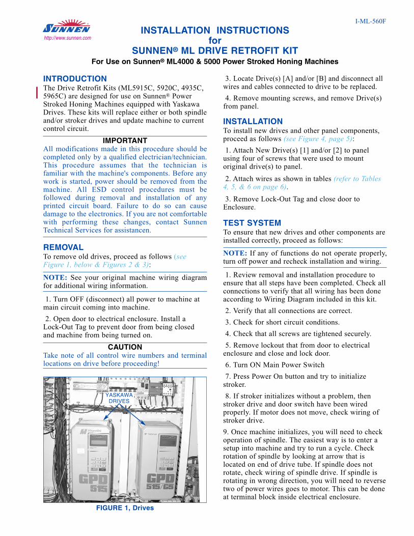
INTRODUCTION The Drive Retrofit Kits (ML5915C, 5920C, 4935C,5965C) are designed for use on Sunnen® PowerStroked Honing Machines equipped with YaskawaDrives. These kits will replace either or both spindleand/or stroker drives and update machine to currentcontrol circuit.
IMPORTANTAll modifications made in this procedure should becompleted only by a qualified electrician/technician.This procedure assumes that the technician isfamiliar with the machine's components. Before anywork is started, power should be removed from themachine. All ESD control procedures must befollowed during removal and installation of anyprinted circuit board. Failure to do so can causedamage to the electronics. If you are not comfortablewith performing these changes, contact SunnenTechnical Services for assistancen.
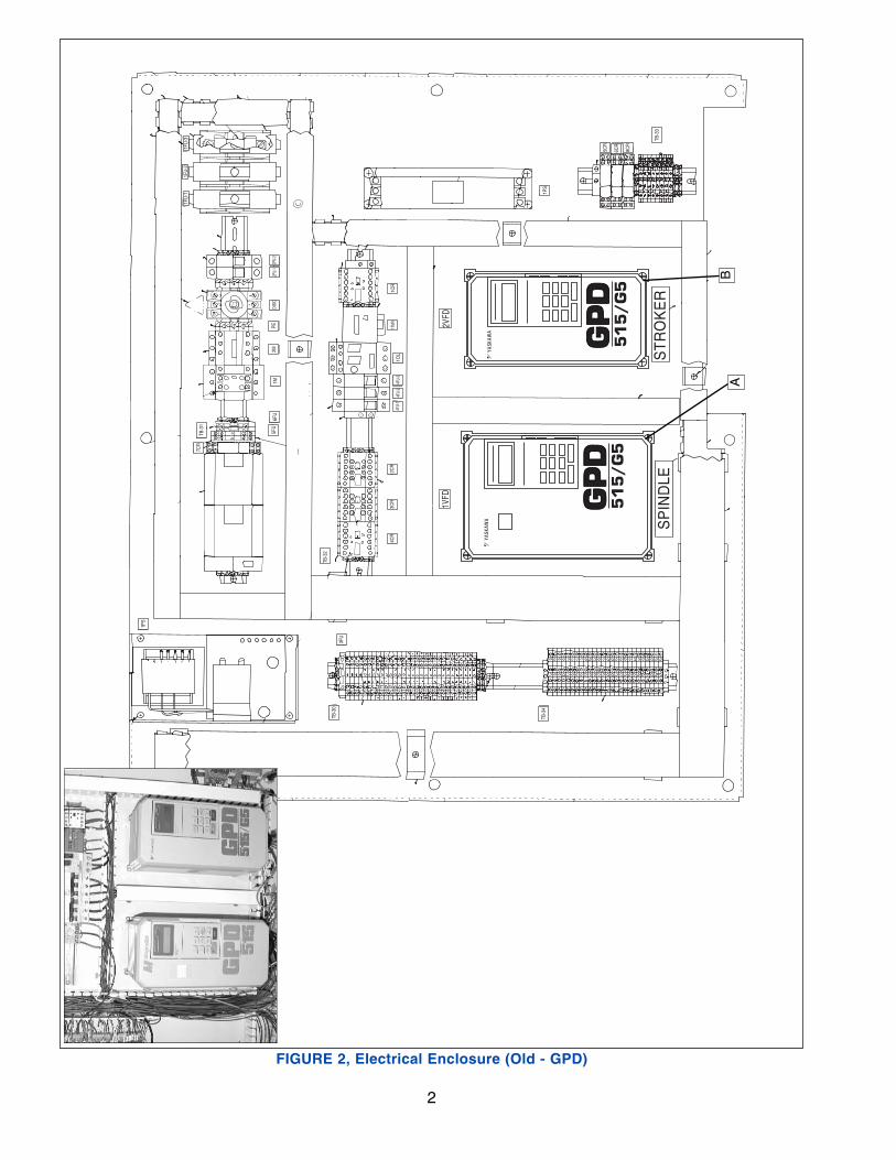
REMOVAL To remove old drives, proceed as follows (seeFigure 1, below & Figures 2 & 3):
NOTE: See your original machine wiring diagramfor additional wiring information.
1. Turn OFF (disconnect) all power to machine atmain circuit coming into machine.
2. Open door to electrical enclosure. Install a Lock-Out Tag to prevent door from being closedand machine from being turned on.
CAUTIONTake note of all control wire numbers and terminallocations on drive before proceeding!
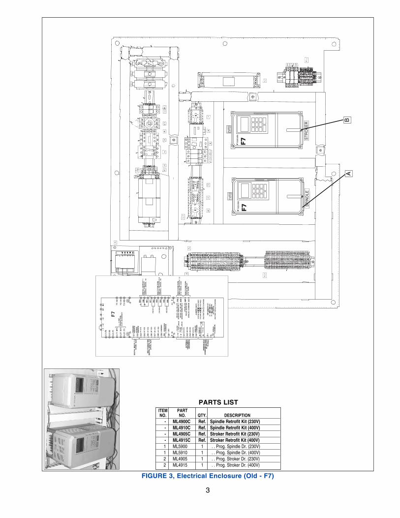
3. Locate Drive(s) [A] and/or [B] and disconnect allwires and cables connected to drive to be replaced.
4. Remove mounting screws, and remove Drive(s)from panel.
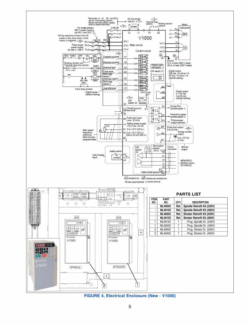
INSTALLATION To install new drives and other panel components,proceed as follows (see Figure 4, page 5): 1. Attach New Drive(s) [1] and/or [2] to panel
using four of screws that were used to mount original drive(s) to panel.
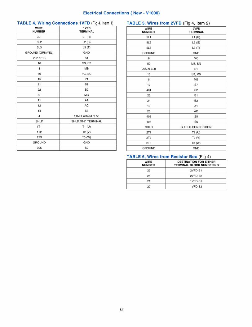
2. Attach wires as shown in tables (refer to Tables4, 5, & 6 on page 6).3. Remove Lock-Out Tag and close door to
Enclosure.
TEST SYSTEM To ensure that new drives and other components areinstalled correctly, proceed as follows:
NOTE: If any of functions do not operate properly,turn off power and recheck installation and wiring.
1. Review removal and installation procedure toensure that all steps have been completed. Check allconnections to verify that all wiring has been doneaccording to Wiring Diagram included in this kit.
2. Verify that all connections are correct.
3. Check for short circuit conditions.
4. Check that all screws are tightened securely.
5. Remove lockout that from door to electricalenclosure and close and lock door.
6. Turn ON Main Power Switch
7. Press Power On button and try to initializestroker.
8. If stroker initializes without a problem, thenstroker drive and door switch have been wiredproperly. If motor does not move, check wiring ofstroker drive.
9. Once machine initializes, you will need to checkoperation of spindle. The easiest way is to enter asetup into machine and try to run a cycle. Checkrotation of spindle by looking at arrow that islocated on end of drive tube. If spindle does notrotate, check wiring of spindle drive. If spindle isrotating in wrong direction, you will need to reversetwo of power wires goes to motor. This can be doneat terminal block inside electrical enclosure.
I-ML-560F
INSTALLATION INSTRUCTIONSfor
SUNNEN® ML DRIVE RETROFIT KITFor Use on Sunnen® ML4000 & 5000 Power Stroked Honing Machines
http://www.sunnen.com
FIGURE 1, Drives
YASKAWADRIVES
2
STR
OK
ER
2VFD
YASK
AWA GP
DG
PD
51
5/
G5
SP
IND
LE
1VFD
YASK
AWA
GP
DG
PD
51
5/
G5
1PS
TB-3
03F
U
TB-3
4
5CR
6CR
TB-3
3
8CR
1PS
1FU
-21F
U-3
1FU
-1
1M6F
U5F
U
7CR
DIS
CPE
2M2F
U-2
2FU-
1
4FU-
24F
U-3
1OL
1TMR
1CR
4FU-
13C
R2C
R4C
R
TB-3
2
TB-3
1
FIGURE 2, Electrical Enclosure (Old - GPD)
AB
3
2VFD
1VFD
STR
OK
ER
SP
IND
LE
YASK
AWA
F7
F7
L11 (R1)
L21 (S1)
L31 (T)
S1
S2
S3
S4
S5
S6
S7
SP
MU
LTI-FU
NC
TIO
ND
IGIT
AL IN
PU
TS 3
-824V
DC
, 8m
A
+1
+2
B1
B2
-V+V
A2
A1
R+
R-
S+
1G
(G)
T1 (
U)
T3 (
W)
T2 (
V)
MC
MB
MA
+3
-
L1 (R)
L2 (S)
L3 (T)
S8
SN
SC
E
+24V
S-
A3
RP
AC
M2
M1
M4
M3
M6
M5
(G)
E
FM
AM
MP
AC
+/- 1
1 B
IT R
ESO
LU
TIO
N,
0.2
% A
CC
URA
CY
DIG
ITA
L O
UTPO
UT 1
FA
ULT C
ON
TA
CT
250V
AC
, 30V
DC
, 1A
MU
LTI-FU
NC
TIO
ND
IGIT
AL O
UTPU
TS 2
-4250V
AC
, 30V
DC
, 1A
MU
LTI-FU
NC
TIO
NA
NA
LO
G O
UTPU
TS 1
-20 t
o 1
0V
DC
, 2m
A
MU
LTI-FU
NC
TIO
NPU
LSE O
UTPU
T0 t
o 3
2kH
z
DIG
ITA
L IN
PU
TS 1
-224V
DC
, 8m
A
(H2-0
2)
(H2-0
1)
(H2-0
3)
(H4-0
1,-02,-03,-07)
AN
ALO
G M
ON
ITO
R 1
(H4-0
4,-05,-06,-08)
AN
ALO
G M
ON
ITO
R 2
AN
ALO
G C
OM
MO
N
(H4-0
6,-07)
PU
LSE M
ON
ITO
R
JU
MPER C
N15
CH
1(F
M)
(VO
LTA
GE)
CH
2(A
M)
(VO
LTA
GE)
I V
(FA
CTO
RY D
EFA
ULTS S
HO
WN
)
DIP
SW
ITC
H S
1S1-1
(OFF)
S1-2
(ON
)
OFF O
N
(FA
CTO
RY D
EFA
ULTS S
HO
WN
)
FORW
ARD
RUN/S
TOP
REVERSE
RUN/S
TOP
(H1-0
2)
(H1-0
1)
(H1-0
3)
(H1-0
5)
(H1-0
4)
(H1-0
6)
SEQ
UEN
CE
CO
MM
ON
CO
MM
ON
+15V
DC
+/-10%
,20m
A-1
5V
DC
+/-10%
,20m
A
(H3-0
1)
(H3-0
9)
(H3-0
5)
(H6-0
1)
AN
ALO
GC
OM
MO
N
TERM
INA
TIN
GRESIS
TO
R
110 o
hm
S1-1O
FF
ON
SIG
NA
LC
OM
MO
N
MO
DBU
S R
TU
CO
MM
UN
ICA
TIO
NS
RS-4
85/4
22
19.2
Kbps
EX
TERN
AL
FREQ
UEN
CY
REFEREN
CE
YASK
AWA
F7
FIGURE 3, Electrical Enclosure (Old - F7)
AB
ITEM PARTNO. NO. QTY. DESCRIPTION
- ML4900C Ref. Spindle Retrofit Kit (230V)- ML4910C Ref. Spindle Retrofit Kit (400V)- ML4905C Ref. Stroker Retrofit Kit (230V)- ML4915C Ref. Stroker Retrofit Kit (400V)1 ML5900 1 . . Prog. Spindle Dr. (230V)1 ML5910 1 . . Prog. Spindle Dr. (400V)2 ML4905 1 . . Prog. Stroker Dr. (230V)2 ML4915 1 . . Prog. Stroker Dr. (400V)
PARTS LIST
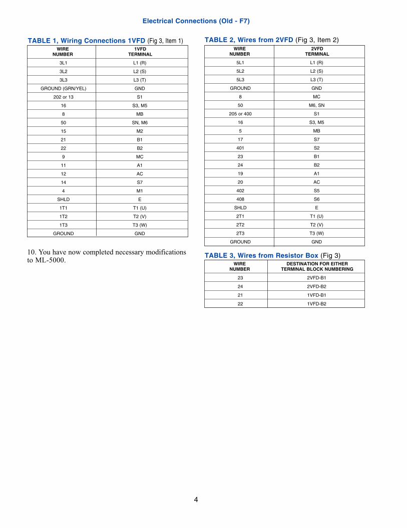
10. You have now completed necessary modificationsto ML-5000.
WIRE 1VFD NUMBER TERMINAL
3L1 L1 (R)
3L2 L2 (S)
3L3 L3 (T)
GROUND (GRN/YEL) GND
202 or 13 S1
16 S3, M5
8 MB
50 SN, M6
15 M2
21 B1
22 B2
9 MC
11 A1
12 AC
14 S7
4 M1
SHLD E
1T1 T1 (U)
1T2 T2 (V)
1T3 T3 (W)
GROUND GND
TABLE 1, Wiring Connections 1VFD (Fig 3, Item 1)WIRE 2VFD
NUMBER TERMINAL
5L1 L1 (R)
5L2 L2 (S)
5L3 L3 (T)
GROUND GND
8 MC
50 M6, SN
205 or 400 S1
16 S3, M5
5 MB
17 S7
401 S2
23 B1
24 B2
19 A1
20 AC
402 S5
408 S6
SHLD E
2T1 T1 (U)
2T2 T2 (V)
2T3 T3 (W)
GROUND GND
WIRE DESTINATION FOR EITHERNUMBER TERMINAL BLOCK NUMBERING
23 2VFD-B1
24 2VFD-B2
21 1VFD-B1
22 1VFD-B2
TABLE 3, Wires from Resistor Box (Fig 3)
TABLE 2, Wires from 2VFD (Fig 3, Item 2)
Electrical Connections (Old - F7)
4
5
STROKER SPINDLE
2VFD
YASKAWA
V1000
FSC
RESET ENTER
STOPRUN
1VFD
YASKAWA
V1000
FSC
RESET ENTER
STOPRUN
FIGURE 4, Electrical Enclosure (New - V1000)
ITEM PARTNO. NO. QTY. DESCRIPTION
- ML4900C Ref. Spindle Retrofit Kit (230V)- ML4910C Ref. Spindle Retrofit Kit (400V)- ML4905C Ref. Stroker Retrofit Kit (230V)- ML4915C Ref. Stroker Retrofit Kit (400V)1 ML5915C 1 . . Prog. Spindle Dr. (230V)1 ML5920C 1 . . Prog. Spindle Dr. (400V)2 ML4905C 1 . . Prog. Stroker Dr. (230V)2 ML4940C 1 . . Prog. Stroker Dr. (400V)
PARTS LIST
12
6
Electrical Connections ( New - V1000)
WIRE 2VFDNUMBER TERMINAL
5L1 L1 (R)
5L2 L2 (S)
5L3 L3 (T)
GROUND GND
8 MC
50 M6, SN
205 or 400 S1
16 S3, M5
5 MB
17 S7
401 S2
23 B1
24 B2
19 A1
20 AC
402 S5
408 S6
SHLD SHIELD CONNECTION
2T1 T1 (U)
2T2 T2 (V)
2T3 T3 (W)
GROUND GND
WIRE DESTINATION FOR EITHERNUMBER TERMINAL BLOCK NUMBERING
23 2VFD-B1
24 2VFD-B2
21 1VFD-B1
22 1VFD-B2
TABLE 6, Wires from Resistor Box (Fig 4)
TABLE 5, Wires from 2VFD (Fig 4, Item 2)WIRE 1VFD
NUMBER TERMINAL
3L1 L1 (R)
3L2 L2 (S)
3L3 L3 (T)
GROUND (GRN/YEL) GND
202 or 13 S1
16 S3, P2
8 MB
50 PC, SC
15 P1
21 B1
22 B2
9 MC
11 A1
12 AC
14 S7
4 1TMR instead of 50
SHLD SHLD GND TERMINAL
1T1 T1 (U)
1T2 T2 (V)
1T3 T3 (W)
GROUND GND
305 S2
TABLE 4, Wiring Connections 1VFD (Fig 4, Item 1)
STROKER SPINDLE
2VFD
YASKAWA
A1000
FSC
RESET ENTER
STOPRUN
1VFD
YASKAWA
V1000
FSC
RESET ENTER
STOPRUN
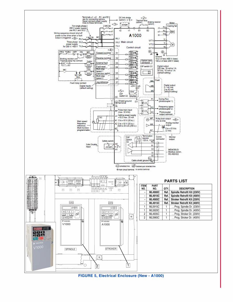
FIGURE 5, Electrical Enclosure (New - A1000)
ITEM PARTNO. NO. QTY. DESCRIPTION
- ML4900C Ref. Spindle Retrofit Kit (230V)- ML4910C Ref. Spindle Retrofit Kit (400V)- ML4905C Ref. Stroker Retrofit Kit (230V)- ML4915C Ref. Stroker Retrofit Kit (400V)1 ML5915C 1 . . Prog. Spindle Dr. (230V)1 ML5920C 1 . . Prog. Spindle Dr. (400V)2 ML4935C 1 . . Prog. Stroker Dr. (230V)2 ML5965C 1 . . Prog. Stroker Dr. (400V)
PARTS LIST
12
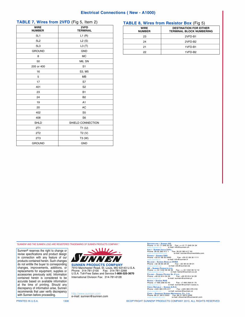
Electrical Connections ( New - A1000)
PRINTED IN U.S.A. 1308 ©COPYRIGHT SUNNEN® PRODUCTS COMPANY 2013, ALL RIGHTS RESERVED
SUNNEN PRODUCTS COMPANY7910 Manchester Road, St. Louis, MO 63143 U.S.A.Phone: 314-781-2100 Fax: 314-781-2268U.S.A. Toll-Free Sales and Service:1-800-325-3670International Division Fax: 314-781-6128
http://www.sunnen.come-mail: [email protected]
SWITZERLAND – SUNNEN AGPhone: ++ 41 71 649 33 33 Fax: ++ 41 71 649 34 34www.sunnen.ch e-mail: [email protected] - SUNNEN ITALIA S.R.L.Phone: 39 02 383 417 1 Fax: 39 02 383 417 50www.sunnenitalia.com e-mail: [email protected] – SUNNEN SASPhone: +33 01 69 30 0000 Fax: +33 01 69 30 1111 www.sunnen.fr e-mail: [email protected] BELGIUM – SUNNEN BENELUX BVBA Phone: +32 38 80 28 00 Fax: +32 38 44 39 01 www.sunnen.be e-mail: [email protected] UK – SUNNEN PRODUCTS LTD.Phone: ++ 44 1442 39 39 39 Fax: ++ 44 1442 39 12 12www.sunnen.co.uk e-mail: [email protected] POLAND – SUNNEN POLSKA SP. Z O.O. Phone: +48 22 814 34 29 Fax: +48 22 814 34 28 www.sunnen.pl e-mail: [email protected] – SUNNEN RUS Phone: +7 495 258 43 43 Fax: +7 495 258 91 75 www.sunnen.ru e-mail: [email protected] CZECH REPUBLIC – SUNNEN S.R.O. Phone: +420 383 376 317 Fax: +420 383 376 316 www.sunnen.cz e-mail: [email protected] – SHANGHAI SUNNEN MECHANICAL CO., LTD.Phone: 86 21 5813 3322 Fax: 86 21 5813 2299www.sunnensh.com e-mail: [email protected]
Sunnen® reserves the right to change orrevise specifications and product designin connection with any feature of ourproducts contained herein. Such changesdo not entitle the buyer to correspondingchanges, improvements, additions, orreplacements for equipment, supplies oraccessories previously sold. Informationcontained herein is considered to beaccurate based on available informationat the time of printing. Should any discrepancy of information arise, Sunnenrecommends that user verify discrepancywith Sunnen before proceeding.
“SUNNEN® AND THE SUNNEN LOGO ARE REGISTERED TRADEMARKS OF SUNNEN PRODUCTS COMPANY.”
WIRE 2VFDNUMBER TERMINAL
5L1 L1 (R)
5L2 L2 (S)
5L3 L3 (T)
GROUND GND
8 MC
50 M6, SN
205 or 400 S1
16 S3, M5
5 MB
17 S7
401 S2
23 B1
24 B2
19 A1
20 AC
402 S5
408 S6
SHLD SHIELD CONNECTION
2T1 T1 (U)
2T2 T2 (V)
2T3 T3 (W)
GROUND GND
WIRE DESTINATION FOR EITHERNUMBER TERMINAL BLOCK NUMBERING
23 2VFD-B1
24 2VFD-B2
21 1VFD-B1
22 1VFD-B2
TABLE 8, Wires from Resistor Box (Fig 5)TABLE 7, Wires from 2VFD (Fig 5, Item 2)