Embed Size (px)
Citation preview

iMarktrade Microplate Absorbance Reader
Instruction Manual
i
Warranty Statement This warranty may vary outside of the continental United States Contact your local Bio-Rad office for the exact terms of your warranty
Bio-Rad Laboratories warrants to the customer that the iMark Microplate Absorbance Reader will be free from defects in material and workmanship and will meet all performance specifications for a period of one year from the date of shipment This warranty covers all parts and labor
In the event that the instrument must be returned to the factory for repair under warranty the instrument must be packed for return in original packaging Please contact your local Bio-Rad representative for the necessary return documents The required documentation includes a decontamination certificate
Bio-Rad shall not be liable for any incidental special or consequential loss damage or expense directly or indirectly arising from the use of the iMark Microplate Absorbance Reader Bio-Rad makes no warranty whatsoever in regard to products or parts furnished by third parties such being subject to the warranty of their respective manufacturers Service under this warranty shall be requested by contacting your nearest Bio-Rad office
The following items are considered customer-installable consumables thermal printer paper and light bulbs These parts are not covered by this warranty All customer-installed parts are warranted only to be free from defects in workmanship This warranty does not extend to any instrument or parts thereof that have been subject to misuse neglect or accident or that have been modified by anyone other than Bio-Rad or that have been used in violation of Bio-Rad instructions
The foregoing obligations are in lieu of all other obligations and liabilities including negligence and all warranties of merchantability fitness for a particular purpose or otherwise expressed or implied in fact or by law and state Bio-Radrsquos entire and exclusive liability and buyerrsquos exclusive remedy for any claims or damages in connection with the furnishing of goods or parts their design suitability for use installation or operation Bio-Rad will in no event be liable for any special incidental or consequential damages whatsoever and Bio-Radrsquos liability under no circumstances will exceed the contract price for the goods for which liability is claimed
ii
Regulatory Notices Electro Magnetic Compatibility This instrument is designed to meet the Class-A emissions and immunity levels of the EN 61326 product family standard for the CE mark This rating requires that it only be used in a laboratory environment
NOTE These limits are designed to provide reasonable protection against harmful interference when the equipment is operated in a commercial environment This equipment generates uses and can radiate radio frequency energy and if not installed and used in accordance with the instruction manual may cause harmful interference to radio communications Operation of equipment in a residential area is likely to cause harmful interference in which case the user will be required to correct the interference at hisher own expense
Safety This instrument is designed to meet EN 61010-1 requirements for the CE mark which are internationally accepted safety standards for electrical equipment for measurement control and laboratory use EN 61010-1 applies to equipment which is used under the following conditions
bull Indoor use
bull Altitude up to 2000 m
bull MAINS supply voltage fluctuations up to plusmn10
This instrument has been tested and its compliance has been confirmed under the following environmental conditions
bull Overvoltage category II
bull Pollution degree 2
If the instrument is used in a manner not specified in this manual the protection provided by the instrument may be impaired This instrument should not be modified or altered in any way Alteration of this instrument will result in the following
bull Void the manufacturersquos warranty
bull Void regulatory compliance
bull Create a potential safety hazard
Protective Ground This instrument has a detachable three-wire power cord for connection to both the power source and protective ground The protective ground contact is connected to the accessible metal parts of the instrument To prevent electrical shock always use a power source outlet that has a properly grounded protective-ground contact
iii
Table of Contents Introduction 1
Description 1 USB Interface 1 Built-in Printer 1 External Features3 Keypad Guide 4
Instrument Setup 5
Unpacking the Instrument5 Initial Instrument Startup5 Instrument Shutdown 6
Software Overview 7
Capabilities7 Quick Guide to Reading a Plate 7
Instrument Functions 8
Calculations 8 Security password8 Memory Back-Up8 Limits 9
Report Types 10
End-point Protocol Reports10 1 Raw data report10 2 Absorbance report 10 3 Limit report 10 4 Matrix report 10 5 Cutoff report 11 6 Curve Fit Report 12 7 Concentration Report12 8 Difference Report12 9 TeSeE Screening Report 13
Kinetic Protocol Reports 15 1 Absorbance Report 15 2 Kinetic Plots Report 15 3 Linear Regression Report 15 4 GALT Report 15
iv
Screen by Screen Procedures 17
Initial Startup 17 Configuring the System18 Printing Reports and Protocol information20 Memory Recall Operation 21 Editing the Kinetic Protocol22 Checkmark Value Setting (Administrator only) 24 Editing End Point Protocol 25 Cutoff Setting Procedure 26 Standard Setting Procedure 29 Mode Setting Procedure 32 Plate Map Setting Procedure 33
Instrument Maintenance 36
Installing Interference Filters 36 Changing the Lamp 36
Troubleshooting and Error Messages 37
Instrument Specifications 39
iMark Microplate Absorbance Reader Instruction Manual
1
Introduction Description The iMarktrade Microplate Absorbance Reader (catalog 168-1130) is an eight-channel vertical pathlength photometer that measures the absorbance of the contents in the wells of a 96-well microtitration plates It can perform single or dual wavelength measurements and can report absorbance values to three decimal places
The iMark reader can be programmed by entering commands through the membrane keypad to define plate reading and data analysis parameters as testing protocols and select report types Hard copy reports can be produced by an optional on-board thermal printer or external printer
The iMark reader can also be controlled by the Windows-based Microplate Managerreg software (catalog 168-9520) program through its built-in USB 20 interface device Microplate Manager software provides a complete user-friendly solution for protocol programming as well as data analysis for all microplate absorbance readers from Bio-Rad Laboratories
USB Interface The iMark Microplate Reader has a built-in USB interface This allows external computers to control the instrument When an external computer is in control of the microplate reader the printer and the membrane keys except for the StartStop and OpenClose keys are automatically deactivated and the LCD display appears as below The reader will remain in remote control mode until it is released or until the StartStop key is pressed on the reader
Built-in Printer The iMark Microplate Reader has a built-in printer It can generate all types of reports including graphs and kinetic plots
Remote mode
iMark Microplate Absorbance Reader Instruction Manual
2
Catalog Description 168-1130 iMark Microplate Absorbance Reader with built-in printer 168-1135 iMark Microplate Absorbance Reader with built-in printer
including Microplate Manager 6 software 168-6940 Checkmark Absorbance Reader Performance Validation Kit Accessories Catalog Description 168-1011 405 nm filter 168-1013 415 nm filter 168-1020 450 nm filter 168-1028 490 nm filter 168-1038 540 nm filter 168-1040 550 nm filter 168-1044 570 nm filter 168-1049 595 nm filter 168-1054 620 nm filter 168-1056 630 nm filter 168-1061 655 nm filter 168-1080 750 nm filter 168-1006 Replacement lamp for iMark Microplate Absorbance Reader 168-2007 Replacement printer paper package contains 3 rolls Custom filters between 400 and 750 nm may be ordered Corresponding catalog numbers can be found on wwwbio-radcom or you can order by specifying the wavelength and the model number of the reader
Checkmark Absorbance Reader Performance Validation Kit (catalog item 168-6940) consists of a plate with absorbance standards and software to calculate the accuracy and precision of the iMark Microplate Absorbance Reader
iMark Microplate Absorbance Reader Instruction Manual
3
External Features
Release latch for rear cover Rear cover
Printer slot Power button
Liquid crystal display (LCD)
Keypad
Reading chamber door
Power cord receptacle Serial number label
Cooling vents and fan
USB 20 interface
iMark Microplate Absorbance Reader Instruction Manual
4
Keypad Guide Main Returns to MAIN SCREEN StartStop Initiates plate reading using current active protocol Stops plate reading and printing Paper Feed Advances paper strip in internal printer Print Prints out the plate data and protocol information Edit Enters the Edit Menu and sets up the instrument Memory Recall Reads out protocol and plate data OpenClose Opens or closes the reading chamber door Up Arrow Moves the cursor upward Selects the alphabet or the symbol Left Arrow Returns to the previous screen Moves the cursor to the left Down Arrow Moves the cursor downward Selects the alphabet or the symbol Right Arrow Moves the cursor to the right Changes or selects the value and type Enter Completes or seals a field entry
DotFunction Inputs the dot Changes the input mode Ten Keys Inputs numbers or well type in plate mapping
0 EMP Empty 5 QC QC control 1 SMP Sample 6 CAL Calibrator 2 BLK Blank 7 CP Positive Control 3 STD Standard 8 CN Negative Control 4 CO Cutoff control 9 CW Weak Positive Control
OpenClose Edit
Print Paper Feed Main
START
STOP
Memory Recall
7 CP
8CN
9CW
4 CO
5QC
6CAL
2BLK
3STD
0 EMP
0FUNC
SMP
1
Change
ENTER
Back
Z = A gt
A = Z gt + minusbullbull
iMark Microplate Absorbance Reader Instruction Manual
5
Instrument Setup Unpacking the Instrument The shipping carton contains the following items
bull iMarktrade Microplate Reader with 415 nm 450 nm 490 nm 595 nm 655 nm and 750 nm interference filters installed on the filter wheel
bull Power cord
bull USB cable
bull Dust cover
bull Instruction manual
bull Warranty card
bull One roll of thermal printer paper
Inspect the exterior of the instrument for any signs of shipping damage Contact your local Bio-Rad representative if any of these items are damaged or missing
Initial Instrument Startup 1 Place the instrument on a clean sturdy table or bench It is important to keep the instrument in a clean
relatively dust free environment to ensure optimal performance
2 Connect the power cord to the back of the instrument Before connecting the instrument to the main electrical supply check that the AC voltage is appropriate for the instrument
3 To turn the power on press the green power button on the top of the instrument The LCD will display the version number of the on-board firmware After about three seconds the instrument will perform an initial self-diagnosis that requires about fifteen seconds The login screen displays for you to choose your user level (administrator or common user) and enter the password (initial password 00000) Please allow three minutes for the instrument to warm up (reach thermal equilibrium) before reading plates
Change password Select ldquoChange Passwordrdquo in the Security Menu
Enter the current Password then move the cursor to the 3rd line and enter a new password Press Enter to complete the field entry The system will return to the previous Security Menu
Change user mode Select ldquoChange userrdquo in the Security Menu
Select a desired user mode by pressing the Right Arrow key Enter the appropriate password for the selected user mode Press Enter to complete the field entry The system will return to the previous Security Menu
System Login User Administrator Password Press ENTER
iMark Microplate Absorbance Reader Instruction Manual
6
4 Install the printer paper The thermal printer paper is printable on one side only and must be properly installed for the printer to function The outside of the roll is the printable side
a Open the rear cover of the instrument b Tear off a small piece at the beginning of a new roll at an angle to form
a point c Place the roll of paper in the small pan-like holder positioned below
the printer The roll should be positioned so that it will feed from the bottom
d While pressing the PAPER FEED key feed the pointed end of the paper into the paper feed slot in the underside of the printer until the printer grabs the paper and feeds it through the slot in the top of the instrument
e Securely close the rear compartment
Multi-language support The iMark LCD can produce text in three languages English Russian and Chinese To switch to English from Russian or Chinese press the Main button then the Edit button to get to the configuration screen Press the downward-pointing arrow on the key pad six times to navigate to the language options line Press Enter twice to select English and then press Enter a third time to shut down the reader When restarted the iMark will display in English
Instrument Shutdown To shut down the instrument press the green power button on the top of the instrument for a few seconds Then the LCD will display a Power off Yes or No screen Select ldquoYesrdquo to shut down the instrument
Power off gtgtYes No
iMark Microplate Absorbance Reader Instruction Manual
7
Software Overview Capabilities The iMark Microplate Reader has on-board software that allows the user to set the plate reading and data analysis conditions to save these settings as a test protocol to read a microplate under this protocol and to print reports from the built-in printer The software communicates through the 4-line 20-character LCD and is controlled through the instruments membrane keypad
The software has three different protocol types End-point analysis Kinetic analysis and Checkmark validation The Checkmark validation function is used only by the administrator to verify quality control
The display shows the current mode The user can choose between these protocol types or can press the Memory Recall key to use the current protocol type
Quick Guide to Reading a Plate 1 Turn on the instrument Allow about 30 seconds for self-diagnosis The instrument needs to warm up for
about three minutes prior to reading a plate
2 Upon power up the login screen will appear Enter the login password (initial password 00000) press Enter
3 Program a protocol for your assay See page 22 for information on Editing a Kinetic protocol or page 25 for Editing an End Point Protocol Make sure filters installed correlate with information entered in reader firmware
4 Select the protocol of choice if programmed See the Memory Recall section on page 21 for detailed operation
5 Review or print parameters set in the protocol See the Editing End Point Protocol section on page 25 for details
6 Verify settings on Cutoff Report Limit STDs Mode Mapping and kit name parameters are as desired
7 Protocol setting can be printed see the Printing Reports and Protocols section on page 20 for information
8 All reports other than the raw data report require plate mapping Set the plate map with instructions from the Plate Map Setting Procedure section on page 33
9 The Matrix and Limit reports require assignment of upper and lower limits Set the upper and lower limits in the Editing End Point Protocol Limit setting window
10 The Cutoff report requires definition of the cutoff setting Refer to the Cutoff Setting Procedure section on page 26
11 The Curve fit and Concentration reports require that standard concentration and locations must be defined Refer to page 29 for details on how to define the standards and the curve fit parameters
12 Set the general reading mode (single or dual wavelength reading plate shaking read mode) following the instructions in the Mode Setting Procedure section on page 32
After warm-up is complete
13 Press the ldquoMainrdquo key The main screen appears on the LCD
14 Carefully place the microplate in the reading chamber Press the ldquoStartStoprdquo key to read
iMark Microplate Absorbance Reader Instruction Manual
8
Instrument Functions Calculations The Microplate Reader uses Beers Law to calculate the absorbance value of each well Beers Law states that absorbance is equal to the log10 of the ratio of the baseline measurement intensity (Io) to the sample measurement intensity (I)
Beers Law Absorbance = Log10 (IoI)
Before measuring the plate the reader takes a reading for all eight photodiode channels These values are recorded as the baseline measurement (Io) values for each channel respectively The reader then records the sample measurement (I) value for each well and calculates the absorbance using these values Channel-to-channel error is significantly reduced because the Io value for a given channel is used only in determining the absorbance of the wells of that channel
Security password The iMark Microplate Reader requires a user login with password This security feature helps to prevent any unwarranted modifications to the analysis conditionsprotocols and data stored in the instrument and identifies the operator on reports The reader has two user settings the Administrator and the Common user Each user level has its own security password
Memory Back-Up The battery back-up provides memory even after the reader is turned off
The following information will be saved in the memory until new reading parameters are set by the user or a new plate is read by the instrument Note that if a run is aborted before it is finished all the previous plate reading data remain in memory and none of the data from the aborted reading is stored
bull The ten latest sets of End-point protocol plate reading results
bull The two latest sets of Kinetic plate reading results (max 30 series of readings for each Kinetic Protocol)
bull 64 End-point Protocol settings and 2 Kinetic Protocol settings
bull A set of Checkmark reference data and the one latest set of Checkmark reading result
bull A set of standard curve data for the storage of standard curves and graphs
bull Eight wavelength values for filters
bull Laboratory name
bull Two security passwords (for the Administrator and the Common user)
bull Instrument serial number
In addition to the battery back-up memory the instrument has a small amount of non-volatile memory to keep the system information after the battery is dead The serial number is stored in this memory The average battery life is 5 years
iMark Microplate Absorbance Reader Instruction Manual
9
The first time the instrument is turned on or after a battery failure the following default information is held in the memory
1 Both Administrator and Common user security passwords are set to 00000
2 Laboratory name is Bio-Rad Laboratories
3 All wavelength values of the filters are set to --- nm
4 The date and time of the calendar chip are set to 1 day 1 month 00 year 0 hour and 0 minute
5 No plate reading data is available
6 End-point protocol is chosen and the protocol number is set to 1
7 No standard curve data for the storage of standard curves and graphs is available
Limits The Microplate Reader displays absorbance readings with absolute values as 3500 Out-of-range absorbance values (those with absolute values greater than 3500) are displayed as either or - For example if the absorbance is 4500 then the display will read and if the absorbance is -4500 the display will read -
iMark Microplate Absorbance Reader Instruction Manual
10
Report Types Two types of reports can be generated End-point protocol and Kinetic protocol Each of these and their subtypes are described below After these descriptions there are flow diagrams that show how to access specific choices
End-point Protocol Reports Nine types of End-Point Protocol reports can be generated raw data absorbance limit matrix cutoff curve fit concentration difference and TeSeE screening reports
1 Raw data report The Raw data report is the uncorrected absorbance values (without blank subtraction) In single-wavelength mode the reported value is the measured absorbance In dual-wavelength mode the reported value is the difference between the uncorrected readings taken with the measurement filter and with the reference filter
2 Absorbance report The Absorbance report is the blank-corrected absorbance values The mean absorbance value of all of the wells designated as assay blanks is calculated and then subtracted from all 96 values of the raw data set to produce the Absorbance report
Abs = Raw ndash Blank mean
Blank mean = Xn
SD = [X^2 ndash n(Blank mean)^2n-1]^12
Where
SD = Standard deviation
X = Sum total of the raw absorbance for each blank
X^2 = Sum total of the squared raw absorbance for each blank
n = Number of blanks
3 Limit report The Limit report provides a qualitative YESNO report Wells with blank-subtracted absorbance values between the upper and lower limits are represented with an asterisk () wells with absorbance values below the lower limit by minus signs (-) and wells with absorbance values greater than the upper limit by positive signs (+)
4 Matrix report The Matrix report provides a qualitative report of the relative magnitude of the absorbance values on the plate The absorbance range defined by the upper and lower limits is divided into 10 equal partitions numbered 0 through 9 The blank-subtracted absorbance value of each well is classified according to the partition of the matrix to which it corresponds and is reported as a signal digit Wells with absorbance values greater than the upper limit are reported by plus signs (+) and wells with absorbance values less than the lower limit by minus signs (-)
iMark Microplate Absorbance Reader Instruction Manual
11
5 Cutoff report The Cutoff report provides a qualitative report of the relative magnitude of the absorbance values or converted concentrations on the plate
Four types of cutoff reports are supported ranged constant single constant formula and ratio These and their subtypes are listed below
a Ranged Constant The user inputs Positive and Negative values to be used as the cutoff
For units designated Abs if the absorbance of a well is within the positive and negative cutoff values the well is scored If the absorbance of a well is greater than the positive value the well is scored + and if the absorbance of a well is below the negative value the well is scored -
For units not designated Abs the absorbance value of each well is converted to the concentration value using the curve fit constants of the curve fit report If the concentration of a well is within the positive and negative cutoff values the well is scored If the concentration of a well is greater than the positive value the well is scored + and if the concentration of a well is below the negative value the well is scored -
b Single Constant The user inputs Positive and Gray zone values to be used as the cutoff
For units designated Abs if the absorbance of a well is within the gray zone value of the positive cutoff value the well is scored If the absorbance of a well is more than the gray zone value and greater than the positive value the well is scored + and if the absorbance of a well is more than the gray zone value below the positive value the well is scored -
Upper cutoff absorbance = Positive absorbance + ((Gray zone100) Positive absorbance)
Lower cutoff absorbance = Positive absorbance ndash ((Gray zone100) Positive absorbance)
For units not designated Abs the absorbance value of each well is converted to the concentration value using the curve fit constants of the curve fit report If the concentration of a well is within the gray zone value of the positive cutoff value the well is scored If the concentration of a well is more than the gray zone value greater than the positive value the well is scored + and if the concentration of a well is more than the gray zone value below the positive value the well is scored -
Upper cutoff conc = Conc of positive controls + ((Gray zone100) Conc of positive controls)
Lower cutoff conc = Conc of positive controls - ((Gray zone100) Conc of positive controls)
c Formula The mean absorbance values of the Positive and Negative wells defined in the plate map are used for the cutoff formula calculation
The 12 types of formula-based cutoff reports are
i k CNx vii k + CNx
ii k CPx viii k + CPx
iii k COx ix k + COx
iv CNx k x kCNx + CPx
v CPx k xi xi (CNx + CPx) k
vi COx k xii k1CNx + k2CPx
iMark Microplate Absorbance Reader Instruction Manual
12
The result absorbance value of the formula calculation and the gray zone value that is entered by the user are used for the cutoff
The upper and lower cutoff values are
Upper cutoff absorbance = Result of a Formula + ((Gray zone100) Result of a Formula)
Lower cutoff absorbance = Result of a Formula - ((Gray zone100) Result of a Formula)
The absorbance range of the upper and lower cutoff is divided into 10 equal partitions numbered 0 through 9 The absorbance value of each well is classified according to the partition of the matrix to which it corresponds and is reported as a signal digit Wells with absorbance values greater than the upper cutoff are reported by plus signs (+) and wells with absorbance values less than the lower cutoff by minus signs (-)
d Ratio The mean absorbance value of the Calibrator wells defined in the plate map and the concentration value entered by the user are used for the cutoff ratio Before the cutoff the absorbance value of each well is converted into the concentration value The ratio of ConcentrationAbsorbance of Calibrator is applied to the conversion Then the cutoff is done with the defined Positive and Negative or the defined Positive and Gray zone values
6 Curve Fit Report The Curve fit report provides a regression analysis based on the absorbance values of a series of standards There are ten types of curve fits supported with the onboard software on iMark Microplate readers
i 5P Logistic Rodbard ii 4P Logistic Rodbard iii 5P Logistic Cook-Wilkenson iv 4P Logistic Cook-Wilkenson v 5P Exponential vi Sigmoid Logistic vii Linear regression viii Quadratic regression ix Cubic x Point-To-Point regression
The onboard software calculates the best fit of the defined curve between each set of two consecutive data points in the standard curve of absorbance vs concentration And then it generates the report with the coefficients of regression the correlation coefficient and the standard error
For readers with the optional internal printer or with an external ESCP printer which accepts ESCP code a graph of the standard curve may be generated when selected in the report parameter
7 Concentration Report In case of the curve fit the Concentration report also provides the regression analysis After the calculation of the curve fit it calculates the concentrations values of the samples and generates the report
In case of the cutoff constant with the unit not designated Abs and in case of the cutoff ratio the reader generates the list of concentration of each well
8 Difference Report The Difference report is the subtraction report between the neighboring columns or row
iMark Microplate Absorbance Reader Instruction Manual
13
9 TeSeE Screening Report Analysis of the TeSeE screening assay results can be done with two pre-programmed protocols ldquoTeSeErdquo protocol is stored in Endpoint Protocol position 5 and ldquoTeSeE eqrdquo is stored in Endpoint Protocol position 6 as factory default setting Both protocols are locked
TeSeE screening report is generated only if these protocols are selected as current active protocol Plate is first validated according to negative and positive controls validation criteria samples are then compared to the calculated cut-off
Criteria for plate validation are set as follows
Criteria 1 Individual Negative Control must be lt 0150
Number of valid Negative Control must be gt= 3
Criteria 2 Individual Negative Control must be lt 1400 Negative Control average
Number of valid Negative Control must be gt= 2
Criteria 3 Positive Control average must be gt= 1000
Cutoff is calculated as follows
TeSeE
Positive cutoff = Negative Control average + 0210
Negative cutoff = (Negative Control average + 0210) 0900
TeSeE eq
Positive cutoff = Negative Control average + 0210
Negative cutoff = Negative Control average + 0090
Samples are interpreted as follows
ldquoPOSrdquo Positive when sample OD gt= Positive cutoff
ldquoNEGrdquo Negative when sample OD lt Negative cutoff
ldquordquo Gray zone NEG cutoff =lt sample OD lt POS cutoff
iMark Microplate Absorbance Reader Instruction Manual
14
Protocol
Security
Filters
Date Set
Lab name
Cutoff
Report
Limit
STDs
Mode
Mapping
Kit name
Not Used
Constant
Control
Formula
Ratio
Ranged Cutoff Single Cutoff
Ranged Cutoff Single Cutoff
12 choices of cutoff formula
Concentration
Unit
Cutoff value
Cutoff Values setting Gray zone setting when single cutoff
Cutoff Control setting Gray zone setting when single cutoff
Coefficient setting of selected formula
0 - 9999
17 choices of unit
Cutoff Values setting Gray zone setting when single Cutoff
Ranged Cutoff Single Cutoff
Raw(Raw data) Abs(Absorbance) Lim(Limit) Mtx(Matrix) Cut(Cutoff) Crv(Curve fit) Cnc(Concentration) Dif(Difference)
Upper Limit Lower Limit For Limit Report
Standard information
Curvefit
Number of STD Concentration
Unit
Curvefit type Graph axis
Set Photo mode Set Shaking
Set Read mode
Manual mapping
Automatic mapping
Change password
Change user
End-point Analysis Protocol
Up to 12 Standards 0 to 9999 17 choices
12 choices of curve fit type 4 choices of graph axis combination of Log and Linear
SingleDual Wavelength Shake (Yes No) Speed (High Low Mid) Time Read Speed (FastStep) and Read Mode (NormalEval)
Func key to switch [N] to [F] [N] for sample number [F] for sample
Func key to switch from [ABC] to [abc] to [sym] key to move cursor
For current user mode Administrator or common user Administrator has power to switch
Filter wavelength setting for 1-8 positions ldquo0rdquo for no filter
DayMonthYear HourMin
Func key to switch from [ABC] to [abc] to [sym] key to move cursor
Save STDC
Language
Save STD Curve
Rename STD Curve
Select Language
5 choices of storage number
5 choices of STD curve
Func key to switch from [ABC] to [abc] to [sym] key to move cursor
Choices of pre-installed language for LCD and report printout
BlankCNCWCPCOQCCalibratorSampleReplicate well
Recall Setting Select STD Curv
Recall YesNo Selection 5 choices of memorized STD curve
Edit
Bold for menu pages
LCD adj and key to change contrast
Italic for program pages
iMark Microplate Absorbance Reader Instruction Manual
15
Kinetic Protocol Reports Four types of Kinetic protocol reports can be generated absorbance kinetic plots linear regression and GALT reports
1 Absorbance Report The Kinetic Absorbance report is the series of absorbance data in the kinetic sequence
2 Kinetic Plots Report The Kinetic plots are the absorbance plots of each well in the plate It is available for readers with the optional internal printer or with an external ESCP printer which accepts ESCP code
3 Linear Regression Report The Linear Regression report provides the calculation of Kinetic reaction rate for each well using the linear regression
4 GALT Report The GALT report calculates the following formula for each well between two readings of a plate
GALT = (R2 ndash R1) k
Where R1 = Absorbance value of 1st reading
R2 = Absorbance value of 2nd reading
k = GALT factor
iMark Microplate Absorbance Reader Instruction Manual
16
Func key to switch from [ABC] to [abc] to [sym] key to move cursor
Func key to switch from [ABC] to [abc] to [sym] key to move cursor
Func key to switch from [ABC] to [abc] to [sym] key to move cursor
DayMonthYear HourMin
Filter wavelength setting for 1-8 positions ldquo0rdquo for no filter
Edit
Kinetic Analysis Protocol
Protocol
Security
Filters
Date Set
Lab Name
Change password
Change user
LockUnlock
Mode
Report
Calc
Mapping
Assay
Kit name
Reading Inter
Shaking Phmode
Speed
Number of reads (2-30) start delay time (0-999) Reading interval time Shake (FirstEverydisable) Speed (High Low Mid) Time Single Dual wavelength Read Speed (FastStep)
CC Limit (correlation coefficient limit) Calcrange (calculation range of reading number) for Linear regression Report
GALT factor k input (0- 9999) Result = (2nd read ndash 1st read)k for GALT Report
Manual mapping
Automatic mapping
Func key to switch [N] to [F] [N] for sample number [F] for sample type
General Kinetic or GALT assay assay type selection
Absorbance KINETIC Plots Linear regression when General Kinetic Assay selected GALT report when GALT Kinetic assay selected
For current user mode Administrator or Common user Administrator has power to switch
Special Buttons
Memory Recall
Main
Protocol Plate Data
Report Protocol
End point Kinetic
Checkmark
1-64 End point protocol storage 1-2 Kinetic protocol storage Checkmark reader test
Printout
Returns to MAIN screen
SaveSTDC
Language
BlankCNCWCPCOQCCalibratorSampleReplicate well
Save STD Curve
Rename STD Curve
Select Language
5 choices of storage number
5 choices of STD curve
Choices of pre-installed language for LCD and report printout
Bold for menu pages
LCD adj and key to change contrast
Italic for program pages
iMark Microplate Absorbance Reader Instruction Manual
17
Screen by Screen Procedures Initial Startup
01Kinetic-1 M405(1)R605(6)30read Shake999sMidEvery 382402 180901
End point mode
Kinetic mode
Self-diagnosis iMark Microplate Reader 1305 180901
System Login User Administrator Password Press ENTER
Login SCREEN
01EndPoint Assay01 M405(1)R655(6) Shake999sMid 382402 180901
Checkmark Validation Program
180901
Checkmark mode
Initializing reader
MAIN SCREEN
Self-Diagnosis This screen will appear upon power-up and during self-diagnosis Date and time are also indicated on this screen
Initialization After self-diagnosis the system initializes all the hardware
Security Check The system requires a password to confirm that the user is the authorized operator Pressing the ChangeRight arrow key will switch the user mode between Common user and Administrator Password for both Common user and Administrator is set as ldquo00000rdquo upon factory shipment Operator can change the password in the EDIT menu See Security
System Ready When this MAIN screen is on the LCD the StartStop key can be pressed for microplate reading Pressing StartStop key will begin reading with the current protocol There are three kinds of MAIN screens depending on the current protocol type Endpoint Kinetic and Checkmark program The four arrow keys Numeral keys Main key and Enter key are inactive StartStop Memory Recall Edit Print and Paper Feed keys are active
01EndPoint Assay01 M405(1)R655(6) Shake999sMid
180901
Kit name for current active protocol
01Kinetic-1 M405(1)R605(6)30read Shake999sMidEvery 382402 180901
Kinetic M Measurement wavelength and its position in the filter disk R Reference wavelength and its position in the filter disk Number of reading for KINETIC
Storage number in memory of current active protocol
Plate shaking parameters period in seconds and speed
M Measurement wavelength and its position in the filter disk R Reference wavelength and its position in the filter disk
Date (day month year)
Plate shaking parameters Period in seconds Speed (fast middle slow) Mode (before every read before first read and no shake)
End point
iMark Microplate Absorbance Reader Instruction Manual
18
Configuring the System NOTE To return to the previous screen use the backleft arrow key
Edit Menu
Security function raquoChange Password bullChange user bullLockUnlock Prtl
Change Password
LockUnlock
Change user
Change Password Current New Common user
Security for current active Protocol [Lock] Unlock
System Login User Administrator Password Press ENTER
Change Password Select ldquoChange Passwordrdquo in the Security Menu Enter the current password then move the cursor to the 3rd line and enter a new password Press Enter to complete the field entry The system will return to the previous Security Menu Change User Mode Select ldquoChange userrdquo in the Security Menu Select a desired user mode by pressing the Right Arrow key Enter the appropriate Password for the selected user mode Press Enter to complete the field entry The system will return to the previous Security Menu LockUnlock Protocol Select ldquoLockUnlock Prtlrdquo in the Security Menu Move the selected mark ldquo[ ]rdquo to the desired position Lock or Unlock using the Right Arrow key Press Enter to complete the field entry The system will return to the previous Security Menu If ldquoLockrdquo is selected the current active protocol will be protected against modification made by a Common user If ldquoUnlockrdquo is selected the current active protocol can be modified by any user mode NOTE Only the Administrator has authority to lock and unlock the Checkmark Protocol
Edit Menu This menu can be accessed by pressing the Edit key in the MAIN SCREEN
Security Menu Security Setting Select ldquoSecurityrdquo in the Edit Menu screen and press Enter The Security Menu appears on the screen
raquoProtocol Labname Security SaveSTDC Filters Language Date set LCD adj
iMark Microplate Absorbance Reader Instruction Manual
19
1400nm 5650nm 2450nm 6nm 3475nm 7nm 4650nm 8nm
Filter
DayMonthYear 16 05 01 Hour Minutes 18 55
Date set
Enter Lab name Bio Rad Laboratories uarr [ABC]
Lab name
Filter Setting Move the cursor to the desired position by using the Up Down and Right arrow keys Enter the filter wavelength on the selected position using the number keys If the selected position of the filter disk is empty enter three ldquordquo Press Enter to complete the field entry The system will return to the previous Edit Menu screen
Calendar Setting Move the cursor to the desirable position for date or time input by using the Up Down and Right arrow keys Enter the present date or time using the number keys Press Enter to complete the field entry The system will return to the previous Edit Menu screen
Lab Name Setting Use the Up and Down arrow keys to select from ldquoArdquo to ldquoZrdquo and symbols Use the Number keys for numeric input Use the Right arrow key to move the cursor to the right Use the Left arrow key to return the cursor to the Edit Menu screen Pressing the FUNCrdquo key will toggle the character mode between Upper case alphabet Lower case alphabet and symbol The current character mode is indicated on the lower right corner of the LCD
Save STD Curve gt Save STD Curve Rename STD Curve
Save STDC Save STDC Setting Select ldquoSave STDCrdquo in Edit Menu screen above and press Enter The Save STD Curve Menu appears on the screen Move the cursor to the desired position by using the Up and Down arrow keys
Select STD storage gt 1120304 1500 2 3150304 1030
Select for renaming gt 1160304 1125 2 3150304 1030
Save STD Curve To save a STD Curve select the storage number between 1 and 5 Use the Up and Down arrow keys to move the cursor to the desired storage number and press Enter to complete the selection After the storage number selection the rdquoAre you surerdquo message appears Select ldquoYesrdquo or ldquoNordquo and press Enter In case of ldquoYesrdquo the reader saves the STD Curve and returns to the Edit Menu screen If the curve fit calculation is not done or has not finished successfully an error message will appear and the STD Curve will not be saved STD curve does not
exist yet Press any key
Save STD Curve 1160304 1125 Are you sure gt Yes No
Rename STD Curve To change a name of an STD Curve select a storage number between 1 and 5 Use the Up and Down arrow keys to move the cursor to the desired storage number and press Enter to complete the selection Use the Up and Down arrow keys to select from ldquoArdquo to ldquoZrdquo and symbol Use the Number keys for numeric input Use the Right arrow key to move the cursor to the right Use the Left arrow key to return the cursor to the Edit Menu screen Pressing the FUNCrdquo key will toggle the character mode between Upper case alphabet Lower case alphabet and symbol The current character mode is indicated on the lower right corner of the LCD
1160304 1125 gtSTD Curve 1 lt
[ABC]
Save STD Curve
Rename STD Curve
iMark Microplate Absorbance Reader Instruction Manual
20
Printing Reports and Protocol information
Print menu raquoReports bullProtocol
Print Menu Print Menu Access this menu screen by pressing the Print key in the MAIN screen Printing Reports Select ldquoReportsrdquo and press Enter to print the current active plate data report Printing Protocol Information Select ldquoProtocolrdquo and press Enter to print all parameter settings in the current active protocol Stop Printing Press the StartStop key during printing to stop the print job immediately When printing is completed the system automatically returns to the MAIN screen
Select Language raquoEnglish bull bull bull
Language Changing Language Select a desired language using the Up and Down arrow keys and press Enter to complete the selection The system will generate a message for an immediate power off to restart Select ldquoYesrdquo and press Enter to activate the selected new language The newly-changed language will be applied to the LCD screen and printed reports Power off
gtgtYes No
LCD Contrast 12345678901234567890
laquo 26 raquo ENTER to complete
Adjusting LCD Contrast Adjust LCD contrast by using the Right and Left arrow keys and press Enter to complete the adjustment
LCD adj
iMark Microplate Absorbance Reader Instruction Manual
21
Memory Recall Operation
01 200500 1400 02raquo210500 1700 03 200500 1800 darr04raquo200500 1900
01raquo200500 0900 02raquo200500 1000
Memory Recall raquoProtocol bullPlate Data
Protocol type menu
Data type menu
End Point
Kinetic
End Point
Kinetic
Memory Recall Menu
Select protocol type raquoEnd Point
bullKinetic bullCheckmark
Select Protocol 02 uarrraquo Protocol -2 Protocol -3 darr Protocol -4
Select Protocol 01 raquo Kinetic -1 GALT
Select data type raquoEnd Point
bullKinetic bullCheckmark
200501 0900
Checkmark
Checkmark program has been activated Press any key
Checkmark
Selecting Protocol Move the cursor to the position of the desired protocol and press Enter to complete the selection NOTE ldquordquo indicates the currently activated protocol and ldquordquo indicates a security locked protocol There is no protocol selection with ldquoCheckmarkrdquo When a protocol is selected the system will then automatically return to the MAIN screen
Changing Current Active Protocol Select ldquoProtocolrdquo in Memory Recall menu above and press Enter The Select Protocol type menu will appear on the screen Select a protocol using the Up and Down arrow keys Press Enter to complete the selection
Selecting Plate Data Move the cursor to the position of the desired plate data and press Enter to complete the selection NOTE ldquordquo indicates the currently activated plate data There is only one storage for ldquoCheckmarkrdquo data When plate data is selected the system automatically returns to the MAIN screen
Changing Current Active Plate Data Select ldquoPlate Datardquo using the Memory Recall button and press Enter The Data type menu will appear Use the Up and Down arrow keys to select a plate data type Press Enter to complete the selection
This menu screen can be accessed by pressing the Memory Recall key in the MAIN screen
iMark Microplate Absorbance Reader Instruction Manual
22
Editing the Kinetic Protocol
Select ldquoProtocolrdquo in the Edit Menu and press Enter The Kinetic Protocol menu will appear on the screen if the current active protocol type is Kinetic
Reading speed [Fast mode] Step mode
Speed
raquoReading Speed Inter Shaking Phmode
Kinetic Mode
Kinetic Protocol Menu
raquoMode Report Calc Kit name Mapping Assay
This menu screen can be accessed by selecting ldquoModerdquo in the Kinetic Protocol menu above
Number of Reading = 20 (2-30) Start Delay time = 25 sec(0-999)
Reading
Number of Reading = 2 Start Delay time = 25 sec(0-999)
Number of Readings and Start Delay Time Setting Press the Up or Down arrow key to change the number Enter the appropriate numbers with the numeral keys and press Enter to complete the field entry The system will return to the Kinetic Edit Menu If GALT is the current assay type the number of reading fields is fixed at 2 Press the StartStop key to set the Start Delay time enter a value and press Enter until the reading starts
1-gt2raquo 100 sec 2-gt3 100 sec 3-gt4 100 sec darr4-gt5 100 sec
Inter Use same interval between all reads
raquoYes No
Setting Reading Intervals The system prompts the operator to set a reading interval before each plate run Move the cursor to the desired selection ldquoYesrdquo or ldquoNordquo and press Enter The system generates the interval entry screen Move to the active entry field by pressing the Up and Down arrow keys and enter appropriate numbers using numeral keys Press Enter to complete all field entries The system will return to the Kinetic Mode menu
Photometric Dual Measurement405 nm Reference 655 nm
Ph mode Photometric Mode Setting When the ldquoPhotometricrdquo field is activated pressing the Right arrow key will switch the field entry ldquoSinglerdquo lt-gtrdquoDualrdquo Pressing the Up or Down arrow keys will move the cursor to the next entry field Pressing the Right arrow key when the wavelength field is activated will change the wavelength to the next available selection installed in the reader Press Enter to complete all field entries
Shaking parameters Before Every read Speed Mid Time 999 sec
Shaking Plate Shake Parameters When the ldquoBeforerdquo field is activated pressing the Right arrow key will change the field entry ldquoEveryrdquo-gtrdquo--rdquo-gtrdquoFirstrdquo-gt When the ldquoSpeedrdquo field is activated pressing the Right arrow key will change the field entry ldquoMidrdquo -gtrdquoHirdquo-gtrdquoLowrdquo-gt When the ldquoTimerdquo field is activated enter the time value for plate shaking period using the numeral keys Press Enter to complete all field entries
Selecting Reading Speed Use the Up or Down arrow keys to switch the selection Press Enter to complete the selection
Edit Menu raquoProtocol Labname Security bullSaveSTDC Filters bullPrinter Date set
This menu screen can be accessed by pressing the Edit key in the MAIN screen
iMark Microplate Absorbance Reader Instruction Manual
23
Kit name for 01 raquoGAP TEST IgGlaquo uarr [ABC]
Kit name
Calculation
Mapping
Assay
Assay type selection raquo[General KINETIC] GALT assay
Calculation Param CC Limit 0910
Calcrange 10 - 20
Select Mapping mode raquoManual mapping bullAutomatic mapping
raquo[Linregression] bullAbsorbance bullKINETIC Plots
Report
Plate Mapping See Plate Map setting procedure
Result = (R2 ndash R1)k k = 999999 R11st Reading R22nd Reading
If GALT
Setting the Kit Name Use the Up and Down arrow keys to select alphabet from ldquoArdquo to ldquoZrdquo and space Use the Number keys for numeric input Use the Right arrow key to move the cursor to the right Use the Left arrow key to return to the Protocol Menu screen Pressing ldquoFUNCrdquo key will change the character mode Upper case alphabet -gt Lower case alphabet -gt symbol The current character mode is indicated on the lower right corner of the LCD
Kinetic Protocol Menu
Selecting Kinetic Assay Type Move the cursor to the desired Assay type by pressing the Up or Down arrow keys Press Enter to complete the selection The item with mark ldquo[ ]rdquo is the currently selected item GALT assay Result = factor x (2nd Read ndash 1st Read)
Selecting Report Type Move the cursor to the desired report type by pressing the Up or Down arrow keys Pressing the Right arrow key will select or deselect the item Press Enter to complete the selection Note When GALT assay is selected ldquoGALT reportrdquo shall be the only one option on this screen
raquoMode bullReport bullCalc bullKit name bullMapping bullAssay
Calculation Parameter Setting When the ldquoCC Limitrdquo field is activated pressing the numeral key will enter the desired numbers Press Enter to complete all field entries If the GALT Reports is activated pressing the numeral keys will enter the desired numbers Press Enter to complete all field entries
iMark Microplate Absorbance Reader Instruction Manual
24
Checkmark Value Setting (Administrator only)
raquoSerial Report bullLinearity ref bullMaxCV bullFilter Check ref
Checkmark Protocol Menu
raquoSerial 0000 Reptype Simple
405nm S10158 Linearity S20309 reference S31401 S42109
MaxCV raquoS115 Linearity S205 reference S302 S402
Filter max min 4051875 0329 4501167 0954 darr 4920596 0103
Serial Report
Linearity reference
Max CV
Filter check reference
Filter max min uarr 5401875 0329 6201167 0954 6900596 0103
Setting the Serial Number and Report Type Pressing the Up and Down arrow keys will move the cursor and change the field entry When ldquoSerial rdquo field is active enter the serial number that will be shown in the data sheet of the Checkmark plate using the numeral keys When the ldquoRep typerdquo field is active pressing the Right arrow key will switch the report type between ldquoSimplerdquo and ldquoFullrdquo
Setting the Linearity Reference Value Pressing the Up or Down arrow keys will move the field entry from S1 to S4 Pressing the Right arrow key will change the wavelength 405 nm-gt450 nm-gt492 nm-gt540 nm-gt620 nm-gt690 nm Use the numeral keys for the reference value setting Pressing Enter will complete all field entries at all wavelength
Max CV setting Pressing the Up or Down arrow keys will move the field entry from S1 to S4 Use the numeral keys for the Max CV setting Press Enter to complete all field entries
Setting the Filter Check Reference Value Initial screen shows the reference entries for 405 nm to 492 nm and pressing the Down arrow key at the bottom of the screen entries will scroll to the next page for 540 nm to 690 nm Pressing the Up Down and Right arrow keys will move the field entry Use the numeral keys for the filter check reference value setting Press Enter to complete all field entries
Select ldquoProtocolrdquo in the Edit Menu and press Enter The Checkmark Protocol Menu will appear on the screen if the current active protocol type is Checkmark mode
Edit Menu raquoProtocol bullLabname bullSecurity bullSaveSTDC bullFilters bullPrinter bullDate set
This menu screen can be accessed by pressing the Edit key in the MAIN screen
iMark Microplate Absorbance Reader Instruction Manual
25
Editing End Point Protocol
Upper Limit= 2000 Lower Limit= 0000 input range 0ndash3500 Upper gt Lower
Standard menu raquoSTD information
bullCurvefit bullRecall STD Curve
raquoCutoff bullMode bullReport bullMapping bullLimit bullKit name bullSTDs
Cutoff
See Plate Map setting procedure
See Standard setting procedure
See Mode setting procedure
raquo[Not use] bullRatio bullConstant bullContrl bullFormula
raquoSet photo mode bullSet shaking bullSet read mode
Select mapping mode raquoManual mapping bullAutomatic mapping
Mapping
Mode
Report
STDs
Limit
Kit name for 01 raquoGAP TEST IgGlaquo uarr [ABC]
Kit name See Kit name setting in Editing Kinetic Protocol
See Cutoff setting procedure
Select ldquoProtocolrdquo in Edit Menu screen above and press Enter The End point Protocol Menu will appear on the screen if the current active protocol type is End point mode
End Point Protocol Menu
raquo[Raw] bullMtx bullCnc bullAbs bullCut bullDif bullLim bullCrv
If ldquoDifrdquo selected
[Raw] bullMtx bullCncbullAbs bullCut [Dif] bullLim bullCrv raquorow odd-even
Seting the Report Type Use the Up and Down Arrow key to move the cursor and press the Right Arrow key to select or deselect the report type Selected report type is marked as ldquo[ ]rdquo Press Enter to complete the selection
Setting the Limit Value Use the Up and Down Arrow key to move the cursor and enter the OD value using the numeral keys The OD value range is 0000 - 3500 Press Enter to complete the selection
Edit Menu raquoProtocol bullLabname bullSecurity bullSaveSTDC bullFilters bullPrinter bullDate set
This menu screen can be accessed by pressing the Edit key in the MAIN screen
iMark Microplate Absorbance Reader Instruction Manual
26
Cutoff Setting Procedure
Cutoff Setting Menu This menu is entered by choosing Cutoff in the End Point Protocol Menu It is used to set the cutoff type The cutoff type marked with ldquo[ ]rdquo is the current selection The Up and Down arrow keys move the cursor to the desired item in the menu list When the desired parameters have been selected press Enter twice to accept the selection and to continue to the next screen Not use means that the reader does not generate the cutoff report Four types of cutoff are supported
1 Cutoff Constant 2 Cutoff Control 3 Cutoff Formula 4 Cutoff Ratio
a Cutoff Constant
Selection of SingleRanged Cutoff Constant This menu selects Single or Ranged cutoff type The cutoff type marked with ldquo[ ]rdquo is the current selection The Enter key seals the selection and resumes to the next setting screen
Single Cutoff Constant The Numerical keys and the Decimal point key are used to enter the positive and gray zone values The Right arrow key is used to select the unit The Up and Down arrow keys move the cursor to the desired parameter of the single cutoff The Enter key sets all values and selection of the cutoff constant and returns the user to the previous screen Ranged Cutoff Constant The Numerical keys and the Decimal point key are used to enter the positive and negative values The Right arrow key is used to select the unit The Up and Down arrow key moves the cursor to the desired ranged cutoff parameters The Enter key sets all values and selection of the cutoff constant and returns to the previous screen NOTE Two available Cutoff constants are ldquoAbsorbancerdquo and ldquoConcentrationrdquo If Abs is chosen the Absorbance cutoff will be done with the cutoff constant parameters defined and the absorbance report is generated For other units defined in the curve fit setting the Concentration value using the curve fit and then cutoff is done with the cutoff constant parameters defined and the concentration value of each well It is necessary to set the curve fit parameters
raquoNot usex bullRatio [Const] bullContrl bullFormula
raquoPositive gt= 9999 Gray zone 50 Unit moll
raquoPositive gt= 9999 Negative lt 1999 NegativeltPositive Unit moll
raquoRanged cutoff [Single cutoff]
Single cutoff
Ranged
iMark Microplate Absorbance Reader Instruction Manual
27
b Cutoff Control
Selection of SingleRanged Cutoff Control This menu screen selects Single or Ranged cutoff type The cutoff type marked with ldquo[ ]rdquo is the current selection The Enter key seals the selection and resumes to the next setting screen
Single Cutoff Control The Numerical keys are used to enter the gray zone value The unit is fixed to Abs The Enter key sets the value of the cutoff control and returns to the previous screen Ranged Cutoff Control There is no parameter to set for the ranged cutoff control The Enter key returns to the previous screen NOTE CNx is the mean absorbance value of Negative control wells and CPx is the mean absorbance value of Positive control wells These wells are defined in the plate map setting The cutoff is done with the Positive and Negative value to the absorbance value of each well
c Cutoff Formula
Selection of Formula This menu screen selects a formula for cutoff calculation The formula marked with ldquo[ ]rdquo is the current selection The Up and Down arrow keys move the cursor to the desired formula type The movement of the cursor follows the scroll of this screen The Enter key marks the selection and advances the user to the next setting screen The supported formula types are
1 k CNx 2 k CPx 3 k COx 4 CNx k 5 CPx k 6 COx k 7 k + CNx 8 k + CPx 9 k + COx 10 kCNx + CPx 11 ( CNx + CPx ) k 12 k1CNx + k2CPx
Coefficient for Cutoff Formula 1 to 11 The Numerical keys and the Decimal point key are used to enter the coefficient k and gray zone values The Up and Down arrow key moves the cursor to the desired parameter of the cutoff formula The Enter key sets all values of the cutoff formula and returns to the previous screen
Positive gt= CNx Gray zone 50 Unit Abs
Positive gt= CPx Negative lt CNx Unit Abs
Enter key to accept
raquoRanged cutoff [Single cutoff]
Single cutoff
Ranged
Input coefficient k = 001 (001-10) Gray zone 50(0-99)
k CNx k CPx k COx CNx k CPx k COx k k + CNx k + CPx k + COx k CNx + CPx (CNx + CPx) k
uarr raquoCNx k bullCPx k bullCOx k darr bullk + CNx
Select formula raquo[kCNx ] bullkCPx darr bullkCOx
uarr raquok + CPx bullk + COx bullkCNx + CPx darr bull(CNx + CPx) k
uarr raquok1CNx + k2CPx
Page-1
Page-2
Page-3
Page-4
iMark Microplate Absorbance Reader Instruction Manual
28
Coefficient for Cutoff Formula 12 The Numerical keys and the Decimal point key are used to enter the coefficient k1 and k2 and gray zone values The Up and Down arrow key moves the cursor to the desired cutoff formula The Enter key sets the all values of the cutoff formula and returns to the previous screen NOTE CNx is the mean absorbance value of Negative control wells CPx is the mean absorbance value of Positive control wells and COx is the mean absorbance value of Cutoff control wells These wells are defined on the plate map setting The cutoff value is calculated using the defined formula with the defined values and coefficients
d Cutoff Ratio
Ratio to Calibrator In this screen there are three items for setting the ratio to calibrator The Up and Down arrow key moves the cursor to the desired item in the menu list The Enter key seals the selection and resumes to the next setting screen
Concentration of Calibrator The Numerical keys and the Decimal point key are used to enter the calibrator concentration value The Enter key sets the value and returns to the previous screen Unit of Calibrator Seventeen standard units are supported The unit marked with ldquo[ ]rdquo is the current selection The setting procedure is the same as the unit selection of Standards Cutoff Value Setting This menu screen selects Single or Ranged cutoff type The cutoff type marked with ldquo[ ]rdquo is the current selection The Enter key marks the selection and continues to the next setting screen Single Cutoff Control The Numerical keys are used to enter the Positive cutoff concentration value and gray zone value The Enter key sets these cutoff ratio values and returns to the previous screen Ranged Cutoff Control The Numerical keys are used to input the Positive and the Negative cutoff concentration values The Enter key sets these cutoff ratios and returns to the previous screen NOTE The calibrator concentration value is used to convert the absorbance value of each well into a concentration value The ratio of ConcentrationAbsorbance of Calibrator well is applied to the conversion The cutoff uses defined Positive and Negative values to the converted concentration value of each well
Input coefficient k1 = 001 (001-10) k2 = 100 (001-10) Gray zone 50(0-99)
k1 CNx + k2 CPx
Ratio to Calibrator raquoConcentration bullUnit bullCutoff value
Concentration 9999 unit moll
uarrraquo 01 ugdl 02 ngml 03[ pgml] darr 04 pmml
raquoPositive gt= 9999 Gray zone 50
Unit moll
raquoPositive gt= 9999 Negative lt 9999 NegativeltPositive
Unit moll
raquoRanged cutoff [Single cutoff]
Concentration
Unit
Cutoff value
Single cutoff
Ranged cutoff
iMark Microplate Absorbance Reader Instruction Manual
29
Standard Setting Procedure
Standard Curve Setting Menu This menu screen is entered by choosing STDs in the End Point Protocol Menu screen It is used to set the concentration data and the curve fit type for a standard curve or to recall a memorized standard curve The Up and Down arrow key moves the cursor to the desired item in the menu list The Enter key seals the selection and continues to the next setting screen
a STD Information Setting
STD Information In this screen there are three items for setting the concentration data of standards The Up and Down arrow keys move the cursor to the desired item in the menu list The Enter key seals the selection and continues to the next setting screen
Number of Standards The Numerical keys are used to enter the number of standards ldquo0rdquo means that the curve fit report is not used The Enter key sets the number and returns to the previous screen The maximum number of standards is 12 Concentration The Numerical keys and the Decimal point key are used to enter the concentration values of standards The Up and Down arrow keys move the cursor to the desired position The movement of the cursor also follows the scroll of this screen The Enter key sets all values of the concentration of standards and returns to the previous screen Unit Seventeen units are supported The unit marked with ldquo[ ]rdquo is the current selection The Up and Down arrow keys move the cursor to the desired unit type The movement of the cursor also follows the scroll of this screen Press Enter twice to select the unit type and to return to the previous screen The supported types of unit are
1 moll 11 pgml 2 m moll 12 Uml 3 u moll 13 IUml 4 n moll 14 uIUml 5 p moll 15 mIUml 6 mgl 16 EU 7 ngl 17 Arbit 8 pgl 9 ugdl 10 ngml
STD information raquoNumber of STD bullConcentration bullUnit
STD 1 0512 STD 2 1012 STD 3 1512 darr STD 4 2053
Standard menu raquoSTD information bullCurve fit bullRecall STD curve
Concentration
Number of STD
Number of STD = 05 (0 2ndash12)
uarrraquo 01 ugdl 02 ngml 03[ pgml] darr 04 pmml
Unit
iMark Microplate Absorbance Reader Instruction Manual
30
b Curve Fit Setting
Curve Fit In this screen there are two choices to set the curve fit The Up and Down arrow keys move the cursor to the desired item in the menu list The Enter key seals the selection and resumes to the next setting screen
Curve Fit Type 10 types of curve fit are supported as below The curve fit type marked with ldquo[ ]rdquo is the current selection The Up and Down arrow key moves the cursor to the desired curve fit type The movement of the cursor follows the scroll of this screen Press Enter twice to select the unit type and to return to the previous screen The supported curve fit types are
1 5P Logistic Rodbard 2 4P Logistic Rodbard 3 5P Logistic Cook-Wilkenson 4 4P Logistic Cook-Wilkenson 5 5P Exponential 6 Sigmoid Logistic 7 Linear regression 8 Quadratic regression 9 Cubic 10 Point To Point regression
Graph Axis Four types of graph are supported The curve fit type marked with ldquo[ ]rdquo is the current selection The Up and Down arrow keys move the cursor to the desired graph type Press Enter twice to select the unit type and to return to the previous screen The supported graph types are
1 Log - Log 2 Log - Linear 3 Linear - Log 4 Linear - Linear
uarr 5p logisticRodb raquo 4p logisticRodb [5p logisticCook] darr 4p logisticCook
raquo X-Log Y-Log [X-Log Y-Lin] X-Lin Y-Log X-Lin Y-Lin
Curve fit type
Graph axis
Curve fit setting raquoCurve fit type bullGraph axis
iMark Microplate Absorbance Reader Instruction Manual
31
c Recall STD Curve Setting
Recall Setting of Standard Curve In this screen there are two items for setting the Recall STD curve as below The Up and Down arrow keys move the cursor to the desired item in the menu list
1 Recall setting (YesNo) 2 Selecting the storage number of standard curves (1 -gt 5)
Recall Setting Move the cursor to the desired position using the Up Down or Right arrow keys Enter key accepts the setting and returns the user to the standard menu screen
Yes Recalling of the standard curve is active No Recalling of the standard curve is inactive
Storage Number Selection Five memories are selectable The vacant memory (marked with asterisks on the date and time field) is also selectable It is necessary to save a standard curve before using its protocol Move the cursor to the desired position using the Up and Down keys This setting screen consists of two parts The Right arrow key is used to switch the indication field between the date and time to the standard curve name Move the cursor to the desired position using the Up and Down keys The Enter key accepts the storage number and returns to the standard menu screen NOTE If the recall of standard curve is active (the recall setting is ldquoYesrdquo) the standard information setting and the curve fit setting will be invalidated and their setting screens will not open
Recall STD curve raquoRecall setting bullSelect STD curve
Recall setting raquoYes No
Recall setting
Select STD Curve raquo1160304 1125
2 darr 3150304 1030
Select STD Curve uarrraquo4
5
Select STD Curve raquo1 STD Curve 1
2 STD Curve 2 darr 3 STD Curve 3
Select STD Curve uarrraquo4 STD Curve 4
5 STD Curve 5
Select STD curve
Right arrow key
iMark Microplate Absorbance Reader Instruction Manual
32
Mode Setting Procedure
Mode Setting Menu This menu screen is entered by choosing the Mode in the End Point Protocol Menu screen or the Kinetic Protocol Menu screen It is used to set the plate reading conditions The Up and Down arrow keys move the cursor to the desired item in the menu list The Enter key seals the selection and resumes to the next setting screen
a Set Photo Mode
Photo Mode In this screen the user chooses Single or Dual wavelength measurement and assigns the measurement and reference (for dual wavelength measurement) filters The assignment of the reference filter appears for dual wavelength measurement The Up and Down arrow keys move the cursor to the desired parameter The Right arrow key chooses SingleDual wavelength measurement and selects the installed filter on the Filters of Edit Menu screen The Enter key seals the selection and returns to the previous screen
b Set Shaking
Shaking In this screen the user selectsdeselects shaking function sets the shaking strength and enters the shaking time A shaking time of 0s indicates no shaking The maximum shaking time is 999 seconds The Up and Down arrow key moves the cursor to the desired parameters The Right arrow key toggles between YesNo (SelectDeselect) shaking or selects strength LowMiddleHigh The Numerical keys are used to enter the shaking time The Enter key seals the selection and returns the user to the previous screen
c Set Read Mode
Read Mode In this screen the user chooses Fast or Step reading and also chooses Normal or Evaluation mode The ldquo[ ]rdquoindicates the current selection The Up and Down arrow key moves the cursor to the desired parameters The Right arrow key chooses FastStep speed or chooses NormalEval mode The Enter key seals the selection and returns to the previous screen The followings are the description of each read mode parameter Reading speed
Fast reading 6 secsingle wavelength reading 10 secdual wavelength reading
Step reading 15 secsingle wavelength reading 30 secdual wavelength reading
Reading mode
Normal mode Plate reading once Evaluation mode Four plate readings per one of measurement are performed and
the average data of their plate readings is generated as a plate data
Photometric Dual Measurement400 nm Reference 655 nm
Set Shake parameters ShakeYes SpeedMid Time 199sec(0-999)
raquoReading speed [Fast ] Step bullRead mode [Normal] Eval
raquoSet Photo mode bullSet shaking bullSet read mode
Photometric Single Measurement400 nm
iMark Microplate Absorbance Reader Instruction Manual
33
Plate Map Setting Procedure
Select Mapping Mode Menu This menu screen is entered by choosing Mapping in the End Point Protocol Menu screen or the Kinetic Protocol Menu screen It is used to map the plate format The Up and Down arrow keys move the cursor next to the desired item of menu list The Enter key seals the selection and changes this screen to the next setting screen
a Manual Mapping
Manual Mapping In this screen the user can set the plate format manually Ten well types can be set Well types The supported well types are
Well type Indication on LCD
1 Blank B 2 Sample X00hellipX99 3 Standard S01hellipS99 4 In-kit Control Positive Control CP0hellipCP9 5 Weak Positive Control CW0hellipCW9 6 Negative Control CN0hellipCN9 7 Cutoff Control CO0hellipCO9 8 Calibrator CL0hellipCL9 9 QC Control QC0hellipQC9 10 Empty well -
The key assignments of well type are ldquo0EMPrdquo Empty well ldquo5QCrdquo Quality Control well ldquo1SMPrdquo Sample well ldquo6CALrdquo Calibrator well ldquo2BLKrdquo Blank well ldquo7CPrdquo Positive Control well ldquo3STDrdquo Standard well ldquo8CNrdquo Negative Control well ldquo4COrdquo Cutoff Control well ldquo9CWrdquo Weak Positive Control well
Two Edit Modes in Plate Mapping There are two editing modes for well type input mode and for well number input The current input mode is displayed at the upper left corner of the screen When using the well type input mode the mode sign is ldquo[F]rdquo When using the well number input mode the mode sign is ldquoNrdquo The cursor that encloses the editing position of well has two types of enclosures depending on the mode For example ldquo[S01]rdquo accepts the well type keys that be assigned to the numerical keys and ldquoS01rdquo accepts the numerical input The mode is easily changed with the Decimal point key Key Functions The Up Down Right and Left arrow keys move the cursor to the desired well The movement of the cursor follows the scroll of this screen The Left arrow key will return the screen to the preceding screen or the select Mapping mode Menu only if the cursor is on column 1 At this time the selection screen appears (see the left figure) The Decimal point key changes the input mode The Numerical keys have two functions one to input the number and another to select a well type The Enter key checks the consistency between the edited plate map and other parameters memorizes the plate map into the protocol and changes this screen back to the preceding screen If it finds any inconsistency a warning message will appear on the screen
Select Mapping mode raquoManual mapping bullAutomatic mapping
N 1 2 3 4 A B CN1 S01 S01 B B CN1 S02 S02 C B CN2 S03 S03 [F] 5 6 7 8 A X11 X12 X13 X14 B X21 X22 X23 X24 C X31 X32 X33[X34]
Discard change 1Yes 2No Press 1 or 2 key
iMark Microplate Absorbance Reader Instruction Manual
34
Acceptable Number Ranges for each well type 1 Blank and Empty wells do not use numbers 2 Sample and Standard wells 00 - 99 3 Standard wells 01 - 99 4 Control and Calibrator wells 0 - 9
b Automatic Mapping
Automatic Mapping The user can input the number of each well type in this screen These defined numbers are used to set a plate map automatically Well type Nine well types are available
1 BLK Blank (0-gt10) 2 CN Control CN (0-gt9) 3 CW Control CW (0-gt9) 4 CP Control CP (0-gt9) 5 CO Control CO (0-gt9) 6 QC Control QC (0-gt9) 7 CAL Calibrator (0-gt9) 8 SMP Sample (0-gt96) 9 REP Replicate well (1-gt4)
It is possible to define the number of blanks samples calibrators and controls But the number of Standards is not included because standards are defined at the Standard Setting Menu The number of replicate wells is also included It is used for replicating each well type individually Key Functions The Up Down Right and Left arrow keys are used to move the cursor to the next position The Numerical keys are used to input the mapping parameters The Enter key accepts the mapping parameters and sets a plate map automatically using these parameters During the execution of the plate mapping the Plate auto-mapping completed message appears on the screen After that the user returns automatically to the previous Protocol Menu screen If the Left arrow key is pressed at the left end position of the cursor the left figure will appear on the screen If the user chooses Yes the system will return to the previous Protocol Menu screen If the user chooses No the system will stay in this setting screen Assigning Order and Direction of plate mapping Assigning Order The order of blanks standards samples calibrators and controls are fixed as follows Numbering for standards samples calibrators and controls is started at 1
1 Blank 2 Standard 1 -gt12 ---- NOTE 3 Control CN 1-gt9 4 Control CW 1-gt9 5 Control CP 1-gt9 6 Control CO 1-gt9 7 Control QC 1-gt9 8 Calibrator 1-gt9 9 Sample 1-gt96 10 Empty well NOTE If ldquoCutoff Controlrdquo ldquoValue by Formulardquo or ldquoRatio to Calibratorrdquo is
selected for the Cutoff plate mapping skips arranging the standards Assigning Direction The placing direction of the mapping is limited to the column direction as below
Column direction A1 -gt H1 A2 -gt H2 ----- A12 -gt H12
Discard change 1Yes 2No Press 1 or 2 key
Automatic mapping BLK= 1 CP = 1 CAL= 0 CN = 1 CO = 0 SMP=93 CW = 0 QC = 0 REP= 1
Plate auto-mapping completed
iMark Microplate Absorbance Reader Instruction Manual
35
Warning and Error of Automatic Mapping Warning screen If the total number of wells mapped exceeds 96 wells a warning message in the left figure appears on the screen The calculation of the total number of mapping wells is as follows
(Blanks+Standards+CNs+CWs+CPs+COs+QCs+Calibrators+Sample)Replicates The plate mapping is executed normally and the exceeded part is invalidated Error screen If one or more mapping parameters are over the input range an error message in the left figure will appear on the screen On the third line of the LCD the name of the parameter which is out of range and its input range will appear
Example ldquoBLK 0 ndash 10rdquo In case there is more than one error the first parameter of errors is indicated By pressing any key the user returns to the automatic mapping screen Example of automatic mapping An example of automatic mapping is as below 1 Conditions of each parameter
Blank = 1 Standard = 8 Control CN = 2 CW = 0 CP = 2 CO = 0 QC = 0 Calibrator = 1 Sample = 32 Replicate number = 2
2 Plate mapping data
1 2 3 4 5 6 7 8 9 10 11 12 A B C D E F G H
B B S1 S1 S2 S2 S3 S3
S4 S4 S5 S5 S6 S6 S7 S7
S8 S8 CN1 CN1 CN2 CN2 CP1 CP1
CP2 CP2 CL1 CL1 X1 X1 X2 X2
X3 X3 X4 X4 X5 X5 X6 X6
X7 X7 X8 X8 X9 X9 X10 X10
X11 X11 X12 X12 X13 X13 X14 X14
X15 X15 X16 X16 X17 X17 X18 X18
X19 X19 X20 X20 X21 X21 X22 X22
X23 X23 X24 X24 X25 X25 X26 X26
X27 X27 X28 X28 X29 X29 X30 X30
X31 X31 X32 X32 E E E E
Warning The total Of mapped wells has Exceeded 96 Press any key
Entered value is Out of range BLK 0 ndash 10 Press any key
iMark Microplate Absorbance Reader Instruction Manual
36
Instrument Maintenance
Caution Electrical shock hazard Always disconnect the instrument from the AC power source before opening the service compartment
Caution The lamp and the lamp cover may be very hot Use caution and allow the lamp to cool
before attempting service
Installing Interference Filters 1 With the power off open the rear cover of the instrument by pressing the
release latch located on the top left portion of the cover 2 Locate the filter wheel on the left side of the instrument Note that the
filter wheel has eight filter positions 3 Rotate the filter wheel to the desired filter Grasp the top of filter frame
and pull up to remove the filter 4 Insert the new filter into the desired filter position 5 Ensure that the new filter is added to the filter list as follows Main
menu-gtEdit-gtFilters
Changing the Lamp 1 With the power off open the rear cover of the instrument by pressing the
release latch located on the top left portion of the cover 2 Remove the two screws on the black plastic cover and carefully remove
the plastic cover 3 Remove the screw on the metal cover Lift the cover up and away from
the instrument This will allow the lamp to be pulled free from the lamp housing
4 Holding the ceramic base in one hand and the lamp housing in the other carefully pull the lamp free of the base
5 Carefully insert the new lamp firmly in the ceramic base Apply even pressure when inserting the lamp so that the bulb dose not become misaligned in the reflector housing Be extremely careful not to touch the front glass of the lamp during installation
6 Position the new lamp into the housing so that the plastic guides hold the flange of the lamp
7 Carefully place the metal cover over the lamp Tighten the screw 8 Replace the plastic cover and tighten the screws 9 Close the rear cover
iMark Microplate Absorbance Reader Instruction Manual
37
Troubleshooting and Error Messages
The iMark Microplate Reader constantly monitors several functions and displays appropriate messages on the LCD as errors are encountered
Error Recommendation
LCD appears blank on power up
a Power is not turned on The AC outlet is non-functional
b Unit is not plugged into AC outlet or power code is not attached to the instrument
Check power cord connections at outlet and on the rear panel of the instrument
1
c The AC outlet is non-functional Check circuit breakers or fuses
Instrument displays ldquoLight bulb errorrdquo message indicating that the bulb is burned out
Check whether lamp is emitting light
a Lamp is not emitting light Replace the lamp as described in x
2
b Lamp is emitting light Check the alignment of the lamp in the housing Align or replace the lamp if necessary
Printer will not print on command
3
a Printer paper is not installed properly Verify that the paper is properly installed Refer to x for details
Plate carriage jams during reading and ldquoPlate carrier errorrdquo is displayed
a Plate is not seated in carriage properly Press the STOP button immediately Position the plate carefully in the carriage making certain that it is properly seated
4
b Plate height is exceeding 16mm Use Microplate which is less than 16mm in height
5 LCD displays ldquoFilter missingrdquo Install a filter in the empty position Select the installed filter by pressing Edit key
6 LCD displays ldquoFilter disk jammedrdquo indicating that the filter wheel is not turning freely
Turn off the instrument and inspect the filter wheel Turn by hand to verify that the wheel is moving freely Make sure all the filters are properly installed and firmly seated Contact your Bio-Rad representative if the filter wheel is jammed or if the problem persists
7 LCD displays ldquoFilter not installedrdquo Enter the Edit Menu by pressing Edit key and set up the filters
iMark Microplate Absorbance Reader Instruction Manual
38
Wells have color but absorbance values seem low
a Incorrect filter used for measurement andor reference wavelength
Check wavelength used in analysis Read plate in single wavelength mode at all wavelength to verify that the proper filter was used The measurement wavelength should produce the highest absorbance
b The best measurement wavelength filter for the substrate in use has not been installed in the filter wheel
Check references for the substrate you are using or determine the best measurement wavelength by analyzing the substrate product on a scanning spectrophotometer Custom filters are available from 400 to 750 nm
8
c The filters have been switched in the wheel Check that the filters are installed in the correct position
9 ldquoPrinter errorrdquo displayed Check for paper jam Install the printer paper correctly
10 ldquoBattery errorrdquo displayed The internal battery is almost dead Contact your local Bio-Rad office
11 The following messages are displayed ldquoMemory errorrdquo ldquoCalendar errorrdquo ldquoLCD hardware errorrdquo ldquoPrinter errorrdquo ldquoLight level errorrdquo ldquoDA conversion errorrdquo ldquoAD conversion errorrdquo ldquoEEPROM errorrdquo ldquoUSB errorrdquo
Contact your local Bio-Rad office if these problems persist
iMark Microplate Absorbance Reader Instruction Manual
39
Instrument Specifications Computer interface USB 20
Plate shaking 3 speeds (low mid high) Programmable time period 0 - 999 seconds
Data storage The most recent 10 data plates for end-point most recent 2 data plates of 30 readings for kinetic readings protocol data and calendarclock function shall be kept in memory by a lithium battery even when the power is off Average lifetime of the battery shall be 5 years
Warm-up time 3 minutes
Photometric Methods Single and dual wavelength
Photo detectors 8 silicon photodiodes for measurement and 1 silicon photodiode for reference
Light source Tungsten halogen lamp 20W with 3000 hours average lifetime
Spectral range 400 nm to 750 nm
Interference filters Wavelength tolerance plusmn30 nm Band width 10 nm typically
Filter capacity 8 filters
Reading speed Fast Reading 6 sec with single wavelength reading 10 sec with dual wavelength reading
Step Reading 15 sec with single wavelength reading 25 sec with dual wavelength reading
These times are minimum interval times between repetitive reads using onboard KINETIC protocol
Indication range 0000 to 35 OD
Resolution 0001 OD
Accuracy plusmn10 or 0010 from 0 to 30 OD at 490 nm
Linearity plusmn10 from 0 to 20 OD plusmn20 from 0 to 30 OD
Reproducibility 10 or 0005 OD from 0 to 20 OD 15 from 20 to 30 OD
Inter-channel variability 15 or 0005 OD from 0 to 30 OD
Stability and Drift 0010 OD at OD=1 with single wavelength reading
Built-in Printer Thermal printer Paper width 80mm
Line Voltage Universal input 100 - 240 VAC 5060Hz
Power consumption (max) 100 VA max
Dimensions (W x D x H 346 mm x 377 mm x 164 m mm
Weight 55 kg
Operating Environment 15ordmC - 40ordmC up to 90 relative humidity without condensation
Storage Temperature 10ordmC - 50ordmC up to 90 relative humidity without condensation
Life ScienceGroup
07-0816 0108 Sig 120710013301i Rev A USEG
Bio-RadLaboratories Inc
Web site wwwbio-radcom USA 800 4BIORAD Australia 61 02 9914 2800 Austria 01 877 89 01 Belgium 09 385 55 11 Brazil 55 21 3237 9400 Canada 905 364 3435 China 86 21 6426 0808 Czech Republic 420 241 430 532 Denmark 44 52 10 00 Finland 09 804 22 00 France 01 47 95 69 65Germany 089 318 84 0 Greece 30 210 777 4396 Hong Kong 852 2789 3300 Hungary 36 1 455 8800 India 91 124 4029300 Israel 03 963 6050 Italy 39 02 216091 Japan 03 6361 7000 Korea 82 2 3473 4460 Mexico 52 555 488 7670 The Netherlands 0318 540666 New Zealand 0508 805 500 Norway 23 38 41 30 Poland 48 22 331 99 99 Portugal 351 21 472 7700 Russia 7 495 721 14 04 Singapore 65 6415 3188 South Africa 27 861 246 723 Spain 34 91 590 5200 Sweden 08 555 12700 Switzerland 061 717 95 55 Taiwan 886 2 2578 7189 United Kingdom 020 8328 2000
iMark Microplate Absorbance Reader Instruction Manual
1
Introduction Description The iMarktrade Microplate Absorbance Reader (catalog 168-1130) is an eight-channel vertical pathlength photometer that measures the absorbance of the contents in the wells of a 96-well microtitration plates It can perform single or dual wavelength measurements and can report absorbance values to three decimal places
The iMark reader can be programmed by entering commands through the membrane keypad to define plate reading and data analysis parameters as testing protocols and select report types Hard copy reports can be produced by an optional on-board thermal printer or external printer
The iMark reader can also be controlled by the Windows-based Microplate Managerreg software (catalog 168-9520) program through its built-in USB 20 interface device Microplate Manager software provides a complete user-friendly solution for protocol programming as well as data analysis for all microplate absorbance readers from Bio-Rad Laboratories
USB Interface The iMark Microplate Reader has a built-in USB interface This allows external computers to control the instrument When an external computer is in control of the microplate reader the printer and the membrane keys except for the StartStop and OpenClose keys are automatically deactivated and the LCD display appears as below The reader will remain in remote control mode until it is released or until the StartStop key is pressed on the reader
Built-in Printer The iMark Microplate Reader has a built-in printer It can generate all types of reports including graphs and kinetic plots
Remote mode
iMark Microplate Absorbance Reader Instruction Manual
2
Catalog Description 168-1130 iMark Microplate Absorbance Reader with built-in printer 168-1135 iMark Microplate Absorbance Reader with built-in printer
including Microplate Manager 6 software 168-6940 Checkmark Absorbance Reader Performance Validation Kit Accessories Catalog Description 168-1011 405 nm filter 168-1013 415 nm filter 168-1020 450 nm filter 168-1028 490 nm filter 168-1038 540 nm filter 168-1040 550 nm filter 168-1044 570 nm filter 168-1049 595 nm filter 168-1054 620 nm filter 168-1056 630 nm filter 168-1061 655 nm filter 168-1080 750 nm filter 168-1006 Replacement lamp for iMark Microplate Absorbance Reader 168-2007 Replacement printer paper package contains 3 rolls Custom filters between 400 and 750 nm may be ordered Corresponding catalog numbers can be found on wwwbio-radcom or you can order by specifying the wavelength and the model number of the reader
Checkmark Absorbance Reader Performance Validation Kit (catalog item 168-6940) consists of a plate with absorbance standards and software to calculate the accuracy and precision of the iMark Microplate Absorbance Reader
iMark Microplate Absorbance Reader Instruction Manual
3
External Features
Release latch for rear cover Rear cover
Printer slot Power button
Liquid crystal display (LCD)
Keypad
Reading chamber door
Power cord receptacle Serial number label
Cooling vents and fan
USB 20 interface
iMark Microplate Absorbance Reader Instruction Manual
4
Keypad Guide Main Returns to MAIN SCREEN StartStop Initiates plate reading using current active protocol Stops plate reading and printing Paper Feed Advances paper strip in internal printer Print Prints out the plate data and protocol information Edit Enters the Edit Menu and sets up the instrument Memory Recall Reads out protocol and plate data OpenClose Opens or closes the reading chamber door Up Arrow Moves the cursor upward Selects the alphabet or the symbol Left Arrow Returns to the previous screen Moves the cursor to the left Down Arrow Moves the cursor downward Selects the alphabet or the symbol Right Arrow Moves the cursor to the right Changes or selects the value and type Enter Completes or seals a field entry
DotFunction Inputs the dot Changes the input mode Ten Keys Inputs numbers or well type in plate mapping
0 EMP Empty 5 QC QC control 1 SMP Sample 6 CAL Calibrator 2 BLK Blank 7 CP Positive Control 3 STD Standard 8 CN Negative Control 4 CO Cutoff control 9 CW Weak Positive Control
OpenClose Edit
Print Paper Feed Main
START
STOP
Memory Recall
7 CP
8CN
9CW
4 CO
5QC
6CAL
2BLK
3STD
0 EMP
0FUNC
SMP
1
Change
ENTER
Back
Z = A gt
A = Z gt + minusbullbull
iMark Microplate Absorbance Reader Instruction Manual
5
Instrument Setup Unpacking the Instrument The shipping carton contains the following items
bull iMarktrade Microplate Reader with 415 nm 450 nm 490 nm 595 nm 655 nm and 750 nm interference filters installed on the filter wheel
bull Power cord
bull USB cable
bull Dust cover
bull Instruction manual
bull Warranty card
bull One roll of thermal printer paper
Inspect the exterior of the instrument for any signs of shipping damage Contact your local Bio-Rad representative if any of these items are damaged or missing
Initial Instrument Startup 1 Place the instrument on a clean sturdy table or bench It is important to keep the instrument in a clean
relatively dust free environment to ensure optimal performance
2 Connect the power cord to the back of the instrument Before connecting the instrument to the main electrical supply check that the AC voltage is appropriate for the instrument
3 To turn the power on press the green power button on the top of the instrument The LCD will display the version number of the on-board firmware After about three seconds the instrument will perform an initial self-diagnosis that requires about fifteen seconds The login screen displays for you to choose your user level (administrator or common user) and enter the password (initial password 00000) Please allow three minutes for the instrument to warm up (reach thermal equilibrium) before reading plates
Change password Select ldquoChange Passwordrdquo in the Security Menu
Enter the current Password then move the cursor to the 3rd line and enter a new password Press Enter to complete the field entry The system will return to the previous Security Menu
Change user mode Select ldquoChange userrdquo in the Security Menu
Select a desired user mode by pressing the Right Arrow key Enter the appropriate password for the selected user mode Press Enter to complete the field entry The system will return to the previous Security Menu
System Login User Administrator Password Press ENTER
iMark Microplate Absorbance Reader Instruction Manual
6
4 Install the printer paper The thermal printer paper is printable on one side only and must be properly installed for the printer to function The outside of the roll is the printable side
a Open the rear cover of the instrument b Tear off a small piece at the beginning of a new roll at an angle to form
a point c Place the roll of paper in the small pan-like holder positioned below
the printer The roll should be positioned so that it will feed from the bottom
d While pressing the PAPER FEED key feed the pointed end of the paper into the paper feed slot in the underside of the printer until the printer grabs the paper and feeds it through the slot in the top of the instrument
e Securely close the rear compartment
Multi-language support The iMark LCD can produce text in three languages English Russian and Chinese To switch to English from Russian or Chinese press the Main button then the Edit button to get to the configuration screen Press the downward-pointing arrow on the key pad six times to navigate to the language options line Press Enter twice to select English and then press Enter a third time to shut down the reader When restarted the iMark will display in English
Instrument Shutdown To shut down the instrument press the green power button on the top of the instrument for a few seconds Then the LCD will display a Power off Yes or No screen Select ldquoYesrdquo to shut down the instrument
Power off gtgtYes No
iMark Microplate Absorbance Reader Instruction Manual
7
Software Overview Capabilities The iMark Microplate Reader has on-board software that allows the user to set the plate reading and data analysis conditions to save these settings as a test protocol to read a microplate under this protocol and to print reports from the built-in printer The software communicates through the 4-line 20-character LCD and is controlled through the instruments membrane keypad
The software has three different protocol types End-point analysis Kinetic analysis and Checkmark validation The Checkmark validation function is used only by the administrator to verify quality control
The display shows the current mode The user can choose between these protocol types or can press the Memory Recall key to use the current protocol type
Quick Guide to Reading a Plate 1 Turn on the instrument Allow about 30 seconds for self-diagnosis The instrument needs to warm up for
about three minutes prior to reading a plate
2 Upon power up the login screen will appear Enter the login password (initial password 00000) press Enter
3 Program a protocol for your assay See page 22 for information on Editing a Kinetic protocol or page 25 for Editing an End Point Protocol Make sure filters installed correlate with information entered in reader firmware
4 Select the protocol of choice if programmed See the Memory Recall section on page 21 for detailed operation
5 Review or print parameters set in the protocol See the Editing End Point Protocol section on page 25 for details
6 Verify settings on Cutoff Report Limit STDs Mode Mapping and kit name parameters are as desired
7 Protocol setting can be printed see the Printing Reports and Protocols section on page 20 for information
8 All reports other than the raw data report require plate mapping Set the plate map with instructions from the Plate Map Setting Procedure section on page 33
9 The Matrix and Limit reports require assignment of upper and lower limits Set the upper and lower limits in the Editing End Point Protocol Limit setting window
10 The Cutoff report requires definition of the cutoff setting Refer to the Cutoff Setting Procedure section on page 26
11 The Curve fit and Concentration reports require that standard concentration and locations must be defined Refer to page 29 for details on how to define the standards and the curve fit parameters
12 Set the general reading mode (single or dual wavelength reading plate shaking read mode) following the instructions in the Mode Setting Procedure section on page 32
After warm-up is complete
13 Press the ldquoMainrdquo key The main screen appears on the LCD
14 Carefully place the microplate in the reading chamber Press the ldquoStartStoprdquo key to read
iMark Microplate Absorbance Reader Instruction Manual
8
Instrument Functions Calculations The Microplate Reader uses Beers Law to calculate the absorbance value of each well Beers Law states that absorbance is equal to the log10 of the ratio of the baseline measurement intensity (Io) to the sample measurement intensity (I)
Beers Law Absorbance = Log10 (IoI)
Before measuring the plate the reader takes a reading for all eight photodiode channels These values are recorded as the baseline measurement (Io) values for each channel respectively The reader then records the sample measurement (I) value for each well and calculates the absorbance using these values Channel-to-channel error is significantly reduced because the Io value for a given channel is used only in determining the absorbance of the wells of that channel
Security password The iMark Microplate Reader requires a user login with password This security feature helps to prevent any unwarranted modifications to the analysis conditionsprotocols and data stored in the instrument and identifies the operator on reports The reader has two user settings the Administrator and the Common user Each user level has its own security password
Memory Back-Up The battery back-up provides memory even after the reader is turned off
The following information will be saved in the memory until new reading parameters are set by the user or a new plate is read by the instrument Note that if a run is aborted before it is finished all the previous plate reading data remain in memory and none of the data from the aborted reading is stored
bull The ten latest sets of End-point protocol plate reading results
bull The two latest sets of Kinetic plate reading results (max 30 series of readings for each Kinetic Protocol)
bull 64 End-point Protocol settings and 2 Kinetic Protocol settings
bull A set of Checkmark reference data and the one latest set of Checkmark reading result
bull A set of standard curve data for the storage of standard curves and graphs
bull Eight wavelength values for filters
bull Laboratory name
bull Two security passwords (for the Administrator and the Common user)
bull Instrument serial number
In addition to the battery back-up memory the instrument has a small amount of non-volatile memory to keep the system information after the battery is dead The serial number is stored in this memory The average battery life is 5 years
iMark Microplate Absorbance Reader Instruction Manual
9
The first time the instrument is turned on or after a battery failure the following default information is held in the memory
1 Both Administrator and Common user security passwords are set to 00000
2 Laboratory name is Bio-Rad Laboratories
3 All wavelength values of the filters are set to --- nm
4 The date and time of the calendar chip are set to 1 day 1 month 00 year 0 hour and 0 minute
5 No plate reading data is available
6 End-point protocol is chosen and the protocol number is set to 1
7 No standard curve data for the storage of standard curves and graphs is available
Limits The Microplate Reader displays absorbance readings with absolute values as 3500 Out-of-range absorbance values (those with absolute values greater than 3500) are displayed as either or - For example if the absorbance is 4500 then the display will read and if the absorbance is -4500 the display will read -
iMark Microplate Absorbance Reader Instruction Manual
10
Report Types Two types of reports can be generated End-point protocol and Kinetic protocol Each of these and their subtypes are described below After these descriptions there are flow diagrams that show how to access specific choices
End-point Protocol Reports Nine types of End-Point Protocol reports can be generated raw data absorbance limit matrix cutoff curve fit concentration difference and TeSeE screening reports
1 Raw data report The Raw data report is the uncorrected absorbance values (without blank subtraction) In single-wavelength mode the reported value is the measured absorbance In dual-wavelength mode the reported value is the difference between the uncorrected readings taken with the measurement filter and with the reference filter
2 Absorbance report The Absorbance report is the blank-corrected absorbance values The mean absorbance value of all of the wells designated as assay blanks is calculated and then subtracted from all 96 values of the raw data set to produce the Absorbance report
Abs = Raw ndash Blank mean
Blank mean = Xn
SD = [X^2 ndash n(Blank mean)^2n-1]^12
Where
SD = Standard deviation
X = Sum total of the raw absorbance for each blank
X^2 = Sum total of the squared raw absorbance for each blank
n = Number of blanks
3 Limit report The Limit report provides a qualitative YESNO report Wells with blank-subtracted absorbance values between the upper and lower limits are represented with an asterisk () wells with absorbance values below the lower limit by minus signs (-) and wells with absorbance values greater than the upper limit by positive signs (+)
4 Matrix report The Matrix report provides a qualitative report of the relative magnitude of the absorbance values on the plate The absorbance range defined by the upper and lower limits is divided into 10 equal partitions numbered 0 through 9 The blank-subtracted absorbance value of each well is classified according to the partition of the matrix to which it corresponds and is reported as a signal digit Wells with absorbance values greater than the upper limit are reported by plus signs (+) and wells with absorbance values less than the lower limit by minus signs (-)
iMark Microplate Absorbance Reader Instruction Manual
11
5 Cutoff report The Cutoff report provides a qualitative report of the relative magnitude of the absorbance values or converted concentrations on the plate
Four types of cutoff reports are supported ranged constant single constant formula and ratio These and their subtypes are listed below
a Ranged Constant The user inputs Positive and Negative values to be used as the cutoff
For units designated Abs if the absorbance of a well is within the positive and negative cutoff values the well is scored If the absorbance of a well is greater than the positive value the well is scored + and if the absorbance of a well is below the negative value the well is scored -
For units not designated Abs the absorbance value of each well is converted to the concentration value using the curve fit constants of the curve fit report If the concentration of a well is within the positive and negative cutoff values the well is scored If the concentration of a well is greater than the positive value the well is scored + and if the concentration of a well is below the negative value the well is scored -
b Single Constant The user inputs Positive and Gray zone values to be used as the cutoff
For units designated Abs if the absorbance of a well is within the gray zone value of the positive cutoff value the well is scored If the absorbance of a well is more than the gray zone value and greater than the positive value the well is scored + and if the absorbance of a well is more than the gray zone value below the positive value the well is scored -
Upper cutoff absorbance = Positive absorbance + ((Gray zone100) Positive absorbance)
Lower cutoff absorbance = Positive absorbance ndash ((Gray zone100) Positive absorbance)
For units not designated Abs the absorbance value of each well is converted to the concentration value using the curve fit constants of the curve fit report If the concentration of a well is within the gray zone value of the positive cutoff value the well is scored If the concentration of a well is more than the gray zone value greater than the positive value the well is scored + and if the concentration of a well is more than the gray zone value below the positive value the well is scored -
Upper cutoff conc = Conc of positive controls + ((Gray zone100) Conc of positive controls)
Lower cutoff conc = Conc of positive controls - ((Gray zone100) Conc of positive controls)
c Formula The mean absorbance values of the Positive and Negative wells defined in the plate map are used for the cutoff formula calculation
The 12 types of formula-based cutoff reports are
i k CNx vii k + CNx
ii k CPx viii k + CPx
iii k COx ix k + COx
iv CNx k x kCNx + CPx
v CPx k xi xi (CNx + CPx) k
vi COx k xii k1CNx + k2CPx
iMark Microplate Absorbance Reader Instruction Manual
12
The result absorbance value of the formula calculation and the gray zone value that is entered by the user are used for the cutoff
The upper and lower cutoff values are
Upper cutoff absorbance = Result of a Formula + ((Gray zone100) Result of a Formula)
Lower cutoff absorbance = Result of a Formula - ((Gray zone100) Result of a Formula)
The absorbance range of the upper and lower cutoff is divided into 10 equal partitions numbered 0 through 9 The absorbance value of each well is classified according to the partition of the matrix to which it corresponds and is reported as a signal digit Wells with absorbance values greater than the upper cutoff are reported by plus signs (+) and wells with absorbance values less than the lower cutoff by minus signs (-)
d Ratio The mean absorbance value of the Calibrator wells defined in the plate map and the concentration value entered by the user are used for the cutoff ratio Before the cutoff the absorbance value of each well is converted into the concentration value The ratio of ConcentrationAbsorbance of Calibrator is applied to the conversion Then the cutoff is done with the defined Positive and Negative or the defined Positive and Gray zone values
6 Curve Fit Report The Curve fit report provides a regression analysis based on the absorbance values of a series of standards There are ten types of curve fits supported with the onboard software on iMark Microplate readers
i 5P Logistic Rodbard ii 4P Logistic Rodbard iii 5P Logistic Cook-Wilkenson iv 4P Logistic Cook-Wilkenson v 5P Exponential vi Sigmoid Logistic vii Linear regression viii Quadratic regression ix Cubic x Point-To-Point regression
The onboard software calculates the best fit of the defined curve between each set of two consecutive data points in the standard curve of absorbance vs concentration And then it generates the report with the coefficients of regression the correlation coefficient and the standard error
For readers with the optional internal printer or with an external ESCP printer which accepts ESCP code a graph of the standard curve may be generated when selected in the report parameter
7 Concentration Report In case of the curve fit the Concentration report also provides the regression analysis After the calculation of the curve fit it calculates the concentrations values of the samples and generates the report
In case of the cutoff constant with the unit not designated Abs and in case of the cutoff ratio the reader generates the list of concentration of each well
8 Difference Report The Difference report is the subtraction report between the neighboring columns or row
iMark Microplate Absorbance Reader Instruction Manual
13
9 TeSeE Screening Report Analysis of the TeSeE screening assay results can be done with two pre-programmed protocols ldquoTeSeErdquo protocol is stored in Endpoint Protocol position 5 and ldquoTeSeE eqrdquo is stored in Endpoint Protocol position 6 as factory default setting Both protocols are locked
TeSeE screening report is generated only if these protocols are selected as current active protocol Plate is first validated according to negative and positive controls validation criteria samples are then compared to the calculated cut-off
Criteria for plate validation are set as follows
Criteria 1 Individual Negative Control must be lt 0150
Number of valid Negative Control must be gt= 3
Criteria 2 Individual Negative Control must be lt 1400 Negative Control average
Number of valid Negative Control must be gt= 2
Criteria 3 Positive Control average must be gt= 1000
Cutoff is calculated as follows
TeSeE
Positive cutoff = Negative Control average + 0210
Negative cutoff = (Negative Control average + 0210) 0900
TeSeE eq
Positive cutoff = Negative Control average + 0210
Negative cutoff = Negative Control average + 0090
Samples are interpreted as follows
ldquoPOSrdquo Positive when sample OD gt= Positive cutoff
ldquoNEGrdquo Negative when sample OD lt Negative cutoff
ldquordquo Gray zone NEG cutoff =lt sample OD lt POS cutoff
iMark Microplate Absorbance Reader Instruction Manual
14
Protocol
Security
Filters
Date Set
Lab name
Cutoff
Report
Limit
STDs
Mode
Mapping
Kit name
Not Used
Constant
Control
Formula
Ratio
Ranged Cutoff Single Cutoff
Ranged Cutoff Single Cutoff
12 choices of cutoff formula
Concentration
Unit
Cutoff value
Cutoff Values setting Gray zone setting when single cutoff
Cutoff Control setting Gray zone setting when single cutoff
Coefficient setting of selected formula
0 - 9999
17 choices of unit
Cutoff Values setting Gray zone setting when single Cutoff
Ranged Cutoff Single Cutoff
Raw(Raw data) Abs(Absorbance) Lim(Limit) Mtx(Matrix) Cut(Cutoff) Crv(Curve fit) Cnc(Concentration) Dif(Difference)
Upper Limit Lower Limit For Limit Report
Standard information
Curvefit
Number of STD Concentration
Unit
Curvefit type Graph axis
Set Photo mode Set Shaking
Set Read mode
Manual mapping
Automatic mapping
Change password
Change user
End-point Analysis Protocol
Up to 12 Standards 0 to 9999 17 choices
12 choices of curve fit type 4 choices of graph axis combination of Log and Linear
SingleDual Wavelength Shake (Yes No) Speed (High Low Mid) Time Read Speed (FastStep) and Read Mode (NormalEval)
Func key to switch [N] to [F] [N] for sample number [F] for sample
Func key to switch from [ABC] to [abc] to [sym] key to move cursor
For current user mode Administrator or common user Administrator has power to switch
Filter wavelength setting for 1-8 positions ldquo0rdquo for no filter
DayMonthYear HourMin
Func key to switch from [ABC] to [abc] to [sym] key to move cursor
Save STDC
Language
Save STD Curve
Rename STD Curve
Select Language
5 choices of storage number
5 choices of STD curve
Func key to switch from [ABC] to [abc] to [sym] key to move cursor
Choices of pre-installed language for LCD and report printout
BlankCNCWCPCOQCCalibratorSampleReplicate well
Recall Setting Select STD Curv
Recall YesNo Selection 5 choices of memorized STD curve
Edit
Bold for menu pages
LCD adj and key to change contrast
Italic for program pages
iMark Microplate Absorbance Reader Instruction Manual
15
Kinetic Protocol Reports Four types of Kinetic protocol reports can be generated absorbance kinetic plots linear regression and GALT reports
1 Absorbance Report The Kinetic Absorbance report is the series of absorbance data in the kinetic sequence
2 Kinetic Plots Report The Kinetic plots are the absorbance plots of each well in the plate It is available for readers with the optional internal printer or with an external ESCP printer which accepts ESCP code
3 Linear Regression Report The Linear Regression report provides the calculation of Kinetic reaction rate for each well using the linear regression
4 GALT Report The GALT report calculates the following formula for each well between two readings of a plate
GALT = (R2 ndash R1) k
Where R1 = Absorbance value of 1st reading
R2 = Absorbance value of 2nd reading
k = GALT factor
iMark Microplate Absorbance Reader Instruction Manual
16
Func key to switch from [ABC] to [abc] to [sym] key to move cursor
Func key to switch from [ABC] to [abc] to [sym] key to move cursor
Func key to switch from [ABC] to [abc] to [sym] key to move cursor
DayMonthYear HourMin
Filter wavelength setting for 1-8 positions ldquo0rdquo for no filter
Edit
Kinetic Analysis Protocol
Protocol
Security
Filters
Date Set
Lab Name
Change password
Change user
LockUnlock
Mode
Report
Calc
Mapping
Assay
Kit name
Reading Inter
Shaking Phmode
Speed
Number of reads (2-30) start delay time (0-999) Reading interval time Shake (FirstEverydisable) Speed (High Low Mid) Time Single Dual wavelength Read Speed (FastStep)
CC Limit (correlation coefficient limit) Calcrange (calculation range of reading number) for Linear regression Report
GALT factor k input (0- 9999) Result = (2nd read ndash 1st read)k for GALT Report
Manual mapping
Automatic mapping
Func key to switch [N] to [F] [N] for sample number [F] for sample type
General Kinetic or GALT assay assay type selection
Absorbance KINETIC Plots Linear regression when General Kinetic Assay selected GALT report when GALT Kinetic assay selected
For current user mode Administrator or Common user Administrator has power to switch
Special Buttons
Memory Recall
Main
Protocol Plate Data
Report Protocol
End point Kinetic
Checkmark
1-64 End point protocol storage 1-2 Kinetic protocol storage Checkmark reader test
Printout
Returns to MAIN screen
SaveSTDC
Language
BlankCNCWCPCOQCCalibratorSampleReplicate well
Save STD Curve
Rename STD Curve
Select Language
5 choices of storage number
5 choices of STD curve
Choices of pre-installed language for LCD and report printout
Bold for menu pages
LCD adj and key to change contrast
Italic for program pages
iMark Microplate Absorbance Reader Instruction Manual
17
Screen by Screen Procedures Initial Startup
01Kinetic-1 M405(1)R605(6)30read Shake999sMidEvery 382402 180901
End point mode
Kinetic mode
Self-diagnosis iMark Microplate Reader 1305 180901
System Login User Administrator Password Press ENTER
Login SCREEN
01EndPoint Assay01 M405(1)R655(6) Shake999sMid 382402 180901
Checkmark Validation Program
180901
Checkmark mode
Initializing reader
MAIN SCREEN
Self-Diagnosis This screen will appear upon power-up and during self-diagnosis Date and time are also indicated on this screen
Initialization After self-diagnosis the system initializes all the hardware
Security Check The system requires a password to confirm that the user is the authorized operator Pressing the ChangeRight arrow key will switch the user mode between Common user and Administrator Password for both Common user and Administrator is set as ldquo00000rdquo upon factory shipment Operator can change the password in the EDIT menu See Security
System Ready When this MAIN screen is on the LCD the StartStop key can be pressed for microplate reading Pressing StartStop key will begin reading with the current protocol There are three kinds of MAIN screens depending on the current protocol type Endpoint Kinetic and Checkmark program The four arrow keys Numeral keys Main key and Enter key are inactive StartStop Memory Recall Edit Print and Paper Feed keys are active
01EndPoint Assay01 M405(1)R655(6) Shake999sMid
180901
Kit name for current active protocol
01Kinetic-1 M405(1)R605(6)30read Shake999sMidEvery 382402 180901
Kinetic M Measurement wavelength and its position in the filter disk R Reference wavelength and its position in the filter disk Number of reading for KINETIC
Storage number in memory of current active protocol
Plate shaking parameters period in seconds and speed
M Measurement wavelength and its position in the filter disk R Reference wavelength and its position in the filter disk
Date (day month year)
Plate shaking parameters Period in seconds Speed (fast middle slow) Mode (before every read before first read and no shake)
End point
iMark Microplate Absorbance Reader Instruction Manual
18
Configuring the System NOTE To return to the previous screen use the backleft arrow key
Edit Menu
Security function raquoChange Password bullChange user bullLockUnlock Prtl
Change Password
LockUnlock
Change user
Change Password Current New Common user
Security for current active Protocol [Lock] Unlock
System Login User Administrator Password Press ENTER
Change Password Select ldquoChange Passwordrdquo in the Security Menu Enter the current password then move the cursor to the 3rd line and enter a new password Press Enter to complete the field entry The system will return to the previous Security Menu Change User Mode Select ldquoChange userrdquo in the Security Menu Select a desired user mode by pressing the Right Arrow key Enter the appropriate Password for the selected user mode Press Enter to complete the field entry The system will return to the previous Security Menu LockUnlock Protocol Select ldquoLockUnlock Prtlrdquo in the Security Menu Move the selected mark ldquo[ ]rdquo to the desired position Lock or Unlock using the Right Arrow key Press Enter to complete the field entry The system will return to the previous Security Menu If ldquoLockrdquo is selected the current active protocol will be protected against modification made by a Common user If ldquoUnlockrdquo is selected the current active protocol can be modified by any user mode NOTE Only the Administrator has authority to lock and unlock the Checkmark Protocol
Edit Menu This menu can be accessed by pressing the Edit key in the MAIN SCREEN
Security Menu Security Setting Select ldquoSecurityrdquo in the Edit Menu screen and press Enter The Security Menu appears on the screen
raquoProtocol Labname Security SaveSTDC Filters Language Date set LCD adj
iMark Microplate Absorbance Reader Instruction Manual
19
1400nm 5650nm 2450nm 6nm 3475nm 7nm 4650nm 8nm
Filter
DayMonthYear 16 05 01 Hour Minutes 18 55
Date set
Enter Lab name Bio Rad Laboratories uarr [ABC]
Lab name
Filter Setting Move the cursor to the desired position by using the Up Down and Right arrow keys Enter the filter wavelength on the selected position using the number keys If the selected position of the filter disk is empty enter three ldquordquo Press Enter to complete the field entry The system will return to the previous Edit Menu screen
Calendar Setting Move the cursor to the desirable position for date or time input by using the Up Down and Right arrow keys Enter the present date or time using the number keys Press Enter to complete the field entry The system will return to the previous Edit Menu screen
Lab Name Setting Use the Up and Down arrow keys to select from ldquoArdquo to ldquoZrdquo and symbols Use the Number keys for numeric input Use the Right arrow key to move the cursor to the right Use the Left arrow key to return the cursor to the Edit Menu screen Pressing the FUNCrdquo key will toggle the character mode between Upper case alphabet Lower case alphabet and symbol The current character mode is indicated on the lower right corner of the LCD
Save STD Curve gt Save STD Curve Rename STD Curve
Save STDC Save STDC Setting Select ldquoSave STDCrdquo in Edit Menu screen above and press Enter The Save STD Curve Menu appears on the screen Move the cursor to the desired position by using the Up and Down arrow keys
Select STD storage gt 1120304 1500 2 3150304 1030
Select for renaming gt 1160304 1125 2 3150304 1030
Save STD Curve To save a STD Curve select the storage number between 1 and 5 Use the Up and Down arrow keys to move the cursor to the desired storage number and press Enter to complete the selection After the storage number selection the rdquoAre you surerdquo message appears Select ldquoYesrdquo or ldquoNordquo and press Enter In case of ldquoYesrdquo the reader saves the STD Curve and returns to the Edit Menu screen If the curve fit calculation is not done or has not finished successfully an error message will appear and the STD Curve will not be saved STD curve does not
exist yet Press any key
Save STD Curve 1160304 1125 Are you sure gt Yes No
Rename STD Curve To change a name of an STD Curve select a storage number between 1 and 5 Use the Up and Down arrow keys to move the cursor to the desired storage number and press Enter to complete the selection Use the Up and Down arrow keys to select from ldquoArdquo to ldquoZrdquo and symbol Use the Number keys for numeric input Use the Right arrow key to move the cursor to the right Use the Left arrow key to return the cursor to the Edit Menu screen Pressing the FUNCrdquo key will toggle the character mode between Upper case alphabet Lower case alphabet and symbol The current character mode is indicated on the lower right corner of the LCD
1160304 1125 gtSTD Curve 1 lt
[ABC]
Save STD Curve
Rename STD Curve
iMark Microplate Absorbance Reader Instruction Manual
20
Printing Reports and Protocol information
Print menu raquoReports bullProtocol
Print Menu Print Menu Access this menu screen by pressing the Print key in the MAIN screen Printing Reports Select ldquoReportsrdquo and press Enter to print the current active plate data report Printing Protocol Information Select ldquoProtocolrdquo and press Enter to print all parameter settings in the current active protocol Stop Printing Press the StartStop key during printing to stop the print job immediately When printing is completed the system automatically returns to the MAIN screen
Select Language raquoEnglish bull bull bull
Language Changing Language Select a desired language using the Up and Down arrow keys and press Enter to complete the selection The system will generate a message for an immediate power off to restart Select ldquoYesrdquo and press Enter to activate the selected new language The newly-changed language will be applied to the LCD screen and printed reports Power off
gtgtYes No
LCD Contrast 12345678901234567890
laquo 26 raquo ENTER to complete
Adjusting LCD Contrast Adjust LCD contrast by using the Right and Left arrow keys and press Enter to complete the adjustment
LCD adj
iMark Microplate Absorbance Reader Instruction Manual
21
Memory Recall Operation
01 200500 1400 02raquo210500 1700 03 200500 1800 darr04raquo200500 1900
01raquo200500 0900 02raquo200500 1000
Memory Recall raquoProtocol bullPlate Data
Protocol type menu
Data type menu
End Point
Kinetic
End Point
Kinetic
Memory Recall Menu
Select protocol type raquoEnd Point
bullKinetic bullCheckmark
Select Protocol 02 uarrraquo Protocol -2 Protocol -3 darr Protocol -4
Select Protocol 01 raquo Kinetic -1 GALT
Select data type raquoEnd Point
bullKinetic bullCheckmark
200501 0900
Checkmark
Checkmark program has been activated Press any key
Checkmark
Selecting Protocol Move the cursor to the position of the desired protocol and press Enter to complete the selection NOTE ldquordquo indicates the currently activated protocol and ldquordquo indicates a security locked protocol There is no protocol selection with ldquoCheckmarkrdquo When a protocol is selected the system will then automatically return to the MAIN screen
Changing Current Active Protocol Select ldquoProtocolrdquo in Memory Recall menu above and press Enter The Select Protocol type menu will appear on the screen Select a protocol using the Up and Down arrow keys Press Enter to complete the selection
Selecting Plate Data Move the cursor to the position of the desired plate data and press Enter to complete the selection NOTE ldquordquo indicates the currently activated plate data There is only one storage for ldquoCheckmarkrdquo data When plate data is selected the system automatically returns to the MAIN screen
Changing Current Active Plate Data Select ldquoPlate Datardquo using the Memory Recall button and press Enter The Data type menu will appear Use the Up and Down arrow keys to select a plate data type Press Enter to complete the selection
This menu screen can be accessed by pressing the Memory Recall key in the MAIN screen
iMark Microplate Absorbance Reader Instruction Manual
22
Editing the Kinetic Protocol
Select ldquoProtocolrdquo in the Edit Menu and press Enter The Kinetic Protocol menu will appear on the screen if the current active protocol type is Kinetic
Reading speed [Fast mode] Step mode
Speed
raquoReading Speed Inter Shaking Phmode
Kinetic Mode
Kinetic Protocol Menu
raquoMode Report Calc Kit name Mapping Assay
This menu screen can be accessed by selecting ldquoModerdquo in the Kinetic Protocol menu above
Number of Reading = 20 (2-30) Start Delay time = 25 sec(0-999)
Reading
Number of Reading = 2 Start Delay time = 25 sec(0-999)
Number of Readings and Start Delay Time Setting Press the Up or Down arrow key to change the number Enter the appropriate numbers with the numeral keys and press Enter to complete the field entry The system will return to the Kinetic Edit Menu If GALT is the current assay type the number of reading fields is fixed at 2 Press the StartStop key to set the Start Delay time enter a value and press Enter until the reading starts
1-gt2raquo 100 sec 2-gt3 100 sec 3-gt4 100 sec darr4-gt5 100 sec
Inter Use same interval between all reads
raquoYes No
Setting Reading Intervals The system prompts the operator to set a reading interval before each plate run Move the cursor to the desired selection ldquoYesrdquo or ldquoNordquo and press Enter The system generates the interval entry screen Move to the active entry field by pressing the Up and Down arrow keys and enter appropriate numbers using numeral keys Press Enter to complete all field entries The system will return to the Kinetic Mode menu
Photometric Dual Measurement405 nm Reference 655 nm
Ph mode Photometric Mode Setting When the ldquoPhotometricrdquo field is activated pressing the Right arrow key will switch the field entry ldquoSinglerdquo lt-gtrdquoDualrdquo Pressing the Up or Down arrow keys will move the cursor to the next entry field Pressing the Right arrow key when the wavelength field is activated will change the wavelength to the next available selection installed in the reader Press Enter to complete all field entries
Shaking parameters Before Every read Speed Mid Time 999 sec
Shaking Plate Shake Parameters When the ldquoBeforerdquo field is activated pressing the Right arrow key will change the field entry ldquoEveryrdquo-gtrdquo--rdquo-gtrdquoFirstrdquo-gt When the ldquoSpeedrdquo field is activated pressing the Right arrow key will change the field entry ldquoMidrdquo -gtrdquoHirdquo-gtrdquoLowrdquo-gt When the ldquoTimerdquo field is activated enter the time value for plate shaking period using the numeral keys Press Enter to complete all field entries
Selecting Reading Speed Use the Up or Down arrow keys to switch the selection Press Enter to complete the selection
Edit Menu raquoProtocol Labname Security bullSaveSTDC Filters bullPrinter Date set
This menu screen can be accessed by pressing the Edit key in the MAIN screen
iMark Microplate Absorbance Reader Instruction Manual
23
Kit name for 01 raquoGAP TEST IgGlaquo uarr [ABC]
Kit name
Calculation
Mapping
Assay
Assay type selection raquo[General KINETIC] GALT assay
Calculation Param CC Limit 0910
Calcrange 10 - 20
Select Mapping mode raquoManual mapping bullAutomatic mapping
raquo[Linregression] bullAbsorbance bullKINETIC Plots
Report
Plate Mapping See Plate Map setting procedure
Result = (R2 ndash R1)k k = 999999 R11st Reading R22nd Reading
If GALT
Setting the Kit Name Use the Up and Down arrow keys to select alphabet from ldquoArdquo to ldquoZrdquo and space Use the Number keys for numeric input Use the Right arrow key to move the cursor to the right Use the Left arrow key to return to the Protocol Menu screen Pressing ldquoFUNCrdquo key will change the character mode Upper case alphabet -gt Lower case alphabet -gt symbol The current character mode is indicated on the lower right corner of the LCD
Kinetic Protocol Menu
Selecting Kinetic Assay Type Move the cursor to the desired Assay type by pressing the Up or Down arrow keys Press Enter to complete the selection The item with mark ldquo[ ]rdquo is the currently selected item GALT assay Result = factor x (2nd Read ndash 1st Read)
Selecting Report Type Move the cursor to the desired report type by pressing the Up or Down arrow keys Pressing the Right arrow key will select or deselect the item Press Enter to complete the selection Note When GALT assay is selected ldquoGALT reportrdquo shall be the only one option on this screen
raquoMode bullReport bullCalc bullKit name bullMapping bullAssay
Calculation Parameter Setting When the ldquoCC Limitrdquo field is activated pressing the numeral key will enter the desired numbers Press Enter to complete all field entries If the GALT Reports is activated pressing the numeral keys will enter the desired numbers Press Enter to complete all field entries
iMark Microplate Absorbance Reader Instruction Manual
24
Checkmark Value Setting (Administrator only)
raquoSerial Report bullLinearity ref bullMaxCV bullFilter Check ref
Checkmark Protocol Menu
raquoSerial 0000 Reptype Simple
405nm S10158 Linearity S20309 reference S31401 S42109
MaxCV raquoS115 Linearity S205 reference S302 S402
Filter max min 4051875 0329 4501167 0954 darr 4920596 0103
Serial Report
Linearity reference
Max CV
Filter check reference
Filter max min uarr 5401875 0329 6201167 0954 6900596 0103
Setting the Serial Number and Report Type Pressing the Up and Down arrow keys will move the cursor and change the field entry When ldquoSerial rdquo field is active enter the serial number that will be shown in the data sheet of the Checkmark plate using the numeral keys When the ldquoRep typerdquo field is active pressing the Right arrow key will switch the report type between ldquoSimplerdquo and ldquoFullrdquo
Setting the Linearity Reference Value Pressing the Up or Down arrow keys will move the field entry from S1 to S4 Pressing the Right arrow key will change the wavelength 405 nm-gt450 nm-gt492 nm-gt540 nm-gt620 nm-gt690 nm Use the numeral keys for the reference value setting Pressing Enter will complete all field entries at all wavelength
Max CV setting Pressing the Up or Down arrow keys will move the field entry from S1 to S4 Use the numeral keys for the Max CV setting Press Enter to complete all field entries
Setting the Filter Check Reference Value Initial screen shows the reference entries for 405 nm to 492 nm and pressing the Down arrow key at the bottom of the screen entries will scroll to the next page for 540 nm to 690 nm Pressing the Up Down and Right arrow keys will move the field entry Use the numeral keys for the filter check reference value setting Press Enter to complete all field entries
Select ldquoProtocolrdquo in the Edit Menu and press Enter The Checkmark Protocol Menu will appear on the screen if the current active protocol type is Checkmark mode
Edit Menu raquoProtocol bullLabname bullSecurity bullSaveSTDC bullFilters bullPrinter bullDate set
This menu screen can be accessed by pressing the Edit key in the MAIN screen
iMark Microplate Absorbance Reader Instruction Manual
25
Editing End Point Protocol
Upper Limit= 2000 Lower Limit= 0000 input range 0ndash3500 Upper gt Lower
Standard menu raquoSTD information
bullCurvefit bullRecall STD Curve
raquoCutoff bullMode bullReport bullMapping bullLimit bullKit name bullSTDs
Cutoff
See Plate Map setting procedure
See Standard setting procedure
See Mode setting procedure
raquo[Not use] bullRatio bullConstant bullContrl bullFormula
raquoSet photo mode bullSet shaking bullSet read mode
Select mapping mode raquoManual mapping bullAutomatic mapping
Mapping
Mode
Report
STDs
Limit
Kit name for 01 raquoGAP TEST IgGlaquo uarr [ABC]
Kit name See Kit name setting in Editing Kinetic Protocol
See Cutoff setting procedure
Select ldquoProtocolrdquo in Edit Menu screen above and press Enter The End point Protocol Menu will appear on the screen if the current active protocol type is End point mode
End Point Protocol Menu
raquo[Raw] bullMtx bullCnc bullAbs bullCut bullDif bullLim bullCrv
If ldquoDifrdquo selected
[Raw] bullMtx bullCncbullAbs bullCut [Dif] bullLim bullCrv raquorow odd-even
Seting the Report Type Use the Up and Down Arrow key to move the cursor and press the Right Arrow key to select or deselect the report type Selected report type is marked as ldquo[ ]rdquo Press Enter to complete the selection
Setting the Limit Value Use the Up and Down Arrow key to move the cursor and enter the OD value using the numeral keys The OD value range is 0000 - 3500 Press Enter to complete the selection
Edit Menu raquoProtocol bullLabname bullSecurity bullSaveSTDC bullFilters bullPrinter bullDate set
This menu screen can be accessed by pressing the Edit key in the MAIN screen
iMark Microplate Absorbance Reader Instruction Manual
26
Cutoff Setting Procedure
Cutoff Setting Menu This menu is entered by choosing Cutoff in the End Point Protocol Menu It is used to set the cutoff type The cutoff type marked with ldquo[ ]rdquo is the current selection The Up and Down arrow keys move the cursor to the desired item in the menu list When the desired parameters have been selected press Enter twice to accept the selection and to continue to the next screen Not use means that the reader does not generate the cutoff report Four types of cutoff are supported
1 Cutoff Constant 2 Cutoff Control 3 Cutoff Formula 4 Cutoff Ratio
a Cutoff Constant
Selection of SingleRanged Cutoff Constant This menu selects Single or Ranged cutoff type The cutoff type marked with ldquo[ ]rdquo is the current selection The Enter key seals the selection and resumes to the next setting screen
Single Cutoff Constant The Numerical keys and the Decimal point key are used to enter the positive and gray zone values The Right arrow key is used to select the unit The Up and Down arrow keys move the cursor to the desired parameter of the single cutoff The Enter key sets all values and selection of the cutoff constant and returns the user to the previous screen Ranged Cutoff Constant The Numerical keys and the Decimal point key are used to enter the positive and negative values The Right arrow key is used to select the unit The Up and Down arrow key moves the cursor to the desired ranged cutoff parameters The Enter key sets all values and selection of the cutoff constant and returns to the previous screen NOTE Two available Cutoff constants are ldquoAbsorbancerdquo and ldquoConcentrationrdquo If Abs is chosen the Absorbance cutoff will be done with the cutoff constant parameters defined and the absorbance report is generated For other units defined in the curve fit setting the Concentration value using the curve fit and then cutoff is done with the cutoff constant parameters defined and the concentration value of each well It is necessary to set the curve fit parameters
raquoNot usex bullRatio [Const] bullContrl bullFormula
raquoPositive gt= 9999 Gray zone 50 Unit moll
raquoPositive gt= 9999 Negative lt 1999 NegativeltPositive Unit moll
raquoRanged cutoff [Single cutoff]
Single cutoff
Ranged
iMark Microplate Absorbance Reader Instruction Manual
27
b Cutoff Control
Selection of SingleRanged Cutoff Control This menu screen selects Single or Ranged cutoff type The cutoff type marked with ldquo[ ]rdquo is the current selection The Enter key seals the selection and resumes to the next setting screen
Single Cutoff Control The Numerical keys are used to enter the gray zone value The unit is fixed to Abs The Enter key sets the value of the cutoff control and returns to the previous screen Ranged Cutoff Control There is no parameter to set for the ranged cutoff control The Enter key returns to the previous screen NOTE CNx is the mean absorbance value of Negative control wells and CPx is the mean absorbance value of Positive control wells These wells are defined in the plate map setting The cutoff is done with the Positive and Negative value to the absorbance value of each well
c Cutoff Formula
Selection of Formula This menu screen selects a formula for cutoff calculation The formula marked with ldquo[ ]rdquo is the current selection The Up and Down arrow keys move the cursor to the desired formula type The movement of the cursor follows the scroll of this screen The Enter key marks the selection and advances the user to the next setting screen The supported formula types are
1 k CNx 2 k CPx 3 k COx 4 CNx k 5 CPx k 6 COx k 7 k + CNx 8 k + CPx 9 k + COx 10 kCNx + CPx 11 ( CNx + CPx ) k 12 k1CNx + k2CPx
Coefficient for Cutoff Formula 1 to 11 The Numerical keys and the Decimal point key are used to enter the coefficient k and gray zone values The Up and Down arrow key moves the cursor to the desired parameter of the cutoff formula The Enter key sets all values of the cutoff formula and returns to the previous screen
Positive gt= CNx Gray zone 50 Unit Abs
Positive gt= CPx Negative lt CNx Unit Abs
Enter key to accept
raquoRanged cutoff [Single cutoff]
Single cutoff
Ranged
Input coefficient k = 001 (001-10) Gray zone 50(0-99)
k CNx k CPx k COx CNx k CPx k COx k k + CNx k + CPx k + COx k CNx + CPx (CNx + CPx) k
uarr raquoCNx k bullCPx k bullCOx k darr bullk + CNx
Select formula raquo[kCNx ] bullkCPx darr bullkCOx
uarr raquok + CPx bullk + COx bullkCNx + CPx darr bull(CNx + CPx) k
uarr raquok1CNx + k2CPx
Page-1
Page-2
Page-3
Page-4
iMark Microplate Absorbance Reader Instruction Manual
28
Coefficient for Cutoff Formula 12 The Numerical keys and the Decimal point key are used to enter the coefficient k1 and k2 and gray zone values The Up and Down arrow key moves the cursor to the desired cutoff formula The Enter key sets the all values of the cutoff formula and returns to the previous screen NOTE CNx is the mean absorbance value of Negative control wells CPx is the mean absorbance value of Positive control wells and COx is the mean absorbance value of Cutoff control wells These wells are defined on the plate map setting The cutoff value is calculated using the defined formula with the defined values and coefficients
d Cutoff Ratio
Ratio to Calibrator In this screen there are three items for setting the ratio to calibrator The Up and Down arrow key moves the cursor to the desired item in the menu list The Enter key seals the selection and resumes to the next setting screen
Concentration of Calibrator The Numerical keys and the Decimal point key are used to enter the calibrator concentration value The Enter key sets the value and returns to the previous screen Unit of Calibrator Seventeen standard units are supported The unit marked with ldquo[ ]rdquo is the current selection The setting procedure is the same as the unit selection of Standards Cutoff Value Setting This menu screen selects Single or Ranged cutoff type The cutoff type marked with ldquo[ ]rdquo is the current selection The Enter key marks the selection and continues to the next setting screen Single Cutoff Control The Numerical keys are used to enter the Positive cutoff concentration value and gray zone value The Enter key sets these cutoff ratio values and returns to the previous screen Ranged Cutoff Control The Numerical keys are used to input the Positive and the Negative cutoff concentration values The Enter key sets these cutoff ratios and returns to the previous screen NOTE The calibrator concentration value is used to convert the absorbance value of each well into a concentration value The ratio of ConcentrationAbsorbance of Calibrator well is applied to the conversion The cutoff uses defined Positive and Negative values to the converted concentration value of each well
Input coefficient k1 = 001 (001-10) k2 = 100 (001-10) Gray zone 50(0-99)
k1 CNx + k2 CPx
Ratio to Calibrator raquoConcentration bullUnit bullCutoff value
Concentration 9999 unit moll
uarrraquo 01 ugdl 02 ngml 03[ pgml] darr 04 pmml
raquoPositive gt= 9999 Gray zone 50
Unit moll
raquoPositive gt= 9999 Negative lt 9999 NegativeltPositive
Unit moll
raquoRanged cutoff [Single cutoff]
Concentration
Unit
Cutoff value
Single cutoff
Ranged cutoff
iMark Microplate Absorbance Reader Instruction Manual
29
Standard Setting Procedure
Standard Curve Setting Menu This menu screen is entered by choosing STDs in the End Point Protocol Menu screen It is used to set the concentration data and the curve fit type for a standard curve or to recall a memorized standard curve The Up and Down arrow key moves the cursor to the desired item in the menu list The Enter key seals the selection and continues to the next setting screen
a STD Information Setting
STD Information In this screen there are three items for setting the concentration data of standards The Up and Down arrow keys move the cursor to the desired item in the menu list The Enter key seals the selection and continues to the next setting screen
Number of Standards The Numerical keys are used to enter the number of standards ldquo0rdquo means that the curve fit report is not used The Enter key sets the number and returns to the previous screen The maximum number of standards is 12 Concentration The Numerical keys and the Decimal point key are used to enter the concentration values of standards The Up and Down arrow keys move the cursor to the desired position The movement of the cursor also follows the scroll of this screen The Enter key sets all values of the concentration of standards and returns to the previous screen Unit Seventeen units are supported The unit marked with ldquo[ ]rdquo is the current selection The Up and Down arrow keys move the cursor to the desired unit type The movement of the cursor also follows the scroll of this screen Press Enter twice to select the unit type and to return to the previous screen The supported types of unit are
1 moll 11 pgml 2 m moll 12 Uml 3 u moll 13 IUml 4 n moll 14 uIUml 5 p moll 15 mIUml 6 mgl 16 EU 7 ngl 17 Arbit 8 pgl 9 ugdl 10 ngml
STD information raquoNumber of STD bullConcentration bullUnit
STD 1 0512 STD 2 1012 STD 3 1512 darr STD 4 2053
Standard menu raquoSTD information bullCurve fit bullRecall STD curve
Concentration
Number of STD
Number of STD = 05 (0 2ndash12)
uarrraquo 01 ugdl 02 ngml 03[ pgml] darr 04 pmml
Unit
iMark Microplate Absorbance Reader Instruction Manual
30
b Curve Fit Setting
Curve Fit In this screen there are two choices to set the curve fit The Up and Down arrow keys move the cursor to the desired item in the menu list The Enter key seals the selection and resumes to the next setting screen
Curve Fit Type 10 types of curve fit are supported as below The curve fit type marked with ldquo[ ]rdquo is the current selection The Up and Down arrow key moves the cursor to the desired curve fit type The movement of the cursor follows the scroll of this screen Press Enter twice to select the unit type and to return to the previous screen The supported curve fit types are
1 5P Logistic Rodbard 2 4P Logistic Rodbard 3 5P Logistic Cook-Wilkenson 4 4P Logistic Cook-Wilkenson 5 5P Exponential 6 Sigmoid Logistic 7 Linear regression 8 Quadratic regression 9 Cubic 10 Point To Point regression
Graph Axis Four types of graph are supported The curve fit type marked with ldquo[ ]rdquo is the current selection The Up and Down arrow keys move the cursor to the desired graph type Press Enter twice to select the unit type and to return to the previous screen The supported graph types are
1 Log - Log 2 Log - Linear 3 Linear - Log 4 Linear - Linear
uarr 5p logisticRodb raquo 4p logisticRodb [5p logisticCook] darr 4p logisticCook
raquo X-Log Y-Log [X-Log Y-Lin] X-Lin Y-Log X-Lin Y-Lin
Curve fit type
Graph axis
Curve fit setting raquoCurve fit type bullGraph axis
iMark Microplate Absorbance Reader Instruction Manual
31
c Recall STD Curve Setting
Recall Setting of Standard Curve In this screen there are two items for setting the Recall STD curve as below The Up and Down arrow keys move the cursor to the desired item in the menu list
1 Recall setting (YesNo) 2 Selecting the storage number of standard curves (1 -gt 5)
Recall Setting Move the cursor to the desired position using the Up Down or Right arrow keys Enter key accepts the setting and returns the user to the standard menu screen
Yes Recalling of the standard curve is active No Recalling of the standard curve is inactive
Storage Number Selection Five memories are selectable The vacant memory (marked with asterisks on the date and time field) is also selectable It is necessary to save a standard curve before using its protocol Move the cursor to the desired position using the Up and Down keys This setting screen consists of two parts The Right arrow key is used to switch the indication field between the date and time to the standard curve name Move the cursor to the desired position using the Up and Down keys The Enter key accepts the storage number and returns to the standard menu screen NOTE If the recall of standard curve is active (the recall setting is ldquoYesrdquo) the standard information setting and the curve fit setting will be invalidated and their setting screens will not open
Recall STD curve raquoRecall setting bullSelect STD curve
Recall setting raquoYes No
Recall setting
Select STD Curve raquo1160304 1125
2 darr 3150304 1030
Select STD Curve uarrraquo4
5
Select STD Curve raquo1 STD Curve 1
2 STD Curve 2 darr 3 STD Curve 3
Select STD Curve uarrraquo4 STD Curve 4
5 STD Curve 5
Select STD curve
Right arrow key
iMark Microplate Absorbance Reader Instruction Manual
32
Mode Setting Procedure
Mode Setting Menu This menu screen is entered by choosing the Mode in the End Point Protocol Menu screen or the Kinetic Protocol Menu screen It is used to set the plate reading conditions The Up and Down arrow keys move the cursor to the desired item in the menu list The Enter key seals the selection and resumes to the next setting screen
a Set Photo Mode
Photo Mode In this screen the user chooses Single or Dual wavelength measurement and assigns the measurement and reference (for dual wavelength measurement) filters The assignment of the reference filter appears for dual wavelength measurement The Up and Down arrow keys move the cursor to the desired parameter The Right arrow key chooses SingleDual wavelength measurement and selects the installed filter on the Filters of Edit Menu screen The Enter key seals the selection and returns to the previous screen
b Set Shaking
Shaking In this screen the user selectsdeselects shaking function sets the shaking strength and enters the shaking time A shaking time of 0s indicates no shaking The maximum shaking time is 999 seconds The Up and Down arrow key moves the cursor to the desired parameters The Right arrow key toggles between YesNo (SelectDeselect) shaking or selects strength LowMiddleHigh The Numerical keys are used to enter the shaking time The Enter key seals the selection and returns the user to the previous screen
c Set Read Mode
Read Mode In this screen the user chooses Fast or Step reading and also chooses Normal or Evaluation mode The ldquo[ ]rdquoindicates the current selection The Up and Down arrow key moves the cursor to the desired parameters The Right arrow key chooses FastStep speed or chooses NormalEval mode The Enter key seals the selection and returns to the previous screen The followings are the description of each read mode parameter Reading speed
Fast reading 6 secsingle wavelength reading 10 secdual wavelength reading
Step reading 15 secsingle wavelength reading 30 secdual wavelength reading
Reading mode
Normal mode Plate reading once Evaluation mode Four plate readings per one of measurement are performed and
the average data of their plate readings is generated as a plate data
Photometric Dual Measurement400 nm Reference 655 nm
Set Shake parameters ShakeYes SpeedMid Time 199sec(0-999)
raquoReading speed [Fast ] Step bullRead mode [Normal] Eval
raquoSet Photo mode bullSet shaking bullSet read mode
Photometric Single Measurement400 nm
iMark Microplate Absorbance Reader Instruction Manual
33
Plate Map Setting Procedure
Select Mapping Mode Menu This menu screen is entered by choosing Mapping in the End Point Protocol Menu screen or the Kinetic Protocol Menu screen It is used to map the plate format The Up and Down arrow keys move the cursor next to the desired item of menu list The Enter key seals the selection and changes this screen to the next setting screen
a Manual Mapping
Manual Mapping In this screen the user can set the plate format manually Ten well types can be set Well types The supported well types are
Well type Indication on LCD
1 Blank B 2 Sample X00hellipX99 3 Standard S01hellipS99 4 In-kit Control Positive Control CP0hellipCP9 5 Weak Positive Control CW0hellipCW9 6 Negative Control CN0hellipCN9 7 Cutoff Control CO0hellipCO9 8 Calibrator CL0hellipCL9 9 QC Control QC0hellipQC9 10 Empty well -
The key assignments of well type are ldquo0EMPrdquo Empty well ldquo5QCrdquo Quality Control well ldquo1SMPrdquo Sample well ldquo6CALrdquo Calibrator well ldquo2BLKrdquo Blank well ldquo7CPrdquo Positive Control well ldquo3STDrdquo Standard well ldquo8CNrdquo Negative Control well ldquo4COrdquo Cutoff Control well ldquo9CWrdquo Weak Positive Control well
Two Edit Modes in Plate Mapping There are two editing modes for well type input mode and for well number input The current input mode is displayed at the upper left corner of the screen When using the well type input mode the mode sign is ldquo[F]rdquo When using the well number input mode the mode sign is ldquoNrdquo The cursor that encloses the editing position of well has two types of enclosures depending on the mode For example ldquo[S01]rdquo accepts the well type keys that be assigned to the numerical keys and ldquoS01rdquo accepts the numerical input The mode is easily changed with the Decimal point key Key Functions The Up Down Right and Left arrow keys move the cursor to the desired well The movement of the cursor follows the scroll of this screen The Left arrow key will return the screen to the preceding screen or the select Mapping mode Menu only if the cursor is on column 1 At this time the selection screen appears (see the left figure) The Decimal point key changes the input mode The Numerical keys have two functions one to input the number and another to select a well type The Enter key checks the consistency between the edited plate map and other parameters memorizes the plate map into the protocol and changes this screen back to the preceding screen If it finds any inconsistency a warning message will appear on the screen
Select Mapping mode raquoManual mapping bullAutomatic mapping
N 1 2 3 4 A B CN1 S01 S01 B B CN1 S02 S02 C B CN2 S03 S03 [F] 5 6 7 8 A X11 X12 X13 X14 B X21 X22 X23 X24 C X31 X32 X33[X34]
Discard change 1Yes 2No Press 1 or 2 key
iMark Microplate Absorbance Reader Instruction Manual
34
Acceptable Number Ranges for each well type 1 Blank and Empty wells do not use numbers 2 Sample and Standard wells 00 - 99 3 Standard wells 01 - 99 4 Control and Calibrator wells 0 - 9
b Automatic Mapping
Automatic Mapping The user can input the number of each well type in this screen These defined numbers are used to set a plate map automatically Well type Nine well types are available
1 BLK Blank (0-gt10) 2 CN Control CN (0-gt9) 3 CW Control CW (0-gt9) 4 CP Control CP (0-gt9) 5 CO Control CO (0-gt9) 6 QC Control QC (0-gt9) 7 CAL Calibrator (0-gt9) 8 SMP Sample (0-gt96) 9 REP Replicate well (1-gt4)
It is possible to define the number of blanks samples calibrators and controls But the number of Standards is not included because standards are defined at the Standard Setting Menu The number of replicate wells is also included It is used for replicating each well type individually Key Functions The Up Down Right and Left arrow keys are used to move the cursor to the next position The Numerical keys are used to input the mapping parameters The Enter key accepts the mapping parameters and sets a plate map automatically using these parameters During the execution of the plate mapping the Plate auto-mapping completed message appears on the screen After that the user returns automatically to the previous Protocol Menu screen If the Left arrow key is pressed at the left end position of the cursor the left figure will appear on the screen If the user chooses Yes the system will return to the previous Protocol Menu screen If the user chooses No the system will stay in this setting screen Assigning Order and Direction of plate mapping Assigning Order The order of blanks standards samples calibrators and controls are fixed as follows Numbering for standards samples calibrators and controls is started at 1
1 Blank 2 Standard 1 -gt12 ---- NOTE 3 Control CN 1-gt9 4 Control CW 1-gt9 5 Control CP 1-gt9 6 Control CO 1-gt9 7 Control QC 1-gt9 8 Calibrator 1-gt9 9 Sample 1-gt96 10 Empty well NOTE If ldquoCutoff Controlrdquo ldquoValue by Formulardquo or ldquoRatio to Calibratorrdquo is
selected for the Cutoff plate mapping skips arranging the standards Assigning Direction The placing direction of the mapping is limited to the column direction as below
Column direction A1 -gt H1 A2 -gt H2 ----- A12 -gt H12
Discard change 1Yes 2No Press 1 or 2 key
Automatic mapping BLK= 1 CP = 1 CAL= 0 CN = 1 CO = 0 SMP=93 CW = 0 QC = 0 REP= 1
Plate auto-mapping completed
iMark Microplate Absorbance Reader Instruction Manual
35
Warning and Error of Automatic Mapping Warning screen If the total number of wells mapped exceeds 96 wells a warning message in the left figure appears on the screen The calculation of the total number of mapping wells is as follows
(Blanks+Standards+CNs+CWs+CPs+COs+QCs+Calibrators+Sample)Replicates The plate mapping is executed normally and the exceeded part is invalidated Error screen If one or more mapping parameters are over the input range an error message in the left figure will appear on the screen On the third line of the LCD the name of the parameter which is out of range and its input range will appear
Example ldquoBLK 0 ndash 10rdquo In case there is more than one error the first parameter of errors is indicated By pressing any key the user returns to the automatic mapping screen Example of automatic mapping An example of automatic mapping is as below 1 Conditions of each parameter
Blank = 1 Standard = 8 Control CN = 2 CW = 0 CP = 2 CO = 0 QC = 0 Calibrator = 1 Sample = 32 Replicate number = 2
2 Plate mapping data
1 2 3 4 5 6 7 8 9 10 11 12 A B C D E F G H
B B S1 S1 S2 S2 S3 S3
S4 S4 S5 S5 S6 S6 S7 S7
S8 S8 CN1 CN1 CN2 CN2 CP1 CP1
CP2 CP2 CL1 CL1 X1 X1 X2 X2
X3 X3 X4 X4 X5 X5 X6 X6
X7 X7 X8 X8 X9 X9 X10 X10
X11 X11 X12 X12 X13 X13 X14 X14
X15 X15 X16 X16 X17 X17 X18 X18
X19 X19 X20 X20 X21 X21 X22 X22
X23 X23 X24 X24 X25 X25 X26 X26
X27 X27 X28 X28 X29 X29 X30 X30
X31 X31 X32 X32 E E E E
Warning The total Of mapped wells has Exceeded 96 Press any key
Entered value is Out of range BLK 0 ndash 10 Press any key
iMark Microplate Absorbance Reader Instruction Manual
36
Instrument Maintenance
Caution Electrical shock hazard Always disconnect the instrument from the AC power source before opening the service compartment
Caution The lamp and the lamp cover may be very hot Use caution and allow the lamp to cool
before attempting service
Installing Interference Filters 1 With the power off open the rear cover of the instrument by pressing the
release latch located on the top left portion of the cover 2 Locate the filter wheel on the left side of the instrument Note that the
filter wheel has eight filter positions 3 Rotate the filter wheel to the desired filter Grasp the top of filter frame
and pull up to remove the filter 4 Insert the new filter into the desired filter position 5 Ensure that the new filter is added to the filter list as follows Main
menu-gtEdit-gtFilters
Changing the Lamp 1 With the power off open the rear cover of the instrument by pressing the
release latch located on the top left portion of the cover 2 Remove the two screws on the black plastic cover and carefully remove
the plastic cover 3 Remove the screw on the metal cover Lift the cover up and away from
the instrument This will allow the lamp to be pulled free from the lamp housing
4 Holding the ceramic base in one hand and the lamp housing in the other carefully pull the lamp free of the base
5 Carefully insert the new lamp firmly in the ceramic base Apply even pressure when inserting the lamp so that the bulb dose not become misaligned in the reflector housing Be extremely careful not to touch the front glass of the lamp during installation
6 Position the new lamp into the housing so that the plastic guides hold the flange of the lamp
7 Carefully place the metal cover over the lamp Tighten the screw 8 Replace the plastic cover and tighten the screws 9 Close the rear cover
iMark Microplate Absorbance Reader Instruction Manual
37
Troubleshooting and Error Messages
The iMark Microplate Reader constantly monitors several functions and displays appropriate messages on the LCD as errors are encountered
Error Recommendation
LCD appears blank on power up
a Power is not turned on The AC outlet is non-functional
b Unit is not plugged into AC outlet or power code is not attached to the instrument
Check power cord connections at outlet and on the rear panel of the instrument
1
c The AC outlet is non-functional Check circuit breakers or fuses
Instrument displays ldquoLight bulb errorrdquo message indicating that the bulb is burned out
Check whether lamp is emitting light
a Lamp is not emitting light Replace the lamp as described in x
2
b Lamp is emitting light Check the alignment of the lamp in the housing Align or replace the lamp if necessary
Printer will not print on command
3
a Printer paper is not installed properly Verify that the paper is properly installed Refer to x for details
Plate carriage jams during reading and ldquoPlate carrier errorrdquo is displayed
a Plate is not seated in carriage properly Press the STOP button immediately Position the plate carefully in the carriage making certain that it is properly seated
4
b Plate height is exceeding 16mm Use Microplate which is less than 16mm in height
5 LCD displays ldquoFilter missingrdquo Install a filter in the empty position Select the installed filter by pressing Edit key
6 LCD displays ldquoFilter disk jammedrdquo indicating that the filter wheel is not turning freely
Turn off the instrument and inspect the filter wheel Turn by hand to verify that the wheel is moving freely Make sure all the filters are properly installed and firmly seated Contact your Bio-Rad representative if the filter wheel is jammed or if the problem persists
7 LCD displays ldquoFilter not installedrdquo Enter the Edit Menu by pressing Edit key and set up the filters
iMark Microplate Absorbance Reader Instruction Manual
38
Wells have color but absorbance values seem low
a Incorrect filter used for measurement andor reference wavelength
Check wavelength used in analysis Read plate in single wavelength mode at all wavelength to verify that the proper filter was used The measurement wavelength should produce the highest absorbance
b The best measurement wavelength filter for the substrate in use has not been installed in the filter wheel
Check references for the substrate you are using or determine the best measurement wavelength by analyzing the substrate product on a scanning spectrophotometer Custom filters are available from 400 to 750 nm
8
c The filters have been switched in the wheel Check that the filters are installed in the correct position
9 ldquoPrinter errorrdquo displayed Check for paper jam Install the printer paper correctly
10 ldquoBattery errorrdquo displayed The internal battery is almost dead Contact your local Bio-Rad office
11 The following messages are displayed ldquoMemory errorrdquo ldquoCalendar errorrdquo ldquoLCD hardware errorrdquo ldquoPrinter errorrdquo ldquoLight level errorrdquo ldquoDA conversion errorrdquo ldquoAD conversion errorrdquo ldquoEEPROM errorrdquo ldquoUSB errorrdquo
Contact your local Bio-Rad office if these problems persist
iMark Microplate Absorbance Reader Instruction Manual
39
Instrument Specifications Computer interface USB 20
Plate shaking 3 speeds (low mid high) Programmable time period 0 - 999 seconds
Data storage The most recent 10 data plates for end-point most recent 2 data plates of 30 readings for kinetic readings protocol data and calendarclock function shall be kept in memory by a lithium battery even when the power is off Average lifetime of the battery shall be 5 years
Warm-up time 3 minutes
Photometric Methods Single and dual wavelength
Photo detectors 8 silicon photodiodes for measurement and 1 silicon photodiode for reference
Light source Tungsten halogen lamp 20W with 3000 hours average lifetime
Spectral range 400 nm to 750 nm
Interference filters Wavelength tolerance plusmn30 nm Band width 10 nm typically
Filter capacity 8 filters
Reading speed Fast Reading 6 sec with single wavelength reading 10 sec with dual wavelength reading
Step Reading 15 sec with single wavelength reading 25 sec with dual wavelength reading
These times are minimum interval times between repetitive reads using onboard KINETIC protocol
Indication range 0000 to 35 OD
Resolution 0001 OD
Accuracy plusmn10 or 0010 from 0 to 30 OD at 490 nm
Linearity plusmn10 from 0 to 20 OD plusmn20 from 0 to 30 OD
Reproducibility 10 or 0005 OD from 0 to 20 OD 15 from 20 to 30 OD
Inter-channel variability 15 or 0005 OD from 0 to 30 OD
Stability and Drift 0010 OD at OD=1 with single wavelength reading
Built-in Printer Thermal printer Paper width 80mm
Line Voltage Universal input 100 - 240 VAC 5060Hz
Power consumption (max) 100 VA max
Dimensions (W x D x H 346 mm x 377 mm x 164 m mm
Weight 55 kg
Operating Environment 15ordmC - 40ordmC up to 90 relative humidity without condensation
Storage Temperature 10ordmC - 50ordmC up to 90 relative humidity without condensation
Life ScienceGroup
07-0816 0108 Sig 120710013301i Rev A USEG
Bio-RadLaboratories Inc
Web site wwwbio-radcom USA 800 4BIORAD Australia 61 02 9914 2800 Austria 01 877 89 01 Belgium 09 385 55 11 Brazil 55 21 3237 9400 Canada 905 364 3435 China 86 21 6426 0808 Czech Republic 420 241 430 532 Denmark 44 52 10 00 Finland 09 804 22 00 France 01 47 95 69 65Germany 089 318 84 0 Greece 30 210 777 4396 Hong Kong 852 2789 3300 Hungary 36 1 455 8800 India 91 124 4029300 Israel 03 963 6050 Italy 39 02 216091 Japan 03 6361 7000 Korea 82 2 3473 4460 Mexico 52 555 488 7670 The Netherlands 0318 540666 New Zealand 0508 805 500 Norway 23 38 41 30 Poland 48 22 331 99 99 Portugal 351 21 472 7700 Russia 7 495 721 14 04 Singapore 65 6415 3188 South Africa 27 861 246 723 Spain 34 91 590 5200 Sweden 08 555 12700 Switzerland 061 717 95 55 Taiwan 886 2 2578 7189 United Kingdom 020 8328 2000
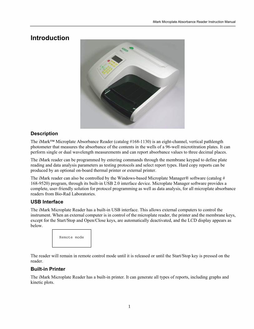
iMark Microplate Absorbance Reader Instruction Manual
2
Catalog Description 168-1130 iMark Microplate Absorbance Reader with built-in printer 168-1135 iMark Microplate Absorbance Reader with built-in printer
including Microplate Manager 6 software 168-6940 Checkmark Absorbance Reader Performance Validation Kit Accessories Catalog Description 168-1011 405 nm filter 168-1013 415 nm filter 168-1020 450 nm filter 168-1028 490 nm filter 168-1038 540 nm filter 168-1040 550 nm filter 168-1044 570 nm filter 168-1049 595 nm filter 168-1054 620 nm filter 168-1056 630 nm filter 168-1061 655 nm filter 168-1080 750 nm filter 168-1006 Replacement lamp for iMark Microplate Absorbance Reader 168-2007 Replacement printer paper package contains 3 rolls Custom filters between 400 and 750 nm may be ordered Corresponding catalog numbers can be found on wwwbio-radcom or you can order by specifying the wavelength and the model number of the reader
Checkmark Absorbance Reader Performance Validation Kit (catalog item 168-6940) consists of a plate with absorbance standards and software to calculate the accuracy and precision of the iMark Microplate Absorbance Reader
iMark Microplate Absorbance Reader Instruction Manual
3
External Features
Release latch for rear cover Rear cover
Printer slot Power button
Liquid crystal display (LCD)
Keypad
Reading chamber door
Power cord receptacle Serial number label
Cooling vents and fan
USB 20 interface
iMark Microplate Absorbance Reader Instruction Manual
4
Keypad Guide Main Returns to MAIN SCREEN StartStop Initiates plate reading using current active protocol Stops plate reading and printing Paper Feed Advances paper strip in internal printer Print Prints out the plate data and protocol information Edit Enters the Edit Menu and sets up the instrument Memory Recall Reads out protocol and plate data OpenClose Opens or closes the reading chamber door Up Arrow Moves the cursor upward Selects the alphabet or the symbol Left Arrow Returns to the previous screen Moves the cursor to the left Down Arrow Moves the cursor downward Selects the alphabet or the symbol Right Arrow Moves the cursor to the right Changes or selects the value and type Enter Completes or seals a field entry
DotFunction Inputs the dot Changes the input mode Ten Keys Inputs numbers or well type in plate mapping
0 EMP Empty 5 QC QC control 1 SMP Sample 6 CAL Calibrator 2 BLK Blank 7 CP Positive Control 3 STD Standard 8 CN Negative Control 4 CO Cutoff control 9 CW Weak Positive Control
OpenClose Edit
Print Paper Feed Main
START
STOP
Memory Recall
7 CP
8CN
9CW
4 CO
5QC
6CAL
2BLK
3STD
0 EMP
0FUNC
SMP
1
Change
ENTER
Back
Z = A gt
A = Z gt + minusbullbull
iMark Microplate Absorbance Reader Instruction Manual
5
Instrument Setup Unpacking the Instrument The shipping carton contains the following items
bull iMarktrade Microplate Reader with 415 nm 450 nm 490 nm 595 nm 655 nm and 750 nm interference filters installed on the filter wheel
bull Power cord
bull USB cable
bull Dust cover
bull Instruction manual
bull Warranty card
bull One roll of thermal printer paper
Inspect the exterior of the instrument for any signs of shipping damage Contact your local Bio-Rad representative if any of these items are damaged or missing
Initial Instrument Startup 1 Place the instrument on a clean sturdy table or bench It is important to keep the instrument in a clean
relatively dust free environment to ensure optimal performance
2 Connect the power cord to the back of the instrument Before connecting the instrument to the main electrical supply check that the AC voltage is appropriate for the instrument
3 To turn the power on press the green power button on the top of the instrument The LCD will display the version number of the on-board firmware After about three seconds the instrument will perform an initial self-diagnosis that requires about fifteen seconds The login screen displays for you to choose your user level (administrator or common user) and enter the password (initial password 00000) Please allow three minutes for the instrument to warm up (reach thermal equilibrium) before reading plates
Change password Select ldquoChange Passwordrdquo in the Security Menu
Enter the current Password then move the cursor to the 3rd line and enter a new password Press Enter to complete the field entry The system will return to the previous Security Menu
Change user mode Select ldquoChange userrdquo in the Security Menu
Select a desired user mode by pressing the Right Arrow key Enter the appropriate password for the selected user mode Press Enter to complete the field entry The system will return to the previous Security Menu
System Login User Administrator Password Press ENTER
iMark Microplate Absorbance Reader Instruction Manual
6
4 Install the printer paper The thermal printer paper is printable on one side only and must be properly installed for the printer to function The outside of the roll is the printable side
a Open the rear cover of the instrument b Tear off a small piece at the beginning of a new roll at an angle to form
a point c Place the roll of paper in the small pan-like holder positioned below
the printer The roll should be positioned so that it will feed from the bottom
d While pressing the PAPER FEED key feed the pointed end of the paper into the paper feed slot in the underside of the printer until the printer grabs the paper and feeds it through the slot in the top of the instrument
e Securely close the rear compartment
Multi-language support The iMark LCD can produce text in three languages English Russian and Chinese To switch to English from Russian or Chinese press the Main button then the Edit button to get to the configuration screen Press the downward-pointing arrow on the key pad six times to navigate to the language options line Press Enter twice to select English and then press Enter a third time to shut down the reader When restarted the iMark will display in English
Instrument Shutdown To shut down the instrument press the green power button on the top of the instrument for a few seconds Then the LCD will display a Power off Yes or No screen Select ldquoYesrdquo to shut down the instrument
Power off gtgtYes No
iMark Microplate Absorbance Reader Instruction Manual
7
Software Overview Capabilities The iMark Microplate Reader has on-board software that allows the user to set the plate reading and data analysis conditions to save these settings as a test protocol to read a microplate under this protocol and to print reports from the built-in printer The software communicates through the 4-line 20-character LCD and is controlled through the instruments membrane keypad
The software has three different protocol types End-point analysis Kinetic analysis and Checkmark validation The Checkmark validation function is used only by the administrator to verify quality control
The display shows the current mode The user can choose between these protocol types or can press the Memory Recall key to use the current protocol type
Quick Guide to Reading a Plate 1 Turn on the instrument Allow about 30 seconds for self-diagnosis The instrument needs to warm up for
about three minutes prior to reading a plate
2 Upon power up the login screen will appear Enter the login password (initial password 00000) press Enter
3 Program a protocol for your assay See page 22 for information on Editing a Kinetic protocol or page 25 for Editing an End Point Protocol Make sure filters installed correlate with information entered in reader firmware
4 Select the protocol of choice if programmed See the Memory Recall section on page 21 for detailed operation
5 Review or print parameters set in the protocol See the Editing End Point Protocol section on page 25 for details
6 Verify settings on Cutoff Report Limit STDs Mode Mapping and kit name parameters are as desired
7 Protocol setting can be printed see the Printing Reports and Protocols section on page 20 for information
8 All reports other than the raw data report require plate mapping Set the plate map with instructions from the Plate Map Setting Procedure section on page 33
9 The Matrix and Limit reports require assignment of upper and lower limits Set the upper and lower limits in the Editing End Point Protocol Limit setting window
10 The Cutoff report requires definition of the cutoff setting Refer to the Cutoff Setting Procedure section on page 26
11 The Curve fit and Concentration reports require that standard concentration and locations must be defined Refer to page 29 for details on how to define the standards and the curve fit parameters
12 Set the general reading mode (single or dual wavelength reading plate shaking read mode) following the instructions in the Mode Setting Procedure section on page 32
After warm-up is complete
13 Press the ldquoMainrdquo key The main screen appears on the LCD
14 Carefully place the microplate in the reading chamber Press the ldquoStartStoprdquo key to read
iMark Microplate Absorbance Reader Instruction Manual
8
Instrument Functions Calculations The Microplate Reader uses Beers Law to calculate the absorbance value of each well Beers Law states that absorbance is equal to the log10 of the ratio of the baseline measurement intensity (Io) to the sample measurement intensity (I)
Beers Law Absorbance = Log10 (IoI)
Before measuring the plate the reader takes a reading for all eight photodiode channels These values are recorded as the baseline measurement (Io) values for each channel respectively The reader then records the sample measurement (I) value for each well and calculates the absorbance using these values Channel-to-channel error is significantly reduced because the Io value for a given channel is used only in determining the absorbance of the wells of that channel
Security password The iMark Microplate Reader requires a user login with password This security feature helps to prevent any unwarranted modifications to the analysis conditionsprotocols and data stored in the instrument and identifies the operator on reports The reader has two user settings the Administrator and the Common user Each user level has its own security password
Memory Back-Up The battery back-up provides memory even after the reader is turned off
The following information will be saved in the memory until new reading parameters are set by the user or a new plate is read by the instrument Note that if a run is aborted before it is finished all the previous plate reading data remain in memory and none of the data from the aborted reading is stored
bull The ten latest sets of End-point protocol plate reading results
bull The two latest sets of Kinetic plate reading results (max 30 series of readings for each Kinetic Protocol)
bull 64 End-point Protocol settings and 2 Kinetic Protocol settings
bull A set of Checkmark reference data and the one latest set of Checkmark reading result
bull A set of standard curve data for the storage of standard curves and graphs
bull Eight wavelength values for filters
bull Laboratory name
bull Two security passwords (for the Administrator and the Common user)
bull Instrument serial number
In addition to the battery back-up memory the instrument has a small amount of non-volatile memory to keep the system information after the battery is dead The serial number is stored in this memory The average battery life is 5 years
iMark Microplate Absorbance Reader Instruction Manual
9
The first time the instrument is turned on or after a battery failure the following default information is held in the memory
1 Both Administrator and Common user security passwords are set to 00000
2 Laboratory name is Bio-Rad Laboratories
3 All wavelength values of the filters are set to --- nm
4 The date and time of the calendar chip are set to 1 day 1 month 00 year 0 hour and 0 minute
5 No plate reading data is available
6 End-point protocol is chosen and the protocol number is set to 1
7 No standard curve data for the storage of standard curves and graphs is available
Limits The Microplate Reader displays absorbance readings with absolute values as 3500 Out-of-range absorbance values (those with absolute values greater than 3500) are displayed as either or - For example if the absorbance is 4500 then the display will read and if the absorbance is -4500 the display will read -
iMark Microplate Absorbance Reader Instruction Manual
10
Report Types Two types of reports can be generated End-point protocol and Kinetic protocol Each of these and their subtypes are described below After these descriptions there are flow diagrams that show how to access specific choices
End-point Protocol Reports Nine types of End-Point Protocol reports can be generated raw data absorbance limit matrix cutoff curve fit concentration difference and TeSeE screening reports
1 Raw data report The Raw data report is the uncorrected absorbance values (without blank subtraction) In single-wavelength mode the reported value is the measured absorbance In dual-wavelength mode the reported value is the difference between the uncorrected readings taken with the measurement filter and with the reference filter
2 Absorbance report The Absorbance report is the blank-corrected absorbance values The mean absorbance value of all of the wells designated as assay blanks is calculated and then subtracted from all 96 values of the raw data set to produce the Absorbance report
Abs = Raw ndash Blank mean
Blank mean = Xn
SD = [X^2 ndash n(Blank mean)^2n-1]^12
Where
SD = Standard deviation
X = Sum total of the raw absorbance for each blank
X^2 = Sum total of the squared raw absorbance for each blank
n = Number of blanks
3 Limit report The Limit report provides a qualitative YESNO report Wells with blank-subtracted absorbance values between the upper and lower limits are represented with an asterisk () wells with absorbance values below the lower limit by minus signs (-) and wells with absorbance values greater than the upper limit by positive signs (+)
4 Matrix report The Matrix report provides a qualitative report of the relative magnitude of the absorbance values on the plate The absorbance range defined by the upper and lower limits is divided into 10 equal partitions numbered 0 through 9 The blank-subtracted absorbance value of each well is classified according to the partition of the matrix to which it corresponds and is reported as a signal digit Wells with absorbance values greater than the upper limit are reported by plus signs (+) and wells with absorbance values less than the lower limit by minus signs (-)
iMark Microplate Absorbance Reader Instruction Manual
11
5 Cutoff report The Cutoff report provides a qualitative report of the relative magnitude of the absorbance values or converted concentrations on the plate
Four types of cutoff reports are supported ranged constant single constant formula and ratio These and their subtypes are listed below
a Ranged Constant The user inputs Positive and Negative values to be used as the cutoff
For units designated Abs if the absorbance of a well is within the positive and negative cutoff values the well is scored If the absorbance of a well is greater than the positive value the well is scored + and if the absorbance of a well is below the negative value the well is scored -
For units not designated Abs the absorbance value of each well is converted to the concentration value using the curve fit constants of the curve fit report If the concentration of a well is within the positive and negative cutoff values the well is scored If the concentration of a well is greater than the positive value the well is scored + and if the concentration of a well is below the negative value the well is scored -
b Single Constant The user inputs Positive and Gray zone values to be used as the cutoff
For units designated Abs if the absorbance of a well is within the gray zone value of the positive cutoff value the well is scored If the absorbance of a well is more than the gray zone value and greater than the positive value the well is scored + and if the absorbance of a well is more than the gray zone value below the positive value the well is scored -
Upper cutoff absorbance = Positive absorbance + ((Gray zone100) Positive absorbance)
Lower cutoff absorbance = Positive absorbance ndash ((Gray zone100) Positive absorbance)
For units not designated Abs the absorbance value of each well is converted to the concentration value using the curve fit constants of the curve fit report If the concentration of a well is within the gray zone value of the positive cutoff value the well is scored If the concentration of a well is more than the gray zone value greater than the positive value the well is scored + and if the concentration of a well is more than the gray zone value below the positive value the well is scored -
Upper cutoff conc = Conc of positive controls + ((Gray zone100) Conc of positive controls)
Lower cutoff conc = Conc of positive controls - ((Gray zone100) Conc of positive controls)
c Formula The mean absorbance values of the Positive and Negative wells defined in the plate map are used for the cutoff formula calculation
The 12 types of formula-based cutoff reports are
i k CNx vii k + CNx
ii k CPx viii k + CPx
iii k COx ix k + COx
iv CNx k x kCNx + CPx
v CPx k xi xi (CNx + CPx) k
vi COx k xii k1CNx + k2CPx
iMark Microplate Absorbance Reader Instruction Manual
12
The result absorbance value of the formula calculation and the gray zone value that is entered by the user are used for the cutoff
The upper and lower cutoff values are
Upper cutoff absorbance = Result of a Formula + ((Gray zone100) Result of a Formula)
Lower cutoff absorbance = Result of a Formula - ((Gray zone100) Result of a Formula)
The absorbance range of the upper and lower cutoff is divided into 10 equal partitions numbered 0 through 9 The absorbance value of each well is classified according to the partition of the matrix to which it corresponds and is reported as a signal digit Wells with absorbance values greater than the upper cutoff are reported by plus signs (+) and wells with absorbance values less than the lower cutoff by minus signs (-)
d Ratio The mean absorbance value of the Calibrator wells defined in the plate map and the concentration value entered by the user are used for the cutoff ratio Before the cutoff the absorbance value of each well is converted into the concentration value The ratio of ConcentrationAbsorbance of Calibrator is applied to the conversion Then the cutoff is done with the defined Positive and Negative or the defined Positive and Gray zone values
6 Curve Fit Report The Curve fit report provides a regression analysis based on the absorbance values of a series of standards There are ten types of curve fits supported with the onboard software on iMark Microplate readers
i 5P Logistic Rodbard ii 4P Logistic Rodbard iii 5P Logistic Cook-Wilkenson iv 4P Logistic Cook-Wilkenson v 5P Exponential vi Sigmoid Logistic vii Linear regression viii Quadratic regression ix Cubic x Point-To-Point regression
The onboard software calculates the best fit of the defined curve between each set of two consecutive data points in the standard curve of absorbance vs concentration And then it generates the report with the coefficients of regression the correlation coefficient and the standard error
For readers with the optional internal printer or with an external ESCP printer which accepts ESCP code a graph of the standard curve may be generated when selected in the report parameter
7 Concentration Report In case of the curve fit the Concentration report also provides the regression analysis After the calculation of the curve fit it calculates the concentrations values of the samples and generates the report
In case of the cutoff constant with the unit not designated Abs and in case of the cutoff ratio the reader generates the list of concentration of each well
8 Difference Report The Difference report is the subtraction report between the neighboring columns or row
iMark Microplate Absorbance Reader Instruction Manual
13
9 TeSeE Screening Report Analysis of the TeSeE screening assay results can be done with two pre-programmed protocols ldquoTeSeErdquo protocol is stored in Endpoint Protocol position 5 and ldquoTeSeE eqrdquo is stored in Endpoint Protocol position 6 as factory default setting Both protocols are locked
TeSeE screening report is generated only if these protocols are selected as current active protocol Plate is first validated according to negative and positive controls validation criteria samples are then compared to the calculated cut-off
Criteria for plate validation are set as follows
Criteria 1 Individual Negative Control must be lt 0150
Number of valid Negative Control must be gt= 3
Criteria 2 Individual Negative Control must be lt 1400 Negative Control average
Number of valid Negative Control must be gt= 2
Criteria 3 Positive Control average must be gt= 1000
Cutoff is calculated as follows
TeSeE
Positive cutoff = Negative Control average + 0210
Negative cutoff = (Negative Control average + 0210) 0900
TeSeE eq
Positive cutoff = Negative Control average + 0210
Negative cutoff = Negative Control average + 0090
Samples are interpreted as follows
ldquoPOSrdquo Positive when sample OD gt= Positive cutoff
ldquoNEGrdquo Negative when sample OD lt Negative cutoff
ldquordquo Gray zone NEG cutoff =lt sample OD lt POS cutoff
iMark Microplate Absorbance Reader Instruction Manual
14
Protocol
Security
Filters
Date Set
Lab name
Cutoff
Report
Limit
STDs
Mode
Mapping
Kit name
Not Used
Constant
Control
Formula
Ratio
Ranged Cutoff Single Cutoff
Ranged Cutoff Single Cutoff
12 choices of cutoff formula
Concentration
Unit
Cutoff value
Cutoff Values setting Gray zone setting when single cutoff
Cutoff Control setting Gray zone setting when single cutoff
Coefficient setting of selected formula
0 - 9999
17 choices of unit
Cutoff Values setting Gray zone setting when single Cutoff
Ranged Cutoff Single Cutoff
Raw(Raw data) Abs(Absorbance) Lim(Limit) Mtx(Matrix) Cut(Cutoff) Crv(Curve fit) Cnc(Concentration) Dif(Difference)
Upper Limit Lower Limit For Limit Report
Standard information
Curvefit
Number of STD Concentration
Unit
Curvefit type Graph axis
Set Photo mode Set Shaking
Set Read mode
Manual mapping
Automatic mapping
Change password
Change user
End-point Analysis Protocol
Up to 12 Standards 0 to 9999 17 choices
12 choices of curve fit type 4 choices of graph axis combination of Log and Linear
SingleDual Wavelength Shake (Yes No) Speed (High Low Mid) Time Read Speed (FastStep) and Read Mode (NormalEval)
Func key to switch [N] to [F] [N] for sample number [F] for sample
Func key to switch from [ABC] to [abc] to [sym] key to move cursor
For current user mode Administrator or common user Administrator has power to switch
Filter wavelength setting for 1-8 positions ldquo0rdquo for no filter
DayMonthYear HourMin
Func key to switch from [ABC] to [abc] to [sym] key to move cursor
Save STDC
Language
Save STD Curve
Rename STD Curve
Select Language
5 choices of storage number
5 choices of STD curve
Func key to switch from [ABC] to [abc] to [sym] key to move cursor
Choices of pre-installed language for LCD and report printout
BlankCNCWCPCOQCCalibratorSampleReplicate well
Recall Setting Select STD Curv
Recall YesNo Selection 5 choices of memorized STD curve
Edit
Bold for menu pages
LCD adj and key to change contrast
Italic for program pages
iMark Microplate Absorbance Reader Instruction Manual
15
Kinetic Protocol Reports Four types of Kinetic protocol reports can be generated absorbance kinetic plots linear regression and GALT reports
1 Absorbance Report The Kinetic Absorbance report is the series of absorbance data in the kinetic sequence
2 Kinetic Plots Report The Kinetic plots are the absorbance plots of each well in the plate It is available for readers with the optional internal printer or with an external ESCP printer which accepts ESCP code
3 Linear Regression Report The Linear Regression report provides the calculation of Kinetic reaction rate for each well using the linear regression
4 GALT Report The GALT report calculates the following formula for each well between two readings of a plate
GALT = (R2 ndash R1) k
Where R1 = Absorbance value of 1st reading
R2 = Absorbance value of 2nd reading
k = GALT factor
iMark Microplate Absorbance Reader Instruction Manual
16
Func key to switch from [ABC] to [abc] to [sym] key to move cursor
Func key to switch from [ABC] to [abc] to [sym] key to move cursor
Func key to switch from [ABC] to [abc] to [sym] key to move cursor
DayMonthYear HourMin
Filter wavelength setting for 1-8 positions ldquo0rdquo for no filter
Edit
Kinetic Analysis Protocol
Protocol
Security
Filters
Date Set
Lab Name
Change password
Change user
LockUnlock
Mode
Report
Calc
Mapping
Assay
Kit name
Reading Inter
Shaking Phmode
Speed
Number of reads (2-30) start delay time (0-999) Reading interval time Shake (FirstEverydisable) Speed (High Low Mid) Time Single Dual wavelength Read Speed (FastStep)
CC Limit (correlation coefficient limit) Calcrange (calculation range of reading number) for Linear regression Report
GALT factor k input (0- 9999) Result = (2nd read ndash 1st read)k for GALT Report
Manual mapping
Automatic mapping
Func key to switch [N] to [F] [N] for sample number [F] for sample type
General Kinetic or GALT assay assay type selection
Absorbance KINETIC Plots Linear regression when General Kinetic Assay selected GALT report when GALT Kinetic assay selected
For current user mode Administrator or Common user Administrator has power to switch
Special Buttons
Memory Recall
Main
Protocol Plate Data
Report Protocol
End point Kinetic
Checkmark
1-64 End point protocol storage 1-2 Kinetic protocol storage Checkmark reader test
Printout
Returns to MAIN screen
SaveSTDC
Language
BlankCNCWCPCOQCCalibratorSampleReplicate well
Save STD Curve
Rename STD Curve
Select Language
5 choices of storage number
5 choices of STD curve
Choices of pre-installed language for LCD and report printout
Bold for menu pages
LCD adj and key to change contrast
Italic for program pages
iMark Microplate Absorbance Reader Instruction Manual
17
Screen by Screen Procedures Initial Startup
01Kinetic-1 M405(1)R605(6)30read Shake999sMidEvery 382402 180901
End point mode
Kinetic mode
Self-diagnosis iMark Microplate Reader 1305 180901
System Login User Administrator Password Press ENTER
Login SCREEN
01EndPoint Assay01 M405(1)R655(6) Shake999sMid 382402 180901
Checkmark Validation Program
180901
Checkmark mode
Initializing reader
MAIN SCREEN
Self-Diagnosis This screen will appear upon power-up and during self-diagnosis Date and time are also indicated on this screen
Initialization After self-diagnosis the system initializes all the hardware
Security Check The system requires a password to confirm that the user is the authorized operator Pressing the ChangeRight arrow key will switch the user mode between Common user and Administrator Password for both Common user and Administrator is set as ldquo00000rdquo upon factory shipment Operator can change the password in the EDIT menu See Security
System Ready When this MAIN screen is on the LCD the StartStop key can be pressed for microplate reading Pressing StartStop key will begin reading with the current protocol There are three kinds of MAIN screens depending on the current protocol type Endpoint Kinetic and Checkmark program The four arrow keys Numeral keys Main key and Enter key are inactive StartStop Memory Recall Edit Print and Paper Feed keys are active
01EndPoint Assay01 M405(1)R655(6) Shake999sMid
180901
Kit name for current active protocol
01Kinetic-1 M405(1)R605(6)30read Shake999sMidEvery 382402 180901
Kinetic M Measurement wavelength and its position in the filter disk R Reference wavelength and its position in the filter disk Number of reading for KINETIC
Storage number in memory of current active protocol
Plate shaking parameters period in seconds and speed
M Measurement wavelength and its position in the filter disk R Reference wavelength and its position in the filter disk
Date (day month year)
Plate shaking parameters Period in seconds Speed (fast middle slow) Mode (before every read before first read and no shake)
End point
iMark Microplate Absorbance Reader Instruction Manual
18
Configuring the System NOTE To return to the previous screen use the backleft arrow key
Edit Menu
Security function raquoChange Password bullChange user bullLockUnlock Prtl
Change Password
LockUnlock
Change user
Change Password Current New Common user
Security for current active Protocol [Lock] Unlock
System Login User Administrator Password Press ENTER
Change Password Select ldquoChange Passwordrdquo in the Security Menu Enter the current password then move the cursor to the 3rd line and enter a new password Press Enter to complete the field entry The system will return to the previous Security Menu Change User Mode Select ldquoChange userrdquo in the Security Menu Select a desired user mode by pressing the Right Arrow key Enter the appropriate Password for the selected user mode Press Enter to complete the field entry The system will return to the previous Security Menu LockUnlock Protocol Select ldquoLockUnlock Prtlrdquo in the Security Menu Move the selected mark ldquo[ ]rdquo to the desired position Lock or Unlock using the Right Arrow key Press Enter to complete the field entry The system will return to the previous Security Menu If ldquoLockrdquo is selected the current active protocol will be protected against modification made by a Common user If ldquoUnlockrdquo is selected the current active protocol can be modified by any user mode NOTE Only the Administrator has authority to lock and unlock the Checkmark Protocol
Edit Menu This menu can be accessed by pressing the Edit key in the MAIN SCREEN
Security Menu Security Setting Select ldquoSecurityrdquo in the Edit Menu screen and press Enter The Security Menu appears on the screen
raquoProtocol Labname Security SaveSTDC Filters Language Date set LCD adj
iMark Microplate Absorbance Reader Instruction Manual
19
1400nm 5650nm 2450nm 6nm 3475nm 7nm 4650nm 8nm
Filter
DayMonthYear 16 05 01 Hour Minutes 18 55
Date set
Enter Lab name Bio Rad Laboratories uarr [ABC]
Lab name
Filter Setting Move the cursor to the desired position by using the Up Down and Right arrow keys Enter the filter wavelength on the selected position using the number keys If the selected position of the filter disk is empty enter three ldquordquo Press Enter to complete the field entry The system will return to the previous Edit Menu screen
Calendar Setting Move the cursor to the desirable position for date or time input by using the Up Down and Right arrow keys Enter the present date or time using the number keys Press Enter to complete the field entry The system will return to the previous Edit Menu screen
Lab Name Setting Use the Up and Down arrow keys to select from ldquoArdquo to ldquoZrdquo and symbols Use the Number keys for numeric input Use the Right arrow key to move the cursor to the right Use the Left arrow key to return the cursor to the Edit Menu screen Pressing the FUNCrdquo key will toggle the character mode between Upper case alphabet Lower case alphabet and symbol The current character mode is indicated on the lower right corner of the LCD
Save STD Curve gt Save STD Curve Rename STD Curve
Save STDC Save STDC Setting Select ldquoSave STDCrdquo in Edit Menu screen above and press Enter The Save STD Curve Menu appears on the screen Move the cursor to the desired position by using the Up and Down arrow keys
Select STD storage gt 1120304 1500 2 3150304 1030
Select for renaming gt 1160304 1125 2 3150304 1030
Save STD Curve To save a STD Curve select the storage number between 1 and 5 Use the Up and Down arrow keys to move the cursor to the desired storage number and press Enter to complete the selection After the storage number selection the rdquoAre you surerdquo message appears Select ldquoYesrdquo or ldquoNordquo and press Enter In case of ldquoYesrdquo the reader saves the STD Curve and returns to the Edit Menu screen If the curve fit calculation is not done or has not finished successfully an error message will appear and the STD Curve will not be saved STD curve does not
exist yet Press any key
Save STD Curve 1160304 1125 Are you sure gt Yes No
Rename STD Curve To change a name of an STD Curve select a storage number between 1 and 5 Use the Up and Down arrow keys to move the cursor to the desired storage number and press Enter to complete the selection Use the Up and Down arrow keys to select from ldquoArdquo to ldquoZrdquo and symbol Use the Number keys for numeric input Use the Right arrow key to move the cursor to the right Use the Left arrow key to return the cursor to the Edit Menu screen Pressing the FUNCrdquo key will toggle the character mode between Upper case alphabet Lower case alphabet and symbol The current character mode is indicated on the lower right corner of the LCD
1160304 1125 gtSTD Curve 1 lt
[ABC]
Save STD Curve
Rename STD Curve
iMark Microplate Absorbance Reader Instruction Manual
20
Printing Reports and Protocol information
Print menu raquoReports bullProtocol
Print Menu Print Menu Access this menu screen by pressing the Print key in the MAIN screen Printing Reports Select ldquoReportsrdquo and press Enter to print the current active plate data report Printing Protocol Information Select ldquoProtocolrdquo and press Enter to print all parameter settings in the current active protocol Stop Printing Press the StartStop key during printing to stop the print job immediately When printing is completed the system automatically returns to the MAIN screen
Select Language raquoEnglish bull bull bull
Language Changing Language Select a desired language using the Up and Down arrow keys and press Enter to complete the selection The system will generate a message for an immediate power off to restart Select ldquoYesrdquo and press Enter to activate the selected new language The newly-changed language will be applied to the LCD screen and printed reports Power off
gtgtYes No
LCD Contrast 12345678901234567890
laquo 26 raquo ENTER to complete
Adjusting LCD Contrast Adjust LCD contrast by using the Right and Left arrow keys and press Enter to complete the adjustment
LCD adj
iMark Microplate Absorbance Reader Instruction Manual
21
Memory Recall Operation
01 200500 1400 02raquo210500 1700 03 200500 1800 darr04raquo200500 1900
01raquo200500 0900 02raquo200500 1000
Memory Recall raquoProtocol bullPlate Data
Protocol type menu
Data type menu
End Point
Kinetic
End Point
Kinetic
Memory Recall Menu
Select protocol type raquoEnd Point
bullKinetic bullCheckmark
Select Protocol 02 uarrraquo Protocol -2 Protocol -3 darr Protocol -4
Select Protocol 01 raquo Kinetic -1 GALT
Select data type raquoEnd Point
bullKinetic bullCheckmark
200501 0900
Checkmark
Checkmark program has been activated Press any key
Checkmark
Selecting Protocol Move the cursor to the position of the desired protocol and press Enter to complete the selection NOTE ldquordquo indicates the currently activated protocol and ldquordquo indicates a security locked protocol There is no protocol selection with ldquoCheckmarkrdquo When a protocol is selected the system will then automatically return to the MAIN screen
Changing Current Active Protocol Select ldquoProtocolrdquo in Memory Recall menu above and press Enter The Select Protocol type menu will appear on the screen Select a protocol using the Up and Down arrow keys Press Enter to complete the selection
Selecting Plate Data Move the cursor to the position of the desired plate data and press Enter to complete the selection NOTE ldquordquo indicates the currently activated plate data There is only one storage for ldquoCheckmarkrdquo data When plate data is selected the system automatically returns to the MAIN screen
Changing Current Active Plate Data Select ldquoPlate Datardquo using the Memory Recall button and press Enter The Data type menu will appear Use the Up and Down arrow keys to select a plate data type Press Enter to complete the selection
This menu screen can be accessed by pressing the Memory Recall key in the MAIN screen
iMark Microplate Absorbance Reader Instruction Manual
22
Editing the Kinetic Protocol
Select ldquoProtocolrdquo in the Edit Menu and press Enter The Kinetic Protocol menu will appear on the screen if the current active protocol type is Kinetic
Reading speed [Fast mode] Step mode
Speed
raquoReading Speed Inter Shaking Phmode
Kinetic Mode
Kinetic Protocol Menu
raquoMode Report Calc Kit name Mapping Assay
This menu screen can be accessed by selecting ldquoModerdquo in the Kinetic Protocol menu above
Number of Reading = 20 (2-30) Start Delay time = 25 sec(0-999)
Reading
Number of Reading = 2 Start Delay time = 25 sec(0-999)
Number of Readings and Start Delay Time Setting Press the Up or Down arrow key to change the number Enter the appropriate numbers with the numeral keys and press Enter to complete the field entry The system will return to the Kinetic Edit Menu If GALT is the current assay type the number of reading fields is fixed at 2 Press the StartStop key to set the Start Delay time enter a value and press Enter until the reading starts
1-gt2raquo 100 sec 2-gt3 100 sec 3-gt4 100 sec darr4-gt5 100 sec
Inter Use same interval between all reads
raquoYes No
Setting Reading Intervals The system prompts the operator to set a reading interval before each plate run Move the cursor to the desired selection ldquoYesrdquo or ldquoNordquo and press Enter The system generates the interval entry screen Move to the active entry field by pressing the Up and Down arrow keys and enter appropriate numbers using numeral keys Press Enter to complete all field entries The system will return to the Kinetic Mode menu
Photometric Dual Measurement405 nm Reference 655 nm
Ph mode Photometric Mode Setting When the ldquoPhotometricrdquo field is activated pressing the Right arrow key will switch the field entry ldquoSinglerdquo lt-gtrdquoDualrdquo Pressing the Up or Down arrow keys will move the cursor to the next entry field Pressing the Right arrow key when the wavelength field is activated will change the wavelength to the next available selection installed in the reader Press Enter to complete all field entries
Shaking parameters Before Every read Speed Mid Time 999 sec
Shaking Plate Shake Parameters When the ldquoBeforerdquo field is activated pressing the Right arrow key will change the field entry ldquoEveryrdquo-gtrdquo--rdquo-gtrdquoFirstrdquo-gt When the ldquoSpeedrdquo field is activated pressing the Right arrow key will change the field entry ldquoMidrdquo -gtrdquoHirdquo-gtrdquoLowrdquo-gt When the ldquoTimerdquo field is activated enter the time value for plate shaking period using the numeral keys Press Enter to complete all field entries
Selecting Reading Speed Use the Up or Down arrow keys to switch the selection Press Enter to complete the selection
Edit Menu raquoProtocol Labname Security bullSaveSTDC Filters bullPrinter Date set
This menu screen can be accessed by pressing the Edit key in the MAIN screen
iMark Microplate Absorbance Reader Instruction Manual
23
Kit name for 01 raquoGAP TEST IgGlaquo uarr [ABC]
Kit name
Calculation
Mapping
Assay
Assay type selection raquo[General KINETIC] GALT assay
Calculation Param CC Limit 0910
Calcrange 10 - 20
Select Mapping mode raquoManual mapping bullAutomatic mapping
raquo[Linregression] bullAbsorbance bullKINETIC Plots
Report
Plate Mapping See Plate Map setting procedure
Result = (R2 ndash R1)k k = 999999 R11st Reading R22nd Reading
If GALT
Setting the Kit Name Use the Up and Down arrow keys to select alphabet from ldquoArdquo to ldquoZrdquo and space Use the Number keys for numeric input Use the Right arrow key to move the cursor to the right Use the Left arrow key to return to the Protocol Menu screen Pressing ldquoFUNCrdquo key will change the character mode Upper case alphabet -gt Lower case alphabet -gt symbol The current character mode is indicated on the lower right corner of the LCD
Kinetic Protocol Menu
Selecting Kinetic Assay Type Move the cursor to the desired Assay type by pressing the Up or Down arrow keys Press Enter to complete the selection The item with mark ldquo[ ]rdquo is the currently selected item GALT assay Result = factor x (2nd Read ndash 1st Read)
Selecting Report Type Move the cursor to the desired report type by pressing the Up or Down arrow keys Pressing the Right arrow key will select or deselect the item Press Enter to complete the selection Note When GALT assay is selected ldquoGALT reportrdquo shall be the only one option on this screen
raquoMode bullReport bullCalc bullKit name bullMapping bullAssay
Calculation Parameter Setting When the ldquoCC Limitrdquo field is activated pressing the numeral key will enter the desired numbers Press Enter to complete all field entries If the GALT Reports is activated pressing the numeral keys will enter the desired numbers Press Enter to complete all field entries
iMark Microplate Absorbance Reader Instruction Manual
24
Checkmark Value Setting (Administrator only)
raquoSerial Report bullLinearity ref bullMaxCV bullFilter Check ref
Checkmark Protocol Menu
raquoSerial 0000 Reptype Simple
405nm S10158 Linearity S20309 reference S31401 S42109
MaxCV raquoS115 Linearity S205 reference S302 S402
Filter max min 4051875 0329 4501167 0954 darr 4920596 0103
Serial Report
Linearity reference
Max CV
Filter check reference
Filter max min uarr 5401875 0329 6201167 0954 6900596 0103
Setting the Serial Number and Report Type Pressing the Up and Down arrow keys will move the cursor and change the field entry When ldquoSerial rdquo field is active enter the serial number that will be shown in the data sheet of the Checkmark plate using the numeral keys When the ldquoRep typerdquo field is active pressing the Right arrow key will switch the report type between ldquoSimplerdquo and ldquoFullrdquo
Setting the Linearity Reference Value Pressing the Up or Down arrow keys will move the field entry from S1 to S4 Pressing the Right arrow key will change the wavelength 405 nm-gt450 nm-gt492 nm-gt540 nm-gt620 nm-gt690 nm Use the numeral keys for the reference value setting Pressing Enter will complete all field entries at all wavelength
Max CV setting Pressing the Up or Down arrow keys will move the field entry from S1 to S4 Use the numeral keys for the Max CV setting Press Enter to complete all field entries
Setting the Filter Check Reference Value Initial screen shows the reference entries for 405 nm to 492 nm and pressing the Down arrow key at the bottom of the screen entries will scroll to the next page for 540 nm to 690 nm Pressing the Up Down and Right arrow keys will move the field entry Use the numeral keys for the filter check reference value setting Press Enter to complete all field entries
Select ldquoProtocolrdquo in the Edit Menu and press Enter The Checkmark Protocol Menu will appear on the screen if the current active protocol type is Checkmark mode
Edit Menu raquoProtocol bullLabname bullSecurity bullSaveSTDC bullFilters bullPrinter bullDate set
This menu screen can be accessed by pressing the Edit key in the MAIN screen
iMark Microplate Absorbance Reader Instruction Manual
25
Editing End Point Protocol
Upper Limit= 2000 Lower Limit= 0000 input range 0ndash3500 Upper gt Lower
Standard menu raquoSTD information
bullCurvefit bullRecall STD Curve
raquoCutoff bullMode bullReport bullMapping bullLimit bullKit name bullSTDs
Cutoff
See Plate Map setting procedure
See Standard setting procedure
See Mode setting procedure
raquo[Not use] bullRatio bullConstant bullContrl bullFormula
raquoSet photo mode bullSet shaking bullSet read mode
Select mapping mode raquoManual mapping bullAutomatic mapping
Mapping
Mode
Report
STDs
Limit
Kit name for 01 raquoGAP TEST IgGlaquo uarr [ABC]
Kit name See Kit name setting in Editing Kinetic Protocol
See Cutoff setting procedure
Select ldquoProtocolrdquo in Edit Menu screen above and press Enter The End point Protocol Menu will appear on the screen if the current active protocol type is End point mode
End Point Protocol Menu
raquo[Raw] bullMtx bullCnc bullAbs bullCut bullDif bullLim bullCrv
If ldquoDifrdquo selected
[Raw] bullMtx bullCncbullAbs bullCut [Dif] bullLim bullCrv raquorow odd-even
Seting the Report Type Use the Up and Down Arrow key to move the cursor and press the Right Arrow key to select or deselect the report type Selected report type is marked as ldquo[ ]rdquo Press Enter to complete the selection
Setting the Limit Value Use the Up and Down Arrow key to move the cursor and enter the OD value using the numeral keys The OD value range is 0000 - 3500 Press Enter to complete the selection
Edit Menu raquoProtocol bullLabname bullSecurity bullSaveSTDC bullFilters bullPrinter bullDate set
This menu screen can be accessed by pressing the Edit key in the MAIN screen
iMark Microplate Absorbance Reader Instruction Manual
26
Cutoff Setting Procedure
Cutoff Setting Menu This menu is entered by choosing Cutoff in the End Point Protocol Menu It is used to set the cutoff type The cutoff type marked with ldquo[ ]rdquo is the current selection The Up and Down arrow keys move the cursor to the desired item in the menu list When the desired parameters have been selected press Enter twice to accept the selection and to continue to the next screen Not use means that the reader does not generate the cutoff report Four types of cutoff are supported
1 Cutoff Constant 2 Cutoff Control 3 Cutoff Formula 4 Cutoff Ratio
a Cutoff Constant
Selection of SingleRanged Cutoff Constant This menu selects Single or Ranged cutoff type The cutoff type marked with ldquo[ ]rdquo is the current selection The Enter key seals the selection and resumes to the next setting screen
Single Cutoff Constant The Numerical keys and the Decimal point key are used to enter the positive and gray zone values The Right arrow key is used to select the unit The Up and Down arrow keys move the cursor to the desired parameter of the single cutoff The Enter key sets all values and selection of the cutoff constant and returns the user to the previous screen Ranged Cutoff Constant The Numerical keys and the Decimal point key are used to enter the positive and negative values The Right arrow key is used to select the unit The Up and Down arrow key moves the cursor to the desired ranged cutoff parameters The Enter key sets all values and selection of the cutoff constant and returns to the previous screen NOTE Two available Cutoff constants are ldquoAbsorbancerdquo and ldquoConcentrationrdquo If Abs is chosen the Absorbance cutoff will be done with the cutoff constant parameters defined and the absorbance report is generated For other units defined in the curve fit setting the Concentration value using the curve fit and then cutoff is done with the cutoff constant parameters defined and the concentration value of each well It is necessary to set the curve fit parameters
raquoNot usex bullRatio [Const] bullContrl bullFormula
raquoPositive gt= 9999 Gray zone 50 Unit moll
raquoPositive gt= 9999 Negative lt 1999 NegativeltPositive Unit moll
raquoRanged cutoff [Single cutoff]
Single cutoff
Ranged
iMark Microplate Absorbance Reader Instruction Manual
27
b Cutoff Control
Selection of SingleRanged Cutoff Control This menu screen selects Single or Ranged cutoff type The cutoff type marked with ldquo[ ]rdquo is the current selection The Enter key seals the selection and resumes to the next setting screen
Single Cutoff Control The Numerical keys are used to enter the gray zone value The unit is fixed to Abs The Enter key sets the value of the cutoff control and returns to the previous screen Ranged Cutoff Control There is no parameter to set for the ranged cutoff control The Enter key returns to the previous screen NOTE CNx is the mean absorbance value of Negative control wells and CPx is the mean absorbance value of Positive control wells These wells are defined in the plate map setting The cutoff is done with the Positive and Negative value to the absorbance value of each well
c Cutoff Formula
Selection of Formula This menu screen selects a formula for cutoff calculation The formula marked with ldquo[ ]rdquo is the current selection The Up and Down arrow keys move the cursor to the desired formula type The movement of the cursor follows the scroll of this screen The Enter key marks the selection and advances the user to the next setting screen The supported formula types are
1 k CNx 2 k CPx 3 k COx 4 CNx k 5 CPx k 6 COx k 7 k + CNx 8 k + CPx 9 k + COx 10 kCNx + CPx 11 ( CNx + CPx ) k 12 k1CNx + k2CPx
Coefficient for Cutoff Formula 1 to 11 The Numerical keys and the Decimal point key are used to enter the coefficient k and gray zone values The Up and Down arrow key moves the cursor to the desired parameter of the cutoff formula The Enter key sets all values of the cutoff formula and returns to the previous screen
Positive gt= CNx Gray zone 50 Unit Abs
Positive gt= CPx Negative lt CNx Unit Abs
Enter key to accept
raquoRanged cutoff [Single cutoff]
Single cutoff
Ranged
Input coefficient k = 001 (001-10) Gray zone 50(0-99)
k CNx k CPx k COx CNx k CPx k COx k k + CNx k + CPx k + COx k CNx + CPx (CNx + CPx) k
uarr raquoCNx k bullCPx k bullCOx k darr bullk + CNx
Select formula raquo[kCNx ] bullkCPx darr bullkCOx
uarr raquok + CPx bullk + COx bullkCNx + CPx darr bull(CNx + CPx) k
uarr raquok1CNx + k2CPx
Page-1
Page-2
Page-3
Page-4
iMark Microplate Absorbance Reader Instruction Manual
28
Coefficient for Cutoff Formula 12 The Numerical keys and the Decimal point key are used to enter the coefficient k1 and k2 and gray zone values The Up and Down arrow key moves the cursor to the desired cutoff formula The Enter key sets the all values of the cutoff formula and returns to the previous screen NOTE CNx is the mean absorbance value of Negative control wells CPx is the mean absorbance value of Positive control wells and COx is the mean absorbance value of Cutoff control wells These wells are defined on the plate map setting The cutoff value is calculated using the defined formula with the defined values and coefficients
d Cutoff Ratio
Ratio to Calibrator In this screen there are three items for setting the ratio to calibrator The Up and Down arrow key moves the cursor to the desired item in the menu list The Enter key seals the selection and resumes to the next setting screen
Concentration of Calibrator The Numerical keys and the Decimal point key are used to enter the calibrator concentration value The Enter key sets the value and returns to the previous screen Unit of Calibrator Seventeen standard units are supported The unit marked with ldquo[ ]rdquo is the current selection The setting procedure is the same as the unit selection of Standards Cutoff Value Setting This menu screen selects Single or Ranged cutoff type The cutoff type marked with ldquo[ ]rdquo is the current selection The Enter key marks the selection and continues to the next setting screen Single Cutoff Control The Numerical keys are used to enter the Positive cutoff concentration value and gray zone value The Enter key sets these cutoff ratio values and returns to the previous screen Ranged Cutoff Control The Numerical keys are used to input the Positive and the Negative cutoff concentration values The Enter key sets these cutoff ratios and returns to the previous screen NOTE The calibrator concentration value is used to convert the absorbance value of each well into a concentration value The ratio of ConcentrationAbsorbance of Calibrator well is applied to the conversion The cutoff uses defined Positive and Negative values to the converted concentration value of each well
Input coefficient k1 = 001 (001-10) k2 = 100 (001-10) Gray zone 50(0-99)
k1 CNx + k2 CPx
Ratio to Calibrator raquoConcentration bullUnit bullCutoff value
Concentration 9999 unit moll
uarrraquo 01 ugdl 02 ngml 03[ pgml] darr 04 pmml
raquoPositive gt= 9999 Gray zone 50
Unit moll
raquoPositive gt= 9999 Negative lt 9999 NegativeltPositive
Unit moll
raquoRanged cutoff [Single cutoff]
Concentration
Unit
Cutoff value
Single cutoff
Ranged cutoff
iMark Microplate Absorbance Reader Instruction Manual
29
Standard Setting Procedure
Standard Curve Setting Menu This menu screen is entered by choosing STDs in the End Point Protocol Menu screen It is used to set the concentration data and the curve fit type for a standard curve or to recall a memorized standard curve The Up and Down arrow key moves the cursor to the desired item in the menu list The Enter key seals the selection and continues to the next setting screen
a STD Information Setting
STD Information In this screen there are three items for setting the concentration data of standards The Up and Down arrow keys move the cursor to the desired item in the menu list The Enter key seals the selection and continues to the next setting screen
Number of Standards The Numerical keys are used to enter the number of standards ldquo0rdquo means that the curve fit report is not used The Enter key sets the number and returns to the previous screen The maximum number of standards is 12 Concentration The Numerical keys and the Decimal point key are used to enter the concentration values of standards The Up and Down arrow keys move the cursor to the desired position The movement of the cursor also follows the scroll of this screen The Enter key sets all values of the concentration of standards and returns to the previous screen Unit Seventeen units are supported The unit marked with ldquo[ ]rdquo is the current selection The Up and Down arrow keys move the cursor to the desired unit type The movement of the cursor also follows the scroll of this screen Press Enter twice to select the unit type and to return to the previous screen The supported types of unit are
1 moll 11 pgml 2 m moll 12 Uml 3 u moll 13 IUml 4 n moll 14 uIUml 5 p moll 15 mIUml 6 mgl 16 EU 7 ngl 17 Arbit 8 pgl 9 ugdl 10 ngml
STD information raquoNumber of STD bullConcentration bullUnit
STD 1 0512 STD 2 1012 STD 3 1512 darr STD 4 2053
Standard menu raquoSTD information bullCurve fit bullRecall STD curve
Concentration
Number of STD
Number of STD = 05 (0 2ndash12)
uarrraquo 01 ugdl 02 ngml 03[ pgml] darr 04 pmml
Unit
iMark Microplate Absorbance Reader Instruction Manual
30
b Curve Fit Setting
Curve Fit In this screen there are two choices to set the curve fit The Up and Down arrow keys move the cursor to the desired item in the menu list The Enter key seals the selection and resumes to the next setting screen
Curve Fit Type 10 types of curve fit are supported as below The curve fit type marked with ldquo[ ]rdquo is the current selection The Up and Down arrow key moves the cursor to the desired curve fit type The movement of the cursor follows the scroll of this screen Press Enter twice to select the unit type and to return to the previous screen The supported curve fit types are
1 5P Logistic Rodbard 2 4P Logistic Rodbard 3 5P Logistic Cook-Wilkenson 4 4P Logistic Cook-Wilkenson 5 5P Exponential 6 Sigmoid Logistic 7 Linear regression 8 Quadratic regression 9 Cubic 10 Point To Point regression
Graph Axis Four types of graph are supported The curve fit type marked with ldquo[ ]rdquo is the current selection The Up and Down arrow keys move the cursor to the desired graph type Press Enter twice to select the unit type and to return to the previous screen The supported graph types are
1 Log - Log 2 Log - Linear 3 Linear - Log 4 Linear - Linear
uarr 5p logisticRodb raquo 4p logisticRodb [5p logisticCook] darr 4p logisticCook
raquo X-Log Y-Log [X-Log Y-Lin] X-Lin Y-Log X-Lin Y-Lin
Curve fit type
Graph axis
Curve fit setting raquoCurve fit type bullGraph axis
iMark Microplate Absorbance Reader Instruction Manual
31
c Recall STD Curve Setting
Recall Setting of Standard Curve In this screen there are two items for setting the Recall STD curve as below The Up and Down arrow keys move the cursor to the desired item in the menu list
1 Recall setting (YesNo) 2 Selecting the storage number of standard curves (1 -gt 5)
Recall Setting Move the cursor to the desired position using the Up Down or Right arrow keys Enter key accepts the setting and returns the user to the standard menu screen
Yes Recalling of the standard curve is active No Recalling of the standard curve is inactive
Storage Number Selection Five memories are selectable The vacant memory (marked with asterisks on the date and time field) is also selectable It is necessary to save a standard curve before using its protocol Move the cursor to the desired position using the Up and Down keys This setting screen consists of two parts The Right arrow key is used to switch the indication field between the date and time to the standard curve name Move the cursor to the desired position using the Up and Down keys The Enter key accepts the storage number and returns to the standard menu screen NOTE If the recall of standard curve is active (the recall setting is ldquoYesrdquo) the standard information setting and the curve fit setting will be invalidated and their setting screens will not open
Recall STD curve raquoRecall setting bullSelect STD curve
Recall setting raquoYes No
Recall setting
Select STD Curve raquo1160304 1125
2 darr 3150304 1030
Select STD Curve uarrraquo4
5
Select STD Curve raquo1 STD Curve 1
2 STD Curve 2 darr 3 STD Curve 3
Select STD Curve uarrraquo4 STD Curve 4
5 STD Curve 5
Select STD curve
Right arrow key
iMark Microplate Absorbance Reader Instruction Manual
32
Mode Setting Procedure
Mode Setting Menu This menu screen is entered by choosing the Mode in the End Point Protocol Menu screen or the Kinetic Protocol Menu screen It is used to set the plate reading conditions The Up and Down arrow keys move the cursor to the desired item in the menu list The Enter key seals the selection and resumes to the next setting screen
a Set Photo Mode
Photo Mode In this screen the user chooses Single or Dual wavelength measurement and assigns the measurement and reference (for dual wavelength measurement) filters The assignment of the reference filter appears for dual wavelength measurement The Up and Down arrow keys move the cursor to the desired parameter The Right arrow key chooses SingleDual wavelength measurement and selects the installed filter on the Filters of Edit Menu screen The Enter key seals the selection and returns to the previous screen
b Set Shaking
Shaking In this screen the user selectsdeselects shaking function sets the shaking strength and enters the shaking time A shaking time of 0s indicates no shaking The maximum shaking time is 999 seconds The Up and Down arrow key moves the cursor to the desired parameters The Right arrow key toggles between YesNo (SelectDeselect) shaking or selects strength LowMiddleHigh The Numerical keys are used to enter the shaking time The Enter key seals the selection and returns the user to the previous screen
c Set Read Mode
Read Mode In this screen the user chooses Fast or Step reading and also chooses Normal or Evaluation mode The ldquo[ ]rdquoindicates the current selection The Up and Down arrow key moves the cursor to the desired parameters The Right arrow key chooses FastStep speed or chooses NormalEval mode The Enter key seals the selection and returns to the previous screen The followings are the description of each read mode parameter Reading speed
Fast reading 6 secsingle wavelength reading 10 secdual wavelength reading
Step reading 15 secsingle wavelength reading 30 secdual wavelength reading
Reading mode
Normal mode Plate reading once Evaluation mode Four plate readings per one of measurement are performed and
the average data of their plate readings is generated as a plate data
Photometric Dual Measurement400 nm Reference 655 nm
Set Shake parameters ShakeYes SpeedMid Time 199sec(0-999)
raquoReading speed [Fast ] Step bullRead mode [Normal] Eval
raquoSet Photo mode bullSet shaking bullSet read mode
Photometric Single Measurement400 nm
iMark Microplate Absorbance Reader Instruction Manual
33
Plate Map Setting Procedure
Select Mapping Mode Menu This menu screen is entered by choosing Mapping in the End Point Protocol Menu screen or the Kinetic Protocol Menu screen It is used to map the plate format The Up and Down arrow keys move the cursor next to the desired item of menu list The Enter key seals the selection and changes this screen to the next setting screen
a Manual Mapping
Manual Mapping In this screen the user can set the plate format manually Ten well types can be set Well types The supported well types are
Well type Indication on LCD
1 Blank B 2 Sample X00hellipX99 3 Standard S01hellipS99 4 In-kit Control Positive Control CP0hellipCP9 5 Weak Positive Control CW0hellipCW9 6 Negative Control CN0hellipCN9 7 Cutoff Control CO0hellipCO9 8 Calibrator CL0hellipCL9 9 QC Control QC0hellipQC9 10 Empty well -
The key assignments of well type are ldquo0EMPrdquo Empty well ldquo5QCrdquo Quality Control well ldquo1SMPrdquo Sample well ldquo6CALrdquo Calibrator well ldquo2BLKrdquo Blank well ldquo7CPrdquo Positive Control well ldquo3STDrdquo Standard well ldquo8CNrdquo Negative Control well ldquo4COrdquo Cutoff Control well ldquo9CWrdquo Weak Positive Control well
Two Edit Modes in Plate Mapping There are two editing modes for well type input mode and for well number input The current input mode is displayed at the upper left corner of the screen When using the well type input mode the mode sign is ldquo[F]rdquo When using the well number input mode the mode sign is ldquoNrdquo The cursor that encloses the editing position of well has two types of enclosures depending on the mode For example ldquo[S01]rdquo accepts the well type keys that be assigned to the numerical keys and ldquoS01rdquo accepts the numerical input The mode is easily changed with the Decimal point key Key Functions The Up Down Right and Left arrow keys move the cursor to the desired well The movement of the cursor follows the scroll of this screen The Left arrow key will return the screen to the preceding screen or the select Mapping mode Menu only if the cursor is on column 1 At this time the selection screen appears (see the left figure) The Decimal point key changes the input mode The Numerical keys have two functions one to input the number and another to select a well type The Enter key checks the consistency between the edited plate map and other parameters memorizes the plate map into the protocol and changes this screen back to the preceding screen If it finds any inconsistency a warning message will appear on the screen
Select Mapping mode raquoManual mapping bullAutomatic mapping
N 1 2 3 4 A B CN1 S01 S01 B B CN1 S02 S02 C B CN2 S03 S03 [F] 5 6 7 8 A X11 X12 X13 X14 B X21 X22 X23 X24 C X31 X32 X33[X34]
Discard change 1Yes 2No Press 1 or 2 key
iMark Microplate Absorbance Reader Instruction Manual
34
Acceptable Number Ranges for each well type 1 Blank and Empty wells do not use numbers 2 Sample and Standard wells 00 - 99 3 Standard wells 01 - 99 4 Control and Calibrator wells 0 - 9
b Automatic Mapping
Automatic Mapping The user can input the number of each well type in this screen These defined numbers are used to set a plate map automatically Well type Nine well types are available
1 BLK Blank (0-gt10) 2 CN Control CN (0-gt9) 3 CW Control CW (0-gt9) 4 CP Control CP (0-gt9) 5 CO Control CO (0-gt9) 6 QC Control QC (0-gt9) 7 CAL Calibrator (0-gt9) 8 SMP Sample (0-gt96) 9 REP Replicate well (1-gt4)
It is possible to define the number of blanks samples calibrators and controls But the number of Standards is not included because standards are defined at the Standard Setting Menu The number of replicate wells is also included It is used for replicating each well type individually Key Functions The Up Down Right and Left arrow keys are used to move the cursor to the next position The Numerical keys are used to input the mapping parameters The Enter key accepts the mapping parameters and sets a plate map automatically using these parameters During the execution of the plate mapping the Plate auto-mapping completed message appears on the screen After that the user returns automatically to the previous Protocol Menu screen If the Left arrow key is pressed at the left end position of the cursor the left figure will appear on the screen If the user chooses Yes the system will return to the previous Protocol Menu screen If the user chooses No the system will stay in this setting screen Assigning Order and Direction of plate mapping Assigning Order The order of blanks standards samples calibrators and controls are fixed as follows Numbering for standards samples calibrators and controls is started at 1
1 Blank 2 Standard 1 -gt12 ---- NOTE 3 Control CN 1-gt9 4 Control CW 1-gt9 5 Control CP 1-gt9 6 Control CO 1-gt9 7 Control QC 1-gt9 8 Calibrator 1-gt9 9 Sample 1-gt96 10 Empty well NOTE If ldquoCutoff Controlrdquo ldquoValue by Formulardquo or ldquoRatio to Calibratorrdquo is
selected for the Cutoff plate mapping skips arranging the standards Assigning Direction The placing direction of the mapping is limited to the column direction as below
Column direction A1 -gt H1 A2 -gt H2 ----- A12 -gt H12
Discard change 1Yes 2No Press 1 or 2 key
Automatic mapping BLK= 1 CP = 1 CAL= 0 CN = 1 CO = 0 SMP=93 CW = 0 QC = 0 REP= 1
Plate auto-mapping completed
iMark Microplate Absorbance Reader Instruction Manual
35
Warning and Error of Automatic Mapping Warning screen If the total number of wells mapped exceeds 96 wells a warning message in the left figure appears on the screen The calculation of the total number of mapping wells is as follows
(Blanks+Standards+CNs+CWs+CPs+COs+QCs+Calibrators+Sample)Replicates The plate mapping is executed normally and the exceeded part is invalidated Error screen If one or more mapping parameters are over the input range an error message in the left figure will appear on the screen On the third line of the LCD the name of the parameter which is out of range and its input range will appear
Example ldquoBLK 0 ndash 10rdquo In case there is more than one error the first parameter of errors is indicated By pressing any key the user returns to the automatic mapping screen Example of automatic mapping An example of automatic mapping is as below 1 Conditions of each parameter
Blank = 1 Standard = 8 Control CN = 2 CW = 0 CP = 2 CO = 0 QC = 0 Calibrator = 1 Sample = 32 Replicate number = 2
2 Plate mapping data
1 2 3 4 5 6 7 8 9 10 11 12 A B C D E F G H
B B S1 S1 S2 S2 S3 S3
S4 S4 S5 S5 S6 S6 S7 S7
S8 S8 CN1 CN1 CN2 CN2 CP1 CP1
CP2 CP2 CL1 CL1 X1 X1 X2 X2
X3 X3 X4 X4 X5 X5 X6 X6
X7 X7 X8 X8 X9 X9 X10 X10
X11 X11 X12 X12 X13 X13 X14 X14
X15 X15 X16 X16 X17 X17 X18 X18
X19 X19 X20 X20 X21 X21 X22 X22
X23 X23 X24 X24 X25 X25 X26 X26
X27 X27 X28 X28 X29 X29 X30 X30
X31 X31 X32 X32 E E E E
Warning The total Of mapped wells has Exceeded 96 Press any key
Entered value is Out of range BLK 0 ndash 10 Press any key
iMark Microplate Absorbance Reader Instruction Manual
36
Instrument Maintenance
Caution Electrical shock hazard Always disconnect the instrument from the AC power source before opening the service compartment
Caution The lamp and the lamp cover may be very hot Use caution and allow the lamp to cool
before attempting service
Installing Interference Filters 1 With the power off open the rear cover of the instrument by pressing the
release latch located on the top left portion of the cover 2 Locate the filter wheel on the left side of the instrument Note that the
filter wheel has eight filter positions 3 Rotate the filter wheel to the desired filter Grasp the top of filter frame
and pull up to remove the filter 4 Insert the new filter into the desired filter position 5 Ensure that the new filter is added to the filter list as follows Main
menu-gtEdit-gtFilters
Changing the Lamp 1 With the power off open the rear cover of the instrument by pressing the
release latch located on the top left portion of the cover 2 Remove the two screws on the black plastic cover and carefully remove
the plastic cover 3 Remove the screw on the metal cover Lift the cover up and away from
the instrument This will allow the lamp to be pulled free from the lamp housing
4 Holding the ceramic base in one hand and the lamp housing in the other carefully pull the lamp free of the base
5 Carefully insert the new lamp firmly in the ceramic base Apply even pressure when inserting the lamp so that the bulb dose not become misaligned in the reflector housing Be extremely careful not to touch the front glass of the lamp during installation
6 Position the new lamp into the housing so that the plastic guides hold the flange of the lamp
7 Carefully place the metal cover over the lamp Tighten the screw 8 Replace the plastic cover and tighten the screws 9 Close the rear cover
iMark Microplate Absorbance Reader Instruction Manual
37
Troubleshooting and Error Messages
The iMark Microplate Reader constantly monitors several functions and displays appropriate messages on the LCD as errors are encountered
Error Recommendation
LCD appears blank on power up
a Power is not turned on The AC outlet is non-functional
b Unit is not plugged into AC outlet or power code is not attached to the instrument
Check power cord connections at outlet and on the rear panel of the instrument
1
c The AC outlet is non-functional Check circuit breakers or fuses
Instrument displays ldquoLight bulb errorrdquo message indicating that the bulb is burned out
Check whether lamp is emitting light
a Lamp is not emitting light Replace the lamp as described in x
2
b Lamp is emitting light Check the alignment of the lamp in the housing Align or replace the lamp if necessary
Printer will not print on command
3
a Printer paper is not installed properly Verify that the paper is properly installed Refer to x for details
Plate carriage jams during reading and ldquoPlate carrier errorrdquo is displayed
a Plate is not seated in carriage properly Press the STOP button immediately Position the plate carefully in the carriage making certain that it is properly seated
4
b Plate height is exceeding 16mm Use Microplate which is less than 16mm in height
5 LCD displays ldquoFilter missingrdquo Install a filter in the empty position Select the installed filter by pressing Edit key
6 LCD displays ldquoFilter disk jammedrdquo indicating that the filter wheel is not turning freely
Turn off the instrument and inspect the filter wheel Turn by hand to verify that the wheel is moving freely Make sure all the filters are properly installed and firmly seated Contact your Bio-Rad representative if the filter wheel is jammed or if the problem persists
7 LCD displays ldquoFilter not installedrdquo Enter the Edit Menu by pressing Edit key and set up the filters
iMark Microplate Absorbance Reader Instruction Manual
38
Wells have color but absorbance values seem low
a Incorrect filter used for measurement andor reference wavelength
Check wavelength used in analysis Read plate in single wavelength mode at all wavelength to verify that the proper filter was used The measurement wavelength should produce the highest absorbance
b The best measurement wavelength filter for the substrate in use has not been installed in the filter wheel
Check references for the substrate you are using or determine the best measurement wavelength by analyzing the substrate product on a scanning spectrophotometer Custom filters are available from 400 to 750 nm
8
c The filters have been switched in the wheel Check that the filters are installed in the correct position
9 ldquoPrinter errorrdquo displayed Check for paper jam Install the printer paper correctly
10 ldquoBattery errorrdquo displayed The internal battery is almost dead Contact your local Bio-Rad office
11 The following messages are displayed ldquoMemory errorrdquo ldquoCalendar errorrdquo ldquoLCD hardware errorrdquo ldquoPrinter errorrdquo ldquoLight level errorrdquo ldquoDA conversion errorrdquo ldquoAD conversion errorrdquo ldquoEEPROM errorrdquo ldquoUSB errorrdquo
Contact your local Bio-Rad office if these problems persist
iMark Microplate Absorbance Reader Instruction Manual
39
Instrument Specifications Computer interface USB 20
Plate shaking 3 speeds (low mid high) Programmable time period 0 - 999 seconds
Data storage The most recent 10 data plates for end-point most recent 2 data plates of 30 readings for kinetic readings protocol data and calendarclock function shall be kept in memory by a lithium battery even when the power is off Average lifetime of the battery shall be 5 years
Warm-up time 3 minutes
Photometric Methods Single and dual wavelength
Photo detectors 8 silicon photodiodes for measurement and 1 silicon photodiode for reference
Light source Tungsten halogen lamp 20W with 3000 hours average lifetime
Spectral range 400 nm to 750 nm
Interference filters Wavelength tolerance plusmn30 nm Band width 10 nm typically
Filter capacity 8 filters
Reading speed Fast Reading 6 sec with single wavelength reading 10 sec with dual wavelength reading
Step Reading 15 sec with single wavelength reading 25 sec with dual wavelength reading
These times are minimum interval times between repetitive reads using onboard KINETIC protocol
Indication range 0000 to 35 OD
Resolution 0001 OD
Accuracy plusmn10 or 0010 from 0 to 30 OD at 490 nm
Linearity plusmn10 from 0 to 20 OD plusmn20 from 0 to 30 OD
Reproducibility 10 or 0005 OD from 0 to 20 OD 15 from 20 to 30 OD
Inter-channel variability 15 or 0005 OD from 0 to 30 OD
Stability and Drift 0010 OD at OD=1 with single wavelength reading
Built-in Printer Thermal printer Paper width 80mm
Line Voltage Universal input 100 - 240 VAC 5060Hz
Power consumption (max) 100 VA max
Dimensions (W x D x H 346 mm x 377 mm x 164 m mm
Weight 55 kg
Operating Environment 15ordmC - 40ordmC up to 90 relative humidity without condensation
Storage Temperature 10ordmC - 50ordmC up to 90 relative humidity without condensation
Life ScienceGroup
07-0816 0108 Sig 120710013301i Rev A USEG
Bio-RadLaboratories Inc
Web site wwwbio-radcom USA 800 4BIORAD Australia 61 02 9914 2800 Austria 01 877 89 01 Belgium 09 385 55 11 Brazil 55 21 3237 9400 Canada 905 364 3435 China 86 21 6426 0808 Czech Republic 420 241 430 532 Denmark 44 52 10 00 Finland 09 804 22 00 France 01 47 95 69 65Germany 089 318 84 0 Greece 30 210 777 4396 Hong Kong 852 2789 3300 Hungary 36 1 455 8800 India 91 124 4029300 Israel 03 963 6050 Italy 39 02 216091 Japan 03 6361 7000 Korea 82 2 3473 4460 Mexico 52 555 488 7670 The Netherlands 0318 540666 New Zealand 0508 805 500 Norway 23 38 41 30 Poland 48 22 331 99 99 Portugal 351 21 472 7700 Russia 7 495 721 14 04 Singapore 65 6415 3188 South Africa 27 861 246 723 Spain 34 91 590 5200 Sweden 08 555 12700 Switzerland 061 717 95 55 Taiwan 886 2 2578 7189 United Kingdom 020 8328 2000

iMark Microplate Absorbance Reader Instruction Manual
3
External Features
Release latch for rear cover Rear cover
Printer slot Power button
Liquid crystal display (LCD)
Keypad
Reading chamber door
Power cord receptacle Serial number label
Cooling vents and fan
USB 20 interface
iMark Microplate Absorbance Reader Instruction Manual
4
Keypad Guide Main Returns to MAIN SCREEN StartStop Initiates plate reading using current active protocol Stops plate reading and printing Paper Feed Advances paper strip in internal printer Print Prints out the plate data and protocol information Edit Enters the Edit Menu and sets up the instrument Memory Recall Reads out protocol and plate data OpenClose Opens or closes the reading chamber door Up Arrow Moves the cursor upward Selects the alphabet or the symbol Left Arrow Returns to the previous screen Moves the cursor to the left Down Arrow Moves the cursor downward Selects the alphabet or the symbol Right Arrow Moves the cursor to the right Changes or selects the value and type Enter Completes or seals a field entry
DotFunction Inputs the dot Changes the input mode Ten Keys Inputs numbers or well type in plate mapping
0 EMP Empty 5 QC QC control 1 SMP Sample 6 CAL Calibrator 2 BLK Blank 7 CP Positive Control 3 STD Standard 8 CN Negative Control 4 CO Cutoff control 9 CW Weak Positive Control
OpenClose Edit
Print Paper Feed Main
START
STOP
Memory Recall
7 CP
8CN
9CW
4 CO
5QC
6CAL
2BLK
3STD
0 EMP
0FUNC
SMP
1
Change
ENTER
Back
Z = A gt
A = Z gt + minusbullbull
iMark Microplate Absorbance Reader Instruction Manual
5
Instrument Setup Unpacking the Instrument The shipping carton contains the following items
bull iMarktrade Microplate Reader with 415 nm 450 nm 490 nm 595 nm 655 nm and 750 nm interference filters installed on the filter wheel
bull Power cord
bull USB cable
bull Dust cover
bull Instruction manual
bull Warranty card
bull One roll of thermal printer paper
Inspect the exterior of the instrument for any signs of shipping damage Contact your local Bio-Rad representative if any of these items are damaged or missing
Initial Instrument Startup 1 Place the instrument on a clean sturdy table or bench It is important to keep the instrument in a clean
relatively dust free environment to ensure optimal performance
2 Connect the power cord to the back of the instrument Before connecting the instrument to the main electrical supply check that the AC voltage is appropriate for the instrument
3 To turn the power on press the green power button on the top of the instrument The LCD will display the version number of the on-board firmware After about three seconds the instrument will perform an initial self-diagnosis that requires about fifteen seconds The login screen displays for you to choose your user level (administrator or common user) and enter the password (initial password 00000) Please allow three minutes for the instrument to warm up (reach thermal equilibrium) before reading plates
Change password Select ldquoChange Passwordrdquo in the Security Menu
Enter the current Password then move the cursor to the 3rd line and enter a new password Press Enter to complete the field entry The system will return to the previous Security Menu
Change user mode Select ldquoChange userrdquo in the Security Menu
Select a desired user mode by pressing the Right Arrow key Enter the appropriate password for the selected user mode Press Enter to complete the field entry The system will return to the previous Security Menu
System Login User Administrator Password Press ENTER
iMark Microplate Absorbance Reader Instruction Manual
6
4 Install the printer paper The thermal printer paper is printable on one side only and must be properly installed for the printer to function The outside of the roll is the printable side
a Open the rear cover of the instrument b Tear off a small piece at the beginning of a new roll at an angle to form
a point c Place the roll of paper in the small pan-like holder positioned below
the printer The roll should be positioned so that it will feed from the bottom
d While pressing the PAPER FEED key feed the pointed end of the paper into the paper feed slot in the underside of the printer until the printer grabs the paper and feeds it through the slot in the top of the instrument
e Securely close the rear compartment
Multi-language support The iMark LCD can produce text in three languages English Russian and Chinese To switch to English from Russian or Chinese press the Main button then the Edit button to get to the configuration screen Press the downward-pointing arrow on the key pad six times to navigate to the language options line Press Enter twice to select English and then press Enter a third time to shut down the reader When restarted the iMark will display in English
Instrument Shutdown To shut down the instrument press the green power button on the top of the instrument for a few seconds Then the LCD will display a Power off Yes or No screen Select ldquoYesrdquo to shut down the instrument
Power off gtgtYes No
iMark Microplate Absorbance Reader Instruction Manual
7
Software Overview Capabilities The iMark Microplate Reader has on-board software that allows the user to set the plate reading and data analysis conditions to save these settings as a test protocol to read a microplate under this protocol and to print reports from the built-in printer The software communicates through the 4-line 20-character LCD and is controlled through the instruments membrane keypad
The software has three different protocol types End-point analysis Kinetic analysis and Checkmark validation The Checkmark validation function is used only by the administrator to verify quality control
The display shows the current mode The user can choose between these protocol types or can press the Memory Recall key to use the current protocol type
Quick Guide to Reading a Plate 1 Turn on the instrument Allow about 30 seconds for self-diagnosis The instrument needs to warm up for
about three minutes prior to reading a plate
2 Upon power up the login screen will appear Enter the login password (initial password 00000) press Enter
3 Program a protocol for your assay See page 22 for information on Editing a Kinetic protocol or page 25 for Editing an End Point Protocol Make sure filters installed correlate with information entered in reader firmware
4 Select the protocol of choice if programmed See the Memory Recall section on page 21 for detailed operation
5 Review or print parameters set in the protocol See the Editing End Point Protocol section on page 25 for details
6 Verify settings on Cutoff Report Limit STDs Mode Mapping and kit name parameters are as desired
7 Protocol setting can be printed see the Printing Reports and Protocols section on page 20 for information
8 All reports other than the raw data report require plate mapping Set the plate map with instructions from the Plate Map Setting Procedure section on page 33
9 The Matrix and Limit reports require assignment of upper and lower limits Set the upper and lower limits in the Editing End Point Protocol Limit setting window
10 The Cutoff report requires definition of the cutoff setting Refer to the Cutoff Setting Procedure section on page 26
11 The Curve fit and Concentration reports require that standard concentration and locations must be defined Refer to page 29 for details on how to define the standards and the curve fit parameters
12 Set the general reading mode (single or dual wavelength reading plate shaking read mode) following the instructions in the Mode Setting Procedure section on page 32
After warm-up is complete
13 Press the ldquoMainrdquo key The main screen appears on the LCD
14 Carefully place the microplate in the reading chamber Press the ldquoStartStoprdquo key to read
iMark Microplate Absorbance Reader Instruction Manual
8
Instrument Functions Calculations The Microplate Reader uses Beers Law to calculate the absorbance value of each well Beers Law states that absorbance is equal to the log10 of the ratio of the baseline measurement intensity (Io) to the sample measurement intensity (I)
Beers Law Absorbance = Log10 (IoI)
Before measuring the plate the reader takes a reading for all eight photodiode channels These values are recorded as the baseline measurement (Io) values for each channel respectively The reader then records the sample measurement (I) value for each well and calculates the absorbance using these values Channel-to-channel error is significantly reduced because the Io value for a given channel is used only in determining the absorbance of the wells of that channel
Security password The iMark Microplate Reader requires a user login with password This security feature helps to prevent any unwarranted modifications to the analysis conditionsprotocols and data stored in the instrument and identifies the operator on reports The reader has two user settings the Administrator and the Common user Each user level has its own security password
Memory Back-Up The battery back-up provides memory even after the reader is turned off
The following information will be saved in the memory until new reading parameters are set by the user or a new plate is read by the instrument Note that if a run is aborted before it is finished all the previous plate reading data remain in memory and none of the data from the aborted reading is stored
bull The ten latest sets of End-point protocol plate reading results
bull The two latest sets of Kinetic plate reading results (max 30 series of readings for each Kinetic Protocol)
bull 64 End-point Protocol settings and 2 Kinetic Protocol settings
bull A set of Checkmark reference data and the one latest set of Checkmark reading result
bull A set of standard curve data for the storage of standard curves and graphs
bull Eight wavelength values for filters
bull Laboratory name
bull Two security passwords (for the Administrator and the Common user)
bull Instrument serial number
In addition to the battery back-up memory the instrument has a small amount of non-volatile memory to keep the system information after the battery is dead The serial number is stored in this memory The average battery life is 5 years
iMark Microplate Absorbance Reader Instruction Manual
9
The first time the instrument is turned on or after a battery failure the following default information is held in the memory
1 Both Administrator and Common user security passwords are set to 00000
2 Laboratory name is Bio-Rad Laboratories
3 All wavelength values of the filters are set to --- nm
4 The date and time of the calendar chip are set to 1 day 1 month 00 year 0 hour and 0 minute
5 No plate reading data is available
6 End-point protocol is chosen and the protocol number is set to 1
7 No standard curve data for the storage of standard curves and graphs is available
Limits The Microplate Reader displays absorbance readings with absolute values as 3500 Out-of-range absorbance values (those with absolute values greater than 3500) are displayed as either or - For example if the absorbance is 4500 then the display will read and if the absorbance is -4500 the display will read -
iMark Microplate Absorbance Reader Instruction Manual
10
Report Types Two types of reports can be generated End-point protocol and Kinetic protocol Each of these and their subtypes are described below After these descriptions there are flow diagrams that show how to access specific choices
End-point Protocol Reports Nine types of End-Point Protocol reports can be generated raw data absorbance limit matrix cutoff curve fit concentration difference and TeSeE screening reports
1 Raw data report The Raw data report is the uncorrected absorbance values (without blank subtraction) In single-wavelength mode the reported value is the measured absorbance In dual-wavelength mode the reported value is the difference between the uncorrected readings taken with the measurement filter and with the reference filter
2 Absorbance report The Absorbance report is the blank-corrected absorbance values The mean absorbance value of all of the wells designated as assay blanks is calculated and then subtracted from all 96 values of the raw data set to produce the Absorbance report
Abs = Raw ndash Blank mean
Blank mean = Xn
SD = [X^2 ndash n(Blank mean)^2n-1]^12
Where
SD = Standard deviation
X = Sum total of the raw absorbance for each blank
X^2 = Sum total of the squared raw absorbance for each blank
n = Number of blanks
3 Limit report The Limit report provides a qualitative YESNO report Wells with blank-subtracted absorbance values between the upper and lower limits are represented with an asterisk () wells with absorbance values below the lower limit by minus signs (-) and wells with absorbance values greater than the upper limit by positive signs (+)
4 Matrix report The Matrix report provides a qualitative report of the relative magnitude of the absorbance values on the plate The absorbance range defined by the upper and lower limits is divided into 10 equal partitions numbered 0 through 9 The blank-subtracted absorbance value of each well is classified according to the partition of the matrix to which it corresponds and is reported as a signal digit Wells with absorbance values greater than the upper limit are reported by plus signs (+) and wells with absorbance values less than the lower limit by minus signs (-)
iMark Microplate Absorbance Reader Instruction Manual
11
5 Cutoff report The Cutoff report provides a qualitative report of the relative magnitude of the absorbance values or converted concentrations on the plate
Four types of cutoff reports are supported ranged constant single constant formula and ratio These and their subtypes are listed below
a Ranged Constant The user inputs Positive and Negative values to be used as the cutoff
For units designated Abs if the absorbance of a well is within the positive and negative cutoff values the well is scored If the absorbance of a well is greater than the positive value the well is scored + and if the absorbance of a well is below the negative value the well is scored -
For units not designated Abs the absorbance value of each well is converted to the concentration value using the curve fit constants of the curve fit report If the concentration of a well is within the positive and negative cutoff values the well is scored If the concentration of a well is greater than the positive value the well is scored + and if the concentration of a well is below the negative value the well is scored -
b Single Constant The user inputs Positive and Gray zone values to be used as the cutoff
For units designated Abs if the absorbance of a well is within the gray zone value of the positive cutoff value the well is scored If the absorbance of a well is more than the gray zone value and greater than the positive value the well is scored + and if the absorbance of a well is more than the gray zone value below the positive value the well is scored -
Upper cutoff absorbance = Positive absorbance + ((Gray zone100) Positive absorbance)
Lower cutoff absorbance = Positive absorbance ndash ((Gray zone100) Positive absorbance)
For units not designated Abs the absorbance value of each well is converted to the concentration value using the curve fit constants of the curve fit report If the concentration of a well is within the gray zone value of the positive cutoff value the well is scored If the concentration of a well is more than the gray zone value greater than the positive value the well is scored + and if the concentration of a well is more than the gray zone value below the positive value the well is scored -
Upper cutoff conc = Conc of positive controls + ((Gray zone100) Conc of positive controls)
Lower cutoff conc = Conc of positive controls - ((Gray zone100) Conc of positive controls)
c Formula The mean absorbance values of the Positive and Negative wells defined in the plate map are used for the cutoff formula calculation
The 12 types of formula-based cutoff reports are
i k CNx vii k + CNx
ii k CPx viii k + CPx
iii k COx ix k + COx
iv CNx k x kCNx + CPx
v CPx k xi xi (CNx + CPx) k
vi COx k xii k1CNx + k2CPx
iMark Microplate Absorbance Reader Instruction Manual
12
The result absorbance value of the formula calculation and the gray zone value that is entered by the user are used for the cutoff
The upper and lower cutoff values are
Upper cutoff absorbance = Result of a Formula + ((Gray zone100) Result of a Formula)
Lower cutoff absorbance = Result of a Formula - ((Gray zone100) Result of a Formula)
The absorbance range of the upper and lower cutoff is divided into 10 equal partitions numbered 0 through 9 The absorbance value of each well is classified according to the partition of the matrix to which it corresponds and is reported as a signal digit Wells with absorbance values greater than the upper cutoff are reported by plus signs (+) and wells with absorbance values less than the lower cutoff by minus signs (-)
d Ratio The mean absorbance value of the Calibrator wells defined in the plate map and the concentration value entered by the user are used for the cutoff ratio Before the cutoff the absorbance value of each well is converted into the concentration value The ratio of ConcentrationAbsorbance of Calibrator is applied to the conversion Then the cutoff is done with the defined Positive and Negative or the defined Positive and Gray zone values
6 Curve Fit Report The Curve fit report provides a regression analysis based on the absorbance values of a series of standards There are ten types of curve fits supported with the onboard software on iMark Microplate readers
i 5P Logistic Rodbard ii 4P Logistic Rodbard iii 5P Logistic Cook-Wilkenson iv 4P Logistic Cook-Wilkenson v 5P Exponential vi Sigmoid Logistic vii Linear regression viii Quadratic regression ix Cubic x Point-To-Point regression
The onboard software calculates the best fit of the defined curve between each set of two consecutive data points in the standard curve of absorbance vs concentration And then it generates the report with the coefficients of regression the correlation coefficient and the standard error
For readers with the optional internal printer or with an external ESCP printer which accepts ESCP code a graph of the standard curve may be generated when selected in the report parameter
7 Concentration Report In case of the curve fit the Concentration report also provides the regression analysis After the calculation of the curve fit it calculates the concentrations values of the samples and generates the report
In case of the cutoff constant with the unit not designated Abs and in case of the cutoff ratio the reader generates the list of concentration of each well
8 Difference Report The Difference report is the subtraction report between the neighboring columns or row
iMark Microplate Absorbance Reader Instruction Manual
13
9 TeSeE Screening Report Analysis of the TeSeE screening assay results can be done with two pre-programmed protocols ldquoTeSeErdquo protocol is stored in Endpoint Protocol position 5 and ldquoTeSeE eqrdquo is stored in Endpoint Protocol position 6 as factory default setting Both protocols are locked
TeSeE screening report is generated only if these protocols are selected as current active protocol Plate is first validated according to negative and positive controls validation criteria samples are then compared to the calculated cut-off
Criteria for plate validation are set as follows
Criteria 1 Individual Negative Control must be lt 0150
Number of valid Negative Control must be gt= 3
Criteria 2 Individual Negative Control must be lt 1400 Negative Control average
Number of valid Negative Control must be gt= 2
Criteria 3 Positive Control average must be gt= 1000
Cutoff is calculated as follows
TeSeE
Positive cutoff = Negative Control average + 0210
Negative cutoff = (Negative Control average + 0210) 0900
TeSeE eq
Positive cutoff = Negative Control average + 0210
Negative cutoff = Negative Control average + 0090
Samples are interpreted as follows
ldquoPOSrdquo Positive when sample OD gt= Positive cutoff
ldquoNEGrdquo Negative when sample OD lt Negative cutoff
ldquordquo Gray zone NEG cutoff =lt sample OD lt POS cutoff
iMark Microplate Absorbance Reader Instruction Manual
14
Protocol
Security
Filters
Date Set
Lab name
Cutoff
Report
Limit
STDs
Mode
Mapping
Kit name
Not Used
Constant
Control
Formula
Ratio
Ranged Cutoff Single Cutoff
Ranged Cutoff Single Cutoff
12 choices of cutoff formula
Concentration
Unit
Cutoff value
Cutoff Values setting Gray zone setting when single cutoff
Cutoff Control setting Gray zone setting when single cutoff
Coefficient setting of selected formula
0 - 9999
17 choices of unit
Cutoff Values setting Gray zone setting when single Cutoff
Ranged Cutoff Single Cutoff
Raw(Raw data) Abs(Absorbance) Lim(Limit) Mtx(Matrix) Cut(Cutoff) Crv(Curve fit) Cnc(Concentration) Dif(Difference)
Upper Limit Lower Limit For Limit Report
Standard information
Curvefit
Number of STD Concentration
Unit
Curvefit type Graph axis
Set Photo mode Set Shaking
Set Read mode
Manual mapping
Automatic mapping
Change password
Change user
End-point Analysis Protocol
Up to 12 Standards 0 to 9999 17 choices
12 choices of curve fit type 4 choices of graph axis combination of Log and Linear
SingleDual Wavelength Shake (Yes No) Speed (High Low Mid) Time Read Speed (FastStep) and Read Mode (NormalEval)
Func key to switch [N] to [F] [N] for sample number [F] for sample
Func key to switch from [ABC] to [abc] to [sym] key to move cursor
For current user mode Administrator or common user Administrator has power to switch
Filter wavelength setting for 1-8 positions ldquo0rdquo for no filter
DayMonthYear HourMin
Func key to switch from [ABC] to [abc] to [sym] key to move cursor
Save STDC
Language
Save STD Curve
Rename STD Curve
Select Language
5 choices of storage number
5 choices of STD curve
Func key to switch from [ABC] to [abc] to [sym] key to move cursor
Choices of pre-installed language for LCD and report printout
BlankCNCWCPCOQCCalibratorSampleReplicate well
Recall Setting Select STD Curv
Recall YesNo Selection 5 choices of memorized STD curve
Edit
Bold for menu pages
LCD adj and key to change contrast
Italic for program pages
iMark Microplate Absorbance Reader Instruction Manual
15
Kinetic Protocol Reports Four types of Kinetic protocol reports can be generated absorbance kinetic plots linear regression and GALT reports
1 Absorbance Report The Kinetic Absorbance report is the series of absorbance data in the kinetic sequence
2 Kinetic Plots Report The Kinetic plots are the absorbance plots of each well in the plate It is available for readers with the optional internal printer or with an external ESCP printer which accepts ESCP code
3 Linear Regression Report The Linear Regression report provides the calculation of Kinetic reaction rate for each well using the linear regression
4 GALT Report The GALT report calculates the following formula for each well between two readings of a plate
GALT = (R2 ndash R1) k
Where R1 = Absorbance value of 1st reading
R2 = Absorbance value of 2nd reading
k = GALT factor
iMark Microplate Absorbance Reader Instruction Manual
16
Func key to switch from [ABC] to [abc] to [sym] key to move cursor
Func key to switch from [ABC] to [abc] to [sym] key to move cursor
Func key to switch from [ABC] to [abc] to [sym] key to move cursor
DayMonthYear HourMin
Filter wavelength setting for 1-8 positions ldquo0rdquo for no filter
Edit
Kinetic Analysis Protocol
Protocol
Security
Filters
Date Set
Lab Name
Change password
Change user
LockUnlock
Mode
Report
Calc
Mapping
Assay
Kit name
Reading Inter
Shaking Phmode
Speed
Number of reads (2-30) start delay time (0-999) Reading interval time Shake (FirstEverydisable) Speed (High Low Mid) Time Single Dual wavelength Read Speed (FastStep)
CC Limit (correlation coefficient limit) Calcrange (calculation range of reading number) for Linear regression Report
GALT factor k input (0- 9999) Result = (2nd read ndash 1st read)k for GALT Report
Manual mapping
Automatic mapping
Func key to switch [N] to [F] [N] for sample number [F] for sample type
General Kinetic or GALT assay assay type selection
Absorbance KINETIC Plots Linear regression when General Kinetic Assay selected GALT report when GALT Kinetic assay selected
For current user mode Administrator or Common user Administrator has power to switch
Special Buttons
Memory Recall
Main
Protocol Plate Data
Report Protocol
End point Kinetic
Checkmark
1-64 End point protocol storage 1-2 Kinetic protocol storage Checkmark reader test
Printout
Returns to MAIN screen
SaveSTDC
Language
BlankCNCWCPCOQCCalibratorSampleReplicate well
Save STD Curve
Rename STD Curve
Select Language
5 choices of storage number
5 choices of STD curve
Choices of pre-installed language for LCD and report printout
Bold for menu pages
LCD adj and key to change contrast
Italic for program pages
iMark Microplate Absorbance Reader Instruction Manual
17
Screen by Screen Procedures Initial Startup
01Kinetic-1 M405(1)R605(6)30read Shake999sMidEvery 382402 180901
End point mode
Kinetic mode
Self-diagnosis iMark Microplate Reader 1305 180901
System Login User Administrator Password Press ENTER
Login SCREEN
01EndPoint Assay01 M405(1)R655(6) Shake999sMid 382402 180901
Checkmark Validation Program
180901
Checkmark mode
Initializing reader
MAIN SCREEN
Self-Diagnosis This screen will appear upon power-up and during self-diagnosis Date and time are also indicated on this screen
Initialization After self-diagnosis the system initializes all the hardware
Security Check The system requires a password to confirm that the user is the authorized operator Pressing the ChangeRight arrow key will switch the user mode between Common user and Administrator Password for both Common user and Administrator is set as ldquo00000rdquo upon factory shipment Operator can change the password in the EDIT menu See Security
System Ready When this MAIN screen is on the LCD the StartStop key can be pressed for microplate reading Pressing StartStop key will begin reading with the current protocol There are three kinds of MAIN screens depending on the current protocol type Endpoint Kinetic and Checkmark program The four arrow keys Numeral keys Main key and Enter key are inactive StartStop Memory Recall Edit Print and Paper Feed keys are active
01EndPoint Assay01 M405(1)R655(6) Shake999sMid
180901
Kit name for current active protocol
01Kinetic-1 M405(1)R605(6)30read Shake999sMidEvery 382402 180901
Kinetic M Measurement wavelength and its position in the filter disk R Reference wavelength and its position in the filter disk Number of reading for KINETIC
Storage number in memory of current active protocol
Plate shaking parameters period in seconds and speed
M Measurement wavelength and its position in the filter disk R Reference wavelength and its position in the filter disk
Date (day month year)
Plate shaking parameters Period in seconds Speed (fast middle slow) Mode (before every read before first read and no shake)
End point
iMark Microplate Absorbance Reader Instruction Manual
18
Configuring the System NOTE To return to the previous screen use the backleft arrow key
Edit Menu
Security function raquoChange Password bullChange user bullLockUnlock Prtl
Change Password
LockUnlock
Change user
Change Password Current New Common user
Security for current active Protocol [Lock] Unlock
System Login User Administrator Password Press ENTER
Change Password Select ldquoChange Passwordrdquo in the Security Menu Enter the current password then move the cursor to the 3rd line and enter a new password Press Enter to complete the field entry The system will return to the previous Security Menu Change User Mode Select ldquoChange userrdquo in the Security Menu Select a desired user mode by pressing the Right Arrow key Enter the appropriate Password for the selected user mode Press Enter to complete the field entry The system will return to the previous Security Menu LockUnlock Protocol Select ldquoLockUnlock Prtlrdquo in the Security Menu Move the selected mark ldquo[ ]rdquo to the desired position Lock or Unlock using the Right Arrow key Press Enter to complete the field entry The system will return to the previous Security Menu If ldquoLockrdquo is selected the current active protocol will be protected against modification made by a Common user If ldquoUnlockrdquo is selected the current active protocol can be modified by any user mode NOTE Only the Administrator has authority to lock and unlock the Checkmark Protocol
Edit Menu This menu can be accessed by pressing the Edit key in the MAIN SCREEN
Security Menu Security Setting Select ldquoSecurityrdquo in the Edit Menu screen and press Enter The Security Menu appears on the screen
raquoProtocol Labname Security SaveSTDC Filters Language Date set LCD adj
iMark Microplate Absorbance Reader Instruction Manual
19
1400nm 5650nm 2450nm 6nm 3475nm 7nm 4650nm 8nm
Filter
DayMonthYear 16 05 01 Hour Minutes 18 55
Date set
Enter Lab name Bio Rad Laboratories uarr [ABC]
Lab name
Filter Setting Move the cursor to the desired position by using the Up Down and Right arrow keys Enter the filter wavelength on the selected position using the number keys If the selected position of the filter disk is empty enter three ldquordquo Press Enter to complete the field entry The system will return to the previous Edit Menu screen
Calendar Setting Move the cursor to the desirable position for date or time input by using the Up Down and Right arrow keys Enter the present date or time using the number keys Press Enter to complete the field entry The system will return to the previous Edit Menu screen
Lab Name Setting Use the Up and Down arrow keys to select from ldquoArdquo to ldquoZrdquo and symbols Use the Number keys for numeric input Use the Right arrow key to move the cursor to the right Use the Left arrow key to return the cursor to the Edit Menu screen Pressing the FUNCrdquo key will toggle the character mode between Upper case alphabet Lower case alphabet and symbol The current character mode is indicated on the lower right corner of the LCD
Save STD Curve gt Save STD Curve Rename STD Curve
Save STDC Save STDC Setting Select ldquoSave STDCrdquo in Edit Menu screen above and press Enter The Save STD Curve Menu appears on the screen Move the cursor to the desired position by using the Up and Down arrow keys
Select STD storage gt 1120304 1500 2 3150304 1030
Select for renaming gt 1160304 1125 2 3150304 1030
Save STD Curve To save a STD Curve select the storage number between 1 and 5 Use the Up and Down arrow keys to move the cursor to the desired storage number and press Enter to complete the selection After the storage number selection the rdquoAre you surerdquo message appears Select ldquoYesrdquo or ldquoNordquo and press Enter In case of ldquoYesrdquo the reader saves the STD Curve and returns to the Edit Menu screen If the curve fit calculation is not done or has not finished successfully an error message will appear and the STD Curve will not be saved STD curve does not
exist yet Press any key
Save STD Curve 1160304 1125 Are you sure gt Yes No
Rename STD Curve To change a name of an STD Curve select a storage number between 1 and 5 Use the Up and Down arrow keys to move the cursor to the desired storage number and press Enter to complete the selection Use the Up and Down arrow keys to select from ldquoArdquo to ldquoZrdquo and symbol Use the Number keys for numeric input Use the Right arrow key to move the cursor to the right Use the Left arrow key to return the cursor to the Edit Menu screen Pressing the FUNCrdquo key will toggle the character mode between Upper case alphabet Lower case alphabet and symbol The current character mode is indicated on the lower right corner of the LCD
1160304 1125 gtSTD Curve 1 lt
[ABC]
Save STD Curve
Rename STD Curve
iMark Microplate Absorbance Reader Instruction Manual
20
Printing Reports and Protocol information
Print menu raquoReports bullProtocol
Print Menu Print Menu Access this menu screen by pressing the Print key in the MAIN screen Printing Reports Select ldquoReportsrdquo and press Enter to print the current active plate data report Printing Protocol Information Select ldquoProtocolrdquo and press Enter to print all parameter settings in the current active protocol Stop Printing Press the StartStop key during printing to stop the print job immediately When printing is completed the system automatically returns to the MAIN screen
Select Language raquoEnglish bull bull bull
Language Changing Language Select a desired language using the Up and Down arrow keys and press Enter to complete the selection The system will generate a message for an immediate power off to restart Select ldquoYesrdquo and press Enter to activate the selected new language The newly-changed language will be applied to the LCD screen and printed reports Power off
gtgtYes No
LCD Contrast 12345678901234567890
laquo 26 raquo ENTER to complete
Adjusting LCD Contrast Adjust LCD contrast by using the Right and Left arrow keys and press Enter to complete the adjustment
LCD adj
iMark Microplate Absorbance Reader Instruction Manual
21
Memory Recall Operation
01 200500 1400 02raquo210500 1700 03 200500 1800 darr04raquo200500 1900
01raquo200500 0900 02raquo200500 1000
Memory Recall raquoProtocol bullPlate Data
Protocol type menu
Data type menu
End Point
Kinetic
End Point
Kinetic
Memory Recall Menu
Select protocol type raquoEnd Point
bullKinetic bullCheckmark
Select Protocol 02 uarrraquo Protocol -2 Protocol -3 darr Protocol -4
Select Protocol 01 raquo Kinetic -1 GALT
Select data type raquoEnd Point
bullKinetic bullCheckmark
200501 0900
Checkmark
Checkmark program has been activated Press any key
Checkmark
Selecting Protocol Move the cursor to the position of the desired protocol and press Enter to complete the selection NOTE ldquordquo indicates the currently activated protocol and ldquordquo indicates a security locked protocol There is no protocol selection with ldquoCheckmarkrdquo When a protocol is selected the system will then automatically return to the MAIN screen
Changing Current Active Protocol Select ldquoProtocolrdquo in Memory Recall menu above and press Enter The Select Protocol type menu will appear on the screen Select a protocol using the Up and Down arrow keys Press Enter to complete the selection
Selecting Plate Data Move the cursor to the position of the desired plate data and press Enter to complete the selection NOTE ldquordquo indicates the currently activated plate data There is only one storage for ldquoCheckmarkrdquo data When plate data is selected the system automatically returns to the MAIN screen
Changing Current Active Plate Data Select ldquoPlate Datardquo using the Memory Recall button and press Enter The Data type menu will appear Use the Up and Down arrow keys to select a plate data type Press Enter to complete the selection
This menu screen can be accessed by pressing the Memory Recall key in the MAIN screen
iMark Microplate Absorbance Reader Instruction Manual
22
Editing the Kinetic Protocol
Select ldquoProtocolrdquo in the Edit Menu and press Enter The Kinetic Protocol menu will appear on the screen if the current active protocol type is Kinetic
Reading speed [Fast mode] Step mode
Speed
raquoReading Speed Inter Shaking Phmode
Kinetic Mode
Kinetic Protocol Menu
raquoMode Report Calc Kit name Mapping Assay
This menu screen can be accessed by selecting ldquoModerdquo in the Kinetic Protocol menu above
Number of Reading = 20 (2-30) Start Delay time = 25 sec(0-999)
Reading
Number of Reading = 2 Start Delay time = 25 sec(0-999)
Number of Readings and Start Delay Time Setting Press the Up or Down arrow key to change the number Enter the appropriate numbers with the numeral keys and press Enter to complete the field entry The system will return to the Kinetic Edit Menu If GALT is the current assay type the number of reading fields is fixed at 2 Press the StartStop key to set the Start Delay time enter a value and press Enter until the reading starts
1-gt2raquo 100 sec 2-gt3 100 sec 3-gt4 100 sec darr4-gt5 100 sec
Inter Use same interval between all reads
raquoYes No
Setting Reading Intervals The system prompts the operator to set a reading interval before each plate run Move the cursor to the desired selection ldquoYesrdquo or ldquoNordquo and press Enter The system generates the interval entry screen Move to the active entry field by pressing the Up and Down arrow keys and enter appropriate numbers using numeral keys Press Enter to complete all field entries The system will return to the Kinetic Mode menu
Photometric Dual Measurement405 nm Reference 655 nm
Ph mode Photometric Mode Setting When the ldquoPhotometricrdquo field is activated pressing the Right arrow key will switch the field entry ldquoSinglerdquo lt-gtrdquoDualrdquo Pressing the Up or Down arrow keys will move the cursor to the next entry field Pressing the Right arrow key when the wavelength field is activated will change the wavelength to the next available selection installed in the reader Press Enter to complete all field entries
Shaking parameters Before Every read Speed Mid Time 999 sec
Shaking Plate Shake Parameters When the ldquoBeforerdquo field is activated pressing the Right arrow key will change the field entry ldquoEveryrdquo-gtrdquo--rdquo-gtrdquoFirstrdquo-gt When the ldquoSpeedrdquo field is activated pressing the Right arrow key will change the field entry ldquoMidrdquo -gtrdquoHirdquo-gtrdquoLowrdquo-gt When the ldquoTimerdquo field is activated enter the time value for plate shaking period using the numeral keys Press Enter to complete all field entries
Selecting Reading Speed Use the Up or Down arrow keys to switch the selection Press Enter to complete the selection
Edit Menu raquoProtocol Labname Security bullSaveSTDC Filters bullPrinter Date set
This menu screen can be accessed by pressing the Edit key in the MAIN screen
iMark Microplate Absorbance Reader Instruction Manual
23
Kit name for 01 raquoGAP TEST IgGlaquo uarr [ABC]
Kit name
Calculation
Mapping
Assay
Assay type selection raquo[General KINETIC] GALT assay
Calculation Param CC Limit 0910
Calcrange 10 - 20
Select Mapping mode raquoManual mapping bullAutomatic mapping
raquo[Linregression] bullAbsorbance bullKINETIC Plots
Report
Plate Mapping See Plate Map setting procedure
Result = (R2 ndash R1)k k = 999999 R11st Reading R22nd Reading
If GALT
Setting the Kit Name Use the Up and Down arrow keys to select alphabet from ldquoArdquo to ldquoZrdquo and space Use the Number keys for numeric input Use the Right arrow key to move the cursor to the right Use the Left arrow key to return to the Protocol Menu screen Pressing ldquoFUNCrdquo key will change the character mode Upper case alphabet -gt Lower case alphabet -gt symbol The current character mode is indicated on the lower right corner of the LCD
Kinetic Protocol Menu
Selecting Kinetic Assay Type Move the cursor to the desired Assay type by pressing the Up or Down arrow keys Press Enter to complete the selection The item with mark ldquo[ ]rdquo is the currently selected item GALT assay Result = factor x (2nd Read ndash 1st Read)
Selecting Report Type Move the cursor to the desired report type by pressing the Up or Down arrow keys Pressing the Right arrow key will select or deselect the item Press Enter to complete the selection Note When GALT assay is selected ldquoGALT reportrdquo shall be the only one option on this screen
raquoMode bullReport bullCalc bullKit name bullMapping bullAssay
Calculation Parameter Setting When the ldquoCC Limitrdquo field is activated pressing the numeral key will enter the desired numbers Press Enter to complete all field entries If the GALT Reports is activated pressing the numeral keys will enter the desired numbers Press Enter to complete all field entries
iMark Microplate Absorbance Reader Instruction Manual
24
Checkmark Value Setting (Administrator only)
raquoSerial Report bullLinearity ref bullMaxCV bullFilter Check ref
Checkmark Protocol Menu
raquoSerial 0000 Reptype Simple
405nm S10158 Linearity S20309 reference S31401 S42109
MaxCV raquoS115 Linearity S205 reference S302 S402
Filter max min 4051875 0329 4501167 0954 darr 4920596 0103
Serial Report
Linearity reference
Max CV
Filter check reference
Filter max min uarr 5401875 0329 6201167 0954 6900596 0103
Setting the Serial Number and Report Type Pressing the Up and Down arrow keys will move the cursor and change the field entry When ldquoSerial rdquo field is active enter the serial number that will be shown in the data sheet of the Checkmark plate using the numeral keys When the ldquoRep typerdquo field is active pressing the Right arrow key will switch the report type between ldquoSimplerdquo and ldquoFullrdquo
Setting the Linearity Reference Value Pressing the Up or Down arrow keys will move the field entry from S1 to S4 Pressing the Right arrow key will change the wavelength 405 nm-gt450 nm-gt492 nm-gt540 nm-gt620 nm-gt690 nm Use the numeral keys for the reference value setting Pressing Enter will complete all field entries at all wavelength
Max CV setting Pressing the Up or Down arrow keys will move the field entry from S1 to S4 Use the numeral keys for the Max CV setting Press Enter to complete all field entries
Setting the Filter Check Reference Value Initial screen shows the reference entries for 405 nm to 492 nm and pressing the Down arrow key at the bottom of the screen entries will scroll to the next page for 540 nm to 690 nm Pressing the Up Down and Right arrow keys will move the field entry Use the numeral keys for the filter check reference value setting Press Enter to complete all field entries
Select ldquoProtocolrdquo in the Edit Menu and press Enter The Checkmark Protocol Menu will appear on the screen if the current active protocol type is Checkmark mode
Edit Menu raquoProtocol bullLabname bullSecurity bullSaveSTDC bullFilters bullPrinter bullDate set
This menu screen can be accessed by pressing the Edit key in the MAIN screen
iMark Microplate Absorbance Reader Instruction Manual
25
Editing End Point Protocol
Upper Limit= 2000 Lower Limit= 0000 input range 0ndash3500 Upper gt Lower
Standard menu raquoSTD information
bullCurvefit bullRecall STD Curve
raquoCutoff bullMode bullReport bullMapping bullLimit bullKit name bullSTDs
Cutoff
See Plate Map setting procedure
See Standard setting procedure
See Mode setting procedure
raquo[Not use] bullRatio bullConstant bullContrl bullFormula
raquoSet photo mode bullSet shaking bullSet read mode
Select mapping mode raquoManual mapping bullAutomatic mapping
Mapping
Mode
Report
STDs
Limit
Kit name for 01 raquoGAP TEST IgGlaquo uarr [ABC]
Kit name See Kit name setting in Editing Kinetic Protocol
See Cutoff setting procedure
Select ldquoProtocolrdquo in Edit Menu screen above and press Enter The End point Protocol Menu will appear on the screen if the current active protocol type is End point mode
End Point Protocol Menu
raquo[Raw] bullMtx bullCnc bullAbs bullCut bullDif bullLim bullCrv
If ldquoDifrdquo selected
[Raw] bullMtx bullCncbullAbs bullCut [Dif] bullLim bullCrv raquorow odd-even
Seting the Report Type Use the Up and Down Arrow key to move the cursor and press the Right Arrow key to select or deselect the report type Selected report type is marked as ldquo[ ]rdquo Press Enter to complete the selection
Setting the Limit Value Use the Up and Down Arrow key to move the cursor and enter the OD value using the numeral keys The OD value range is 0000 - 3500 Press Enter to complete the selection
Edit Menu raquoProtocol bullLabname bullSecurity bullSaveSTDC bullFilters bullPrinter bullDate set
This menu screen can be accessed by pressing the Edit key in the MAIN screen
iMark Microplate Absorbance Reader Instruction Manual
26
Cutoff Setting Procedure
Cutoff Setting Menu This menu is entered by choosing Cutoff in the End Point Protocol Menu It is used to set the cutoff type The cutoff type marked with ldquo[ ]rdquo is the current selection The Up and Down arrow keys move the cursor to the desired item in the menu list When the desired parameters have been selected press Enter twice to accept the selection and to continue to the next screen Not use means that the reader does not generate the cutoff report Four types of cutoff are supported
1 Cutoff Constant 2 Cutoff Control 3 Cutoff Formula 4 Cutoff Ratio
a Cutoff Constant
Selection of SingleRanged Cutoff Constant This menu selects Single or Ranged cutoff type The cutoff type marked with ldquo[ ]rdquo is the current selection The Enter key seals the selection and resumes to the next setting screen
Single Cutoff Constant The Numerical keys and the Decimal point key are used to enter the positive and gray zone values The Right arrow key is used to select the unit The Up and Down arrow keys move the cursor to the desired parameter of the single cutoff The Enter key sets all values and selection of the cutoff constant and returns the user to the previous screen Ranged Cutoff Constant The Numerical keys and the Decimal point key are used to enter the positive and negative values The Right arrow key is used to select the unit The Up and Down arrow key moves the cursor to the desired ranged cutoff parameters The Enter key sets all values and selection of the cutoff constant and returns to the previous screen NOTE Two available Cutoff constants are ldquoAbsorbancerdquo and ldquoConcentrationrdquo If Abs is chosen the Absorbance cutoff will be done with the cutoff constant parameters defined and the absorbance report is generated For other units defined in the curve fit setting the Concentration value using the curve fit and then cutoff is done with the cutoff constant parameters defined and the concentration value of each well It is necessary to set the curve fit parameters
raquoNot usex bullRatio [Const] bullContrl bullFormula
raquoPositive gt= 9999 Gray zone 50 Unit moll
raquoPositive gt= 9999 Negative lt 1999 NegativeltPositive Unit moll
raquoRanged cutoff [Single cutoff]
Single cutoff
Ranged
iMark Microplate Absorbance Reader Instruction Manual
27
b Cutoff Control
Selection of SingleRanged Cutoff Control This menu screen selects Single or Ranged cutoff type The cutoff type marked with ldquo[ ]rdquo is the current selection The Enter key seals the selection and resumes to the next setting screen
Single Cutoff Control The Numerical keys are used to enter the gray zone value The unit is fixed to Abs The Enter key sets the value of the cutoff control and returns to the previous screen Ranged Cutoff Control There is no parameter to set for the ranged cutoff control The Enter key returns to the previous screen NOTE CNx is the mean absorbance value of Negative control wells and CPx is the mean absorbance value of Positive control wells These wells are defined in the plate map setting The cutoff is done with the Positive and Negative value to the absorbance value of each well
c Cutoff Formula
Selection of Formula This menu screen selects a formula for cutoff calculation The formula marked with ldquo[ ]rdquo is the current selection The Up and Down arrow keys move the cursor to the desired formula type The movement of the cursor follows the scroll of this screen The Enter key marks the selection and advances the user to the next setting screen The supported formula types are
1 k CNx 2 k CPx 3 k COx 4 CNx k 5 CPx k 6 COx k 7 k + CNx 8 k + CPx 9 k + COx 10 kCNx + CPx 11 ( CNx + CPx ) k 12 k1CNx + k2CPx
Coefficient for Cutoff Formula 1 to 11 The Numerical keys and the Decimal point key are used to enter the coefficient k and gray zone values The Up and Down arrow key moves the cursor to the desired parameter of the cutoff formula The Enter key sets all values of the cutoff formula and returns to the previous screen
Positive gt= CNx Gray zone 50 Unit Abs
Positive gt= CPx Negative lt CNx Unit Abs
Enter key to accept
raquoRanged cutoff [Single cutoff]
Single cutoff
Ranged
Input coefficient k = 001 (001-10) Gray zone 50(0-99)
k CNx k CPx k COx CNx k CPx k COx k k + CNx k + CPx k + COx k CNx + CPx (CNx + CPx) k
uarr raquoCNx k bullCPx k bullCOx k darr bullk + CNx
Select formula raquo[kCNx ] bullkCPx darr bullkCOx
uarr raquok + CPx bullk + COx bullkCNx + CPx darr bull(CNx + CPx) k
uarr raquok1CNx + k2CPx
Page-1
Page-2
Page-3
Page-4
iMark Microplate Absorbance Reader Instruction Manual
28
Coefficient for Cutoff Formula 12 The Numerical keys and the Decimal point key are used to enter the coefficient k1 and k2 and gray zone values The Up and Down arrow key moves the cursor to the desired cutoff formula The Enter key sets the all values of the cutoff formula and returns to the previous screen NOTE CNx is the mean absorbance value of Negative control wells CPx is the mean absorbance value of Positive control wells and COx is the mean absorbance value of Cutoff control wells These wells are defined on the plate map setting The cutoff value is calculated using the defined formula with the defined values and coefficients
d Cutoff Ratio
Ratio to Calibrator In this screen there are three items for setting the ratio to calibrator The Up and Down arrow key moves the cursor to the desired item in the menu list The Enter key seals the selection and resumes to the next setting screen
Concentration of Calibrator The Numerical keys and the Decimal point key are used to enter the calibrator concentration value The Enter key sets the value and returns to the previous screen Unit of Calibrator Seventeen standard units are supported The unit marked with ldquo[ ]rdquo is the current selection The setting procedure is the same as the unit selection of Standards Cutoff Value Setting This menu screen selects Single or Ranged cutoff type The cutoff type marked with ldquo[ ]rdquo is the current selection The Enter key marks the selection and continues to the next setting screen Single Cutoff Control The Numerical keys are used to enter the Positive cutoff concentration value and gray zone value The Enter key sets these cutoff ratio values and returns to the previous screen Ranged Cutoff Control The Numerical keys are used to input the Positive and the Negative cutoff concentration values The Enter key sets these cutoff ratios and returns to the previous screen NOTE The calibrator concentration value is used to convert the absorbance value of each well into a concentration value The ratio of ConcentrationAbsorbance of Calibrator well is applied to the conversion The cutoff uses defined Positive and Negative values to the converted concentration value of each well
Input coefficient k1 = 001 (001-10) k2 = 100 (001-10) Gray zone 50(0-99)
k1 CNx + k2 CPx
Ratio to Calibrator raquoConcentration bullUnit bullCutoff value
Concentration 9999 unit moll
uarrraquo 01 ugdl 02 ngml 03[ pgml] darr 04 pmml
raquoPositive gt= 9999 Gray zone 50
Unit moll
raquoPositive gt= 9999 Negative lt 9999 NegativeltPositive
Unit moll
raquoRanged cutoff [Single cutoff]
Concentration
Unit
Cutoff value
Single cutoff
Ranged cutoff
iMark Microplate Absorbance Reader Instruction Manual
29
Standard Setting Procedure
Standard Curve Setting Menu This menu screen is entered by choosing STDs in the End Point Protocol Menu screen It is used to set the concentration data and the curve fit type for a standard curve or to recall a memorized standard curve The Up and Down arrow key moves the cursor to the desired item in the menu list The Enter key seals the selection and continues to the next setting screen
a STD Information Setting
STD Information In this screen there are three items for setting the concentration data of standards The Up and Down arrow keys move the cursor to the desired item in the menu list The Enter key seals the selection and continues to the next setting screen
Number of Standards The Numerical keys are used to enter the number of standards ldquo0rdquo means that the curve fit report is not used The Enter key sets the number and returns to the previous screen The maximum number of standards is 12 Concentration The Numerical keys and the Decimal point key are used to enter the concentration values of standards The Up and Down arrow keys move the cursor to the desired position The movement of the cursor also follows the scroll of this screen The Enter key sets all values of the concentration of standards and returns to the previous screen Unit Seventeen units are supported The unit marked with ldquo[ ]rdquo is the current selection The Up and Down arrow keys move the cursor to the desired unit type The movement of the cursor also follows the scroll of this screen Press Enter twice to select the unit type and to return to the previous screen The supported types of unit are
1 moll 11 pgml 2 m moll 12 Uml 3 u moll 13 IUml 4 n moll 14 uIUml 5 p moll 15 mIUml 6 mgl 16 EU 7 ngl 17 Arbit 8 pgl 9 ugdl 10 ngml
STD information raquoNumber of STD bullConcentration bullUnit
STD 1 0512 STD 2 1012 STD 3 1512 darr STD 4 2053
Standard menu raquoSTD information bullCurve fit bullRecall STD curve
Concentration
Number of STD
Number of STD = 05 (0 2ndash12)
uarrraquo 01 ugdl 02 ngml 03[ pgml] darr 04 pmml
Unit
iMark Microplate Absorbance Reader Instruction Manual
30
b Curve Fit Setting
Curve Fit In this screen there are two choices to set the curve fit The Up and Down arrow keys move the cursor to the desired item in the menu list The Enter key seals the selection and resumes to the next setting screen
Curve Fit Type 10 types of curve fit are supported as below The curve fit type marked with ldquo[ ]rdquo is the current selection The Up and Down arrow key moves the cursor to the desired curve fit type The movement of the cursor follows the scroll of this screen Press Enter twice to select the unit type and to return to the previous screen The supported curve fit types are
1 5P Logistic Rodbard 2 4P Logistic Rodbard 3 5P Logistic Cook-Wilkenson 4 4P Logistic Cook-Wilkenson 5 5P Exponential 6 Sigmoid Logistic 7 Linear regression 8 Quadratic regression 9 Cubic 10 Point To Point regression
Graph Axis Four types of graph are supported The curve fit type marked with ldquo[ ]rdquo is the current selection The Up and Down arrow keys move the cursor to the desired graph type Press Enter twice to select the unit type and to return to the previous screen The supported graph types are
1 Log - Log 2 Log - Linear 3 Linear - Log 4 Linear - Linear
uarr 5p logisticRodb raquo 4p logisticRodb [5p logisticCook] darr 4p logisticCook
raquo X-Log Y-Log [X-Log Y-Lin] X-Lin Y-Log X-Lin Y-Lin
Curve fit type
Graph axis
Curve fit setting raquoCurve fit type bullGraph axis
iMark Microplate Absorbance Reader Instruction Manual
31
c Recall STD Curve Setting
Recall Setting of Standard Curve In this screen there are two items for setting the Recall STD curve as below The Up and Down arrow keys move the cursor to the desired item in the menu list
1 Recall setting (YesNo) 2 Selecting the storage number of standard curves (1 -gt 5)
Recall Setting Move the cursor to the desired position using the Up Down or Right arrow keys Enter key accepts the setting and returns the user to the standard menu screen
Yes Recalling of the standard curve is active No Recalling of the standard curve is inactive
Storage Number Selection Five memories are selectable The vacant memory (marked with asterisks on the date and time field) is also selectable It is necessary to save a standard curve before using its protocol Move the cursor to the desired position using the Up and Down keys This setting screen consists of two parts The Right arrow key is used to switch the indication field between the date and time to the standard curve name Move the cursor to the desired position using the Up and Down keys The Enter key accepts the storage number and returns to the standard menu screen NOTE If the recall of standard curve is active (the recall setting is ldquoYesrdquo) the standard information setting and the curve fit setting will be invalidated and their setting screens will not open
Recall STD curve raquoRecall setting bullSelect STD curve
Recall setting raquoYes No
Recall setting
Select STD Curve raquo1160304 1125
2 darr 3150304 1030
Select STD Curve uarrraquo4
5
Select STD Curve raquo1 STD Curve 1
2 STD Curve 2 darr 3 STD Curve 3
Select STD Curve uarrraquo4 STD Curve 4
5 STD Curve 5
Select STD curve
Right arrow key
iMark Microplate Absorbance Reader Instruction Manual
32
Mode Setting Procedure
Mode Setting Menu This menu screen is entered by choosing the Mode in the End Point Protocol Menu screen or the Kinetic Protocol Menu screen It is used to set the plate reading conditions The Up and Down arrow keys move the cursor to the desired item in the menu list The Enter key seals the selection and resumes to the next setting screen
a Set Photo Mode
Photo Mode In this screen the user chooses Single or Dual wavelength measurement and assigns the measurement and reference (for dual wavelength measurement) filters The assignment of the reference filter appears for dual wavelength measurement The Up and Down arrow keys move the cursor to the desired parameter The Right arrow key chooses SingleDual wavelength measurement and selects the installed filter on the Filters of Edit Menu screen The Enter key seals the selection and returns to the previous screen
b Set Shaking
Shaking In this screen the user selectsdeselects shaking function sets the shaking strength and enters the shaking time A shaking time of 0s indicates no shaking The maximum shaking time is 999 seconds The Up and Down arrow key moves the cursor to the desired parameters The Right arrow key toggles between YesNo (SelectDeselect) shaking or selects strength LowMiddleHigh The Numerical keys are used to enter the shaking time The Enter key seals the selection and returns the user to the previous screen
c Set Read Mode
Read Mode In this screen the user chooses Fast or Step reading and also chooses Normal or Evaluation mode The ldquo[ ]rdquoindicates the current selection The Up and Down arrow key moves the cursor to the desired parameters The Right arrow key chooses FastStep speed or chooses NormalEval mode The Enter key seals the selection and returns to the previous screen The followings are the description of each read mode parameter Reading speed
Fast reading 6 secsingle wavelength reading 10 secdual wavelength reading
Step reading 15 secsingle wavelength reading 30 secdual wavelength reading
Reading mode
Normal mode Plate reading once Evaluation mode Four plate readings per one of measurement are performed and
the average data of their plate readings is generated as a plate data
Photometric Dual Measurement400 nm Reference 655 nm
Set Shake parameters ShakeYes SpeedMid Time 199sec(0-999)
raquoReading speed [Fast ] Step bullRead mode [Normal] Eval
raquoSet Photo mode bullSet shaking bullSet read mode
Photometric Single Measurement400 nm
iMark Microplate Absorbance Reader Instruction Manual
33
Plate Map Setting Procedure
Select Mapping Mode Menu This menu screen is entered by choosing Mapping in the End Point Protocol Menu screen or the Kinetic Protocol Menu screen It is used to map the plate format The Up and Down arrow keys move the cursor next to the desired item of menu list The Enter key seals the selection and changes this screen to the next setting screen
a Manual Mapping
Manual Mapping In this screen the user can set the plate format manually Ten well types can be set Well types The supported well types are
Well type Indication on LCD
1 Blank B 2 Sample X00hellipX99 3 Standard S01hellipS99 4 In-kit Control Positive Control CP0hellipCP9 5 Weak Positive Control CW0hellipCW9 6 Negative Control CN0hellipCN9 7 Cutoff Control CO0hellipCO9 8 Calibrator CL0hellipCL9 9 QC Control QC0hellipQC9 10 Empty well -
The key assignments of well type are ldquo0EMPrdquo Empty well ldquo5QCrdquo Quality Control well ldquo1SMPrdquo Sample well ldquo6CALrdquo Calibrator well ldquo2BLKrdquo Blank well ldquo7CPrdquo Positive Control well ldquo3STDrdquo Standard well ldquo8CNrdquo Negative Control well ldquo4COrdquo Cutoff Control well ldquo9CWrdquo Weak Positive Control well
Two Edit Modes in Plate Mapping There are two editing modes for well type input mode and for well number input The current input mode is displayed at the upper left corner of the screen When using the well type input mode the mode sign is ldquo[F]rdquo When using the well number input mode the mode sign is ldquoNrdquo The cursor that encloses the editing position of well has two types of enclosures depending on the mode For example ldquo[S01]rdquo accepts the well type keys that be assigned to the numerical keys and ldquoS01rdquo accepts the numerical input The mode is easily changed with the Decimal point key Key Functions The Up Down Right and Left arrow keys move the cursor to the desired well The movement of the cursor follows the scroll of this screen The Left arrow key will return the screen to the preceding screen or the select Mapping mode Menu only if the cursor is on column 1 At this time the selection screen appears (see the left figure) The Decimal point key changes the input mode The Numerical keys have two functions one to input the number and another to select a well type The Enter key checks the consistency between the edited plate map and other parameters memorizes the plate map into the protocol and changes this screen back to the preceding screen If it finds any inconsistency a warning message will appear on the screen
Select Mapping mode raquoManual mapping bullAutomatic mapping
N 1 2 3 4 A B CN1 S01 S01 B B CN1 S02 S02 C B CN2 S03 S03 [F] 5 6 7 8 A X11 X12 X13 X14 B X21 X22 X23 X24 C X31 X32 X33[X34]
Discard change 1Yes 2No Press 1 or 2 key
iMark Microplate Absorbance Reader Instruction Manual
34
Acceptable Number Ranges for each well type 1 Blank and Empty wells do not use numbers 2 Sample and Standard wells 00 - 99 3 Standard wells 01 - 99 4 Control and Calibrator wells 0 - 9
b Automatic Mapping
Automatic Mapping The user can input the number of each well type in this screen These defined numbers are used to set a plate map automatically Well type Nine well types are available
1 BLK Blank (0-gt10) 2 CN Control CN (0-gt9) 3 CW Control CW (0-gt9) 4 CP Control CP (0-gt9) 5 CO Control CO (0-gt9) 6 QC Control QC (0-gt9) 7 CAL Calibrator (0-gt9) 8 SMP Sample (0-gt96) 9 REP Replicate well (1-gt4)
It is possible to define the number of blanks samples calibrators and controls But the number of Standards is not included because standards are defined at the Standard Setting Menu The number of replicate wells is also included It is used for replicating each well type individually Key Functions The Up Down Right and Left arrow keys are used to move the cursor to the next position The Numerical keys are used to input the mapping parameters The Enter key accepts the mapping parameters and sets a plate map automatically using these parameters During the execution of the plate mapping the Plate auto-mapping completed message appears on the screen After that the user returns automatically to the previous Protocol Menu screen If the Left arrow key is pressed at the left end position of the cursor the left figure will appear on the screen If the user chooses Yes the system will return to the previous Protocol Menu screen If the user chooses No the system will stay in this setting screen Assigning Order and Direction of plate mapping Assigning Order The order of blanks standards samples calibrators and controls are fixed as follows Numbering for standards samples calibrators and controls is started at 1
1 Blank 2 Standard 1 -gt12 ---- NOTE 3 Control CN 1-gt9 4 Control CW 1-gt9 5 Control CP 1-gt9 6 Control CO 1-gt9 7 Control QC 1-gt9 8 Calibrator 1-gt9 9 Sample 1-gt96 10 Empty well NOTE If ldquoCutoff Controlrdquo ldquoValue by Formulardquo or ldquoRatio to Calibratorrdquo is
selected for the Cutoff plate mapping skips arranging the standards Assigning Direction The placing direction of the mapping is limited to the column direction as below
Column direction A1 -gt H1 A2 -gt H2 ----- A12 -gt H12
Discard change 1Yes 2No Press 1 or 2 key
Automatic mapping BLK= 1 CP = 1 CAL= 0 CN = 1 CO = 0 SMP=93 CW = 0 QC = 0 REP= 1
Plate auto-mapping completed
iMark Microplate Absorbance Reader Instruction Manual
35
Warning and Error of Automatic Mapping Warning screen If the total number of wells mapped exceeds 96 wells a warning message in the left figure appears on the screen The calculation of the total number of mapping wells is as follows
(Blanks+Standards+CNs+CWs+CPs+COs+QCs+Calibrators+Sample)Replicates The plate mapping is executed normally and the exceeded part is invalidated Error screen If one or more mapping parameters are over the input range an error message in the left figure will appear on the screen On the third line of the LCD the name of the parameter which is out of range and its input range will appear
Example ldquoBLK 0 ndash 10rdquo In case there is more than one error the first parameter of errors is indicated By pressing any key the user returns to the automatic mapping screen Example of automatic mapping An example of automatic mapping is as below 1 Conditions of each parameter
Blank = 1 Standard = 8 Control CN = 2 CW = 0 CP = 2 CO = 0 QC = 0 Calibrator = 1 Sample = 32 Replicate number = 2
2 Plate mapping data
1 2 3 4 5 6 7 8 9 10 11 12 A B C D E F G H
B B S1 S1 S2 S2 S3 S3
S4 S4 S5 S5 S6 S6 S7 S7
S8 S8 CN1 CN1 CN2 CN2 CP1 CP1
CP2 CP2 CL1 CL1 X1 X1 X2 X2
X3 X3 X4 X4 X5 X5 X6 X6
X7 X7 X8 X8 X9 X9 X10 X10
X11 X11 X12 X12 X13 X13 X14 X14
X15 X15 X16 X16 X17 X17 X18 X18
X19 X19 X20 X20 X21 X21 X22 X22
X23 X23 X24 X24 X25 X25 X26 X26
X27 X27 X28 X28 X29 X29 X30 X30
X31 X31 X32 X32 E E E E
Warning The total Of mapped wells has Exceeded 96 Press any key
Entered value is Out of range BLK 0 ndash 10 Press any key
iMark Microplate Absorbance Reader Instruction Manual
36
Instrument Maintenance
Caution Electrical shock hazard Always disconnect the instrument from the AC power source before opening the service compartment
Caution The lamp and the lamp cover may be very hot Use caution and allow the lamp to cool
before attempting service
Installing Interference Filters 1 With the power off open the rear cover of the instrument by pressing the
release latch located on the top left portion of the cover 2 Locate the filter wheel on the left side of the instrument Note that the
filter wheel has eight filter positions 3 Rotate the filter wheel to the desired filter Grasp the top of filter frame
and pull up to remove the filter 4 Insert the new filter into the desired filter position 5 Ensure that the new filter is added to the filter list as follows Main
menu-gtEdit-gtFilters
Changing the Lamp 1 With the power off open the rear cover of the instrument by pressing the
release latch located on the top left portion of the cover 2 Remove the two screws on the black plastic cover and carefully remove
the plastic cover 3 Remove the screw on the metal cover Lift the cover up and away from
the instrument This will allow the lamp to be pulled free from the lamp housing
4 Holding the ceramic base in one hand and the lamp housing in the other carefully pull the lamp free of the base
5 Carefully insert the new lamp firmly in the ceramic base Apply even pressure when inserting the lamp so that the bulb dose not become misaligned in the reflector housing Be extremely careful not to touch the front glass of the lamp during installation
6 Position the new lamp into the housing so that the plastic guides hold the flange of the lamp
7 Carefully place the metal cover over the lamp Tighten the screw 8 Replace the plastic cover and tighten the screws 9 Close the rear cover
iMark Microplate Absorbance Reader Instruction Manual
37
Troubleshooting and Error Messages
The iMark Microplate Reader constantly monitors several functions and displays appropriate messages on the LCD as errors are encountered
Error Recommendation
LCD appears blank on power up
a Power is not turned on The AC outlet is non-functional
b Unit is not plugged into AC outlet or power code is not attached to the instrument
Check power cord connections at outlet and on the rear panel of the instrument
1
c The AC outlet is non-functional Check circuit breakers or fuses
Instrument displays ldquoLight bulb errorrdquo message indicating that the bulb is burned out
Check whether lamp is emitting light
a Lamp is not emitting light Replace the lamp as described in x
2
b Lamp is emitting light Check the alignment of the lamp in the housing Align or replace the lamp if necessary
Printer will not print on command
3
a Printer paper is not installed properly Verify that the paper is properly installed Refer to x for details
Plate carriage jams during reading and ldquoPlate carrier errorrdquo is displayed
a Plate is not seated in carriage properly Press the STOP button immediately Position the plate carefully in the carriage making certain that it is properly seated
4
b Plate height is exceeding 16mm Use Microplate which is less than 16mm in height
5 LCD displays ldquoFilter missingrdquo Install a filter in the empty position Select the installed filter by pressing Edit key
6 LCD displays ldquoFilter disk jammedrdquo indicating that the filter wheel is not turning freely
Turn off the instrument and inspect the filter wheel Turn by hand to verify that the wheel is moving freely Make sure all the filters are properly installed and firmly seated Contact your Bio-Rad representative if the filter wheel is jammed or if the problem persists
7 LCD displays ldquoFilter not installedrdquo Enter the Edit Menu by pressing Edit key and set up the filters
iMark Microplate Absorbance Reader Instruction Manual
38
Wells have color but absorbance values seem low
a Incorrect filter used for measurement andor reference wavelength
Check wavelength used in analysis Read plate in single wavelength mode at all wavelength to verify that the proper filter was used The measurement wavelength should produce the highest absorbance
b The best measurement wavelength filter for the substrate in use has not been installed in the filter wheel
Check references for the substrate you are using or determine the best measurement wavelength by analyzing the substrate product on a scanning spectrophotometer Custom filters are available from 400 to 750 nm
8
c The filters have been switched in the wheel Check that the filters are installed in the correct position
9 ldquoPrinter errorrdquo displayed Check for paper jam Install the printer paper correctly
10 ldquoBattery errorrdquo displayed The internal battery is almost dead Contact your local Bio-Rad office
11 The following messages are displayed ldquoMemory errorrdquo ldquoCalendar errorrdquo ldquoLCD hardware errorrdquo ldquoPrinter errorrdquo ldquoLight level errorrdquo ldquoDA conversion errorrdquo ldquoAD conversion errorrdquo ldquoEEPROM errorrdquo ldquoUSB errorrdquo
Contact your local Bio-Rad office if these problems persist
iMark Microplate Absorbance Reader Instruction Manual
39
Instrument Specifications Computer interface USB 20
Plate shaking 3 speeds (low mid high) Programmable time period 0 - 999 seconds
Data storage The most recent 10 data plates for end-point most recent 2 data plates of 30 readings for kinetic readings protocol data and calendarclock function shall be kept in memory by a lithium battery even when the power is off Average lifetime of the battery shall be 5 years
Warm-up time 3 minutes
Photometric Methods Single and dual wavelength
Photo detectors 8 silicon photodiodes for measurement and 1 silicon photodiode for reference
Light source Tungsten halogen lamp 20W with 3000 hours average lifetime
Spectral range 400 nm to 750 nm
Interference filters Wavelength tolerance plusmn30 nm Band width 10 nm typically
Filter capacity 8 filters
Reading speed Fast Reading 6 sec with single wavelength reading 10 sec with dual wavelength reading
Step Reading 15 sec with single wavelength reading 25 sec with dual wavelength reading
These times are minimum interval times between repetitive reads using onboard KINETIC protocol
Indication range 0000 to 35 OD
Resolution 0001 OD
Accuracy plusmn10 or 0010 from 0 to 30 OD at 490 nm
Linearity plusmn10 from 0 to 20 OD plusmn20 from 0 to 30 OD
Reproducibility 10 or 0005 OD from 0 to 20 OD 15 from 20 to 30 OD
Inter-channel variability 15 or 0005 OD from 0 to 30 OD
Stability and Drift 0010 OD at OD=1 with single wavelength reading
Built-in Printer Thermal printer Paper width 80mm
Line Voltage Universal input 100 - 240 VAC 5060Hz
Power consumption (max) 100 VA max
Dimensions (W x D x H 346 mm x 377 mm x 164 m mm
Weight 55 kg
Operating Environment 15ordmC - 40ordmC up to 90 relative humidity without condensation
Storage Temperature 10ordmC - 50ordmC up to 90 relative humidity without condensation
Life ScienceGroup
07-0816 0108 Sig 120710013301i Rev A USEG
Bio-RadLaboratories Inc
Web site wwwbio-radcom USA 800 4BIORAD Australia 61 02 9914 2800 Austria 01 877 89 01 Belgium 09 385 55 11 Brazil 55 21 3237 9400 Canada 905 364 3435 China 86 21 6426 0808 Czech Republic 420 241 430 532 Denmark 44 52 10 00 Finland 09 804 22 00 France 01 47 95 69 65Germany 089 318 84 0 Greece 30 210 777 4396 Hong Kong 852 2789 3300 Hungary 36 1 455 8800 India 91 124 4029300 Israel 03 963 6050 Italy 39 02 216091 Japan 03 6361 7000 Korea 82 2 3473 4460 Mexico 52 555 488 7670 The Netherlands 0318 540666 New Zealand 0508 805 500 Norway 23 38 41 30 Poland 48 22 331 99 99 Portugal 351 21 472 7700 Russia 7 495 721 14 04 Singapore 65 6415 3188 South Africa 27 861 246 723 Spain 34 91 590 5200 Sweden 08 555 12700 Switzerland 061 717 95 55 Taiwan 886 2 2578 7189 United Kingdom 020 8328 2000
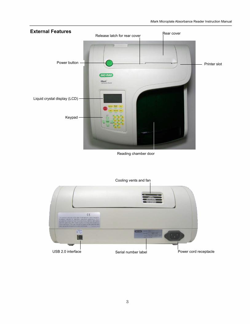
iMark Microplate Absorbance Reader Instruction Manual
4
Keypad Guide Main Returns to MAIN SCREEN StartStop Initiates plate reading using current active protocol Stops plate reading and printing Paper Feed Advances paper strip in internal printer Print Prints out the plate data and protocol information Edit Enters the Edit Menu and sets up the instrument Memory Recall Reads out protocol and plate data OpenClose Opens or closes the reading chamber door Up Arrow Moves the cursor upward Selects the alphabet or the symbol Left Arrow Returns to the previous screen Moves the cursor to the left Down Arrow Moves the cursor downward Selects the alphabet or the symbol Right Arrow Moves the cursor to the right Changes or selects the value and type Enter Completes or seals a field entry
DotFunction Inputs the dot Changes the input mode Ten Keys Inputs numbers or well type in plate mapping
0 EMP Empty 5 QC QC control 1 SMP Sample 6 CAL Calibrator 2 BLK Blank 7 CP Positive Control 3 STD Standard 8 CN Negative Control 4 CO Cutoff control 9 CW Weak Positive Control
OpenClose Edit
Print Paper Feed Main
START
STOP
Memory Recall
7 CP
8CN
9CW
4 CO
5QC
6CAL
2BLK
3STD
0 EMP
0FUNC
SMP
1
Change
ENTER
Back
Z = A gt
A = Z gt + minusbullbull
iMark Microplate Absorbance Reader Instruction Manual
5
Instrument Setup Unpacking the Instrument The shipping carton contains the following items
bull iMarktrade Microplate Reader with 415 nm 450 nm 490 nm 595 nm 655 nm and 750 nm interference filters installed on the filter wheel
bull Power cord
bull USB cable
bull Dust cover
bull Instruction manual
bull Warranty card
bull One roll of thermal printer paper
Inspect the exterior of the instrument for any signs of shipping damage Contact your local Bio-Rad representative if any of these items are damaged or missing
Initial Instrument Startup 1 Place the instrument on a clean sturdy table or bench It is important to keep the instrument in a clean
relatively dust free environment to ensure optimal performance
2 Connect the power cord to the back of the instrument Before connecting the instrument to the main electrical supply check that the AC voltage is appropriate for the instrument
3 To turn the power on press the green power button on the top of the instrument The LCD will display the version number of the on-board firmware After about three seconds the instrument will perform an initial self-diagnosis that requires about fifteen seconds The login screen displays for you to choose your user level (administrator or common user) and enter the password (initial password 00000) Please allow three minutes for the instrument to warm up (reach thermal equilibrium) before reading plates
Change password Select ldquoChange Passwordrdquo in the Security Menu
Enter the current Password then move the cursor to the 3rd line and enter a new password Press Enter to complete the field entry The system will return to the previous Security Menu
Change user mode Select ldquoChange userrdquo in the Security Menu
Select a desired user mode by pressing the Right Arrow key Enter the appropriate password for the selected user mode Press Enter to complete the field entry The system will return to the previous Security Menu
System Login User Administrator Password Press ENTER
iMark Microplate Absorbance Reader Instruction Manual
6
4 Install the printer paper The thermal printer paper is printable on one side only and must be properly installed for the printer to function The outside of the roll is the printable side
a Open the rear cover of the instrument b Tear off a small piece at the beginning of a new roll at an angle to form
a point c Place the roll of paper in the small pan-like holder positioned below
the printer The roll should be positioned so that it will feed from the bottom
d While pressing the PAPER FEED key feed the pointed end of the paper into the paper feed slot in the underside of the printer until the printer grabs the paper and feeds it through the slot in the top of the instrument
e Securely close the rear compartment
Multi-language support The iMark LCD can produce text in three languages English Russian and Chinese To switch to English from Russian or Chinese press the Main button then the Edit button to get to the configuration screen Press the downward-pointing arrow on the key pad six times to navigate to the language options line Press Enter twice to select English and then press Enter a third time to shut down the reader When restarted the iMark will display in English
Instrument Shutdown To shut down the instrument press the green power button on the top of the instrument for a few seconds Then the LCD will display a Power off Yes or No screen Select ldquoYesrdquo to shut down the instrument
Power off gtgtYes No
iMark Microplate Absorbance Reader Instruction Manual
7
Software Overview Capabilities The iMark Microplate Reader has on-board software that allows the user to set the plate reading and data analysis conditions to save these settings as a test protocol to read a microplate under this protocol and to print reports from the built-in printer The software communicates through the 4-line 20-character LCD and is controlled through the instruments membrane keypad
The software has three different protocol types End-point analysis Kinetic analysis and Checkmark validation The Checkmark validation function is used only by the administrator to verify quality control
The display shows the current mode The user can choose between these protocol types or can press the Memory Recall key to use the current protocol type
Quick Guide to Reading a Plate 1 Turn on the instrument Allow about 30 seconds for self-diagnosis The instrument needs to warm up for
about three minutes prior to reading a plate
2 Upon power up the login screen will appear Enter the login password (initial password 00000) press Enter
3 Program a protocol for your assay See page 22 for information on Editing a Kinetic protocol or page 25 for Editing an End Point Protocol Make sure filters installed correlate with information entered in reader firmware
4 Select the protocol of choice if programmed See the Memory Recall section on page 21 for detailed operation
5 Review or print parameters set in the protocol See the Editing End Point Protocol section on page 25 for details
6 Verify settings on Cutoff Report Limit STDs Mode Mapping and kit name parameters are as desired
7 Protocol setting can be printed see the Printing Reports and Protocols section on page 20 for information
8 All reports other than the raw data report require plate mapping Set the plate map with instructions from the Plate Map Setting Procedure section on page 33
9 The Matrix and Limit reports require assignment of upper and lower limits Set the upper and lower limits in the Editing End Point Protocol Limit setting window
10 The Cutoff report requires definition of the cutoff setting Refer to the Cutoff Setting Procedure section on page 26
11 The Curve fit and Concentration reports require that standard concentration and locations must be defined Refer to page 29 for details on how to define the standards and the curve fit parameters
12 Set the general reading mode (single or dual wavelength reading plate shaking read mode) following the instructions in the Mode Setting Procedure section on page 32
After warm-up is complete
13 Press the ldquoMainrdquo key The main screen appears on the LCD
14 Carefully place the microplate in the reading chamber Press the ldquoStartStoprdquo key to read
iMark Microplate Absorbance Reader Instruction Manual
8
Instrument Functions Calculations The Microplate Reader uses Beers Law to calculate the absorbance value of each well Beers Law states that absorbance is equal to the log10 of the ratio of the baseline measurement intensity (Io) to the sample measurement intensity (I)
Beers Law Absorbance = Log10 (IoI)
Before measuring the plate the reader takes a reading for all eight photodiode channels These values are recorded as the baseline measurement (Io) values for each channel respectively The reader then records the sample measurement (I) value for each well and calculates the absorbance using these values Channel-to-channel error is significantly reduced because the Io value for a given channel is used only in determining the absorbance of the wells of that channel
Security password The iMark Microplate Reader requires a user login with password This security feature helps to prevent any unwarranted modifications to the analysis conditionsprotocols and data stored in the instrument and identifies the operator on reports The reader has two user settings the Administrator and the Common user Each user level has its own security password
Memory Back-Up The battery back-up provides memory even after the reader is turned off
The following information will be saved in the memory until new reading parameters are set by the user or a new plate is read by the instrument Note that if a run is aborted before it is finished all the previous plate reading data remain in memory and none of the data from the aborted reading is stored
bull The ten latest sets of End-point protocol plate reading results
bull The two latest sets of Kinetic plate reading results (max 30 series of readings for each Kinetic Protocol)
bull 64 End-point Protocol settings and 2 Kinetic Protocol settings
bull A set of Checkmark reference data and the one latest set of Checkmark reading result
bull A set of standard curve data for the storage of standard curves and graphs
bull Eight wavelength values for filters
bull Laboratory name
bull Two security passwords (for the Administrator and the Common user)
bull Instrument serial number
In addition to the battery back-up memory the instrument has a small amount of non-volatile memory to keep the system information after the battery is dead The serial number is stored in this memory The average battery life is 5 years
iMark Microplate Absorbance Reader Instruction Manual
9
The first time the instrument is turned on or after a battery failure the following default information is held in the memory
1 Both Administrator and Common user security passwords are set to 00000
2 Laboratory name is Bio-Rad Laboratories
3 All wavelength values of the filters are set to --- nm
4 The date and time of the calendar chip are set to 1 day 1 month 00 year 0 hour and 0 minute
5 No plate reading data is available
6 End-point protocol is chosen and the protocol number is set to 1
7 No standard curve data for the storage of standard curves and graphs is available
Limits The Microplate Reader displays absorbance readings with absolute values as 3500 Out-of-range absorbance values (those with absolute values greater than 3500) are displayed as either or - For example if the absorbance is 4500 then the display will read and if the absorbance is -4500 the display will read -
iMark Microplate Absorbance Reader Instruction Manual
10
Report Types Two types of reports can be generated End-point protocol and Kinetic protocol Each of these and their subtypes are described below After these descriptions there are flow diagrams that show how to access specific choices
End-point Protocol Reports Nine types of End-Point Protocol reports can be generated raw data absorbance limit matrix cutoff curve fit concentration difference and TeSeE screening reports
1 Raw data report The Raw data report is the uncorrected absorbance values (without blank subtraction) In single-wavelength mode the reported value is the measured absorbance In dual-wavelength mode the reported value is the difference between the uncorrected readings taken with the measurement filter and with the reference filter
2 Absorbance report The Absorbance report is the blank-corrected absorbance values The mean absorbance value of all of the wells designated as assay blanks is calculated and then subtracted from all 96 values of the raw data set to produce the Absorbance report
Abs = Raw ndash Blank mean
Blank mean = Xn
SD = [X^2 ndash n(Blank mean)^2n-1]^12
Where
SD = Standard deviation
X = Sum total of the raw absorbance for each blank
X^2 = Sum total of the squared raw absorbance for each blank
n = Number of blanks
3 Limit report The Limit report provides a qualitative YESNO report Wells with blank-subtracted absorbance values between the upper and lower limits are represented with an asterisk () wells with absorbance values below the lower limit by minus signs (-) and wells with absorbance values greater than the upper limit by positive signs (+)
4 Matrix report The Matrix report provides a qualitative report of the relative magnitude of the absorbance values on the plate The absorbance range defined by the upper and lower limits is divided into 10 equal partitions numbered 0 through 9 The blank-subtracted absorbance value of each well is classified according to the partition of the matrix to which it corresponds and is reported as a signal digit Wells with absorbance values greater than the upper limit are reported by plus signs (+) and wells with absorbance values less than the lower limit by minus signs (-)
iMark Microplate Absorbance Reader Instruction Manual
11
5 Cutoff report The Cutoff report provides a qualitative report of the relative magnitude of the absorbance values or converted concentrations on the plate
Four types of cutoff reports are supported ranged constant single constant formula and ratio These and their subtypes are listed below
a Ranged Constant The user inputs Positive and Negative values to be used as the cutoff
For units designated Abs if the absorbance of a well is within the positive and negative cutoff values the well is scored If the absorbance of a well is greater than the positive value the well is scored + and if the absorbance of a well is below the negative value the well is scored -
For units not designated Abs the absorbance value of each well is converted to the concentration value using the curve fit constants of the curve fit report If the concentration of a well is within the positive and negative cutoff values the well is scored If the concentration of a well is greater than the positive value the well is scored + and if the concentration of a well is below the negative value the well is scored -
b Single Constant The user inputs Positive and Gray zone values to be used as the cutoff
For units designated Abs if the absorbance of a well is within the gray zone value of the positive cutoff value the well is scored If the absorbance of a well is more than the gray zone value and greater than the positive value the well is scored + and if the absorbance of a well is more than the gray zone value below the positive value the well is scored -
Upper cutoff absorbance = Positive absorbance + ((Gray zone100) Positive absorbance)
Lower cutoff absorbance = Positive absorbance ndash ((Gray zone100) Positive absorbance)
For units not designated Abs the absorbance value of each well is converted to the concentration value using the curve fit constants of the curve fit report If the concentration of a well is within the gray zone value of the positive cutoff value the well is scored If the concentration of a well is more than the gray zone value greater than the positive value the well is scored + and if the concentration of a well is more than the gray zone value below the positive value the well is scored -
Upper cutoff conc = Conc of positive controls + ((Gray zone100) Conc of positive controls)
Lower cutoff conc = Conc of positive controls - ((Gray zone100) Conc of positive controls)
c Formula The mean absorbance values of the Positive and Negative wells defined in the plate map are used for the cutoff formula calculation
The 12 types of formula-based cutoff reports are
i k CNx vii k + CNx
ii k CPx viii k + CPx
iii k COx ix k + COx
iv CNx k x kCNx + CPx
v CPx k xi xi (CNx + CPx) k
vi COx k xii k1CNx + k2CPx
iMark Microplate Absorbance Reader Instruction Manual
12
The result absorbance value of the formula calculation and the gray zone value that is entered by the user are used for the cutoff
The upper and lower cutoff values are
Upper cutoff absorbance = Result of a Formula + ((Gray zone100) Result of a Formula)
Lower cutoff absorbance = Result of a Formula - ((Gray zone100) Result of a Formula)
The absorbance range of the upper and lower cutoff is divided into 10 equal partitions numbered 0 through 9 The absorbance value of each well is classified according to the partition of the matrix to which it corresponds and is reported as a signal digit Wells with absorbance values greater than the upper cutoff are reported by plus signs (+) and wells with absorbance values less than the lower cutoff by minus signs (-)
d Ratio The mean absorbance value of the Calibrator wells defined in the plate map and the concentration value entered by the user are used for the cutoff ratio Before the cutoff the absorbance value of each well is converted into the concentration value The ratio of ConcentrationAbsorbance of Calibrator is applied to the conversion Then the cutoff is done with the defined Positive and Negative or the defined Positive and Gray zone values
6 Curve Fit Report The Curve fit report provides a regression analysis based on the absorbance values of a series of standards There are ten types of curve fits supported with the onboard software on iMark Microplate readers
i 5P Logistic Rodbard ii 4P Logistic Rodbard iii 5P Logistic Cook-Wilkenson iv 4P Logistic Cook-Wilkenson v 5P Exponential vi Sigmoid Logistic vii Linear regression viii Quadratic regression ix Cubic x Point-To-Point regression
The onboard software calculates the best fit of the defined curve between each set of two consecutive data points in the standard curve of absorbance vs concentration And then it generates the report with the coefficients of regression the correlation coefficient and the standard error
For readers with the optional internal printer or with an external ESCP printer which accepts ESCP code a graph of the standard curve may be generated when selected in the report parameter
7 Concentration Report In case of the curve fit the Concentration report also provides the regression analysis After the calculation of the curve fit it calculates the concentrations values of the samples and generates the report
In case of the cutoff constant with the unit not designated Abs and in case of the cutoff ratio the reader generates the list of concentration of each well
8 Difference Report The Difference report is the subtraction report between the neighboring columns or row
iMark Microplate Absorbance Reader Instruction Manual
13
9 TeSeE Screening Report Analysis of the TeSeE screening assay results can be done with two pre-programmed protocols ldquoTeSeErdquo protocol is stored in Endpoint Protocol position 5 and ldquoTeSeE eqrdquo is stored in Endpoint Protocol position 6 as factory default setting Both protocols are locked
TeSeE screening report is generated only if these protocols are selected as current active protocol Plate is first validated according to negative and positive controls validation criteria samples are then compared to the calculated cut-off
Criteria for plate validation are set as follows
Criteria 1 Individual Negative Control must be lt 0150
Number of valid Negative Control must be gt= 3
Criteria 2 Individual Negative Control must be lt 1400 Negative Control average
Number of valid Negative Control must be gt= 2
Criteria 3 Positive Control average must be gt= 1000
Cutoff is calculated as follows
TeSeE
Positive cutoff = Negative Control average + 0210
Negative cutoff = (Negative Control average + 0210) 0900
TeSeE eq
Positive cutoff = Negative Control average + 0210
Negative cutoff = Negative Control average + 0090
Samples are interpreted as follows
ldquoPOSrdquo Positive when sample OD gt= Positive cutoff
ldquoNEGrdquo Negative when sample OD lt Negative cutoff
ldquordquo Gray zone NEG cutoff =lt sample OD lt POS cutoff
iMark Microplate Absorbance Reader Instruction Manual
14
Protocol
Security
Filters
Date Set
Lab name
Cutoff
Report
Limit
STDs
Mode
Mapping
Kit name
Not Used
Constant
Control
Formula
Ratio
Ranged Cutoff Single Cutoff
Ranged Cutoff Single Cutoff
12 choices of cutoff formula
Concentration
Unit
Cutoff value
Cutoff Values setting Gray zone setting when single cutoff
Cutoff Control setting Gray zone setting when single cutoff
Coefficient setting of selected formula
0 - 9999
17 choices of unit
Cutoff Values setting Gray zone setting when single Cutoff
Ranged Cutoff Single Cutoff
Raw(Raw data) Abs(Absorbance) Lim(Limit) Mtx(Matrix) Cut(Cutoff) Crv(Curve fit) Cnc(Concentration) Dif(Difference)
Upper Limit Lower Limit For Limit Report
Standard information
Curvefit
Number of STD Concentration
Unit
Curvefit type Graph axis
Set Photo mode Set Shaking
Set Read mode
Manual mapping
Automatic mapping
Change password
Change user
End-point Analysis Protocol
Up to 12 Standards 0 to 9999 17 choices
12 choices of curve fit type 4 choices of graph axis combination of Log and Linear
SingleDual Wavelength Shake (Yes No) Speed (High Low Mid) Time Read Speed (FastStep) and Read Mode (NormalEval)
Func key to switch [N] to [F] [N] for sample number [F] for sample
Func key to switch from [ABC] to [abc] to [sym] key to move cursor
For current user mode Administrator or common user Administrator has power to switch
Filter wavelength setting for 1-8 positions ldquo0rdquo for no filter
DayMonthYear HourMin
Func key to switch from [ABC] to [abc] to [sym] key to move cursor
Save STDC
Language
Save STD Curve
Rename STD Curve
Select Language
5 choices of storage number
5 choices of STD curve
Func key to switch from [ABC] to [abc] to [sym] key to move cursor
Choices of pre-installed language for LCD and report printout
BlankCNCWCPCOQCCalibratorSampleReplicate well
Recall Setting Select STD Curv
Recall YesNo Selection 5 choices of memorized STD curve
Edit
Bold for menu pages
LCD adj and key to change contrast
Italic for program pages
iMark Microplate Absorbance Reader Instruction Manual
15
Kinetic Protocol Reports Four types of Kinetic protocol reports can be generated absorbance kinetic plots linear regression and GALT reports
1 Absorbance Report The Kinetic Absorbance report is the series of absorbance data in the kinetic sequence
2 Kinetic Plots Report The Kinetic plots are the absorbance plots of each well in the plate It is available for readers with the optional internal printer or with an external ESCP printer which accepts ESCP code
3 Linear Regression Report The Linear Regression report provides the calculation of Kinetic reaction rate for each well using the linear regression
4 GALT Report The GALT report calculates the following formula for each well between two readings of a plate
GALT = (R2 ndash R1) k
Where R1 = Absorbance value of 1st reading
R2 = Absorbance value of 2nd reading
k = GALT factor
iMark Microplate Absorbance Reader Instruction Manual
16
Func key to switch from [ABC] to [abc] to [sym] key to move cursor
Func key to switch from [ABC] to [abc] to [sym] key to move cursor
Func key to switch from [ABC] to [abc] to [sym] key to move cursor
DayMonthYear HourMin
Filter wavelength setting for 1-8 positions ldquo0rdquo for no filter
Edit
Kinetic Analysis Protocol
Protocol
Security
Filters
Date Set
Lab Name
Change password
Change user
LockUnlock
Mode
Report
Calc
Mapping
Assay
Kit name
Reading Inter
Shaking Phmode
Speed
Number of reads (2-30) start delay time (0-999) Reading interval time Shake (FirstEverydisable) Speed (High Low Mid) Time Single Dual wavelength Read Speed (FastStep)
CC Limit (correlation coefficient limit) Calcrange (calculation range of reading number) for Linear regression Report
GALT factor k input (0- 9999) Result = (2nd read ndash 1st read)k for GALT Report
Manual mapping
Automatic mapping
Func key to switch [N] to [F] [N] for sample number [F] for sample type
General Kinetic or GALT assay assay type selection
Absorbance KINETIC Plots Linear regression when General Kinetic Assay selected GALT report when GALT Kinetic assay selected
For current user mode Administrator or Common user Administrator has power to switch
Special Buttons
Memory Recall
Main
Protocol Plate Data
Report Protocol
End point Kinetic
Checkmark
1-64 End point protocol storage 1-2 Kinetic protocol storage Checkmark reader test
Printout
Returns to MAIN screen
SaveSTDC
Language
BlankCNCWCPCOQCCalibratorSampleReplicate well
Save STD Curve
Rename STD Curve
Select Language
5 choices of storage number
5 choices of STD curve
Choices of pre-installed language for LCD and report printout
Bold for menu pages
LCD adj and key to change contrast
Italic for program pages
iMark Microplate Absorbance Reader Instruction Manual
17
Screen by Screen Procedures Initial Startup
01Kinetic-1 M405(1)R605(6)30read Shake999sMidEvery 382402 180901
End point mode
Kinetic mode
Self-diagnosis iMark Microplate Reader 1305 180901
System Login User Administrator Password Press ENTER
Login SCREEN
01EndPoint Assay01 M405(1)R655(6) Shake999sMid 382402 180901
Checkmark Validation Program
180901
Checkmark mode
Initializing reader
MAIN SCREEN
Self-Diagnosis This screen will appear upon power-up and during self-diagnosis Date and time are also indicated on this screen
Initialization After self-diagnosis the system initializes all the hardware
Security Check The system requires a password to confirm that the user is the authorized operator Pressing the ChangeRight arrow key will switch the user mode between Common user and Administrator Password for both Common user and Administrator is set as ldquo00000rdquo upon factory shipment Operator can change the password in the EDIT menu See Security
System Ready When this MAIN screen is on the LCD the StartStop key can be pressed for microplate reading Pressing StartStop key will begin reading with the current protocol There are three kinds of MAIN screens depending on the current protocol type Endpoint Kinetic and Checkmark program The four arrow keys Numeral keys Main key and Enter key are inactive StartStop Memory Recall Edit Print and Paper Feed keys are active
01EndPoint Assay01 M405(1)R655(6) Shake999sMid
180901
Kit name for current active protocol
01Kinetic-1 M405(1)R605(6)30read Shake999sMidEvery 382402 180901
Kinetic M Measurement wavelength and its position in the filter disk R Reference wavelength and its position in the filter disk Number of reading for KINETIC
Storage number in memory of current active protocol
Plate shaking parameters period in seconds and speed
M Measurement wavelength and its position in the filter disk R Reference wavelength and its position in the filter disk
Date (day month year)
Plate shaking parameters Period in seconds Speed (fast middle slow) Mode (before every read before first read and no shake)
End point
iMark Microplate Absorbance Reader Instruction Manual
18
Configuring the System NOTE To return to the previous screen use the backleft arrow key
Edit Menu
Security function raquoChange Password bullChange user bullLockUnlock Prtl
Change Password
LockUnlock
Change user
Change Password Current New Common user
Security for current active Protocol [Lock] Unlock
System Login User Administrator Password Press ENTER
Change Password Select ldquoChange Passwordrdquo in the Security Menu Enter the current password then move the cursor to the 3rd line and enter a new password Press Enter to complete the field entry The system will return to the previous Security Menu Change User Mode Select ldquoChange userrdquo in the Security Menu Select a desired user mode by pressing the Right Arrow key Enter the appropriate Password for the selected user mode Press Enter to complete the field entry The system will return to the previous Security Menu LockUnlock Protocol Select ldquoLockUnlock Prtlrdquo in the Security Menu Move the selected mark ldquo[ ]rdquo to the desired position Lock or Unlock using the Right Arrow key Press Enter to complete the field entry The system will return to the previous Security Menu If ldquoLockrdquo is selected the current active protocol will be protected against modification made by a Common user If ldquoUnlockrdquo is selected the current active protocol can be modified by any user mode NOTE Only the Administrator has authority to lock and unlock the Checkmark Protocol
Edit Menu This menu can be accessed by pressing the Edit key in the MAIN SCREEN
Security Menu Security Setting Select ldquoSecurityrdquo in the Edit Menu screen and press Enter The Security Menu appears on the screen
raquoProtocol Labname Security SaveSTDC Filters Language Date set LCD adj
iMark Microplate Absorbance Reader Instruction Manual
19
1400nm 5650nm 2450nm 6nm 3475nm 7nm 4650nm 8nm
Filter
DayMonthYear 16 05 01 Hour Minutes 18 55
Date set
Enter Lab name Bio Rad Laboratories uarr [ABC]
Lab name
Filter Setting Move the cursor to the desired position by using the Up Down and Right arrow keys Enter the filter wavelength on the selected position using the number keys If the selected position of the filter disk is empty enter three ldquordquo Press Enter to complete the field entry The system will return to the previous Edit Menu screen
Calendar Setting Move the cursor to the desirable position for date or time input by using the Up Down and Right arrow keys Enter the present date or time using the number keys Press Enter to complete the field entry The system will return to the previous Edit Menu screen
Lab Name Setting Use the Up and Down arrow keys to select from ldquoArdquo to ldquoZrdquo and symbols Use the Number keys for numeric input Use the Right arrow key to move the cursor to the right Use the Left arrow key to return the cursor to the Edit Menu screen Pressing the FUNCrdquo key will toggle the character mode between Upper case alphabet Lower case alphabet and symbol The current character mode is indicated on the lower right corner of the LCD
Save STD Curve gt Save STD Curve Rename STD Curve
Save STDC Save STDC Setting Select ldquoSave STDCrdquo in Edit Menu screen above and press Enter The Save STD Curve Menu appears on the screen Move the cursor to the desired position by using the Up and Down arrow keys
Select STD storage gt 1120304 1500 2 3150304 1030
Select for renaming gt 1160304 1125 2 3150304 1030
Save STD Curve To save a STD Curve select the storage number between 1 and 5 Use the Up and Down arrow keys to move the cursor to the desired storage number and press Enter to complete the selection After the storage number selection the rdquoAre you surerdquo message appears Select ldquoYesrdquo or ldquoNordquo and press Enter In case of ldquoYesrdquo the reader saves the STD Curve and returns to the Edit Menu screen If the curve fit calculation is not done or has not finished successfully an error message will appear and the STD Curve will not be saved STD curve does not
exist yet Press any key
Save STD Curve 1160304 1125 Are you sure gt Yes No
Rename STD Curve To change a name of an STD Curve select a storage number between 1 and 5 Use the Up and Down arrow keys to move the cursor to the desired storage number and press Enter to complete the selection Use the Up and Down arrow keys to select from ldquoArdquo to ldquoZrdquo and symbol Use the Number keys for numeric input Use the Right arrow key to move the cursor to the right Use the Left arrow key to return the cursor to the Edit Menu screen Pressing the FUNCrdquo key will toggle the character mode between Upper case alphabet Lower case alphabet and symbol The current character mode is indicated on the lower right corner of the LCD
1160304 1125 gtSTD Curve 1 lt
[ABC]
Save STD Curve
Rename STD Curve
iMark Microplate Absorbance Reader Instruction Manual
20
Printing Reports and Protocol information
Print menu raquoReports bullProtocol
Print Menu Print Menu Access this menu screen by pressing the Print key in the MAIN screen Printing Reports Select ldquoReportsrdquo and press Enter to print the current active plate data report Printing Protocol Information Select ldquoProtocolrdquo and press Enter to print all parameter settings in the current active protocol Stop Printing Press the StartStop key during printing to stop the print job immediately When printing is completed the system automatically returns to the MAIN screen
Select Language raquoEnglish bull bull bull
Language Changing Language Select a desired language using the Up and Down arrow keys and press Enter to complete the selection The system will generate a message for an immediate power off to restart Select ldquoYesrdquo and press Enter to activate the selected new language The newly-changed language will be applied to the LCD screen and printed reports Power off
gtgtYes No
LCD Contrast 12345678901234567890
laquo 26 raquo ENTER to complete
Adjusting LCD Contrast Adjust LCD contrast by using the Right and Left arrow keys and press Enter to complete the adjustment
LCD adj
iMark Microplate Absorbance Reader Instruction Manual
21
Memory Recall Operation
01 200500 1400 02raquo210500 1700 03 200500 1800 darr04raquo200500 1900
01raquo200500 0900 02raquo200500 1000
Memory Recall raquoProtocol bullPlate Data
Protocol type menu
Data type menu
End Point
Kinetic
End Point
Kinetic
Memory Recall Menu
Select protocol type raquoEnd Point
bullKinetic bullCheckmark
Select Protocol 02 uarrraquo Protocol -2 Protocol -3 darr Protocol -4
Select Protocol 01 raquo Kinetic -1 GALT
Select data type raquoEnd Point
bullKinetic bullCheckmark
200501 0900
Checkmark
Checkmark program has been activated Press any key
Checkmark
Selecting Protocol Move the cursor to the position of the desired protocol and press Enter to complete the selection NOTE ldquordquo indicates the currently activated protocol and ldquordquo indicates a security locked protocol There is no protocol selection with ldquoCheckmarkrdquo When a protocol is selected the system will then automatically return to the MAIN screen
Changing Current Active Protocol Select ldquoProtocolrdquo in Memory Recall menu above and press Enter The Select Protocol type menu will appear on the screen Select a protocol using the Up and Down arrow keys Press Enter to complete the selection
Selecting Plate Data Move the cursor to the position of the desired plate data and press Enter to complete the selection NOTE ldquordquo indicates the currently activated plate data There is only one storage for ldquoCheckmarkrdquo data When plate data is selected the system automatically returns to the MAIN screen
Changing Current Active Plate Data Select ldquoPlate Datardquo using the Memory Recall button and press Enter The Data type menu will appear Use the Up and Down arrow keys to select a plate data type Press Enter to complete the selection
This menu screen can be accessed by pressing the Memory Recall key in the MAIN screen
iMark Microplate Absorbance Reader Instruction Manual
22
Editing the Kinetic Protocol
Select ldquoProtocolrdquo in the Edit Menu and press Enter The Kinetic Protocol menu will appear on the screen if the current active protocol type is Kinetic
Reading speed [Fast mode] Step mode
Speed
raquoReading Speed Inter Shaking Phmode
Kinetic Mode
Kinetic Protocol Menu
raquoMode Report Calc Kit name Mapping Assay
This menu screen can be accessed by selecting ldquoModerdquo in the Kinetic Protocol menu above
Number of Reading = 20 (2-30) Start Delay time = 25 sec(0-999)
Reading
Number of Reading = 2 Start Delay time = 25 sec(0-999)
Number of Readings and Start Delay Time Setting Press the Up or Down arrow key to change the number Enter the appropriate numbers with the numeral keys and press Enter to complete the field entry The system will return to the Kinetic Edit Menu If GALT is the current assay type the number of reading fields is fixed at 2 Press the StartStop key to set the Start Delay time enter a value and press Enter until the reading starts
1-gt2raquo 100 sec 2-gt3 100 sec 3-gt4 100 sec darr4-gt5 100 sec
Inter Use same interval between all reads
raquoYes No
Setting Reading Intervals The system prompts the operator to set a reading interval before each plate run Move the cursor to the desired selection ldquoYesrdquo or ldquoNordquo and press Enter The system generates the interval entry screen Move to the active entry field by pressing the Up and Down arrow keys and enter appropriate numbers using numeral keys Press Enter to complete all field entries The system will return to the Kinetic Mode menu
Photometric Dual Measurement405 nm Reference 655 nm
Ph mode Photometric Mode Setting When the ldquoPhotometricrdquo field is activated pressing the Right arrow key will switch the field entry ldquoSinglerdquo lt-gtrdquoDualrdquo Pressing the Up or Down arrow keys will move the cursor to the next entry field Pressing the Right arrow key when the wavelength field is activated will change the wavelength to the next available selection installed in the reader Press Enter to complete all field entries
Shaking parameters Before Every read Speed Mid Time 999 sec
Shaking Plate Shake Parameters When the ldquoBeforerdquo field is activated pressing the Right arrow key will change the field entry ldquoEveryrdquo-gtrdquo--rdquo-gtrdquoFirstrdquo-gt When the ldquoSpeedrdquo field is activated pressing the Right arrow key will change the field entry ldquoMidrdquo -gtrdquoHirdquo-gtrdquoLowrdquo-gt When the ldquoTimerdquo field is activated enter the time value for plate shaking period using the numeral keys Press Enter to complete all field entries
Selecting Reading Speed Use the Up or Down arrow keys to switch the selection Press Enter to complete the selection
Edit Menu raquoProtocol Labname Security bullSaveSTDC Filters bullPrinter Date set
This menu screen can be accessed by pressing the Edit key in the MAIN screen
iMark Microplate Absorbance Reader Instruction Manual
23
Kit name for 01 raquoGAP TEST IgGlaquo uarr [ABC]
Kit name
Calculation
Mapping
Assay
Assay type selection raquo[General KINETIC] GALT assay
Calculation Param CC Limit 0910
Calcrange 10 - 20
Select Mapping mode raquoManual mapping bullAutomatic mapping
raquo[Linregression] bullAbsorbance bullKINETIC Plots
Report
Plate Mapping See Plate Map setting procedure
Result = (R2 ndash R1)k k = 999999 R11st Reading R22nd Reading
If GALT
Setting the Kit Name Use the Up and Down arrow keys to select alphabet from ldquoArdquo to ldquoZrdquo and space Use the Number keys for numeric input Use the Right arrow key to move the cursor to the right Use the Left arrow key to return to the Protocol Menu screen Pressing ldquoFUNCrdquo key will change the character mode Upper case alphabet -gt Lower case alphabet -gt symbol The current character mode is indicated on the lower right corner of the LCD
Kinetic Protocol Menu
Selecting Kinetic Assay Type Move the cursor to the desired Assay type by pressing the Up or Down arrow keys Press Enter to complete the selection The item with mark ldquo[ ]rdquo is the currently selected item GALT assay Result = factor x (2nd Read ndash 1st Read)
Selecting Report Type Move the cursor to the desired report type by pressing the Up or Down arrow keys Pressing the Right arrow key will select or deselect the item Press Enter to complete the selection Note When GALT assay is selected ldquoGALT reportrdquo shall be the only one option on this screen
raquoMode bullReport bullCalc bullKit name bullMapping bullAssay
Calculation Parameter Setting When the ldquoCC Limitrdquo field is activated pressing the numeral key will enter the desired numbers Press Enter to complete all field entries If the GALT Reports is activated pressing the numeral keys will enter the desired numbers Press Enter to complete all field entries
iMark Microplate Absorbance Reader Instruction Manual
24
Checkmark Value Setting (Administrator only)
raquoSerial Report bullLinearity ref bullMaxCV bullFilter Check ref
Checkmark Protocol Menu
raquoSerial 0000 Reptype Simple
405nm S10158 Linearity S20309 reference S31401 S42109
MaxCV raquoS115 Linearity S205 reference S302 S402
Filter max min 4051875 0329 4501167 0954 darr 4920596 0103
Serial Report
Linearity reference
Max CV
Filter check reference
Filter max min uarr 5401875 0329 6201167 0954 6900596 0103
Setting the Serial Number and Report Type Pressing the Up and Down arrow keys will move the cursor and change the field entry When ldquoSerial rdquo field is active enter the serial number that will be shown in the data sheet of the Checkmark plate using the numeral keys When the ldquoRep typerdquo field is active pressing the Right arrow key will switch the report type between ldquoSimplerdquo and ldquoFullrdquo
Setting the Linearity Reference Value Pressing the Up or Down arrow keys will move the field entry from S1 to S4 Pressing the Right arrow key will change the wavelength 405 nm-gt450 nm-gt492 nm-gt540 nm-gt620 nm-gt690 nm Use the numeral keys for the reference value setting Pressing Enter will complete all field entries at all wavelength
Max CV setting Pressing the Up or Down arrow keys will move the field entry from S1 to S4 Use the numeral keys for the Max CV setting Press Enter to complete all field entries
Setting the Filter Check Reference Value Initial screen shows the reference entries for 405 nm to 492 nm and pressing the Down arrow key at the bottom of the screen entries will scroll to the next page for 540 nm to 690 nm Pressing the Up Down and Right arrow keys will move the field entry Use the numeral keys for the filter check reference value setting Press Enter to complete all field entries
Select ldquoProtocolrdquo in the Edit Menu and press Enter The Checkmark Protocol Menu will appear on the screen if the current active protocol type is Checkmark mode
Edit Menu raquoProtocol bullLabname bullSecurity bullSaveSTDC bullFilters bullPrinter bullDate set
This menu screen can be accessed by pressing the Edit key in the MAIN screen
iMark Microplate Absorbance Reader Instruction Manual
25
Editing End Point Protocol
Upper Limit= 2000 Lower Limit= 0000 input range 0ndash3500 Upper gt Lower
Standard menu raquoSTD information
bullCurvefit bullRecall STD Curve
raquoCutoff bullMode bullReport bullMapping bullLimit bullKit name bullSTDs
Cutoff
See Plate Map setting procedure
See Standard setting procedure
See Mode setting procedure
raquo[Not use] bullRatio bullConstant bullContrl bullFormula
raquoSet photo mode bullSet shaking bullSet read mode
Select mapping mode raquoManual mapping bullAutomatic mapping
Mapping
Mode
Report
STDs
Limit
Kit name for 01 raquoGAP TEST IgGlaquo uarr [ABC]
Kit name See Kit name setting in Editing Kinetic Protocol
See Cutoff setting procedure
Select ldquoProtocolrdquo in Edit Menu screen above and press Enter The End point Protocol Menu will appear on the screen if the current active protocol type is End point mode
End Point Protocol Menu
raquo[Raw] bullMtx bullCnc bullAbs bullCut bullDif bullLim bullCrv
If ldquoDifrdquo selected
[Raw] bullMtx bullCncbullAbs bullCut [Dif] bullLim bullCrv raquorow odd-even
Seting the Report Type Use the Up and Down Arrow key to move the cursor and press the Right Arrow key to select or deselect the report type Selected report type is marked as ldquo[ ]rdquo Press Enter to complete the selection
Setting the Limit Value Use the Up and Down Arrow key to move the cursor and enter the OD value using the numeral keys The OD value range is 0000 - 3500 Press Enter to complete the selection
Edit Menu raquoProtocol bullLabname bullSecurity bullSaveSTDC bullFilters bullPrinter bullDate set
This menu screen can be accessed by pressing the Edit key in the MAIN screen
iMark Microplate Absorbance Reader Instruction Manual
26
Cutoff Setting Procedure
Cutoff Setting Menu This menu is entered by choosing Cutoff in the End Point Protocol Menu It is used to set the cutoff type The cutoff type marked with ldquo[ ]rdquo is the current selection The Up and Down arrow keys move the cursor to the desired item in the menu list When the desired parameters have been selected press Enter twice to accept the selection and to continue to the next screen Not use means that the reader does not generate the cutoff report Four types of cutoff are supported
1 Cutoff Constant 2 Cutoff Control 3 Cutoff Formula 4 Cutoff Ratio
a Cutoff Constant
Selection of SingleRanged Cutoff Constant This menu selects Single or Ranged cutoff type The cutoff type marked with ldquo[ ]rdquo is the current selection The Enter key seals the selection and resumes to the next setting screen
Single Cutoff Constant The Numerical keys and the Decimal point key are used to enter the positive and gray zone values The Right arrow key is used to select the unit The Up and Down arrow keys move the cursor to the desired parameter of the single cutoff The Enter key sets all values and selection of the cutoff constant and returns the user to the previous screen Ranged Cutoff Constant The Numerical keys and the Decimal point key are used to enter the positive and negative values The Right arrow key is used to select the unit The Up and Down arrow key moves the cursor to the desired ranged cutoff parameters The Enter key sets all values and selection of the cutoff constant and returns to the previous screen NOTE Two available Cutoff constants are ldquoAbsorbancerdquo and ldquoConcentrationrdquo If Abs is chosen the Absorbance cutoff will be done with the cutoff constant parameters defined and the absorbance report is generated For other units defined in the curve fit setting the Concentration value using the curve fit and then cutoff is done with the cutoff constant parameters defined and the concentration value of each well It is necessary to set the curve fit parameters
raquoNot usex bullRatio [Const] bullContrl bullFormula
raquoPositive gt= 9999 Gray zone 50 Unit moll
raquoPositive gt= 9999 Negative lt 1999 NegativeltPositive Unit moll
raquoRanged cutoff [Single cutoff]
Single cutoff
Ranged
iMark Microplate Absorbance Reader Instruction Manual
27
b Cutoff Control
Selection of SingleRanged Cutoff Control This menu screen selects Single or Ranged cutoff type The cutoff type marked with ldquo[ ]rdquo is the current selection The Enter key seals the selection and resumes to the next setting screen
Single Cutoff Control The Numerical keys are used to enter the gray zone value The unit is fixed to Abs The Enter key sets the value of the cutoff control and returns to the previous screen Ranged Cutoff Control There is no parameter to set for the ranged cutoff control The Enter key returns to the previous screen NOTE CNx is the mean absorbance value of Negative control wells and CPx is the mean absorbance value of Positive control wells These wells are defined in the plate map setting The cutoff is done with the Positive and Negative value to the absorbance value of each well
c Cutoff Formula
Selection of Formula This menu screen selects a formula for cutoff calculation The formula marked with ldquo[ ]rdquo is the current selection The Up and Down arrow keys move the cursor to the desired formula type The movement of the cursor follows the scroll of this screen The Enter key marks the selection and advances the user to the next setting screen The supported formula types are
1 k CNx 2 k CPx 3 k COx 4 CNx k 5 CPx k 6 COx k 7 k + CNx 8 k + CPx 9 k + COx 10 kCNx + CPx 11 ( CNx + CPx ) k 12 k1CNx + k2CPx
Coefficient for Cutoff Formula 1 to 11 The Numerical keys and the Decimal point key are used to enter the coefficient k and gray zone values The Up and Down arrow key moves the cursor to the desired parameter of the cutoff formula The Enter key sets all values of the cutoff formula and returns to the previous screen
Positive gt= CNx Gray zone 50 Unit Abs
Positive gt= CPx Negative lt CNx Unit Abs
Enter key to accept
raquoRanged cutoff [Single cutoff]
Single cutoff
Ranged
Input coefficient k = 001 (001-10) Gray zone 50(0-99)
k CNx k CPx k COx CNx k CPx k COx k k + CNx k + CPx k + COx k CNx + CPx (CNx + CPx) k
uarr raquoCNx k bullCPx k bullCOx k darr bullk + CNx
Select formula raquo[kCNx ] bullkCPx darr bullkCOx
uarr raquok + CPx bullk + COx bullkCNx + CPx darr bull(CNx + CPx) k
uarr raquok1CNx + k2CPx
Page-1
Page-2
Page-3
Page-4
iMark Microplate Absorbance Reader Instruction Manual
28
Coefficient for Cutoff Formula 12 The Numerical keys and the Decimal point key are used to enter the coefficient k1 and k2 and gray zone values The Up and Down arrow key moves the cursor to the desired cutoff formula The Enter key sets the all values of the cutoff formula and returns to the previous screen NOTE CNx is the mean absorbance value of Negative control wells CPx is the mean absorbance value of Positive control wells and COx is the mean absorbance value of Cutoff control wells These wells are defined on the plate map setting The cutoff value is calculated using the defined formula with the defined values and coefficients
d Cutoff Ratio
Ratio to Calibrator In this screen there are three items for setting the ratio to calibrator The Up and Down arrow key moves the cursor to the desired item in the menu list The Enter key seals the selection and resumes to the next setting screen
Concentration of Calibrator The Numerical keys and the Decimal point key are used to enter the calibrator concentration value The Enter key sets the value and returns to the previous screen Unit of Calibrator Seventeen standard units are supported The unit marked with ldquo[ ]rdquo is the current selection The setting procedure is the same as the unit selection of Standards Cutoff Value Setting This menu screen selects Single or Ranged cutoff type The cutoff type marked with ldquo[ ]rdquo is the current selection The Enter key marks the selection and continues to the next setting screen Single Cutoff Control The Numerical keys are used to enter the Positive cutoff concentration value and gray zone value The Enter key sets these cutoff ratio values and returns to the previous screen Ranged Cutoff Control The Numerical keys are used to input the Positive and the Negative cutoff concentration values The Enter key sets these cutoff ratios and returns to the previous screen NOTE The calibrator concentration value is used to convert the absorbance value of each well into a concentration value The ratio of ConcentrationAbsorbance of Calibrator well is applied to the conversion The cutoff uses defined Positive and Negative values to the converted concentration value of each well
Input coefficient k1 = 001 (001-10) k2 = 100 (001-10) Gray zone 50(0-99)
k1 CNx + k2 CPx
Ratio to Calibrator raquoConcentration bullUnit bullCutoff value
Concentration 9999 unit moll
uarrraquo 01 ugdl 02 ngml 03[ pgml] darr 04 pmml
raquoPositive gt= 9999 Gray zone 50
Unit moll
raquoPositive gt= 9999 Negative lt 9999 NegativeltPositive
Unit moll
raquoRanged cutoff [Single cutoff]
Concentration
Unit
Cutoff value
Single cutoff
Ranged cutoff
iMark Microplate Absorbance Reader Instruction Manual
29
Standard Setting Procedure
Standard Curve Setting Menu This menu screen is entered by choosing STDs in the End Point Protocol Menu screen It is used to set the concentration data and the curve fit type for a standard curve or to recall a memorized standard curve The Up and Down arrow key moves the cursor to the desired item in the menu list The Enter key seals the selection and continues to the next setting screen
a STD Information Setting
STD Information In this screen there are three items for setting the concentration data of standards The Up and Down arrow keys move the cursor to the desired item in the menu list The Enter key seals the selection and continues to the next setting screen
Number of Standards The Numerical keys are used to enter the number of standards ldquo0rdquo means that the curve fit report is not used The Enter key sets the number and returns to the previous screen The maximum number of standards is 12 Concentration The Numerical keys and the Decimal point key are used to enter the concentration values of standards The Up and Down arrow keys move the cursor to the desired position The movement of the cursor also follows the scroll of this screen The Enter key sets all values of the concentration of standards and returns to the previous screen Unit Seventeen units are supported The unit marked with ldquo[ ]rdquo is the current selection The Up and Down arrow keys move the cursor to the desired unit type The movement of the cursor also follows the scroll of this screen Press Enter twice to select the unit type and to return to the previous screen The supported types of unit are
1 moll 11 pgml 2 m moll 12 Uml 3 u moll 13 IUml 4 n moll 14 uIUml 5 p moll 15 mIUml 6 mgl 16 EU 7 ngl 17 Arbit 8 pgl 9 ugdl 10 ngml
STD information raquoNumber of STD bullConcentration bullUnit
STD 1 0512 STD 2 1012 STD 3 1512 darr STD 4 2053
Standard menu raquoSTD information bullCurve fit bullRecall STD curve
Concentration
Number of STD
Number of STD = 05 (0 2ndash12)
uarrraquo 01 ugdl 02 ngml 03[ pgml] darr 04 pmml
Unit
iMark Microplate Absorbance Reader Instruction Manual
30
b Curve Fit Setting
Curve Fit In this screen there are two choices to set the curve fit The Up and Down arrow keys move the cursor to the desired item in the menu list The Enter key seals the selection and resumes to the next setting screen
Curve Fit Type 10 types of curve fit are supported as below The curve fit type marked with ldquo[ ]rdquo is the current selection The Up and Down arrow key moves the cursor to the desired curve fit type The movement of the cursor follows the scroll of this screen Press Enter twice to select the unit type and to return to the previous screen The supported curve fit types are
1 5P Logistic Rodbard 2 4P Logistic Rodbard 3 5P Logistic Cook-Wilkenson 4 4P Logistic Cook-Wilkenson 5 5P Exponential 6 Sigmoid Logistic 7 Linear regression 8 Quadratic regression 9 Cubic 10 Point To Point regression
Graph Axis Four types of graph are supported The curve fit type marked with ldquo[ ]rdquo is the current selection The Up and Down arrow keys move the cursor to the desired graph type Press Enter twice to select the unit type and to return to the previous screen The supported graph types are
1 Log - Log 2 Log - Linear 3 Linear - Log 4 Linear - Linear
uarr 5p logisticRodb raquo 4p logisticRodb [5p logisticCook] darr 4p logisticCook
raquo X-Log Y-Log [X-Log Y-Lin] X-Lin Y-Log X-Lin Y-Lin
Curve fit type
Graph axis
Curve fit setting raquoCurve fit type bullGraph axis
iMark Microplate Absorbance Reader Instruction Manual
31
c Recall STD Curve Setting
Recall Setting of Standard Curve In this screen there are two items for setting the Recall STD curve as below The Up and Down arrow keys move the cursor to the desired item in the menu list
1 Recall setting (YesNo) 2 Selecting the storage number of standard curves (1 -gt 5)
Recall Setting Move the cursor to the desired position using the Up Down or Right arrow keys Enter key accepts the setting and returns the user to the standard menu screen
Yes Recalling of the standard curve is active No Recalling of the standard curve is inactive
Storage Number Selection Five memories are selectable The vacant memory (marked with asterisks on the date and time field) is also selectable It is necessary to save a standard curve before using its protocol Move the cursor to the desired position using the Up and Down keys This setting screen consists of two parts The Right arrow key is used to switch the indication field between the date and time to the standard curve name Move the cursor to the desired position using the Up and Down keys The Enter key accepts the storage number and returns to the standard menu screen NOTE If the recall of standard curve is active (the recall setting is ldquoYesrdquo) the standard information setting and the curve fit setting will be invalidated and their setting screens will not open
Recall STD curve raquoRecall setting bullSelect STD curve
Recall setting raquoYes No
Recall setting
Select STD Curve raquo1160304 1125
2 darr 3150304 1030
Select STD Curve uarrraquo4
5
Select STD Curve raquo1 STD Curve 1
2 STD Curve 2 darr 3 STD Curve 3
Select STD Curve uarrraquo4 STD Curve 4
5 STD Curve 5
Select STD curve
Right arrow key
iMark Microplate Absorbance Reader Instruction Manual
32
Mode Setting Procedure
Mode Setting Menu This menu screen is entered by choosing the Mode in the End Point Protocol Menu screen or the Kinetic Protocol Menu screen It is used to set the plate reading conditions The Up and Down arrow keys move the cursor to the desired item in the menu list The Enter key seals the selection and resumes to the next setting screen
a Set Photo Mode
Photo Mode In this screen the user chooses Single or Dual wavelength measurement and assigns the measurement and reference (for dual wavelength measurement) filters The assignment of the reference filter appears for dual wavelength measurement The Up and Down arrow keys move the cursor to the desired parameter The Right arrow key chooses SingleDual wavelength measurement and selects the installed filter on the Filters of Edit Menu screen The Enter key seals the selection and returns to the previous screen
b Set Shaking
Shaking In this screen the user selectsdeselects shaking function sets the shaking strength and enters the shaking time A shaking time of 0s indicates no shaking The maximum shaking time is 999 seconds The Up and Down arrow key moves the cursor to the desired parameters The Right arrow key toggles between YesNo (SelectDeselect) shaking or selects strength LowMiddleHigh The Numerical keys are used to enter the shaking time The Enter key seals the selection and returns the user to the previous screen
c Set Read Mode
Read Mode In this screen the user chooses Fast or Step reading and also chooses Normal or Evaluation mode The ldquo[ ]rdquoindicates the current selection The Up and Down arrow key moves the cursor to the desired parameters The Right arrow key chooses FastStep speed or chooses NormalEval mode The Enter key seals the selection and returns to the previous screen The followings are the description of each read mode parameter Reading speed
Fast reading 6 secsingle wavelength reading 10 secdual wavelength reading
Step reading 15 secsingle wavelength reading 30 secdual wavelength reading
Reading mode
Normal mode Plate reading once Evaluation mode Four plate readings per one of measurement are performed and
the average data of their plate readings is generated as a plate data
Photometric Dual Measurement400 nm Reference 655 nm
Set Shake parameters ShakeYes SpeedMid Time 199sec(0-999)
raquoReading speed [Fast ] Step bullRead mode [Normal] Eval
raquoSet Photo mode bullSet shaking bullSet read mode
Photometric Single Measurement400 nm
iMark Microplate Absorbance Reader Instruction Manual
33
Plate Map Setting Procedure
Select Mapping Mode Menu This menu screen is entered by choosing Mapping in the End Point Protocol Menu screen or the Kinetic Protocol Menu screen It is used to map the plate format The Up and Down arrow keys move the cursor next to the desired item of menu list The Enter key seals the selection and changes this screen to the next setting screen
a Manual Mapping
Manual Mapping In this screen the user can set the plate format manually Ten well types can be set Well types The supported well types are
Well type Indication on LCD
1 Blank B 2 Sample X00hellipX99 3 Standard S01hellipS99 4 In-kit Control Positive Control CP0hellipCP9 5 Weak Positive Control CW0hellipCW9 6 Negative Control CN0hellipCN9 7 Cutoff Control CO0hellipCO9 8 Calibrator CL0hellipCL9 9 QC Control QC0hellipQC9 10 Empty well -
The key assignments of well type are ldquo0EMPrdquo Empty well ldquo5QCrdquo Quality Control well ldquo1SMPrdquo Sample well ldquo6CALrdquo Calibrator well ldquo2BLKrdquo Blank well ldquo7CPrdquo Positive Control well ldquo3STDrdquo Standard well ldquo8CNrdquo Negative Control well ldquo4COrdquo Cutoff Control well ldquo9CWrdquo Weak Positive Control well
Two Edit Modes in Plate Mapping There are two editing modes for well type input mode and for well number input The current input mode is displayed at the upper left corner of the screen When using the well type input mode the mode sign is ldquo[F]rdquo When using the well number input mode the mode sign is ldquoNrdquo The cursor that encloses the editing position of well has two types of enclosures depending on the mode For example ldquo[S01]rdquo accepts the well type keys that be assigned to the numerical keys and ldquoS01rdquo accepts the numerical input The mode is easily changed with the Decimal point key Key Functions The Up Down Right and Left arrow keys move the cursor to the desired well The movement of the cursor follows the scroll of this screen The Left arrow key will return the screen to the preceding screen or the select Mapping mode Menu only if the cursor is on column 1 At this time the selection screen appears (see the left figure) The Decimal point key changes the input mode The Numerical keys have two functions one to input the number and another to select a well type The Enter key checks the consistency between the edited plate map and other parameters memorizes the plate map into the protocol and changes this screen back to the preceding screen If it finds any inconsistency a warning message will appear on the screen
Select Mapping mode raquoManual mapping bullAutomatic mapping
N 1 2 3 4 A B CN1 S01 S01 B B CN1 S02 S02 C B CN2 S03 S03 [F] 5 6 7 8 A X11 X12 X13 X14 B X21 X22 X23 X24 C X31 X32 X33[X34]
Discard change 1Yes 2No Press 1 or 2 key
iMark Microplate Absorbance Reader Instruction Manual
34
Acceptable Number Ranges for each well type 1 Blank and Empty wells do not use numbers 2 Sample and Standard wells 00 - 99 3 Standard wells 01 - 99 4 Control and Calibrator wells 0 - 9
b Automatic Mapping
Automatic Mapping The user can input the number of each well type in this screen These defined numbers are used to set a plate map automatically Well type Nine well types are available
1 BLK Blank (0-gt10) 2 CN Control CN (0-gt9) 3 CW Control CW (0-gt9) 4 CP Control CP (0-gt9) 5 CO Control CO (0-gt9) 6 QC Control QC (0-gt9) 7 CAL Calibrator (0-gt9) 8 SMP Sample (0-gt96) 9 REP Replicate well (1-gt4)
It is possible to define the number of blanks samples calibrators and controls But the number of Standards is not included because standards are defined at the Standard Setting Menu The number of replicate wells is also included It is used for replicating each well type individually Key Functions The Up Down Right and Left arrow keys are used to move the cursor to the next position The Numerical keys are used to input the mapping parameters The Enter key accepts the mapping parameters and sets a plate map automatically using these parameters During the execution of the plate mapping the Plate auto-mapping completed message appears on the screen After that the user returns automatically to the previous Protocol Menu screen If the Left arrow key is pressed at the left end position of the cursor the left figure will appear on the screen If the user chooses Yes the system will return to the previous Protocol Menu screen If the user chooses No the system will stay in this setting screen Assigning Order and Direction of plate mapping Assigning Order The order of blanks standards samples calibrators and controls are fixed as follows Numbering for standards samples calibrators and controls is started at 1
1 Blank 2 Standard 1 -gt12 ---- NOTE 3 Control CN 1-gt9 4 Control CW 1-gt9 5 Control CP 1-gt9 6 Control CO 1-gt9 7 Control QC 1-gt9 8 Calibrator 1-gt9 9 Sample 1-gt96 10 Empty well NOTE If ldquoCutoff Controlrdquo ldquoValue by Formulardquo or ldquoRatio to Calibratorrdquo is
selected for the Cutoff plate mapping skips arranging the standards Assigning Direction The placing direction of the mapping is limited to the column direction as below
Column direction A1 -gt H1 A2 -gt H2 ----- A12 -gt H12
Discard change 1Yes 2No Press 1 or 2 key
Automatic mapping BLK= 1 CP = 1 CAL= 0 CN = 1 CO = 0 SMP=93 CW = 0 QC = 0 REP= 1
Plate auto-mapping completed
iMark Microplate Absorbance Reader Instruction Manual
35
Warning and Error of Automatic Mapping Warning screen If the total number of wells mapped exceeds 96 wells a warning message in the left figure appears on the screen The calculation of the total number of mapping wells is as follows
(Blanks+Standards+CNs+CWs+CPs+COs+QCs+Calibrators+Sample)Replicates The plate mapping is executed normally and the exceeded part is invalidated Error screen If one or more mapping parameters are over the input range an error message in the left figure will appear on the screen On the third line of the LCD the name of the parameter which is out of range and its input range will appear
Example ldquoBLK 0 ndash 10rdquo In case there is more than one error the first parameter of errors is indicated By pressing any key the user returns to the automatic mapping screen Example of automatic mapping An example of automatic mapping is as below 1 Conditions of each parameter
Blank = 1 Standard = 8 Control CN = 2 CW = 0 CP = 2 CO = 0 QC = 0 Calibrator = 1 Sample = 32 Replicate number = 2
2 Plate mapping data
1 2 3 4 5 6 7 8 9 10 11 12 A B C D E F G H
B B S1 S1 S2 S2 S3 S3
S4 S4 S5 S5 S6 S6 S7 S7
S8 S8 CN1 CN1 CN2 CN2 CP1 CP1
CP2 CP2 CL1 CL1 X1 X1 X2 X2
X3 X3 X4 X4 X5 X5 X6 X6
X7 X7 X8 X8 X9 X9 X10 X10
X11 X11 X12 X12 X13 X13 X14 X14
X15 X15 X16 X16 X17 X17 X18 X18
X19 X19 X20 X20 X21 X21 X22 X22
X23 X23 X24 X24 X25 X25 X26 X26
X27 X27 X28 X28 X29 X29 X30 X30
X31 X31 X32 X32 E E E E
Warning The total Of mapped wells has Exceeded 96 Press any key
Entered value is Out of range BLK 0 ndash 10 Press any key
iMark Microplate Absorbance Reader Instruction Manual
36
Instrument Maintenance
Caution Electrical shock hazard Always disconnect the instrument from the AC power source before opening the service compartment
Caution The lamp and the lamp cover may be very hot Use caution and allow the lamp to cool
before attempting service
Installing Interference Filters 1 With the power off open the rear cover of the instrument by pressing the
release latch located on the top left portion of the cover 2 Locate the filter wheel on the left side of the instrument Note that the
filter wheel has eight filter positions 3 Rotate the filter wheel to the desired filter Grasp the top of filter frame
and pull up to remove the filter 4 Insert the new filter into the desired filter position 5 Ensure that the new filter is added to the filter list as follows Main
menu-gtEdit-gtFilters
Changing the Lamp 1 With the power off open the rear cover of the instrument by pressing the
release latch located on the top left portion of the cover 2 Remove the two screws on the black plastic cover and carefully remove
the plastic cover 3 Remove the screw on the metal cover Lift the cover up and away from
the instrument This will allow the lamp to be pulled free from the lamp housing
4 Holding the ceramic base in one hand and the lamp housing in the other carefully pull the lamp free of the base
5 Carefully insert the new lamp firmly in the ceramic base Apply even pressure when inserting the lamp so that the bulb dose not become misaligned in the reflector housing Be extremely careful not to touch the front glass of the lamp during installation
6 Position the new lamp into the housing so that the plastic guides hold the flange of the lamp
7 Carefully place the metal cover over the lamp Tighten the screw 8 Replace the plastic cover and tighten the screws 9 Close the rear cover
iMark Microplate Absorbance Reader Instruction Manual
37
Troubleshooting and Error Messages
The iMark Microplate Reader constantly monitors several functions and displays appropriate messages on the LCD as errors are encountered
Error Recommendation
LCD appears blank on power up
a Power is not turned on The AC outlet is non-functional
b Unit is not plugged into AC outlet or power code is not attached to the instrument
Check power cord connections at outlet and on the rear panel of the instrument
1
c The AC outlet is non-functional Check circuit breakers or fuses
Instrument displays ldquoLight bulb errorrdquo message indicating that the bulb is burned out
Check whether lamp is emitting light
a Lamp is not emitting light Replace the lamp as described in x
2
b Lamp is emitting light Check the alignment of the lamp in the housing Align or replace the lamp if necessary
Printer will not print on command
3
a Printer paper is not installed properly Verify that the paper is properly installed Refer to x for details
Plate carriage jams during reading and ldquoPlate carrier errorrdquo is displayed
a Plate is not seated in carriage properly Press the STOP button immediately Position the plate carefully in the carriage making certain that it is properly seated
4
b Plate height is exceeding 16mm Use Microplate which is less than 16mm in height
5 LCD displays ldquoFilter missingrdquo Install a filter in the empty position Select the installed filter by pressing Edit key
6 LCD displays ldquoFilter disk jammedrdquo indicating that the filter wheel is not turning freely
Turn off the instrument and inspect the filter wheel Turn by hand to verify that the wheel is moving freely Make sure all the filters are properly installed and firmly seated Contact your Bio-Rad representative if the filter wheel is jammed or if the problem persists
7 LCD displays ldquoFilter not installedrdquo Enter the Edit Menu by pressing Edit key and set up the filters
iMark Microplate Absorbance Reader Instruction Manual
38
Wells have color but absorbance values seem low
a Incorrect filter used for measurement andor reference wavelength
Check wavelength used in analysis Read plate in single wavelength mode at all wavelength to verify that the proper filter was used The measurement wavelength should produce the highest absorbance
b The best measurement wavelength filter for the substrate in use has not been installed in the filter wheel
Check references for the substrate you are using or determine the best measurement wavelength by analyzing the substrate product on a scanning spectrophotometer Custom filters are available from 400 to 750 nm
8
c The filters have been switched in the wheel Check that the filters are installed in the correct position
9 ldquoPrinter errorrdquo displayed Check for paper jam Install the printer paper correctly
10 ldquoBattery errorrdquo displayed The internal battery is almost dead Contact your local Bio-Rad office
11 The following messages are displayed ldquoMemory errorrdquo ldquoCalendar errorrdquo ldquoLCD hardware errorrdquo ldquoPrinter errorrdquo ldquoLight level errorrdquo ldquoDA conversion errorrdquo ldquoAD conversion errorrdquo ldquoEEPROM errorrdquo ldquoUSB errorrdquo
Contact your local Bio-Rad office if these problems persist
iMark Microplate Absorbance Reader Instruction Manual
39
Instrument Specifications Computer interface USB 20
Plate shaking 3 speeds (low mid high) Programmable time period 0 - 999 seconds
Data storage The most recent 10 data plates for end-point most recent 2 data plates of 30 readings for kinetic readings protocol data and calendarclock function shall be kept in memory by a lithium battery even when the power is off Average lifetime of the battery shall be 5 years
Warm-up time 3 minutes
Photometric Methods Single and dual wavelength
Photo detectors 8 silicon photodiodes for measurement and 1 silicon photodiode for reference
Light source Tungsten halogen lamp 20W with 3000 hours average lifetime
Spectral range 400 nm to 750 nm
Interference filters Wavelength tolerance plusmn30 nm Band width 10 nm typically
Filter capacity 8 filters
Reading speed Fast Reading 6 sec with single wavelength reading 10 sec with dual wavelength reading
Step Reading 15 sec with single wavelength reading 25 sec with dual wavelength reading
These times are minimum interval times between repetitive reads using onboard KINETIC protocol
Indication range 0000 to 35 OD
Resolution 0001 OD
Accuracy plusmn10 or 0010 from 0 to 30 OD at 490 nm
Linearity plusmn10 from 0 to 20 OD plusmn20 from 0 to 30 OD
Reproducibility 10 or 0005 OD from 0 to 20 OD 15 from 20 to 30 OD
Inter-channel variability 15 or 0005 OD from 0 to 30 OD
Stability and Drift 0010 OD at OD=1 with single wavelength reading
Built-in Printer Thermal printer Paper width 80mm
Line Voltage Universal input 100 - 240 VAC 5060Hz
Power consumption (max) 100 VA max
Dimensions (W x D x H 346 mm x 377 mm x 164 m mm
Weight 55 kg
Operating Environment 15ordmC - 40ordmC up to 90 relative humidity without condensation
Storage Temperature 10ordmC - 50ordmC up to 90 relative humidity without condensation
Life ScienceGroup
07-0816 0108 Sig 120710013301i Rev A USEG
Bio-RadLaboratories Inc
Web site wwwbio-radcom USA 800 4BIORAD Australia 61 02 9914 2800 Austria 01 877 89 01 Belgium 09 385 55 11 Brazil 55 21 3237 9400 Canada 905 364 3435 China 86 21 6426 0808 Czech Republic 420 241 430 532 Denmark 44 52 10 00 Finland 09 804 22 00 France 01 47 95 69 65Germany 089 318 84 0 Greece 30 210 777 4396 Hong Kong 852 2789 3300 Hungary 36 1 455 8800 India 91 124 4029300 Israel 03 963 6050 Italy 39 02 216091 Japan 03 6361 7000 Korea 82 2 3473 4460 Mexico 52 555 488 7670 The Netherlands 0318 540666 New Zealand 0508 805 500 Norway 23 38 41 30 Poland 48 22 331 99 99 Portugal 351 21 472 7700 Russia 7 495 721 14 04 Singapore 65 6415 3188 South Africa 27 861 246 723 Spain 34 91 590 5200 Sweden 08 555 12700 Switzerland 061 717 95 55 Taiwan 886 2 2578 7189 United Kingdom 020 8328 2000
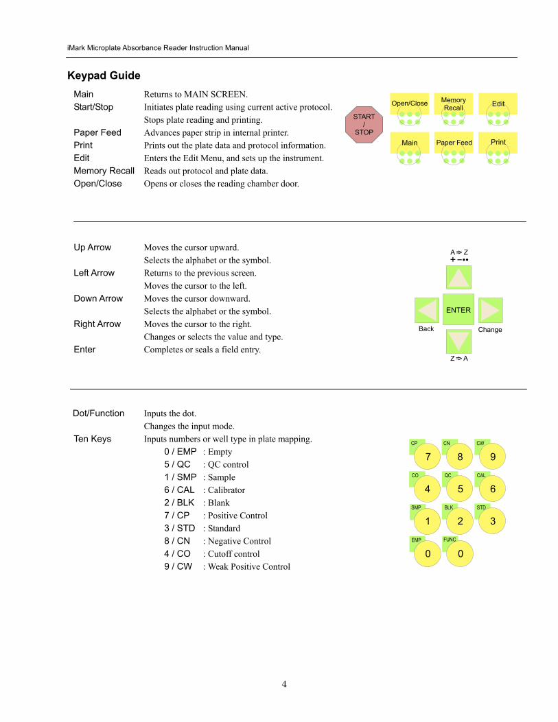
iMark Microplate Absorbance Reader Instruction Manual
5
Instrument Setup Unpacking the Instrument The shipping carton contains the following items
bull iMarktrade Microplate Reader with 415 nm 450 nm 490 nm 595 nm 655 nm and 750 nm interference filters installed on the filter wheel
bull Power cord
bull USB cable
bull Dust cover
bull Instruction manual
bull Warranty card
bull One roll of thermal printer paper
Inspect the exterior of the instrument for any signs of shipping damage Contact your local Bio-Rad representative if any of these items are damaged or missing
Initial Instrument Startup 1 Place the instrument on a clean sturdy table or bench It is important to keep the instrument in a clean
relatively dust free environment to ensure optimal performance
2 Connect the power cord to the back of the instrument Before connecting the instrument to the main electrical supply check that the AC voltage is appropriate for the instrument
3 To turn the power on press the green power button on the top of the instrument The LCD will display the version number of the on-board firmware After about three seconds the instrument will perform an initial self-diagnosis that requires about fifteen seconds The login screen displays for you to choose your user level (administrator or common user) and enter the password (initial password 00000) Please allow three minutes for the instrument to warm up (reach thermal equilibrium) before reading plates
Change password Select ldquoChange Passwordrdquo in the Security Menu
Enter the current Password then move the cursor to the 3rd line and enter a new password Press Enter to complete the field entry The system will return to the previous Security Menu
Change user mode Select ldquoChange userrdquo in the Security Menu
Select a desired user mode by pressing the Right Arrow key Enter the appropriate password for the selected user mode Press Enter to complete the field entry The system will return to the previous Security Menu
System Login User Administrator Password Press ENTER
iMark Microplate Absorbance Reader Instruction Manual
6
4 Install the printer paper The thermal printer paper is printable on one side only and must be properly installed for the printer to function The outside of the roll is the printable side
a Open the rear cover of the instrument b Tear off a small piece at the beginning of a new roll at an angle to form
a point c Place the roll of paper in the small pan-like holder positioned below
the printer The roll should be positioned so that it will feed from the bottom
d While pressing the PAPER FEED key feed the pointed end of the paper into the paper feed slot in the underside of the printer until the printer grabs the paper and feeds it through the slot in the top of the instrument
e Securely close the rear compartment
Multi-language support The iMark LCD can produce text in three languages English Russian and Chinese To switch to English from Russian or Chinese press the Main button then the Edit button to get to the configuration screen Press the downward-pointing arrow on the key pad six times to navigate to the language options line Press Enter twice to select English and then press Enter a third time to shut down the reader When restarted the iMark will display in English
Instrument Shutdown To shut down the instrument press the green power button on the top of the instrument for a few seconds Then the LCD will display a Power off Yes or No screen Select ldquoYesrdquo to shut down the instrument
Power off gtgtYes No
iMark Microplate Absorbance Reader Instruction Manual
7
Software Overview Capabilities The iMark Microplate Reader has on-board software that allows the user to set the plate reading and data analysis conditions to save these settings as a test protocol to read a microplate under this protocol and to print reports from the built-in printer The software communicates through the 4-line 20-character LCD and is controlled through the instruments membrane keypad
The software has three different protocol types End-point analysis Kinetic analysis and Checkmark validation The Checkmark validation function is used only by the administrator to verify quality control
The display shows the current mode The user can choose between these protocol types or can press the Memory Recall key to use the current protocol type
Quick Guide to Reading a Plate 1 Turn on the instrument Allow about 30 seconds for self-diagnosis The instrument needs to warm up for
about three minutes prior to reading a plate
2 Upon power up the login screen will appear Enter the login password (initial password 00000) press Enter
3 Program a protocol for your assay See page 22 for information on Editing a Kinetic protocol or page 25 for Editing an End Point Protocol Make sure filters installed correlate with information entered in reader firmware
4 Select the protocol of choice if programmed See the Memory Recall section on page 21 for detailed operation
5 Review or print parameters set in the protocol See the Editing End Point Protocol section on page 25 for details
6 Verify settings on Cutoff Report Limit STDs Mode Mapping and kit name parameters are as desired
7 Protocol setting can be printed see the Printing Reports and Protocols section on page 20 for information
8 All reports other than the raw data report require plate mapping Set the plate map with instructions from the Plate Map Setting Procedure section on page 33
9 The Matrix and Limit reports require assignment of upper and lower limits Set the upper and lower limits in the Editing End Point Protocol Limit setting window
10 The Cutoff report requires definition of the cutoff setting Refer to the Cutoff Setting Procedure section on page 26
11 The Curve fit and Concentration reports require that standard concentration and locations must be defined Refer to page 29 for details on how to define the standards and the curve fit parameters
12 Set the general reading mode (single or dual wavelength reading plate shaking read mode) following the instructions in the Mode Setting Procedure section on page 32
After warm-up is complete
13 Press the ldquoMainrdquo key The main screen appears on the LCD
14 Carefully place the microplate in the reading chamber Press the ldquoStartStoprdquo key to read
iMark Microplate Absorbance Reader Instruction Manual
8
Instrument Functions Calculations The Microplate Reader uses Beers Law to calculate the absorbance value of each well Beers Law states that absorbance is equal to the log10 of the ratio of the baseline measurement intensity (Io) to the sample measurement intensity (I)
Beers Law Absorbance = Log10 (IoI)
Before measuring the plate the reader takes a reading for all eight photodiode channels These values are recorded as the baseline measurement (Io) values for each channel respectively The reader then records the sample measurement (I) value for each well and calculates the absorbance using these values Channel-to-channel error is significantly reduced because the Io value for a given channel is used only in determining the absorbance of the wells of that channel
Security password The iMark Microplate Reader requires a user login with password This security feature helps to prevent any unwarranted modifications to the analysis conditionsprotocols and data stored in the instrument and identifies the operator on reports The reader has two user settings the Administrator and the Common user Each user level has its own security password
Memory Back-Up The battery back-up provides memory even after the reader is turned off
The following information will be saved in the memory until new reading parameters are set by the user or a new plate is read by the instrument Note that if a run is aborted before it is finished all the previous plate reading data remain in memory and none of the data from the aborted reading is stored
bull The ten latest sets of End-point protocol plate reading results
bull The two latest sets of Kinetic plate reading results (max 30 series of readings for each Kinetic Protocol)
bull 64 End-point Protocol settings and 2 Kinetic Protocol settings
bull A set of Checkmark reference data and the one latest set of Checkmark reading result
bull A set of standard curve data for the storage of standard curves and graphs
bull Eight wavelength values for filters
bull Laboratory name
bull Two security passwords (for the Administrator and the Common user)
bull Instrument serial number
In addition to the battery back-up memory the instrument has a small amount of non-volatile memory to keep the system information after the battery is dead The serial number is stored in this memory The average battery life is 5 years
iMark Microplate Absorbance Reader Instruction Manual
9
The first time the instrument is turned on or after a battery failure the following default information is held in the memory
1 Both Administrator and Common user security passwords are set to 00000
2 Laboratory name is Bio-Rad Laboratories
3 All wavelength values of the filters are set to --- nm
4 The date and time of the calendar chip are set to 1 day 1 month 00 year 0 hour and 0 minute
5 No plate reading data is available
6 End-point protocol is chosen and the protocol number is set to 1
7 No standard curve data for the storage of standard curves and graphs is available
Limits The Microplate Reader displays absorbance readings with absolute values as 3500 Out-of-range absorbance values (those with absolute values greater than 3500) are displayed as either or - For example if the absorbance is 4500 then the display will read and if the absorbance is -4500 the display will read -
iMark Microplate Absorbance Reader Instruction Manual
10
Report Types Two types of reports can be generated End-point protocol and Kinetic protocol Each of these and their subtypes are described below After these descriptions there are flow diagrams that show how to access specific choices
End-point Protocol Reports Nine types of End-Point Protocol reports can be generated raw data absorbance limit matrix cutoff curve fit concentration difference and TeSeE screening reports
1 Raw data report The Raw data report is the uncorrected absorbance values (without blank subtraction) In single-wavelength mode the reported value is the measured absorbance In dual-wavelength mode the reported value is the difference between the uncorrected readings taken with the measurement filter and with the reference filter
2 Absorbance report The Absorbance report is the blank-corrected absorbance values The mean absorbance value of all of the wells designated as assay blanks is calculated and then subtracted from all 96 values of the raw data set to produce the Absorbance report
Abs = Raw ndash Blank mean
Blank mean = Xn
SD = [X^2 ndash n(Blank mean)^2n-1]^12
Where
SD = Standard deviation
X = Sum total of the raw absorbance for each blank
X^2 = Sum total of the squared raw absorbance for each blank
n = Number of blanks
3 Limit report The Limit report provides a qualitative YESNO report Wells with blank-subtracted absorbance values between the upper and lower limits are represented with an asterisk () wells with absorbance values below the lower limit by minus signs (-) and wells with absorbance values greater than the upper limit by positive signs (+)
4 Matrix report The Matrix report provides a qualitative report of the relative magnitude of the absorbance values on the plate The absorbance range defined by the upper and lower limits is divided into 10 equal partitions numbered 0 through 9 The blank-subtracted absorbance value of each well is classified according to the partition of the matrix to which it corresponds and is reported as a signal digit Wells with absorbance values greater than the upper limit are reported by plus signs (+) and wells with absorbance values less than the lower limit by minus signs (-)
iMark Microplate Absorbance Reader Instruction Manual
11
5 Cutoff report The Cutoff report provides a qualitative report of the relative magnitude of the absorbance values or converted concentrations on the plate
Four types of cutoff reports are supported ranged constant single constant formula and ratio These and their subtypes are listed below
a Ranged Constant The user inputs Positive and Negative values to be used as the cutoff
For units designated Abs if the absorbance of a well is within the positive and negative cutoff values the well is scored If the absorbance of a well is greater than the positive value the well is scored + and if the absorbance of a well is below the negative value the well is scored -
For units not designated Abs the absorbance value of each well is converted to the concentration value using the curve fit constants of the curve fit report If the concentration of a well is within the positive and negative cutoff values the well is scored If the concentration of a well is greater than the positive value the well is scored + and if the concentration of a well is below the negative value the well is scored -
b Single Constant The user inputs Positive and Gray zone values to be used as the cutoff
For units designated Abs if the absorbance of a well is within the gray zone value of the positive cutoff value the well is scored If the absorbance of a well is more than the gray zone value and greater than the positive value the well is scored + and if the absorbance of a well is more than the gray zone value below the positive value the well is scored -
Upper cutoff absorbance = Positive absorbance + ((Gray zone100) Positive absorbance)
Lower cutoff absorbance = Positive absorbance ndash ((Gray zone100) Positive absorbance)
For units not designated Abs the absorbance value of each well is converted to the concentration value using the curve fit constants of the curve fit report If the concentration of a well is within the gray zone value of the positive cutoff value the well is scored If the concentration of a well is more than the gray zone value greater than the positive value the well is scored + and if the concentration of a well is more than the gray zone value below the positive value the well is scored -
Upper cutoff conc = Conc of positive controls + ((Gray zone100) Conc of positive controls)
Lower cutoff conc = Conc of positive controls - ((Gray zone100) Conc of positive controls)
c Formula The mean absorbance values of the Positive and Negative wells defined in the plate map are used for the cutoff formula calculation
The 12 types of formula-based cutoff reports are
i k CNx vii k + CNx
ii k CPx viii k + CPx
iii k COx ix k + COx
iv CNx k x kCNx + CPx
v CPx k xi xi (CNx + CPx) k
vi COx k xii k1CNx + k2CPx
iMark Microplate Absorbance Reader Instruction Manual
12
The result absorbance value of the formula calculation and the gray zone value that is entered by the user are used for the cutoff
The upper and lower cutoff values are
Upper cutoff absorbance = Result of a Formula + ((Gray zone100) Result of a Formula)
Lower cutoff absorbance = Result of a Formula - ((Gray zone100) Result of a Formula)
The absorbance range of the upper and lower cutoff is divided into 10 equal partitions numbered 0 through 9 The absorbance value of each well is classified according to the partition of the matrix to which it corresponds and is reported as a signal digit Wells with absorbance values greater than the upper cutoff are reported by plus signs (+) and wells with absorbance values less than the lower cutoff by minus signs (-)
d Ratio The mean absorbance value of the Calibrator wells defined in the plate map and the concentration value entered by the user are used for the cutoff ratio Before the cutoff the absorbance value of each well is converted into the concentration value The ratio of ConcentrationAbsorbance of Calibrator is applied to the conversion Then the cutoff is done with the defined Positive and Negative or the defined Positive and Gray zone values
6 Curve Fit Report The Curve fit report provides a regression analysis based on the absorbance values of a series of standards There are ten types of curve fits supported with the onboard software on iMark Microplate readers
i 5P Logistic Rodbard ii 4P Logistic Rodbard iii 5P Logistic Cook-Wilkenson iv 4P Logistic Cook-Wilkenson v 5P Exponential vi Sigmoid Logistic vii Linear regression viii Quadratic regression ix Cubic x Point-To-Point regression
The onboard software calculates the best fit of the defined curve between each set of two consecutive data points in the standard curve of absorbance vs concentration And then it generates the report with the coefficients of regression the correlation coefficient and the standard error
For readers with the optional internal printer or with an external ESCP printer which accepts ESCP code a graph of the standard curve may be generated when selected in the report parameter
7 Concentration Report In case of the curve fit the Concentration report also provides the regression analysis After the calculation of the curve fit it calculates the concentrations values of the samples and generates the report
In case of the cutoff constant with the unit not designated Abs and in case of the cutoff ratio the reader generates the list of concentration of each well
8 Difference Report The Difference report is the subtraction report between the neighboring columns or row
iMark Microplate Absorbance Reader Instruction Manual
13
9 TeSeE Screening Report Analysis of the TeSeE screening assay results can be done with two pre-programmed protocols ldquoTeSeErdquo protocol is stored in Endpoint Protocol position 5 and ldquoTeSeE eqrdquo is stored in Endpoint Protocol position 6 as factory default setting Both protocols are locked
TeSeE screening report is generated only if these protocols are selected as current active protocol Plate is first validated according to negative and positive controls validation criteria samples are then compared to the calculated cut-off
Criteria for plate validation are set as follows
Criteria 1 Individual Negative Control must be lt 0150
Number of valid Negative Control must be gt= 3
Criteria 2 Individual Negative Control must be lt 1400 Negative Control average
Number of valid Negative Control must be gt= 2
Criteria 3 Positive Control average must be gt= 1000
Cutoff is calculated as follows
TeSeE
Positive cutoff = Negative Control average + 0210
Negative cutoff = (Negative Control average + 0210) 0900
TeSeE eq
Positive cutoff = Negative Control average + 0210
Negative cutoff = Negative Control average + 0090
Samples are interpreted as follows
ldquoPOSrdquo Positive when sample OD gt= Positive cutoff
ldquoNEGrdquo Negative when sample OD lt Negative cutoff
ldquordquo Gray zone NEG cutoff =lt sample OD lt POS cutoff
iMark Microplate Absorbance Reader Instruction Manual
14
Protocol
Security
Filters
Date Set
Lab name
Cutoff
Report
Limit
STDs
Mode
Mapping
Kit name
Not Used
Constant
Control
Formula
Ratio
Ranged Cutoff Single Cutoff
Ranged Cutoff Single Cutoff
12 choices of cutoff formula
Concentration
Unit
Cutoff value
Cutoff Values setting Gray zone setting when single cutoff
Cutoff Control setting Gray zone setting when single cutoff
Coefficient setting of selected formula
0 - 9999
17 choices of unit
Cutoff Values setting Gray zone setting when single Cutoff
Ranged Cutoff Single Cutoff
Raw(Raw data) Abs(Absorbance) Lim(Limit) Mtx(Matrix) Cut(Cutoff) Crv(Curve fit) Cnc(Concentration) Dif(Difference)
Upper Limit Lower Limit For Limit Report
Standard information
Curvefit
Number of STD Concentration
Unit
Curvefit type Graph axis
Set Photo mode Set Shaking
Set Read mode
Manual mapping
Automatic mapping
Change password
Change user
End-point Analysis Protocol
Up to 12 Standards 0 to 9999 17 choices
12 choices of curve fit type 4 choices of graph axis combination of Log and Linear
SingleDual Wavelength Shake (Yes No) Speed (High Low Mid) Time Read Speed (FastStep) and Read Mode (NormalEval)
Func key to switch [N] to [F] [N] for sample number [F] for sample
Func key to switch from [ABC] to [abc] to [sym] key to move cursor
For current user mode Administrator or common user Administrator has power to switch
Filter wavelength setting for 1-8 positions ldquo0rdquo for no filter
DayMonthYear HourMin
Func key to switch from [ABC] to [abc] to [sym] key to move cursor
Save STDC
Language
Save STD Curve
Rename STD Curve
Select Language
5 choices of storage number
5 choices of STD curve
Func key to switch from [ABC] to [abc] to [sym] key to move cursor
Choices of pre-installed language for LCD and report printout
BlankCNCWCPCOQCCalibratorSampleReplicate well
Recall Setting Select STD Curv
Recall YesNo Selection 5 choices of memorized STD curve
Edit
Bold for menu pages
LCD adj and key to change contrast
Italic for program pages
iMark Microplate Absorbance Reader Instruction Manual
15
Kinetic Protocol Reports Four types of Kinetic protocol reports can be generated absorbance kinetic plots linear regression and GALT reports
1 Absorbance Report The Kinetic Absorbance report is the series of absorbance data in the kinetic sequence
2 Kinetic Plots Report The Kinetic plots are the absorbance plots of each well in the plate It is available for readers with the optional internal printer or with an external ESCP printer which accepts ESCP code
3 Linear Regression Report The Linear Regression report provides the calculation of Kinetic reaction rate for each well using the linear regression
4 GALT Report The GALT report calculates the following formula for each well between two readings of a plate
GALT = (R2 ndash R1) k
Where R1 = Absorbance value of 1st reading
R2 = Absorbance value of 2nd reading
k = GALT factor
iMark Microplate Absorbance Reader Instruction Manual
16
Func key to switch from [ABC] to [abc] to [sym] key to move cursor
Func key to switch from [ABC] to [abc] to [sym] key to move cursor
Func key to switch from [ABC] to [abc] to [sym] key to move cursor
DayMonthYear HourMin
Filter wavelength setting for 1-8 positions ldquo0rdquo for no filter
Edit
Kinetic Analysis Protocol
Protocol
Security
Filters
Date Set
Lab Name
Change password
Change user
LockUnlock
Mode
Report
Calc
Mapping
Assay
Kit name
Reading Inter
Shaking Phmode
Speed
Number of reads (2-30) start delay time (0-999) Reading interval time Shake (FirstEverydisable) Speed (High Low Mid) Time Single Dual wavelength Read Speed (FastStep)
CC Limit (correlation coefficient limit) Calcrange (calculation range of reading number) for Linear regression Report
GALT factor k input (0- 9999) Result = (2nd read ndash 1st read)k for GALT Report
Manual mapping
Automatic mapping
Func key to switch [N] to [F] [N] for sample number [F] for sample type
General Kinetic or GALT assay assay type selection
Absorbance KINETIC Plots Linear regression when General Kinetic Assay selected GALT report when GALT Kinetic assay selected
For current user mode Administrator or Common user Administrator has power to switch
Special Buttons
Memory Recall
Main
Protocol Plate Data
Report Protocol
End point Kinetic
Checkmark
1-64 End point protocol storage 1-2 Kinetic protocol storage Checkmark reader test
Printout
Returns to MAIN screen
SaveSTDC
Language
BlankCNCWCPCOQCCalibratorSampleReplicate well
Save STD Curve
Rename STD Curve
Select Language
5 choices of storage number
5 choices of STD curve
Choices of pre-installed language for LCD and report printout
Bold for menu pages
LCD adj and key to change contrast
Italic for program pages
iMark Microplate Absorbance Reader Instruction Manual
17
Screen by Screen Procedures Initial Startup
01Kinetic-1 M405(1)R605(6)30read Shake999sMidEvery 382402 180901
End point mode
Kinetic mode
Self-diagnosis iMark Microplate Reader 1305 180901
System Login User Administrator Password Press ENTER
Login SCREEN
01EndPoint Assay01 M405(1)R655(6) Shake999sMid 382402 180901
Checkmark Validation Program
180901
Checkmark mode
Initializing reader
MAIN SCREEN
Self-Diagnosis This screen will appear upon power-up and during self-diagnosis Date and time are also indicated on this screen
Initialization After self-diagnosis the system initializes all the hardware
Security Check The system requires a password to confirm that the user is the authorized operator Pressing the ChangeRight arrow key will switch the user mode between Common user and Administrator Password for both Common user and Administrator is set as ldquo00000rdquo upon factory shipment Operator can change the password in the EDIT menu See Security
System Ready When this MAIN screen is on the LCD the StartStop key can be pressed for microplate reading Pressing StartStop key will begin reading with the current protocol There are three kinds of MAIN screens depending on the current protocol type Endpoint Kinetic and Checkmark program The four arrow keys Numeral keys Main key and Enter key are inactive StartStop Memory Recall Edit Print and Paper Feed keys are active
01EndPoint Assay01 M405(1)R655(6) Shake999sMid
180901
Kit name for current active protocol
01Kinetic-1 M405(1)R605(6)30read Shake999sMidEvery 382402 180901
Kinetic M Measurement wavelength and its position in the filter disk R Reference wavelength and its position in the filter disk Number of reading for KINETIC
Storage number in memory of current active protocol
Plate shaking parameters period in seconds and speed
M Measurement wavelength and its position in the filter disk R Reference wavelength and its position in the filter disk
Date (day month year)
Plate shaking parameters Period in seconds Speed (fast middle slow) Mode (before every read before first read and no shake)
End point
iMark Microplate Absorbance Reader Instruction Manual
18
Configuring the System NOTE To return to the previous screen use the backleft arrow key
Edit Menu
Security function raquoChange Password bullChange user bullLockUnlock Prtl
Change Password
LockUnlock
Change user
Change Password Current New Common user
Security for current active Protocol [Lock] Unlock
System Login User Administrator Password Press ENTER
Change Password Select ldquoChange Passwordrdquo in the Security Menu Enter the current password then move the cursor to the 3rd line and enter a new password Press Enter to complete the field entry The system will return to the previous Security Menu Change User Mode Select ldquoChange userrdquo in the Security Menu Select a desired user mode by pressing the Right Arrow key Enter the appropriate Password for the selected user mode Press Enter to complete the field entry The system will return to the previous Security Menu LockUnlock Protocol Select ldquoLockUnlock Prtlrdquo in the Security Menu Move the selected mark ldquo[ ]rdquo to the desired position Lock or Unlock using the Right Arrow key Press Enter to complete the field entry The system will return to the previous Security Menu If ldquoLockrdquo is selected the current active protocol will be protected against modification made by a Common user If ldquoUnlockrdquo is selected the current active protocol can be modified by any user mode NOTE Only the Administrator has authority to lock and unlock the Checkmark Protocol
Edit Menu This menu can be accessed by pressing the Edit key in the MAIN SCREEN
Security Menu Security Setting Select ldquoSecurityrdquo in the Edit Menu screen and press Enter The Security Menu appears on the screen
raquoProtocol Labname Security SaveSTDC Filters Language Date set LCD adj
iMark Microplate Absorbance Reader Instruction Manual
19
1400nm 5650nm 2450nm 6nm 3475nm 7nm 4650nm 8nm
Filter
DayMonthYear 16 05 01 Hour Minutes 18 55
Date set
Enter Lab name Bio Rad Laboratories uarr [ABC]
Lab name
Filter Setting Move the cursor to the desired position by using the Up Down and Right arrow keys Enter the filter wavelength on the selected position using the number keys If the selected position of the filter disk is empty enter three ldquordquo Press Enter to complete the field entry The system will return to the previous Edit Menu screen
Calendar Setting Move the cursor to the desirable position for date or time input by using the Up Down and Right arrow keys Enter the present date or time using the number keys Press Enter to complete the field entry The system will return to the previous Edit Menu screen
Lab Name Setting Use the Up and Down arrow keys to select from ldquoArdquo to ldquoZrdquo and symbols Use the Number keys for numeric input Use the Right arrow key to move the cursor to the right Use the Left arrow key to return the cursor to the Edit Menu screen Pressing the FUNCrdquo key will toggle the character mode between Upper case alphabet Lower case alphabet and symbol The current character mode is indicated on the lower right corner of the LCD
Save STD Curve gt Save STD Curve Rename STD Curve
Save STDC Save STDC Setting Select ldquoSave STDCrdquo in Edit Menu screen above and press Enter The Save STD Curve Menu appears on the screen Move the cursor to the desired position by using the Up and Down arrow keys
Select STD storage gt 1120304 1500 2 3150304 1030
Select for renaming gt 1160304 1125 2 3150304 1030
Save STD Curve To save a STD Curve select the storage number between 1 and 5 Use the Up and Down arrow keys to move the cursor to the desired storage number and press Enter to complete the selection After the storage number selection the rdquoAre you surerdquo message appears Select ldquoYesrdquo or ldquoNordquo and press Enter In case of ldquoYesrdquo the reader saves the STD Curve and returns to the Edit Menu screen If the curve fit calculation is not done or has not finished successfully an error message will appear and the STD Curve will not be saved STD curve does not
exist yet Press any key
Save STD Curve 1160304 1125 Are you sure gt Yes No
Rename STD Curve To change a name of an STD Curve select a storage number between 1 and 5 Use the Up and Down arrow keys to move the cursor to the desired storage number and press Enter to complete the selection Use the Up and Down arrow keys to select from ldquoArdquo to ldquoZrdquo and symbol Use the Number keys for numeric input Use the Right arrow key to move the cursor to the right Use the Left arrow key to return the cursor to the Edit Menu screen Pressing the FUNCrdquo key will toggle the character mode between Upper case alphabet Lower case alphabet and symbol The current character mode is indicated on the lower right corner of the LCD
1160304 1125 gtSTD Curve 1 lt
[ABC]
Save STD Curve
Rename STD Curve
iMark Microplate Absorbance Reader Instruction Manual
20
Printing Reports and Protocol information
Print menu raquoReports bullProtocol
Print Menu Print Menu Access this menu screen by pressing the Print key in the MAIN screen Printing Reports Select ldquoReportsrdquo and press Enter to print the current active plate data report Printing Protocol Information Select ldquoProtocolrdquo and press Enter to print all parameter settings in the current active protocol Stop Printing Press the StartStop key during printing to stop the print job immediately When printing is completed the system automatically returns to the MAIN screen
Select Language raquoEnglish bull bull bull
Language Changing Language Select a desired language using the Up and Down arrow keys and press Enter to complete the selection The system will generate a message for an immediate power off to restart Select ldquoYesrdquo and press Enter to activate the selected new language The newly-changed language will be applied to the LCD screen and printed reports Power off
gtgtYes No
LCD Contrast 12345678901234567890
laquo 26 raquo ENTER to complete
Adjusting LCD Contrast Adjust LCD contrast by using the Right and Left arrow keys and press Enter to complete the adjustment
LCD adj
iMark Microplate Absorbance Reader Instruction Manual
21
Memory Recall Operation
01 200500 1400 02raquo210500 1700 03 200500 1800 darr04raquo200500 1900
01raquo200500 0900 02raquo200500 1000
Memory Recall raquoProtocol bullPlate Data
Protocol type menu
Data type menu
End Point
Kinetic
End Point
Kinetic
Memory Recall Menu
Select protocol type raquoEnd Point
bullKinetic bullCheckmark
Select Protocol 02 uarrraquo Protocol -2 Protocol -3 darr Protocol -4
Select Protocol 01 raquo Kinetic -1 GALT
Select data type raquoEnd Point
bullKinetic bullCheckmark
200501 0900
Checkmark
Checkmark program has been activated Press any key
Checkmark
Selecting Protocol Move the cursor to the position of the desired protocol and press Enter to complete the selection NOTE ldquordquo indicates the currently activated protocol and ldquordquo indicates a security locked protocol There is no protocol selection with ldquoCheckmarkrdquo When a protocol is selected the system will then automatically return to the MAIN screen
Changing Current Active Protocol Select ldquoProtocolrdquo in Memory Recall menu above and press Enter The Select Protocol type menu will appear on the screen Select a protocol using the Up and Down arrow keys Press Enter to complete the selection
Selecting Plate Data Move the cursor to the position of the desired plate data and press Enter to complete the selection NOTE ldquordquo indicates the currently activated plate data There is only one storage for ldquoCheckmarkrdquo data When plate data is selected the system automatically returns to the MAIN screen
Changing Current Active Plate Data Select ldquoPlate Datardquo using the Memory Recall button and press Enter The Data type menu will appear Use the Up and Down arrow keys to select a plate data type Press Enter to complete the selection
This menu screen can be accessed by pressing the Memory Recall key in the MAIN screen
iMark Microplate Absorbance Reader Instruction Manual
22
Editing the Kinetic Protocol
Select ldquoProtocolrdquo in the Edit Menu and press Enter The Kinetic Protocol menu will appear on the screen if the current active protocol type is Kinetic
Reading speed [Fast mode] Step mode
Speed
raquoReading Speed Inter Shaking Phmode
Kinetic Mode
Kinetic Protocol Menu
raquoMode Report Calc Kit name Mapping Assay
This menu screen can be accessed by selecting ldquoModerdquo in the Kinetic Protocol menu above
Number of Reading = 20 (2-30) Start Delay time = 25 sec(0-999)
Reading
Number of Reading = 2 Start Delay time = 25 sec(0-999)
Number of Readings and Start Delay Time Setting Press the Up or Down arrow key to change the number Enter the appropriate numbers with the numeral keys and press Enter to complete the field entry The system will return to the Kinetic Edit Menu If GALT is the current assay type the number of reading fields is fixed at 2 Press the StartStop key to set the Start Delay time enter a value and press Enter until the reading starts
1-gt2raquo 100 sec 2-gt3 100 sec 3-gt4 100 sec darr4-gt5 100 sec
Inter Use same interval between all reads
raquoYes No
Setting Reading Intervals The system prompts the operator to set a reading interval before each plate run Move the cursor to the desired selection ldquoYesrdquo or ldquoNordquo and press Enter The system generates the interval entry screen Move to the active entry field by pressing the Up and Down arrow keys and enter appropriate numbers using numeral keys Press Enter to complete all field entries The system will return to the Kinetic Mode menu
Photometric Dual Measurement405 nm Reference 655 nm
Ph mode Photometric Mode Setting When the ldquoPhotometricrdquo field is activated pressing the Right arrow key will switch the field entry ldquoSinglerdquo lt-gtrdquoDualrdquo Pressing the Up or Down arrow keys will move the cursor to the next entry field Pressing the Right arrow key when the wavelength field is activated will change the wavelength to the next available selection installed in the reader Press Enter to complete all field entries
Shaking parameters Before Every read Speed Mid Time 999 sec
Shaking Plate Shake Parameters When the ldquoBeforerdquo field is activated pressing the Right arrow key will change the field entry ldquoEveryrdquo-gtrdquo--rdquo-gtrdquoFirstrdquo-gt When the ldquoSpeedrdquo field is activated pressing the Right arrow key will change the field entry ldquoMidrdquo -gtrdquoHirdquo-gtrdquoLowrdquo-gt When the ldquoTimerdquo field is activated enter the time value for plate shaking period using the numeral keys Press Enter to complete all field entries
Selecting Reading Speed Use the Up or Down arrow keys to switch the selection Press Enter to complete the selection
Edit Menu raquoProtocol Labname Security bullSaveSTDC Filters bullPrinter Date set
This menu screen can be accessed by pressing the Edit key in the MAIN screen
iMark Microplate Absorbance Reader Instruction Manual
23
Kit name for 01 raquoGAP TEST IgGlaquo uarr [ABC]
Kit name
Calculation
Mapping
Assay
Assay type selection raquo[General KINETIC] GALT assay
Calculation Param CC Limit 0910
Calcrange 10 - 20
Select Mapping mode raquoManual mapping bullAutomatic mapping
raquo[Linregression] bullAbsorbance bullKINETIC Plots
Report
Plate Mapping See Plate Map setting procedure
Result = (R2 ndash R1)k k = 999999 R11st Reading R22nd Reading
If GALT
Setting the Kit Name Use the Up and Down arrow keys to select alphabet from ldquoArdquo to ldquoZrdquo and space Use the Number keys for numeric input Use the Right arrow key to move the cursor to the right Use the Left arrow key to return to the Protocol Menu screen Pressing ldquoFUNCrdquo key will change the character mode Upper case alphabet -gt Lower case alphabet -gt symbol The current character mode is indicated on the lower right corner of the LCD
Kinetic Protocol Menu
Selecting Kinetic Assay Type Move the cursor to the desired Assay type by pressing the Up or Down arrow keys Press Enter to complete the selection The item with mark ldquo[ ]rdquo is the currently selected item GALT assay Result = factor x (2nd Read ndash 1st Read)
Selecting Report Type Move the cursor to the desired report type by pressing the Up or Down arrow keys Pressing the Right arrow key will select or deselect the item Press Enter to complete the selection Note When GALT assay is selected ldquoGALT reportrdquo shall be the only one option on this screen
raquoMode bullReport bullCalc bullKit name bullMapping bullAssay
Calculation Parameter Setting When the ldquoCC Limitrdquo field is activated pressing the numeral key will enter the desired numbers Press Enter to complete all field entries If the GALT Reports is activated pressing the numeral keys will enter the desired numbers Press Enter to complete all field entries
iMark Microplate Absorbance Reader Instruction Manual
24
Checkmark Value Setting (Administrator only)
raquoSerial Report bullLinearity ref bullMaxCV bullFilter Check ref
Checkmark Protocol Menu
raquoSerial 0000 Reptype Simple
405nm S10158 Linearity S20309 reference S31401 S42109
MaxCV raquoS115 Linearity S205 reference S302 S402
Filter max min 4051875 0329 4501167 0954 darr 4920596 0103
Serial Report
Linearity reference
Max CV
Filter check reference
Filter max min uarr 5401875 0329 6201167 0954 6900596 0103
Setting the Serial Number and Report Type Pressing the Up and Down arrow keys will move the cursor and change the field entry When ldquoSerial rdquo field is active enter the serial number that will be shown in the data sheet of the Checkmark plate using the numeral keys When the ldquoRep typerdquo field is active pressing the Right arrow key will switch the report type between ldquoSimplerdquo and ldquoFullrdquo
Setting the Linearity Reference Value Pressing the Up or Down arrow keys will move the field entry from S1 to S4 Pressing the Right arrow key will change the wavelength 405 nm-gt450 nm-gt492 nm-gt540 nm-gt620 nm-gt690 nm Use the numeral keys for the reference value setting Pressing Enter will complete all field entries at all wavelength
Max CV setting Pressing the Up or Down arrow keys will move the field entry from S1 to S4 Use the numeral keys for the Max CV setting Press Enter to complete all field entries
Setting the Filter Check Reference Value Initial screen shows the reference entries for 405 nm to 492 nm and pressing the Down arrow key at the bottom of the screen entries will scroll to the next page for 540 nm to 690 nm Pressing the Up Down and Right arrow keys will move the field entry Use the numeral keys for the filter check reference value setting Press Enter to complete all field entries
Select ldquoProtocolrdquo in the Edit Menu and press Enter The Checkmark Protocol Menu will appear on the screen if the current active protocol type is Checkmark mode
Edit Menu raquoProtocol bullLabname bullSecurity bullSaveSTDC bullFilters bullPrinter bullDate set
This menu screen can be accessed by pressing the Edit key in the MAIN screen
iMark Microplate Absorbance Reader Instruction Manual
25
Editing End Point Protocol
Upper Limit= 2000 Lower Limit= 0000 input range 0ndash3500 Upper gt Lower
Standard menu raquoSTD information
bullCurvefit bullRecall STD Curve
raquoCutoff bullMode bullReport bullMapping bullLimit bullKit name bullSTDs
Cutoff
See Plate Map setting procedure
See Standard setting procedure
See Mode setting procedure
raquo[Not use] bullRatio bullConstant bullContrl bullFormula
raquoSet photo mode bullSet shaking bullSet read mode
Select mapping mode raquoManual mapping bullAutomatic mapping
Mapping
Mode
Report
STDs
Limit
Kit name for 01 raquoGAP TEST IgGlaquo uarr [ABC]
Kit name See Kit name setting in Editing Kinetic Protocol
See Cutoff setting procedure
Select ldquoProtocolrdquo in Edit Menu screen above and press Enter The End point Protocol Menu will appear on the screen if the current active protocol type is End point mode
End Point Protocol Menu
raquo[Raw] bullMtx bullCnc bullAbs bullCut bullDif bullLim bullCrv
If ldquoDifrdquo selected
[Raw] bullMtx bullCncbullAbs bullCut [Dif] bullLim bullCrv raquorow odd-even
Seting the Report Type Use the Up and Down Arrow key to move the cursor and press the Right Arrow key to select or deselect the report type Selected report type is marked as ldquo[ ]rdquo Press Enter to complete the selection
Setting the Limit Value Use the Up and Down Arrow key to move the cursor and enter the OD value using the numeral keys The OD value range is 0000 - 3500 Press Enter to complete the selection
Edit Menu raquoProtocol bullLabname bullSecurity bullSaveSTDC bullFilters bullPrinter bullDate set
This menu screen can be accessed by pressing the Edit key in the MAIN screen
iMark Microplate Absorbance Reader Instruction Manual
26
Cutoff Setting Procedure
Cutoff Setting Menu This menu is entered by choosing Cutoff in the End Point Protocol Menu It is used to set the cutoff type The cutoff type marked with ldquo[ ]rdquo is the current selection The Up and Down arrow keys move the cursor to the desired item in the menu list When the desired parameters have been selected press Enter twice to accept the selection and to continue to the next screen Not use means that the reader does not generate the cutoff report Four types of cutoff are supported
1 Cutoff Constant 2 Cutoff Control 3 Cutoff Formula 4 Cutoff Ratio
a Cutoff Constant
Selection of SingleRanged Cutoff Constant This menu selects Single or Ranged cutoff type The cutoff type marked with ldquo[ ]rdquo is the current selection The Enter key seals the selection and resumes to the next setting screen
Single Cutoff Constant The Numerical keys and the Decimal point key are used to enter the positive and gray zone values The Right arrow key is used to select the unit The Up and Down arrow keys move the cursor to the desired parameter of the single cutoff The Enter key sets all values and selection of the cutoff constant and returns the user to the previous screen Ranged Cutoff Constant The Numerical keys and the Decimal point key are used to enter the positive and negative values The Right arrow key is used to select the unit The Up and Down arrow key moves the cursor to the desired ranged cutoff parameters The Enter key sets all values and selection of the cutoff constant and returns to the previous screen NOTE Two available Cutoff constants are ldquoAbsorbancerdquo and ldquoConcentrationrdquo If Abs is chosen the Absorbance cutoff will be done with the cutoff constant parameters defined and the absorbance report is generated For other units defined in the curve fit setting the Concentration value using the curve fit and then cutoff is done with the cutoff constant parameters defined and the concentration value of each well It is necessary to set the curve fit parameters
raquoNot usex bullRatio [Const] bullContrl bullFormula
raquoPositive gt= 9999 Gray zone 50 Unit moll
raquoPositive gt= 9999 Negative lt 1999 NegativeltPositive Unit moll
raquoRanged cutoff [Single cutoff]
Single cutoff
Ranged
iMark Microplate Absorbance Reader Instruction Manual
27
b Cutoff Control
Selection of SingleRanged Cutoff Control This menu screen selects Single or Ranged cutoff type The cutoff type marked with ldquo[ ]rdquo is the current selection The Enter key seals the selection and resumes to the next setting screen
Single Cutoff Control The Numerical keys are used to enter the gray zone value The unit is fixed to Abs The Enter key sets the value of the cutoff control and returns to the previous screen Ranged Cutoff Control There is no parameter to set for the ranged cutoff control The Enter key returns to the previous screen NOTE CNx is the mean absorbance value of Negative control wells and CPx is the mean absorbance value of Positive control wells These wells are defined in the plate map setting The cutoff is done with the Positive and Negative value to the absorbance value of each well
c Cutoff Formula
Selection of Formula This menu screen selects a formula for cutoff calculation The formula marked with ldquo[ ]rdquo is the current selection The Up and Down arrow keys move the cursor to the desired formula type The movement of the cursor follows the scroll of this screen The Enter key marks the selection and advances the user to the next setting screen The supported formula types are
1 k CNx 2 k CPx 3 k COx 4 CNx k 5 CPx k 6 COx k 7 k + CNx 8 k + CPx 9 k + COx 10 kCNx + CPx 11 ( CNx + CPx ) k 12 k1CNx + k2CPx
Coefficient for Cutoff Formula 1 to 11 The Numerical keys and the Decimal point key are used to enter the coefficient k and gray zone values The Up and Down arrow key moves the cursor to the desired parameter of the cutoff formula The Enter key sets all values of the cutoff formula and returns to the previous screen
Positive gt= CNx Gray zone 50 Unit Abs
Positive gt= CPx Negative lt CNx Unit Abs
Enter key to accept
raquoRanged cutoff [Single cutoff]
Single cutoff
Ranged
Input coefficient k = 001 (001-10) Gray zone 50(0-99)
k CNx k CPx k COx CNx k CPx k COx k k + CNx k + CPx k + COx k CNx + CPx (CNx + CPx) k
uarr raquoCNx k bullCPx k bullCOx k darr bullk + CNx
Select formula raquo[kCNx ] bullkCPx darr bullkCOx
uarr raquok + CPx bullk + COx bullkCNx + CPx darr bull(CNx + CPx) k
uarr raquok1CNx + k2CPx
Page-1
Page-2
Page-3
Page-4
iMark Microplate Absorbance Reader Instruction Manual
28
Coefficient for Cutoff Formula 12 The Numerical keys and the Decimal point key are used to enter the coefficient k1 and k2 and gray zone values The Up and Down arrow key moves the cursor to the desired cutoff formula The Enter key sets the all values of the cutoff formula and returns to the previous screen NOTE CNx is the mean absorbance value of Negative control wells CPx is the mean absorbance value of Positive control wells and COx is the mean absorbance value of Cutoff control wells These wells are defined on the plate map setting The cutoff value is calculated using the defined formula with the defined values and coefficients
d Cutoff Ratio
Ratio to Calibrator In this screen there are three items for setting the ratio to calibrator The Up and Down arrow key moves the cursor to the desired item in the menu list The Enter key seals the selection and resumes to the next setting screen
Concentration of Calibrator The Numerical keys and the Decimal point key are used to enter the calibrator concentration value The Enter key sets the value and returns to the previous screen Unit of Calibrator Seventeen standard units are supported The unit marked with ldquo[ ]rdquo is the current selection The setting procedure is the same as the unit selection of Standards Cutoff Value Setting This menu screen selects Single or Ranged cutoff type The cutoff type marked with ldquo[ ]rdquo is the current selection The Enter key marks the selection and continues to the next setting screen Single Cutoff Control The Numerical keys are used to enter the Positive cutoff concentration value and gray zone value The Enter key sets these cutoff ratio values and returns to the previous screen Ranged Cutoff Control The Numerical keys are used to input the Positive and the Negative cutoff concentration values The Enter key sets these cutoff ratios and returns to the previous screen NOTE The calibrator concentration value is used to convert the absorbance value of each well into a concentration value The ratio of ConcentrationAbsorbance of Calibrator well is applied to the conversion The cutoff uses defined Positive and Negative values to the converted concentration value of each well
Input coefficient k1 = 001 (001-10) k2 = 100 (001-10) Gray zone 50(0-99)
k1 CNx + k2 CPx
Ratio to Calibrator raquoConcentration bullUnit bullCutoff value
Concentration 9999 unit moll
uarrraquo 01 ugdl 02 ngml 03[ pgml] darr 04 pmml
raquoPositive gt= 9999 Gray zone 50
Unit moll
raquoPositive gt= 9999 Negative lt 9999 NegativeltPositive
Unit moll
raquoRanged cutoff [Single cutoff]
Concentration
Unit
Cutoff value
Single cutoff
Ranged cutoff
iMark Microplate Absorbance Reader Instruction Manual
29
Standard Setting Procedure
Standard Curve Setting Menu This menu screen is entered by choosing STDs in the End Point Protocol Menu screen It is used to set the concentration data and the curve fit type for a standard curve or to recall a memorized standard curve The Up and Down arrow key moves the cursor to the desired item in the menu list The Enter key seals the selection and continues to the next setting screen
a STD Information Setting
STD Information In this screen there are three items for setting the concentration data of standards The Up and Down arrow keys move the cursor to the desired item in the menu list The Enter key seals the selection and continues to the next setting screen
Number of Standards The Numerical keys are used to enter the number of standards ldquo0rdquo means that the curve fit report is not used The Enter key sets the number and returns to the previous screen The maximum number of standards is 12 Concentration The Numerical keys and the Decimal point key are used to enter the concentration values of standards The Up and Down arrow keys move the cursor to the desired position The movement of the cursor also follows the scroll of this screen The Enter key sets all values of the concentration of standards and returns to the previous screen Unit Seventeen units are supported The unit marked with ldquo[ ]rdquo is the current selection The Up and Down arrow keys move the cursor to the desired unit type The movement of the cursor also follows the scroll of this screen Press Enter twice to select the unit type and to return to the previous screen The supported types of unit are
1 moll 11 pgml 2 m moll 12 Uml 3 u moll 13 IUml 4 n moll 14 uIUml 5 p moll 15 mIUml 6 mgl 16 EU 7 ngl 17 Arbit 8 pgl 9 ugdl 10 ngml
STD information raquoNumber of STD bullConcentration bullUnit
STD 1 0512 STD 2 1012 STD 3 1512 darr STD 4 2053
Standard menu raquoSTD information bullCurve fit bullRecall STD curve
Concentration
Number of STD
Number of STD = 05 (0 2ndash12)
uarrraquo 01 ugdl 02 ngml 03[ pgml] darr 04 pmml
Unit
iMark Microplate Absorbance Reader Instruction Manual
30
b Curve Fit Setting
Curve Fit In this screen there are two choices to set the curve fit The Up and Down arrow keys move the cursor to the desired item in the menu list The Enter key seals the selection and resumes to the next setting screen
Curve Fit Type 10 types of curve fit are supported as below The curve fit type marked with ldquo[ ]rdquo is the current selection The Up and Down arrow key moves the cursor to the desired curve fit type The movement of the cursor follows the scroll of this screen Press Enter twice to select the unit type and to return to the previous screen The supported curve fit types are
1 5P Logistic Rodbard 2 4P Logistic Rodbard 3 5P Logistic Cook-Wilkenson 4 4P Logistic Cook-Wilkenson 5 5P Exponential 6 Sigmoid Logistic 7 Linear regression 8 Quadratic regression 9 Cubic 10 Point To Point regression
Graph Axis Four types of graph are supported The curve fit type marked with ldquo[ ]rdquo is the current selection The Up and Down arrow keys move the cursor to the desired graph type Press Enter twice to select the unit type and to return to the previous screen The supported graph types are
1 Log - Log 2 Log - Linear 3 Linear - Log 4 Linear - Linear
uarr 5p logisticRodb raquo 4p logisticRodb [5p logisticCook] darr 4p logisticCook
raquo X-Log Y-Log [X-Log Y-Lin] X-Lin Y-Log X-Lin Y-Lin
Curve fit type
Graph axis
Curve fit setting raquoCurve fit type bullGraph axis
iMark Microplate Absorbance Reader Instruction Manual
31
c Recall STD Curve Setting
Recall Setting of Standard Curve In this screen there are two items for setting the Recall STD curve as below The Up and Down arrow keys move the cursor to the desired item in the menu list
1 Recall setting (YesNo) 2 Selecting the storage number of standard curves (1 -gt 5)
Recall Setting Move the cursor to the desired position using the Up Down or Right arrow keys Enter key accepts the setting and returns the user to the standard menu screen
Yes Recalling of the standard curve is active No Recalling of the standard curve is inactive
Storage Number Selection Five memories are selectable The vacant memory (marked with asterisks on the date and time field) is also selectable It is necessary to save a standard curve before using its protocol Move the cursor to the desired position using the Up and Down keys This setting screen consists of two parts The Right arrow key is used to switch the indication field between the date and time to the standard curve name Move the cursor to the desired position using the Up and Down keys The Enter key accepts the storage number and returns to the standard menu screen NOTE If the recall of standard curve is active (the recall setting is ldquoYesrdquo) the standard information setting and the curve fit setting will be invalidated and their setting screens will not open
Recall STD curve raquoRecall setting bullSelect STD curve
Recall setting raquoYes No
Recall setting
Select STD Curve raquo1160304 1125
2 darr 3150304 1030
Select STD Curve uarrraquo4
5
Select STD Curve raquo1 STD Curve 1
2 STD Curve 2 darr 3 STD Curve 3
Select STD Curve uarrraquo4 STD Curve 4
5 STD Curve 5
Select STD curve
Right arrow key
iMark Microplate Absorbance Reader Instruction Manual
32
Mode Setting Procedure
Mode Setting Menu This menu screen is entered by choosing the Mode in the End Point Protocol Menu screen or the Kinetic Protocol Menu screen It is used to set the plate reading conditions The Up and Down arrow keys move the cursor to the desired item in the menu list The Enter key seals the selection and resumes to the next setting screen
a Set Photo Mode
Photo Mode In this screen the user chooses Single or Dual wavelength measurement and assigns the measurement and reference (for dual wavelength measurement) filters The assignment of the reference filter appears for dual wavelength measurement The Up and Down arrow keys move the cursor to the desired parameter The Right arrow key chooses SingleDual wavelength measurement and selects the installed filter on the Filters of Edit Menu screen The Enter key seals the selection and returns to the previous screen
b Set Shaking
Shaking In this screen the user selectsdeselects shaking function sets the shaking strength and enters the shaking time A shaking time of 0s indicates no shaking The maximum shaking time is 999 seconds The Up and Down arrow key moves the cursor to the desired parameters The Right arrow key toggles between YesNo (SelectDeselect) shaking or selects strength LowMiddleHigh The Numerical keys are used to enter the shaking time The Enter key seals the selection and returns the user to the previous screen
c Set Read Mode
Read Mode In this screen the user chooses Fast or Step reading and also chooses Normal or Evaluation mode The ldquo[ ]rdquoindicates the current selection The Up and Down arrow key moves the cursor to the desired parameters The Right arrow key chooses FastStep speed or chooses NormalEval mode The Enter key seals the selection and returns to the previous screen The followings are the description of each read mode parameter Reading speed
Fast reading 6 secsingle wavelength reading 10 secdual wavelength reading
Step reading 15 secsingle wavelength reading 30 secdual wavelength reading
Reading mode
Normal mode Plate reading once Evaluation mode Four plate readings per one of measurement are performed and
the average data of their plate readings is generated as a plate data
Photometric Dual Measurement400 nm Reference 655 nm
Set Shake parameters ShakeYes SpeedMid Time 199sec(0-999)
raquoReading speed [Fast ] Step bullRead mode [Normal] Eval
raquoSet Photo mode bullSet shaking bullSet read mode
Photometric Single Measurement400 nm
iMark Microplate Absorbance Reader Instruction Manual
33
Plate Map Setting Procedure
Select Mapping Mode Menu This menu screen is entered by choosing Mapping in the End Point Protocol Menu screen or the Kinetic Protocol Menu screen It is used to map the plate format The Up and Down arrow keys move the cursor next to the desired item of menu list The Enter key seals the selection and changes this screen to the next setting screen
a Manual Mapping
Manual Mapping In this screen the user can set the plate format manually Ten well types can be set Well types The supported well types are
Well type Indication on LCD
1 Blank B 2 Sample X00hellipX99 3 Standard S01hellipS99 4 In-kit Control Positive Control CP0hellipCP9 5 Weak Positive Control CW0hellipCW9 6 Negative Control CN0hellipCN9 7 Cutoff Control CO0hellipCO9 8 Calibrator CL0hellipCL9 9 QC Control QC0hellipQC9 10 Empty well -
The key assignments of well type are ldquo0EMPrdquo Empty well ldquo5QCrdquo Quality Control well ldquo1SMPrdquo Sample well ldquo6CALrdquo Calibrator well ldquo2BLKrdquo Blank well ldquo7CPrdquo Positive Control well ldquo3STDrdquo Standard well ldquo8CNrdquo Negative Control well ldquo4COrdquo Cutoff Control well ldquo9CWrdquo Weak Positive Control well
Two Edit Modes in Plate Mapping There are two editing modes for well type input mode and for well number input The current input mode is displayed at the upper left corner of the screen When using the well type input mode the mode sign is ldquo[F]rdquo When using the well number input mode the mode sign is ldquoNrdquo The cursor that encloses the editing position of well has two types of enclosures depending on the mode For example ldquo[S01]rdquo accepts the well type keys that be assigned to the numerical keys and ldquoS01rdquo accepts the numerical input The mode is easily changed with the Decimal point key Key Functions The Up Down Right and Left arrow keys move the cursor to the desired well The movement of the cursor follows the scroll of this screen The Left arrow key will return the screen to the preceding screen or the select Mapping mode Menu only if the cursor is on column 1 At this time the selection screen appears (see the left figure) The Decimal point key changes the input mode The Numerical keys have two functions one to input the number and another to select a well type The Enter key checks the consistency between the edited plate map and other parameters memorizes the plate map into the protocol and changes this screen back to the preceding screen If it finds any inconsistency a warning message will appear on the screen
Select Mapping mode raquoManual mapping bullAutomatic mapping
N 1 2 3 4 A B CN1 S01 S01 B B CN1 S02 S02 C B CN2 S03 S03 [F] 5 6 7 8 A X11 X12 X13 X14 B X21 X22 X23 X24 C X31 X32 X33[X34]
Discard change 1Yes 2No Press 1 or 2 key
iMark Microplate Absorbance Reader Instruction Manual
34
Acceptable Number Ranges for each well type 1 Blank and Empty wells do not use numbers 2 Sample and Standard wells 00 - 99 3 Standard wells 01 - 99 4 Control and Calibrator wells 0 - 9
b Automatic Mapping
Automatic Mapping The user can input the number of each well type in this screen These defined numbers are used to set a plate map automatically Well type Nine well types are available
1 BLK Blank (0-gt10) 2 CN Control CN (0-gt9) 3 CW Control CW (0-gt9) 4 CP Control CP (0-gt9) 5 CO Control CO (0-gt9) 6 QC Control QC (0-gt9) 7 CAL Calibrator (0-gt9) 8 SMP Sample (0-gt96) 9 REP Replicate well (1-gt4)
It is possible to define the number of blanks samples calibrators and controls But the number of Standards is not included because standards are defined at the Standard Setting Menu The number of replicate wells is also included It is used for replicating each well type individually Key Functions The Up Down Right and Left arrow keys are used to move the cursor to the next position The Numerical keys are used to input the mapping parameters The Enter key accepts the mapping parameters and sets a plate map automatically using these parameters During the execution of the plate mapping the Plate auto-mapping completed message appears on the screen After that the user returns automatically to the previous Protocol Menu screen If the Left arrow key is pressed at the left end position of the cursor the left figure will appear on the screen If the user chooses Yes the system will return to the previous Protocol Menu screen If the user chooses No the system will stay in this setting screen Assigning Order and Direction of plate mapping Assigning Order The order of blanks standards samples calibrators and controls are fixed as follows Numbering for standards samples calibrators and controls is started at 1
1 Blank 2 Standard 1 -gt12 ---- NOTE 3 Control CN 1-gt9 4 Control CW 1-gt9 5 Control CP 1-gt9 6 Control CO 1-gt9 7 Control QC 1-gt9 8 Calibrator 1-gt9 9 Sample 1-gt96 10 Empty well NOTE If ldquoCutoff Controlrdquo ldquoValue by Formulardquo or ldquoRatio to Calibratorrdquo is
selected for the Cutoff plate mapping skips arranging the standards Assigning Direction The placing direction of the mapping is limited to the column direction as below
Column direction A1 -gt H1 A2 -gt H2 ----- A12 -gt H12
Discard change 1Yes 2No Press 1 or 2 key
Automatic mapping BLK= 1 CP = 1 CAL= 0 CN = 1 CO = 0 SMP=93 CW = 0 QC = 0 REP= 1
Plate auto-mapping completed
iMark Microplate Absorbance Reader Instruction Manual
35
Warning and Error of Automatic Mapping Warning screen If the total number of wells mapped exceeds 96 wells a warning message in the left figure appears on the screen The calculation of the total number of mapping wells is as follows
(Blanks+Standards+CNs+CWs+CPs+COs+QCs+Calibrators+Sample)Replicates The plate mapping is executed normally and the exceeded part is invalidated Error screen If one or more mapping parameters are over the input range an error message in the left figure will appear on the screen On the third line of the LCD the name of the parameter which is out of range and its input range will appear
Example ldquoBLK 0 ndash 10rdquo In case there is more than one error the first parameter of errors is indicated By pressing any key the user returns to the automatic mapping screen Example of automatic mapping An example of automatic mapping is as below 1 Conditions of each parameter
Blank = 1 Standard = 8 Control CN = 2 CW = 0 CP = 2 CO = 0 QC = 0 Calibrator = 1 Sample = 32 Replicate number = 2
2 Plate mapping data
1 2 3 4 5 6 7 8 9 10 11 12 A B C D E F G H
B B S1 S1 S2 S2 S3 S3
S4 S4 S5 S5 S6 S6 S7 S7
S8 S8 CN1 CN1 CN2 CN2 CP1 CP1
CP2 CP2 CL1 CL1 X1 X1 X2 X2
X3 X3 X4 X4 X5 X5 X6 X6
X7 X7 X8 X8 X9 X9 X10 X10
X11 X11 X12 X12 X13 X13 X14 X14
X15 X15 X16 X16 X17 X17 X18 X18
X19 X19 X20 X20 X21 X21 X22 X22
X23 X23 X24 X24 X25 X25 X26 X26
X27 X27 X28 X28 X29 X29 X30 X30
X31 X31 X32 X32 E E E E
Warning The total Of mapped wells has Exceeded 96 Press any key
Entered value is Out of range BLK 0 ndash 10 Press any key
iMark Microplate Absorbance Reader Instruction Manual
36
Instrument Maintenance
Caution Electrical shock hazard Always disconnect the instrument from the AC power source before opening the service compartment
Caution The lamp and the lamp cover may be very hot Use caution and allow the lamp to cool
before attempting service
Installing Interference Filters 1 With the power off open the rear cover of the instrument by pressing the
release latch located on the top left portion of the cover 2 Locate the filter wheel on the left side of the instrument Note that the
filter wheel has eight filter positions 3 Rotate the filter wheel to the desired filter Grasp the top of filter frame
and pull up to remove the filter 4 Insert the new filter into the desired filter position 5 Ensure that the new filter is added to the filter list as follows Main
menu-gtEdit-gtFilters
Changing the Lamp 1 With the power off open the rear cover of the instrument by pressing the
release latch located on the top left portion of the cover 2 Remove the two screws on the black plastic cover and carefully remove
the plastic cover 3 Remove the screw on the metal cover Lift the cover up and away from
the instrument This will allow the lamp to be pulled free from the lamp housing
4 Holding the ceramic base in one hand and the lamp housing in the other carefully pull the lamp free of the base
5 Carefully insert the new lamp firmly in the ceramic base Apply even pressure when inserting the lamp so that the bulb dose not become misaligned in the reflector housing Be extremely careful not to touch the front glass of the lamp during installation
6 Position the new lamp into the housing so that the plastic guides hold the flange of the lamp
7 Carefully place the metal cover over the lamp Tighten the screw 8 Replace the plastic cover and tighten the screws 9 Close the rear cover
iMark Microplate Absorbance Reader Instruction Manual
37
Troubleshooting and Error Messages
The iMark Microplate Reader constantly monitors several functions and displays appropriate messages on the LCD as errors are encountered
Error Recommendation
LCD appears blank on power up
a Power is not turned on The AC outlet is non-functional
b Unit is not plugged into AC outlet or power code is not attached to the instrument
Check power cord connections at outlet and on the rear panel of the instrument
1
c The AC outlet is non-functional Check circuit breakers or fuses
Instrument displays ldquoLight bulb errorrdquo message indicating that the bulb is burned out
Check whether lamp is emitting light
a Lamp is not emitting light Replace the lamp as described in x
2
b Lamp is emitting light Check the alignment of the lamp in the housing Align or replace the lamp if necessary
Printer will not print on command
3
a Printer paper is not installed properly Verify that the paper is properly installed Refer to x for details
Plate carriage jams during reading and ldquoPlate carrier errorrdquo is displayed
a Plate is not seated in carriage properly Press the STOP button immediately Position the plate carefully in the carriage making certain that it is properly seated
4
b Plate height is exceeding 16mm Use Microplate which is less than 16mm in height
5 LCD displays ldquoFilter missingrdquo Install a filter in the empty position Select the installed filter by pressing Edit key
6 LCD displays ldquoFilter disk jammedrdquo indicating that the filter wheel is not turning freely
Turn off the instrument and inspect the filter wheel Turn by hand to verify that the wheel is moving freely Make sure all the filters are properly installed and firmly seated Contact your Bio-Rad representative if the filter wheel is jammed or if the problem persists
7 LCD displays ldquoFilter not installedrdquo Enter the Edit Menu by pressing Edit key and set up the filters
iMark Microplate Absorbance Reader Instruction Manual
38
Wells have color but absorbance values seem low
a Incorrect filter used for measurement andor reference wavelength
Check wavelength used in analysis Read plate in single wavelength mode at all wavelength to verify that the proper filter was used The measurement wavelength should produce the highest absorbance
b The best measurement wavelength filter for the substrate in use has not been installed in the filter wheel
Check references for the substrate you are using or determine the best measurement wavelength by analyzing the substrate product on a scanning spectrophotometer Custom filters are available from 400 to 750 nm
8
c The filters have been switched in the wheel Check that the filters are installed in the correct position
9 ldquoPrinter errorrdquo displayed Check for paper jam Install the printer paper correctly
10 ldquoBattery errorrdquo displayed The internal battery is almost dead Contact your local Bio-Rad office
11 The following messages are displayed ldquoMemory errorrdquo ldquoCalendar errorrdquo ldquoLCD hardware errorrdquo ldquoPrinter errorrdquo ldquoLight level errorrdquo ldquoDA conversion errorrdquo ldquoAD conversion errorrdquo ldquoEEPROM errorrdquo ldquoUSB errorrdquo
Contact your local Bio-Rad office if these problems persist
iMark Microplate Absorbance Reader Instruction Manual
39
Instrument Specifications Computer interface USB 20
Plate shaking 3 speeds (low mid high) Programmable time period 0 - 999 seconds
Data storage The most recent 10 data plates for end-point most recent 2 data plates of 30 readings for kinetic readings protocol data and calendarclock function shall be kept in memory by a lithium battery even when the power is off Average lifetime of the battery shall be 5 years
Warm-up time 3 minutes
Photometric Methods Single and dual wavelength
Photo detectors 8 silicon photodiodes for measurement and 1 silicon photodiode for reference
Light source Tungsten halogen lamp 20W with 3000 hours average lifetime
Spectral range 400 nm to 750 nm
Interference filters Wavelength tolerance plusmn30 nm Band width 10 nm typically
Filter capacity 8 filters
Reading speed Fast Reading 6 sec with single wavelength reading 10 sec with dual wavelength reading
Step Reading 15 sec with single wavelength reading 25 sec with dual wavelength reading
These times are minimum interval times between repetitive reads using onboard KINETIC protocol
Indication range 0000 to 35 OD
Resolution 0001 OD
Accuracy plusmn10 or 0010 from 0 to 30 OD at 490 nm
Linearity plusmn10 from 0 to 20 OD plusmn20 from 0 to 30 OD
Reproducibility 10 or 0005 OD from 0 to 20 OD 15 from 20 to 30 OD
Inter-channel variability 15 or 0005 OD from 0 to 30 OD
Stability and Drift 0010 OD at OD=1 with single wavelength reading
Built-in Printer Thermal printer Paper width 80mm
Line Voltage Universal input 100 - 240 VAC 5060Hz
Power consumption (max) 100 VA max
Dimensions (W x D x H 346 mm x 377 mm x 164 m mm
Weight 55 kg
Operating Environment 15ordmC - 40ordmC up to 90 relative humidity without condensation
Storage Temperature 10ordmC - 50ordmC up to 90 relative humidity without condensation
Life ScienceGroup
07-0816 0108 Sig 120710013301i Rev A USEG
Bio-RadLaboratories Inc
Web site wwwbio-radcom USA 800 4BIORAD Australia 61 02 9914 2800 Austria 01 877 89 01 Belgium 09 385 55 11 Brazil 55 21 3237 9400 Canada 905 364 3435 China 86 21 6426 0808 Czech Republic 420 241 430 532 Denmark 44 52 10 00 Finland 09 804 22 00 France 01 47 95 69 65Germany 089 318 84 0 Greece 30 210 777 4396 Hong Kong 852 2789 3300 Hungary 36 1 455 8800 India 91 124 4029300 Israel 03 963 6050 Italy 39 02 216091 Japan 03 6361 7000 Korea 82 2 3473 4460 Mexico 52 555 488 7670 The Netherlands 0318 540666 New Zealand 0508 805 500 Norway 23 38 41 30 Poland 48 22 331 99 99 Portugal 351 21 472 7700 Russia 7 495 721 14 04 Singapore 65 6415 3188 South Africa 27 861 246 723 Spain 34 91 590 5200 Sweden 08 555 12700 Switzerland 061 717 95 55 Taiwan 886 2 2578 7189 United Kingdom 020 8328 2000
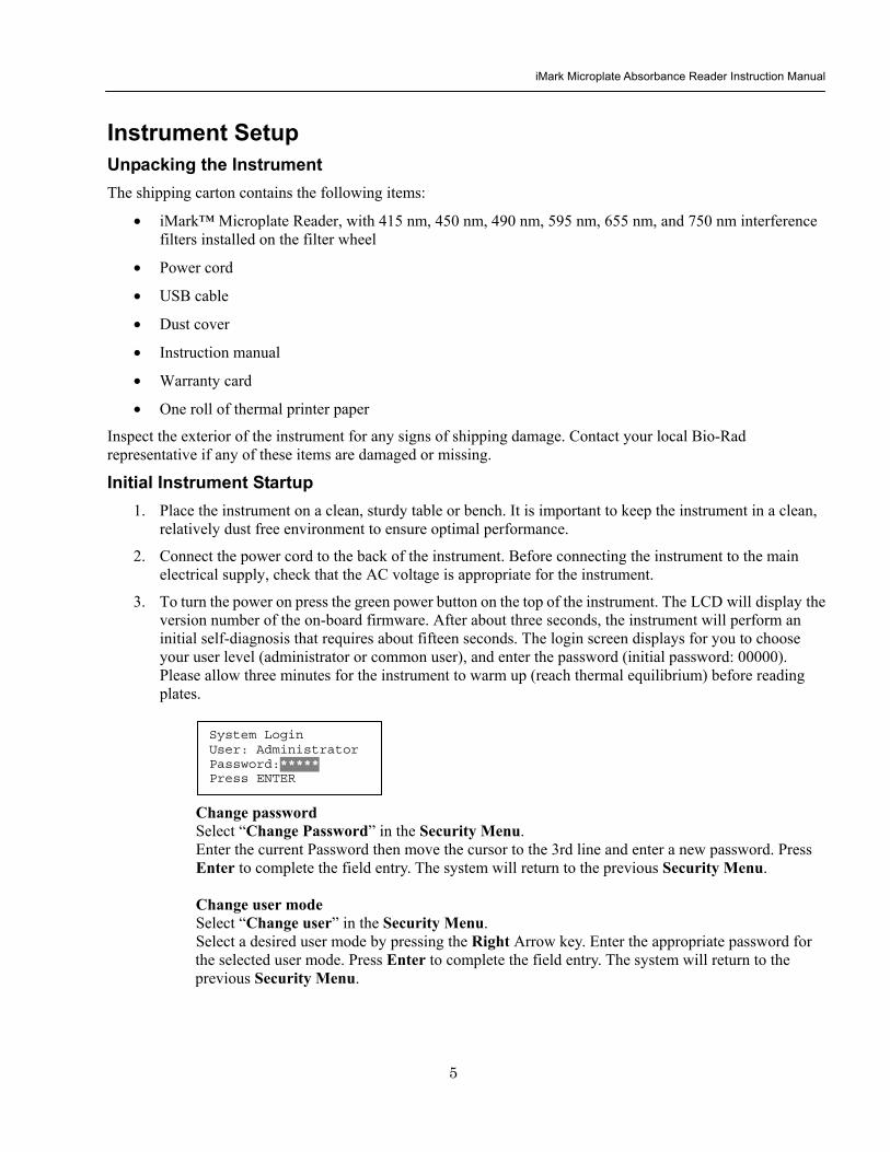
iMark Microplate Absorbance Reader Instruction Manual
6
4 Install the printer paper The thermal printer paper is printable on one side only and must be properly installed for the printer to function The outside of the roll is the printable side
a Open the rear cover of the instrument b Tear off a small piece at the beginning of a new roll at an angle to form
a point c Place the roll of paper in the small pan-like holder positioned below
the printer The roll should be positioned so that it will feed from the bottom
d While pressing the PAPER FEED key feed the pointed end of the paper into the paper feed slot in the underside of the printer until the printer grabs the paper and feeds it through the slot in the top of the instrument
e Securely close the rear compartment
Multi-language support The iMark LCD can produce text in three languages English Russian and Chinese To switch to English from Russian or Chinese press the Main button then the Edit button to get to the configuration screen Press the downward-pointing arrow on the key pad six times to navigate to the language options line Press Enter twice to select English and then press Enter a third time to shut down the reader When restarted the iMark will display in English
Instrument Shutdown To shut down the instrument press the green power button on the top of the instrument for a few seconds Then the LCD will display a Power off Yes or No screen Select ldquoYesrdquo to shut down the instrument
Power off gtgtYes No
iMark Microplate Absorbance Reader Instruction Manual
7
Software Overview Capabilities The iMark Microplate Reader has on-board software that allows the user to set the plate reading and data analysis conditions to save these settings as a test protocol to read a microplate under this protocol and to print reports from the built-in printer The software communicates through the 4-line 20-character LCD and is controlled through the instruments membrane keypad
The software has three different protocol types End-point analysis Kinetic analysis and Checkmark validation The Checkmark validation function is used only by the administrator to verify quality control
The display shows the current mode The user can choose between these protocol types or can press the Memory Recall key to use the current protocol type
Quick Guide to Reading a Plate 1 Turn on the instrument Allow about 30 seconds for self-diagnosis The instrument needs to warm up for
about three minutes prior to reading a plate
2 Upon power up the login screen will appear Enter the login password (initial password 00000) press Enter
3 Program a protocol for your assay See page 22 for information on Editing a Kinetic protocol or page 25 for Editing an End Point Protocol Make sure filters installed correlate with information entered in reader firmware
4 Select the protocol of choice if programmed See the Memory Recall section on page 21 for detailed operation
5 Review or print parameters set in the protocol See the Editing End Point Protocol section on page 25 for details
6 Verify settings on Cutoff Report Limit STDs Mode Mapping and kit name parameters are as desired
7 Protocol setting can be printed see the Printing Reports and Protocols section on page 20 for information
8 All reports other than the raw data report require plate mapping Set the plate map with instructions from the Plate Map Setting Procedure section on page 33
9 The Matrix and Limit reports require assignment of upper and lower limits Set the upper and lower limits in the Editing End Point Protocol Limit setting window
10 The Cutoff report requires definition of the cutoff setting Refer to the Cutoff Setting Procedure section on page 26
11 The Curve fit and Concentration reports require that standard concentration and locations must be defined Refer to page 29 for details on how to define the standards and the curve fit parameters
12 Set the general reading mode (single or dual wavelength reading plate shaking read mode) following the instructions in the Mode Setting Procedure section on page 32
After warm-up is complete
13 Press the ldquoMainrdquo key The main screen appears on the LCD
14 Carefully place the microplate in the reading chamber Press the ldquoStartStoprdquo key to read
iMark Microplate Absorbance Reader Instruction Manual
8
Instrument Functions Calculations The Microplate Reader uses Beers Law to calculate the absorbance value of each well Beers Law states that absorbance is equal to the log10 of the ratio of the baseline measurement intensity (Io) to the sample measurement intensity (I)
Beers Law Absorbance = Log10 (IoI)
Before measuring the plate the reader takes a reading for all eight photodiode channels These values are recorded as the baseline measurement (Io) values for each channel respectively The reader then records the sample measurement (I) value for each well and calculates the absorbance using these values Channel-to-channel error is significantly reduced because the Io value for a given channel is used only in determining the absorbance of the wells of that channel
Security password The iMark Microplate Reader requires a user login with password This security feature helps to prevent any unwarranted modifications to the analysis conditionsprotocols and data stored in the instrument and identifies the operator on reports The reader has two user settings the Administrator and the Common user Each user level has its own security password
Memory Back-Up The battery back-up provides memory even after the reader is turned off
The following information will be saved in the memory until new reading parameters are set by the user or a new plate is read by the instrument Note that if a run is aborted before it is finished all the previous plate reading data remain in memory and none of the data from the aborted reading is stored
bull The ten latest sets of End-point protocol plate reading results
bull The two latest sets of Kinetic plate reading results (max 30 series of readings for each Kinetic Protocol)
bull 64 End-point Protocol settings and 2 Kinetic Protocol settings
bull A set of Checkmark reference data and the one latest set of Checkmark reading result
bull A set of standard curve data for the storage of standard curves and graphs
bull Eight wavelength values for filters
bull Laboratory name
bull Two security passwords (for the Administrator and the Common user)
bull Instrument serial number
In addition to the battery back-up memory the instrument has a small amount of non-volatile memory to keep the system information after the battery is dead The serial number is stored in this memory The average battery life is 5 years
iMark Microplate Absorbance Reader Instruction Manual
9
The first time the instrument is turned on or after a battery failure the following default information is held in the memory
1 Both Administrator and Common user security passwords are set to 00000
2 Laboratory name is Bio-Rad Laboratories
3 All wavelength values of the filters are set to --- nm
4 The date and time of the calendar chip are set to 1 day 1 month 00 year 0 hour and 0 minute
5 No plate reading data is available
6 End-point protocol is chosen and the protocol number is set to 1
7 No standard curve data for the storage of standard curves and graphs is available
Limits The Microplate Reader displays absorbance readings with absolute values as 3500 Out-of-range absorbance values (those with absolute values greater than 3500) are displayed as either or - For example if the absorbance is 4500 then the display will read and if the absorbance is -4500 the display will read -
iMark Microplate Absorbance Reader Instruction Manual
10
Report Types Two types of reports can be generated End-point protocol and Kinetic protocol Each of these and their subtypes are described below After these descriptions there are flow diagrams that show how to access specific choices
End-point Protocol Reports Nine types of End-Point Protocol reports can be generated raw data absorbance limit matrix cutoff curve fit concentration difference and TeSeE screening reports
1 Raw data report The Raw data report is the uncorrected absorbance values (without blank subtraction) In single-wavelength mode the reported value is the measured absorbance In dual-wavelength mode the reported value is the difference between the uncorrected readings taken with the measurement filter and with the reference filter
2 Absorbance report The Absorbance report is the blank-corrected absorbance values The mean absorbance value of all of the wells designated as assay blanks is calculated and then subtracted from all 96 values of the raw data set to produce the Absorbance report
Abs = Raw ndash Blank mean
Blank mean = Xn
SD = [X^2 ndash n(Blank mean)^2n-1]^12
Where
SD = Standard deviation
X = Sum total of the raw absorbance for each blank
X^2 = Sum total of the squared raw absorbance for each blank
n = Number of blanks
3 Limit report The Limit report provides a qualitative YESNO report Wells with blank-subtracted absorbance values between the upper and lower limits are represented with an asterisk () wells with absorbance values below the lower limit by minus signs (-) and wells with absorbance values greater than the upper limit by positive signs (+)
4 Matrix report The Matrix report provides a qualitative report of the relative magnitude of the absorbance values on the plate The absorbance range defined by the upper and lower limits is divided into 10 equal partitions numbered 0 through 9 The blank-subtracted absorbance value of each well is classified according to the partition of the matrix to which it corresponds and is reported as a signal digit Wells with absorbance values greater than the upper limit are reported by plus signs (+) and wells with absorbance values less than the lower limit by minus signs (-)
iMark Microplate Absorbance Reader Instruction Manual
11
5 Cutoff report The Cutoff report provides a qualitative report of the relative magnitude of the absorbance values or converted concentrations on the plate
Four types of cutoff reports are supported ranged constant single constant formula and ratio These and their subtypes are listed below
a Ranged Constant The user inputs Positive and Negative values to be used as the cutoff
For units designated Abs if the absorbance of a well is within the positive and negative cutoff values the well is scored If the absorbance of a well is greater than the positive value the well is scored + and if the absorbance of a well is below the negative value the well is scored -
For units not designated Abs the absorbance value of each well is converted to the concentration value using the curve fit constants of the curve fit report If the concentration of a well is within the positive and negative cutoff values the well is scored If the concentration of a well is greater than the positive value the well is scored + and if the concentration of a well is below the negative value the well is scored -
b Single Constant The user inputs Positive and Gray zone values to be used as the cutoff
For units designated Abs if the absorbance of a well is within the gray zone value of the positive cutoff value the well is scored If the absorbance of a well is more than the gray zone value and greater than the positive value the well is scored + and if the absorbance of a well is more than the gray zone value below the positive value the well is scored -
Upper cutoff absorbance = Positive absorbance + ((Gray zone100) Positive absorbance)
Lower cutoff absorbance = Positive absorbance ndash ((Gray zone100) Positive absorbance)
For units not designated Abs the absorbance value of each well is converted to the concentration value using the curve fit constants of the curve fit report If the concentration of a well is within the gray zone value of the positive cutoff value the well is scored If the concentration of a well is more than the gray zone value greater than the positive value the well is scored + and if the concentration of a well is more than the gray zone value below the positive value the well is scored -
Upper cutoff conc = Conc of positive controls + ((Gray zone100) Conc of positive controls)
Lower cutoff conc = Conc of positive controls - ((Gray zone100) Conc of positive controls)
c Formula The mean absorbance values of the Positive and Negative wells defined in the plate map are used for the cutoff formula calculation
The 12 types of formula-based cutoff reports are
i k CNx vii k + CNx
ii k CPx viii k + CPx
iii k COx ix k + COx
iv CNx k x kCNx + CPx
v CPx k xi xi (CNx + CPx) k
vi COx k xii k1CNx + k2CPx
iMark Microplate Absorbance Reader Instruction Manual
12
The result absorbance value of the formula calculation and the gray zone value that is entered by the user are used for the cutoff
The upper and lower cutoff values are
Upper cutoff absorbance = Result of a Formula + ((Gray zone100) Result of a Formula)
Lower cutoff absorbance = Result of a Formula - ((Gray zone100) Result of a Formula)
The absorbance range of the upper and lower cutoff is divided into 10 equal partitions numbered 0 through 9 The absorbance value of each well is classified according to the partition of the matrix to which it corresponds and is reported as a signal digit Wells with absorbance values greater than the upper cutoff are reported by plus signs (+) and wells with absorbance values less than the lower cutoff by minus signs (-)
d Ratio The mean absorbance value of the Calibrator wells defined in the plate map and the concentration value entered by the user are used for the cutoff ratio Before the cutoff the absorbance value of each well is converted into the concentration value The ratio of ConcentrationAbsorbance of Calibrator is applied to the conversion Then the cutoff is done with the defined Positive and Negative or the defined Positive and Gray zone values
6 Curve Fit Report The Curve fit report provides a regression analysis based on the absorbance values of a series of standards There are ten types of curve fits supported with the onboard software on iMark Microplate readers
i 5P Logistic Rodbard ii 4P Logistic Rodbard iii 5P Logistic Cook-Wilkenson iv 4P Logistic Cook-Wilkenson v 5P Exponential vi Sigmoid Logistic vii Linear regression viii Quadratic regression ix Cubic x Point-To-Point regression
The onboard software calculates the best fit of the defined curve between each set of two consecutive data points in the standard curve of absorbance vs concentration And then it generates the report with the coefficients of regression the correlation coefficient and the standard error
For readers with the optional internal printer or with an external ESCP printer which accepts ESCP code a graph of the standard curve may be generated when selected in the report parameter
7 Concentration Report In case of the curve fit the Concentration report also provides the regression analysis After the calculation of the curve fit it calculates the concentrations values of the samples and generates the report
In case of the cutoff constant with the unit not designated Abs and in case of the cutoff ratio the reader generates the list of concentration of each well
8 Difference Report The Difference report is the subtraction report between the neighboring columns or row
iMark Microplate Absorbance Reader Instruction Manual
13
9 TeSeE Screening Report Analysis of the TeSeE screening assay results can be done with two pre-programmed protocols ldquoTeSeErdquo protocol is stored in Endpoint Protocol position 5 and ldquoTeSeE eqrdquo is stored in Endpoint Protocol position 6 as factory default setting Both protocols are locked
TeSeE screening report is generated only if these protocols are selected as current active protocol Plate is first validated according to negative and positive controls validation criteria samples are then compared to the calculated cut-off
Criteria for plate validation are set as follows
Criteria 1 Individual Negative Control must be lt 0150
Number of valid Negative Control must be gt= 3
Criteria 2 Individual Negative Control must be lt 1400 Negative Control average
Number of valid Negative Control must be gt= 2
Criteria 3 Positive Control average must be gt= 1000
Cutoff is calculated as follows
TeSeE
Positive cutoff = Negative Control average + 0210
Negative cutoff = (Negative Control average + 0210) 0900
TeSeE eq
Positive cutoff = Negative Control average + 0210
Negative cutoff = Negative Control average + 0090
Samples are interpreted as follows
ldquoPOSrdquo Positive when sample OD gt= Positive cutoff
ldquoNEGrdquo Negative when sample OD lt Negative cutoff
ldquordquo Gray zone NEG cutoff =lt sample OD lt POS cutoff
iMark Microplate Absorbance Reader Instruction Manual
14
Protocol
Security
Filters
Date Set
Lab name
Cutoff
Report
Limit
STDs
Mode
Mapping
Kit name
Not Used
Constant
Control
Formula
Ratio
Ranged Cutoff Single Cutoff
Ranged Cutoff Single Cutoff
12 choices of cutoff formula
Concentration
Unit
Cutoff value
Cutoff Values setting Gray zone setting when single cutoff
Cutoff Control setting Gray zone setting when single cutoff
Coefficient setting of selected formula
0 - 9999
17 choices of unit
Cutoff Values setting Gray zone setting when single Cutoff
Ranged Cutoff Single Cutoff
Raw(Raw data) Abs(Absorbance) Lim(Limit) Mtx(Matrix) Cut(Cutoff) Crv(Curve fit) Cnc(Concentration) Dif(Difference)
Upper Limit Lower Limit For Limit Report
Standard information
Curvefit
Number of STD Concentration
Unit
Curvefit type Graph axis
Set Photo mode Set Shaking
Set Read mode
Manual mapping
Automatic mapping
Change password
Change user
End-point Analysis Protocol
Up to 12 Standards 0 to 9999 17 choices
12 choices of curve fit type 4 choices of graph axis combination of Log and Linear
SingleDual Wavelength Shake (Yes No) Speed (High Low Mid) Time Read Speed (FastStep) and Read Mode (NormalEval)
Func key to switch [N] to [F] [N] for sample number [F] for sample
Func key to switch from [ABC] to [abc] to [sym] key to move cursor
For current user mode Administrator or common user Administrator has power to switch
Filter wavelength setting for 1-8 positions ldquo0rdquo for no filter
DayMonthYear HourMin
Func key to switch from [ABC] to [abc] to [sym] key to move cursor
Save STDC
Language
Save STD Curve
Rename STD Curve
Select Language
5 choices of storage number
5 choices of STD curve
Func key to switch from [ABC] to [abc] to [sym] key to move cursor
Choices of pre-installed language for LCD and report printout
BlankCNCWCPCOQCCalibratorSampleReplicate well
Recall Setting Select STD Curv
Recall YesNo Selection 5 choices of memorized STD curve
Edit
Bold for menu pages
LCD adj and key to change contrast
Italic for program pages
iMark Microplate Absorbance Reader Instruction Manual
15
Kinetic Protocol Reports Four types of Kinetic protocol reports can be generated absorbance kinetic plots linear regression and GALT reports
1 Absorbance Report The Kinetic Absorbance report is the series of absorbance data in the kinetic sequence
2 Kinetic Plots Report The Kinetic plots are the absorbance plots of each well in the plate It is available for readers with the optional internal printer or with an external ESCP printer which accepts ESCP code
3 Linear Regression Report The Linear Regression report provides the calculation of Kinetic reaction rate for each well using the linear regression
4 GALT Report The GALT report calculates the following formula for each well between two readings of a plate
GALT = (R2 ndash R1) k
Where R1 = Absorbance value of 1st reading
R2 = Absorbance value of 2nd reading
k = GALT factor
iMark Microplate Absorbance Reader Instruction Manual
16
Func key to switch from [ABC] to [abc] to [sym] key to move cursor
Func key to switch from [ABC] to [abc] to [sym] key to move cursor
Func key to switch from [ABC] to [abc] to [sym] key to move cursor
DayMonthYear HourMin
Filter wavelength setting for 1-8 positions ldquo0rdquo for no filter
Edit
Kinetic Analysis Protocol
Protocol
Security
Filters
Date Set
Lab Name
Change password
Change user
LockUnlock
Mode
Report
Calc
Mapping
Assay
Kit name
Reading Inter
Shaking Phmode
Speed
Number of reads (2-30) start delay time (0-999) Reading interval time Shake (FirstEverydisable) Speed (High Low Mid) Time Single Dual wavelength Read Speed (FastStep)
CC Limit (correlation coefficient limit) Calcrange (calculation range of reading number) for Linear regression Report
GALT factor k input (0- 9999) Result = (2nd read ndash 1st read)k for GALT Report
Manual mapping
Automatic mapping
Func key to switch [N] to [F] [N] for sample number [F] for sample type
General Kinetic or GALT assay assay type selection
Absorbance KINETIC Plots Linear regression when General Kinetic Assay selected GALT report when GALT Kinetic assay selected
For current user mode Administrator or Common user Administrator has power to switch
Special Buttons
Memory Recall
Main
Protocol Plate Data
Report Protocol
End point Kinetic
Checkmark
1-64 End point protocol storage 1-2 Kinetic protocol storage Checkmark reader test
Printout
Returns to MAIN screen
SaveSTDC
Language
BlankCNCWCPCOQCCalibratorSampleReplicate well
Save STD Curve
Rename STD Curve
Select Language
5 choices of storage number
5 choices of STD curve
Choices of pre-installed language for LCD and report printout
Bold for menu pages
LCD adj and key to change contrast
Italic for program pages
iMark Microplate Absorbance Reader Instruction Manual
17
Screen by Screen Procedures Initial Startup
01Kinetic-1 M405(1)R605(6)30read Shake999sMidEvery 382402 180901
End point mode
Kinetic mode
Self-diagnosis iMark Microplate Reader 1305 180901
System Login User Administrator Password Press ENTER
Login SCREEN
01EndPoint Assay01 M405(1)R655(6) Shake999sMid 382402 180901
Checkmark Validation Program
180901
Checkmark mode
Initializing reader
MAIN SCREEN
Self-Diagnosis This screen will appear upon power-up and during self-diagnosis Date and time are also indicated on this screen
Initialization After self-diagnosis the system initializes all the hardware
Security Check The system requires a password to confirm that the user is the authorized operator Pressing the ChangeRight arrow key will switch the user mode between Common user and Administrator Password for both Common user and Administrator is set as ldquo00000rdquo upon factory shipment Operator can change the password in the EDIT menu See Security
System Ready When this MAIN screen is on the LCD the StartStop key can be pressed for microplate reading Pressing StartStop key will begin reading with the current protocol There are three kinds of MAIN screens depending on the current protocol type Endpoint Kinetic and Checkmark program The four arrow keys Numeral keys Main key and Enter key are inactive StartStop Memory Recall Edit Print and Paper Feed keys are active
01EndPoint Assay01 M405(1)R655(6) Shake999sMid
180901
Kit name for current active protocol
01Kinetic-1 M405(1)R605(6)30read Shake999sMidEvery 382402 180901
Kinetic M Measurement wavelength and its position in the filter disk R Reference wavelength and its position in the filter disk Number of reading for KINETIC
Storage number in memory of current active protocol
Plate shaking parameters period in seconds and speed
M Measurement wavelength and its position in the filter disk R Reference wavelength and its position in the filter disk
Date (day month year)
Plate shaking parameters Period in seconds Speed (fast middle slow) Mode (before every read before first read and no shake)
End point
iMark Microplate Absorbance Reader Instruction Manual
18
Configuring the System NOTE To return to the previous screen use the backleft arrow key
Edit Menu
Security function raquoChange Password bullChange user bullLockUnlock Prtl
Change Password
LockUnlock
Change user
Change Password Current New Common user
Security for current active Protocol [Lock] Unlock
System Login User Administrator Password Press ENTER
Change Password Select ldquoChange Passwordrdquo in the Security Menu Enter the current password then move the cursor to the 3rd line and enter a new password Press Enter to complete the field entry The system will return to the previous Security Menu Change User Mode Select ldquoChange userrdquo in the Security Menu Select a desired user mode by pressing the Right Arrow key Enter the appropriate Password for the selected user mode Press Enter to complete the field entry The system will return to the previous Security Menu LockUnlock Protocol Select ldquoLockUnlock Prtlrdquo in the Security Menu Move the selected mark ldquo[ ]rdquo to the desired position Lock or Unlock using the Right Arrow key Press Enter to complete the field entry The system will return to the previous Security Menu If ldquoLockrdquo is selected the current active protocol will be protected against modification made by a Common user If ldquoUnlockrdquo is selected the current active protocol can be modified by any user mode NOTE Only the Administrator has authority to lock and unlock the Checkmark Protocol
Edit Menu This menu can be accessed by pressing the Edit key in the MAIN SCREEN
Security Menu Security Setting Select ldquoSecurityrdquo in the Edit Menu screen and press Enter The Security Menu appears on the screen
raquoProtocol Labname Security SaveSTDC Filters Language Date set LCD adj
iMark Microplate Absorbance Reader Instruction Manual
19
1400nm 5650nm 2450nm 6nm 3475nm 7nm 4650nm 8nm
Filter
DayMonthYear 16 05 01 Hour Minutes 18 55
Date set
Enter Lab name Bio Rad Laboratories uarr [ABC]
Lab name
Filter Setting Move the cursor to the desired position by using the Up Down and Right arrow keys Enter the filter wavelength on the selected position using the number keys If the selected position of the filter disk is empty enter three ldquordquo Press Enter to complete the field entry The system will return to the previous Edit Menu screen
Calendar Setting Move the cursor to the desirable position for date or time input by using the Up Down and Right arrow keys Enter the present date or time using the number keys Press Enter to complete the field entry The system will return to the previous Edit Menu screen
Lab Name Setting Use the Up and Down arrow keys to select from ldquoArdquo to ldquoZrdquo and symbols Use the Number keys for numeric input Use the Right arrow key to move the cursor to the right Use the Left arrow key to return the cursor to the Edit Menu screen Pressing the FUNCrdquo key will toggle the character mode between Upper case alphabet Lower case alphabet and symbol The current character mode is indicated on the lower right corner of the LCD
Save STD Curve gt Save STD Curve Rename STD Curve
Save STDC Save STDC Setting Select ldquoSave STDCrdquo in Edit Menu screen above and press Enter The Save STD Curve Menu appears on the screen Move the cursor to the desired position by using the Up and Down arrow keys
Select STD storage gt 1120304 1500 2 3150304 1030
Select for renaming gt 1160304 1125 2 3150304 1030
Save STD Curve To save a STD Curve select the storage number between 1 and 5 Use the Up and Down arrow keys to move the cursor to the desired storage number and press Enter to complete the selection After the storage number selection the rdquoAre you surerdquo message appears Select ldquoYesrdquo or ldquoNordquo and press Enter In case of ldquoYesrdquo the reader saves the STD Curve and returns to the Edit Menu screen If the curve fit calculation is not done or has not finished successfully an error message will appear and the STD Curve will not be saved STD curve does not
exist yet Press any key
Save STD Curve 1160304 1125 Are you sure gt Yes No
Rename STD Curve To change a name of an STD Curve select a storage number between 1 and 5 Use the Up and Down arrow keys to move the cursor to the desired storage number and press Enter to complete the selection Use the Up and Down arrow keys to select from ldquoArdquo to ldquoZrdquo and symbol Use the Number keys for numeric input Use the Right arrow key to move the cursor to the right Use the Left arrow key to return the cursor to the Edit Menu screen Pressing the FUNCrdquo key will toggle the character mode between Upper case alphabet Lower case alphabet and symbol The current character mode is indicated on the lower right corner of the LCD
1160304 1125 gtSTD Curve 1 lt
[ABC]
Save STD Curve
Rename STD Curve
iMark Microplate Absorbance Reader Instruction Manual
20
Printing Reports and Protocol information
Print menu raquoReports bullProtocol
Print Menu Print Menu Access this menu screen by pressing the Print key in the MAIN screen Printing Reports Select ldquoReportsrdquo and press Enter to print the current active plate data report Printing Protocol Information Select ldquoProtocolrdquo and press Enter to print all parameter settings in the current active protocol Stop Printing Press the StartStop key during printing to stop the print job immediately When printing is completed the system automatically returns to the MAIN screen
Select Language raquoEnglish bull bull bull
Language Changing Language Select a desired language using the Up and Down arrow keys and press Enter to complete the selection The system will generate a message for an immediate power off to restart Select ldquoYesrdquo and press Enter to activate the selected new language The newly-changed language will be applied to the LCD screen and printed reports Power off
gtgtYes No
LCD Contrast 12345678901234567890
laquo 26 raquo ENTER to complete
Adjusting LCD Contrast Adjust LCD contrast by using the Right and Left arrow keys and press Enter to complete the adjustment
LCD adj
iMark Microplate Absorbance Reader Instruction Manual
21
Memory Recall Operation
01 200500 1400 02raquo210500 1700 03 200500 1800 darr04raquo200500 1900
01raquo200500 0900 02raquo200500 1000
Memory Recall raquoProtocol bullPlate Data
Protocol type menu
Data type menu
End Point
Kinetic
End Point
Kinetic
Memory Recall Menu
Select protocol type raquoEnd Point
bullKinetic bullCheckmark
Select Protocol 02 uarrraquo Protocol -2 Protocol -3 darr Protocol -4
Select Protocol 01 raquo Kinetic -1 GALT
Select data type raquoEnd Point
bullKinetic bullCheckmark
200501 0900
Checkmark
Checkmark program has been activated Press any key
Checkmark
Selecting Protocol Move the cursor to the position of the desired protocol and press Enter to complete the selection NOTE ldquordquo indicates the currently activated protocol and ldquordquo indicates a security locked protocol There is no protocol selection with ldquoCheckmarkrdquo When a protocol is selected the system will then automatically return to the MAIN screen
Changing Current Active Protocol Select ldquoProtocolrdquo in Memory Recall menu above and press Enter The Select Protocol type menu will appear on the screen Select a protocol using the Up and Down arrow keys Press Enter to complete the selection
Selecting Plate Data Move the cursor to the position of the desired plate data and press Enter to complete the selection NOTE ldquordquo indicates the currently activated plate data There is only one storage for ldquoCheckmarkrdquo data When plate data is selected the system automatically returns to the MAIN screen
Changing Current Active Plate Data Select ldquoPlate Datardquo using the Memory Recall button and press Enter The Data type menu will appear Use the Up and Down arrow keys to select a plate data type Press Enter to complete the selection
This menu screen can be accessed by pressing the Memory Recall key in the MAIN screen
iMark Microplate Absorbance Reader Instruction Manual
22
Editing the Kinetic Protocol
Select ldquoProtocolrdquo in the Edit Menu and press Enter The Kinetic Protocol menu will appear on the screen if the current active protocol type is Kinetic
Reading speed [Fast mode] Step mode
Speed
raquoReading Speed Inter Shaking Phmode
Kinetic Mode
Kinetic Protocol Menu
raquoMode Report Calc Kit name Mapping Assay
This menu screen can be accessed by selecting ldquoModerdquo in the Kinetic Protocol menu above
Number of Reading = 20 (2-30) Start Delay time = 25 sec(0-999)
Reading
Number of Reading = 2 Start Delay time = 25 sec(0-999)
Number of Readings and Start Delay Time Setting Press the Up or Down arrow key to change the number Enter the appropriate numbers with the numeral keys and press Enter to complete the field entry The system will return to the Kinetic Edit Menu If GALT is the current assay type the number of reading fields is fixed at 2 Press the StartStop key to set the Start Delay time enter a value and press Enter until the reading starts
1-gt2raquo 100 sec 2-gt3 100 sec 3-gt4 100 sec darr4-gt5 100 sec
Inter Use same interval between all reads
raquoYes No
Setting Reading Intervals The system prompts the operator to set a reading interval before each plate run Move the cursor to the desired selection ldquoYesrdquo or ldquoNordquo and press Enter The system generates the interval entry screen Move to the active entry field by pressing the Up and Down arrow keys and enter appropriate numbers using numeral keys Press Enter to complete all field entries The system will return to the Kinetic Mode menu
Photometric Dual Measurement405 nm Reference 655 nm
Ph mode Photometric Mode Setting When the ldquoPhotometricrdquo field is activated pressing the Right arrow key will switch the field entry ldquoSinglerdquo lt-gtrdquoDualrdquo Pressing the Up or Down arrow keys will move the cursor to the next entry field Pressing the Right arrow key when the wavelength field is activated will change the wavelength to the next available selection installed in the reader Press Enter to complete all field entries
Shaking parameters Before Every read Speed Mid Time 999 sec
Shaking Plate Shake Parameters When the ldquoBeforerdquo field is activated pressing the Right arrow key will change the field entry ldquoEveryrdquo-gtrdquo--rdquo-gtrdquoFirstrdquo-gt When the ldquoSpeedrdquo field is activated pressing the Right arrow key will change the field entry ldquoMidrdquo -gtrdquoHirdquo-gtrdquoLowrdquo-gt When the ldquoTimerdquo field is activated enter the time value for plate shaking period using the numeral keys Press Enter to complete all field entries
Selecting Reading Speed Use the Up or Down arrow keys to switch the selection Press Enter to complete the selection
Edit Menu raquoProtocol Labname Security bullSaveSTDC Filters bullPrinter Date set
This menu screen can be accessed by pressing the Edit key in the MAIN screen
iMark Microplate Absorbance Reader Instruction Manual
23
Kit name for 01 raquoGAP TEST IgGlaquo uarr [ABC]
Kit name
Calculation
Mapping
Assay
Assay type selection raquo[General KINETIC] GALT assay
Calculation Param CC Limit 0910
Calcrange 10 - 20
Select Mapping mode raquoManual mapping bullAutomatic mapping
raquo[Linregression] bullAbsorbance bullKINETIC Plots
Report
Plate Mapping See Plate Map setting procedure
Result = (R2 ndash R1)k k = 999999 R11st Reading R22nd Reading
If GALT
Setting the Kit Name Use the Up and Down arrow keys to select alphabet from ldquoArdquo to ldquoZrdquo and space Use the Number keys for numeric input Use the Right arrow key to move the cursor to the right Use the Left arrow key to return to the Protocol Menu screen Pressing ldquoFUNCrdquo key will change the character mode Upper case alphabet -gt Lower case alphabet -gt symbol The current character mode is indicated on the lower right corner of the LCD
Kinetic Protocol Menu
Selecting Kinetic Assay Type Move the cursor to the desired Assay type by pressing the Up or Down arrow keys Press Enter to complete the selection The item with mark ldquo[ ]rdquo is the currently selected item GALT assay Result = factor x (2nd Read ndash 1st Read)
Selecting Report Type Move the cursor to the desired report type by pressing the Up or Down arrow keys Pressing the Right arrow key will select or deselect the item Press Enter to complete the selection Note When GALT assay is selected ldquoGALT reportrdquo shall be the only one option on this screen
raquoMode bullReport bullCalc bullKit name bullMapping bullAssay
Calculation Parameter Setting When the ldquoCC Limitrdquo field is activated pressing the numeral key will enter the desired numbers Press Enter to complete all field entries If the GALT Reports is activated pressing the numeral keys will enter the desired numbers Press Enter to complete all field entries
iMark Microplate Absorbance Reader Instruction Manual
24
Checkmark Value Setting (Administrator only)
raquoSerial Report bullLinearity ref bullMaxCV bullFilter Check ref
Checkmark Protocol Menu
raquoSerial 0000 Reptype Simple
405nm S10158 Linearity S20309 reference S31401 S42109
MaxCV raquoS115 Linearity S205 reference S302 S402
Filter max min 4051875 0329 4501167 0954 darr 4920596 0103
Serial Report
Linearity reference
Max CV
Filter check reference
Filter max min uarr 5401875 0329 6201167 0954 6900596 0103
Setting the Serial Number and Report Type Pressing the Up and Down arrow keys will move the cursor and change the field entry When ldquoSerial rdquo field is active enter the serial number that will be shown in the data sheet of the Checkmark plate using the numeral keys When the ldquoRep typerdquo field is active pressing the Right arrow key will switch the report type between ldquoSimplerdquo and ldquoFullrdquo
Setting the Linearity Reference Value Pressing the Up or Down arrow keys will move the field entry from S1 to S4 Pressing the Right arrow key will change the wavelength 405 nm-gt450 nm-gt492 nm-gt540 nm-gt620 nm-gt690 nm Use the numeral keys for the reference value setting Pressing Enter will complete all field entries at all wavelength
Max CV setting Pressing the Up or Down arrow keys will move the field entry from S1 to S4 Use the numeral keys for the Max CV setting Press Enter to complete all field entries
Setting the Filter Check Reference Value Initial screen shows the reference entries for 405 nm to 492 nm and pressing the Down arrow key at the bottom of the screen entries will scroll to the next page for 540 nm to 690 nm Pressing the Up Down and Right arrow keys will move the field entry Use the numeral keys for the filter check reference value setting Press Enter to complete all field entries
Select ldquoProtocolrdquo in the Edit Menu and press Enter The Checkmark Protocol Menu will appear on the screen if the current active protocol type is Checkmark mode
Edit Menu raquoProtocol bullLabname bullSecurity bullSaveSTDC bullFilters bullPrinter bullDate set
This menu screen can be accessed by pressing the Edit key in the MAIN screen
iMark Microplate Absorbance Reader Instruction Manual
25
Editing End Point Protocol
Upper Limit= 2000 Lower Limit= 0000 input range 0ndash3500 Upper gt Lower
Standard menu raquoSTD information
bullCurvefit bullRecall STD Curve
raquoCutoff bullMode bullReport bullMapping bullLimit bullKit name bullSTDs
Cutoff
See Plate Map setting procedure
See Standard setting procedure
See Mode setting procedure
raquo[Not use] bullRatio bullConstant bullContrl bullFormula
raquoSet photo mode bullSet shaking bullSet read mode
Select mapping mode raquoManual mapping bullAutomatic mapping
Mapping
Mode
Report
STDs
Limit
Kit name for 01 raquoGAP TEST IgGlaquo uarr [ABC]
Kit name See Kit name setting in Editing Kinetic Protocol
See Cutoff setting procedure
Select ldquoProtocolrdquo in Edit Menu screen above and press Enter The End point Protocol Menu will appear on the screen if the current active protocol type is End point mode
End Point Protocol Menu
raquo[Raw] bullMtx bullCnc bullAbs bullCut bullDif bullLim bullCrv
If ldquoDifrdquo selected
[Raw] bullMtx bullCncbullAbs bullCut [Dif] bullLim bullCrv raquorow odd-even
Seting the Report Type Use the Up and Down Arrow key to move the cursor and press the Right Arrow key to select or deselect the report type Selected report type is marked as ldquo[ ]rdquo Press Enter to complete the selection
Setting the Limit Value Use the Up and Down Arrow key to move the cursor and enter the OD value using the numeral keys The OD value range is 0000 - 3500 Press Enter to complete the selection
Edit Menu raquoProtocol bullLabname bullSecurity bullSaveSTDC bullFilters bullPrinter bullDate set
This menu screen can be accessed by pressing the Edit key in the MAIN screen
iMark Microplate Absorbance Reader Instruction Manual
26
Cutoff Setting Procedure
Cutoff Setting Menu This menu is entered by choosing Cutoff in the End Point Protocol Menu It is used to set the cutoff type The cutoff type marked with ldquo[ ]rdquo is the current selection The Up and Down arrow keys move the cursor to the desired item in the menu list When the desired parameters have been selected press Enter twice to accept the selection and to continue to the next screen Not use means that the reader does not generate the cutoff report Four types of cutoff are supported
1 Cutoff Constant 2 Cutoff Control 3 Cutoff Formula 4 Cutoff Ratio
a Cutoff Constant
Selection of SingleRanged Cutoff Constant This menu selects Single or Ranged cutoff type The cutoff type marked with ldquo[ ]rdquo is the current selection The Enter key seals the selection and resumes to the next setting screen
Single Cutoff Constant The Numerical keys and the Decimal point key are used to enter the positive and gray zone values The Right arrow key is used to select the unit The Up and Down arrow keys move the cursor to the desired parameter of the single cutoff The Enter key sets all values and selection of the cutoff constant and returns the user to the previous screen Ranged Cutoff Constant The Numerical keys and the Decimal point key are used to enter the positive and negative values The Right arrow key is used to select the unit The Up and Down arrow key moves the cursor to the desired ranged cutoff parameters The Enter key sets all values and selection of the cutoff constant and returns to the previous screen NOTE Two available Cutoff constants are ldquoAbsorbancerdquo and ldquoConcentrationrdquo If Abs is chosen the Absorbance cutoff will be done with the cutoff constant parameters defined and the absorbance report is generated For other units defined in the curve fit setting the Concentration value using the curve fit and then cutoff is done with the cutoff constant parameters defined and the concentration value of each well It is necessary to set the curve fit parameters
raquoNot usex bullRatio [Const] bullContrl bullFormula
raquoPositive gt= 9999 Gray zone 50 Unit moll
raquoPositive gt= 9999 Negative lt 1999 NegativeltPositive Unit moll
raquoRanged cutoff [Single cutoff]
Single cutoff
Ranged
iMark Microplate Absorbance Reader Instruction Manual
27
b Cutoff Control
Selection of SingleRanged Cutoff Control This menu screen selects Single or Ranged cutoff type The cutoff type marked with ldquo[ ]rdquo is the current selection The Enter key seals the selection and resumes to the next setting screen
Single Cutoff Control The Numerical keys are used to enter the gray zone value The unit is fixed to Abs The Enter key sets the value of the cutoff control and returns to the previous screen Ranged Cutoff Control There is no parameter to set for the ranged cutoff control The Enter key returns to the previous screen NOTE CNx is the mean absorbance value of Negative control wells and CPx is the mean absorbance value of Positive control wells These wells are defined in the plate map setting The cutoff is done with the Positive and Negative value to the absorbance value of each well
c Cutoff Formula
Selection of Formula This menu screen selects a formula for cutoff calculation The formula marked with ldquo[ ]rdquo is the current selection The Up and Down arrow keys move the cursor to the desired formula type The movement of the cursor follows the scroll of this screen The Enter key marks the selection and advances the user to the next setting screen The supported formula types are
1 k CNx 2 k CPx 3 k COx 4 CNx k 5 CPx k 6 COx k 7 k + CNx 8 k + CPx 9 k + COx 10 kCNx + CPx 11 ( CNx + CPx ) k 12 k1CNx + k2CPx
Coefficient for Cutoff Formula 1 to 11 The Numerical keys and the Decimal point key are used to enter the coefficient k and gray zone values The Up and Down arrow key moves the cursor to the desired parameter of the cutoff formula The Enter key sets all values of the cutoff formula and returns to the previous screen
Positive gt= CNx Gray zone 50 Unit Abs
Positive gt= CPx Negative lt CNx Unit Abs
Enter key to accept
raquoRanged cutoff [Single cutoff]
Single cutoff
Ranged
Input coefficient k = 001 (001-10) Gray zone 50(0-99)
k CNx k CPx k COx CNx k CPx k COx k k + CNx k + CPx k + COx k CNx + CPx (CNx + CPx) k
uarr raquoCNx k bullCPx k bullCOx k darr bullk + CNx
Select formula raquo[kCNx ] bullkCPx darr bullkCOx
uarr raquok + CPx bullk + COx bullkCNx + CPx darr bull(CNx + CPx) k
uarr raquok1CNx + k2CPx
Page-1
Page-2
Page-3
Page-4
iMark Microplate Absorbance Reader Instruction Manual
28
Coefficient for Cutoff Formula 12 The Numerical keys and the Decimal point key are used to enter the coefficient k1 and k2 and gray zone values The Up and Down arrow key moves the cursor to the desired cutoff formula The Enter key sets the all values of the cutoff formula and returns to the previous screen NOTE CNx is the mean absorbance value of Negative control wells CPx is the mean absorbance value of Positive control wells and COx is the mean absorbance value of Cutoff control wells These wells are defined on the plate map setting The cutoff value is calculated using the defined formula with the defined values and coefficients
d Cutoff Ratio
Ratio to Calibrator In this screen there are three items for setting the ratio to calibrator The Up and Down arrow key moves the cursor to the desired item in the menu list The Enter key seals the selection and resumes to the next setting screen
Concentration of Calibrator The Numerical keys and the Decimal point key are used to enter the calibrator concentration value The Enter key sets the value and returns to the previous screen Unit of Calibrator Seventeen standard units are supported The unit marked with ldquo[ ]rdquo is the current selection The setting procedure is the same as the unit selection of Standards Cutoff Value Setting This menu screen selects Single or Ranged cutoff type The cutoff type marked with ldquo[ ]rdquo is the current selection The Enter key marks the selection and continues to the next setting screen Single Cutoff Control The Numerical keys are used to enter the Positive cutoff concentration value and gray zone value The Enter key sets these cutoff ratio values and returns to the previous screen Ranged Cutoff Control The Numerical keys are used to input the Positive and the Negative cutoff concentration values The Enter key sets these cutoff ratios and returns to the previous screen NOTE The calibrator concentration value is used to convert the absorbance value of each well into a concentration value The ratio of ConcentrationAbsorbance of Calibrator well is applied to the conversion The cutoff uses defined Positive and Negative values to the converted concentration value of each well
Input coefficient k1 = 001 (001-10) k2 = 100 (001-10) Gray zone 50(0-99)
k1 CNx + k2 CPx
Ratio to Calibrator raquoConcentration bullUnit bullCutoff value
Concentration 9999 unit moll
uarrraquo 01 ugdl 02 ngml 03[ pgml] darr 04 pmml
raquoPositive gt= 9999 Gray zone 50
Unit moll
raquoPositive gt= 9999 Negative lt 9999 NegativeltPositive
Unit moll
raquoRanged cutoff [Single cutoff]
Concentration
Unit
Cutoff value
Single cutoff
Ranged cutoff
iMark Microplate Absorbance Reader Instruction Manual
29
Standard Setting Procedure
Standard Curve Setting Menu This menu screen is entered by choosing STDs in the End Point Protocol Menu screen It is used to set the concentration data and the curve fit type for a standard curve or to recall a memorized standard curve The Up and Down arrow key moves the cursor to the desired item in the menu list The Enter key seals the selection and continues to the next setting screen
a STD Information Setting
STD Information In this screen there are three items for setting the concentration data of standards The Up and Down arrow keys move the cursor to the desired item in the menu list The Enter key seals the selection and continues to the next setting screen
Number of Standards The Numerical keys are used to enter the number of standards ldquo0rdquo means that the curve fit report is not used The Enter key sets the number and returns to the previous screen The maximum number of standards is 12 Concentration The Numerical keys and the Decimal point key are used to enter the concentration values of standards The Up and Down arrow keys move the cursor to the desired position The movement of the cursor also follows the scroll of this screen The Enter key sets all values of the concentration of standards and returns to the previous screen Unit Seventeen units are supported The unit marked with ldquo[ ]rdquo is the current selection The Up and Down arrow keys move the cursor to the desired unit type The movement of the cursor also follows the scroll of this screen Press Enter twice to select the unit type and to return to the previous screen The supported types of unit are
1 moll 11 pgml 2 m moll 12 Uml 3 u moll 13 IUml 4 n moll 14 uIUml 5 p moll 15 mIUml 6 mgl 16 EU 7 ngl 17 Arbit 8 pgl 9 ugdl 10 ngml
STD information raquoNumber of STD bullConcentration bullUnit
STD 1 0512 STD 2 1012 STD 3 1512 darr STD 4 2053
Standard menu raquoSTD information bullCurve fit bullRecall STD curve
Concentration
Number of STD
Number of STD = 05 (0 2ndash12)
uarrraquo 01 ugdl 02 ngml 03[ pgml] darr 04 pmml
Unit
iMark Microplate Absorbance Reader Instruction Manual
30
b Curve Fit Setting
Curve Fit In this screen there are two choices to set the curve fit The Up and Down arrow keys move the cursor to the desired item in the menu list The Enter key seals the selection and resumes to the next setting screen
Curve Fit Type 10 types of curve fit are supported as below The curve fit type marked with ldquo[ ]rdquo is the current selection The Up and Down arrow key moves the cursor to the desired curve fit type The movement of the cursor follows the scroll of this screen Press Enter twice to select the unit type and to return to the previous screen The supported curve fit types are
1 5P Logistic Rodbard 2 4P Logistic Rodbard 3 5P Logistic Cook-Wilkenson 4 4P Logistic Cook-Wilkenson 5 5P Exponential 6 Sigmoid Logistic 7 Linear regression 8 Quadratic regression 9 Cubic 10 Point To Point regression
Graph Axis Four types of graph are supported The curve fit type marked with ldquo[ ]rdquo is the current selection The Up and Down arrow keys move the cursor to the desired graph type Press Enter twice to select the unit type and to return to the previous screen The supported graph types are
1 Log - Log 2 Log - Linear 3 Linear - Log 4 Linear - Linear
uarr 5p logisticRodb raquo 4p logisticRodb [5p logisticCook] darr 4p logisticCook
raquo X-Log Y-Log [X-Log Y-Lin] X-Lin Y-Log X-Lin Y-Lin
Curve fit type
Graph axis
Curve fit setting raquoCurve fit type bullGraph axis
iMark Microplate Absorbance Reader Instruction Manual
31
c Recall STD Curve Setting
Recall Setting of Standard Curve In this screen there are two items for setting the Recall STD curve as below The Up and Down arrow keys move the cursor to the desired item in the menu list
1 Recall setting (YesNo) 2 Selecting the storage number of standard curves (1 -gt 5)
Recall Setting Move the cursor to the desired position using the Up Down or Right arrow keys Enter key accepts the setting and returns the user to the standard menu screen
Yes Recalling of the standard curve is active No Recalling of the standard curve is inactive
Storage Number Selection Five memories are selectable The vacant memory (marked with asterisks on the date and time field) is also selectable It is necessary to save a standard curve before using its protocol Move the cursor to the desired position using the Up and Down keys This setting screen consists of two parts The Right arrow key is used to switch the indication field between the date and time to the standard curve name Move the cursor to the desired position using the Up and Down keys The Enter key accepts the storage number and returns to the standard menu screen NOTE If the recall of standard curve is active (the recall setting is ldquoYesrdquo) the standard information setting and the curve fit setting will be invalidated and their setting screens will not open
Recall STD curve raquoRecall setting bullSelect STD curve
Recall setting raquoYes No
Recall setting
Select STD Curve raquo1160304 1125
2 darr 3150304 1030
Select STD Curve uarrraquo4
5
Select STD Curve raquo1 STD Curve 1
2 STD Curve 2 darr 3 STD Curve 3
Select STD Curve uarrraquo4 STD Curve 4
5 STD Curve 5
Select STD curve
Right arrow key
iMark Microplate Absorbance Reader Instruction Manual
32
Mode Setting Procedure
Mode Setting Menu This menu screen is entered by choosing the Mode in the End Point Protocol Menu screen or the Kinetic Protocol Menu screen It is used to set the plate reading conditions The Up and Down arrow keys move the cursor to the desired item in the menu list The Enter key seals the selection and resumes to the next setting screen
a Set Photo Mode
Photo Mode In this screen the user chooses Single or Dual wavelength measurement and assigns the measurement and reference (for dual wavelength measurement) filters The assignment of the reference filter appears for dual wavelength measurement The Up and Down arrow keys move the cursor to the desired parameter The Right arrow key chooses SingleDual wavelength measurement and selects the installed filter on the Filters of Edit Menu screen The Enter key seals the selection and returns to the previous screen
b Set Shaking
Shaking In this screen the user selectsdeselects shaking function sets the shaking strength and enters the shaking time A shaking time of 0s indicates no shaking The maximum shaking time is 999 seconds The Up and Down arrow key moves the cursor to the desired parameters The Right arrow key toggles between YesNo (SelectDeselect) shaking or selects strength LowMiddleHigh The Numerical keys are used to enter the shaking time The Enter key seals the selection and returns the user to the previous screen
c Set Read Mode
Read Mode In this screen the user chooses Fast or Step reading and also chooses Normal or Evaluation mode The ldquo[ ]rdquoindicates the current selection The Up and Down arrow key moves the cursor to the desired parameters The Right arrow key chooses FastStep speed or chooses NormalEval mode The Enter key seals the selection and returns to the previous screen The followings are the description of each read mode parameter Reading speed
Fast reading 6 secsingle wavelength reading 10 secdual wavelength reading
Step reading 15 secsingle wavelength reading 30 secdual wavelength reading
Reading mode
Normal mode Plate reading once Evaluation mode Four plate readings per one of measurement are performed and
the average data of their plate readings is generated as a plate data
Photometric Dual Measurement400 nm Reference 655 nm
Set Shake parameters ShakeYes SpeedMid Time 199sec(0-999)
raquoReading speed [Fast ] Step bullRead mode [Normal] Eval
raquoSet Photo mode bullSet shaking bullSet read mode
Photometric Single Measurement400 nm
iMark Microplate Absorbance Reader Instruction Manual
33
Plate Map Setting Procedure
Select Mapping Mode Menu This menu screen is entered by choosing Mapping in the End Point Protocol Menu screen or the Kinetic Protocol Menu screen It is used to map the plate format The Up and Down arrow keys move the cursor next to the desired item of menu list The Enter key seals the selection and changes this screen to the next setting screen
a Manual Mapping
Manual Mapping In this screen the user can set the plate format manually Ten well types can be set Well types The supported well types are
Well type Indication on LCD
1 Blank B 2 Sample X00hellipX99 3 Standard S01hellipS99 4 In-kit Control Positive Control CP0hellipCP9 5 Weak Positive Control CW0hellipCW9 6 Negative Control CN0hellipCN9 7 Cutoff Control CO0hellipCO9 8 Calibrator CL0hellipCL9 9 QC Control QC0hellipQC9 10 Empty well -
The key assignments of well type are ldquo0EMPrdquo Empty well ldquo5QCrdquo Quality Control well ldquo1SMPrdquo Sample well ldquo6CALrdquo Calibrator well ldquo2BLKrdquo Blank well ldquo7CPrdquo Positive Control well ldquo3STDrdquo Standard well ldquo8CNrdquo Negative Control well ldquo4COrdquo Cutoff Control well ldquo9CWrdquo Weak Positive Control well
Two Edit Modes in Plate Mapping There are two editing modes for well type input mode and for well number input The current input mode is displayed at the upper left corner of the screen When using the well type input mode the mode sign is ldquo[F]rdquo When using the well number input mode the mode sign is ldquoNrdquo The cursor that encloses the editing position of well has two types of enclosures depending on the mode For example ldquo[S01]rdquo accepts the well type keys that be assigned to the numerical keys and ldquoS01rdquo accepts the numerical input The mode is easily changed with the Decimal point key Key Functions The Up Down Right and Left arrow keys move the cursor to the desired well The movement of the cursor follows the scroll of this screen The Left arrow key will return the screen to the preceding screen or the select Mapping mode Menu only if the cursor is on column 1 At this time the selection screen appears (see the left figure) The Decimal point key changes the input mode The Numerical keys have two functions one to input the number and another to select a well type The Enter key checks the consistency between the edited plate map and other parameters memorizes the plate map into the protocol and changes this screen back to the preceding screen If it finds any inconsistency a warning message will appear on the screen
Select Mapping mode raquoManual mapping bullAutomatic mapping
N 1 2 3 4 A B CN1 S01 S01 B B CN1 S02 S02 C B CN2 S03 S03 [F] 5 6 7 8 A X11 X12 X13 X14 B X21 X22 X23 X24 C X31 X32 X33[X34]
Discard change 1Yes 2No Press 1 or 2 key
iMark Microplate Absorbance Reader Instruction Manual
34
Acceptable Number Ranges for each well type 1 Blank and Empty wells do not use numbers 2 Sample and Standard wells 00 - 99 3 Standard wells 01 - 99 4 Control and Calibrator wells 0 - 9
b Automatic Mapping
Automatic Mapping The user can input the number of each well type in this screen These defined numbers are used to set a plate map automatically Well type Nine well types are available
1 BLK Blank (0-gt10) 2 CN Control CN (0-gt9) 3 CW Control CW (0-gt9) 4 CP Control CP (0-gt9) 5 CO Control CO (0-gt9) 6 QC Control QC (0-gt9) 7 CAL Calibrator (0-gt9) 8 SMP Sample (0-gt96) 9 REP Replicate well (1-gt4)
It is possible to define the number of blanks samples calibrators and controls But the number of Standards is not included because standards are defined at the Standard Setting Menu The number of replicate wells is also included It is used for replicating each well type individually Key Functions The Up Down Right and Left arrow keys are used to move the cursor to the next position The Numerical keys are used to input the mapping parameters The Enter key accepts the mapping parameters and sets a plate map automatically using these parameters During the execution of the plate mapping the Plate auto-mapping completed message appears on the screen After that the user returns automatically to the previous Protocol Menu screen If the Left arrow key is pressed at the left end position of the cursor the left figure will appear on the screen If the user chooses Yes the system will return to the previous Protocol Menu screen If the user chooses No the system will stay in this setting screen Assigning Order and Direction of plate mapping Assigning Order The order of blanks standards samples calibrators and controls are fixed as follows Numbering for standards samples calibrators and controls is started at 1
1 Blank 2 Standard 1 -gt12 ---- NOTE 3 Control CN 1-gt9 4 Control CW 1-gt9 5 Control CP 1-gt9 6 Control CO 1-gt9 7 Control QC 1-gt9 8 Calibrator 1-gt9 9 Sample 1-gt96 10 Empty well NOTE If ldquoCutoff Controlrdquo ldquoValue by Formulardquo or ldquoRatio to Calibratorrdquo is
selected for the Cutoff plate mapping skips arranging the standards Assigning Direction The placing direction of the mapping is limited to the column direction as below
Column direction A1 -gt H1 A2 -gt H2 ----- A12 -gt H12
Discard change 1Yes 2No Press 1 or 2 key
Automatic mapping BLK= 1 CP = 1 CAL= 0 CN = 1 CO = 0 SMP=93 CW = 0 QC = 0 REP= 1
Plate auto-mapping completed
iMark Microplate Absorbance Reader Instruction Manual
35
Warning and Error of Automatic Mapping Warning screen If the total number of wells mapped exceeds 96 wells a warning message in the left figure appears on the screen The calculation of the total number of mapping wells is as follows
(Blanks+Standards+CNs+CWs+CPs+COs+QCs+Calibrators+Sample)Replicates The plate mapping is executed normally and the exceeded part is invalidated Error screen If one or more mapping parameters are over the input range an error message in the left figure will appear on the screen On the third line of the LCD the name of the parameter which is out of range and its input range will appear
Example ldquoBLK 0 ndash 10rdquo In case there is more than one error the first parameter of errors is indicated By pressing any key the user returns to the automatic mapping screen Example of automatic mapping An example of automatic mapping is as below 1 Conditions of each parameter
Blank = 1 Standard = 8 Control CN = 2 CW = 0 CP = 2 CO = 0 QC = 0 Calibrator = 1 Sample = 32 Replicate number = 2
2 Plate mapping data
1 2 3 4 5 6 7 8 9 10 11 12 A B C D E F G H
B B S1 S1 S2 S2 S3 S3
S4 S4 S5 S5 S6 S6 S7 S7
S8 S8 CN1 CN1 CN2 CN2 CP1 CP1
CP2 CP2 CL1 CL1 X1 X1 X2 X2
X3 X3 X4 X4 X5 X5 X6 X6
X7 X7 X8 X8 X9 X9 X10 X10
X11 X11 X12 X12 X13 X13 X14 X14
X15 X15 X16 X16 X17 X17 X18 X18
X19 X19 X20 X20 X21 X21 X22 X22
X23 X23 X24 X24 X25 X25 X26 X26
X27 X27 X28 X28 X29 X29 X30 X30
X31 X31 X32 X32 E E E E
Warning The total Of mapped wells has Exceeded 96 Press any key
Entered value is Out of range BLK 0 ndash 10 Press any key
iMark Microplate Absorbance Reader Instruction Manual
36
Instrument Maintenance
Caution Electrical shock hazard Always disconnect the instrument from the AC power source before opening the service compartment
Caution The lamp and the lamp cover may be very hot Use caution and allow the lamp to cool
before attempting service
Installing Interference Filters 1 With the power off open the rear cover of the instrument by pressing the
release latch located on the top left portion of the cover 2 Locate the filter wheel on the left side of the instrument Note that the
filter wheel has eight filter positions 3 Rotate the filter wheel to the desired filter Grasp the top of filter frame
and pull up to remove the filter 4 Insert the new filter into the desired filter position 5 Ensure that the new filter is added to the filter list as follows Main
menu-gtEdit-gtFilters
Changing the Lamp 1 With the power off open the rear cover of the instrument by pressing the
release latch located on the top left portion of the cover 2 Remove the two screws on the black plastic cover and carefully remove
the plastic cover 3 Remove the screw on the metal cover Lift the cover up and away from
the instrument This will allow the lamp to be pulled free from the lamp housing
4 Holding the ceramic base in one hand and the lamp housing in the other carefully pull the lamp free of the base
5 Carefully insert the new lamp firmly in the ceramic base Apply even pressure when inserting the lamp so that the bulb dose not become misaligned in the reflector housing Be extremely careful not to touch the front glass of the lamp during installation
6 Position the new lamp into the housing so that the plastic guides hold the flange of the lamp
7 Carefully place the metal cover over the lamp Tighten the screw 8 Replace the plastic cover and tighten the screws 9 Close the rear cover
iMark Microplate Absorbance Reader Instruction Manual
37
Troubleshooting and Error Messages
The iMark Microplate Reader constantly monitors several functions and displays appropriate messages on the LCD as errors are encountered
Error Recommendation
LCD appears blank on power up
a Power is not turned on The AC outlet is non-functional
b Unit is not plugged into AC outlet or power code is not attached to the instrument
Check power cord connections at outlet and on the rear panel of the instrument
1
c The AC outlet is non-functional Check circuit breakers or fuses
Instrument displays ldquoLight bulb errorrdquo message indicating that the bulb is burned out
Check whether lamp is emitting light
a Lamp is not emitting light Replace the lamp as described in x
2
b Lamp is emitting light Check the alignment of the lamp in the housing Align or replace the lamp if necessary
Printer will not print on command
3
a Printer paper is not installed properly Verify that the paper is properly installed Refer to x for details
Plate carriage jams during reading and ldquoPlate carrier errorrdquo is displayed
a Plate is not seated in carriage properly Press the STOP button immediately Position the plate carefully in the carriage making certain that it is properly seated
4
b Plate height is exceeding 16mm Use Microplate which is less than 16mm in height
5 LCD displays ldquoFilter missingrdquo Install a filter in the empty position Select the installed filter by pressing Edit key
6 LCD displays ldquoFilter disk jammedrdquo indicating that the filter wheel is not turning freely
Turn off the instrument and inspect the filter wheel Turn by hand to verify that the wheel is moving freely Make sure all the filters are properly installed and firmly seated Contact your Bio-Rad representative if the filter wheel is jammed or if the problem persists
7 LCD displays ldquoFilter not installedrdquo Enter the Edit Menu by pressing Edit key and set up the filters
iMark Microplate Absorbance Reader Instruction Manual
38
Wells have color but absorbance values seem low
a Incorrect filter used for measurement andor reference wavelength
Check wavelength used in analysis Read plate in single wavelength mode at all wavelength to verify that the proper filter was used The measurement wavelength should produce the highest absorbance
b The best measurement wavelength filter for the substrate in use has not been installed in the filter wheel
Check references for the substrate you are using or determine the best measurement wavelength by analyzing the substrate product on a scanning spectrophotometer Custom filters are available from 400 to 750 nm
8
c The filters have been switched in the wheel Check that the filters are installed in the correct position
9 ldquoPrinter errorrdquo displayed Check for paper jam Install the printer paper correctly
10 ldquoBattery errorrdquo displayed The internal battery is almost dead Contact your local Bio-Rad office
11 The following messages are displayed ldquoMemory errorrdquo ldquoCalendar errorrdquo ldquoLCD hardware errorrdquo ldquoPrinter errorrdquo ldquoLight level errorrdquo ldquoDA conversion errorrdquo ldquoAD conversion errorrdquo ldquoEEPROM errorrdquo ldquoUSB errorrdquo
Contact your local Bio-Rad office if these problems persist
iMark Microplate Absorbance Reader Instruction Manual
39
Instrument Specifications Computer interface USB 20
Plate shaking 3 speeds (low mid high) Programmable time period 0 - 999 seconds
Data storage The most recent 10 data plates for end-point most recent 2 data plates of 30 readings for kinetic readings protocol data and calendarclock function shall be kept in memory by a lithium battery even when the power is off Average lifetime of the battery shall be 5 years
Warm-up time 3 minutes
Photometric Methods Single and dual wavelength
Photo detectors 8 silicon photodiodes for measurement and 1 silicon photodiode for reference
Light source Tungsten halogen lamp 20W with 3000 hours average lifetime
Spectral range 400 nm to 750 nm
Interference filters Wavelength tolerance plusmn30 nm Band width 10 nm typically
Filter capacity 8 filters
Reading speed Fast Reading 6 sec with single wavelength reading 10 sec with dual wavelength reading
Step Reading 15 sec with single wavelength reading 25 sec with dual wavelength reading
These times are minimum interval times between repetitive reads using onboard KINETIC protocol
Indication range 0000 to 35 OD
Resolution 0001 OD
Accuracy plusmn10 or 0010 from 0 to 30 OD at 490 nm
Linearity plusmn10 from 0 to 20 OD plusmn20 from 0 to 30 OD
Reproducibility 10 or 0005 OD from 0 to 20 OD 15 from 20 to 30 OD
Inter-channel variability 15 or 0005 OD from 0 to 30 OD
Stability and Drift 0010 OD at OD=1 with single wavelength reading
Built-in Printer Thermal printer Paper width 80mm
Line Voltage Universal input 100 - 240 VAC 5060Hz
Power consumption (max) 100 VA max
Dimensions (W x D x H 346 mm x 377 mm x 164 m mm
Weight 55 kg
Operating Environment 15ordmC - 40ordmC up to 90 relative humidity without condensation
Storage Temperature 10ordmC - 50ordmC up to 90 relative humidity without condensation
Life ScienceGroup
07-0816 0108 Sig 120710013301i Rev A USEG
Bio-RadLaboratories Inc
Web site wwwbio-radcom USA 800 4BIORAD Australia 61 02 9914 2800 Austria 01 877 89 01 Belgium 09 385 55 11 Brazil 55 21 3237 9400 Canada 905 364 3435 China 86 21 6426 0808 Czech Republic 420 241 430 532 Denmark 44 52 10 00 Finland 09 804 22 00 France 01 47 95 69 65Germany 089 318 84 0 Greece 30 210 777 4396 Hong Kong 852 2789 3300 Hungary 36 1 455 8800 India 91 124 4029300 Israel 03 963 6050 Italy 39 02 216091 Japan 03 6361 7000 Korea 82 2 3473 4460 Mexico 52 555 488 7670 The Netherlands 0318 540666 New Zealand 0508 805 500 Norway 23 38 41 30 Poland 48 22 331 99 99 Portugal 351 21 472 7700 Russia 7 495 721 14 04 Singapore 65 6415 3188 South Africa 27 861 246 723 Spain 34 91 590 5200 Sweden 08 555 12700 Switzerland 061 717 95 55 Taiwan 886 2 2578 7189 United Kingdom 020 8328 2000
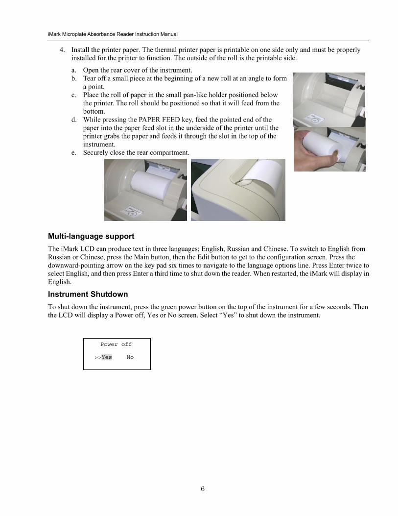
iMark Microplate Absorbance Reader Instruction Manual
7
Software Overview Capabilities The iMark Microplate Reader has on-board software that allows the user to set the plate reading and data analysis conditions to save these settings as a test protocol to read a microplate under this protocol and to print reports from the built-in printer The software communicates through the 4-line 20-character LCD and is controlled through the instruments membrane keypad
The software has three different protocol types End-point analysis Kinetic analysis and Checkmark validation The Checkmark validation function is used only by the administrator to verify quality control
The display shows the current mode The user can choose between these protocol types or can press the Memory Recall key to use the current protocol type
Quick Guide to Reading a Plate 1 Turn on the instrument Allow about 30 seconds for self-diagnosis The instrument needs to warm up for
about three minutes prior to reading a plate
2 Upon power up the login screen will appear Enter the login password (initial password 00000) press Enter
3 Program a protocol for your assay See page 22 for information on Editing a Kinetic protocol or page 25 for Editing an End Point Protocol Make sure filters installed correlate with information entered in reader firmware
4 Select the protocol of choice if programmed See the Memory Recall section on page 21 for detailed operation
5 Review or print parameters set in the protocol See the Editing End Point Protocol section on page 25 for details
6 Verify settings on Cutoff Report Limit STDs Mode Mapping and kit name parameters are as desired
7 Protocol setting can be printed see the Printing Reports and Protocols section on page 20 for information
8 All reports other than the raw data report require plate mapping Set the plate map with instructions from the Plate Map Setting Procedure section on page 33
9 The Matrix and Limit reports require assignment of upper and lower limits Set the upper and lower limits in the Editing End Point Protocol Limit setting window
10 The Cutoff report requires definition of the cutoff setting Refer to the Cutoff Setting Procedure section on page 26
11 The Curve fit and Concentration reports require that standard concentration and locations must be defined Refer to page 29 for details on how to define the standards and the curve fit parameters
12 Set the general reading mode (single or dual wavelength reading plate shaking read mode) following the instructions in the Mode Setting Procedure section on page 32
After warm-up is complete
13 Press the ldquoMainrdquo key The main screen appears on the LCD
14 Carefully place the microplate in the reading chamber Press the ldquoStartStoprdquo key to read
iMark Microplate Absorbance Reader Instruction Manual
8
Instrument Functions Calculations The Microplate Reader uses Beers Law to calculate the absorbance value of each well Beers Law states that absorbance is equal to the log10 of the ratio of the baseline measurement intensity (Io) to the sample measurement intensity (I)
Beers Law Absorbance = Log10 (IoI)
Before measuring the plate the reader takes a reading for all eight photodiode channels These values are recorded as the baseline measurement (Io) values for each channel respectively The reader then records the sample measurement (I) value for each well and calculates the absorbance using these values Channel-to-channel error is significantly reduced because the Io value for a given channel is used only in determining the absorbance of the wells of that channel
Security password The iMark Microplate Reader requires a user login with password This security feature helps to prevent any unwarranted modifications to the analysis conditionsprotocols and data stored in the instrument and identifies the operator on reports The reader has two user settings the Administrator and the Common user Each user level has its own security password
Memory Back-Up The battery back-up provides memory even after the reader is turned off
The following information will be saved in the memory until new reading parameters are set by the user or a new plate is read by the instrument Note that if a run is aborted before it is finished all the previous plate reading data remain in memory and none of the data from the aborted reading is stored
bull The ten latest sets of End-point protocol plate reading results
bull The two latest sets of Kinetic plate reading results (max 30 series of readings for each Kinetic Protocol)
bull 64 End-point Protocol settings and 2 Kinetic Protocol settings
bull A set of Checkmark reference data and the one latest set of Checkmark reading result
bull A set of standard curve data for the storage of standard curves and graphs
bull Eight wavelength values for filters
bull Laboratory name
bull Two security passwords (for the Administrator and the Common user)
bull Instrument serial number
In addition to the battery back-up memory the instrument has a small amount of non-volatile memory to keep the system information after the battery is dead The serial number is stored in this memory The average battery life is 5 years
iMark Microplate Absorbance Reader Instruction Manual
9
The first time the instrument is turned on or after a battery failure the following default information is held in the memory
1 Both Administrator and Common user security passwords are set to 00000
2 Laboratory name is Bio-Rad Laboratories
3 All wavelength values of the filters are set to --- nm
4 The date and time of the calendar chip are set to 1 day 1 month 00 year 0 hour and 0 minute
5 No plate reading data is available
6 End-point protocol is chosen and the protocol number is set to 1
7 No standard curve data for the storage of standard curves and graphs is available
Limits The Microplate Reader displays absorbance readings with absolute values as 3500 Out-of-range absorbance values (those with absolute values greater than 3500) are displayed as either or - For example if the absorbance is 4500 then the display will read and if the absorbance is -4500 the display will read -
iMark Microplate Absorbance Reader Instruction Manual
10
Report Types Two types of reports can be generated End-point protocol and Kinetic protocol Each of these and their subtypes are described below After these descriptions there are flow diagrams that show how to access specific choices
End-point Protocol Reports Nine types of End-Point Protocol reports can be generated raw data absorbance limit matrix cutoff curve fit concentration difference and TeSeE screening reports
1 Raw data report The Raw data report is the uncorrected absorbance values (without blank subtraction) In single-wavelength mode the reported value is the measured absorbance In dual-wavelength mode the reported value is the difference between the uncorrected readings taken with the measurement filter and with the reference filter
2 Absorbance report The Absorbance report is the blank-corrected absorbance values The mean absorbance value of all of the wells designated as assay blanks is calculated and then subtracted from all 96 values of the raw data set to produce the Absorbance report
Abs = Raw ndash Blank mean
Blank mean = Xn
SD = [X^2 ndash n(Blank mean)^2n-1]^12
Where
SD = Standard deviation
X = Sum total of the raw absorbance for each blank
X^2 = Sum total of the squared raw absorbance for each blank
n = Number of blanks
3 Limit report The Limit report provides a qualitative YESNO report Wells with blank-subtracted absorbance values between the upper and lower limits are represented with an asterisk () wells with absorbance values below the lower limit by minus signs (-) and wells with absorbance values greater than the upper limit by positive signs (+)
4 Matrix report The Matrix report provides a qualitative report of the relative magnitude of the absorbance values on the plate The absorbance range defined by the upper and lower limits is divided into 10 equal partitions numbered 0 through 9 The blank-subtracted absorbance value of each well is classified according to the partition of the matrix to which it corresponds and is reported as a signal digit Wells with absorbance values greater than the upper limit are reported by plus signs (+) and wells with absorbance values less than the lower limit by minus signs (-)
iMark Microplate Absorbance Reader Instruction Manual
11
5 Cutoff report The Cutoff report provides a qualitative report of the relative magnitude of the absorbance values or converted concentrations on the plate
Four types of cutoff reports are supported ranged constant single constant formula and ratio These and their subtypes are listed below
a Ranged Constant The user inputs Positive and Negative values to be used as the cutoff
For units designated Abs if the absorbance of a well is within the positive and negative cutoff values the well is scored If the absorbance of a well is greater than the positive value the well is scored + and if the absorbance of a well is below the negative value the well is scored -
For units not designated Abs the absorbance value of each well is converted to the concentration value using the curve fit constants of the curve fit report If the concentration of a well is within the positive and negative cutoff values the well is scored If the concentration of a well is greater than the positive value the well is scored + and if the concentration of a well is below the negative value the well is scored -
b Single Constant The user inputs Positive and Gray zone values to be used as the cutoff
For units designated Abs if the absorbance of a well is within the gray zone value of the positive cutoff value the well is scored If the absorbance of a well is more than the gray zone value and greater than the positive value the well is scored + and if the absorbance of a well is more than the gray zone value below the positive value the well is scored -
Upper cutoff absorbance = Positive absorbance + ((Gray zone100) Positive absorbance)
Lower cutoff absorbance = Positive absorbance ndash ((Gray zone100) Positive absorbance)
For units not designated Abs the absorbance value of each well is converted to the concentration value using the curve fit constants of the curve fit report If the concentration of a well is within the gray zone value of the positive cutoff value the well is scored If the concentration of a well is more than the gray zone value greater than the positive value the well is scored + and if the concentration of a well is more than the gray zone value below the positive value the well is scored -
Upper cutoff conc = Conc of positive controls + ((Gray zone100) Conc of positive controls)
Lower cutoff conc = Conc of positive controls - ((Gray zone100) Conc of positive controls)
c Formula The mean absorbance values of the Positive and Negative wells defined in the plate map are used for the cutoff formula calculation
The 12 types of formula-based cutoff reports are
i k CNx vii k + CNx
ii k CPx viii k + CPx
iii k COx ix k + COx
iv CNx k x kCNx + CPx
v CPx k xi xi (CNx + CPx) k
vi COx k xii k1CNx + k2CPx
iMark Microplate Absorbance Reader Instruction Manual
12
The result absorbance value of the formula calculation and the gray zone value that is entered by the user are used for the cutoff
The upper and lower cutoff values are
Upper cutoff absorbance = Result of a Formula + ((Gray zone100) Result of a Formula)
Lower cutoff absorbance = Result of a Formula - ((Gray zone100) Result of a Formula)
The absorbance range of the upper and lower cutoff is divided into 10 equal partitions numbered 0 through 9 The absorbance value of each well is classified according to the partition of the matrix to which it corresponds and is reported as a signal digit Wells with absorbance values greater than the upper cutoff are reported by plus signs (+) and wells with absorbance values less than the lower cutoff by minus signs (-)
d Ratio The mean absorbance value of the Calibrator wells defined in the plate map and the concentration value entered by the user are used for the cutoff ratio Before the cutoff the absorbance value of each well is converted into the concentration value The ratio of ConcentrationAbsorbance of Calibrator is applied to the conversion Then the cutoff is done with the defined Positive and Negative or the defined Positive and Gray zone values
6 Curve Fit Report The Curve fit report provides a regression analysis based on the absorbance values of a series of standards There are ten types of curve fits supported with the onboard software on iMark Microplate readers
i 5P Logistic Rodbard ii 4P Logistic Rodbard iii 5P Logistic Cook-Wilkenson iv 4P Logistic Cook-Wilkenson v 5P Exponential vi Sigmoid Logistic vii Linear regression viii Quadratic regression ix Cubic x Point-To-Point regression
The onboard software calculates the best fit of the defined curve between each set of two consecutive data points in the standard curve of absorbance vs concentration And then it generates the report with the coefficients of regression the correlation coefficient and the standard error
For readers with the optional internal printer or with an external ESCP printer which accepts ESCP code a graph of the standard curve may be generated when selected in the report parameter
7 Concentration Report In case of the curve fit the Concentration report also provides the regression analysis After the calculation of the curve fit it calculates the concentrations values of the samples and generates the report
In case of the cutoff constant with the unit not designated Abs and in case of the cutoff ratio the reader generates the list of concentration of each well
8 Difference Report The Difference report is the subtraction report between the neighboring columns or row
iMark Microplate Absorbance Reader Instruction Manual
13
9 TeSeE Screening Report Analysis of the TeSeE screening assay results can be done with two pre-programmed protocols ldquoTeSeErdquo protocol is stored in Endpoint Protocol position 5 and ldquoTeSeE eqrdquo is stored in Endpoint Protocol position 6 as factory default setting Both protocols are locked
TeSeE screening report is generated only if these protocols are selected as current active protocol Plate is first validated according to negative and positive controls validation criteria samples are then compared to the calculated cut-off
Criteria for plate validation are set as follows
Criteria 1 Individual Negative Control must be lt 0150
Number of valid Negative Control must be gt= 3
Criteria 2 Individual Negative Control must be lt 1400 Negative Control average
Number of valid Negative Control must be gt= 2
Criteria 3 Positive Control average must be gt= 1000
Cutoff is calculated as follows
TeSeE
Positive cutoff = Negative Control average + 0210
Negative cutoff = (Negative Control average + 0210) 0900
TeSeE eq
Positive cutoff = Negative Control average + 0210
Negative cutoff = Negative Control average + 0090
Samples are interpreted as follows
ldquoPOSrdquo Positive when sample OD gt= Positive cutoff
ldquoNEGrdquo Negative when sample OD lt Negative cutoff
ldquordquo Gray zone NEG cutoff =lt sample OD lt POS cutoff
iMark Microplate Absorbance Reader Instruction Manual
14
Protocol
Security
Filters
Date Set
Lab name
Cutoff
Report
Limit
STDs
Mode
Mapping
Kit name
Not Used
Constant
Control
Formula
Ratio
Ranged Cutoff Single Cutoff
Ranged Cutoff Single Cutoff
12 choices of cutoff formula
Concentration
Unit
Cutoff value
Cutoff Values setting Gray zone setting when single cutoff
Cutoff Control setting Gray zone setting when single cutoff
Coefficient setting of selected formula
0 - 9999
17 choices of unit
Cutoff Values setting Gray zone setting when single Cutoff
Ranged Cutoff Single Cutoff
Raw(Raw data) Abs(Absorbance) Lim(Limit) Mtx(Matrix) Cut(Cutoff) Crv(Curve fit) Cnc(Concentration) Dif(Difference)
Upper Limit Lower Limit For Limit Report
Standard information
Curvefit
Number of STD Concentration
Unit
Curvefit type Graph axis
Set Photo mode Set Shaking
Set Read mode
Manual mapping
Automatic mapping
Change password
Change user
End-point Analysis Protocol
Up to 12 Standards 0 to 9999 17 choices
12 choices of curve fit type 4 choices of graph axis combination of Log and Linear
SingleDual Wavelength Shake (Yes No) Speed (High Low Mid) Time Read Speed (FastStep) and Read Mode (NormalEval)
Func key to switch [N] to [F] [N] for sample number [F] for sample
Func key to switch from [ABC] to [abc] to [sym] key to move cursor
For current user mode Administrator or common user Administrator has power to switch
Filter wavelength setting for 1-8 positions ldquo0rdquo for no filter
DayMonthYear HourMin
Func key to switch from [ABC] to [abc] to [sym] key to move cursor
Save STDC
Language
Save STD Curve
Rename STD Curve
Select Language
5 choices of storage number
5 choices of STD curve
Func key to switch from [ABC] to [abc] to [sym] key to move cursor
Choices of pre-installed language for LCD and report printout
BlankCNCWCPCOQCCalibratorSampleReplicate well
Recall Setting Select STD Curv
Recall YesNo Selection 5 choices of memorized STD curve
Edit
Bold for menu pages
LCD adj and key to change contrast
Italic for program pages
iMark Microplate Absorbance Reader Instruction Manual
15
Kinetic Protocol Reports Four types of Kinetic protocol reports can be generated absorbance kinetic plots linear regression and GALT reports
1 Absorbance Report The Kinetic Absorbance report is the series of absorbance data in the kinetic sequence
2 Kinetic Plots Report The Kinetic plots are the absorbance plots of each well in the plate It is available for readers with the optional internal printer or with an external ESCP printer which accepts ESCP code
3 Linear Regression Report The Linear Regression report provides the calculation of Kinetic reaction rate for each well using the linear regression
4 GALT Report The GALT report calculates the following formula for each well between two readings of a plate
GALT = (R2 ndash R1) k
Where R1 = Absorbance value of 1st reading
R2 = Absorbance value of 2nd reading
k = GALT factor
iMark Microplate Absorbance Reader Instruction Manual
16
Func key to switch from [ABC] to [abc] to [sym] key to move cursor
Func key to switch from [ABC] to [abc] to [sym] key to move cursor
Func key to switch from [ABC] to [abc] to [sym] key to move cursor
DayMonthYear HourMin
Filter wavelength setting for 1-8 positions ldquo0rdquo for no filter
Edit
Kinetic Analysis Protocol
Protocol
Security
Filters
Date Set
Lab Name
Change password
Change user
LockUnlock
Mode
Report
Calc
Mapping
Assay
Kit name
Reading Inter
Shaking Phmode
Speed
Number of reads (2-30) start delay time (0-999) Reading interval time Shake (FirstEverydisable) Speed (High Low Mid) Time Single Dual wavelength Read Speed (FastStep)
CC Limit (correlation coefficient limit) Calcrange (calculation range of reading number) for Linear regression Report
GALT factor k input (0- 9999) Result = (2nd read ndash 1st read)k for GALT Report
Manual mapping
Automatic mapping
Func key to switch [N] to [F] [N] for sample number [F] for sample type
General Kinetic or GALT assay assay type selection
Absorbance KINETIC Plots Linear regression when General Kinetic Assay selected GALT report when GALT Kinetic assay selected
For current user mode Administrator or Common user Administrator has power to switch
Special Buttons
Memory Recall
Main
Protocol Plate Data
Report Protocol
End point Kinetic
Checkmark
1-64 End point protocol storage 1-2 Kinetic protocol storage Checkmark reader test
Printout
Returns to MAIN screen
SaveSTDC
Language
BlankCNCWCPCOQCCalibratorSampleReplicate well
Save STD Curve
Rename STD Curve
Select Language
5 choices of storage number
5 choices of STD curve
Choices of pre-installed language for LCD and report printout
Bold for menu pages
LCD adj and key to change contrast
Italic for program pages
iMark Microplate Absorbance Reader Instruction Manual
17
Screen by Screen Procedures Initial Startup
01Kinetic-1 M405(1)R605(6)30read Shake999sMidEvery 382402 180901
End point mode
Kinetic mode
Self-diagnosis iMark Microplate Reader 1305 180901
System Login User Administrator Password Press ENTER
Login SCREEN
01EndPoint Assay01 M405(1)R655(6) Shake999sMid 382402 180901
Checkmark Validation Program
180901
Checkmark mode
Initializing reader
MAIN SCREEN
Self-Diagnosis This screen will appear upon power-up and during self-diagnosis Date and time are also indicated on this screen
Initialization After self-diagnosis the system initializes all the hardware
Security Check The system requires a password to confirm that the user is the authorized operator Pressing the ChangeRight arrow key will switch the user mode between Common user and Administrator Password for both Common user and Administrator is set as ldquo00000rdquo upon factory shipment Operator can change the password in the EDIT menu See Security
System Ready When this MAIN screen is on the LCD the StartStop key can be pressed for microplate reading Pressing StartStop key will begin reading with the current protocol There are three kinds of MAIN screens depending on the current protocol type Endpoint Kinetic and Checkmark program The four arrow keys Numeral keys Main key and Enter key are inactive StartStop Memory Recall Edit Print and Paper Feed keys are active
01EndPoint Assay01 M405(1)R655(6) Shake999sMid
180901
Kit name for current active protocol
01Kinetic-1 M405(1)R605(6)30read Shake999sMidEvery 382402 180901
Kinetic M Measurement wavelength and its position in the filter disk R Reference wavelength and its position in the filter disk Number of reading for KINETIC
Storage number in memory of current active protocol
Plate shaking parameters period in seconds and speed
M Measurement wavelength and its position in the filter disk R Reference wavelength and its position in the filter disk
Date (day month year)
Plate shaking parameters Period in seconds Speed (fast middle slow) Mode (before every read before first read and no shake)
End point
iMark Microplate Absorbance Reader Instruction Manual
18
Configuring the System NOTE To return to the previous screen use the backleft arrow key
Edit Menu
Security function raquoChange Password bullChange user bullLockUnlock Prtl
Change Password
LockUnlock
Change user
Change Password Current New Common user
Security for current active Protocol [Lock] Unlock
System Login User Administrator Password Press ENTER
Change Password Select ldquoChange Passwordrdquo in the Security Menu Enter the current password then move the cursor to the 3rd line and enter a new password Press Enter to complete the field entry The system will return to the previous Security Menu Change User Mode Select ldquoChange userrdquo in the Security Menu Select a desired user mode by pressing the Right Arrow key Enter the appropriate Password for the selected user mode Press Enter to complete the field entry The system will return to the previous Security Menu LockUnlock Protocol Select ldquoLockUnlock Prtlrdquo in the Security Menu Move the selected mark ldquo[ ]rdquo to the desired position Lock or Unlock using the Right Arrow key Press Enter to complete the field entry The system will return to the previous Security Menu If ldquoLockrdquo is selected the current active protocol will be protected against modification made by a Common user If ldquoUnlockrdquo is selected the current active protocol can be modified by any user mode NOTE Only the Administrator has authority to lock and unlock the Checkmark Protocol
Edit Menu This menu can be accessed by pressing the Edit key in the MAIN SCREEN
Security Menu Security Setting Select ldquoSecurityrdquo in the Edit Menu screen and press Enter The Security Menu appears on the screen
raquoProtocol Labname Security SaveSTDC Filters Language Date set LCD adj
iMark Microplate Absorbance Reader Instruction Manual
19
1400nm 5650nm 2450nm 6nm 3475nm 7nm 4650nm 8nm
Filter
DayMonthYear 16 05 01 Hour Minutes 18 55
Date set
Enter Lab name Bio Rad Laboratories uarr [ABC]
Lab name
Filter Setting Move the cursor to the desired position by using the Up Down and Right arrow keys Enter the filter wavelength on the selected position using the number keys If the selected position of the filter disk is empty enter three ldquordquo Press Enter to complete the field entry The system will return to the previous Edit Menu screen
Calendar Setting Move the cursor to the desirable position for date or time input by using the Up Down and Right arrow keys Enter the present date or time using the number keys Press Enter to complete the field entry The system will return to the previous Edit Menu screen
Lab Name Setting Use the Up and Down arrow keys to select from ldquoArdquo to ldquoZrdquo and symbols Use the Number keys for numeric input Use the Right arrow key to move the cursor to the right Use the Left arrow key to return the cursor to the Edit Menu screen Pressing the FUNCrdquo key will toggle the character mode between Upper case alphabet Lower case alphabet and symbol The current character mode is indicated on the lower right corner of the LCD
Save STD Curve gt Save STD Curve Rename STD Curve
Save STDC Save STDC Setting Select ldquoSave STDCrdquo in Edit Menu screen above and press Enter The Save STD Curve Menu appears on the screen Move the cursor to the desired position by using the Up and Down arrow keys
Select STD storage gt 1120304 1500 2 3150304 1030
Select for renaming gt 1160304 1125 2 3150304 1030
Save STD Curve To save a STD Curve select the storage number between 1 and 5 Use the Up and Down arrow keys to move the cursor to the desired storage number and press Enter to complete the selection After the storage number selection the rdquoAre you surerdquo message appears Select ldquoYesrdquo or ldquoNordquo and press Enter In case of ldquoYesrdquo the reader saves the STD Curve and returns to the Edit Menu screen If the curve fit calculation is not done or has not finished successfully an error message will appear and the STD Curve will not be saved STD curve does not
exist yet Press any key
Save STD Curve 1160304 1125 Are you sure gt Yes No
Rename STD Curve To change a name of an STD Curve select a storage number between 1 and 5 Use the Up and Down arrow keys to move the cursor to the desired storage number and press Enter to complete the selection Use the Up and Down arrow keys to select from ldquoArdquo to ldquoZrdquo and symbol Use the Number keys for numeric input Use the Right arrow key to move the cursor to the right Use the Left arrow key to return the cursor to the Edit Menu screen Pressing the FUNCrdquo key will toggle the character mode between Upper case alphabet Lower case alphabet and symbol The current character mode is indicated on the lower right corner of the LCD
1160304 1125 gtSTD Curve 1 lt
[ABC]
Save STD Curve
Rename STD Curve
iMark Microplate Absorbance Reader Instruction Manual
20
Printing Reports and Protocol information
Print menu raquoReports bullProtocol
Print Menu Print Menu Access this menu screen by pressing the Print key in the MAIN screen Printing Reports Select ldquoReportsrdquo and press Enter to print the current active plate data report Printing Protocol Information Select ldquoProtocolrdquo and press Enter to print all parameter settings in the current active protocol Stop Printing Press the StartStop key during printing to stop the print job immediately When printing is completed the system automatically returns to the MAIN screen
Select Language raquoEnglish bull bull bull
Language Changing Language Select a desired language using the Up and Down arrow keys and press Enter to complete the selection The system will generate a message for an immediate power off to restart Select ldquoYesrdquo and press Enter to activate the selected new language The newly-changed language will be applied to the LCD screen and printed reports Power off
gtgtYes No
LCD Contrast 12345678901234567890
laquo 26 raquo ENTER to complete
Adjusting LCD Contrast Adjust LCD contrast by using the Right and Left arrow keys and press Enter to complete the adjustment
LCD adj
iMark Microplate Absorbance Reader Instruction Manual
21
Memory Recall Operation
01 200500 1400 02raquo210500 1700 03 200500 1800 darr04raquo200500 1900
01raquo200500 0900 02raquo200500 1000
Memory Recall raquoProtocol bullPlate Data
Protocol type menu
Data type menu
End Point
Kinetic
End Point
Kinetic
Memory Recall Menu
Select protocol type raquoEnd Point
bullKinetic bullCheckmark
Select Protocol 02 uarrraquo Protocol -2 Protocol -3 darr Protocol -4
Select Protocol 01 raquo Kinetic -1 GALT
Select data type raquoEnd Point
bullKinetic bullCheckmark
200501 0900
Checkmark
Checkmark program has been activated Press any key
Checkmark
Selecting Protocol Move the cursor to the position of the desired protocol and press Enter to complete the selection NOTE ldquordquo indicates the currently activated protocol and ldquordquo indicates a security locked protocol There is no protocol selection with ldquoCheckmarkrdquo When a protocol is selected the system will then automatically return to the MAIN screen
Changing Current Active Protocol Select ldquoProtocolrdquo in Memory Recall menu above and press Enter The Select Protocol type menu will appear on the screen Select a protocol using the Up and Down arrow keys Press Enter to complete the selection
Selecting Plate Data Move the cursor to the position of the desired plate data and press Enter to complete the selection NOTE ldquordquo indicates the currently activated plate data There is only one storage for ldquoCheckmarkrdquo data When plate data is selected the system automatically returns to the MAIN screen
Changing Current Active Plate Data Select ldquoPlate Datardquo using the Memory Recall button and press Enter The Data type menu will appear Use the Up and Down arrow keys to select a plate data type Press Enter to complete the selection
This menu screen can be accessed by pressing the Memory Recall key in the MAIN screen
iMark Microplate Absorbance Reader Instruction Manual
22
Editing the Kinetic Protocol
Select ldquoProtocolrdquo in the Edit Menu and press Enter The Kinetic Protocol menu will appear on the screen if the current active protocol type is Kinetic
Reading speed [Fast mode] Step mode
Speed
raquoReading Speed Inter Shaking Phmode
Kinetic Mode
Kinetic Protocol Menu
raquoMode Report Calc Kit name Mapping Assay
This menu screen can be accessed by selecting ldquoModerdquo in the Kinetic Protocol menu above
Number of Reading = 20 (2-30) Start Delay time = 25 sec(0-999)
Reading
Number of Reading = 2 Start Delay time = 25 sec(0-999)
Number of Readings and Start Delay Time Setting Press the Up or Down arrow key to change the number Enter the appropriate numbers with the numeral keys and press Enter to complete the field entry The system will return to the Kinetic Edit Menu If GALT is the current assay type the number of reading fields is fixed at 2 Press the StartStop key to set the Start Delay time enter a value and press Enter until the reading starts
1-gt2raquo 100 sec 2-gt3 100 sec 3-gt4 100 sec darr4-gt5 100 sec
Inter Use same interval between all reads
raquoYes No
Setting Reading Intervals The system prompts the operator to set a reading interval before each plate run Move the cursor to the desired selection ldquoYesrdquo or ldquoNordquo and press Enter The system generates the interval entry screen Move to the active entry field by pressing the Up and Down arrow keys and enter appropriate numbers using numeral keys Press Enter to complete all field entries The system will return to the Kinetic Mode menu
Photometric Dual Measurement405 nm Reference 655 nm
Ph mode Photometric Mode Setting When the ldquoPhotometricrdquo field is activated pressing the Right arrow key will switch the field entry ldquoSinglerdquo lt-gtrdquoDualrdquo Pressing the Up or Down arrow keys will move the cursor to the next entry field Pressing the Right arrow key when the wavelength field is activated will change the wavelength to the next available selection installed in the reader Press Enter to complete all field entries
Shaking parameters Before Every read Speed Mid Time 999 sec
Shaking Plate Shake Parameters When the ldquoBeforerdquo field is activated pressing the Right arrow key will change the field entry ldquoEveryrdquo-gtrdquo--rdquo-gtrdquoFirstrdquo-gt When the ldquoSpeedrdquo field is activated pressing the Right arrow key will change the field entry ldquoMidrdquo -gtrdquoHirdquo-gtrdquoLowrdquo-gt When the ldquoTimerdquo field is activated enter the time value for plate shaking period using the numeral keys Press Enter to complete all field entries
Selecting Reading Speed Use the Up or Down arrow keys to switch the selection Press Enter to complete the selection
Edit Menu raquoProtocol Labname Security bullSaveSTDC Filters bullPrinter Date set
This menu screen can be accessed by pressing the Edit key in the MAIN screen
iMark Microplate Absorbance Reader Instruction Manual
23
Kit name for 01 raquoGAP TEST IgGlaquo uarr [ABC]
Kit name
Calculation
Mapping
Assay
Assay type selection raquo[General KINETIC] GALT assay
Calculation Param CC Limit 0910
Calcrange 10 - 20
Select Mapping mode raquoManual mapping bullAutomatic mapping
raquo[Linregression] bullAbsorbance bullKINETIC Plots
Report
Plate Mapping See Plate Map setting procedure
Result = (R2 ndash R1)k k = 999999 R11st Reading R22nd Reading
If GALT
Setting the Kit Name Use the Up and Down arrow keys to select alphabet from ldquoArdquo to ldquoZrdquo and space Use the Number keys for numeric input Use the Right arrow key to move the cursor to the right Use the Left arrow key to return to the Protocol Menu screen Pressing ldquoFUNCrdquo key will change the character mode Upper case alphabet -gt Lower case alphabet -gt symbol The current character mode is indicated on the lower right corner of the LCD
Kinetic Protocol Menu
Selecting Kinetic Assay Type Move the cursor to the desired Assay type by pressing the Up or Down arrow keys Press Enter to complete the selection The item with mark ldquo[ ]rdquo is the currently selected item GALT assay Result = factor x (2nd Read ndash 1st Read)
Selecting Report Type Move the cursor to the desired report type by pressing the Up or Down arrow keys Pressing the Right arrow key will select or deselect the item Press Enter to complete the selection Note When GALT assay is selected ldquoGALT reportrdquo shall be the only one option on this screen
raquoMode bullReport bullCalc bullKit name bullMapping bullAssay
Calculation Parameter Setting When the ldquoCC Limitrdquo field is activated pressing the numeral key will enter the desired numbers Press Enter to complete all field entries If the GALT Reports is activated pressing the numeral keys will enter the desired numbers Press Enter to complete all field entries
iMark Microplate Absorbance Reader Instruction Manual
24
Checkmark Value Setting (Administrator only)
raquoSerial Report bullLinearity ref bullMaxCV bullFilter Check ref
Checkmark Protocol Menu
raquoSerial 0000 Reptype Simple
405nm S10158 Linearity S20309 reference S31401 S42109
MaxCV raquoS115 Linearity S205 reference S302 S402
Filter max min 4051875 0329 4501167 0954 darr 4920596 0103
Serial Report
Linearity reference
Max CV
Filter check reference
Filter max min uarr 5401875 0329 6201167 0954 6900596 0103
Setting the Serial Number and Report Type Pressing the Up and Down arrow keys will move the cursor and change the field entry When ldquoSerial rdquo field is active enter the serial number that will be shown in the data sheet of the Checkmark plate using the numeral keys When the ldquoRep typerdquo field is active pressing the Right arrow key will switch the report type between ldquoSimplerdquo and ldquoFullrdquo
Setting the Linearity Reference Value Pressing the Up or Down arrow keys will move the field entry from S1 to S4 Pressing the Right arrow key will change the wavelength 405 nm-gt450 nm-gt492 nm-gt540 nm-gt620 nm-gt690 nm Use the numeral keys for the reference value setting Pressing Enter will complete all field entries at all wavelength
Max CV setting Pressing the Up or Down arrow keys will move the field entry from S1 to S4 Use the numeral keys for the Max CV setting Press Enter to complete all field entries
Setting the Filter Check Reference Value Initial screen shows the reference entries for 405 nm to 492 nm and pressing the Down arrow key at the bottom of the screen entries will scroll to the next page for 540 nm to 690 nm Pressing the Up Down and Right arrow keys will move the field entry Use the numeral keys for the filter check reference value setting Press Enter to complete all field entries
Select ldquoProtocolrdquo in the Edit Menu and press Enter The Checkmark Protocol Menu will appear on the screen if the current active protocol type is Checkmark mode
Edit Menu raquoProtocol bullLabname bullSecurity bullSaveSTDC bullFilters bullPrinter bullDate set
This menu screen can be accessed by pressing the Edit key in the MAIN screen
iMark Microplate Absorbance Reader Instruction Manual
25
Editing End Point Protocol
Upper Limit= 2000 Lower Limit= 0000 input range 0ndash3500 Upper gt Lower
Standard menu raquoSTD information
bullCurvefit bullRecall STD Curve
raquoCutoff bullMode bullReport bullMapping bullLimit bullKit name bullSTDs
Cutoff
See Plate Map setting procedure
See Standard setting procedure
See Mode setting procedure
raquo[Not use] bullRatio bullConstant bullContrl bullFormula
raquoSet photo mode bullSet shaking bullSet read mode
Select mapping mode raquoManual mapping bullAutomatic mapping
Mapping
Mode
Report
STDs
Limit
Kit name for 01 raquoGAP TEST IgGlaquo uarr [ABC]
Kit name See Kit name setting in Editing Kinetic Protocol
See Cutoff setting procedure
Select ldquoProtocolrdquo in Edit Menu screen above and press Enter The End point Protocol Menu will appear on the screen if the current active protocol type is End point mode
End Point Protocol Menu
raquo[Raw] bullMtx bullCnc bullAbs bullCut bullDif bullLim bullCrv
If ldquoDifrdquo selected
[Raw] bullMtx bullCncbullAbs bullCut [Dif] bullLim bullCrv raquorow odd-even
Seting the Report Type Use the Up and Down Arrow key to move the cursor and press the Right Arrow key to select or deselect the report type Selected report type is marked as ldquo[ ]rdquo Press Enter to complete the selection
Setting the Limit Value Use the Up and Down Arrow key to move the cursor and enter the OD value using the numeral keys The OD value range is 0000 - 3500 Press Enter to complete the selection
Edit Menu raquoProtocol bullLabname bullSecurity bullSaveSTDC bullFilters bullPrinter bullDate set
This menu screen can be accessed by pressing the Edit key in the MAIN screen
iMark Microplate Absorbance Reader Instruction Manual
26
Cutoff Setting Procedure
Cutoff Setting Menu This menu is entered by choosing Cutoff in the End Point Protocol Menu It is used to set the cutoff type The cutoff type marked with ldquo[ ]rdquo is the current selection The Up and Down arrow keys move the cursor to the desired item in the menu list When the desired parameters have been selected press Enter twice to accept the selection and to continue to the next screen Not use means that the reader does not generate the cutoff report Four types of cutoff are supported
1 Cutoff Constant 2 Cutoff Control 3 Cutoff Formula 4 Cutoff Ratio
a Cutoff Constant
Selection of SingleRanged Cutoff Constant This menu selects Single or Ranged cutoff type The cutoff type marked with ldquo[ ]rdquo is the current selection The Enter key seals the selection and resumes to the next setting screen
Single Cutoff Constant The Numerical keys and the Decimal point key are used to enter the positive and gray zone values The Right arrow key is used to select the unit The Up and Down arrow keys move the cursor to the desired parameter of the single cutoff The Enter key sets all values and selection of the cutoff constant and returns the user to the previous screen Ranged Cutoff Constant The Numerical keys and the Decimal point key are used to enter the positive and negative values The Right arrow key is used to select the unit The Up and Down arrow key moves the cursor to the desired ranged cutoff parameters The Enter key sets all values and selection of the cutoff constant and returns to the previous screen NOTE Two available Cutoff constants are ldquoAbsorbancerdquo and ldquoConcentrationrdquo If Abs is chosen the Absorbance cutoff will be done with the cutoff constant parameters defined and the absorbance report is generated For other units defined in the curve fit setting the Concentration value using the curve fit and then cutoff is done with the cutoff constant parameters defined and the concentration value of each well It is necessary to set the curve fit parameters
raquoNot usex bullRatio [Const] bullContrl bullFormula
raquoPositive gt= 9999 Gray zone 50 Unit moll
raquoPositive gt= 9999 Negative lt 1999 NegativeltPositive Unit moll
raquoRanged cutoff [Single cutoff]
Single cutoff
Ranged
iMark Microplate Absorbance Reader Instruction Manual
27
b Cutoff Control
Selection of SingleRanged Cutoff Control This menu screen selects Single or Ranged cutoff type The cutoff type marked with ldquo[ ]rdquo is the current selection The Enter key seals the selection and resumes to the next setting screen
Single Cutoff Control The Numerical keys are used to enter the gray zone value The unit is fixed to Abs The Enter key sets the value of the cutoff control and returns to the previous screen Ranged Cutoff Control There is no parameter to set for the ranged cutoff control The Enter key returns to the previous screen NOTE CNx is the mean absorbance value of Negative control wells and CPx is the mean absorbance value of Positive control wells These wells are defined in the plate map setting The cutoff is done with the Positive and Negative value to the absorbance value of each well
c Cutoff Formula
Selection of Formula This menu screen selects a formula for cutoff calculation The formula marked with ldquo[ ]rdquo is the current selection The Up and Down arrow keys move the cursor to the desired formula type The movement of the cursor follows the scroll of this screen The Enter key marks the selection and advances the user to the next setting screen The supported formula types are
1 k CNx 2 k CPx 3 k COx 4 CNx k 5 CPx k 6 COx k 7 k + CNx 8 k + CPx 9 k + COx 10 kCNx + CPx 11 ( CNx + CPx ) k 12 k1CNx + k2CPx
Coefficient for Cutoff Formula 1 to 11 The Numerical keys and the Decimal point key are used to enter the coefficient k and gray zone values The Up and Down arrow key moves the cursor to the desired parameter of the cutoff formula The Enter key sets all values of the cutoff formula and returns to the previous screen
Positive gt= CNx Gray zone 50 Unit Abs
Positive gt= CPx Negative lt CNx Unit Abs
Enter key to accept
raquoRanged cutoff [Single cutoff]
Single cutoff
Ranged
Input coefficient k = 001 (001-10) Gray zone 50(0-99)
k CNx k CPx k COx CNx k CPx k COx k k + CNx k + CPx k + COx k CNx + CPx (CNx + CPx) k
uarr raquoCNx k bullCPx k bullCOx k darr bullk + CNx
Select formula raquo[kCNx ] bullkCPx darr bullkCOx
uarr raquok + CPx bullk + COx bullkCNx + CPx darr bull(CNx + CPx) k
uarr raquok1CNx + k2CPx
Page-1
Page-2
Page-3
Page-4
iMark Microplate Absorbance Reader Instruction Manual
28
Coefficient for Cutoff Formula 12 The Numerical keys and the Decimal point key are used to enter the coefficient k1 and k2 and gray zone values The Up and Down arrow key moves the cursor to the desired cutoff formula The Enter key sets the all values of the cutoff formula and returns to the previous screen NOTE CNx is the mean absorbance value of Negative control wells CPx is the mean absorbance value of Positive control wells and COx is the mean absorbance value of Cutoff control wells These wells are defined on the plate map setting The cutoff value is calculated using the defined formula with the defined values and coefficients
d Cutoff Ratio
Ratio to Calibrator In this screen there are three items for setting the ratio to calibrator The Up and Down arrow key moves the cursor to the desired item in the menu list The Enter key seals the selection and resumes to the next setting screen
Concentration of Calibrator The Numerical keys and the Decimal point key are used to enter the calibrator concentration value The Enter key sets the value and returns to the previous screen Unit of Calibrator Seventeen standard units are supported The unit marked with ldquo[ ]rdquo is the current selection The setting procedure is the same as the unit selection of Standards Cutoff Value Setting This menu screen selects Single or Ranged cutoff type The cutoff type marked with ldquo[ ]rdquo is the current selection The Enter key marks the selection and continues to the next setting screen Single Cutoff Control The Numerical keys are used to enter the Positive cutoff concentration value and gray zone value The Enter key sets these cutoff ratio values and returns to the previous screen Ranged Cutoff Control The Numerical keys are used to input the Positive and the Negative cutoff concentration values The Enter key sets these cutoff ratios and returns to the previous screen NOTE The calibrator concentration value is used to convert the absorbance value of each well into a concentration value The ratio of ConcentrationAbsorbance of Calibrator well is applied to the conversion The cutoff uses defined Positive and Negative values to the converted concentration value of each well
Input coefficient k1 = 001 (001-10) k2 = 100 (001-10) Gray zone 50(0-99)
k1 CNx + k2 CPx
Ratio to Calibrator raquoConcentration bullUnit bullCutoff value
Concentration 9999 unit moll
uarrraquo 01 ugdl 02 ngml 03[ pgml] darr 04 pmml
raquoPositive gt= 9999 Gray zone 50
Unit moll
raquoPositive gt= 9999 Negative lt 9999 NegativeltPositive
Unit moll
raquoRanged cutoff [Single cutoff]
Concentration
Unit
Cutoff value
Single cutoff
Ranged cutoff
iMark Microplate Absorbance Reader Instruction Manual
29
Standard Setting Procedure
Standard Curve Setting Menu This menu screen is entered by choosing STDs in the End Point Protocol Menu screen It is used to set the concentration data and the curve fit type for a standard curve or to recall a memorized standard curve The Up and Down arrow key moves the cursor to the desired item in the menu list The Enter key seals the selection and continues to the next setting screen
a STD Information Setting
STD Information In this screen there are three items for setting the concentration data of standards The Up and Down arrow keys move the cursor to the desired item in the menu list The Enter key seals the selection and continues to the next setting screen
Number of Standards The Numerical keys are used to enter the number of standards ldquo0rdquo means that the curve fit report is not used The Enter key sets the number and returns to the previous screen The maximum number of standards is 12 Concentration The Numerical keys and the Decimal point key are used to enter the concentration values of standards The Up and Down arrow keys move the cursor to the desired position The movement of the cursor also follows the scroll of this screen The Enter key sets all values of the concentration of standards and returns to the previous screen Unit Seventeen units are supported The unit marked with ldquo[ ]rdquo is the current selection The Up and Down arrow keys move the cursor to the desired unit type The movement of the cursor also follows the scroll of this screen Press Enter twice to select the unit type and to return to the previous screen The supported types of unit are
1 moll 11 pgml 2 m moll 12 Uml 3 u moll 13 IUml 4 n moll 14 uIUml 5 p moll 15 mIUml 6 mgl 16 EU 7 ngl 17 Arbit 8 pgl 9 ugdl 10 ngml
STD information raquoNumber of STD bullConcentration bullUnit
STD 1 0512 STD 2 1012 STD 3 1512 darr STD 4 2053
Standard menu raquoSTD information bullCurve fit bullRecall STD curve
Concentration
Number of STD
Number of STD = 05 (0 2ndash12)
uarrraquo 01 ugdl 02 ngml 03[ pgml] darr 04 pmml
Unit
iMark Microplate Absorbance Reader Instruction Manual
30
b Curve Fit Setting
Curve Fit In this screen there are two choices to set the curve fit The Up and Down arrow keys move the cursor to the desired item in the menu list The Enter key seals the selection and resumes to the next setting screen
Curve Fit Type 10 types of curve fit are supported as below The curve fit type marked with ldquo[ ]rdquo is the current selection The Up and Down arrow key moves the cursor to the desired curve fit type The movement of the cursor follows the scroll of this screen Press Enter twice to select the unit type and to return to the previous screen The supported curve fit types are
1 5P Logistic Rodbard 2 4P Logistic Rodbard 3 5P Logistic Cook-Wilkenson 4 4P Logistic Cook-Wilkenson 5 5P Exponential 6 Sigmoid Logistic 7 Linear regression 8 Quadratic regression 9 Cubic 10 Point To Point regression
Graph Axis Four types of graph are supported The curve fit type marked with ldquo[ ]rdquo is the current selection The Up and Down arrow keys move the cursor to the desired graph type Press Enter twice to select the unit type and to return to the previous screen The supported graph types are
1 Log - Log 2 Log - Linear 3 Linear - Log 4 Linear - Linear
uarr 5p logisticRodb raquo 4p logisticRodb [5p logisticCook] darr 4p logisticCook
raquo X-Log Y-Log [X-Log Y-Lin] X-Lin Y-Log X-Lin Y-Lin
Curve fit type
Graph axis
Curve fit setting raquoCurve fit type bullGraph axis
iMark Microplate Absorbance Reader Instruction Manual
31
c Recall STD Curve Setting
Recall Setting of Standard Curve In this screen there are two items for setting the Recall STD curve as below The Up and Down arrow keys move the cursor to the desired item in the menu list
1 Recall setting (YesNo) 2 Selecting the storage number of standard curves (1 -gt 5)
Recall Setting Move the cursor to the desired position using the Up Down or Right arrow keys Enter key accepts the setting and returns the user to the standard menu screen
Yes Recalling of the standard curve is active No Recalling of the standard curve is inactive
Storage Number Selection Five memories are selectable The vacant memory (marked with asterisks on the date and time field) is also selectable It is necessary to save a standard curve before using its protocol Move the cursor to the desired position using the Up and Down keys This setting screen consists of two parts The Right arrow key is used to switch the indication field between the date and time to the standard curve name Move the cursor to the desired position using the Up and Down keys The Enter key accepts the storage number and returns to the standard menu screen NOTE If the recall of standard curve is active (the recall setting is ldquoYesrdquo) the standard information setting and the curve fit setting will be invalidated and their setting screens will not open
Recall STD curve raquoRecall setting bullSelect STD curve
Recall setting raquoYes No
Recall setting
Select STD Curve raquo1160304 1125
2 darr 3150304 1030
Select STD Curve uarrraquo4
5
Select STD Curve raquo1 STD Curve 1
2 STD Curve 2 darr 3 STD Curve 3
Select STD Curve uarrraquo4 STD Curve 4
5 STD Curve 5
Select STD curve
Right arrow key
iMark Microplate Absorbance Reader Instruction Manual
32
Mode Setting Procedure
Mode Setting Menu This menu screen is entered by choosing the Mode in the End Point Protocol Menu screen or the Kinetic Protocol Menu screen It is used to set the plate reading conditions The Up and Down arrow keys move the cursor to the desired item in the menu list The Enter key seals the selection and resumes to the next setting screen
a Set Photo Mode
Photo Mode In this screen the user chooses Single or Dual wavelength measurement and assigns the measurement and reference (for dual wavelength measurement) filters The assignment of the reference filter appears for dual wavelength measurement The Up and Down arrow keys move the cursor to the desired parameter The Right arrow key chooses SingleDual wavelength measurement and selects the installed filter on the Filters of Edit Menu screen The Enter key seals the selection and returns to the previous screen
b Set Shaking
Shaking In this screen the user selectsdeselects shaking function sets the shaking strength and enters the shaking time A shaking time of 0s indicates no shaking The maximum shaking time is 999 seconds The Up and Down arrow key moves the cursor to the desired parameters The Right arrow key toggles between YesNo (SelectDeselect) shaking or selects strength LowMiddleHigh The Numerical keys are used to enter the shaking time The Enter key seals the selection and returns the user to the previous screen
c Set Read Mode
Read Mode In this screen the user chooses Fast or Step reading and also chooses Normal or Evaluation mode The ldquo[ ]rdquoindicates the current selection The Up and Down arrow key moves the cursor to the desired parameters The Right arrow key chooses FastStep speed or chooses NormalEval mode The Enter key seals the selection and returns to the previous screen The followings are the description of each read mode parameter Reading speed
Fast reading 6 secsingle wavelength reading 10 secdual wavelength reading
Step reading 15 secsingle wavelength reading 30 secdual wavelength reading
Reading mode
Normal mode Plate reading once Evaluation mode Four plate readings per one of measurement are performed and
the average data of their plate readings is generated as a plate data
Photometric Dual Measurement400 nm Reference 655 nm
Set Shake parameters ShakeYes SpeedMid Time 199sec(0-999)
raquoReading speed [Fast ] Step bullRead mode [Normal] Eval
raquoSet Photo mode bullSet shaking bullSet read mode
Photometric Single Measurement400 nm
iMark Microplate Absorbance Reader Instruction Manual
33
Plate Map Setting Procedure
Select Mapping Mode Menu This menu screen is entered by choosing Mapping in the End Point Protocol Menu screen or the Kinetic Protocol Menu screen It is used to map the plate format The Up and Down arrow keys move the cursor next to the desired item of menu list The Enter key seals the selection and changes this screen to the next setting screen
a Manual Mapping
Manual Mapping In this screen the user can set the plate format manually Ten well types can be set Well types The supported well types are
Well type Indication on LCD
1 Blank B 2 Sample X00hellipX99 3 Standard S01hellipS99 4 In-kit Control Positive Control CP0hellipCP9 5 Weak Positive Control CW0hellipCW9 6 Negative Control CN0hellipCN9 7 Cutoff Control CO0hellipCO9 8 Calibrator CL0hellipCL9 9 QC Control QC0hellipQC9 10 Empty well -
The key assignments of well type are ldquo0EMPrdquo Empty well ldquo5QCrdquo Quality Control well ldquo1SMPrdquo Sample well ldquo6CALrdquo Calibrator well ldquo2BLKrdquo Blank well ldquo7CPrdquo Positive Control well ldquo3STDrdquo Standard well ldquo8CNrdquo Negative Control well ldquo4COrdquo Cutoff Control well ldquo9CWrdquo Weak Positive Control well
Two Edit Modes in Plate Mapping There are two editing modes for well type input mode and for well number input The current input mode is displayed at the upper left corner of the screen When using the well type input mode the mode sign is ldquo[F]rdquo When using the well number input mode the mode sign is ldquoNrdquo The cursor that encloses the editing position of well has two types of enclosures depending on the mode For example ldquo[S01]rdquo accepts the well type keys that be assigned to the numerical keys and ldquoS01rdquo accepts the numerical input The mode is easily changed with the Decimal point key Key Functions The Up Down Right and Left arrow keys move the cursor to the desired well The movement of the cursor follows the scroll of this screen The Left arrow key will return the screen to the preceding screen or the select Mapping mode Menu only if the cursor is on column 1 At this time the selection screen appears (see the left figure) The Decimal point key changes the input mode The Numerical keys have two functions one to input the number and another to select a well type The Enter key checks the consistency between the edited plate map and other parameters memorizes the plate map into the protocol and changes this screen back to the preceding screen If it finds any inconsistency a warning message will appear on the screen
Select Mapping mode raquoManual mapping bullAutomatic mapping
N 1 2 3 4 A B CN1 S01 S01 B B CN1 S02 S02 C B CN2 S03 S03 [F] 5 6 7 8 A X11 X12 X13 X14 B X21 X22 X23 X24 C X31 X32 X33[X34]
Discard change 1Yes 2No Press 1 or 2 key
iMark Microplate Absorbance Reader Instruction Manual
34
Acceptable Number Ranges for each well type 1 Blank and Empty wells do not use numbers 2 Sample and Standard wells 00 - 99 3 Standard wells 01 - 99 4 Control and Calibrator wells 0 - 9
b Automatic Mapping
Automatic Mapping The user can input the number of each well type in this screen These defined numbers are used to set a plate map automatically Well type Nine well types are available
1 BLK Blank (0-gt10) 2 CN Control CN (0-gt9) 3 CW Control CW (0-gt9) 4 CP Control CP (0-gt9) 5 CO Control CO (0-gt9) 6 QC Control QC (0-gt9) 7 CAL Calibrator (0-gt9) 8 SMP Sample (0-gt96) 9 REP Replicate well (1-gt4)
It is possible to define the number of blanks samples calibrators and controls But the number of Standards is not included because standards are defined at the Standard Setting Menu The number of replicate wells is also included It is used for replicating each well type individually Key Functions The Up Down Right and Left arrow keys are used to move the cursor to the next position The Numerical keys are used to input the mapping parameters The Enter key accepts the mapping parameters and sets a plate map automatically using these parameters During the execution of the plate mapping the Plate auto-mapping completed message appears on the screen After that the user returns automatically to the previous Protocol Menu screen If the Left arrow key is pressed at the left end position of the cursor the left figure will appear on the screen If the user chooses Yes the system will return to the previous Protocol Menu screen If the user chooses No the system will stay in this setting screen Assigning Order and Direction of plate mapping Assigning Order The order of blanks standards samples calibrators and controls are fixed as follows Numbering for standards samples calibrators and controls is started at 1
1 Blank 2 Standard 1 -gt12 ---- NOTE 3 Control CN 1-gt9 4 Control CW 1-gt9 5 Control CP 1-gt9 6 Control CO 1-gt9 7 Control QC 1-gt9 8 Calibrator 1-gt9 9 Sample 1-gt96 10 Empty well NOTE If ldquoCutoff Controlrdquo ldquoValue by Formulardquo or ldquoRatio to Calibratorrdquo is
selected for the Cutoff plate mapping skips arranging the standards Assigning Direction The placing direction of the mapping is limited to the column direction as below
Column direction A1 -gt H1 A2 -gt H2 ----- A12 -gt H12
Discard change 1Yes 2No Press 1 or 2 key
Automatic mapping BLK= 1 CP = 1 CAL= 0 CN = 1 CO = 0 SMP=93 CW = 0 QC = 0 REP= 1
Plate auto-mapping completed
iMark Microplate Absorbance Reader Instruction Manual
35
Warning and Error of Automatic Mapping Warning screen If the total number of wells mapped exceeds 96 wells a warning message in the left figure appears on the screen The calculation of the total number of mapping wells is as follows
(Blanks+Standards+CNs+CWs+CPs+COs+QCs+Calibrators+Sample)Replicates The plate mapping is executed normally and the exceeded part is invalidated Error screen If one or more mapping parameters are over the input range an error message in the left figure will appear on the screen On the third line of the LCD the name of the parameter which is out of range and its input range will appear
Example ldquoBLK 0 ndash 10rdquo In case there is more than one error the first parameter of errors is indicated By pressing any key the user returns to the automatic mapping screen Example of automatic mapping An example of automatic mapping is as below 1 Conditions of each parameter
Blank = 1 Standard = 8 Control CN = 2 CW = 0 CP = 2 CO = 0 QC = 0 Calibrator = 1 Sample = 32 Replicate number = 2
2 Plate mapping data
1 2 3 4 5 6 7 8 9 10 11 12 A B C D E F G H
B B S1 S1 S2 S2 S3 S3
S4 S4 S5 S5 S6 S6 S7 S7
S8 S8 CN1 CN1 CN2 CN2 CP1 CP1
CP2 CP2 CL1 CL1 X1 X1 X2 X2
X3 X3 X4 X4 X5 X5 X6 X6
X7 X7 X8 X8 X9 X9 X10 X10
X11 X11 X12 X12 X13 X13 X14 X14
X15 X15 X16 X16 X17 X17 X18 X18
X19 X19 X20 X20 X21 X21 X22 X22
X23 X23 X24 X24 X25 X25 X26 X26
X27 X27 X28 X28 X29 X29 X30 X30
X31 X31 X32 X32 E E E E
Warning The total Of mapped wells has Exceeded 96 Press any key
Entered value is Out of range BLK 0 ndash 10 Press any key
iMark Microplate Absorbance Reader Instruction Manual
36
Instrument Maintenance
Caution Electrical shock hazard Always disconnect the instrument from the AC power source before opening the service compartment
Caution The lamp and the lamp cover may be very hot Use caution and allow the lamp to cool
before attempting service
Installing Interference Filters 1 With the power off open the rear cover of the instrument by pressing the
release latch located on the top left portion of the cover 2 Locate the filter wheel on the left side of the instrument Note that the
filter wheel has eight filter positions 3 Rotate the filter wheel to the desired filter Grasp the top of filter frame
and pull up to remove the filter 4 Insert the new filter into the desired filter position 5 Ensure that the new filter is added to the filter list as follows Main
menu-gtEdit-gtFilters
Changing the Lamp 1 With the power off open the rear cover of the instrument by pressing the
release latch located on the top left portion of the cover 2 Remove the two screws on the black plastic cover and carefully remove
the plastic cover 3 Remove the screw on the metal cover Lift the cover up and away from
the instrument This will allow the lamp to be pulled free from the lamp housing
4 Holding the ceramic base in one hand and the lamp housing in the other carefully pull the lamp free of the base
5 Carefully insert the new lamp firmly in the ceramic base Apply even pressure when inserting the lamp so that the bulb dose not become misaligned in the reflector housing Be extremely careful not to touch the front glass of the lamp during installation
6 Position the new lamp into the housing so that the plastic guides hold the flange of the lamp
7 Carefully place the metal cover over the lamp Tighten the screw 8 Replace the plastic cover and tighten the screws 9 Close the rear cover
iMark Microplate Absorbance Reader Instruction Manual
37
Troubleshooting and Error Messages
The iMark Microplate Reader constantly monitors several functions and displays appropriate messages on the LCD as errors are encountered
Error Recommendation
LCD appears blank on power up
a Power is not turned on The AC outlet is non-functional
b Unit is not plugged into AC outlet or power code is not attached to the instrument
Check power cord connections at outlet and on the rear panel of the instrument
1
c The AC outlet is non-functional Check circuit breakers or fuses
Instrument displays ldquoLight bulb errorrdquo message indicating that the bulb is burned out
Check whether lamp is emitting light
a Lamp is not emitting light Replace the lamp as described in x
2
b Lamp is emitting light Check the alignment of the lamp in the housing Align or replace the lamp if necessary
Printer will not print on command
3
a Printer paper is not installed properly Verify that the paper is properly installed Refer to x for details
Plate carriage jams during reading and ldquoPlate carrier errorrdquo is displayed
a Plate is not seated in carriage properly Press the STOP button immediately Position the plate carefully in the carriage making certain that it is properly seated
4
b Plate height is exceeding 16mm Use Microplate which is less than 16mm in height
5 LCD displays ldquoFilter missingrdquo Install a filter in the empty position Select the installed filter by pressing Edit key
6 LCD displays ldquoFilter disk jammedrdquo indicating that the filter wheel is not turning freely
Turn off the instrument and inspect the filter wheel Turn by hand to verify that the wheel is moving freely Make sure all the filters are properly installed and firmly seated Contact your Bio-Rad representative if the filter wheel is jammed or if the problem persists
7 LCD displays ldquoFilter not installedrdquo Enter the Edit Menu by pressing Edit key and set up the filters
iMark Microplate Absorbance Reader Instruction Manual
38
Wells have color but absorbance values seem low
a Incorrect filter used for measurement andor reference wavelength
Check wavelength used in analysis Read plate in single wavelength mode at all wavelength to verify that the proper filter was used The measurement wavelength should produce the highest absorbance
b The best measurement wavelength filter for the substrate in use has not been installed in the filter wheel
Check references for the substrate you are using or determine the best measurement wavelength by analyzing the substrate product on a scanning spectrophotometer Custom filters are available from 400 to 750 nm
8
c The filters have been switched in the wheel Check that the filters are installed in the correct position
9 ldquoPrinter errorrdquo displayed Check for paper jam Install the printer paper correctly
10 ldquoBattery errorrdquo displayed The internal battery is almost dead Contact your local Bio-Rad office
11 The following messages are displayed ldquoMemory errorrdquo ldquoCalendar errorrdquo ldquoLCD hardware errorrdquo ldquoPrinter errorrdquo ldquoLight level errorrdquo ldquoDA conversion errorrdquo ldquoAD conversion errorrdquo ldquoEEPROM errorrdquo ldquoUSB errorrdquo
Contact your local Bio-Rad office if these problems persist
iMark Microplate Absorbance Reader Instruction Manual
39
Instrument Specifications Computer interface USB 20
Plate shaking 3 speeds (low mid high) Programmable time period 0 - 999 seconds
Data storage The most recent 10 data plates for end-point most recent 2 data plates of 30 readings for kinetic readings protocol data and calendarclock function shall be kept in memory by a lithium battery even when the power is off Average lifetime of the battery shall be 5 years
Warm-up time 3 minutes
Photometric Methods Single and dual wavelength
Photo detectors 8 silicon photodiodes for measurement and 1 silicon photodiode for reference
Light source Tungsten halogen lamp 20W with 3000 hours average lifetime
Spectral range 400 nm to 750 nm
Interference filters Wavelength tolerance plusmn30 nm Band width 10 nm typically
Filter capacity 8 filters
Reading speed Fast Reading 6 sec with single wavelength reading 10 sec with dual wavelength reading
Step Reading 15 sec with single wavelength reading 25 sec with dual wavelength reading
These times are minimum interval times between repetitive reads using onboard KINETIC protocol
Indication range 0000 to 35 OD
Resolution 0001 OD
Accuracy plusmn10 or 0010 from 0 to 30 OD at 490 nm
Linearity plusmn10 from 0 to 20 OD plusmn20 from 0 to 30 OD
Reproducibility 10 or 0005 OD from 0 to 20 OD 15 from 20 to 30 OD
Inter-channel variability 15 or 0005 OD from 0 to 30 OD
Stability and Drift 0010 OD at OD=1 with single wavelength reading
Built-in Printer Thermal printer Paper width 80mm
Line Voltage Universal input 100 - 240 VAC 5060Hz
Power consumption (max) 100 VA max
Dimensions (W x D x H 346 mm x 377 mm x 164 m mm
Weight 55 kg
Operating Environment 15ordmC - 40ordmC up to 90 relative humidity without condensation
Storage Temperature 10ordmC - 50ordmC up to 90 relative humidity without condensation
Life ScienceGroup
07-0816 0108 Sig 120710013301i Rev A USEG
Bio-RadLaboratories Inc
Web site wwwbio-radcom USA 800 4BIORAD Australia 61 02 9914 2800 Austria 01 877 89 01 Belgium 09 385 55 11 Brazil 55 21 3237 9400 Canada 905 364 3435 China 86 21 6426 0808 Czech Republic 420 241 430 532 Denmark 44 52 10 00 Finland 09 804 22 00 France 01 47 95 69 65Germany 089 318 84 0 Greece 30 210 777 4396 Hong Kong 852 2789 3300 Hungary 36 1 455 8800 India 91 124 4029300 Israel 03 963 6050 Italy 39 02 216091 Japan 03 6361 7000 Korea 82 2 3473 4460 Mexico 52 555 488 7670 The Netherlands 0318 540666 New Zealand 0508 805 500 Norway 23 38 41 30 Poland 48 22 331 99 99 Portugal 351 21 472 7700 Russia 7 495 721 14 04 Singapore 65 6415 3188 South Africa 27 861 246 723 Spain 34 91 590 5200 Sweden 08 555 12700 Switzerland 061 717 95 55 Taiwan 886 2 2578 7189 United Kingdom 020 8328 2000
iMark Microplate Absorbance Reader Instruction Manual
8
Instrument Functions Calculations The Microplate Reader uses Beers Law to calculate the absorbance value of each well Beers Law states that absorbance is equal to the log10 of the ratio of the baseline measurement intensity (Io) to the sample measurement intensity (I)
Beers Law Absorbance = Log10 (IoI)
Before measuring the plate the reader takes a reading for all eight photodiode channels These values are recorded as the baseline measurement (Io) values for each channel respectively The reader then records the sample measurement (I) value for each well and calculates the absorbance using these values Channel-to-channel error is significantly reduced because the Io value for a given channel is used only in determining the absorbance of the wells of that channel
Security password The iMark Microplate Reader requires a user login with password This security feature helps to prevent any unwarranted modifications to the analysis conditionsprotocols and data stored in the instrument and identifies the operator on reports The reader has two user settings the Administrator and the Common user Each user level has its own security password
Memory Back-Up The battery back-up provides memory even after the reader is turned off
The following information will be saved in the memory until new reading parameters are set by the user or a new plate is read by the instrument Note that if a run is aborted before it is finished all the previous plate reading data remain in memory and none of the data from the aborted reading is stored
bull The ten latest sets of End-point protocol plate reading results
bull The two latest sets of Kinetic plate reading results (max 30 series of readings for each Kinetic Protocol)
bull 64 End-point Protocol settings and 2 Kinetic Protocol settings
bull A set of Checkmark reference data and the one latest set of Checkmark reading result
bull A set of standard curve data for the storage of standard curves and graphs
bull Eight wavelength values for filters
bull Laboratory name
bull Two security passwords (for the Administrator and the Common user)
bull Instrument serial number
In addition to the battery back-up memory the instrument has a small amount of non-volatile memory to keep the system information after the battery is dead The serial number is stored in this memory The average battery life is 5 years
iMark Microplate Absorbance Reader Instruction Manual
9
The first time the instrument is turned on or after a battery failure the following default information is held in the memory
1 Both Administrator and Common user security passwords are set to 00000
2 Laboratory name is Bio-Rad Laboratories
3 All wavelength values of the filters are set to --- nm
4 The date and time of the calendar chip are set to 1 day 1 month 00 year 0 hour and 0 minute
5 No plate reading data is available
6 End-point protocol is chosen and the protocol number is set to 1
7 No standard curve data for the storage of standard curves and graphs is available
Limits The Microplate Reader displays absorbance readings with absolute values as 3500 Out-of-range absorbance values (those with absolute values greater than 3500) are displayed as either or - For example if the absorbance is 4500 then the display will read and if the absorbance is -4500 the display will read -
iMark Microplate Absorbance Reader Instruction Manual
10
Report Types Two types of reports can be generated End-point protocol and Kinetic protocol Each of these and their subtypes are described below After these descriptions there are flow diagrams that show how to access specific choices
End-point Protocol Reports Nine types of End-Point Protocol reports can be generated raw data absorbance limit matrix cutoff curve fit concentration difference and TeSeE screening reports
1 Raw data report The Raw data report is the uncorrected absorbance values (without blank subtraction) In single-wavelength mode the reported value is the measured absorbance In dual-wavelength mode the reported value is the difference between the uncorrected readings taken with the measurement filter and with the reference filter
2 Absorbance report The Absorbance report is the blank-corrected absorbance values The mean absorbance value of all of the wells designated as assay blanks is calculated and then subtracted from all 96 values of the raw data set to produce the Absorbance report
Abs = Raw ndash Blank mean
Blank mean = Xn
SD = [X^2 ndash n(Blank mean)^2n-1]^12
Where
SD = Standard deviation
X = Sum total of the raw absorbance for each blank
X^2 = Sum total of the squared raw absorbance for each blank
n = Number of blanks
3 Limit report The Limit report provides a qualitative YESNO report Wells with blank-subtracted absorbance values between the upper and lower limits are represented with an asterisk () wells with absorbance values below the lower limit by minus signs (-) and wells with absorbance values greater than the upper limit by positive signs (+)
4 Matrix report The Matrix report provides a qualitative report of the relative magnitude of the absorbance values on the plate The absorbance range defined by the upper and lower limits is divided into 10 equal partitions numbered 0 through 9 The blank-subtracted absorbance value of each well is classified according to the partition of the matrix to which it corresponds and is reported as a signal digit Wells with absorbance values greater than the upper limit are reported by plus signs (+) and wells with absorbance values less than the lower limit by minus signs (-)
iMark Microplate Absorbance Reader Instruction Manual
11
5 Cutoff report The Cutoff report provides a qualitative report of the relative magnitude of the absorbance values or converted concentrations on the plate
Four types of cutoff reports are supported ranged constant single constant formula and ratio These and their subtypes are listed below
a Ranged Constant The user inputs Positive and Negative values to be used as the cutoff
For units designated Abs if the absorbance of a well is within the positive and negative cutoff values the well is scored If the absorbance of a well is greater than the positive value the well is scored + and if the absorbance of a well is below the negative value the well is scored -
For units not designated Abs the absorbance value of each well is converted to the concentration value using the curve fit constants of the curve fit report If the concentration of a well is within the positive and negative cutoff values the well is scored If the concentration of a well is greater than the positive value the well is scored + and if the concentration of a well is below the negative value the well is scored -
b Single Constant The user inputs Positive and Gray zone values to be used as the cutoff
For units designated Abs if the absorbance of a well is within the gray zone value of the positive cutoff value the well is scored If the absorbance of a well is more than the gray zone value and greater than the positive value the well is scored + and if the absorbance of a well is more than the gray zone value below the positive value the well is scored -
Upper cutoff absorbance = Positive absorbance + ((Gray zone100) Positive absorbance)
Lower cutoff absorbance = Positive absorbance ndash ((Gray zone100) Positive absorbance)
For units not designated Abs the absorbance value of each well is converted to the concentration value using the curve fit constants of the curve fit report If the concentration of a well is within the gray zone value of the positive cutoff value the well is scored If the concentration of a well is more than the gray zone value greater than the positive value the well is scored + and if the concentration of a well is more than the gray zone value below the positive value the well is scored -
Upper cutoff conc = Conc of positive controls + ((Gray zone100) Conc of positive controls)
Lower cutoff conc = Conc of positive controls - ((Gray zone100) Conc of positive controls)
c Formula The mean absorbance values of the Positive and Negative wells defined in the plate map are used for the cutoff formula calculation
The 12 types of formula-based cutoff reports are
i k CNx vii k + CNx
ii k CPx viii k + CPx
iii k COx ix k + COx
iv CNx k x kCNx + CPx
v CPx k xi xi (CNx + CPx) k
vi COx k xii k1CNx + k2CPx
iMark Microplate Absorbance Reader Instruction Manual
12
The result absorbance value of the formula calculation and the gray zone value that is entered by the user are used for the cutoff
The upper and lower cutoff values are
Upper cutoff absorbance = Result of a Formula + ((Gray zone100) Result of a Formula)
Lower cutoff absorbance = Result of a Formula - ((Gray zone100) Result of a Formula)
The absorbance range of the upper and lower cutoff is divided into 10 equal partitions numbered 0 through 9 The absorbance value of each well is classified according to the partition of the matrix to which it corresponds and is reported as a signal digit Wells with absorbance values greater than the upper cutoff are reported by plus signs (+) and wells with absorbance values less than the lower cutoff by minus signs (-)
d Ratio The mean absorbance value of the Calibrator wells defined in the plate map and the concentration value entered by the user are used for the cutoff ratio Before the cutoff the absorbance value of each well is converted into the concentration value The ratio of ConcentrationAbsorbance of Calibrator is applied to the conversion Then the cutoff is done with the defined Positive and Negative or the defined Positive and Gray zone values
6 Curve Fit Report The Curve fit report provides a regression analysis based on the absorbance values of a series of standards There are ten types of curve fits supported with the onboard software on iMark Microplate readers
i 5P Logistic Rodbard ii 4P Logistic Rodbard iii 5P Logistic Cook-Wilkenson iv 4P Logistic Cook-Wilkenson v 5P Exponential vi Sigmoid Logistic vii Linear regression viii Quadratic regression ix Cubic x Point-To-Point regression
The onboard software calculates the best fit of the defined curve between each set of two consecutive data points in the standard curve of absorbance vs concentration And then it generates the report with the coefficients of regression the correlation coefficient and the standard error
For readers with the optional internal printer or with an external ESCP printer which accepts ESCP code a graph of the standard curve may be generated when selected in the report parameter
7 Concentration Report In case of the curve fit the Concentration report also provides the regression analysis After the calculation of the curve fit it calculates the concentrations values of the samples and generates the report
In case of the cutoff constant with the unit not designated Abs and in case of the cutoff ratio the reader generates the list of concentration of each well
8 Difference Report The Difference report is the subtraction report between the neighboring columns or row
iMark Microplate Absorbance Reader Instruction Manual
13
9 TeSeE Screening Report Analysis of the TeSeE screening assay results can be done with two pre-programmed protocols ldquoTeSeErdquo protocol is stored in Endpoint Protocol position 5 and ldquoTeSeE eqrdquo is stored in Endpoint Protocol position 6 as factory default setting Both protocols are locked
TeSeE screening report is generated only if these protocols are selected as current active protocol Plate is first validated according to negative and positive controls validation criteria samples are then compared to the calculated cut-off
Criteria for plate validation are set as follows
Criteria 1 Individual Negative Control must be lt 0150
Number of valid Negative Control must be gt= 3
Criteria 2 Individual Negative Control must be lt 1400 Negative Control average
Number of valid Negative Control must be gt= 2
Criteria 3 Positive Control average must be gt= 1000
Cutoff is calculated as follows
TeSeE
Positive cutoff = Negative Control average + 0210
Negative cutoff = (Negative Control average + 0210) 0900
TeSeE eq
Positive cutoff = Negative Control average + 0210
Negative cutoff = Negative Control average + 0090
Samples are interpreted as follows
ldquoPOSrdquo Positive when sample OD gt= Positive cutoff
ldquoNEGrdquo Negative when sample OD lt Negative cutoff
ldquordquo Gray zone NEG cutoff =lt sample OD lt POS cutoff
iMark Microplate Absorbance Reader Instruction Manual
14
Protocol
Security
Filters
Date Set
Lab name
Cutoff
Report
Limit
STDs
Mode
Mapping
Kit name
Not Used
Constant
Control
Formula
Ratio
Ranged Cutoff Single Cutoff
Ranged Cutoff Single Cutoff
12 choices of cutoff formula
Concentration
Unit
Cutoff value
Cutoff Values setting Gray zone setting when single cutoff
Cutoff Control setting Gray zone setting when single cutoff
Coefficient setting of selected formula
0 - 9999
17 choices of unit
Cutoff Values setting Gray zone setting when single Cutoff
Ranged Cutoff Single Cutoff
Raw(Raw data) Abs(Absorbance) Lim(Limit) Mtx(Matrix) Cut(Cutoff) Crv(Curve fit) Cnc(Concentration) Dif(Difference)
Upper Limit Lower Limit For Limit Report
Standard information
Curvefit
Number of STD Concentration
Unit
Curvefit type Graph axis
Set Photo mode Set Shaking
Set Read mode
Manual mapping
Automatic mapping
Change password
Change user
End-point Analysis Protocol
Up to 12 Standards 0 to 9999 17 choices
12 choices of curve fit type 4 choices of graph axis combination of Log and Linear
SingleDual Wavelength Shake (Yes No) Speed (High Low Mid) Time Read Speed (FastStep) and Read Mode (NormalEval)
Func key to switch [N] to [F] [N] for sample number [F] for sample
Func key to switch from [ABC] to [abc] to [sym] key to move cursor
For current user mode Administrator or common user Administrator has power to switch
Filter wavelength setting for 1-8 positions ldquo0rdquo for no filter
DayMonthYear HourMin
Func key to switch from [ABC] to [abc] to [sym] key to move cursor
Save STDC
Language
Save STD Curve
Rename STD Curve
Select Language
5 choices of storage number
5 choices of STD curve
Func key to switch from [ABC] to [abc] to [sym] key to move cursor
Choices of pre-installed language for LCD and report printout
BlankCNCWCPCOQCCalibratorSampleReplicate well
Recall Setting Select STD Curv
Recall YesNo Selection 5 choices of memorized STD curve
Edit
Bold for menu pages
LCD adj and key to change contrast
Italic for program pages
iMark Microplate Absorbance Reader Instruction Manual
15
Kinetic Protocol Reports Four types of Kinetic protocol reports can be generated absorbance kinetic plots linear regression and GALT reports
1 Absorbance Report The Kinetic Absorbance report is the series of absorbance data in the kinetic sequence
2 Kinetic Plots Report The Kinetic plots are the absorbance plots of each well in the plate It is available for readers with the optional internal printer or with an external ESCP printer which accepts ESCP code
3 Linear Regression Report The Linear Regression report provides the calculation of Kinetic reaction rate for each well using the linear regression
4 GALT Report The GALT report calculates the following formula for each well between two readings of a plate
GALT = (R2 ndash R1) k
Where R1 = Absorbance value of 1st reading
R2 = Absorbance value of 2nd reading
k = GALT factor
iMark Microplate Absorbance Reader Instruction Manual
16
Func key to switch from [ABC] to [abc] to [sym] key to move cursor
Func key to switch from [ABC] to [abc] to [sym] key to move cursor
Func key to switch from [ABC] to [abc] to [sym] key to move cursor
DayMonthYear HourMin
Filter wavelength setting for 1-8 positions ldquo0rdquo for no filter
Edit
Kinetic Analysis Protocol
Protocol
Security
Filters
Date Set
Lab Name
Change password
Change user
LockUnlock
Mode
Report
Calc
Mapping
Assay
Kit name
Reading Inter
Shaking Phmode
Speed
Number of reads (2-30) start delay time (0-999) Reading interval time Shake (FirstEverydisable) Speed (High Low Mid) Time Single Dual wavelength Read Speed (FastStep)
CC Limit (correlation coefficient limit) Calcrange (calculation range of reading number) for Linear regression Report
GALT factor k input (0- 9999) Result = (2nd read ndash 1st read)k for GALT Report
Manual mapping
Automatic mapping
Func key to switch [N] to [F] [N] for sample number [F] for sample type
General Kinetic or GALT assay assay type selection
Absorbance KINETIC Plots Linear regression when General Kinetic Assay selected GALT report when GALT Kinetic assay selected
For current user mode Administrator or Common user Administrator has power to switch
Special Buttons
Memory Recall
Main
Protocol Plate Data
Report Protocol
End point Kinetic
Checkmark
1-64 End point protocol storage 1-2 Kinetic protocol storage Checkmark reader test
Printout
Returns to MAIN screen
SaveSTDC
Language
BlankCNCWCPCOQCCalibratorSampleReplicate well
Save STD Curve
Rename STD Curve
Select Language
5 choices of storage number
5 choices of STD curve
Choices of pre-installed language for LCD and report printout
Bold for menu pages
LCD adj and key to change contrast
Italic for program pages
iMark Microplate Absorbance Reader Instruction Manual
17
Screen by Screen Procedures Initial Startup
01Kinetic-1 M405(1)R605(6)30read Shake999sMidEvery 382402 180901
End point mode
Kinetic mode
Self-diagnosis iMark Microplate Reader 1305 180901
System Login User Administrator Password Press ENTER
Login SCREEN
01EndPoint Assay01 M405(1)R655(6) Shake999sMid 382402 180901
Checkmark Validation Program
180901
Checkmark mode
Initializing reader
MAIN SCREEN
Self-Diagnosis This screen will appear upon power-up and during self-diagnosis Date and time are also indicated on this screen
Initialization After self-diagnosis the system initializes all the hardware
Security Check The system requires a password to confirm that the user is the authorized operator Pressing the ChangeRight arrow key will switch the user mode between Common user and Administrator Password for both Common user and Administrator is set as ldquo00000rdquo upon factory shipment Operator can change the password in the EDIT menu See Security
System Ready When this MAIN screen is on the LCD the StartStop key can be pressed for microplate reading Pressing StartStop key will begin reading with the current protocol There are three kinds of MAIN screens depending on the current protocol type Endpoint Kinetic and Checkmark program The four arrow keys Numeral keys Main key and Enter key are inactive StartStop Memory Recall Edit Print and Paper Feed keys are active
01EndPoint Assay01 M405(1)R655(6) Shake999sMid
180901
Kit name for current active protocol
01Kinetic-1 M405(1)R605(6)30read Shake999sMidEvery 382402 180901
Kinetic M Measurement wavelength and its position in the filter disk R Reference wavelength and its position in the filter disk Number of reading for KINETIC
Storage number in memory of current active protocol
Plate shaking parameters period in seconds and speed
M Measurement wavelength and its position in the filter disk R Reference wavelength and its position in the filter disk
Date (day month year)
Plate shaking parameters Period in seconds Speed (fast middle slow) Mode (before every read before first read and no shake)
End point
iMark Microplate Absorbance Reader Instruction Manual
18
Configuring the System NOTE To return to the previous screen use the backleft arrow key
Edit Menu
Security function raquoChange Password bullChange user bullLockUnlock Prtl
Change Password
LockUnlock
Change user
Change Password Current New Common user
Security for current active Protocol [Lock] Unlock
System Login User Administrator Password Press ENTER
Change Password Select ldquoChange Passwordrdquo in the Security Menu Enter the current password then move the cursor to the 3rd line and enter a new password Press Enter to complete the field entry The system will return to the previous Security Menu Change User Mode Select ldquoChange userrdquo in the Security Menu Select a desired user mode by pressing the Right Arrow key Enter the appropriate Password for the selected user mode Press Enter to complete the field entry The system will return to the previous Security Menu LockUnlock Protocol Select ldquoLockUnlock Prtlrdquo in the Security Menu Move the selected mark ldquo[ ]rdquo to the desired position Lock or Unlock using the Right Arrow key Press Enter to complete the field entry The system will return to the previous Security Menu If ldquoLockrdquo is selected the current active protocol will be protected against modification made by a Common user If ldquoUnlockrdquo is selected the current active protocol can be modified by any user mode NOTE Only the Administrator has authority to lock and unlock the Checkmark Protocol
Edit Menu This menu can be accessed by pressing the Edit key in the MAIN SCREEN
Security Menu Security Setting Select ldquoSecurityrdquo in the Edit Menu screen and press Enter The Security Menu appears on the screen
raquoProtocol Labname Security SaveSTDC Filters Language Date set LCD adj
iMark Microplate Absorbance Reader Instruction Manual
19
1400nm 5650nm 2450nm 6nm 3475nm 7nm 4650nm 8nm
Filter
DayMonthYear 16 05 01 Hour Minutes 18 55
Date set
Enter Lab name Bio Rad Laboratories uarr [ABC]
Lab name
Filter Setting Move the cursor to the desired position by using the Up Down and Right arrow keys Enter the filter wavelength on the selected position using the number keys If the selected position of the filter disk is empty enter three ldquordquo Press Enter to complete the field entry The system will return to the previous Edit Menu screen
Calendar Setting Move the cursor to the desirable position for date or time input by using the Up Down and Right arrow keys Enter the present date or time using the number keys Press Enter to complete the field entry The system will return to the previous Edit Menu screen
Lab Name Setting Use the Up and Down arrow keys to select from ldquoArdquo to ldquoZrdquo and symbols Use the Number keys for numeric input Use the Right arrow key to move the cursor to the right Use the Left arrow key to return the cursor to the Edit Menu screen Pressing the FUNCrdquo key will toggle the character mode between Upper case alphabet Lower case alphabet and symbol The current character mode is indicated on the lower right corner of the LCD
Save STD Curve gt Save STD Curve Rename STD Curve
Save STDC Save STDC Setting Select ldquoSave STDCrdquo in Edit Menu screen above and press Enter The Save STD Curve Menu appears on the screen Move the cursor to the desired position by using the Up and Down arrow keys
Select STD storage gt 1120304 1500 2 3150304 1030
Select for renaming gt 1160304 1125 2 3150304 1030
Save STD Curve To save a STD Curve select the storage number between 1 and 5 Use the Up and Down arrow keys to move the cursor to the desired storage number and press Enter to complete the selection After the storage number selection the rdquoAre you surerdquo message appears Select ldquoYesrdquo or ldquoNordquo and press Enter In case of ldquoYesrdquo the reader saves the STD Curve and returns to the Edit Menu screen If the curve fit calculation is not done or has not finished successfully an error message will appear and the STD Curve will not be saved STD curve does not
exist yet Press any key
Save STD Curve 1160304 1125 Are you sure gt Yes No
Rename STD Curve To change a name of an STD Curve select a storage number between 1 and 5 Use the Up and Down arrow keys to move the cursor to the desired storage number and press Enter to complete the selection Use the Up and Down arrow keys to select from ldquoArdquo to ldquoZrdquo and symbol Use the Number keys for numeric input Use the Right arrow key to move the cursor to the right Use the Left arrow key to return the cursor to the Edit Menu screen Pressing the FUNCrdquo key will toggle the character mode between Upper case alphabet Lower case alphabet and symbol The current character mode is indicated on the lower right corner of the LCD
1160304 1125 gtSTD Curve 1 lt
[ABC]
Save STD Curve
Rename STD Curve
iMark Microplate Absorbance Reader Instruction Manual
20
Printing Reports and Protocol information
Print menu raquoReports bullProtocol
Print Menu Print Menu Access this menu screen by pressing the Print key in the MAIN screen Printing Reports Select ldquoReportsrdquo and press Enter to print the current active plate data report Printing Protocol Information Select ldquoProtocolrdquo and press Enter to print all parameter settings in the current active protocol Stop Printing Press the StartStop key during printing to stop the print job immediately When printing is completed the system automatically returns to the MAIN screen
Select Language raquoEnglish bull bull bull
Language Changing Language Select a desired language using the Up and Down arrow keys and press Enter to complete the selection The system will generate a message for an immediate power off to restart Select ldquoYesrdquo and press Enter to activate the selected new language The newly-changed language will be applied to the LCD screen and printed reports Power off
gtgtYes No
LCD Contrast 12345678901234567890
laquo 26 raquo ENTER to complete
Adjusting LCD Contrast Adjust LCD contrast by using the Right and Left arrow keys and press Enter to complete the adjustment
LCD adj
iMark Microplate Absorbance Reader Instruction Manual
21
Memory Recall Operation
01 200500 1400 02raquo210500 1700 03 200500 1800 darr04raquo200500 1900
01raquo200500 0900 02raquo200500 1000
Memory Recall raquoProtocol bullPlate Data
Protocol type menu
Data type menu
End Point
Kinetic
End Point
Kinetic
Memory Recall Menu
Select protocol type raquoEnd Point
bullKinetic bullCheckmark
Select Protocol 02 uarrraquo Protocol -2 Protocol -3 darr Protocol -4
Select Protocol 01 raquo Kinetic -1 GALT
Select data type raquoEnd Point
bullKinetic bullCheckmark
200501 0900
Checkmark
Checkmark program has been activated Press any key
Checkmark
Selecting Protocol Move the cursor to the position of the desired protocol and press Enter to complete the selection NOTE ldquordquo indicates the currently activated protocol and ldquordquo indicates a security locked protocol There is no protocol selection with ldquoCheckmarkrdquo When a protocol is selected the system will then automatically return to the MAIN screen
Changing Current Active Protocol Select ldquoProtocolrdquo in Memory Recall menu above and press Enter The Select Protocol type menu will appear on the screen Select a protocol using the Up and Down arrow keys Press Enter to complete the selection
Selecting Plate Data Move the cursor to the position of the desired plate data and press Enter to complete the selection NOTE ldquordquo indicates the currently activated plate data There is only one storage for ldquoCheckmarkrdquo data When plate data is selected the system automatically returns to the MAIN screen
Changing Current Active Plate Data Select ldquoPlate Datardquo using the Memory Recall button and press Enter The Data type menu will appear Use the Up and Down arrow keys to select a plate data type Press Enter to complete the selection
This menu screen can be accessed by pressing the Memory Recall key in the MAIN screen
iMark Microplate Absorbance Reader Instruction Manual
22
Editing the Kinetic Protocol
Select ldquoProtocolrdquo in the Edit Menu and press Enter The Kinetic Protocol menu will appear on the screen if the current active protocol type is Kinetic
Reading speed [Fast mode] Step mode
Speed
raquoReading Speed Inter Shaking Phmode
Kinetic Mode
Kinetic Protocol Menu
raquoMode Report Calc Kit name Mapping Assay
This menu screen can be accessed by selecting ldquoModerdquo in the Kinetic Protocol menu above
Number of Reading = 20 (2-30) Start Delay time = 25 sec(0-999)
Reading
Number of Reading = 2 Start Delay time = 25 sec(0-999)
Number of Readings and Start Delay Time Setting Press the Up or Down arrow key to change the number Enter the appropriate numbers with the numeral keys and press Enter to complete the field entry The system will return to the Kinetic Edit Menu If GALT is the current assay type the number of reading fields is fixed at 2 Press the StartStop key to set the Start Delay time enter a value and press Enter until the reading starts
1-gt2raquo 100 sec 2-gt3 100 sec 3-gt4 100 sec darr4-gt5 100 sec
Inter Use same interval between all reads
raquoYes No
Setting Reading Intervals The system prompts the operator to set a reading interval before each plate run Move the cursor to the desired selection ldquoYesrdquo or ldquoNordquo and press Enter The system generates the interval entry screen Move to the active entry field by pressing the Up and Down arrow keys and enter appropriate numbers using numeral keys Press Enter to complete all field entries The system will return to the Kinetic Mode menu
Photometric Dual Measurement405 nm Reference 655 nm
Ph mode Photometric Mode Setting When the ldquoPhotometricrdquo field is activated pressing the Right arrow key will switch the field entry ldquoSinglerdquo lt-gtrdquoDualrdquo Pressing the Up or Down arrow keys will move the cursor to the next entry field Pressing the Right arrow key when the wavelength field is activated will change the wavelength to the next available selection installed in the reader Press Enter to complete all field entries
Shaking parameters Before Every read Speed Mid Time 999 sec
Shaking Plate Shake Parameters When the ldquoBeforerdquo field is activated pressing the Right arrow key will change the field entry ldquoEveryrdquo-gtrdquo--rdquo-gtrdquoFirstrdquo-gt When the ldquoSpeedrdquo field is activated pressing the Right arrow key will change the field entry ldquoMidrdquo -gtrdquoHirdquo-gtrdquoLowrdquo-gt When the ldquoTimerdquo field is activated enter the time value for plate shaking period using the numeral keys Press Enter to complete all field entries
Selecting Reading Speed Use the Up or Down arrow keys to switch the selection Press Enter to complete the selection
Edit Menu raquoProtocol Labname Security bullSaveSTDC Filters bullPrinter Date set
This menu screen can be accessed by pressing the Edit key in the MAIN screen
iMark Microplate Absorbance Reader Instruction Manual
23
Kit name for 01 raquoGAP TEST IgGlaquo uarr [ABC]
Kit name
Calculation
Mapping
Assay
Assay type selection raquo[General KINETIC] GALT assay
Calculation Param CC Limit 0910
Calcrange 10 - 20
Select Mapping mode raquoManual mapping bullAutomatic mapping
raquo[Linregression] bullAbsorbance bullKINETIC Plots
Report
Plate Mapping See Plate Map setting procedure
Result = (R2 ndash R1)k k = 999999 R11st Reading R22nd Reading
If GALT
Setting the Kit Name Use the Up and Down arrow keys to select alphabet from ldquoArdquo to ldquoZrdquo and space Use the Number keys for numeric input Use the Right arrow key to move the cursor to the right Use the Left arrow key to return to the Protocol Menu screen Pressing ldquoFUNCrdquo key will change the character mode Upper case alphabet -gt Lower case alphabet -gt symbol The current character mode is indicated on the lower right corner of the LCD
Kinetic Protocol Menu
Selecting Kinetic Assay Type Move the cursor to the desired Assay type by pressing the Up or Down arrow keys Press Enter to complete the selection The item with mark ldquo[ ]rdquo is the currently selected item GALT assay Result = factor x (2nd Read ndash 1st Read)
Selecting Report Type Move the cursor to the desired report type by pressing the Up or Down arrow keys Pressing the Right arrow key will select or deselect the item Press Enter to complete the selection Note When GALT assay is selected ldquoGALT reportrdquo shall be the only one option on this screen
raquoMode bullReport bullCalc bullKit name bullMapping bullAssay
Calculation Parameter Setting When the ldquoCC Limitrdquo field is activated pressing the numeral key will enter the desired numbers Press Enter to complete all field entries If the GALT Reports is activated pressing the numeral keys will enter the desired numbers Press Enter to complete all field entries
iMark Microplate Absorbance Reader Instruction Manual
24
Checkmark Value Setting (Administrator only)
raquoSerial Report bullLinearity ref bullMaxCV bullFilter Check ref
Checkmark Protocol Menu
raquoSerial 0000 Reptype Simple
405nm S10158 Linearity S20309 reference S31401 S42109
MaxCV raquoS115 Linearity S205 reference S302 S402
Filter max min 4051875 0329 4501167 0954 darr 4920596 0103
Serial Report
Linearity reference
Max CV
Filter check reference
Filter max min uarr 5401875 0329 6201167 0954 6900596 0103
Setting the Serial Number and Report Type Pressing the Up and Down arrow keys will move the cursor and change the field entry When ldquoSerial rdquo field is active enter the serial number that will be shown in the data sheet of the Checkmark plate using the numeral keys When the ldquoRep typerdquo field is active pressing the Right arrow key will switch the report type between ldquoSimplerdquo and ldquoFullrdquo
Setting the Linearity Reference Value Pressing the Up or Down arrow keys will move the field entry from S1 to S4 Pressing the Right arrow key will change the wavelength 405 nm-gt450 nm-gt492 nm-gt540 nm-gt620 nm-gt690 nm Use the numeral keys for the reference value setting Pressing Enter will complete all field entries at all wavelength
Max CV setting Pressing the Up or Down arrow keys will move the field entry from S1 to S4 Use the numeral keys for the Max CV setting Press Enter to complete all field entries
Setting the Filter Check Reference Value Initial screen shows the reference entries for 405 nm to 492 nm and pressing the Down arrow key at the bottom of the screen entries will scroll to the next page for 540 nm to 690 nm Pressing the Up Down and Right arrow keys will move the field entry Use the numeral keys for the filter check reference value setting Press Enter to complete all field entries
Select ldquoProtocolrdquo in the Edit Menu and press Enter The Checkmark Protocol Menu will appear on the screen if the current active protocol type is Checkmark mode
Edit Menu raquoProtocol bullLabname bullSecurity bullSaveSTDC bullFilters bullPrinter bullDate set
This menu screen can be accessed by pressing the Edit key in the MAIN screen
iMark Microplate Absorbance Reader Instruction Manual
25
Editing End Point Protocol
Upper Limit= 2000 Lower Limit= 0000 input range 0ndash3500 Upper gt Lower
Standard menu raquoSTD information
bullCurvefit bullRecall STD Curve
raquoCutoff bullMode bullReport bullMapping bullLimit bullKit name bullSTDs
Cutoff
See Plate Map setting procedure
See Standard setting procedure
See Mode setting procedure
raquo[Not use] bullRatio bullConstant bullContrl bullFormula
raquoSet photo mode bullSet shaking bullSet read mode
Select mapping mode raquoManual mapping bullAutomatic mapping
Mapping
Mode
Report
STDs
Limit
Kit name for 01 raquoGAP TEST IgGlaquo uarr [ABC]
Kit name See Kit name setting in Editing Kinetic Protocol
See Cutoff setting procedure
Select ldquoProtocolrdquo in Edit Menu screen above and press Enter The End point Protocol Menu will appear on the screen if the current active protocol type is End point mode
End Point Protocol Menu
raquo[Raw] bullMtx bullCnc bullAbs bullCut bullDif bullLim bullCrv
If ldquoDifrdquo selected
[Raw] bullMtx bullCncbullAbs bullCut [Dif] bullLim bullCrv raquorow odd-even
Seting the Report Type Use the Up and Down Arrow key to move the cursor and press the Right Arrow key to select or deselect the report type Selected report type is marked as ldquo[ ]rdquo Press Enter to complete the selection
Setting the Limit Value Use the Up and Down Arrow key to move the cursor and enter the OD value using the numeral keys The OD value range is 0000 - 3500 Press Enter to complete the selection
Edit Menu raquoProtocol bullLabname bullSecurity bullSaveSTDC bullFilters bullPrinter bullDate set
This menu screen can be accessed by pressing the Edit key in the MAIN screen
iMark Microplate Absorbance Reader Instruction Manual
26
Cutoff Setting Procedure
Cutoff Setting Menu This menu is entered by choosing Cutoff in the End Point Protocol Menu It is used to set the cutoff type The cutoff type marked with ldquo[ ]rdquo is the current selection The Up and Down arrow keys move the cursor to the desired item in the menu list When the desired parameters have been selected press Enter twice to accept the selection and to continue to the next screen Not use means that the reader does not generate the cutoff report Four types of cutoff are supported
1 Cutoff Constant 2 Cutoff Control 3 Cutoff Formula 4 Cutoff Ratio
a Cutoff Constant
Selection of SingleRanged Cutoff Constant This menu selects Single or Ranged cutoff type The cutoff type marked with ldquo[ ]rdquo is the current selection The Enter key seals the selection and resumes to the next setting screen
Single Cutoff Constant The Numerical keys and the Decimal point key are used to enter the positive and gray zone values The Right arrow key is used to select the unit The Up and Down arrow keys move the cursor to the desired parameter of the single cutoff The Enter key sets all values and selection of the cutoff constant and returns the user to the previous screen Ranged Cutoff Constant The Numerical keys and the Decimal point key are used to enter the positive and negative values The Right arrow key is used to select the unit The Up and Down arrow key moves the cursor to the desired ranged cutoff parameters The Enter key sets all values and selection of the cutoff constant and returns to the previous screen NOTE Two available Cutoff constants are ldquoAbsorbancerdquo and ldquoConcentrationrdquo If Abs is chosen the Absorbance cutoff will be done with the cutoff constant parameters defined and the absorbance report is generated For other units defined in the curve fit setting the Concentration value using the curve fit and then cutoff is done with the cutoff constant parameters defined and the concentration value of each well It is necessary to set the curve fit parameters
raquoNot usex bullRatio [Const] bullContrl bullFormula
raquoPositive gt= 9999 Gray zone 50 Unit moll
raquoPositive gt= 9999 Negative lt 1999 NegativeltPositive Unit moll
raquoRanged cutoff [Single cutoff]
Single cutoff
Ranged
iMark Microplate Absorbance Reader Instruction Manual
27
b Cutoff Control
Selection of SingleRanged Cutoff Control This menu screen selects Single or Ranged cutoff type The cutoff type marked with ldquo[ ]rdquo is the current selection The Enter key seals the selection and resumes to the next setting screen
Single Cutoff Control The Numerical keys are used to enter the gray zone value The unit is fixed to Abs The Enter key sets the value of the cutoff control and returns to the previous screen Ranged Cutoff Control There is no parameter to set for the ranged cutoff control The Enter key returns to the previous screen NOTE CNx is the mean absorbance value of Negative control wells and CPx is the mean absorbance value of Positive control wells These wells are defined in the plate map setting The cutoff is done with the Positive and Negative value to the absorbance value of each well
c Cutoff Formula
Selection of Formula This menu screen selects a formula for cutoff calculation The formula marked with ldquo[ ]rdquo is the current selection The Up and Down arrow keys move the cursor to the desired formula type The movement of the cursor follows the scroll of this screen The Enter key marks the selection and advances the user to the next setting screen The supported formula types are
1 k CNx 2 k CPx 3 k COx 4 CNx k 5 CPx k 6 COx k 7 k + CNx 8 k + CPx 9 k + COx 10 kCNx + CPx 11 ( CNx + CPx ) k 12 k1CNx + k2CPx
Coefficient for Cutoff Formula 1 to 11 The Numerical keys and the Decimal point key are used to enter the coefficient k and gray zone values The Up and Down arrow key moves the cursor to the desired parameter of the cutoff formula The Enter key sets all values of the cutoff formula and returns to the previous screen
Positive gt= CNx Gray zone 50 Unit Abs
Positive gt= CPx Negative lt CNx Unit Abs
Enter key to accept
raquoRanged cutoff [Single cutoff]
Single cutoff
Ranged
Input coefficient k = 001 (001-10) Gray zone 50(0-99)
k CNx k CPx k COx CNx k CPx k COx k k + CNx k + CPx k + COx k CNx + CPx (CNx + CPx) k
uarr raquoCNx k bullCPx k bullCOx k darr bullk + CNx
Select formula raquo[kCNx ] bullkCPx darr bullkCOx
uarr raquok + CPx bullk + COx bullkCNx + CPx darr bull(CNx + CPx) k
uarr raquok1CNx + k2CPx
Page-1
Page-2
Page-3
Page-4
iMark Microplate Absorbance Reader Instruction Manual
28
Coefficient for Cutoff Formula 12 The Numerical keys and the Decimal point key are used to enter the coefficient k1 and k2 and gray zone values The Up and Down arrow key moves the cursor to the desired cutoff formula The Enter key sets the all values of the cutoff formula and returns to the previous screen NOTE CNx is the mean absorbance value of Negative control wells CPx is the mean absorbance value of Positive control wells and COx is the mean absorbance value of Cutoff control wells These wells are defined on the plate map setting The cutoff value is calculated using the defined formula with the defined values and coefficients
d Cutoff Ratio
Ratio to Calibrator In this screen there are three items for setting the ratio to calibrator The Up and Down arrow key moves the cursor to the desired item in the menu list The Enter key seals the selection and resumes to the next setting screen
Concentration of Calibrator The Numerical keys and the Decimal point key are used to enter the calibrator concentration value The Enter key sets the value and returns to the previous screen Unit of Calibrator Seventeen standard units are supported The unit marked with ldquo[ ]rdquo is the current selection The setting procedure is the same as the unit selection of Standards Cutoff Value Setting This menu screen selects Single or Ranged cutoff type The cutoff type marked with ldquo[ ]rdquo is the current selection The Enter key marks the selection and continues to the next setting screen Single Cutoff Control The Numerical keys are used to enter the Positive cutoff concentration value and gray zone value The Enter key sets these cutoff ratio values and returns to the previous screen Ranged Cutoff Control The Numerical keys are used to input the Positive and the Negative cutoff concentration values The Enter key sets these cutoff ratios and returns to the previous screen NOTE The calibrator concentration value is used to convert the absorbance value of each well into a concentration value The ratio of ConcentrationAbsorbance of Calibrator well is applied to the conversion The cutoff uses defined Positive and Negative values to the converted concentration value of each well
Input coefficient k1 = 001 (001-10) k2 = 100 (001-10) Gray zone 50(0-99)
k1 CNx + k2 CPx
Ratio to Calibrator raquoConcentration bullUnit bullCutoff value
Concentration 9999 unit moll
uarrraquo 01 ugdl 02 ngml 03[ pgml] darr 04 pmml
raquoPositive gt= 9999 Gray zone 50
Unit moll
raquoPositive gt= 9999 Negative lt 9999 NegativeltPositive
Unit moll
raquoRanged cutoff [Single cutoff]
Concentration
Unit
Cutoff value
Single cutoff
Ranged cutoff
iMark Microplate Absorbance Reader Instruction Manual
29
Standard Setting Procedure
Standard Curve Setting Menu This menu screen is entered by choosing STDs in the End Point Protocol Menu screen It is used to set the concentration data and the curve fit type for a standard curve or to recall a memorized standard curve The Up and Down arrow key moves the cursor to the desired item in the menu list The Enter key seals the selection and continues to the next setting screen
a STD Information Setting
STD Information In this screen there are three items for setting the concentration data of standards The Up and Down arrow keys move the cursor to the desired item in the menu list The Enter key seals the selection and continues to the next setting screen
Number of Standards The Numerical keys are used to enter the number of standards ldquo0rdquo means that the curve fit report is not used The Enter key sets the number and returns to the previous screen The maximum number of standards is 12 Concentration The Numerical keys and the Decimal point key are used to enter the concentration values of standards The Up and Down arrow keys move the cursor to the desired position The movement of the cursor also follows the scroll of this screen The Enter key sets all values of the concentration of standards and returns to the previous screen Unit Seventeen units are supported The unit marked with ldquo[ ]rdquo is the current selection The Up and Down arrow keys move the cursor to the desired unit type The movement of the cursor also follows the scroll of this screen Press Enter twice to select the unit type and to return to the previous screen The supported types of unit are
1 moll 11 pgml 2 m moll 12 Uml 3 u moll 13 IUml 4 n moll 14 uIUml 5 p moll 15 mIUml 6 mgl 16 EU 7 ngl 17 Arbit 8 pgl 9 ugdl 10 ngml
STD information raquoNumber of STD bullConcentration bullUnit
STD 1 0512 STD 2 1012 STD 3 1512 darr STD 4 2053
Standard menu raquoSTD information bullCurve fit bullRecall STD curve
Concentration
Number of STD
Number of STD = 05 (0 2ndash12)
uarrraquo 01 ugdl 02 ngml 03[ pgml] darr 04 pmml
Unit
iMark Microplate Absorbance Reader Instruction Manual
30
b Curve Fit Setting
Curve Fit In this screen there are two choices to set the curve fit The Up and Down arrow keys move the cursor to the desired item in the menu list The Enter key seals the selection and resumes to the next setting screen
Curve Fit Type 10 types of curve fit are supported as below The curve fit type marked with ldquo[ ]rdquo is the current selection The Up and Down arrow key moves the cursor to the desired curve fit type The movement of the cursor follows the scroll of this screen Press Enter twice to select the unit type and to return to the previous screen The supported curve fit types are
1 5P Logistic Rodbard 2 4P Logistic Rodbard 3 5P Logistic Cook-Wilkenson 4 4P Logistic Cook-Wilkenson 5 5P Exponential 6 Sigmoid Logistic 7 Linear regression 8 Quadratic regression 9 Cubic 10 Point To Point regression
Graph Axis Four types of graph are supported The curve fit type marked with ldquo[ ]rdquo is the current selection The Up and Down arrow keys move the cursor to the desired graph type Press Enter twice to select the unit type and to return to the previous screen The supported graph types are
1 Log - Log 2 Log - Linear 3 Linear - Log 4 Linear - Linear
uarr 5p logisticRodb raquo 4p logisticRodb [5p logisticCook] darr 4p logisticCook
raquo X-Log Y-Log [X-Log Y-Lin] X-Lin Y-Log X-Lin Y-Lin
Curve fit type
Graph axis
Curve fit setting raquoCurve fit type bullGraph axis
iMark Microplate Absorbance Reader Instruction Manual
31
c Recall STD Curve Setting
Recall Setting of Standard Curve In this screen there are two items for setting the Recall STD curve as below The Up and Down arrow keys move the cursor to the desired item in the menu list
1 Recall setting (YesNo) 2 Selecting the storage number of standard curves (1 -gt 5)
Recall Setting Move the cursor to the desired position using the Up Down or Right arrow keys Enter key accepts the setting and returns the user to the standard menu screen
Yes Recalling of the standard curve is active No Recalling of the standard curve is inactive
Storage Number Selection Five memories are selectable The vacant memory (marked with asterisks on the date and time field) is also selectable It is necessary to save a standard curve before using its protocol Move the cursor to the desired position using the Up and Down keys This setting screen consists of two parts The Right arrow key is used to switch the indication field between the date and time to the standard curve name Move the cursor to the desired position using the Up and Down keys The Enter key accepts the storage number and returns to the standard menu screen NOTE If the recall of standard curve is active (the recall setting is ldquoYesrdquo) the standard information setting and the curve fit setting will be invalidated and their setting screens will not open
Recall STD curve raquoRecall setting bullSelect STD curve
Recall setting raquoYes No
Recall setting
Select STD Curve raquo1160304 1125
2 darr 3150304 1030
Select STD Curve uarrraquo4
5
Select STD Curve raquo1 STD Curve 1
2 STD Curve 2 darr 3 STD Curve 3
Select STD Curve uarrraquo4 STD Curve 4
5 STD Curve 5
Select STD curve
Right arrow key
iMark Microplate Absorbance Reader Instruction Manual
32
Mode Setting Procedure
Mode Setting Menu This menu screen is entered by choosing the Mode in the End Point Protocol Menu screen or the Kinetic Protocol Menu screen It is used to set the plate reading conditions The Up and Down arrow keys move the cursor to the desired item in the menu list The Enter key seals the selection and resumes to the next setting screen
a Set Photo Mode
Photo Mode In this screen the user chooses Single or Dual wavelength measurement and assigns the measurement and reference (for dual wavelength measurement) filters The assignment of the reference filter appears for dual wavelength measurement The Up and Down arrow keys move the cursor to the desired parameter The Right arrow key chooses SingleDual wavelength measurement and selects the installed filter on the Filters of Edit Menu screen The Enter key seals the selection and returns to the previous screen
b Set Shaking
Shaking In this screen the user selectsdeselects shaking function sets the shaking strength and enters the shaking time A shaking time of 0s indicates no shaking The maximum shaking time is 999 seconds The Up and Down arrow key moves the cursor to the desired parameters The Right arrow key toggles between YesNo (SelectDeselect) shaking or selects strength LowMiddleHigh The Numerical keys are used to enter the shaking time The Enter key seals the selection and returns the user to the previous screen
c Set Read Mode
Read Mode In this screen the user chooses Fast or Step reading and also chooses Normal or Evaluation mode The ldquo[ ]rdquoindicates the current selection The Up and Down arrow key moves the cursor to the desired parameters The Right arrow key chooses FastStep speed or chooses NormalEval mode The Enter key seals the selection and returns to the previous screen The followings are the description of each read mode parameter Reading speed
Fast reading 6 secsingle wavelength reading 10 secdual wavelength reading
Step reading 15 secsingle wavelength reading 30 secdual wavelength reading
Reading mode
Normal mode Plate reading once Evaluation mode Four plate readings per one of measurement are performed and
the average data of their plate readings is generated as a plate data
Photometric Dual Measurement400 nm Reference 655 nm
Set Shake parameters ShakeYes SpeedMid Time 199sec(0-999)
raquoReading speed [Fast ] Step bullRead mode [Normal] Eval
raquoSet Photo mode bullSet shaking bullSet read mode
Photometric Single Measurement400 nm
iMark Microplate Absorbance Reader Instruction Manual
33
Plate Map Setting Procedure
Select Mapping Mode Menu This menu screen is entered by choosing Mapping in the End Point Protocol Menu screen or the Kinetic Protocol Menu screen It is used to map the plate format The Up and Down arrow keys move the cursor next to the desired item of menu list The Enter key seals the selection and changes this screen to the next setting screen
a Manual Mapping
Manual Mapping In this screen the user can set the plate format manually Ten well types can be set Well types The supported well types are
Well type Indication on LCD
1 Blank B 2 Sample X00hellipX99 3 Standard S01hellipS99 4 In-kit Control Positive Control CP0hellipCP9 5 Weak Positive Control CW0hellipCW9 6 Negative Control CN0hellipCN9 7 Cutoff Control CO0hellipCO9 8 Calibrator CL0hellipCL9 9 QC Control QC0hellipQC9 10 Empty well -
The key assignments of well type are ldquo0EMPrdquo Empty well ldquo5QCrdquo Quality Control well ldquo1SMPrdquo Sample well ldquo6CALrdquo Calibrator well ldquo2BLKrdquo Blank well ldquo7CPrdquo Positive Control well ldquo3STDrdquo Standard well ldquo8CNrdquo Negative Control well ldquo4COrdquo Cutoff Control well ldquo9CWrdquo Weak Positive Control well
Two Edit Modes in Plate Mapping There are two editing modes for well type input mode and for well number input The current input mode is displayed at the upper left corner of the screen When using the well type input mode the mode sign is ldquo[F]rdquo When using the well number input mode the mode sign is ldquoNrdquo The cursor that encloses the editing position of well has two types of enclosures depending on the mode For example ldquo[S01]rdquo accepts the well type keys that be assigned to the numerical keys and ldquoS01rdquo accepts the numerical input The mode is easily changed with the Decimal point key Key Functions The Up Down Right and Left arrow keys move the cursor to the desired well The movement of the cursor follows the scroll of this screen The Left arrow key will return the screen to the preceding screen or the select Mapping mode Menu only if the cursor is on column 1 At this time the selection screen appears (see the left figure) The Decimal point key changes the input mode The Numerical keys have two functions one to input the number and another to select a well type The Enter key checks the consistency between the edited plate map and other parameters memorizes the plate map into the protocol and changes this screen back to the preceding screen If it finds any inconsistency a warning message will appear on the screen
Select Mapping mode raquoManual mapping bullAutomatic mapping
N 1 2 3 4 A B CN1 S01 S01 B B CN1 S02 S02 C B CN2 S03 S03 [F] 5 6 7 8 A X11 X12 X13 X14 B X21 X22 X23 X24 C X31 X32 X33[X34]
Discard change 1Yes 2No Press 1 or 2 key
iMark Microplate Absorbance Reader Instruction Manual
34
Acceptable Number Ranges for each well type 1 Blank and Empty wells do not use numbers 2 Sample and Standard wells 00 - 99 3 Standard wells 01 - 99 4 Control and Calibrator wells 0 - 9
b Automatic Mapping
Automatic Mapping The user can input the number of each well type in this screen These defined numbers are used to set a plate map automatically Well type Nine well types are available
1 BLK Blank (0-gt10) 2 CN Control CN (0-gt9) 3 CW Control CW (0-gt9) 4 CP Control CP (0-gt9) 5 CO Control CO (0-gt9) 6 QC Control QC (0-gt9) 7 CAL Calibrator (0-gt9) 8 SMP Sample (0-gt96) 9 REP Replicate well (1-gt4)
It is possible to define the number of blanks samples calibrators and controls But the number of Standards is not included because standards are defined at the Standard Setting Menu The number of replicate wells is also included It is used for replicating each well type individually Key Functions The Up Down Right and Left arrow keys are used to move the cursor to the next position The Numerical keys are used to input the mapping parameters The Enter key accepts the mapping parameters and sets a plate map automatically using these parameters During the execution of the plate mapping the Plate auto-mapping completed message appears on the screen After that the user returns automatically to the previous Protocol Menu screen If the Left arrow key is pressed at the left end position of the cursor the left figure will appear on the screen If the user chooses Yes the system will return to the previous Protocol Menu screen If the user chooses No the system will stay in this setting screen Assigning Order and Direction of plate mapping Assigning Order The order of blanks standards samples calibrators and controls are fixed as follows Numbering for standards samples calibrators and controls is started at 1
1 Blank 2 Standard 1 -gt12 ---- NOTE 3 Control CN 1-gt9 4 Control CW 1-gt9 5 Control CP 1-gt9 6 Control CO 1-gt9 7 Control QC 1-gt9 8 Calibrator 1-gt9 9 Sample 1-gt96 10 Empty well NOTE If ldquoCutoff Controlrdquo ldquoValue by Formulardquo or ldquoRatio to Calibratorrdquo is
selected for the Cutoff plate mapping skips arranging the standards Assigning Direction The placing direction of the mapping is limited to the column direction as below
Column direction A1 -gt H1 A2 -gt H2 ----- A12 -gt H12
Discard change 1Yes 2No Press 1 or 2 key
Automatic mapping BLK= 1 CP = 1 CAL= 0 CN = 1 CO = 0 SMP=93 CW = 0 QC = 0 REP= 1
Plate auto-mapping completed
iMark Microplate Absorbance Reader Instruction Manual
35
Warning and Error of Automatic Mapping Warning screen If the total number of wells mapped exceeds 96 wells a warning message in the left figure appears on the screen The calculation of the total number of mapping wells is as follows
(Blanks+Standards+CNs+CWs+CPs+COs+QCs+Calibrators+Sample)Replicates The plate mapping is executed normally and the exceeded part is invalidated Error screen If one or more mapping parameters are over the input range an error message in the left figure will appear on the screen On the third line of the LCD the name of the parameter which is out of range and its input range will appear
Example ldquoBLK 0 ndash 10rdquo In case there is more than one error the first parameter of errors is indicated By pressing any key the user returns to the automatic mapping screen Example of automatic mapping An example of automatic mapping is as below 1 Conditions of each parameter
Blank = 1 Standard = 8 Control CN = 2 CW = 0 CP = 2 CO = 0 QC = 0 Calibrator = 1 Sample = 32 Replicate number = 2
2 Plate mapping data
1 2 3 4 5 6 7 8 9 10 11 12 A B C D E F G H
B B S1 S1 S2 S2 S3 S3
S4 S4 S5 S5 S6 S6 S7 S7
S8 S8 CN1 CN1 CN2 CN2 CP1 CP1
CP2 CP2 CL1 CL1 X1 X1 X2 X2
X3 X3 X4 X4 X5 X5 X6 X6
X7 X7 X8 X8 X9 X9 X10 X10
X11 X11 X12 X12 X13 X13 X14 X14
X15 X15 X16 X16 X17 X17 X18 X18
X19 X19 X20 X20 X21 X21 X22 X22
X23 X23 X24 X24 X25 X25 X26 X26
X27 X27 X28 X28 X29 X29 X30 X30
X31 X31 X32 X32 E E E E
Warning The total Of mapped wells has Exceeded 96 Press any key
Entered value is Out of range BLK 0 ndash 10 Press any key
iMark Microplate Absorbance Reader Instruction Manual
36
Instrument Maintenance
Caution Electrical shock hazard Always disconnect the instrument from the AC power source before opening the service compartment
Caution The lamp and the lamp cover may be very hot Use caution and allow the lamp to cool
before attempting service
Installing Interference Filters 1 With the power off open the rear cover of the instrument by pressing the
release latch located on the top left portion of the cover 2 Locate the filter wheel on the left side of the instrument Note that the
filter wheel has eight filter positions 3 Rotate the filter wheel to the desired filter Grasp the top of filter frame
and pull up to remove the filter 4 Insert the new filter into the desired filter position 5 Ensure that the new filter is added to the filter list as follows Main
menu-gtEdit-gtFilters
Changing the Lamp 1 With the power off open the rear cover of the instrument by pressing the
release latch located on the top left portion of the cover 2 Remove the two screws on the black plastic cover and carefully remove
the plastic cover 3 Remove the screw on the metal cover Lift the cover up and away from
the instrument This will allow the lamp to be pulled free from the lamp housing
4 Holding the ceramic base in one hand and the lamp housing in the other carefully pull the lamp free of the base
5 Carefully insert the new lamp firmly in the ceramic base Apply even pressure when inserting the lamp so that the bulb dose not become misaligned in the reflector housing Be extremely careful not to touch the front glass of the lamp during installation
6 Position the new lamp into the housing so that the plastic guides hold the flange of the lamp
7 Carefully place the metal cover over the lamp Tighten the screw 8 Replace the plastic cover and tighten the screws 9 Close the rear cover
iMark Microplate Absorbance Reader Instruction Manual
37
Troubleshooting and Error Messages
The iMark Microplate Reader constantly monitors several functions and displays appropriate messages on the LCD as errors are encountered
Error Recommendation
LCD appears blank on power up
a Power is not turned on The AC outlet is non-functional
b Unit is not plugged into AC outlet or power code is not attached to the instrument
Check power cord connections at outlet and on the rear panel of the instrument
1
c The AC outlet is non-functional Check circuit breakers or fuses
Instrument displays ldquoLight bulb errorrdquo message indicating that the bulb is burned out
Check whether lamp is emitting light
a Lamp is not emitting light Replace the lamp as described in x
2
b Lamp is emitting light Check the alignment of the lamp in the housing Align or replace the lamp if necessary
Printer will not print on command
3
a Printer paper is not installed properly Verify that the paper is properly installed Refer to x for details
Plate carriage jams during reading and ldquoPlate carrier errorrdquo is displayed
a Plate is not seated in carriage properly Press the STOP button immediately Position the plate carefully in the carriage making certain that it is properly seated
4
b Plate height is exceeding 16mm Use Microplate which is less than 16mm in height
5 LCD displays ldquoFilter missingrdquo Install a filter in the empty position Select the installed filter by pressing Edit key
6 LCD displays ldquoFilter disk jammedrdquo indicating that the filter wheel is not turning freely
Turn off the instrument and inspect the filter wheel Turn by hand to verify that the wheel is moving freely Make sure all the filters are properly installed and firmly seated Contact your Bio-Rad representative if the filter wheel is jammed or if the problem persists
7 LCD displays ldquoFilter not installedrdquo Enter the Edit Menu by pressing Edit key and set up the filters
iMark Microplate Absorbance Reader Instruction Manual
38
Wells have color but absorbance values seem low
a Incorrect filter used for measurement andor reference wavelength
Check wavelength used in analysis Read plate in single wavelength mode at all wavelength to verify that the proper filter was used The measurement wavelength should produce the highest absorbance
b The best measurement wavelength filter for the substrate in use has not been installed in the filter wheel
Check references for the substrate you are using or determine the best measurement wavelength by analyzing the substrate product on a scanning spectrophotometer Custom filters are available from 400 to 750 nm
8
c The filters have been switched in the wheel Check that the filters are installed in the correct position
9 ldquoPrinter errorrdquo displayed Check for paper jam Install the printer paper correctly
10 ldquoBattery errorrdquo displayed The internal battery is almost dead Contact your local Bio-Rad office
11 The following messages are displayed ldquoMemory errorrdquo ldquoCalendar errorrdquo ldquoLCD hardware errorrdquo ldquoPrinter errorrdquo ldquoLight level errorrdquo ldquoDA conversion errorrdquo ldquoAD conversion errorrdquo ldquoEEPROM errorrdquo ldquoUSB errorrdquo
Contact your local Bio-Rad office if these problems persist
iMark Microplate Absorbance Reader Instruction Manual
39
Instrument Specifications Computer interface USB 20
Plate shaking 3 speeds (low mid high) Programmable time period 0 - 999 seconds
Data storage The most recent 10 data plates for end-point most recent 2 data plates of 30 readings for kinetic readings protocol data and calendarclock function shall be kept in memory by a lithium battery even when the power is off Average lifetime of the battery shall be 5 years
Warm-up time 3 minutes
Photometric Methods Single and dual wavelength
Photo detectors 8 silicon photodiodes for measurement and 1 silicon photodiode for reference
Light source Tungsten halogen lamp 20W with 3000 hours average lifetime
Spectral range 400 nm to 750 nm
Interference filters Wavelength tolerance plusmn30 nm Band width 10 nm typically
Filter capacity 8 filters
Reading speed Fast Reading 6 sec with single wavelength reading 10 sec with dual wavelength reading
Step Reading 15 sec with single wavelength reading 25 sec with dual wavelength reading
These times are minimum interval times between repetitive reads using onboard KINETIC protocol
Indication range 0000 to 35 OD
Resolution 0001 OD
Accuracy plusmn10 or 0010 from 0 to 30 OD at 490 nm
Linearity plusmn10 from 0 to 20 OD plusmn20 from 0 to 30 OD
Reproducibility 10 or 0005 OD from 0 to 20 OD 15 from 20 to 30 OD
Inter-channel variability 15 or 0005 OD from 0 to 30 OD
Stability and Drift 0010 OD at OD=1 with single wavelength reading
Built-in Printer Thermal printer Paper width 80mm
Line Voltage Universal input 100 - 240 VAC 5060Hz
Power consumption (max) 100 VA max
Dimensions (W x D x H 346 mm x 377 mm x 164 m mm
Weight 55 kg
Operating Environment 15ordmC - 40ordmC up to 90 relative humidity without condensation
Storage Temperature 10ordmC - 50ordmC up to 90 relative humidity without condensation
Life ScienceGroup
07-0816 0108 Sig 120710013301i Rev A USEG
Bio-RadLaboratories Inc
Web site wwwbio-radcom USA 800 4BIORAD Australia 61 02 9914 2800 Austria 01 877 89 01 Belgium 09 385 55 11 Brazil 55 21 3237 9400 Canada 905 364 3435 China 86 21 6426 0808 Czech Republic 420 241 430 532 Denmark 44 52 10 00 Finland 09 804 22 00 France 01 47 95 69 65Germany 089 318 84 0 Greece 30 210 777 4396 Hong Kong 852 2789 3300 Hungary 36 1 455 8800 India 91 124 4029300 Israel 03 963 6050 Italy 39 02 216091 Japan 03 6361 7000 Korea 82 2 3473 4460 Mexico 52 555 488 7670 The Netherlands 0318 540666 New Zealand 0508 805 500 Norway 23 38 41 30 Poland 48 22 331 99 99 Portugal 351 21 472 7700 Russia 7 495 721 14 04 Singapore 65 6415 3188 South Africa 27 861 246 723 Spain 34 91 590 5200 Sweden 08 555 12700 Switzerland 061 717 95 55 Taiwan 886 2 2578 7189 United Kingdom 020 8328 2000
iMark Microplate Absorbance Reader Instruction Manual
9
The first time the instrument is turned on or after a battery failure the following default information is held in the memory
1 Both Administrator and Common user security passwords are set to 00000
2 Laboratory name is Bio-Rad Laboratories
3 All wavelength values of the filters are set to --- nm
4 The date and time of the calendar chip are set to 1 day 1 month 00 year 0 hour and 0 minute
5 No plate reading data is available
6 End-point protocol is chosen and the protocol number is set to 1
7 No standard curve data for the storage of standard curves and graphs is available
Limits The Microplate Reader displays absorbance readings with absolute values as 3500 Out-of-range absorbance values (those with absolute values greater than 3500) are displayed as either or - For example if the absorbance is 4500 then the display will read and if the absorbance is -4500 the display will read -
iMark Microplate Absorbance Reader Instruction Manual
10
Report Types Two types of reports can be generated End-point protocol and Kinetic protocol Each of these and their subtypes are described below After these descriptions there are flow diagrams that show how to access specific choices
End-point Protocol Reports Nine types of End-Point Protocol reports can be generated raw data absorbance limit matrix cutoff curve fit concentration difference and TeSeE screening reports
1 Raw data report The Raw data report is the uncorrected absorbance values (without blank subtraction) In single-wavelength mode the reported value is the measured absorbance In dual-wavelength mode the reported value is the difference between the uncorrected readings taken with the measurement filter and with the reference filter
2 Absorbance report The Absorbance report is the blank-corrected absorbance values The mean absorbance value of all of the wells designated as assay blanks is calculated and then subtracted from all 96 values of the raw data set to produce the Absorbance report
Abs = Raw ndash Blank mean
Blank mean = Xn
SD = [X^2 ndash n(Blank mean)^2n-1]^12
Where
SD = Standard deviation
X = Sum total of the raw absorbance for each blank
X^2 = Sum total of the squared raw absorbance for each blank
n = Number of blanks
3 Limit report The Limit report provides a qualitative YESNO report Wells with blank-subtracted absorbance values between the upper and lower limits are represented with an asterisk () wells with absorbance values below the lower limit by minus signs (-) and wells with absorbance values greater than the upper limit by positive signs (+)
4 Matrix report The Matrix report provides a qualitative report of the relative magnitude of the absorbance values on the plate The absorbance range defined by the upper and lower limits is divided into 10 equal partitions numbered 0 through 9 The blank-subtracted absorbance value of each well is classified according to the partition of the matrix to which it corresponds and is reported as a signal digit Wells with absorbance values greater than the upper limit are reported by plus signs (+) and wells with absorbance values less than the lower limit by minus signs (-)
iMark Microplate Absorbance Reader Instruction Manual
11
5 Cutoff report The Cutoff report provides a qualitative report of the relative magnitude of the absorbance values or converted concentrations on the plate
Four types of cutoff reports are supported ranged constant single constant formula and ratio These and their subtypes are listed below
a Ranged Constant The user inputs Positive and Negative values to be used as the cutoff
For units designated Abs if the absorbance of a well is within the positive and negative cutoff values the well is scored If the absorbance of a well is greater than the positive value the well is scored + and if the absorbance of a well is below the negative value the well is scored -
For units not designated Abs the absorbance value of each well is converted to the concentration value using the curve fit constants of the curve fit report If the concentration of a well is within the positive and negative cutoff values the well is scored If the concentration of a well is greater than the positive value the well is scored + and if the concentration of a well is below the negative value the well is scored -
b Single Constant The user inputs Positive and Gray zone values to be used as the cutoff
For units designated Abs if the absorbance of a well is within the gray zone value of the positive cutoff value the well is scored If the absorbance of a well is more than the gray zone value and greater than the positive value the well is scored + and if the absorbance of a well is more than the gray zone value below the positive value the well is scored -
Upper cutoff absorbance = Positive absorbance + ((Gray zone100) Positive absorbance)
Lower cutoff absorbance = Positive absorbance ndash ((Gray zone100) Positive absorbance)
For units not designated Abs the absorbance value of each well is converted to the concentration value using the curve fit constants of the curve fit report If the concentration of a well is within the gray zone value of the positive cutoff value the well is scored If the concentration of a well is more than the gray zone value greater than the positive value the well is scored + and if the concentration of a well is more than the gray zone value below the positive value the well is scored -
Upper cutoff conc = Conc of positive controls + ((Gray zone100) Conc of positive controls)
Lower cutoff conc = Conc of positive controls - ((Gray zone100) Conc of positive controls)
c Formula The mean absorbance values of the Positive and Negative wells defined in the plate map are used for the cutoff formula calculation
The 12 types of formula-based cutoff reports are
i k CNx vii k + CNx
ii k CPx viii k + CPx
iii k COx ix k + COx
iv CNx k x kCNx + CPx
v CPx k xi xi (CNx + CPx) k
vi COx k xii k1CNx + k2CPx
iMark Microplate Absorbance Reader Instruction Manual
12
The result absorbance value of the formula calculation and the gray zone value that is entered by the user are used for the cutoff
The upper and lower cutoff values are
Upper cutoff absorbance = Result of a Formula + ((Gray zone100) Result of a Formula)
Lower cutoff absorbance = Result of a Formula - ((Gray zone100) Result of a Formula)
The absorbance range of the upper and lower cutoff is divided into 10 equal partitions numbered 0 through 9 The absorbance value of each well is classified according to the partition of the matrix to which it corresponds and is reported as a signal digit Wells with absorbance values greater than the upper cutoff are reported by plus signs (+) and wells with absorbance values less than the lower cutoff by minus signs (-)
d Ratio The mean absorbance value of the Calibrator wells defined in the plate map and the concentration value entered by the user are used for the cutoff ratio Before the cutoff the absorbance value of each well is converted into the concentration value The ratio of ConcentrationAbsorbance of Calibrator is applied to the conversion Then the cutoff is done with the defined Positive and Negative or the defined Positive and Gray zone values
6 Curve Fit Report The Curve fit report provides a regression analysis based on the absorbance values of a series of standards There are ten types of curve fits supported with the onboard software on iMark Microplate readers
i 5P Logistic Rodbard ii 4P Logistic Rodbard iii 5P Logistic Cook-Wilkenson iv 4P Logistic Cook-Wilkenson v 5P Exponential vi Sigmoid Logistic vii Linear regression viii Quadratic regression ix Cubic x Point-To-Point regression
The onboard software calculates the best fit of the defined curve between each set of two consecutive data points in the standard curve of absorbance vs concentration And then it generates the report with the coefficients of regression the correlation coefficient and the standard error
For readers with the optional internal printer or with an external ESCP printer which accepts ESCP code a graph of the standard curve may be generated when selected in the report parameter
7 Concentration Report In case of the curve fit the Concentration report also provides the regression analysis After the calculation of the curve fit it calculates the concentrations values of the samples and generates the report
In case of the cutoff constant with the unit not designated Abs and in case of the cutoff ratio the reader generates the list of concentration of each well
8 Difference Report The Difference report is the subtraction report between the neighboring columns or row
iMark Microplate Absorbance Reader Instruction Manual
13
9 TeSeE Screening Report Analysis of the TeSeE screening assay results can be done with two pre-programmed protocols ldquoTeSeErdquo protocol is stored in Endpoint Protocol position 5 and ldquoTeSeE eqrdquo is stored in Endpoint Protocol position 6 as factory default setting Both protocols are locked
TeSeE screening report is generated only if these protocols are selected as current active protocol Plate is first validated according to negative and positive controls validation criteria samples are then compared to the calculated cut-off
Criteria for plate validation are set as follows
Criteria 1 Individual Negative Control must be lt 0150
Number of valid Negative Control must be gt= 3
Criteria 2 Individual Negative Control must be lt 1400 Negative Control average
Number of valid Negative Control must be gt= 2
Criteria 3 Positive Control average must be gt= 1000
Cutoff is calculated as follows
TeSeE
Positive cutoff = Negative Control average + 0210
Negative cutoff = (Negative Control average + 0210) 0900
TeSeE eq
Positive cutoff = Negative Control average + 0210
Negative cutoff = Negative Control average + 0090
Samples are interpreted as follows
ldquoPOSrdquo Positive when sample OD gt= Positive cutoff
ldquoNEGrdquo Negative when sample OD lt Negative cutoff
ldquordquo Gray zone NEG cutoff =lt sample OD lt POS cutoff
iMark Microplate Absorbance Reader Instruction Manual
14
Protocol
Security
Filters
Date Set
Lab name
Cutoff
Report
Limit
STDs
Mode
Mapping
Kit name
Not Used
Constant
Control
Formula
Ratio
Ranged Cutoff Single Cutoff
Ranged Cutoff Single Cutoff
12 choices of cutoff formula
Concentration
Unit
Cutoff value
Cutoff Values setting Gray zone setting when single cutoff
Cutoff Control setting Gray zone setting when single cutoff
Coefficient setting of selected formula
0 - 9999
17 choices of unit
Cutoff Values setting Gray zone setting when single Cutoff
Ranged Cutoff Single Cutoff
Raw(Raw data) Abs(Absorbance) Lim(Limit) Mtx(Matrix) Cut(Cutoff) Crv(Curve fit) Cnc(Concentration) Dif(Difference)
Upper Limit Lower Limit For Limit Report
Standard information
Curvefit
Number of STD Concentration
Unit
Curvefit type Graph axis
Set Photo mode Set Shaking
Set Read mode
Manual mapping
Automatic mapping
Change password
Change user
End-point Analysis Protocol
Up to 12 Standards 0 to 9999 17 choices
12 choices of curve fit type 4 choices of graph axis combination of Log and Linear
SingleDual Wavelength Shake (Yes No) Speed (High Low Mid) Time Read Speed (FastStep) and Read Mode (NormalEval)
Func key to switch [N] to [F] [N] for sample number [F] for sample
Func key to switch from [ABC] to [abc] to [sym] key to move cursor
For current user mode Administrator or common user Administrator has power to switch
Filter wavelength setting for 1-8 positions ldquo0rdquo for no filter
DayMonthYear HourMin
Func key to switch from [ABC] to [abc] to [sym] key to move cursor
Save STDC
Language
Save STD Curve
Rename STD Curve
Select Language
5 choices of storage number
5 choices of STD curve
Func key to switch from [ABC] to [abc] to [sym] key to move cursor
Choices of pre-installed language for LCD and report printout
BlankCNCWCPCOQCCalibratorSampleReplicate well
Recall Setting Select STD Curv
Recall YesNo Selection 5 choices of memorized STD curve
Edit
Bold for menu pages
LCD adj and key to change contrast
Italic for program pages
iMark Microplate Absorbance Reader Instruction Manual
15
Kinetic Protocol Reports Four types of Kinetic protocol reports can be generated absorbance kinetic plots linear regression and GALT reports
1 Absorbance Report The Kinetic Absorbance report is the series of absorbance data in the kinetic sequence
2 Kinetic Plots Report The Kinetic plots are the absorbance plots of each well in the plate It is available for readers with the optional internal printer or with an external ESCP printer which accepts ESCP code
3 Linear Regression Report The Linear Regression report provides the calculation of Kinetic reaction rate for each well using the linear regression
4 GALT Report The GALT report calculates the following formula for each well between two readings of a plate
GALT = (R2 ndash R1) k
Where R1 = Absorbance value of 1st reading
R2 = Absorbance value of 2nd reading
k = GALT factor
iMark Microplate Absorbance Reader Instruction Manual
16
Func key to switch from [ABC] to [abc] to [sym] key to move cursor
Func key to switch from [ABC] to [abc] to [sym] key to move cursor
Func key to switch from [ABC] to [abc] to [sym] key to move cursor
DayMonthYear HourMin
Filter wavelength setting for 1-8 positions ldquo0rdquo for no filter
Edit
Kinetic Analysis Protocol
Protocol
Security
Filters
Date Set
Lab Name
Change password
Change user
LockUnlock
Mode
Report
Calc
Mapping
Assay
Kit name
Reading Inter
Shaking Phmode
Speed
Number of reads (2-30) start delay time (0-999) Reading interval time Shake (FirstEverydisable) Speed (High Low Mid) Time Single Dual wavelength Read Speed (FastStep)
CC Limit (correlation coefficient limit) Calcrange (calculation range of reading number) for Linear regression Report
GALT factor k input (0- 9999) Result = (2nd read ndash 1st read)k for GALT Report
Manual mapping
Automatic mapping
Func key to switch [N] to [F] [N] for sample number [F] for sample type
General Kinetic or GALT assay assay type selection
Absorbance KINETIC Plots Linear regression when General Kinetic Assay selected GALT report when GALT Kinetic assay selected
For current user mode Administrator or Common user Administrator has power to switch
Special Buttons
Memory Recall
Main
Protocol Plate Data
Report Protocol
End point Kinetic
Checkmark
1-64 End point protocol storage 1-2 Kinetic protocol storage Checkmark reader test
Printout
Returns to MAIN screen
SaveSTDC
Language
BlankCNCWCPCOQCCalibratorSampleReplicate well
Save STD Curve
Rename STD Curve
Select Language
5 choices of storage number
5 choices of STD curve
Choices of pre-installed language for LCD and report printout
Bold for menu pages
LCD adj and key to change contrast
Italic for program pages
iMark Microplate Absorbance Reader Instruction Manual
17
Screen by Screen Procedures Initial Startup
01Kinetic-1 M405(1)R605(6)30read Shake999sMidEvery 382402 180901
End point mode
Kinetic mode
Self-diagnosis iMark Microplate Reader 1305 180901
System Login User Administrator Password Press ENTER
Login SCREEN
01EndPoint Assay01 M405(1)R655(6) Shake999sMid 382402 180901
Checkmark Validation Program
180901
Checkmark mode
Initializing reader
MAIN SCREEN
Self-Diagnosis This screen will appear upon power-up and during self-diagnosis Date and time are also indicated on this screen
Initialization After self-diagnosis the system initializes all the hardware
Security Check The system requires a password to confirm that the user is the authorized operator Pressing the ChangeRight arrow key will switch the user mode between Common user and Administrator Password for both Common user and Administrator is set as ldquo00000rdquo upon factory shipment Operator can change the password in the EDIT menu See Security
System Ready When this MAIN screen is on the LCD the StartStop key can be pressed for microplate reading Pressing StartStop key will begin reading with the current protocol There are three kinds of MAIN screens depending on the current protocol type Endpoint Kinetic and Checkmark program The four arrow keys Numeral keys Main key and Enter key are inactive StartStop Memory Recall Edit Print and Paper Feed keys are active
01EndPoint Assay01 M405(1)R655(6) Shake999sMid
180901
Kit name for current active protocol
01Kinetic-1 M405(1)R605(6)30read Shake999sMidEvery 382402 180901
Kinetic M Measurement wavelength and its position in the filter disk R Reference wavelength and its position in the filter disk Number of reading for KINETIC
Storage number in memory of current active protocol
Plate shaking parameters period in seconds and speed
M Measurement wavelength and its position in the filter disk R Reference wavelength and its position in the filter disk
Date (day month year)
Plate shaking parameters Period in seconds Speed (fast middle slow) Mode (before every read before first read and no shake)
End point
iMark Microplate Absorbance Reader Instruction Manual
18
Configuring the System NOTE To return to the previous screen use the backleft arrow key
Edit Menu
Security function raquoChange Password bullChange user bullLockUnlock Prtl
Change Password
LockUnlock
Change user
Change Password Current New Common user
Security for current active Protocol [Lock] Unlock
System Login User Administrator Password Press ENTER
Change Password Select ldquoChange Passwordrdquo in the Security Menu Enter the current password then move the cursor to the 3rd line and enter a new password Press Enter to complete the field entry The system will return to the previous Security Menu Change User Mode Select ldquoChange userrdquo in the Security Menu Select a desired user mode by pressing the Right Arrow key Enter the appropriate Password for the selected user mode Press Enter to complete the field entry The system will return to the previous Security Menu LockUnlock Protocol Select ldquoLockUnlock Prtlrdquo in the Security Menu Move the selected mark ldquo[ ]rdquo to the desired position Lock or Unlock using the Right Arrow key Press Enter to complete the field entry The system will return to the previous Security Menu If ldquoLockrdquo is selected the current active protocol will be protected against modification made by a Common user If ldquoUnlockrdquo is selected the current active protocol can be modified by any user mode NOTE Only the Administrator has authority to lock and unlock the Checkmark Protocol
Edit Menu This menu can be accessed by pressing the Edit key in the MAIN SCREEN
Security Menu Security Setting Select ldquoSecurityrdquo in the Edit Menu screen and press Enter The Security Menu appears on the screen
raquoProtocol Labname Security SaveSTDC Filters Language Date set LCD adj
iMark Microplate Absorbance Reader Instruction Manual
19
1400nm 5650nm 2450nm 6nm 3475nm 7nm 4650nm 8nm
Filter
DayMonthYear 16 05 01 Hour Minutes 18 55
Date set
Enter Lab name Bio Rad Laboratories uarr [ABC]
Lab name
Filter Setting Move the cursor to the desired position by using the Up Down and Right arrow keys Enter the filter wavelength on the selected position using the number keys If the selected position of the filter disk is empty enter three ldquordquo Press Enter to complete the field entry The system will return to the previous Edit Menu screen
Calendar Setting Move the cursor to the desirable position for date or time input by using the Up Down and Right arrow keys Enter the present date or time using the number keys Press Enter to complete the field entry The system will return to the previous Edit Menu screen
Lab Name Setting Use the Up and Down arrow keys to select from ldquoArdquo to ldquoZrdquo and symbols Use the Number keys for numeric input Use the Right arrow key to move the cursor to the right Use the Left arrow key to return the cursor to the Edit Menu screen Pressing the FUNCrdquo key will toggle the character mode between Upper case alphabet Lower case alphabet and symbol The current character mode is indicated on the lower right corner of the LCD
Save STD Curve gt Save STD Curve Rename STD Curve
Save STDC Save STDC Setting Select ldquoSave STDCrdquo in Edit Menu screen above and press Enter The Save STD Curve Menu appears on the screen Move the cursor to the desired position by using the Up and Down arrow keys
Select STD storage gt 1120304 1500 2 3150304 1030
Select for renaming gt 1160304 1125 2 3150304 1030
Save STD Curve To save a STD Curve select the storage number between 1 and 5 Use the Up and Down arrow keys to move the cursor to the desired storage number and press Enter to complete the selection After the storage number selection the rdquoAre you surerdquo message appears Select ldquoYesrdquo or ldquoNordquo and press Enter In case of ldquoYesrdquo the reader saves the STD Curve and returns to the Edit Menu screen If the curve fit calculation is not done or has not finished successfully an error message will appear and the STD Curve will not be saved STD curve does not
exist yet Press any key
Save STD Curve 1160304 1125 Are you sure gt Yes No
Rename STD Curve To change a name of an STD Curve select a storage number between 1 and 5 Use the Up and Down arrow keys to move the cursor to the desired storage number and press Enter to complete the selection Use the Up and Down arrow keys to select from ldquoArdquo to ldquoZrdquo and symbol Use the Number keys for numeric input Use the Right arrow key to move the cursor to the right Use the Left arrow key to return the cursor to the Edit Menu screen Pressing the FUNCrdquo key will toggle the character mode between Upper case alphabet Lower case alphabet and symbol The current character mode is indicated on the lower right corner of the LCD
1160304 1125 gtSTD Curve 1 lt
[ABC]
Save STD Curve
Rename STD Curve
iMark Microplate Absorbance Reader Instruction Manual
20
Printing Reports and Protocol information
Print menu raquoReports bullProtocol
Print Menu Print Menu Access this menu screen by pressing the Print key in the MAIN screen Printing Reports Select ldquoReportsrdquo and press Enter to print the current active plate data report Printing Protocol Information Select ldquoProtocolrdquo and press Enter to print all parameter settings in the current active protocol Stop Printing Press the StartStop key during printing to stop the print job immediately When printing is completed the system automatically returns to the MAIN screen
Select Language raquoEnglish bull bull bull
Language Changing Language Select a desired language using the Up and Down arrow keys and press Enter to complete the selection The system will generate a message for an immediate power off to restart Select ldquoYesrdquo and press Enter to activate the selected new language The newly-changed language will be applied to the LCD screen and printed reports Power off
gtgtYes No
LCD Contrast 12345678901234567890
laquo 26 raquo ENTER to complete
Adjusting LCD Contrast Adjust LCD contrast by using the Right and Left arrow keys and press Enter to complete the adjustment
LCD adj
iMark Microplate Absorbance Reader Instruction Manual
21
Memory Recall Operation
01 200500 1400 02raquo210500 1700 03 200500 1800 darr04raquo200500 1900
01raquo200500 0900 02raquo200500 1000
Memory Recall raquoProtocol bullPlate Data
Protocol type menu
Data type menu
End Point
Kinetic
End Point
Kinetic
Memory Recall Menu
Select protocol type raquoEnd Point
bullKinetic bullCheckmark
Select Protocol 02 uarrraquo Protocol -2 Protocol -3 darr Protocol -4
Select Protocol 01 raquo Kinetic -1 GALT
Select data type raquoEnd Point
bullKinetic bullCheckmark
200501 0900
Checkmark
Checkmark program has been activated Press any key
Checkmark
Selecting Protocol Move the cursor to the position of the desired protocol and press Enter to complete the selection NOTE ldquordquo indicates the currently activated protocol and ldquordquo indicates a security locked protocol There is no protocol selection with ldquoCheckmarkrdquo When a protocol is selected the system will then automatically return to the MAIN screen
Changing Current Active Protocol Select ldquoProtocolrdquo in Memory Recall menu above and press Enter The Select Protocol type menu will appear on the screen Select a protocol using the Up and Down arrow keys Press Enter to complete the selection
Selecting Plate Data Move the cursor to the position of the desired plate data and press Enter to complete the selection NOTE ldquordquo indicates the currently activated plate data There is only one storage for ldquoCheckmarkrdquo data When plate data is selected the system automatically returns to the MAIN screen
Changing Current Active Plate Data Select ldquoPlate Datardquo using the Memory Recall button and press Enter The Data type menu will appear Use the Up and Down arrow keys to select a plate data type Press Enter to complete the selection
This menu screen can be accessed by pressing the Memory Recall key in the MAIN screen
iMark Microplate Absorbance Reader Instruction Manual
22
Editing the Kinetic Protocol
Select ldquoProtocolrdquo in the Edit Menu and press Enter The Kinetic Protocol menu will appear on the screen if the current active protocol type is Kinetic
Reading speed [Fast mode] Step mode
Speed
raquoReading Speed Inter Shaking Phmode
Kinetic Mode
Kinetic Protocol Menu
raquoMode Report Calc Kit name Mapping Assay
This menu screen can be accessed by selecting ldquoModerdquo in the Kinetic Protocol menu above
Number of Reading = 20 (2-30) Start Delay time = 25 sec(0-999)
Reading
Number of Reading = 2 Start Delay time = 25 sec(0-999)
Number of Readings and Start Delay Time Setting Press the Up or Down arrow key to change the number Enter the appropriate numbers with the numeral keys and press Enter to complete the field entry The system will return to the Kinetic Edit Menu If GALT is the current assay type the number of reading fields is fixed at 2 Press the StartStop key to set the Start Delay time enter a value and press Enter until the reading starts
1-gt2raquo 100 sec 2-gt3 100 sec 3-gt4 100 sec darr4-gt5 100 sec
Inter Use same interval between all reads
raquoYes No
Setting Reading Intervals The system prompts the operator to set a reading interval before each plate run Move the cursor to the desired selection ldquoYesrdquo or ldquoNordquo and press Enter The system generates the interval entry screen Move to the active entry field by pressing the Up and Down arrow keys and enter appropriate numbers using numeral keys Press Enter to complete all field entries The system will return to the Kinetic Mode menu
Photometric Dual Measurement405 nm Reference 655 nm
Ph mode Photometric Mode Setting When the ldquoPhotometricrdquo field is activated pressing the Right arrow key will switch the field entry ldquoSinglerdquo lt-gtrdquoDualrdquo Pressing the Up or Down arrow keys will move the cursor to the next entry field Pressing the Right arrow key when the wavelength field is activated will change the wavelength to the next available selection installed in the reader Press Enter to complete all field entries
Shaking parameters Before Every read Speed Mid Time 999 sec
Shaking Plate Shake Parameters When the ldquoBeforerdquo field is activated pressing the Right arrow key will change the field entry ldquoEveryrdquo-gtrdquo--rdquo-gtrdquoFirstrdquo-gt When the ldquoSpeedrdquo field is activated pressing the Right arrow key will change the field entry ldquoMidrdquo -gtrdquoHirdquo-gtrdquoLowrdquo-gt When the ldquoTimerdquo field is activated enter the time value for plate shaking period using the numeral keys Press Enter to complete all field entries
Selecting Reading Speed Use the Up or Down arrow keys to switch the selection Press Enter to complete the selection
Edit Menu raquoProtocol Labname Security bullSaveSTDC Filters bullPrinter Date set
This menu screen can be accessed by pressing the Edit key in the MAIN screen
iMark Microplate Absorbance Reader Instruction Manual
23
Kit name for 01 raquoGAP TEST IgGlaquo uarr [ABC]
Kit name
Calculation
Mapping
Assay
Assay type selection raquo[General KINETIC] GALT assay
Calculation Param CC Limit 0910
Calcrange 10 - 20
Select Mapping mode raquoManual mapping bullAutomatic mapping
raquo[Linregression] bullAbsorbance bullKINETIC Plots
Report
Plate Mapping See Plate Map setting procedure
Result = (R2 ndash R1)k k = 999999 R11st Reading R22nd Reading
If GALT
Setting the Kit Name Use the Up and Down arrow keys to select alphabet from ldquoArdquo to ldquoZrdquo and space Use the Number keys for numeric input Use the Right arrow key to move the cursor to the right Use the Left arrow key to return to the Protocol Menu screen Pressing ldquoFUNCrdquo key will change the character mode Upper case alphabet -gt Lower case alphabet -gt symbol The current character mode is indicated on the lower right corner of the LCD
Kinetic Protocol Menu
Selecting Kinetic Assay Type Move the cursor to the desired Assay type by pressing the Up or Down arrow keys Press Enter to complete the selection The item with mark ldquo[ ]rdquo is the currently selected item GALT assay Result = factor x (2nd Read ndash 1st Read)
Selecting Report Type Move the cursor to the desired report type by pressing the Up or Down arrow keys Pressing the Right arrow key will select or deselect the item Press Enter to complete the selection Note When GALT assay is selected ldquoGALT reportrdquo shall be the only one option on this screen
raquoMode bullReport bullCalc bullKit name bullMapping bullAssay
Calculation Parameter Setting When the ldquoCC Limitrdquo field is activated pressing the numeral key will enter the desired numbers Press Enter to complete all field entries If the GALT Reports is activated pressing the numeral keys will enter the desired numbers Press Enter to complete all field entries
iMark Microplate Absorbance Reader Instruction Manual
24
Checkmark Value Setting (Administrator only)
raquoSerial Report bullLinearity ref bullMaxCV bullFilter Check ref
Checkmark Protocol Menu
raquoSerial 0000 Reptype Simple
405nm S10158 Linearity S20309 reference S31401 S42109
MaxCV raquoS115 Linearity S205 reference S302 S402
Filter max min 4051875 0329 4501167 0954 darr 4920596 0103
Serial Report
Linearity reference
Max CV
Filter check reference
Filter max min uarr 5401875 0329 6201167 0954 6900596 0103
Setting the Serial Number and Report Type Pressing the Up and Down arrow keys will move the cursor and change the field entry When ldquoSerial rdquo field is active enter the serial number that will be shown in the data sheet of the Checkmark plate using the numeral keys When the ldquoRep typerdquo field is active pressing the Right arrow key will switch the report type between ldquoSimplerdquo and ldquoFullrdquo
Setting the Linearity Reference Value Pressing the Up or Down arrow keys will move the field entry from S1 to S4 Pressing the Right arrow key will change the wavelength 405 nm-gt450 nm-gt492 nm-gt540 nm-gt620 nm-gt690 nm Use the numeral keys for the reference value setting Pressing Enter will complete all field entries at all wavelength
Max CV setting Pressing the Up or Down arrow keys will move the field entry from S1 to S4 Use the numeral keys for the Max CV setting Press Enter to complete all field entries
Setting the Filter Check Reference Value Initial screen shows the reference entries for 405 nm to 492 nm and pressing the Down arrow key at the bottom of the screen entries will scroll to the next page for 540 nm to 690 nm Pressing the Up Down and Right arrow keys will move the field entry Use the numeral keys for the filter check reference value setting Press Enter to complete all field entries
Select ldquoProtocolrdquo in the Edit Menu and press Enter The Checkmark Protocol Menu will appear on the screen if the current active protocol type is Checkmark mode
Edit Menu raquoProtocol bullLabname bullSecurity bullSaveSTDC bullFilters bullPrinter bullDate set
This menu screen can be accessed by pressing the Edit key in the MAIN screen
iMark Microplate Absorbance Reader Instruction Manual
25
Editing End Point Protocol
Upper Limit= 2000 Lower Limit= 0000 input range 0ndash3500 Upper gt Lower
Standard menu raquoSTD information
bullCurvefit bullRecall STD Curve
raquoCutoff bullMode bullReport bullMapping bullLimit bullKit name bullSTDs
Cutoff
See Plate Map setting procedure
See Standard setting procedure
See Mode setting procedure
raquo[Not use] bullRatio bullConstant bullContrl bullFormula
raquoSet photo mode bullSet shaking bullSet read mode
Select mapping mode raquoManual mapping bullAutomatic mapping
Mapping
Mode
Report
STDs
Limit
Kit name for 01 raquoGAP TEST IgGlaquo uarr [ABC]
Kit name See Kit name setting in Editing Kinetic Protocol
See Cutoff setting procedure
Select ldquoProtocolrdquo in Edit Menu screen above and press Enter The End point Protocol Menu will appear on the screen if the current active protocol type is End point mode
End Point Protocol Menu
raquo[Raw] bullMtx bullCnc bullAbs bullCut bullDif bullLim bullCrv
If ldquoDifrdquo selected
[Raw] bullMtx bullCncbullAbs bullCut [Dif] bullLim bullCrv raquorow odd-even
Seting the Report Type Use the Up and Down Arrow key to move the cursor and press the Right Arrow key to select or deselect the report type Selected report type is marked as ldquo[ ]rdquo Press Enter to complete the selection
Setting the Limit Value Use the Up and Down Arrow key to move the cursor and enter the OD value using the numeral keys The OD value range is 0000 - 3500 Press Enter to complete the selection
Edit Menu raquoProtocol bullLabname bullSecurity bullSaveSTDC bullFilters bullPrinter bullDate set
This menu screen can be accessed by pressing the Edit key in the MAIN screen
iMark Microplate Absorbance Reader Instruction Manual
26
Cutoff Setting Procedure
Cutoff Setting Menu This menu is entered by choosing Cutoff in the End Point Protocol Menu It is used to set the cutoff type The cutoff type marked with ldquo[ ]rdquo is the current selection The Up and Down arrow keys move the cursor to the desired item in the menu list When the desired parameters have been selected press Enter twice to accept the selection and to continue to the next screen Not use means that the reader does not generate the cutoff report Four types of cutoff are supported
1 Cutoff Constant 2 Cutoff Control 3 Cutoff Formula 4 Cutoff Ratio
a Cutoff Constant
Selection of SingleRanged Cutoff Constant This menu selects Single or Ranged cutoff type The cutoff type marked with ldquo[ ]rdquo is the current selection The Enter key seals the selection and resumes to the next setting screen
Single Cutoff Constant The Numerical keys and the Decimal point key are used to enter the positive and gray zone values The Right arrow key is used to select the unit The Up and Down arrow keys move the cursor to the desired parameter of the single cutoff The Enter key sets all values and selection of the cutoff constant and returns the user to the previous screen Ranged Cutoff Constant The Numerical keys and the Decimal point key are used to enter the positive and negative values The Right arrow key is used to select the unit The Up and Down arrow key moves the cursor to the desired ranged cutoff parameters The Enter key sets all values and selection of the cutoff constant and returns to the previous screen NOTE Two available Cutoff constants are ldquoAbsorbancerdquo and ldquoConcentrationrdquo If Abs is chosen the Absorbance cutoff will be done with the cutoff constant parameters defined and the absorbance report is generated For other units defined in the curve fit setting the Concentration value using the curve fit and then cutoff is done with the cutoff constant parameters defined and the concentration value of each well It is necessary to set the curve fit parameters
raquoNot usex bullRatio [Const] bullContrl bullFormula
raquoPositive gt= 9999 Gray zone 50 Unit moll
raquoPositive gt= 9999 Negative lt 1999 NegativeltPositive Unit moll
raquoRanged cutoff [Single cutoff]
Single cutoff
Ranged
iMark Microplate Absorbance Reader Instruction Manual
27
b Cutoff Control
Selection of SingleRanged Cutoff Control This menu screen selects Single or Ranged cutoff type The cutoff type marked with ldquo[ ]rdquo is the current selection The Enter key seals the selection and resumes to the next setting screen
Single Cutoff Control The Numerical keys are used to enter the gray zone value The unit is fixed to Abs The Enter key sets the value of the cutoff control and returns to the previous screen Ranged Cutoff Control There is no parameter to set for the ranged cutoff control The Enter key returns to the previous screen NOTE CNx is the mean absorbance value of Negative control wells and CPx is the mean absorbance value of Positive control wells These wells are defined in the plate map setting The cutoff is done with the Positive and Negative value to the absorbance value of each well
c Cutoff Formula
Selection of Formula This menu screen selects a formula for cutoff calculation The formula marked with ldquo[ ]rdquo is the current selection The Up and Down arrow keys move the cursor to the desired formula type The movement of the cursor follows the scroll of this screen The Enter key marks the selection and advances the user to the next setting screen The supported formula types are
1 k CNx 2 k CPx 3 k COx 4 CNx k 5 CPx k 6 COx k 7 k + CNx 8 k + CPx 9 k + COx 10 kCNx + CPx 11 ( CNx + CPx ) k 12 k1CNx + k2CPx
Coefficient for Cutoff Formula 1 to 11 The Numerical keys and the Decimal point key are used to enter the coefficient k and gray zone values The Up and Down arrow key moves the cursor to the desired parameter of the cutoff formula The Enter key sets all values of the cutoff formula and returns to the previous screen
Positive gt= CNx Gray zone 50 Unit Abs
Positive gt= CPx Negative lt CNx Unit Abs
Enter key to accept
raquoRanged cutoff [Single cutoff]
Single cutoff
Ranged
Input coefficient k = 001 (001-10) Gray zone 50(0-99)
k CNx k CPx k COx CNx k CPx k COx k k + CNx k + CPx k + COx k CNx + CPx (CNx + CPx) k
uarr raquoCNx k bullCPx k bullCOx k darr bullk + CNx
Select formula raquo[kCNx ] bullkCPx darr bullkCOx
uarr raquok + CPx bullk + COx bullkCNx + CPx darr bull(CNx + CPx) k
uarr raquok1CNx + k2CPx
Page-1
Page-2
Page-3
Page-4
iMark Microplate Absorbance Reader Instruction Manual
28
Coefficient for Cutoff Formula 12 The Numerical keys and the Decimal point key are used to enter the coefficient k1 and k2 and gray zone values The Up and Down arrow key moves the cursor to the desired cutoff formula The Enter key sets the all values of the cutoff formula and returns to the previous screen NOTE CNx is the mean absorbance value of Negative control wells CPx is the mean absorbance value of Positive control wells and COx is the mean absorbance value of Cutoff control wells These wells are defined on the plate map setting The cutoff value is calculated using the defined formula with the defined values and coefficients
d Cutoff Ratio
Ratio to Calibrator In this screen there are three items for setting the ratio to calibrator The Up and Down arrow key moves the cursor to the desired item in the menu list The Enter key seals the selection and resumes to the next setting screen
Concentration of Calibrator The Numerical keys and the Decimal point key are used to enter the calibrator concentration value The Enter key sets the value and returns to the previous screen Unit of Calibrator Seventeen standard units are supported The unit marked with ldquo[ ]rdquo is the current selection The setting procedure is the same as the unit selection of Standards Cutoff Value Setting This menu screen selects Single or Ranged cutoff type The cutoff type marked with ldquo[ ]rdquo is the current selection The Enter key marks the selection and continues to the next setting screen Single Cutoff Control The Numerical keys are used to enter the Positive cutoff concentration value and gray zone value The Enter key sets these cutoff ratio values and returns to the previous screen Ranged Cutoff Control The Numerical keys are used to input the Positive and the Negative cutoff concentration values The Enter key sets these cutoff ratios and returns to the previous screen NOTE The calibrator concentration value is used to convert the absorbance value of each well into a concentration value The ratio of ConcentrationAbsorbance of Calibrator well is applied to the conversion The cutoff uses defined Positive and Negative values to the converted concentration value of each well
Input coefficient k1 = 001 (001-10) k2 = 100 (001-10) Gray zone 50(0-99)
k1 CNx + k2 CPx
Ratio to Calibrator raquoConcentration bullUnit bullCutoff value
Concentration 9999 unit moll
uarrraquo 01 ugdl 02 ngml 03[ pgml] darr 04 pmml
raquoPositive gt= 9999 Gray zone 50
Unit moll
raquoPositive gt= 9999 Negative lt 9999 NegativeltPositive
Unit moll
raquoRanged cutoff [Single cutoff]
Concentration
Unit
Cutoff value
Single cutoff
Ranged cutoff
iMark Microplate Absorbance Reader Instruction Manual
29
Standard Setting Procedure
Standard Curve Setting Menu This menu screen is entered by choosing STDs in the End Point Protocol Menu screen It is used to set the concentration data and the curve fit type for a standard curve or to recall a memorized standard curve The Up and Down arrow key moves the cursor to the desired item in the menu list The Enter key seals the selection and continues to the next setting screen
a STD Information Setting
STD Information In this screen there are three items for setting the concentration data of standards The Up and Down arrow keys move the cursor to the desired item in the menu list The Enter key seals the selection and continues to the next setting screen
Number of Standards The Numerical keys are used to enter the number of standards ldquo0rdquo means that the curve fit report is not used The Enter key sets the number and returns to the previous screen The maximum number of standards is 12 Concentration The Numerical keys and the Decimal point key are used to enter the concentration values of standards The Up and Down arrow keys move the cursor to the desired position The movement of the cursor also follows the scroll of this screen The Enter key sets all values of the concentration of standards and returns to the previous screen Unit Seventeen units are supported The unit marked with ldquo[ ]rdquo is the current selection The Up and Down arrow keys move the cursor to the desired unit type The movement of the cursor also follows the scroll of this screen Press Enter twice to select the unit type and to return to the previous screen The supported types of unit are
1 moll 11 pgml 2 m moll 12 Uml 3 u moll 13 IUml 4 n moll 14 uIUml 5 p moll 15 mIUml 6 mgl 16 EU 7 ngl 17 Arbit 8 pgl 9 ugdl 10 ngml
STD information raquoNumber of STD bullConcentration bullUnit
STD 1 0512 STD 2 1012 STD 3 1512 darr STD 4 2053
Standard menu raquoSTD information bullCurve fit bullRecall STD curve
Concentration
Number of STD
Number of STD = 05 (0 2ndash12)
uarrraquo 01 ugdl 02 ngml 03[ pgml] darr 04 pmml
Unit
iMark Microplate Absorbance Reader Instruction Manual
30
b Curve Fit Setting
Curve Fit In this screen there are two choices to set the curve fit The Up and Down arrow keys move the cursor to the desired item in the menu list The Enter key seals the selection and resumes to the next setting screen
Curve Fit Type 10 types of curve fit are supported as below The curve fit type marked with ldquo[ ]rdquo is the current selection The Up and Down arrow key moves the cursor to the desired curve fit type The movement of the cursor follows the scroll of this screen Press Enter twice to select the unit type and to return to the previous screen The supported curve fit types are
1 5P Logistic Rodbard 2 4P Logistic Rodbard 3 5P Logistic Cook-Wilkenson 4 4P Logistic Cook-Wilkenson 5 5P Exponential 6 Sigmoid Logistic 7 Linear regression 8 Quadratic regression 9 Cubic 10 Point To Point regression
Graph Axis Four types of graph are supported The curve fit type marked with ldquo[ ]rdquo is the current selection The Up and Down arrow keys move the cursor to the desired graph type Press Enter twice to select the unit type and to return to the previous screen The supported graph types are
1 Log - Log 2 Log - Linear 3 Linear - Log 4 Linear - Linear
uarr 5p logisticRodb raquo 4p logisticRodb [5p logisticCook] darr 4p logisticCook
raquo X-Log Y-Log [X-Log Y-Lin] X-Lin Y-Log X-Lin Y-Lin
Curve fit type
Graph axis
Curve fit setting raquoCurve fit type bullGraph axis
iMark Microplate Absorbance Reader Instruction Manual
31
c Recall STD Curve Setting
Recall Setting of Standard Curve In this screen there are two items for setting the Recall STD curve as below The Up and Down arrow keys move the cursor to the desired item in the menu list
1 Recall setting (YesNo) 2 Selecting the storage number of standard curves (1 -gt 5)
Recall Setting Move the cursor to the desired position using the Up Down or Right arrow keys Enter key accepts the setting and returns the user to the standard menu screen
Yes Recalling of the standard curve is active No Recalling of the standard curve is inactive
Storage Number Selection Five memories are selectable The vacant memory (marked with asterisks on the date and time field) is also selectable It is necessary to save a standard curve before using its protocol Move the cursor to the desired position using the Up and Down keys This setting screen consists of two parts The Right arrow key is used to switch the indication field between the date and time to the standard curve name Move the cursor to the desired position using the Up and Down keys The Enter key accepts the storage number and returns to the standard menu screen NOTE If the recall of standard curve is active (the recall setting is ldquoYesrdquo) the standard information setting and the curve fit setting will be invalidated and their setting screens will not open
Recall STD curve raquoRecall setting bullSelect STD curve
Recall setting raquoYes No
Recall setting
Select STD Curve raquo1160304 1125
2 darr 3150304 1030
Select STD Curve uarrraquo4
5
Select STD Curve raquo1 STD Curve 1
2 STD Curve 2 darr 3 STD Curve 3
Select STD Curve uarrraquo4 STD Curve 4
5 STD Curve 5
Select STD curve
Right arrow key
iMark Microplate Absorbance Reader Instruction Manual
32
Mode Setting Procedure
Mode Setting Menu This menu screen is entered by choosing the Mode in the End Point Protocol Menu screen or the Kinetic Protocol Menu screen It is used to set the plate reading conditions The Up and Down arrow keys move the cursor to the desired item in the menu list The Enter key seals the selection and resumes to the next setting screen
a Set Photo Mode
Photo Mode In this screen the user chooses Single or Dual wavelength measurement and assigns the measurement and reference (for dual wavelength measurement) filters The assignment of the reference filter appears for dual wavelength measurement The Up and Down arrow keys move the cursor to the desired parameter The Right arrow key chooses SingleDual wavelength measurement and selects the installed filter on the Filters of Edit Menu screen The Enter key seals the selection and returns to the previous screen
b Set Shaking
Shaking In this screen the user selectsdeselects shaking function sets the shaking strength and enters the shaking time A shaking time of 0s indicates no shaking The maximum shaking time is 999 seconds The Up and Down arrow key moves the cursor to the desired parameters The Right arrow key toggles between YesNo (SelectDeselect) shaking or selects strength LowMiddleHigh The Numerical keys are used to enter the shaking time The Enter key seals the selection and returns the user to the previous screen
c Set Read Mode
Read Mode In this screen the user chooses Fast or Step reading and also chooses Normal or Evaluation mode The ldquo[ ]rdquoindicates the current selection The Up and Down arrow key moves the cursor to the desired parameters The Right arrow key chooses FastStep speed or chooses NormalEval mode The Enter key seals the selection and returns to the previous screen The followings are the description of each read mode parameter Reading speed
Fast reading 6 secsingle wavelength reading 10 secdual wavelength reading
Step reading 15 secsingle wavelength reading 30 secdual wavelength reading
Reading mode
Normal mode Plate reading once Evaluation mode Four plate readings per one of measurement are performed and
the average data of their plate readings is generated as a plate data
Photometric Dual Measurement400 nm Reference 655 nm
Set Shake parameters ShakeYes SpeedMid Time 199sec(0-999)
raquoReading speed [Fast ] Step bullRead mode [Normal] Eval
raquoSet Photo mode bullSet shaking bullSet read mode
Photometric Single Measurement400 nm
iMark Microplate Absorbance Reader Instruction Manual
33
Plate Map Setting Procedure
Select Mapping Mode Menu This menu screen is entered by choosing Mapping in the End Point Protocol Menu screen or the Kinetic Protocol Menu screen It is used to map the plate format The Up and Down arrow keys move the cursor next to the desired item of menu list The Enter key seals the selection and changes this screen to the next setting screen
a Manual Mapping
Manual Mapping In this screen the user can set the plate format manually Ten well types can be set Well types The supported well types are
Well type Indication on LCD
1 Blank B 2 Sample X00hellipX99 3 Standard S01hellipS99 4 In-kit Control Positive Control CP0hellipCP9 5 Weak Positive Control CW0hellipCW9 6 Negative Control CN0hellipCN9 7 Cutoff Control CO0hellipCO9 8 Calibrator CL0hellipCL9 9 QC Control QC0hellipQC9 10 Empty well -
The key assignments of well type are ldquo0EMPrdquo Empty well ldquo5QCrdquo Quality Control well ldquo1SMPrdquo Sample well ldquo6CALrdquo Calibrator well ldquo2BLKrdquo Blank well ldquo7CPrdquo Positive Control well ldquo3STDrdquo Standard well ldquo8CNrdquo Negative Control well ldquo4COrdquo Cutoff Control well ldquo9CWrdquo Weak Positive Control well
Two Edit Modes in Plate Mapping There are two editing modes for well type input mode and for well number input The current input mode is displayed at the upper left corner of the screen When using the well type input mode the mode sign is ldquo[F]rdquo When using the well number input mode the mode sign is ldquoNrdquo The cursor that encloses the editing position of well has two types of enclosures depending on the mode For example ldquo[S01]rdquo accepts the well type keys that be assigned to the numerical keys and ldquoS01rdquo accepts the numerical input The mode is easily changed with the Decimal point key Key Functions The Up Down Right and Left arrow keys move the cursor to the desired well The movement of the cursor follows the scroll of this screen The Left arrow key will return the screen to the preceding screen or the select Mapping mode Menu only if the cursor is on column 1 At this time the selection screen appears (see the left figure) The Decimal point key changes the input mode The Numerical keys have two functions one to input the number and another to select a well type The Enter key checks the consistency between the edited plate map and other parameters memorizes the plate map into the protocol and changes this screen back to the preceding screen If it finds any inconsistency a warning message will appear on the screen
Select Mapping mode raquoManual mapping bullAutomatic mapping
N 1 2 3 4 A B CN1 S01 S01 B B CN1 S02 S02 C B CN2 S03 S03 [F] 5 6 7 8 A X11 X12 X13 X14 B X21 X22 X23 X24 C X31 X32 X33[X34]
Discard change 1Yes 2No Press 1 or 2 key
iMark Microplate Absorbance Reader Instruction Manual
34
Acceptable Number Ranges for each well type 1 Blank and Empty wells do not use numbers 2 Sample and Standard wells 00 - 99 3 Standard wells 01 - 99 4 Control and Calibrator wells 0 - 9
b Automatic Mapping
Automatic Mapping The user can input the number of each well type in this screen These defined numbers are used to set a plate map automatically Well type Nine well types are available
1 BLK Blank (0-gt10) 2 CN Control CN (0-gt9) 3 CW Control CW (0-gt9) 4 CP Control CP (0-gt9) 5 CO Control CO (0-gt9) 6 QC Control QC (0-gt9) 7 CAL Calibrator (0-gt9) 8 SMP Sample (0-gt96) 9 REP Replicate well (1-gt4)
It is possible to define the number of blanks samples calibrators and controls But the number of Standards is not included because standards are defined at the Standard Setting Menu The number of replicate wells is also included It is used for replicating each well type individually Key Functions The Up Down Right and Left arrow keys are used to move the cursor to the next position The Numerical keys are used to input the mapping parameters The Enter key accepts the mapping parameters and sets a plate map automatically using these parameters During the execution of the plate mapping the Plate auto-mapping completed message appears on the screen After that the user returns automatically to the previous Protocol Menu screen If the Left arrow key is pressed at the left end position of the cursor the left figure will appear on the screen If the user chooses Yes the system will return to the previous Protocol Menu screen If the user chooses No the system will stay in this setting screen Assigning Order and Direction of plate mapping Assigning Order The order of blanks standards samples calibrators and controls are fixed as follows Numbering for standards samples calibrators and controls is started at 1
1 Blank 2 Standard 1 -gt12 ---- NOTE 3 Control CN 1-gt9 4 Control CW 1-gt9 5 Control CP 1-gt9 6 Control CO 1-gt9 7 Control QC 1-gt9 8 Calibrator 1-gt9 9 Sample 1-gt96 10 Empty well NOTE If ldquoCutoff Controlrdquo ldquoValue by Formulardquo or ldquoRatio to Calibratorrdquo is
selected for the Cutoff plate mapping skips arranging the standards Assigning Direction The placing direction of the mapping is limited to the column direction as below
Column direction A1 -gt H1 A2 -gt H2 ----- A12 -gt H12
Discard change 1Yes 2No Press 1 or 2 key
Automatic mapping BLK= 1 CP = 1 CAL= 0 CN = 1 CO = 0 SMP=93 CW = 0 QC = 0 REP= 1
Plate auto-mapping completed
iMark Microplate Absorbance Reader Instruction Manual
35
Warning and Error of Automatic Mapping Warning screen If the total number of wells mapped exceeds 96 wells a warning message in the left figure appears on the screen The calculation of the total number of mapping wells is as follows
(Blanks+Standards+CNs+CWs+CPs+COs+QCs+Calibrators+Sample)Replicates The plate mapping is executed normally and the exceeded part is invalidated Error screen If one or more mapping parameters are over the input range an error message in the left figure will appear on the screen On the third line of the LCD the name of the parameter which is out of range and its input range will appear
Example ldquoBLK 0 ndash 10rdquo In case there is more than one error the first parameter of errors is indicated By pressing any key the user returns to the automatic mapping screen Example of automatic mapping An example of automatic mapping is as below 1 Conditions of each parameter
Blank = 1 Standard = 8 Control CN = 2 CW = 0 CP = 2 CO = 0 QC = 0 Calibrator = 1 Sample = 32 Replicate number = 2
2 Plate mapping data
1 2 3 4 5 6 7 8 9 10 11 12 A B C D E F G H
B B S1 S1 S2 S2 S3 S3
S4 S4 S5 S5 S6 S6 S7 S7
S8 S8 CN1 CN1 CN2 CN2 CP1 CP1
CP2 CP2 CL1 CL1 X1 X1 X2 X2
X3 X3 X4 X4 X5 X5 X6 X6
X7 X7 X8 X8 X9 X9 X10 X10
X11 X11 X12 X12 X13 X13 X14 X14
X15 X15 X16 X16 X17 X17 X18 X18
X19 X19 X20 X20 X21 X21 X22 X22
X23 X23 X24 X24 X25 X25 X26 X26
X27 X27 X28 X28 X29 X29 X30 X30
X31 X31 X32 X32 E E E E
Warning The total Of mapped wells has Exceeded 96 Press any key
Entered value is Out of range BLK 0 ndash 10 Press any key
iMark Microplate Absorbance Reader Instruction Manual
36
Instrument Maintenance
Caution Electrical shock hazard Always disconnect the instrument from the AC power source before opening the service compartment
Caution The lamp and the lamp cover may be very hot Use caution and allow the lamp to cool
before attempting service
Installing Interference Filters 1 With the power off open the rear cover of the instrument by pressing the
release latch located on the top left portion of the cover 2 Locate the filter wheel on the left side of the instrument Note that the
filter wheel has eight filter positions 3 Rotate the filter wheel to the desired filter Grasp the top of filter frame
and pull up to remove the filter 4 Insert the new filter into the desired filter position 5 Ensure that the new filter is added to the filter list as follows Main
menu-gtEdit-gtFilters
Changing the Lamp 1 With the power off open the rear cover of the instrument by pressing the
release latch located on the top left portion of the cover 2 Remove the two screws on the black plastic cover and carefully remove
the plastic cover 3 Remove the screw on the metal cover Lift the cover up and away from
the instrument This will allow the lamp to be pulled free from the lamp housing
4 Holding the ceramic base in one hand and the lamp housing in the other carefully pull the lamp free of the base
5 Carefully insert the new lamp firmly in the ceramic base Apply even pressure when inserting the lamp so that the bulb dose not become misaligned in the reflector housing Be extremely careful not to touch the front glass of the lamp during installation
6 Position the new lamp into the housing so that the plastic guides hold the flange of the lamp
7 Carefully place the metal cover over the lamp Tighten the screw 8 Replace the plastic cover and tighten the screws 9 Close the rear cover
iMark Microplate Absorbance Reader Instruction Manual
37
Troubleshooting and Error Messages
The iMark Microplate Reader constantly monitors several functions and displays appropriate messages on the LCD as errors are encountered
Error Recommendation
LCD appears blank on power up
a Power is not turned on The AC outlet is non-functional
b Unit is not plugged into AC outlet or power code is not attached to the instrument
Check power cord connections at outlet and on the rear panel of the instrument
1
c The AC outlet is non-functional Check circuit breakers or fuses
Instrument displays ldquoLight bulb errorrdquo message indicating that the bulb is burned out
Check whether lamp is emitting light
a Lamp is not emitting light Replace the lamp as described in x
2
b Lamp is emitting light Check the alignment of the lamp in the housing Align or replace the lamp if necessary
Printer will not print on command
3
a Printer paper is not installed properly Verify that the paper is properly installed Refer to x for details
Plate carriage jams during reading and ldquoPlate carrier errorrdquo is displayed
a Plate is not seated in carriage properly Press the STOP button immediately Position the plate carefully in the carriage making certain that it is properly seated
4
b Plate height is exceeding 16mm Use Microplate which is less than 16mm in height
5 LCD displays ldquoFilter missingrdquo Install a filter in the empty position Select the installed filter by pressing Edit key
6 LCD displays ldquoFilter disk jammedrdquo indicating that the filter wheel is not turning freely
Turn off the instrument and inspect the filter wheel Turn by hand to verify that the wheel is moving freely Make sure all the filters are properly installed and firmly seated Contact your Bio-Rad representative if the filter wheel is jammed or if the problem persists
7 LCD displays ldquoFilter not installedrdquo Enter the Edit Menu by pressing Edit key and set up the filters
iMark Microplate Absorbance Reader Instruction Manual
38
Wells have color but absorbance values seem low
a Incorrect filter used for measurement andor reference wavelength
Check wavelength used in analysis Read plate in single wavelength mode at all wavelength to verify that the proper filter was used The measurement wavelength should produce the highest absorbance
b The best measurement wavelength filter for the substrate in use has not been installed in the filter wheel
Check references for the substrate you are using or determine the best measurement wavelength by analyzing the substrate product on a scanning spectrophotometer Custom filters are available from 400 to 750 nm
8
c The filters have been switched in the wheel Check that the filters are installed in the correct position
9 ldquoPrinter errorrdquo displayed Check for paper jam Install the printer paper correctly
10 ldquoBattery errorrdquo displayed The internal battery is almost dead Contact your local Bio-Rad office
11 The following messages are displayed ldquoMemory errorrdquo ldquoCalendar errorrdquo ldquoLCD hardware errorrdquo ldquoPrinter errorrdquo ldquoLight level errorrdquo ldquoDA conversion errorrdquo ldquoAD conversion errorrdquo ldquoEEPROM errorrdquo ldquoUSB errorrdquo
Contact your local Bio-Rad office if these problems persist
iMark Microplate Absorbance Reader Instruction Manual
39
Instrument Specifications Computer interface USB 20
Plate shaking 3 speeds (low mid high) Programmable time period 0 - 999 seconds
Data storage The most recent 10 data plates for end-point most recent 2 data plates of 30 readings for kinetic readings protocol data and calendarclock function shall be kept in memory by a lithium battery even when the power is off Average lifetime of the battery shall be 5 years
Warm-up time 3 minutes
Photometric Methods Single and dual wavelength
Photo detectors 8 silicon photodiodes for measurement and 1 silicon photodiode for reference
Light source Tungsten halogen lamp 20W with 3000 hours average lifetime
Spectral range 400 nm to 750 nm
Interference filters Wavelength tolerance plusmn30 nm Band width 10 nm typically
Filter capacity 8 filters
Reading speed Fast Reading 6 sec with single wavelength reading 10 sec with dual wavelength reading
Step Reading 15 sec with single wavelength reading 25 sec with dual wavelength reading
These times are minimum interval times between repetitive reads using onboard KINETIC protocol
Indication range 0000 to 35 OD
Resolution 0001 OD
Accuracy plusmn10 or 0010 from 0 to 30 OD at 490 nm
Linearity plusmn10 from 0 to 20 OD plusmn20 from 0 to 30 OD
Reproducibility 10 or 0005 OD from 0 to 20 OD 15 from 20 to 30 OD
Inter-channel variability 15 or 0005 OD from 0 to 30 OD
Stability and Drift 0010 OD at OD=1 with single wavelength reading
Built-in Printer Thermal printer Paper width 80mm
Line Voltage Universal input 100 - 240 VAC 5060Hz
Power consumption (max) 100 VA max
Dimensions (W x D x H 346 mm x 377 mm x 164 m mm
Weight 55 kg
Operating Environment 15ordmC - 40ordmC up to 90 relative humidity without condensation
Storage Temperature 10ordmC - 50ordmC up to 90 relative humidity without condensation
Life ScienceGroup
07-0816 0108 Sig 120710013301i Rev A USEG
Bio-RadLaboratories Inc
Web site wwwbio-radcom USA 800 4BIORAD Australia 61 02 9914 2800 Austria 01 877 89 01 Belgium 09 385 55 11 Brazil 55 21 3237 9400 Canada 905 364 3435 China 86 21 6426 0808 Czech Republic 420 241 430 532 Denmark 44 52 10 00 Finland 09 804 22 00 France 01 47 95 69 65Germany 089 318 84 0 Greece 30 210 777 4396 Hong Kong 852 2789 3300 Hungary 36 1 455 8800 India 91 124 4029300 Israel 03 963 6050 Italy 39 02 216091 Japan 03 6361 7000 Korea 82 2 3473 4460 Mexico 52 555 488 7670 The Netherlands 0318 540666 New Zealand 0508 805 500 Norway 23 38 41 30 Poland 48 22 331 99 99 Portugal 351 21 472 7700 Russia 7 495 721 14 04 Singapore 65 6415 3188 South Africa 27 861 246 723 Spain 34 91 590 5200 Sweden 08 555 12700 Switzerland 061 717 95 55 Taiwan 886 2 2578 7189 United Kingdom 020 8328 2000

iMark Microplate Absorbance Reader Instruction Manual
10
Report Types Two types of reports can be generated End-point protocol and Kinetic protocol Each of these and their subtypes are described below After these descriptions there are flow diagrams that show how to access specific choices
End-point Protocol Reports Nine types of End-Point Protocol reports can be generated raw data absorbance limit matrix cutoff curve fit concentration difference and TeSeE screening reports
1 Raw data report The Raw data report is the uncorrected absorbance values (without blank subtraction) In single-wavelength mode the reported value is the measured absorbance In dual-wavelength mode the reported value is the difference between the uncorrected readings taken with the measurement filter and with the reference filter
2 Absorbance report The Absorbance report is the blank-corrected absorbance values The mean absorbance value of all of the wells designated as assay blanks is calculated and then subtracted from all 96 values of the raw data set to produce the Absorbance report
Abs = Raw ndash Blank mean
Blank mean = Xn
SD = [X^2 ndash n(Blank mean)^2n-1]^12
Where
SD = Standard deviation
X = Sum total of the raw absorbance for each blank
X^2 = Sum total of the squared raw absorbance for each blank
n = Number of blanks
3 Limit report The Limit report provides a qualitative YESNO report Wells with blank-subtracted absorbance values between the upper and lower limits are represented with an asterisk () wells with absorbance values below the lower limit by minus signs (-) and wells with absorbance values greater than the upper limit by positive signs (+)
4 Matrix report The Matrix report provides a qualitative report of the relative magnitude of the absorbance values on the plate The absorbance range defined by the upper and lower limits is divided into 10 equal partitions numbered 0 through 9 The blank-subtracted absorbance value of each well is classified according to the partition of the matrix to which it corresponds and is reported as a signal digit Wells with absorbance values greater than the upper limit are reported by plus signs (+) and wells with absorbance values less than the lower limit by minus signs (-)
iMark Microplate Absorbance Reader Instruction Manual
11
5 Cutoff report The Cutoff report provides a qualitative report of the relative magnitude of the absorbance values or converted concentrations on the plate
Four types of cutoff reports are supported ranged constant single constant formula and ratio These and their subtypes are listed below
a Ranged Constant The user inputs Positive and Negative values to be used as the cutoff
For units designated Abs if the absorbance of a well is within the positive and negative cutoff values the well is scored If the absorbance of a well is greater than the positive value the well is scored + and if the absorbance of a well is below the negative value the well is scored -
For units not designated Abs the absorbance value of each well is converted to the concentration value using the curve fit constants of the curve fit report If the concentration of a well is within the positive and negative cutoff values the well is scored If the concentration of a well is greater than the positive value the well is scored + and if the concentration of a well is below the negative value the well is scored -
b Single Constant The user inputs Positive and Gray zone values to be used as the cutoff
For units designated Abs if the absorbance of a well is within the gray zone value of the positive cutoff value the well is scored If the absorbance of a well is more than the gray zone value and greater than the positive value the well is scored + and if the absorbance of a well is more than the gray zone value below the positive value the well is scored -
Upper cutoff absorbance = Positive absorbance + ((Gray zone100) Positive absorbance)
Lower cutoff absorbance = Positive absorbance ndash ((Gray zone100) Positive absorbance)
For units not designated Abs the absorbance value of each well is converted to the concentration value using the curve fit constants of the curve fit report If the concentration of a well is within the gray zone value of the positive cutoff value the well is scored If the concentration of a well is more than the gray zone value greater than the positive value the well is scored + and if the concentration of a well is more than the gray zone value below the positive value the well is scored -
Upper cutoff conc = Conc of positive controls + ((Gray zone100) Conc of positive controls)
Lower cutoff conc = Conc of positive controls - ((Gray zone100) Conc of positive controls)
c Formula The mean absorbance values of the Positive and Negative wells defined in the plate map are used for the cutoff formula calculation
The 12 types of formula-based cutoff reports are
i k CNx vii k + CNx
ii k CPx viii k + CPx
iii k COx ix k + COx
iv CNx k x kCNx + CPx
v CPx k xi xi (CNx + CPx) k
vi COx k xii k1CNx + k2CPx
iMark Microplate Absorbance Reader Instruction Manual
12
The result absorbance value of the formula calculation and the gray zone value that is entered by the user are used for the cutoff
The upper and lower cutoff values are
Upper cutoff absorbance = Result of a Formula + ((Gray zone100) Result of a Formula)
Lower cutoff absorbance = Result of a Formula - ((Gray zone100) Result of a Formula)
The absorbance range of the upper and lower cutoff is divided into 10 equal partitions numbered 0 through 9 The absorbance value of each well is classified according to the partition of the matrix to which it corresponds and is reported as a signal digit Wells with absorbance values greater than the upper cutoff are reported by plus signs (+) and wells with absorbance values less than the lower cutoff by minus signs (-)
d Ratio The mean absorbance value of the Calibrator wells defined in the plate map and the concentration value entered by the user are used for the cutoff ratio Before the cutoff the absorbance value of each well is converted into the concentration value The ratio of ConcentrationAbsorbance of Calibrator is applied to the conversion Then the cutoff is done with the defined Positive and Negative or the defined Positive and Gray zone values
6 Curve Fit Report The Curve fit report provides a regression analysis based on the absorbance values of a series of standards There are ten types of curve fits supported with the onboard software on iMark Microplate readers
i 5P Logistic Rodbard ii 4P Logistic Rodbard iii 5P Logistic Cook-Wilkenson iv 4P Logistic Cook-Wilkenson v 5P Exponential vi Sigmoid Logistic vii Linear regression viii Quadratic regression ix Cubic x Point-To-Point regression
The onboard software calculates the best fit of the defined curve between each set of two consecutive data points in the standard curve of absorbance vs concentration And then it generates the report with the coefficients of regression the correlation coefficient and the standard error
For readers with the optional internal printer or with an external ESCP printer which accepts ESCP code a graph of the standard curve may be generated when selected in the report parameter
7 Concentration Report In case of the curve fit the Concentration report also provides the regression analysis After the calculation of the curve fit it calculates the concentrations values of the samples and generates the report
In case of the cutoff constant with the unit not designated Abs and in case of the cutoff ratio the reader generates the list of concentration of each well
8 Difference Report The Difference report is the subtraction report between the neighboring columns or row
iMark Microplate Absorbance Reader Instruction Manual
13
9 TeSeE Screening Report Analysis of the TeSeE screening assay results can be done with two pre-programmed protocols ldquoTeSeErdquo protocol is stored in Endpoint Protocol position 5 and ldquoTeSeE eqrdquo is stored in Endpoint Protocol position 6 as factory default setting Both protocols are locked
TeSeE screening report is generated only if these protocols are selected as current active protocol Plate is first validated according to negative and positive controls validation criteria samples are then compared to the calculated cut-off
Criteria for plate validation are set as follows
Criteria 1 Individual Negative Control must be lt 0150
Number of valid Negative Control must be gt= 3
Criteria 2 Individual Negative Control must be lt 1400 Negative Control average
Number of valid Negative Control must be gt= 2
Criteria 3 Positive Control average must be gt= 1000
Cutoff is calculated as follows
TeSeE
Positive cutoff = Negative Control average + 0210
Negative cutoff = (Negative Control average + 0210) 0900
TeSeE eq
Positive cutoff = Negative Control average + 0210
Negative cutoff = Negative Control average + 0090
Samples are interpreted as follows
ldquoPOSrdquo Positive when sample OD gt= Positive cutoff
ldquoNEGrdquo Negative when sample OD lt Negative cutoff
ldquordquo Gray zone NEG cutoff =lt sample OD lt POS cutoff
iMark Microplate Absorbance Reader Instruction Manual
14
Protocol
Security
Filters
Date Set
Lab name
Cutoff
Report
Limit
STDs
Mode
Mapping
Kit name
Not Used
Constant
Control
Formula
Ratio
Ranged Cutoff Single Cutoff
Ranged Cutoff Single Cutoff
12 choices of cutoff formula
Concentration
Unit
Cutoff value
Cutoff Values setting Gray zone setting when single cutoff
Cutoff Control setting Gray zone setting when single cutoff
Coefficient setting of selected formula
0 - 9999
17 choices of unit
Cutoff Values setting Gray zone setting when single Cutoff
Ranged Cutoff Single Cutoff
Raw(Raw data) Abs(Absorbance) Lim(Limit) Mtx(Matrix) Cut(Cutoff) Crv(Curve fit) Cnc(Concentration) Dif(Difference)
Upper Limit Lower Limit For Limit Report
Standard information
Curvefit
Number of STD Concentration
Unit
Curvefit type Graph axis
Set Photo mode Set Shaking
Set Read mode
Manual mapping
Automatic mapping
Change password
Change user
End-point Analysis Protocol
Up to 12 Standards 0 to 9999 17 choices
12 choices of curve fit type 4 choices of graph axis combination of Log and Linear
SingleDual Wavelength Shake (Yes No) Speed (High Low Mid) Time Read Speed (FastStep) and Read Mode (NormalEval)
Func key to switch [N] to [F] [N] for sample number [F] for sample
Func key to switch from [ABC] to [abc] to [sym] key to move cursor
For current user mode Administrator or common user Administrator has power to switch
Filter wavelength setting for 1-8 positions ldquo0rdquo for no filter
DayMonthYear HourMin
Func key to switch from [ABC] to [abc] to [sym] key to move cursor
Save STDC
Language
Save STD Curve
Rename STD Curve
Select Language
5 choices of storage number
5 choices of STD curve
Func key to switch from [ABC] to [abc] to [sym] key to move cursor
Choices of pre-installed language for LCD and report printout
BlankCNCWCPCOQCCalibratorSampleReplicate well
Recall Setting Select STD Curv
Recall YesNo Selection 5 choices of memorized STD curve
Edit
Bold for menu pages
LCD adj and key to change contrast
Italic for program pages
iMark Microplate Absorbance Reader Instruction Manual
15
Kinetic Protocol Reports Four types of Kinetic protocol reports can be generated absorbance kinetic plots linear regression and GALT reports
1 Absorbance Report The Kinetic Absorbance report is the series of absorbance data in the kinetic sequence
2 Kinetic Plots Report The Kinetic plots are the absorbance plots of each well in the plate It is available for readers with the optional internal printer or with an external ESCP printer which accepts ESCP code
3 Linear Regression Report The Linear Regression report provides the calculation of Kinetic reaction rate for each well using the linear regression
4 GALT Report The GALT report calculates the following formula for each well between two readings of a plate
GALT = (R2 ndash R1) k
Where R1 = Absorbance value of 1st reading
R2 = Absorbance value of 2nd reading
k = GALT factor
iMark Microplate Absorbance Reader Instruction Manual
16
Func key to switch from [ABC] to [abc] to [sym] key to move cursor
Func key to switch from [ABC] to [abc] to [sym] key to move cursor
Func key to switch from [ABC] to [abc] to [sym] key to move cursor
DayMonthYear HourMin
Filter wavelength setting for 1-8 positions ldquo0rdquo for no filter
Edit
Kinetic Analysis Protocol
Protocol
Security
Filters
Date Set
Lab Name
Change password
Change user
LockUnlock
Mode
Report
Calc
Mapping
Assay
Kit name
Reading Inter
Shaking Phmode
Speed
Number of reads (2-30) start delay time (0-999) Reading interval time Shake (FirstEverydisable) Speed (High Low Mid) Time Single Dual wavelength Read Speed (FastStep)
CC Limit (correlation coefficient limit) Calcrange (calculation range of reading number) for Linear regression Report
GALT factor k input (0- 9999) Result = (2nd read ndash 1st read)k for GALT Report
Manual mapping
Automatic mapping
Func key to switch [N] to [F] [N] for sample number [F] for sample type
General Kinetic or GALT assay assay type selection
Absorbance KINETIC Plots Linear regression when General Kinetic Assay selected GALT report when GALT Kinetic assay selected
For current user mode Administrator or Common user Administrator has power to switch
Special Buttons
Memory Recall
Main
Protocol Plate Data
Report Protocol
End point Kinetic
Checkmark
1-64 End point protocol storage 1-2 Kinetic protocol storage Checkmark reader test
Printout
Returns to MAIN screen
SaveSTDC
Language
BlankCNCWCPCOQCCalibratorSampleReplicate well
Save STD Curve
Rename STD Curve
Select Language
5 choices of storage number
5 choices of STD curve
Choices of pre-installed language for LCD and report printout
Bold for menu pages
LCD adj and key to change contrast
Italic for program pages
iMark Microplate Absorbance Reader Instruction Manual
17
Screen by Screen Procedures Initial Startup
01Kinetic-1 M405(1)R605(6)30read Shake999sMidEvery 382402 180901
End point mode
Kinetic mode
Self-diagnosis iMark Microplate Reader 1305 180901
System Login User Administrator Password Press ENTER
Login SCREEN
01EndPoint Assay01 M405(1)R655(6) Shake999sMid 382402 180901
Checkmark Validation Program
180901
Checkmark mode
Initializing reader
MAIN SCREEN
Self-Diagnosis This screen will appear upon power-up and during self-diagnosis Date and time are also indicated on this screen
Initialization After self-diagnosis the system initializes all the hardware
Security Check The system requires a password to confirm that the user is the authorized operator Pressing the ChangeRight arrow key will switch the user mode between Common user and Administrator Password for both Common user and Administrator is set as ldquo00000rdquo upon factory shipment Operator can change the password in the EDIT menu See Security
System Ready When this MAIN screen is on the LCD the StartStop key can be pressed for microplate reading Pressing StartStop key will begin reading with the current protocol There are three kinds of MAIN screens depending on the current protocol type Endpoint Kinetic and Checkmark program The four arrow keys Numeral keys Main key and Enter key are inactive StartStop Memory Recall Edit Print and Paper Feed keys are active
01EndPoint Assay01 M405(1)R655(6) Shake999sMid
180901
Kit name for current active protocol
01Kinetic-1 M405(1)R605(6)30read Shake999sMidEvery 382402 180901
Kinetic M Measurement wavelength and its position in the filter disk R Reference wavelength and its position in the filter disk Number of reading for KINETIC
Storage number in memory of current active protocol
Plate shaking parameters period in seconds and speed
M Measurement wavelength and its position in the filter disk R Reference wavelength and its position in the filter disk
Date (day month year)
Plate shaking parameters Period in seconds Speed (fast middle slow) Mode (before every read before first read and no shake)
End point
iMark Microplate Absorbance Reader Instruction Manual
18
Configuring the System NOTE To return to the previous screen use the backleft arrow key
Edit Menu
Security function raquoChange Password bullChange user bullLockUnlock Prtl
Change Password
LockUnlock
Change user
Change Password Current New Common user
Security for current active Protocol [Lock] Unlock
System Login User Administrator Password Press ENTER
Change Password Select ldquoChange Passwordrdquo in the Security Menu Enter the current password then move the cursor to the 3rd line and enter a new password Press Enter to complete the field entry The system will return to the previous Security Menu Change User Mode Select ldquoChange userrdquo in the Security Menu Select a desired user mode by pressing the Right Arrow key Enter the appropriate Password for the selected user mode Press Enter to complete the field entry The system will return to the previous Security Menu LockUnlock Protocol Select ldquoLockUnlock Prtlrdquo in the Security Menu Move the selected mark ldquo[ ]rdquo to the desired position Lock or Unlock using the Right Arrow key Press Enter to complete the field entry The system will return to the previous Security Menu If ldquoLockrdquo is selected the current active protocol will be protected against modification made by a Common user If ldquoUnlockrdquo is selected the current active protocol can be modified by any user mode NOTE Only the Administrator has authority to lock and unlock the Checkmark Protocol
Edit Menu This menu can be accessed by pressing the Edit key in the MAIN SCREEN
Security Menu Security Setting Select ldquoSecurityrdquo in the Edit Menu screen and press Enter The Security Menu appears on the screen
raquoProtocol Labname Security SaveSTDC Filters Language Date set LCD adj
iMark Microplate Absorbance Reader Instruction Manual
19
1400nm 5650nm 2450nm 6nm 3475nm 7nm 4650nm 8nm
Filter
DayMonthYear 16 05 01 Hour Minutes 18 55
Date set
Enter Lab name Bio Rad Laboratories uarr [ABC]
Lab name
Filter Setting Move the cursor to the desired position by using the Up Down and Right arrow keys Enter the filter wavelength on the selected position using the number keys If the selected position of the filter disk is empty enter three ldquordquo Press Enter to complete the field entry The system will return to the previous Edit Menu screen
Calendar Setting Move the cursor to the desirable position for date or time input by using the Up Down and Right arrow keys Enter the present date or time using the number keys Press Enter to complete the field entry The system will return to the previous Edit Menu screen
Lab Name Setting Use the Up and Down arrow keys to select from ldquoArdquo to ldquoZrdquo and symbols Use the Number keys for numeric input Use the Right arrow key to move the cursor to the right Use the Left arrow key to return the cursor to the Edit Menu screen Pressing the FUNCrdquo key will toggle the character mode between Upper case alphabet Lower case alphabet and symbol The current character mode is indicated on the lower right corner of the LCD
Save STD Curve gt Save STD Curve Rename STD Curve
Save STDC Save STDC Setting Select ldquoSave STDCrdquo in Edit Menu screen above and press Enter The Save STD Curve Menu appears on the screen Move the cursor to the desired position by using the Up and Down arrow keys
Select STD storage gt 1120304 1500 2 3150304 1030
Select for renaming gt 1160304 1125 2 3150304 1030
Save STD Curve To save a STD Curve select the storage number between 1 and 5 Use the Up and Down arrow keys to move the cursor to the desired storage number and press Enter to complete the selection After the storage number selection the rdquoAre you surerdquo message appears Select ldquoYesrdquo or ldquoNordquo and press Enter In case of ldquoYesrdquo the reader saves the STD Curve and returns to the Edit Menu screen If the curve fit calculation is not done or has not finished successfully an error message will appear and the STD Curve will not be saved STD curve does not
exist yet Press any key
Save STD Curve 1160304 1125 Are you sure gt Yes No
Rename STD Curve To change a name of an STD Curve select a storage number between 1 and 5 Use the Up and Down arrow keys to move the cursor to the desired storage number and press Enter to complete the selection Use the Up and Down arrow keys to select from ldquoArdquo to ldquoZrdquo and symbol Use the Number keys for numeric input Use the Right arrow key to move the cursor to the right Use the Left arrow key to return the cursor to the Edit Menu screen Pressing the FUNCrdquo key will toggle the character mode between Upper case alphabet Lower case alphabet and symbol The current character mode is indicated on the lower right corner of the LCD
1160304 1125 gtSTD Curve 1 lt
[ABC]
Save STD Curve
Rename STD Curve
iMark Microplate Absorbance Reader Instruction Manual
20
Printing Reports and Protocol information
Print menu raquoReports bullProtocol
Print Menu Print Menu Access this menu screen by pressing the Print key in the MAIN screen Printing Reports Select ldquoReportsrdquo and press Enter to print the current active plate data report Printing Protocol Information Select ldquoProtocolrdquo and press Enter to print all parameter settings in the current active protocol Stop Printing Press the StartStop key during printing to stop the print job immediately When printing is completed the system automatically returns to the MAIN screen
Select Language raquoEnglish bull bull bull
Language Changing Language Select a desired language using the Up and Down arrow keys and press Enter to complete the selection The system will generate a message for an immediate power off to restart Select ldquoYesrdquo and press Enter to activate the selected new language The newly-changed language will be applied to the LCD screen and printed reports Power off
gtgtYes No
LCD Contrast 12345678901234567890
laquo 26 raquo ENTER to complete
Adjusting LCD Contrast Adjust LCD contrast by using the Right and Left arrow keys and press Enter to complete the adjustment
LCD adj
iMark Microplate Absorbance Reader Instruction Manual
21
Memory Recall Operation
01 200500 1400 02raquo210500 1700 03 200500 1800 darr04raquo200500 1900
01raquo200500 0900 02raquo200500 1000
Memory Recall raquoProtocol bullPlate Data
Protocol type menu
Data type menu
End Point
Kinetic
End Point
Kinetic
Memory Recall Menu
Select protocol type raquoEnd Point
bullKinetic bullCheckmark
Select Protocol 02 uarrraquo Protocol -2 Protocol -3 darr Protocol -4
Select Protocol 01 raquo Kinetic -1 GALT
Select data type raquoEnd Point
bullKinetic bullCheckmark
200501 0900
Checkmark
Checkmark program has been activated Press any key
Checkmark
Selecting Protocol Move the cursor to the position of the desired protocol and press Enter to complete the selection NOTE ldquordquo indicates the currently activated protocol and ldquordquo indicates a security locked protocol There is no protocol selection with ldquoCheckmarkrdquo When a protocol is selected the system will then automatically return to the MAIN screen
Changing Current Active Protocol Select ldquoProtocolrdquo in Memory Recall menu above and press Enter The Select Protocol type menu will appear on the screen Select a protocol using the Up and Down arrow keys Press Enter to complete the selection
Selecting Plate Data Move the cursor to the position of the desired plate data and press Enter to complete the selection NOTE ldquordquo indicates the currently activated plate data There is only one storage for ldquoCheckmarkrdquo data When plate data is selected the system automatically returns to the MAIN screen
Changing Current Active Plate Data Select ldquoPlate Datardquo using the Memory Recall button and press Enter The Data type menu will appear Use the Up and Down arrow keys to select a plate data type Press Enter to complete the selection
This menu screen can be accessed by pressing the Memory Recall key in the MAIN screen
iMark Microplate Absorbance Reader Instruction Manual
22
Editing the Kinetic Protocol
Select ldquoProtocolrdquo in the Edit Menu and press Enter The Kinetic Protocol menu will appear on the screen if the current active protocol type is Kinetic
Reading speed [Fast mode] Step mode
Speed
raquoReading Speed Inter Shaking Phmode
Kinetic Mode
Kinetic Protocol Menu
raquoMode Report Calc Kit name Mapping Assay
This menu screen can be accessed by selecting ldquoModerdquo in the Kinetic Protocol menu above
Number of Reading = 20 (2-30) Start Delay time = 25 sec(0-999)
Reading
Number of Reading = 2 Start Delay time = 25 sec(0-999)
Number of Readings and Start Delay Time Setting Press the Up or Down arrow key to change the number Enter the appropriate numbers with the numeral keys and press Enter to complete the field entry The system will return to the Kinetic Edit Menu If GALT is the current assay type the number of reading fields is fixed at 2 Press the StartStop key to set the Start Delay time enter a value and press Enter until the reading starts
1-gt2raquo 100 sec 2-gt3 100 sec 3-gt4 100 sec darr4-gt5 100 sec
Inter Use same interval between all reads
raquoYes No
Setting Reading Intervals The system prompts the operator to set a reading interval before each plate run Move the cursor to the desired selection ldquoYesrdquo or ldquoNordquo and press Enter The system generates the interval entry screen Move to the active entry field by pressing the Up and Down arrow keys and enter appropriate numbers using numeral keys Press Enter to complete all field entries The system will return to the Kinetic Mode menu
Photometric Dual Measurement405 nm Reference 655 nm
Ph mode Photometric Mode Setting When the ldquoPhotometricrdquo field is activated pressing the Right arrow key will switch the field entry ldquoSinglerdquo lt-gtrdquoDualrdquo Pressing the Up or Down arrow keys will move the cursor to the next entry field Pressing the Right arrow key when the wavelength field is activated will change the wavelength to the next available selection installed in the reader Press Enter to complete all field entries
Shaking parameters Before Every read Speed Mid Time 999 sec
Shaking Plate Shake Parameters When the ldquoBeforerdquo field is activated pressing the Right arrow key will change the field entry ldquoEveryrdquo-gtrdquo--rdquo-gtrdquoFirstrdquo-gt When the ldquoSpeedrdquo field is activated pressing the Right arrow key will change the field entry ldquoMidrdquo -gtrdquoHirdquo-gtrdquoLowrdquo-gt When the ldquoTimerdquo field is activated enter the time value for plate shaking period using the numeral keys Press Enter to complete all field entries
Selecting Reading Speed Use the Up or Down arrow keys to switch the selection Press Enter to complete the selection
Edit Menu raquoProtocol Labname Security bullSaveSTDC Filters bullPrinter Date set
This menu screen can be accessed by pressing the Edit key in the MAIN screen
iMark Microplate Absorbance Reader Instruction Manual
23
Kit name for 01 raquoGAP TEST IgGlaquo uarr [ABC]
Kit name
Calculation
Mapping
Assay
Assay type selection raquo[General KINETIC] GALT assay
Calculation Param CC Limit 0910
Calcrange 10 - 20
Select Mapping mode raquoManual mapping bullAutomatic mapping
raquo[Linregression] bullAbsorbance bullKINETIC Plots
Report
Plate Mapping See Plate Map setting procedure
Result = (R2 ndash R1)k k = 999999 R11st Reading R22nd Reading
If GALT
Setting the Kit Name Use the Up and Down arrow keys to select alphabet from ldquoArdquo to ldquoZrdquo and space Use the Number keys for numeric input Use the Right arrow key to move the cursor to the right Use the Left arrow key to return to the Protocol Menu screen Pressing ldquoFUNCrdquo key will change the character mode Upper case alphabet -gt Lower case alphabet -gt symbol The current character mode is indicated on the lower right corner of the LCD
Kinetic Protocol Menu
Selecting Kinetic Assay Type Move the cursor to the desired Assay type by pressing the Up or Down arrow keys Press Enter to complete the selection The item with mark ldquo[ ]rdquo is the currently selected item GALT assay Result = factor x (2nd Read ndash 1st Read)
Selecting Report Type Move the cursor to the desired report type by pressing the Up or Down arrow keys Pressing the Right arrow key will select or deselect the item Press Enter to complete the selection Note When GALT assay is selected ldquoGALT reportrdquo shall be the only one option on this screen
raquoMode bullReport bullCalc bullKit name bullMapping bullAssay
Calculation Parameter Setting When the ldquoCC Limitrdquo field is activated pressing the numeral key will enter the desired numbers Press Enter to complete all field entries If the GALT Reports is activated pressing the numeral keys will enter the desired numbers Press Enter to complete all field entries
iMark Microplate Absorbance Reader Instruction Manual
24
Checkmark Value Setting (Administrator only)
raquoSerial Report bullLinearity ref bullMaxCV bullFilter Check ref
Checkmark Protocol Menu
raquoSerial 0000 Reptype Simple
405nm S10158 Linearity S20309 reference S31401 S42109
MaxCV raquoS115 Linearity S205 reference S302 S402
Filter max min 4051875 0329 4501167 0954 darr 4920596 0103
Serial Report
Linearity reference
Max CV
Filter check reference
Filter max min uarr 5401875 0329 6201167 0954 6900596 0103
Setting the Serial Number and Report Type Pressing the Up and Down arrow keys will move the cursor and change the field entry When ldquoSerial rdquo field is active enter the serial number that will be shown in the data sheet of the Checkmark plate using the numeral keys When the ldquoRep typerdquo field is active pressing the Right arrow key will switch the report type between ldquoSimplerdquo and ldquoFullrdquo
Setting the Linearity Reference Value Pressing the Up or Down arrow keys will move the field entry from S1 to S4 Pressing the Right arrow key will change the wavelength 405 nm-gt450 nm-gt492 nm-gt540 nm-gt620 nm-gt690 nm Use the numeral keys for the reference value setting Pressing Enter will complete all field entries at all wavelength
Max CV setting Pressing the Up or Down arrow keys will move the field entry from S1 to S4 Use the numeral keys for the Max CV setting Press Enter to complete all field entries
Setting the Filter Check Reference Value Initial screen shows the reference entries for 405 nm to 492 nm and pressing the Down arrow key at the bottom of the screen entries will scroll to the next page for 540 nm to 690 nm Pressing the Up Down and Right arrow keys will move the field entry Use the numeral keys for the filter check reference value setting Press Enter to complete all field entries
Select ldquoProtocolrdquo in the Edit Menu and press Enter The Checkmark Protocol Menu will appear on the screen if the current active protocol type is Checkmark mode
Edit Menu raquoProtocol bullLabname bullSecurity bullSaveSTDC bullFilters bullPrinter bullDate set
This menu screen can be accessed by pressing the Edit key in the MAIN screen
iMark Microplate Absorbance Reader Instruction Manual
25
Editing End Point Protocol
Upper Limit= 2000 Lower Limit= 0000 input range 0ndash3500 Upper gt Lower
Standard menu raquoSTD information
bullCurvefit bullRecall STD Curve
raquoCutoff bullMode bullReport bullMapping bullLimit bullKit name bullSTDs
Cutoff
See Plate Map setting procedure
See Standard setting procedure
See Mode setting procedure
raquo[Not use] bullRatio bullConstant bullContrl bullFormula
raquoSet photo mode bullSet shaking bullSet read mode
Select mapping mode raquoManual mapping bullAutomatic mapping
Mapping
Mode
Report
STDs
Limit
Kit name for 01 raquoGAP TEST IgGlaquo uarr [ABC]
Kit name See Kit name setting in Editing Kinetic Protocol
See Cutoff setting procedure
Select ldquoProtocolrdquo in Edit Menu screen above and press Enter The End point Protocol Menu will appear on the screen if the current active protocol type is End point mode
End Point Protocol Menu
raquo[Raw] bullMtx bullCnc bullAbs bullCut bullDif bullLim bullCrv
If ldquoDifrdquo selected
[Raw] bullMtx bullCncbullAbs bullCut [Dif] bullLim bullCrv raquorow odd-even
Seting the Report Type Use the Up and Down Arrow key to move the cursor and press the Right Arrow key to select or deselect the report type Selected report type is marked as ldquo[ ]rdquo Press Enter to complete the selection
Setting the Limit Value Use the Up and Down Arrow key to move the cursor and enter the OD value using the numeral keys The OD value range is 0000 - 3500 Press Enter to complete the selection
Edit Menu raquoProtocol bullLabname bullSecurity bullSaveSTDC bullFilters bullPrinter bullDate set
This menu screen can be accessed by pressing the Edit key in the MAIN screen
iMark Microplate Absorbance Reader Instruction Manual
26
Cutoff Setting Procedure
Cutoff Setting Menu This menu is entered by choosing Cutoff in the End Point Protocol Menu It is used to set the cutoff type The cutoff type marked with ldquo[ ]rdquo is the current selection The Up and Down arrow keys move the cursor to the desired item in the menu list When the desired parameters have been selected press Enter twice to accept the selection and to continue to the next screen Not use means that the reader does not generate the cutoff report Four types of cutoff are supported
1 Cutoff Constant 2 Cutoff Control 3 Cutoff Formula 4 Cutoff Ratio
a Cutoff Constant
Selection of SingleRanged Cutoff Constant This menu selects Single or Ranged cutoff type The cutoff type marked with ldquo[ ]rdquo is the current selection The Enter key seals the selection and resumes to the next setting screen
Single Cutoff Constant The Numerical keys and the Decimal point key are used to enter the positive and gray zone values The Right arrow key is used to select the unit The Up and Down arrow keys move the cursor to the desired parameter of the single cutoff The Enter key sets all values and selection of the cutoff constant and returns the user to the previous screen Ranged Cutoff Constant The Numerical keys and the Decimal point key are used to enter the positive and negative values The Right arrow key is used to select the unit The Up and Down arrow key moves the cursor to the desired ranged cutoff parameters The Enter key sets all values and selection of the cutoff constant and returns to the previous screen NOTE Two available Cutoff constants are ldquoAbsorbancerdquo and ldquoConcentrationrdquo If Abs is chosen the Absorbance cutoff will be done with the cutoff constant parameters defined and the absorbance report is generated For other units defined in the curve fit setting the Concentration value using the curve fit and then cutoff is done with the cutoff constant parameters defined and the concentration value of each well It is necessary to set the curve fit parameters
raquoNot usex bullRatio [Const] bullContrl bullFormula
raquoPositive gt= 9999 Gray zone 50 Unit moll
raquoPositive gt= 9999 Negative lt 1999 NegativeltPositive Unit moll
raquoRanged cutoff [Single cutoff]
Single cutoff
Ranged
iMark Microplate Absorbance Reader Instruction Manual
27
b Cutoff Control
Selection of SingleRanged Cutoff Control This menu screen selects Single or Ranged cutoff type The cutoff type marked with ldquo[ ]rdquo is the current selection The Enter key seals the selection and resumes to the next setting screen
Single Cutoff Control The Numerical keys are used to enter the gray zone value The unit is fixed to Abs The Enter key sets the value of the cutoff control and returns to the previous screen Ranged Cutoff Control There is no parameter to set for the ranged cutoff control The Enter key returns to the previous screen NOTE CNx is the mean absorbance value of Negative control wells and CPx is the mean absorbance value of Positive control wells These wells are defined in the plate map setting The cutoff is done with the Positive and Negative value to the absorbance value of each well
c Cutoff Formula
Selection of Formula This menu screen selects a formula for cutoff calculation The formula marked with ldquo[ ]rdquo is the current selection The Up and Down arrow keys move the cursor to the desired formula type The movement of the cursor follows the scroll of this screen The Enter key marks the selection and advances the user to the next setting screen The supported formula types are
1 k CNx 2 k CPx 3 k COx 4 CNx k 5 CPx k 6 COx k 7 k + CNx 8 k + CPx 9 k + COx 10 kCNx + CPx 11 ( CNx + CPx ) k 12 k1CNx + k2CPx
Coefficient for Cutoff Formula 1 to 11 The Numerical keys and the Decimal point key are used to enter the coefficient k and gray zone values The Up and Down arrow key moves the cursor to the desired parameter of the cutoff formula The Enter key sets all values of the cutoff formula and returns to the previous screen
Positive gt= CNx Gray zone 50 Unit Abs
Positive gt= CPx Negative lt CNx Unit Abs
Enter key to accept
raquoRanged cutoff [Single cutoff]
Single cutoff
Ranged
Input coefficient k = 001 (001-10) Gray zone 50(0-99)
k CNx k CPx k COx CNx k CPx k COx k k + CNx k + CPx k + COx k CNx + CPx (CNx + CPx) k
uarr raquoCNx k bullCPx k bullCOx k darr bullk + CNx
Select formula raquo[kCNx ] bullkCPx darr bullkCOx
uarr raquok + CPx bullk + COx bullkCNx + CPx darr bull(CNx + CPx) k
uarr raquok1CNx + k2CPx
Page-1
Page-2
Page-3
Page-4
iMark Microplate Absorbance Reader Instruction Manual
28
Coefficient for Cutoff Formula 12 The Numerical keys and the Decimal point key are used to enter the coefficient k1 and k2 and gray zone values The Up and Down arrow key moves the cursor to the desired cutoff formula The Enter key sets the all values of the cutoff formula and returns to the previous screen NOTE CNx is the mean absorbance value of Negative control wells CPx is the mean absorbance value of Positive control wells and COx is the mean absorbance value of Cutoff control wells These wells are defined on the plate map setting The cutoff value is calculated using the defined formula with the defined values and coefficients
d Cutoff Ratio
Ratio to Calibrator In this screen there are three items for setting the ratio to calibrator The Up and Down arrow key moves the cursor to the desired item in the menu list The Enter key seals the selection and resumes to the next setting screen
Concentration of Calibrator The Numerical keys and the Decimal point key are used to enter the calibrator concentration value The Enter key sets the value and returns to the previous screen Unit of Calibrator Seventeen standard units are supported The unit marked with ldquo[ ]rdquo is the current selection The setting procedure is the same as the unit selection of Standards Cutoff Value Setting This menu screen selects Single or Ranged cutoff type The cutoff type marked with ldquo[ ]rdquo is the current selection The Enter key marks the selection and continues to the next setting screen Single Cutoff Control The Numerical keys are used to enter the Positive cutoff concentration value and gray zone value The Enter key sets these cutoff ratio values and returns to the previous screen Ranged Cutoff Control The Numerical keys are used to input the Positive and the Negative cutoff concentration values The Enter key sets these cutoff ratios and returns to the previous screen NOTE The calibrator concentration value is used to convert the absorbance value of each well into a concentration value The ratio of ConcentrationAbsorbance of Calibrator well is applied to the conversion The cutoff uses defined Positive and Negative values to the converted concentration value of each well
Input coefficient k1 = 001 (001-10) k2 = 100 (001-10) Gray zone 50(0-99)
k1 CNx + k2 CPx
Ratio to Calibrator raquoConcentration bullUnit bullCutoff value
Concentration 9999 unit moll
uarrraquo 01 ugdl 02 ngml 03[ pgml] darr 04 pmml
raquoPositive gt= 9999 Gray zone 50
Unit moll
raquoPositive gt= 9999 Negative lt 9999 NegativeltPositive
Unit moll
raquoRanged cutoff [Single cutoff]
Concentration
Unit
Cutoff value
Single cutoff
Ranged cutoff
iMark Microplate Absorbance Reader Instruction Manual
29
Standard Setting Procedure
Standard Curve Setting Menu This menu screen is entered by choosing STDs in the End Point Protocol Menu screen It is used to set the concentration data and the curve fit type for a standard curve or to recall a memorized standard curve The Up and Down arrow key moves the cursor to the desired item in the menu list The Enter key seals the selection and continues to the next setting screen
a STD Information Setting
STD Information In this screen there are three items for setting the concentration data of standards The Up and Down arrow keys move the cursor to the desired item in the menu list The Enter key seals the selection and continues to the next setting screen
Number of Standards The Numerical keys are used to enter the number of standards ldquo0rdquo means that the curve fit report is not used The Enter key sets the number and returns to the previous screen The maximum number of standards is 12 Concentration The Numerical keys and the Decimal point key are used to enter the concentration values of standards The Up and Down arrow keys move the cursor to the desired position The movement of the cursor also follows the scroll of this screen The Enter key sets all values of the concentration of standards and returns to the previous screen Unit Seventeen units are supported The unit marked with ldquo[ ]rdquo is the current selection The Up and Down arrow keys move the cursor to the desired unit type The movement of the cursor also follows the scroll of this screen Press Enter twice to select the unit type and to return to the previous screen The supported types of unit are
1 moll 11 pgml 2 m moll 12 Uml 3 u moll 13 IUml 4 n moll 14 uIUml 5 p moll 15 mIUml 6 mgl 16 EU 7 ngl 17 Arbit 8 pgl 9 ugdl 10 ngml
STD information raquoNumber of STD bullConcentration bullUnit
STD 1 0512 STD 2 1012 STD 3 1512 darr STD 4 2053
Standard menu raquoSTD information bullCurve fit bullRecall STD curve
Concentration
Number of STD
Number of STD = 05 (0 2ndash12)
uarrraquo 01 ugdl 02 ngml 03[ pgml] darr 04 pmml
Unit
iMark Microplate Absorbance Reader Instruction Manual
30
b Curve Fit Setting
Curve Fit In this screen there are two choices to set the curve fit The Up and Down arrow keys move the cursor to the desired item in the menu list The Enter key seals the selection and resumes to the next setting screen
Curve Fit Type 10 types of curve fit are supported as below The curve fit type marked with ldquo[ ]rdquo is the current selection The Up and Down arrow key moves the cursor to the desired curve fit type The movement of the cursor follows the scroll of this screen Press Enter twice to select the unit type and to return to the previous screen The supported curve fit types are
1 5P Logistic Rodbard 2 4P Logistic Rodbard 3 5P Logistic Cook-Wilkenson 4 4P Logistic Cook-Wilkenson 5 5P Exponential 6 Sigmoid Logistic 7 Linear regression 8 Quadratic regression 9 Cubic 10 Point To Point regression
Graph Axis Four types of graph are supported The curve fit type marked with ldquo[ ]rdquo is the current selection The Up and Down arrow keys move the cursor to the desired graph type Press Enter twice to select the unit type and to return to the previous screen The supported graph types are
1 Log - Log 2 Log - Linear 3 Linear - Log 4 Linear - Linear
uarr 5p logisticRodb raquo 4p logisticRodb [5p logisticCook] darr 4p logisticCook
raquo X-Log Y-Log [X-Log Y-Lin] X-Lin Y-Log X-Lin Y-Lin
Curve fit type
Graph axis
Curve fit setting raquoCurve fit type bullGraph axis
iMark Microplate Absorbance Reader Instruction Manual
31
c Recall STD Curve Setting
Recall Setting of Standard Curve In this screen there are two items for setting the Recall STD curve as below The Up and Down arrow keys move the cursor to the desired item in the menu list
1 Recall setting (YesNo) 2 Selecting the storage number of standard curves (1 -gt 5)
Recall Setting Move the cursor to the desired position using the Up Down or Right arrow keys Enter key accepts the setting and returns the user to the standard menu screen
Yes Recalling of the standard curve is active No Recalling of the standard curve is inactive
Storage Number Selection Five memories are selectable The vacant memory (marked with asterisks on the date and time field) is also selectable It is necessary to save a standard curve before using its protocol Move the cursor to the desired position using the Up and Down keys This setting screen consists of two parts The Right arrow key is used to switch the indication field between the date and time to the standard curve name Move the cursor to the desired position using the Up and Down keys The Enter key accepts the storage number and returns to the standard menu screen NOTE If the recall of standard curve is active (the recall setting is ldquoYesrdquo) the standard information setting and the curve fit setting will be invalidated and their setting screens will not open
Recall STD curve raquoRecall setting bullSelect STD curve
Recall setting raquoYes No
Recall setting
Select STD Curve raquo1160304 1125
2 darr 3150304 1030
Select STD Curve uarrraquo4
5
Select STD Curve raquo1 STD Curve 1
2 STD Curve 2 darr 3 STD Curve 3
Select STD Curve uarrraquo4 STD Curve 4
5 STD Curve 5
Select STD curve
Right arrow key
iMark Microplate Absorbance Reader Instruction Manual
32
Mode Setting Procedure
Mode Setting Menu This menu screen is entered by choosing the Mode in the End Point Protocol Menu screen or the Kinetic Protocol Menu screen It is used to set the plate reading conditions The Up and Down arrow keys move the cursor to the desired item in the menu list The Enter key seals the selection and resumes to the next setting screen
a Set Photo Mode
Photo Mode In this screen the user chooses Single or Dual wavelength measurement and assigns the measurement and reference (for dual wavelength measurement) filters The assignment of the reference filter appears for dual wavelength measurement The Up and Down arrow keys move the cursor to the desired parameter The Right arrow key chooses SingleDual wavelength measurement and selects the installed filter on the Filters of Edit Menu screen The Enter key seals the selection and returns to the previous screen
b Set Shaking
Shaking In this screen the user selectsdeselects shaking function sets the shaking strength and enters the shaking time A shaking time of 0s indicates no shaking The maximum shaking time is 999 seconds The Up and Down arrow key moves the cursor to the desired parameters The Right arrow key toggles between YesNo (SelectDeselect) shaking or selects strength LowMiddleHigh The Numerical keys are used to enter the shaking time The Enter key seals the selection and returns the user to the previous screen
c Set Read Mode
Read Mode In this screen the user chooses Fast or Step reading and also chooses Normal or Evaluation mode The ldquo[ ]rdquoindicates the current selection The Up and Down arrow key moves the cursor to the desired parameters The Right arrow key chooses FastStep speed or chooses NormalEval mode The Enter key seals the selection and returns to the previous screen The followings are the description of each read mode parameter Reading speed
Fast reading 6 secsingle wavelength reading 10 secdual wavelength reading
Step reading 15 secsingle wavelength reading 30 secdual wavelength reading
Reading mode
Normal mode Plate reading once Evaluation mode Four plate readings per one of measurement are performed and
the average data of their plate readings is generated as a plate data
Photometric Dual Measurement400 nm Reference 655 nm
Set Shake parameters ShakeYes SpeedMid Time 199sec(0-999)
raquoReading speed [Fast ] Step bullRead mode [Normal] Eval
raquoSet Photo mode bullSet shaking bullSet read mode
Photometric Single Measurement400 nm
iMark Microplate Absorbance Reader Instruction Manual
33
Plate Map Setting Procedure
Select Mapping Mode Menu This menu screen is entered by choosing Mapping in the End Point Protocol Menu screen or the Kinetic Protocol Menu screen It is used to map the plate format The Up and Down arrow keys move the cursor next to the desired item of menu list The Enter key seals the selection and changes this screen to the next setting screen
a Manual Mapping
Manual Mapping In this screen the user can set the plate format manually Ten well types can be set Well types The supported well types are
Well type Indication on LCD
1 Blank B 2 Sample X00hellipX99 3 Standard S01hellipS99 4 In-kit Control Positive Control CP0hellipCP9 5 Weak Positive Control CW0hellipCW9 6 Negative Control CN0hellipCN9 7 Cutoff Control CO0hellipCO9 8 Calibrator CL0hellipCL9 9 QC Control QC0hellipQC9 10 Empty well -
The key assignments of well type are ldquo0EMPrdquo Empty well ldquo5QCrdquo Quality Control well ldquo1SMPrdquo Sample well ldquo6CALrdquo Calibrator well ldquo2BLKrdquo Blank well ldquo7CPrdquo Positive Control well ldquo3STDrdquo Standard well ldquo8CNrdquo Negative Control well ldquo4COrdquo Cutoff Control well ldquo9CWrdquo Weak Positive Control well
Two Edit Modes in Plate Mapping There are two editing modes for well type input mode and for well number input The current input mode is displayed at the upper left corner of the screen When using the well type input mode the mode sign is ldquo[F]rdquo When using the well number input mode the mode sign is ldquoNrdquo The cursor that encloses the editing position of well has two types of enclosures depending on the mode For example ldquo[S01]rdquo accepts the well type keys that be assigned to the numerical keys and ldquoS01rdquo accepts the numerical input The mode is easily changed with the Decimal point key Key Functions The Up Down Right and Left arrow keys move the cursor to the desired well The movement of the cursor follows the scroll of this screen The Left arrow key will return the screen to the preceding screen or the select Mapping mode Menu only if the cursor is on column 1 At this time the selection screen appears (see the left figure) The Decimal point key changes the input mode The Numerical keys have two functions one to input the number and another to select a well type The Enter key checks the consistency between the edited plate map and other parameters memorizes the plate map into the protocol and changes this screen back to the preceding screen If it finds any inconsistency a warning message will appear on the screen
Select Mapping mode raquoManual mapping bullAutomatic mapping
N 1 2 3 4 A B CN1 S01 S01 B B CN1 S02 S02 C B CN2 S03 S03 [F] 5 6 7 8 A X11 X12 X13 X14 B X21 X22 X23 X24 C X31 X32 X33[X34]
Discard change 1Yes 2No Press 1 or 2 key
iMark Microplate Absorbance Reader Instruction Manual
34
Acceptable Number Ranges for each well type 1 Blank and Empty wells do not use numbers 2 Sample and Standard wells 00 - 99 3 Standard wells 01 - 99 4 Control and Calibrator wells 0 - 9
b Automatic Mapping
Automatic Mapping The user can input the number of each well type in this screen These defined numbers are used to set a plate map automatically Well type Nine well types are available
1 BLK Blank (0-gt10) 2 CN Control CN (0-gt9) 3 CW Control CW (0-gt9) 4 CP Control CP (0-gt9) 5 CO Control CO (0-gt9) 6 QC Control QC (0-gt9) 7 CAL Calibrator (0-gt9) 8 SMP Sample (0-gt96) 9 REP Replicate well (1-gt4)
It is possible to define the number of blanks samples calibrators and controls But the number of Standards is not included because standards are defined at the Standard Setting Menu The number of replicate wells is also included It is used for replicating each well type individually Key Functions The Up Down Right and Left arrow keys are used to move the cursor to the next position The Numerical keys are used to input the mapping parameters The Enter key accepts the mapping parameters and sets a plate map automatically using these parameters During the execution of the plate mapping the Plate auto-mapping completed message appears on the screen After that the user returns automatically to the previous Protocol Menu screen If the Left arrow key is pressed at the left end position of the cursor the left figure will appear on the screen If the user chooses Yes the system will return to the previous Protocol Menu screen If the user chooses No the system will stay in this setting screen Assigning Order and Direction of plate mapping Assigning Order The order of blanks standards samples calibrators and controls are fixed as follows Numbering for standards samples calibrators and controls is started at 1
1 Blank 2 Standard 1 -gt12 ---- NOTE 3 Control CN 1-gt9 4 Control CW 1-gt9 5 Control CP 1-gt9 6 Control CO 1-gt9 7 Control QC 1-gt9 8 Calibrator 1-gt9 9 Sample 1-gt96 10 Empty well NOTE If ldquoCutoff Controlrdquo ldquoValue by Formulardquo or ldquoRatio to Calibratorrdquo is
selected for the Cutoff plate mapping skips arranging the standards Assigning Direction The placing direction of the mapping is limited to the column direction as below
Column direction A1 -gt H1 A2 -gt H2 ----- A12 -gt H12
Discard change 1Yes 2No Press 1 or 2 key
Automatic mapping BLK= 1 CP = 1 CAL= 0 CN = 1 CO = 0 SMP=93 CW = 0 QC = 0 REP= 1
Plate auto-mapping completed
iMark Microplate Absorbance Reader Instruction Manual
35
Warning and Error of Automatic Mapping Warning screen If the total number of wells mapped exceeds 96 wells a warning message in the left figure appears on the screen The calculation of the total number of mapping wells is as follows
(Blanks+Standards+CNs+CWs+CPs+COs+QCs+Calibrators+Sample)Replicates The plate mapping is executed normally and the exceeded part is invalidated Error screen If one or more mapping parameters are over the input range an error message in the left figure will appear on the screen On the third line of the LCD the name of the parameter which is out of range and its input range will appear
Example ldquoBLK 0 ndash 10rdquo In case there is more than one error the first parameter of errors is indicated By pressing any key the user returns to the automatic mapping screen Example of automatic mapping An example of automatic mapping is as below 1 Conditions of each parameter
Blank = 1 Standard = 8 Control CN = 2 CW = 0 CP = 2 CO = 0 QC = 0 Calibrator = 1 Sample = 32 Replicate number = 2
2 Plate mapping data
1 2 3 4 5 6 7 8 9 10 11 12 A B C D E F G H
B B S1 S1 S2 S2 S3 S3
S4 S4 S5 S5 S6 S6 S7 S7
S8 S8 CN1 CN1 CN2 CN2 CP1 CP1
CP2 CP2 CL1 CL1 X1 X1 X2 X2
X3 X3 X4 X4 X5 X5 X6 X6
X7 X7 X8 X8 X9 X9 X10 X10
X11 X11 X12 X12 X13 X13 X14 X14
X15 X15 X16 X16 X17 X17 X18 X18
X19 X19 X20 X20 X21 X21 X22 X22
X23 X23 X24 X24 X25 X25 X26 X26
X27 X27 X28 X28 X29 X29 X30 X30
X31 X31 X32 X32 E E E E
Warning The total Of mapped wells has Exceeded 96 Press any key
Entered value is Out of range BLK 0 ndash 10 Press any key
iMark Microplate Absorbance Reader Instruction Manual
36
Instrument Maintenance
Caution Electrical shock hazard Always disconnect the instrument from the AC power source before opening the service compartment
Caution The lamp and the lamp cover may be very hot Use caution and allow the lamp to cool
before attempting service
Installing Interference Filters 1 With the power off open the rear cover of the instrument by pressing the
release latch located on the top left portion of the cover 2 Locate the filter wheel on the left side of the instrument Note that the
filter wheel has eight filter positions 3 Rotate the filter wheel to the desired filter Grasp the top of filter frame
and pull up to remove the filter 4 Insert the new filter into the desired filter position 5 Ensure that the new filter is added to the filter list as follows Main
menu-gtEdit-gtFilters
Changing the Lamp 1 With the power off open the rear cover of the instrument by pressing the
release latch located on the top left portion of the cover 2 Remove the two screws on the black plastic cover and carefully remove
the plastic cover 3 Remove the screw on the metal cover Lift the cover up and away from
the instrument This will allow the lamp to be pulled free from the lamp housing
4 Holding the ceramic base in one hand and the lamp housing in the other carefully pull the lamp free of the base
5 Carefully insert the new lamp firmly in the ceramic base Apply even pressure when inserting the lamp so that the bulb dose not become misaligned in the reflector housing Be extremely careful not to touch the front glass of the lamp during installation
6 Position the new lamp into the housing so that the plastic guides hold the flange of the lamp
7 Carefully place the metal cover over the lamp Tighten the screw 8 Replace the plastic cover and tighten the screws 9 Close the rear cover
iMark Microplate Absorbance Reader Instruction Manual
37
Troubleshooting and Error Messages
The iMark Microplate Reader constantly monitors several functions and displays appropriate messages on the LCD as errors are encountered
Error Recommendation
LCD appears blank on power up
a Power is not turned on The AC outlet is non-functional
b Unit is not plugged into AC outlet or power code is not attached to the instrument
Check power cord connections at outlet and on the rear panel of the instrument
1
c The AC outlet is non-functional Check circuit breakers or fuses
Instrument displays ldquoLight bulb errorrdquo message indicating that the bulb is burned out
Check whether lamp is emitting light
a Lamp is not emitting light Replace the lamp as described in x
2
b Lamp is emitting light Check the alignment of the lamp in the housing Align or replace the lamp if necessary
Printer will not print on command
3
a Printer paper is not installed properly Verify that the paper is properly installed Refer to x for details
Plate carriage jams during reading and ldquoPlate carrier errorrdquo is displayed
a Plate is not seated in carriage properly Press the STOP button immediately Position the plate carefully in the carriage making certain that it is properly seated
4
b Plate height is exceeding 16mm Use Microplate which is less than 16mm in height
5 LCD displays ldquoFilter missingrdquo Install a filter in the empty position Select the installed filter by pressing Edit key
6 LCD displays ldquoFilter disk jammedrdquo indicating that the filter wheel is not turning freely
Turn off the instrument and inspect the filter wheel Turn by hand to verify that the wheel is moving freely Make sure all the filters are properly installed and firmly seated Contact your Bio-Rad representative if the filter wheel is jammed or if the problem persists
7 LCD displays ldquoFilter not installedrdquo Enter the Edit Menu by pressing Edit key and set up the filters
iMark Microplate Absorbance Reader Instruction Manual
38
Wells have color but absorbance values seem low
a Incorrect filter used for measurement andor reference wavelength
Check wavelength used in analysis Read plate in single wavelength mode at all wavelength to verify that the proper filter was used The measurement wavelength should produce the highest absorbance
b The best measurement wavelength filter for the substrate in use has not been installed in the filter wheel
Check references for the substrate you are using or determine the best measurement wavelength by analyzing the substrate product on a scanning spectrophotometer Custom filters are available from 400 to 750 nm
8
c The filters have been switched in the wheel Check that the filters are installed in the correct position
9 ldquoPrinter errorrdquo displayed Check for paper jam Install the printer paper correctly
10 ldquoBattery errorrdquo displayed The internal battery is almost dead Contact your local Bio-Rad office
11 The following messages are displayed ldquoMemory errorrdquo ldquoCalendar errorrdquo ldquoLCD hardware errorrdquo ldquoPrinter errorrdquo ldquoLight level errorrdquo ldquoDA conversion errorrdquo ldquoAD conversion errorrdquo ldquoEEPROM errorrdquo ldquoUSB errorrdquo
Contact your local Bio-Rad office if these problems persist
iMark Microplate Absorbance Reader Instruction Manual
39
Instrument Specifications Computer interface USB 20
Plate shaking 3 speeds (low mid high) Programmable time period 0 - 999 seconds
Data storage The most recent 10 data plates for end-point most recent 2 data plates of 30 readings for kinetic readings protocol data and calendarclock function shall be kept in memory by a lithium battery even when the power is off Average lifetime of the battery shall be 5 years
Warm-up time 3 minutes
Photometric Methods Single and dual wavelength
Photo detectors 8 silicon photodiodes for measurement and 1 silicon photodiode for reference
Light source Tungsten halogen lamp 20W with 3000 hours average lifetime
Spectral range 400 nm to 750 nm
Interference filters Wavelength tolerance plusmn30 nm Band width 10 nm typically
Filter capacity 8 filters
Reading speed Fast Reading 6 sec with single wavelength reading 10 sec with dual wavelength reading
Step Reading 15 sec with single wavelength reading 25 sec with dual wavelength reading
These times are minimum interval times between repetitive reads using onboard KINETIC protocol
Indication range 0000 to 35 OD
Resolution 0001 OD
Accuracy plusmn10 or 0010 from 0 to 30 OD at 490 nm
Linearity plusmn10 from 0 to 20 OD plusmn20 from 0 to 30 OD
Reproducibility 10 or 0005 OD from 0 to 20 OD 15 from 20 to 30 OD
Inter-channel variability 15 or 0005 OD from 0 to 30 OD
Stability and Drift 0010 OD at OD=1 with single wavelength reading
Built-in Printer Thermal printer Paper width 80mm
Line Voltage Universal input 100 - 240 VAC 5060Hz
Power consumption (max) 100 VA max
Dimensions (W x D x H 346 mm x 377 mm x 164 m mm
Weight 55 kg
Operating Environment 15ordmC - 40ordmC up to 90 relative humidity without condensation
Storage Temperature 10ordmC - 50ordmC up to 90 relative humidity without condensation
Life ScienceGroup
07-0816 0108 Sig 120710013301i Rev A USEG
Bio-RadLaboratories Inc
Web site wwwbio-radcom USA 800 4BIORAD Australia 61 02 9914 2800 Austria 01 877 89 01 Belgium 09 385 55 11 Brazil 55 21 3237 9400 Canada 905 364 3435 China 86 21 6426 0808 Czech Republic 420 241 430 532 Denmark 44 52 10 00 Finland 09 804 22 00 France 01 47 95 69 65Germany 089 318 84 0 Greece 30 210 777 4396 Hong Kong 852 2789 3300 Hungary 36 1 455 8800 India 91 124 4029300 Israel 03 963 6050 Italy 39 02 216091 Japan 03 6361 7000 Korea 82 2 3473 4460 Mexico 52 555 488 7670 The Netherlands 0318 540666 New Zealand 0508 805 500 Norway 23 38 41 30 Poland 48 22 331 99 99 Portugal 351 21 472 7700 Russia 7 495 721 14 04 Singapore 65 6415 3188 South Africa 27 861 246 723 Spain 34 91 590 5200 Sweden 08 555 12700 Switzerland 061 717 95 55 Taiwan 886 2 2578 7189 United Kingdom 020 8328 2000
iMark Microplate Absorbance Reader Instruction Manual
14
Protocol
Security
Filters
Date Set
Lab name
Cutoff
Report
Limit
STDs
Mode
Mapping
Kit name
Not Used
Constant
Control
Formula
Ratio
Ranged Cutoff Single Cutoff
Ranged Cutoff Single Cutoff
12 choices of cutoff formula
Concentration
Unit
Cutoff value
Cutoff Values setting Gray zone setting when single cutoff
Cutoff Control setting Gray zone setting when single cutoff
Coefficient setting of selected formula
0 - 9999
17 choices of unit
Cutoff Values setting Gray zone setting when single Cutoff
Ranged Cutoff Single Cutoff
Raw(Raw data) Abs(Absorbance) Lim(Limit) Mtx(Matrix) Cut(Cutoff) Crv(Curve fit) Cnc(Concentration) Dif(Difference)
Upper Limit Lower Limit For Limit Report
Standard information
Curvefit
Number of STD Concentration
Unit
Curvefit type Graph axis
Set Photo mode Set Shaking
Set Read mode
Manual mapping
Automatic mapping
Change password
Change user
End-point Analysis Protocol
Up to 12 Standards 0 to 9999 17 choices
12 choices of curve fit type 4 choices of graph axis combination of Log and Linear
SingleDual Wavelength Shake (Yes No) Speed (High Low Mid) Time Read Speed (FastStep) and Read Mode (NormalEval)
Func key to switch [N] to [F] [N] for sample number [F] for sample
Func key to switch from [ABC] to [abc] to [sym] key to move cursor
For current user mode Administrator or common user Administrator has power to switch
Filter wavelength setting for 1-8 positions ldquo0rdquo for no filter
DayMonthYear HourMin
Func key to switch from [ABC] to [abc] to [sym] key to move cursor
Save STDC
Language
Save STD Curve
Rename STD Curve
Select Language
5 choices of storage number
5 choices of STD curve
Func key to switch from [ABC] to [abc] to [sym] key to move cursor
Choices of pre-installed language for LCD and report printout
BlankCNCWCPCOQCCalibratorSampleReplicate well
Recall Setting Select STD Curv
Recall YesNo Selection 5 choices of memorized STD curve
Edit
Bold for menu pages
LCD adj and key to change contrast
Italic for program pages
iMark Microplate Absorbance Reader Instruction Manual
15
Kinetic Protocol Reports Four types of Kinetic protocol reports can be generated absorbance kinetic plots linear regression and GALT reports
1 Absorbance Report The Kinetic Absorbance report is the series of absorbance data in the kinetic sequence
2 Kinetic Plots Report The Kinetic plots are the absorbance plots of each well in the plate It is available for readers with the optional internal printer or with an external ESCP printer which accepts ESCP code
3 Linear Regression Report The Linear Regression report provides the calculation of Kinetic reaction rate for each well using the linear regression
4 GALT Report The GALT report calculates the following formula for each well between two readings of a plate
GALT = (R2 ndash R1) k
Where R1 = Absorbance value of 1st reading
R2 = Absorbance value of 2nd reading
k = GALT factor
iMark Microplate Absorbance Reader Instruction Manual
16
Func key to switch from [ABC] to [abc] to [sym] key to move cursor
Func key to switch from [ABC] to [abc] to [sym] key to move cursor
Func key to switch from [ABC] to [abc] to [sym] key to move cursor
DayMonthYear HourMin
Filter wavelength setting for 1-8 positions ldquo0rdquo for no filter
Edit
Kinetic Analysis Protocol
Protocol
Security
Filters
Date Set
Lab Name
Change password
Change user
LockUnlock
Mode
Report
Calc
Mapping
Assay
Kit name
Reading Inter
Shaking Phmode
Speed
Number of reads (2-30) start delay time (0-999) Reading interval time Shake (FirstEverydisable) Speed (High Low Mid) Time Single Dual wavelength Read Speed (FastStep)
CC Limit (correlation coefficient limit) Calcrange (calculation range of reading number) for Linear regression Report
GALT factor k input (0- 9999) Result = (2nd read ndash 1st read)k for GALT Report
Manual mapping
Automatic mapping
Func key to switch [N] to [F] [N] for sample number [F] for sample type
General Kinetic or GALT assay assay type selection
Absorbance KINETIC Plots Linear regression when General Kinetic Assay selected GALT report when GALT Kinetic assay selected
For current user mode Administrator or Common user Administrator has power to switch
Special Buttons
Memory Recall
Main
Protocol Plate Data
Report Protocol
End point Kinetic
Checkmark
1-64 End point protocol storage 1-2 Kinetic protocol storage Checkmark reader test
Printout
Returns to MAIN screen
SaveSTDC
Language
BlankCNCWCPCOQCCalibratorSampleReplicate well
Save STD Curve
Rename STD Curve
Select Language
5 choices of storage number
5 choices of STD curve
Choices of pre-installed language for LCD and report printout
Bold for menu pages
LCD adj and key to change contrast
Italic for program pages
iMark Microplate Absorbance Reader Instruction Manual
17
Screen by Screen Procedures Initial Startup
01Kinetic-1 M405(1)R605(6)30read Shake999sMidEvery 382402 180901
End point mode
Kinetic mode
Self-diagnosis iMark Microplate Reader 1305 180901
System Login User Administrator Password Press ENTER
Login SCREEN
01EndPoint Assay01 M405(1)R655(6) Shake999sMid 382402 180901
Checkmark Validation Program
180901
Checkmark mode
Initializing reader
MAIN SCREEN
Self-Diagnosis This screen will appear upon power-up and during self-diagnosis Date and time are also indicated on this screen
Initialization After self-diagnosis the system initializes all the hardware
Security Check The system requires a password to confirm that the user is the authorized operator Pressing the ChangeRight arrow key will switch the user mode between Common user and Administrator Password for both Common user and Administrator is set as ldquo00000rdquo upon factory shipment Operator can change the password in the EDIT menu See Security
System Ready When this MAIN screen is on the LCD the StartStop key can be pressed for microplate reading Pressing StartStop key will begin reading with the current protocol There are three kinds of MAIN screens depending on the current protocol type Endpoint Kinetic and Checkmark program The four arrow keys Numeral keys Main key and Enter key are inactive StartStop Memory Recall Edit Print and Paper Feed keys are active
01EndPoint Assay01 M405(1)R655(6) Shake999sMid
180901
Kit name for current active protocol
01Kinetic-1 M405(1)R605(6)30read Shake999sMidEvery 382402 180901
Kinetic M Measurement wavelength and its position in the filter disk R Reference wavelength and its position in the filter disk Number of reading for KINETIC
Storage number in memory of current active protocol
Plate shaking parameters period in seconds and speed
M Measurement wavelength and its position in the filter disk R Reference wavelength and its position in the filter disk
Date (day month year)
Plate shaking parameters Period in seconds Speed (fast middle slow) Mode (before every read before first read and no shake)
End point
iMark Microplate Absorbance Reader Instruction Manual
18
Configuring the System NOTE To return to the previous screen use the backleft arrow key
Edit Menu
Security function raquoChange Password bullChange user bullLockUnlock Prtl
Change Password
LockUnlock
Change user
Change Password Current New Common user
Security for current active Protocol [Lock] Unlock
System Login User Administrator Password Press ENTER
Change Password Select ldquoChange Passwordrdquo in the Security Menu Enter the current password then move the cursor to the 3rd line and enter a new password Press Enter to complete the field entry The system will return to the previous Security Menu Change User Mode Select ldquoChange userrdquo in the Security Menu Select a desired user mode by pressing the Right Arrow key Enter the appropriate Password for the selected user mode Press Enter to complete the field entry The system will return to the previous Security Menu LockUnlock Protocol Select ldquoLockUnlock Prtlrdquo in the Security Menu Move the selected mark ldquo[ ]rdquo to the desired position Lock or Unlock using the Right Arrow key Press Enter to complete the field entry The system will return to the previous Security Menu If ldquoLockrdquo is selected the current active protocol will be protected against modification made by a Common user If ldquoUnlockrdquo is selected the current active protocol can be modified by any user mode NOTE Only the Administrator has authority to lock and unlock the Checkmark Protocol
Edit Menu This menu can be accessed by pressing the Edit key in the MAIN SCREEN
Security Menu Security Setting Select ldquoSecurityrdquo in the Edit Menu screen and press Enter The Security Menu appears on the screen
raquoProtocol Labname Security SaveSTDC Filters Language Date set LCD adj
iMark Microplate Absorbance Reader Instruction Manual
19
1400nm 5650nm 2450nm 6nm 3475nm 7nm 4650nm 8nm
Filter
DayMonthYear 16 05 01 Hour Minutes 18 55
Date set
Enter Lab name Bio Rad Laboratories uarr [ABC]
Lab name
Filter Setting Move the cursor to the desired position by using the Up Down and Right arrow keys Enter the filter wavelength on the selected position using the number keys If the selected position of the filter disk is empty enter three ldquordquo Press Enter to complete the field entry The system will return to the previous Edit Menu screen
Calendar Setting Move the cursor to the desirable position for date or time input by using the Up Down and Right arrow keys Enter the present date or time using the number keys Press Enter to complete the field entry The system will return to the previous Edit Menu screen
Lab Name Setting Use the Up and Down arrow keys to select from ldquoArdquo to ldquoZrdquo and symbols Use the Number keys for numeric input Use the Right arrow key to move the cursor to the right Use the Left arrow key to return the cursor to the Edit Menu screen Pressing the FUNCrdquo key will toggle the character mode between Upper case alphabet Lower case alphabet and symbol The current character mode is indicated on the lower right corner of the LCD
Save STD Curve gt Save STD Curve Rename STD Curve
Save STDC Save STDC Setting Select ldquoSave STDCrdquo in Edit Menu screen above and press Enter The Save STD Curve Menu appears on the screen Move the cursor to the desired position by using the Up and Down arrow keys
Select STD storage gt 1120304 1500 2 3150304 1030
Select for renaming gt 1160304 1125 2 3150304 1030
Save STD Curve To save a STD Curve select the storage number between 1 and 5 Use the Up and Down arrow keys to move the cursor to the desired storage number and press Enter to complete the selection After the storage number selection the rdquoAre you surerdquo message appears Select ldquoYesrdquo or ldquoNordquo and press Enter In case of ldquoYesrdquo the reader saves the STD Curve and returns to the Edit Menu screen If the curve fit calculation is not done or has not finished successfully an error message will appear and the STD Curve will not be saved STD curve does not
exist yet Press any key
Save STD Curve 1160304 1125 Are you sure gt Yes No
Rename STD Curve To change a name of an STD Curve select a storage number between 1 and 5 Use the Up and Down arrow keys to move the cursor to the desired storage number and press Enter to complete the selection Use the Up and Down arrow keys to select from ldquoArdquo to ldquoZrdquo and symbol Use the Number keys for numeric input Use the Right arrow key to move the cursor to the right Use the Left arrow key to return the cursor to the Edit Menu screen Pressing the FUNCrdquo key will toggle the character mode between Upper case alphabet Lower case alphabet and symbol The current character mode is indicated on the lower right corner of the LCD
1160304 1125 gtSTD Curve 1 lt
[ABC]
Save STD Curve
Rename STD Curve
iMark Microplate Absorbance Reader Instruction Manual
20
Printing Reports and Protocol information
Print menu raquoReports bullProtocol
Print Menu Print Menu Access this menu screen by pressing the Print key in the MAIN screen Printing Reports Select ldquoReportsrdquo and press Enter to print the current active plate data report Printing Protocol Information Select ldquoProtocolrdquo and press Enter to print all parameter settings in the current active protocol Stop Printing Press the StartStop key during printing to stop the print job immediately When printing is completed the system automatically returns to the MAIN screen
Select Language raquoEnglish bull bull bull
Language Changing Language Select a desired language using the Up and Down arrow keys and press Enter to complete the selection The system will generate a message for an immediate power off to restart Select ldquoYesrdquo and press Enter to activate the selected new language The newly-changed language will be applied to the LCD screen and printed reports Power off
gtgtYes No
LCD Contrast 12345678901234567890
laquo 26 raquo ENTER to complete
Adjusting LCD Contrast Adjust LCD contrast by using the Right and Left arrow keys and press Enter to complete the adjustment
LCD adj
iMark Microplate Absorbance Reader Instruction Manual
21
Memory Recall Operation
01 200500 1400 02raquo210500 1700 03 200500 1800 darr04raquo200500 1900
01raquo200500 0900 02raquo200500 1000
Memory Recall raquoProtocol bullPlate Data
Protocol type menu
Data type menu
End Point
Kinetic
End Point
Kinetic
Memory Recall Menu
Select protocol type raquoEnd Point
bullKinetic bullCheckmark
Select Protocol 02 uarrraquo Protocol -2 Protocol -3 darr Protocol -4
Select Protocol 01 raquo Kinetic -1 GALT
Select data type raquoEnd Point
bullKinetic bullCheckmark
200501 0900
Checkmark
Checkmark program has been activated Press any key
Checkmark
Selecting Protocol Move the cursor to the position of the desired protocol and press Enter to complete the selection NOTE ldquordquo indicates the currently activated protocol and ldquordquo indicates a security locked protocol There is no protocol selection with ldquoCheckmarkrdquo When a protocol is selected the system will then automatically return to the MAIN screen
Changing Current Active Protocol Select ldquoProtocolrdquo in Memory Recall menu above and press Enter The Select Protocol type menu will appear on the screen Select a protocol using the Up and Down arrow keys Press Enter to complete the selection
Selecting Plate Data Move the cursor to the position of the desired plate data and press Enter to complete the selection NOTE ldquordquo indicates the currently activated plate data There is only one storage for ldquoCheckmarkrdquo data When plate data is selected the system automatically returns to the MAIN screen
Changing Current Active Plate Data Select ldquoPlate Datardquo using the Memory Recall button and press Enter The Data type menu will appear Use the Up and Down arrow keys to select a plate data type Press Enter to complete the selection
This menu screen can be accessed by pressing the Memory Recall key in the MAIN screen
iMark Microplate Absorbance Reader Instruction Manual
22
Editing the Kinetic Protocol
Select ldquoProtocolrdquo in the Edit Menu and press Enter The Kinetic Protocol menu will appear on the screen if the current active protocol type is Kinetic
Reading speed [Fast mode] Step mode
Speed
raquoReading Speed Inter Shaking Phmode
Kinetic Mode
Kinetic Protocol Menu
raquoMode Report Calc Kit name Mapping Assay
This menu screen can be accessed by selecting ldquoModerdquo in the Kinetic Protocol menu above
Number of Reading = 20 (2-30) Start Delay time = 25 sec(0-999)
Reading
Number of Reading = 2 Start Delay time = 25 sec(0-999)
Number of Readings and Start Delay Time Setting Press the Up or Down arrow key to change the number Enter the appropriate numbers with the numeral keys and press Enter to complete the field entry The system will return to the Kinetic Edit Menu If GALT is the current assay type the number of reading fields is fixed at 2 Press the StartStop key to set the Start Delay time enter a value and press Enter until the reading starts
1-gt2raquo 100 sec 2-gt3 100 sec 3-gt4 100 sec darr4-gt5 100 sec
Inter Use same interval between all reads
raquoYes No
Setting Reading Intervals The system prompts the operator to set a reading interval before each plate run Move the cursor to the desired selection ldquoYesrdquo or ldquoNordquo and press Enter The system generates the interval entry screen Move to the active entry field by pressing the Up and Down arrow keys and enter appropriate numbers using numeral keys Press Enter to complete all field entries The system will return to the Kinetic Mode menu
Photometric Dual Measurement405 nm Reference 655 nm
Ph mode Photometric Mode Setting When the ldquoPhotometricrdquo field is activated pressing the Right arrow key will switch the field entry ldquoSinglerdquo lt-gtrdquoDualrdquo Pressing the Up or Down arrow keys will move the cursor to the next entry field Pressing the Right arrow key when the wavelength field is activated will change the wavelength to the next available selection installed in the reader Press Enter to complete all field entries
Shaking parameters Before Every read Speed Mid Time 999 sec
Shaking Plate Shake Parameters When the ldquoBeforerdquo field is activated pressing the Right arrow key will change the field entry ldquoEveryrdquo-gtrdquo--rdquo-gtrdquoFirstrdquo-gt When the ldquoSpeedrdquo field is activated pressing the Right arrow key will change the field entry ldquoMidrdquo -gtrdquoHirdquo-gtrdquoLowrdquo-gt When the ldquoTimerdquo field is activated enter the time value for plate shaking period using the numeral keys Press Enter to complete all field entries
Selecting Reading Speed Use the Up or Down arrow keys to switch the selection Press Enter to complete the selection
Edit Menu raquoProtocol Labname Security bullSaveSTDC Filters bullPrinter Date set
This menu screen can be accessed by pressing the Edit key in the MAIN screen
iMark Microplate Absorbance Reader Instruction Manual
23
Kit name for 01 raquoGAP TEST IgGlaquo uarr [ABC]
Kit name
Calculation
Mapping
Assay
Assay type selection raquo[General KINETIC] GALT assay
Calculation Param CC Limit 0910
Calcrange 10 - 20
Select Mapping mode raquoManual mapping bullAutomatic mapping
raquo[Linregression] bullAbsorbance bullKINETIC Plots
Report
Plate Mapping See Plate Map setting procedure
Result = (R2 ndash R1)k k = 999999 R11st Reading R22nd Reading
If GALT
Setting the Kit Name Use the Up and Down arrow keys to select alphabet from ldquoArdquo to ldquoZrdquo and space Use the Number keys for numeric input Use the Right arrow key to move the cursor to the right Use the Left arrow key to return to the Protocol Menu screen Pressing ldquoFUNCrdquo key will change the character mode Upper case alphabet -gt Lower case alphabet -gt symbol The current character mode is indicated on the lower right corner of the LCD
Kinetic Protocol Menu
Selecting Kinetic Assay Type Move the cursor to the desired Assay type by pressing the Up or Down arrow keys Press Enter to complete the selection The item with mark ldquo[ ]rdquo is the currently selected item GALT assay Result = factor x (2nd Read ndash 1st Read)
Selecting Report Type Move the cursor to the desired report type by pressing the Up or Down arrow keys Pressing the Right arrow key will select or deselect the item Press Enter to complete the selection Note When GALT assay is selected ldquoGALT reportrdquo shall be the only one option on this screen
raquoMode bullReport bullCalc bullKit name bullMapping bullAssay
Calculation Parameter Setting When the ldquoCC Limitrdquo field is activated pressing the numeral key will enter the desired numbers Press Enter to complete all field entries If the GALT Reports is activated pressing the numeral keys will enter the desired numbers Press Enter to complete all field entries
iMark Microplate Absorbance Reader Instruction Manual
24
Checkmark Value Setting (Administrator only)
raquoSerial Report bullLinearity ref bullMaxCV bullFilter Check ref
Checkmark Protocol Menu
raquoSerial 0000 Reptype Simple
405nm S10158 Linearity S20309 reference S31401 S42109
MaxCV raquoS115 Linearity S205 reference S302 S402
Filter max min 4051875 0329 4501167 0954 darr 4920596 0103
Serial Report
Linearity reference
Max CV
Filter check reference
Filter max min uarr 5401875 0329 6201167 0954 6900596 0103
Setting the Serial Number and Report Type Pressing the Up and Down arrow keys will move the cursor and change the field entry When ldquoSerial rdquo field is active enter the serial number that will be shown in the data sheet of the Checkmark plate using the numeral keys When the ldquoRep typerdquo field is active pressing the Right arrow key will switch the report type between ldquoSimplerdquo and ldquoFullrdquo
Setting the Linearity Reference Value Pressing the Up or Down arrow keys will move the field entry from S1 to S4 Pressing the Right arrow key will change the wavelength 405 nm-gt450 nm-gt492 nm-gt540 nm-gt620 nm-gt690 nm Use the numeral keys for the reference value setting Pressing Enter will complete all field entries at all wavelength
Max CV setting Pressing the Up or Down arrow keys will move the field entry from S1 to S4 Use the numeral keys for the Max CV setting Press Enter to complete all field entries
Setting the Filter Check Reference Value Initial screen shows the reference entries for 405 nm to 492 nm and pressing the Down arrow key at the bottom of the screen entries will scroll to the next page for 540 nm to 690 nm Pressing the Up Down and Right arrow keys will move the field entry Use the numeral keys for the filter check reference value setting Press Enter to complete all field entries
Select ldquoProtocolrdquo in the Edit Menu and press Enter The Checkmark Protocol Menu will appear on the screen if the current active protocol type is Checkmark mode
Edit Menu raquoProtocol bullLabname bullSecurity bullSaveSTDC bullFilters bullPrinter bullDate set
This menu screen can be accessed by pressing the Edit key in the MAIN screen
iMark Microplate Absorbance Reader Instruction Manual
25
Editing End Point Protocol
Upper Limit= 2000 Lower Limit= 0000 input range 0ndash3500 Upper gt Lower
Standard menu raquoSTD information
bullCurvefit bullRecall STD Curve
raquoCutoff bullMode bullReport bullMapping bullLimit bullKit name bullSTDs
Cutoff
See Plate Map setting procedure
See Standard setting procedure
See Mode setting procedure
raquo[Not use] bullRatio bullConstant bullContrl bullFormula
raquoSet photo mode bullSet shaking bullSet read mode
Select mapping mode raquoManual mapping bullAutomatic mapping
Mapping
Mode
Report
STDs
Limit
Kit name for 01 raquoGAP TEST IgGlaquo uarr [ABC]
Kit name See Kit name setting in Editing Kinetic Protocol
See Cutoff setting procedure
Select ldquoProtocolrdquo in Edit Menu screen above and press Enter The End point Protocol Menu will appear on the screen if the current active protocol type is End point mode
End Point Protocol Menu
raquo[Raw] bullMtx bullCnc bullAbs bullCut bullDif bullLim bullCrv
If ldquoDifrdquo selected
[Raw] bullMtx bullCncbullAbs bullCut [Dif] bullLim bullCrv raquorow odd-even
Seting the Report Type Use the Up and Down Arrow key to move the cursor and press the Right Arrow key to select or deselect the report type Selected report type is marked as ldquo[ ]rdquo Press Enter to complete the selection
Setting the Limit Value Use the Up and Down Arrow key to move the cursor and enter the OD value using the numeral keys The OD value range is 0000 - 3500 Press Enter to complete the selection
Edit Menu raquoProtocol bullLabname bullSecurity bullSaveSTDC bullFilters bullPrinter bullDate set
This menu screen can be accessed by pressing the Edit key in the MAIN screen
iMark Microplate Absorbance Reader Instruction Manual
26
Cutoff Setting Procedure
Cutoff Setting Menu This menu is entered by choosing Cutoff in the End Point Protocol Menu It is used to set the cutoff type The cutoff type marked with ldquo[ ]rdquo is the current selection The Up and Down arrow keys move the cursor to the desired item in the menu list When the desired parameters have been selected press Enter twice to accept the selection and to continue to the next screen Not use means that the reader does not generate the cutoff report Four types of cutoff are supported
1 Cutoff Constant 2 Cutoff Control 3 Cutoff Formula 4 Cutoff Ratio
a Cutoff Constant
Selection of SingleRanged Cutoff Constant This menu selects Single or Ranged cutoff type The cutoff type marked with ldquo[ ]rdquo is the current selection The Enter key seals the selection and resumes to the next setting screen
Single Cutoff Constant The Numerical keys and the Decimal point key are used to enter the positive and gray zone values The Right arrow key is used to select the unit The Up and Down arrow keys move the cursor to the desired parameter of the single cutoff The Enter key sets all values and selection of the cutoff constant and returns the user to the previous screen Ranged Cutoff Constant The Numerical keys and the Decimal point key are used to enter the positive and negative values The Right arrow key is used to select the unit The Up and Down arrow key moves the cursor to the desired ranged cutoff parameters The Enter key sets all values and selection of the cutoff constant and returns to the previous screen NOTE Two available Cutoff constants are ldquoAbsorbancerdquo and ldquoConcentrationrdquo If Abs is chosen the Absorbance cutoff will be done with the cutoff constant parameters defined and the absorbance report is generated For other units defined in the curve fit setting the Concentration value using the curve fit and then cutoff is done with the cutoff constant parameters defined and the concentration value of each well It is necessary to set the curve fit parameters
raquoNot usex bullRatio [Const] bullContrl bullFormula
raquoPositive gt= 9999 Gray zone 50 Unit moll
raquoPositive gt= 9999 Negative lt 1999 NegativeltPositive Unit moll
raquoRanged cutoff [Single cutoff]
Single cutoff
Ranged
iMark Microplate Absorbance Reader Instruction Manual
27
b Cutoff Control
Selection of SingleRanged Cutoff Control This menu screen selects Single or Ranged cutoff type The cutoff type marked with ldquo[ ]rdquo is the current selection The Enter key seals the selection and resumes to the next setting screen
Single Cutoff Control The Numerical keys are used to enter the gray zone value The unit is fixed to Abs The Enter key sets the value of the cutoff control and returns to the previous screen Ranged Cutoff Control There is no parameter to set for the ranged cutoff control The Enter key returns to the previous screen NOTE CNx is the mean absorbance value of Negative control wells and CPx is the mean absorbance value of Positive control wells These wells are defined in the plate map setting The cutoff is done with the Positive and Negative value to the absorbance value of each well
c Cutoff Formula
Selection of Formula This menu screen selects a formula for cutoff calculation The formula marked with ldquo[ ]rdquo is the current selection The Up and Down arrow keys move the cursor to the desired formula type The movement of the cursor follows the scroll of this screen The Enter key marks the selection and advances the user to the next setting screen The supported formula types are
1 k CNx 2 k CPx 3 k COx 4 CNx k 5 CPx k 6 COx k 7 k + CNx 8 k + CPx 9 k + COx 10 kCNx + CPx 11 ( CNx + CPx ) k 12 k1CNx + k2CPx
Coefficient for Cutoff Formula 1 to 11 The Numerical keys and the Decimal point key are used to enter the coefficient k and gray zone values The Up and Down arrow key moves the cursor to the desired parameter of the cutoff formula The Enter key sets all values of the cutoff formula and returns to the previous screen
Positive gt= CNx Gray zone 50 Unit Abs
Positive gt= CPx Negative lt CNx Unit Abs
Enter key to accept
raquoRanged cutoff [Single cutoff]
Single cutoff
Ranged
Input coefficient k = 001 (001-10) Gray zone 50(0-99)
k CNx k CPx k COx CNx k CPx k COx k k + CNx k + CPx k + COx k CNx + CPx (CNx + CPx) k
uarr raquoCNx k bullCPx k bullCOx k darr bullk + CNx
Select formula raquo[kCNx ] bullkCPx darr bullkCOx
uarr raquok + CPx bullk + COx bullkCNx + CPx darr bull(CNx + CPx) k
uarr raquok1CNx + k2CPx
Page-1
Page-2
Page-3
Page-4
iMark Microplate Absorbance Reader Instruction Manual
28
Coefficient for Cutoff Formula 12 The Numerical keys and the Decimal point key are used to enter the coefficient k1 and k2 and gray zone values The Up and Down arrow key moves the cursor to the desired cutoff formula The Enter key sets the all values of the cutoff formula and returns to the previous screen NOTE CNx is the mean absorbance value of Negative control wells CPx is the mean absorbance value of Positive control wells and COx is the mean absorbance value of Cutoff control wells These wells are defined on the plate map setting The cutoff value is calculated using the defined formula with the defined values and coefficients
d Cutoff Ratio
Ratio to Calibrator In this screen there are three items for setting the ratio to calibrator The Up and Down arrow key moves the cursor to the desired item in the menu list The Enter key seals the selection and resumes to the next setting screen
Concentration of Calibrator The Numerical keys and the Decimal point key are used to enter the calibrator concentration value The Enter key sets the value and returns to the previous screen Unit of Calibrator Seventeen standard units are supported The unit marked with ldquo[ ]rdquo is the current selection The setting procedure is the same as the unit selection of Standards Cutoff Value Setting This menu screen selects Single or Ranged cutoff type The cutoff type marked with ldquo[ ]rdquo is the current selection The Enter key marks the selection and continues to the next setting screen Single Cutoff Control The Numerical keys are used to enter the Positive cutoff concentration value and gray zone value The Enter key sets these cutoff ratio values and returns to the previous screen Ranged Cutoff Control The Numerical keys are used to input the Positive and the Negative cutoff concentration values The Enter key sets these cutoff ratios and returns to the previous screen NOTE The calibrator concentration value is used to convert the absorbance value of each well into a concentration value The ratio of ConcentrationAbsorbance of Calibrator well is applied to the conversion The cutoff uses defined Positive and Negative values to the converted concentration value of each well
Input coefficient k1 = 001 (001-10) k2 = 100 (001-10) Gray zone 50(0-99)
k1 CNx + k2 CPx
Ratio to Calibrator raquoConcentration bullUnit bullCutoff value
Concentration 9999 unit moll
uarrraquo 01 ugdl 02 ngml 03[ pgml] darr 04 pmml
raquoPositive gt= 9999 Gray zone 50
Unit moll
raquoPositive gt= 9999 Negative lt 9999 NegativeltPositive
Unit moll
raquoRanged cutoff [Single cutoff]
Concentration
Unit
Cutoff value
Single cutoff
Ranged cutoff
iMark Microplate Absorbance Reader Instruction Manual
29
Standard Setting Procedure
Standard Curve Setting Menu This menu screen is entered by choosing STDs in the End Point Protocol Menu screen It is used to set the concentration data and the curve fit type for a standard curve or to recall a memorized standard curve The Up and Down arrow key moves the cursor to the desired item in the menu list The Enter key seals the selection and continues to the next setting screen
a STD Information Setting
STD Information In this screen there are three items for setting the concentration data of standards The Up and Down arrow keys move the cursor to the desired item in the menu list The Enter key seals the selection and continues to the next setting screen
Number of Standards The Numerical keys are used to enter the number of standards ldquo0rdquo means that the curve fit report is not used The Enter key sets the number and returns to the previous screen The maximum number of standards is 12 Concentration The Numerical keys and the Decimal point key are used to enter the concentration values of standards The Up and Down arrow keys move the cursor to the desired position The movement of the cursor also follows the scroll of this screen The Enter key sets all values of the concentration of standards and returns to the previous screen Unit Seventeen units are supported The unit marked with ldquo[ ]rdquo is the current selection The Up and Down arrow keys move the cursor to the desired unit type The movement of the cursor also follows the scroll of this screen Press Enter twice to select the unit type and to return to the previous screen The supported types of unit are
1 moll 11 pgml 2 m moll 12 Uml 3 u moll 13 IUml 4 n moll 14 uIUml 5 p moll 15 mIUml 6 mgl 16 EU 7 ngl 17 Arbit 8 pgl 9 ugdl 10 ngml
STD information raquoNumber of STD bullConcentration bullUnit
STD 1 0512 STD 2 1012 STD 3 1512 darr STD 4 2053
Standard menu raquoSTD information bullCurve fit bullRecall STD curve
Concentration
Number of STD
Number of STD = 05 (0 2ndash12)
uarrraquo 01 ugdl 02 ngml 03[ pgml] darr 04 pmml
Unit
iMark Microplate Absorbance Reader Instruction Manual
30
b Curve Fit Setting
Curve Fit In this screen there are two choices to set the curve fit The Up and Down arrow keys move the cursor to the desired item in the menu list The Enter key seals the selection and resumes to the next setting screen
Curve Fit Type 10 types of curve fit are supported as below The curve fit type marked with ldquo[ ]rdquo is the current selection The Up and Down arrow key moves the cursor to the desired curve fit type The movement of the cursor follows the scroll of this screen Press Enter twice to select the unit type and to return to the previous screen The supported curve fit types are
1 5P Logistic Rodbard 2 4P Logistic Rodbard 3 5P Logistic Cook-Wilkenson 4 4P Logistic Cook-Wilkenson 5 5P Exponential 6 Sigmoid Logistic 7 Linear regression 8 Quadratic regression 9 Cubic 10 Point To Point regression
Graph Axis Four types of graph are supported The curve fit type marked with ldquo[ ]rdquo is the current selection The Up and Down arrow keys move the cursor to the desired graph type Press Enter twice to select the unit type and to return to the previous screen The supported graph types are
1 Log - Log 2 Log - Linear 3 Linear - Log 4 Linear - Linear
uarr 5p logisticRodb raquo 4p logisticRodb [5p logisticCook] darr 4p logisticCook
raquo X-Log Y-Log [X-Log Y-Lin] X-Lin Y-Log X-Lin Y-Lin
Curve fit type
Graph axis
Curve fit setting raquoCurve fit type bullGraph axis
iMark Microplate Absorbance Reader Instruction Manual
31
c Recall STD Curve Setting
Recall Setting of Standard Curve In this screen there are two items for setting the Recall STD curve as below The Up and Down arrow keys move the cursor to the desired item in the menu list
1 Recall setting (YesNo) 2 Selecting the storage number of standard curves (1 -gt 5)
Recall Setting Move the cursor to the desired position using the Up Down or Right arrow keys Enter key accepts the setting and returns the user to the standard menu screen
Yes Recalling of the standard curve is active No Recalling of the standard curve is inactive
Storage Number Selection Five memories are selectable The vacant memory (marked with asterisks on the date and time field) is also selectable It is necessary to save a standard curve before using its protocol Move the cursor to the desired position using the Up and Down keys This setting screen consists of two parts The Right arrow key is used to switch the indication field between the date and time to the standard curve name Move the cursor to the desired position using the Up and Down keys The Enter key accepts the storage number and returns to the standard menu screen NOTE If the recall of standard curve is active (the recall setting is ldquoYesrdquo) the standard information setting and the curve fit setting will be invalidated and their setting screens will not open
Recall STD curve raquoRecall setting bullSelect STD curve
Recall setting raquoYes No
Recall setting
Select STD Curve raquo1160304 1125
2 darr 3150304 1030
Select STD Curve uarrraquo4
5
Select STD Curve raquo1 STD Curve 1
2 STD Curve 2 darr 3 STD Curve 3
Select STD Curve uarrraquo4 STD Curve 4
5 STD Curve 5
Select STD curve
Right arrow key
iMark Microplate Absorbance Reader Instruction Manual
32
Mode Setting Procedure
Mode Setting Menu This menu screen is entered by choosing the Mode in the End Point Protocol Menu screen or the Kinetic Protocol Menu screen It is used to set the plate reading conditions The Up and Down arrow keys move the cursor to the desired item in the menu list The Enter key seals the selection and resumes to the next setting screen
a Set Photo Mode
Photo Mode In this screen the user chooses Single or Dual wavelength measurement and assigns the measurement and reference (for dual wavelength measurement) filters The assignment of the reference filter appears for dual wavelength measurement The Up and Down arrow keys move the cursor to the desired parameter The Right arrow key chooses SingleDual wavelength measurement and selects the installed filter on the Filters of Edit Menu screen The Enter key seals the selection and returns to the previous screen
b Set Shaking
Shaking In this screen the user selectsdeselects shaking function sets the shaking strength and enters the shaking time A shaking time of 0s indicates no shaking The maximum shaking time is 999 seconds The Up and Down arrow key moves the cursor to the desired parameters The Right arrow key toggles between YesNo (SelectDeselect) shaking or selects strength LowMiddleHigh The Numerical keys are used to enter the shaking time The Enter key seals the selection and returns the user to the previous screen
c Set Read Mode
Read Mode In this screen the user chooses Fast or Step reading and also chooses Normal or Evaluation mode The ldquo[ ]rdquoindicates the current selection The Up and Down arrow key moves the cursor to the desired parameters The Right arrow key chooses FastStep speed or chooses NormalEval mode The Enter key seals the selection and returns to the previous screen The followings are the description of each read mode parameter Reading speed
Fast reading 6 secsingle wavelength reading 10 secdual wavelength reading
Step reading 15 secsingle wavelength reading 30 secdual wavelength reading
Reading mode
Normal mode Plate reading once Evaluation mode Four plate readings per one of measurement are performed and
the average data of their plate readings is generated as a plate data
Photometric Dual Measurement400 nm Reference 655 nm
Set Shake parameters ShakeYes SpeedMid Time 199sec(0-999)
raquoReading speed [Fast ] Step bullRead mode [Normal] Eval
raquoSet Photo mode bullSet shaking bullSet read mode
Photometric Single Measurement400 nm
iMark Microplate Absorbance Reader Instruction Manual
33
Plate Map Setting Procedure
Select Mapping Mode Menu This menu screen is entered by choosing Mapping in the End Point Protocol Menu screen or the Kinetic Protocol Menu screen It is used to map the plate format The Up and Down arrow keys move the cursor next to the desired item of menu list The Enter key seals the selection and changes this screen to the next setting screen
a Manual Mapping
Manual Mapping In this screen the user can set the plate format manually Ten well types can be set Well types The supported well types are
Well type Indication on LCD
1 Blank B 2 Sample X00hellipX99 3 Standard S01hellipS99 4 In-kit Control Positive Control CP0hellipCP9 5 Weak Positive Control CW0hellipCW9 6 Negative Control CN0hellipCN9 7 Cutoff Control CO0hellipCO9 8 Calibrator CL0hellipCL9 9 QC Control QC0hellipQC9 10 Empty well -
The key assignments of well type are ldquo0EMPrdquo Empty well ldquo5QCrdquo Quality Control well ldquo1SMPrdquo Sample well ldquo6CALrdquo Calibrator well ldquo2BLKrdquo Blank well ldquo7CPrdquo Positive Control well ldquo3STDrdquo Standard well ldquo8CNrdquo Negative Control well ldquo4COrdquo Cutoff Control well ldquo9CWrdquo Weak Positive Control well
Two Edit Modes in Plate Mapping There are two editing modes for well type input mode and for well number input The current input mode is displayed at the upper left corner of the screen When using the well type input mode the mode sign is ldquo[F]rdquo When using the well number input mode the mode sign is ldquoNrdquo The cursor that encloses the editing position of well has two types of enclosures depending on the mode For example ldquo[S01]rdquo accepts the well type keys that be assigned to the numerical keys and ldquoS01rdquo accepts the numerical input The mode is easily changed with the Decimal point key Key Functions The Up Down Right and Left arrow keys move the cursor to the desired well The movement of the cursor follows the scroll of this screen The Left arrow key will return the screen to the preceding screen or the select Mapping mode Menu only if the cursor is on column 1 At this time the selection screen appears (see the left figure) The Decimal point key changes the input mode The Numerical keys have two functions one to input the number and another to select a well type The Enter key checks the consistency between the edited plate map and other parameters memorizes the plate map into the protocol and changes this screen back to the preceding screen If it finds any inconsistency a warning message will appear on the screen
Select Mapping mode raquoManual mapping bullAutomatic mapping
N 1 2 3 4 A B CN1 S01 S01 B B CN1 S02 S02 C B CN2 S03 S03 [F] 5 6 7 8 A X11 X12 X13 X14 B X21 X22 X23 X24 C X31 X32 X33[X34]
Discard change 1Yes 2No Press 1 or 2 key
iMark Microplate Absorbance Reader Instruction Manual
34
Acceptable Number Ranges for each well type 1 Blank and Empty wells do not use numbers 2 Sample and Standard wells 00 - 99 3 Standard wells 01 - 99 4 Control and Calibrator wells 0 - 9
b Automatic Mapping
Automatic Mapping The user can input the number of each well type in this screen These defined numbers are used to set a plate map automatically Well type Nine well types are available
1 BLK Blank (0-gt10) 2 CN Control CN (0-gt9) 3 CW Control CW (0-gt9) 4 CP Control CP (0-gt9) 5 CO Control CO (0-gt9) 6 QC Control QC (0-gt9) 7 CAL Calibrator (0-gt9) 8 SMP Sample (0-gt96) 9 REP Replicate well (1-gt4)
It is possible to define the number of blanks samples calibrators and controls But the number of Standards is not included because standards are defined at the Standard Setting Menu The number of replicate wells is also included It is used for replicating each well type individually Key Functions The Up Down Right and Left arrow keys are used to move the cursor to the next position The Numerical keys are used to input the mapping parameters The Enter key accepts the mapping parameters and sets a plate map automatically using these parameters During the execution of the plate mapping the Plate auto-mapping completed message appears on the screen After that the user returns automatically to the previous Protocol Menu screen If the Left arrow key is pressed at the left end position of the cursor the left figure will appear on the screen If the user chooses Yes the system will return to the previous Protocol Menu screen If the user chooses No the system will stay in this setting screen Assigning Order and Direction of plate mapping Assigning Order The order of blanks standards samples calibrators and controls are fixed as follows Numbering for standards samples calibrators and controls is started at 1
1 Blank 2 Standard 1 -gt12 ---- NOTE 3 Control CN 1-gt9 4 Control CW 1-gt9 5 Control CP 1-gt9 6 Control CO 1-gt9 7 Control QC 1-gt9 8 Calibrator 1-gt9 9 Sample 1-gt96 10 Empty well NOTE If ldquoCutoff Controlrdquo ldquoValue by Formulardquo or ldquoRatio to Calibratorrdquo is
selected for the Cutoff plate mapping skips arranging the standards Assigning Direction The placing direction of the mapping is limited to the column direction as below
Column direction A1 -gt H1 A2 -gt H2 ----- A12 -gt H12
Discard change 1Yes 2No Press 1 or 2 key
Automatic mapping BLK= 1 CP = 1 CAL= 0 CN = 1 CO = 0 SMP=93 CW = 0 QC = 0 REP= 1
Plate auto-mapping completed
iMark Microplate Absorbance Reader Instruction Manual
35
Warning and Error of Automatic Mapping Warning screen If the total number of wells mapped exceeds 96 wells a warning message in the left figure appears on the screen The calculation of the total number of mapping wells is as follows
(Blanks+Standards+CNs+CWs+CPs+COs+QCs+Calibrators+Sample)Replicates The plate mapping is executed normally and the exceeded part is invalidated Error screen If one or more mapping parameters are over the input range an error message in the left figure will appear on the screen On the third line of the LCD the name of the parameter which is out of range and its input range will appear
Example ldquoBLK 0 ndash 10rdquo In case there is more than one error the first parameter of errors is indicated By pressing any key the user returns to the automatic mapping screen Example of automatic mapping An example of automatic mapping is as below 1 Conditions of each parameter
Blank = 1 Standard = 8 Control CN = 2 CW = 0 CP = 2 CO = 0 QC = 0 Calibrator = 1 Sample = 32 Replicate number = 2
2 Plate mapping data
1 2 3 4 5 6 7 8 9 10 11 12 A B C D E F G H
B B S1 S1 S2 S2 S3 S3
S4 S4 S5 S5 S6 S6 S7 S7
S8 S8 CN1 CN1 CN2 CN2 CP1 CP1
CP2 CP2 CL1 CL1 X1 X1 X2 X2
X3 X3 X4 X4 X5 X5 X6 X6
X7 X7 X8 X8 X9 X9 X10 X10
X11 X11 X12 X12 X13 X13 X14 X14
X15 X15 X16 X16 X17 X17 X18 X18
X19 X19 X20 X20 X21 X21 X22 X22
X23 X23 X24 X24 X25 X25 X26 X26
X27 X27 X28 X28 X29 X29 X30 X30
X31 X31 X32 X32 E E E E
Warning The total Of mapped wells has Exceeded 96 Press any key
Entered value is Out of range BLK 0 ndash 10 Press any key
iMark Microplate Absorbance Reader Instruction Manual
36
Instrument Maintenance
Caution Electrical shock hazard Always disconnect the instrument from the AC power source before opening the service compartment
Caution The lamp and the lamp cover may be very hot Use caution and allow the lamp to cool
before attempting service
Installing Interference Filters 1 With the power off open the rear cover of the instrument by pressing the
release latch located on the top left portion of the cover 2 Locate the filter wheel on the left side of the instrument Note that the
filter wheel has eight filter positions 3 Rotate the filter wheel to the desired filter Grasp the top of filter frame
and pull up to remove the filter 4 Insert the new filter into the desired filter position 5 Ensure that the new filter is added to the filter list as follows Main
menu-gtEdit-gtFilters
Changing the Lamp 1 With the power off open the rear cover of the instrument by pressing the
release latch located on the top left portion of the cover 2 Remove the two screws on the black plastic cover and carefully remove
the plastic cover 3 Remove the screw on the metal cover Lift the cover up and away from
the instrument This will allow the lamp to be pulled free from the lamp housing
4 Holding the ceramic base in one hand and the lamp housing in the other carefully pull the lamp free of the base
5 Carefully insert the new lamp firmly in the ceramic base Apply even pressure when inserting the lamp so that the bulb dose not become misaligned in the reflector housing Be extremely careful not to touch the front glass of the lamp during installation
6 Position the new lamp into the housing so that the plastic guides hold the flange of the lamp
7 Carefully place the metal cover over the lamp Tighten the screw 8 Replace the plastic cover and tighten the screws 9 Close the rear cover
iMark Microplate Absorbance Reader Instruction Manual
37
Troubleshooting and Error Messages
The iMark Microplate Reader constantly monitors several functions and displays appropriate messages on the LCD as errors are encountered
Error Recommendation
LCD appears blank on power up
a Power is not turned on The AC outlet is non-functional
b Unit is not plugged into AC outlet or power code is not attached to the instrument
Check power cord connections at outlet and on the rear panel of the instrument
1
c The AC outlet is non-functional Check circuit breakers or fuses
Instrument displays ldquoLight bulb errorrdquo message indicating that the bulb is burned out
Check whether lamp is emitting light
a Lamp is not emitting light Replace the lamp as described in x
2
b Lamp is emitting light Check the alignment of the lamp in the housing Align or replace the lamp if necessary
Printer will not print on command
3
a Printer paper is not installed properly Verify that the paper is properly installed Refer to x for details
Plate carriage jams during reading and ldquoPlate carrier errorrdquo is displayed
a Plate is not seated in carriage properly Press the STOP button immediately Position the plate carefully in the carriage making certain that it is properly seated
4
b Plate height is exceeding 16mm Use Microplate which is less than 16mm in height
5 LCD displays ldquoFilter missingrdquo Install a filter in the empty position Select the installed filter by pressing Edit key
6 LCD displays ldquoFilter disk jammedrdquo indicating that the filter wheel is not turning freely
Turn off the instrument and inspect the filter wheel Turn by hand to verify that the wheel is moving freely Make sure all the filters are properly installed and firmly seated Contact your Bio-Rad representative if the filter wheel is jammed or if the problem persists
7 LCD displays ldquoFilter not installedrdquo Enter the Edit Menu by pressing Edit key and set up the filters
iMark Microplate Absorbance Reader Instruction Manual
38
Wells have color but absorbance values seem low
a Incorrect filter used for measurement andor reference wavelength
Check wavelength used in analysis Read plate in single wavelength mode at all wavelength to verify that the proper filter was used The measurement wavelength should produce the highest absorbance
b The best measurement wavelength filter for the substrate in use has not been installed in the filter wheel
Check references for the substrate you are using or determine the best measurement wavelength by analyzing the substrate product on a scanning spectrophotometer Custom filters are available from 400 to 750 nm
8
c The filters have been switched in the wheel Check that the filters are installed in the correct position
9 ldquoPrinter errorrdquo displayed Check for paper jam Install the printer paper correctly
10 ldquoBattery errorrdquo displayed The internal battery is almost dead Contact your local Bio-Rad office
11 The following messages are displayed ldquoMemory errorrdquo ldquoCalendar errorrdquo ldquoLCD hardware errorrdquo ldquoPrinter errorrdquo ldquoLight level errorrdquo ldquoDA conversion errorrdquo ldquoAD conversion errorrdquo ldquoEEPROM errorrdquo ldquoUSB errorrdquo
Contact your local Bio-Rad office if these problems persist
iMark Microplate Absorbance Reader Instruction Manual
39
Instrument Specifications Computer interface USB 20
Plate shaking 3 speeds (low mid high) Programmable time period 0 - 999 seconds
Data storage The most recent 10 data plates for end-point most recent 2 data plates of 30 readings for kinetic readings protocol data and calendarclock function shall be kept in memory by a lithium battery even when the power is off Average lifetime of the battery shall be 5 years
Warm-up time 3 minutes
Photometric Methods Single and dual wavelength
Photo detectors 8 silicon photodiodes for measurement and 1 silicon photodiode for reference
Light source Tungsten halogen lamp 20W with 3000 hours average lifetime
Spectral range 400 nm to 750 nm
Interference filters Wavelength tolerance plusmn30 nm Band width 10 nm typically
Filter capacity 8 filters
Reading speed Fast Reading 6 sec with single wavelength reading 10 sec with dual wavelength reading
Step Reading 15 sec with single wavelength reading 25 sec with dual wavelength reading
These times are minimum interval times between repetitive reads using onboard KINETIC protocol
Indication range 0000 to 35 OD
Resolution 0001 OD
Accuracy plusmn10 or 0010 from 0 to 30 OD at 490 nm
Linearity plusmn10 from 0 to 20 OD plusmn20 from 0 to 30 OD
Reproducibility 10 or 0005 OD from 0 to 20 OD 15 from 20 to 30 OD
Inter-channel variability 15 or 0005 OD from 0 to 30 OD
Stability and Drift 0010 OD at OD=1 with single wavelength reading
Built-in Printer Thermal printer Paper width 80mm
Line Voltage Universal input 100 - 240 VAC 5060Hz
Power consumption (max) 100 VA max
Dimensions (W x D x H 346 mm x 377 mm x 164 m mm
Weight 55 kg
Operating Environment 15ordmC - 40ordmC up to 90 relative humidity without condensation
Storage Temperature 10ordmC - 50ordmC up to 90 relative humidity without condensation
Life ScienceGroup
07-0816 0108 Sig 120710013301i Rev A USEG
Bio-RadLaboratories Inc
Web site wwwbio-radcom USA 800 4BIORAD Australia 61 02 9914 2800 Austria 01 877 89 01 Belgium 09 385 55 11 Brazil 55 21 3237 9400 Canada 905 364 3435 China 86 21 6426 0808 Czech Republic 420 241 430 532 Denmark 44 52 10 00 Finland 09 804 22 00 France 01 47 95 69 65Germany 089 318 84 0 Greece 30 210 777 4396 Hong Kong 852 2789 3300 Hungary 36 1 455 8800 India 91 124 4029300 Israel 03 963 6050 Italy 39 02 216091 Japan 03 6361 7000 Korea 82 2 3473 4460 Mexico 52 555 488 7670 The Netherlands 0318 540666 New Zealand 0508 805 500 Norway 23 38 41 30 Poland 48 22 331 99 99 Portugal 351 21 472 7700 Russia 7 495 721 14 04 Singapore 65 6415 3188 South Africa 27 861 246 723 Spain 34 91 590 5200 Sweden 08 555 12700 Switzerland 061 717 95 55 Taiwan 886 2 2578 7189 United Kingdom 020 8328 2000
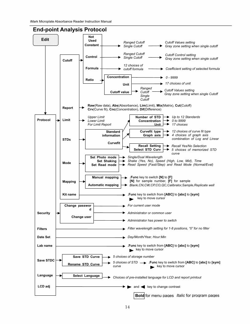
iMark Microplate Absorbance Reader Instruction Manual
15
Kinetic Protocol Reports Four types of Kinetic protocol reports can be generated absorbance kinetic plots linear regression and GALT reports
1 Absorbance Report The Kinetic Absorbance report is the series of absorbance data in the kinetic sequence
2 Kinetic Plots Report The Kinetic plots are the absorbance plots of each well in the plate It is available for readers with the optional internal printer or with an external ESCP printer which accepts ESCP code
3 Linear Regression Report The Linear Regression report provides the calculation of Kinetic reaction rate for each well using the linear regression
4 GALT Report The GALT report calculates the following formula for each well between two readings of a plate
GALT = (R2 ndash R1) k
Where R1 = Absorbance value of 1st reading
R2 = Absorbance value of 2nd reading
k = GALT factor
iMark Microplate Absorbance Reader Instruction Manual
16
Func key to switch from [ABC] to [abc] to [sym] key to move cursor
Func key to switch from [ABC] to [abc] to [sym] key to move cursor
Func key to switch from [ABC] to [abc] to [sym] key to move cursor
DayMonthYear HourMin
Filter wavelength setting for 1-8 positions ldquo0rdquo for no filter
Edit
Kinetic Analysis Protocol
Protocol
Security
Filters
Date Set
Lab Name
Change password
Change user
LockUnlock
Mode
Report
Calc
Mapping
Assay
Kit name
Reading Inter
Shaking Phmode
Speed
Number of reads (2-30) start delay time (0-999) Reading interval time Shake (FirstEverydisable) Speed (High Low Mid) Time Single Dual wavelength Read Speed (FastStep)
CC Limit (correlation coefficient limit) Calcrange (calculation range of reading number) for Linear regression Report
GALT factor k input (0- 9999) Result = (2nd read ndash 1st read)k for GALT Report
Manual mapping
Automatic mapping
Func key to switch [N] to [F] [N] for sample number [F] for sample type
General Kinetic or GALT assay assay type selection
Absorbance KINETIC Plots Linear regression when General Kinetic Assay selected GALT report when GALT Kinetic assay selected
For current user mode Administrator or Common user Administrator has power to switch
Special Buttons
Memory Recall
Main
Protocol Plate Data
Report Protocol
End point Kinetic
Checkmark
1-64 End point protocol storage 1-2 Kinetic protocol storage Checkmark reader test
Printout
Returns to MAIN screen
SaveSTDC
Language
BlankCNCWCPCOQCCalibratorSampleReplicate well
Save STD Curve
Rename STD Curve
Select Language
5 choices of storage number
5 choices of STD curve
Choices of pre-installed language for LCD and report printout
Bold for menu pages
LCD adj and key to change contrast
Italic for program pages
iMark Microplate Absorbance Reader Instruction Manual
17
Screen by Screen Procedures Initial Startup
01Kinetic-1 M405(1)R605(6)30read Shake999sMidEvery 382402 180901
End point mode
Kinetic mode
Self-diagnosis iMark Microplate Reader 1305 180901
System Login User Administrator Password Press ENTER
Login SCREEN
01EndPoint Assay01 M405(1)R655(6) Shake999sMid 382402 180901
Checkmark Validation Program
180901
Checkmark mode
Initializing reader
MAIN SCREEN
Self-Diagnosis This screen will appear upon power-up and during self-diagnosis Date and time are also indicated on this screen
Initialization After self-diagnosis the system initializes all the hardware
Security Check The system requires a password to confirm that the user is the authorized operator Pressing the ChangeRight arrow key will switch the user mode between Common user and Administrator Password for both Common user and Administrator is set as ldquo00000rdquo upon factory shipment Operator can change the password in the EDIT menu See Security
System Ready When this MAIN screen is on the LCD the StartStop key can be pressed for microplate reading Pressing StartStop key will begin reading with the current protocol There are three kinds of MAIN screens depending on the current protocol type Endpoint Kinetic and Checkmark program The four arrow keys Numeral keys Main key and Enter key are inactive StartStop Memory Recall Edit Print and Paper Feed keys are active
01EndPoint Assay01 M405(1)R655(6) Shake999sMid
180901
Kit name for current active protocol
01Kinetic-1 M405(1)R605(6)30read Shake999sMidEvery 382402 180901
Kinetic M Measurement wavelength and its position in the filter disk R Reference wavelength and its position in the filter disk Number of reading for KINETIC
Storage number in memory of current active protocol
Plate shaking parameters period in seconds and speed
M Measurement wavelength and its position in the filter disk R Reference wavelength and its position in the filter disk
Date (day month year)
Plate shaking parameters Period in seconds Speed (fast middle slow) Mode (before every read before first read and no shake)
End point
iMark Microplate Absorbance Reader Instruction Manual
18
Configuring the System NOTE To return to the previous screen use the backleft arrow key
Edit Menu
Security function raquoChange Password bullChange user bullLockUnlock Prtl
Change Password
LockUnlock
Change user
Change Password Current New Common user
Security for current active Protocol [Lock] Unlock
System Login User Administrator Password Press ENTER
Change Password Select ldquoChange Passwordrdquo in the Security Menu Enter the current password then move the cursor to the 3rd line and enter a new password Press Enter to complete the field entry The system will return to the previous Security Menu Change User Mode Select ldquoChange userrdquo in the Security Menu Select a desired user mode by pressing the Right Arrow key Enter the appropriate Password for the selected user mode Press Enter to complete the field entry The system will return to the previous Security Menu LockUnlock Protocol Select ldquoLockUnlock Prtlrdquo in the Security Menu Move the selected mark ldquo[ ]rdquo to the desired position Lock or Unlock using the Right Arrow key Press Enter to complete the field entry The system will return to the previous Security Menu If ldquoLockrdquo is selected the current active protocol will be protected against modification made by a Common user If ldquoUnlockrdquo is selected the current active protocol can be modified by any user mode NOTE Only the Administrator has authority to lock and unlock the Checkmark Protocol
Edit Menu This menu can be accessed by pressing the Edit key in the MAIN SCREEN
Security Menu Security Setting Select ldquoSecurityrdquo in the Edit Menu screen and press Enter The Security Menu appears on the screen
raquoProtocol Labname Security SaveSTDC Filters Language Date set LCD adj
iMark Microplate Absorbance Reader Instruction Manual
19
1400nm 5650nm 2450nm 6nm 3475nm 7nm 4650nm 8nm
Filter
DayMonthYear 16 05 01 Hour Minutes 18 55
Date set
Enter Lab name Bio Rad Laboratories uarr [ABC]
Lab name
Filter Setting Move the cursor to the desired position by using the Up Down and Right arrow keys Enter the filter wavelength on the selected position using the number keys If the selected position of the filter disk is empty enter three ldquordquo Press Enter to complete the field entry The system will return to the previous Edit Menu screen
Calendar Setting Move the cursor to the desirable position for date or time input by using the Up Down and Right arrow keys Enter the present date or time using the number keys Press Enter to complete the field entry The system will return to the previous Edit Menu screen
Lab Name Setting Use the Up and Down arrow keys to select from ldquoArdquo to ldquoZrdquo and symbols Use the Number keys for numeric input Use the Right arrow key to move the cursor to the right Use the Left arrow key to return the cursor to the Edit Menu screen Pressing the FUNCrdquo key will toggle the character mode between Upper case alphabet Lower case alphabet and symbol The current character mode is indicated on the lower right corner of the LCD
Save STD Curve gt Save STD Curve Rename STD Curve
Save STDC Save STDC Setting Select ldquoSave STDCrdquo in Edit Menu screen above and press Enter The Save STD Curve Menu appears on the screen Move the cursor to the desired position by using the Up and Down arrow keys
Select STD storage gt 1120304 1500 2 3150304 1030
Select for renaming gt 1160304 1125 2 3150304 1030
Save STD Curve To save a STD Curve select the storage number between 1 and 5 Use the Up and Down arrow keys to move the cursor to the desired storage number and press Enter to complete the selection After the storage number selection the rdquoAre you surerdquo message appears Select ldquoYesrdquo or ldquoNordquo and press Enter In case of ldquoYesrdquo the reader saves the STD Curve and returns to the Edit Menu screen If the curve fit calculation is not done or has not finished successfully an error message will appear and the STD Curve will not be saved STD curve does not
exist yet Press any key
Save STD Curve 1160304 1125 Are you sure gt Yes No
Rename STD Curve To change a name of an STD Curve select a storage number between 1 and 5 Use the Up and Down arrow keys to move the cursor to the desired storage number and press Enter to complete the selection Use the Up and Down arrow keys to select from ldquoArdquo to ldquoZrdquo and symbol Use the Number keys for numeric input Use the Right arrow key to move the cursor to the right Use the Left arrow key to return the cursor to the Edit Menu screen Pressing the FUNCrdquo key will toggle the character mode between Upper case alphabet Lower case alphabet and symbol The current character mode is indicated on the lower right corner of the LCD
1160304 1125 gtSTD Curve 1 lt
[ABC]
Save STD Curve
Rename STD Curve
iMark Microplate Absorbance Reader Instruction Manual
20
Printing Reports and Protocol information
Print menu raquoReports bullProtocol
Print Menu Print Menu Access this menu screen by pressing the Print key in the MAIN screen Printing Reports Select ldquoReportsrdquo and press Enter to print the current active plate data report Printing Protocol Information Select ldquoProtocolrdquo and press Enter to print all parameter settings in the current active protocol Stop Printing Press the StartStop key during printing to stop the print job immediately When printing is completed the system automatically returns to the MAIN screen
Select Language raquoEnglish bull bull bull
Language Changing Language Select a desired language using the Up and Down arrow keys and press Enter to complete the selection The system will generate a message for an immediate power off to restart Select ldquoYesrdquo and press Enter to activate the selected new language The newly-changed language will be applied to the LCD screen and printed reports Power off
gtgtYes No
LCD Contrast 12345678901234567890
laquo 26 raquo ENTER to complete
Adjusting LCD Contrast Adjust LCD contrast by using the Right and Left arrow keys and press Enter to complete the adjustment
LCD adj
iMark Microplate Absorbance Reader Instruction Manual
21
Memory Recall Operation
01 200500 1400 02raquo210500 1700 03 200500 1800 darr04raquo200500 1900
01raquo200500 0900 02raquo200500 1000
Memory Recall raquoProtocol bullPlate Data
Protocol type menu
Data type menu
End Point
Kinetic
End Point
Kinetic
Memory Recall Menu
Select protocol type raquoEnd Point
bullKinetic bullCheckmark
Select Protocol 02 uarrraquo Protocol -2 Protocol -3 darr Protocol -4
Select Protocol 01 raquo Kinetic -1 GALT
Select data type raquoEnd Point
bullKinetic bullCheckmark
200501 0900
Checkmark
Checkmark program has been activated Press any key
Checkmark
Selecting Protocol Move the cursor to the position of the desired protocol and press Enter to complete the selection NOTE ldquordquo indicates the currently activated protocol and ldquordquo indicates a security locked protocol There is no protocol selection with ldquoCheckmarkrdquo When a protocol is selected the system will then automatically return to the MAIN screen
Changing Current Active Protocol Select ldquoProtocolrdquo in Memory Recall menu above and press Enter The Select Protocol type menu will appear on the screen Select a protocol using the Up and Down arrow keys Press Enter to complete the selection
Selecting Plate Data Move the cursor to the position of the desired plate data and press Enter to complete the selection NOTE ldquordquo indicates the currently activated plate data There is only one storage for ldquoCheckmarkrdquo data When plate data is selected the system automatically returns to the MAIN screen
Changing Current Active Plate Data Select ldquoPlate Datardquo using the Memory Recall button and press Enter The Data type menu will appear Use the Up and Down arrow keys to select a plate data type Press Enter to complete the selection
This menu screen can be accessed by pressing the Memory Recall key in the MAIN screen
iMark Microplate Absorbance Reader Instruction Manual
22
Editing the Kinetic Protocol
Select ldquoProtocolrdquo in the Edit Menu and press Enter The Kinetic Protocol menu will appear on the screen if the current active protocol type is Kinetic
Reading speed [Fast mode] Step mode
Speed
raquoReading Speed Inter Shaking Phmode
Kinetic Mode
Kinetic Protocol Menu
raquoMode Report Calc Kit name Mapping Assay
This menu screen can be accessed by selecting ldquoModerdquo in the Kinetic Protocol menu above
Number of Reading = 20 (2-30) Start Delay time = 25 sec(0-999)
Reading
Number of Reading = 2 Start Delay time = 25 sec(0-999)
Number of Readings and Start Delay Time Setting Press the Up or Down arrow key to change the number Enter the appropriate numbers with the numeral keys and press Enter to complete the field entry The system will return to the Kinetic Edit Menu If GALT is the current assay type the number of reading fields is fixed at 2 Press the StartStop key to set the Start Delay time enter a value and press Enter until the reading starts
1-gt2raquo 100 sec 2-gt3 100 sec 3-gt4 100 sec darr4-gt5 100 sec
Inter Use same interval between all reads
raquoYes No
Setting Reading Intervals The system prompts the operator to set a reading interval before each plate run Move the cursor to the desired selection ldquoYesrdquo or ldquoNordquo and press Enter The system generates the interval entry screen Move to the active entry field by pressing the Up and Down arrow keys and enter appropriate numbers using numeral keys Press Enter to complete all field entries The system will return to the Kinetic Mode menu
Photometric Dual Measurement405 nm Reference 655 nm
Ph mode Photometric Mode Setting When the ldquoPhotometricrdquo field is activated pressing the Right arrow key will switch the field entry ldquoSinglerdquo lt-gtrdquoDualrdquo Pressing the Up or Down arrow keys will move the cursor to the next entry field Pressing the Right arrow key when the wavelength field is activated will change the wavelength to the next available selection installed in the reader Press Enter to complete all field entries
Shaking parameters Before Every read Speed Mid Time 999 sec
Shaking Plate Shake Parameters When the ldquoBeforerdquo field is activated pressing the Right arrow key will change the field entry ldquoEveryrdquo-gtrdquo--rdquo-gtrdquoFirstrdquo-gt When the ldquoSpeedrdquo field is activated pressing the Right arrow key will change the field entry ldquoMidrdquo -gtrdquoHirdquo-gtrdquoLowrdquo-gt When the ldquoTimerdquo field is activated enter the time value for plate shaking period using the numeral keys Press Enter to complete all field entries
Selecting Reading Speed Use the Up or Down arrow keys to switch the selection Press Enter to complete the selection
Edit Menu raquoProtocol Labname Security bullSaveSTDC Filters bullPrinter Date set
This menu screen can be accessed by pressing the Edit key in the MAIN screen
iMark Microplate Absorbance Reader Instruction Manual
23
Kit name for 01 raquoGAP TEST IgGlaquo uarr [ABC]
Kit name
Calculation
Mapping
Assay
Assay type selection raquo[General KINETIC] GALT assay
Calculation Param CC Limit 0910
Calcrange 10 - 20
Select Mapping mode raquoManual mapping bullAutomatic mapping
raquo[Linregression] bullAbsorbance bullKINETIC Plots
Report
Plate Mapping See Plate Map setting procedure
Result = (R2 ndash R1)k k = 999999 R11st Reading R22nd Reading
If GALT
Setting the Kit Name Use the Up and Down arrow keys to select alphabet from ldquoArdquo to ldquoZrdquo and space Use the Number keys for numeric input Use the Right arrow key to move the cursor to the right Use the Left arrow key to return to the Protocol Menu screen Pressing ldquoFUNCrdquo key will change the character mode Upper case alphabet -gt Lower case alphabet -gt symbol The current character mode is indicated on the lower right corner of the LCD
Kinetic Protocol Menu
Selecting Kinetic Assay Type Move the cursor to the desired Assay type by pressing the Up or Down arrow keys Press Enter to complete the selection The item with mark ldquo[ ]rdquo is the currently selected item GALT assay Result = factor x (2nd Read ndash 1st Read)
Selecting Report Type Move the cursor to the desired report type by pressing the Up or Down arrow keys Pressing the Right arrow key will select or deselect the item Press Enter to complete the selection Note When GALT assay is selected ldquoGALT reportrdquo shall be the only one option on this screen
raquoMode bullReport bullCalc bullKit name bullMapping bullAssay
Calculation Parameter Setting When the ldquoCC Limitrdquo field is activated pressing the numeral key will enter the desired numbers Press Enter to complete all field entries If the GALT Reports is activated pressing the numeral keys will enter the desired numbers Press Enter to complete all field entries
iMark Microplate Absorbance Reader Instruction Manual
24
Checkmark Value Setting (Administrator only)
raquoSerial Report bullLinearity ref bullMaxCV bullFilter Check ref
Checkmark Protocol Menu
raquoSerial 0000 Reptype Simple
405nm S10158 Linearity S20309 reference S31401 S42109
MaxCV raquoS115 Linearity S205 reference S302 S402
Filter max min 4051875 0329 4501167 0954 darr 4920596 0103
Serial Report
Linearity reference
Max CV
Filter check reference
Filter max min uarr 5401875 0329 6201167 0954 6900596 0103
Setting the Serial Number and Report Type Pressing the Up and Down arrow keys will move the cursor and change the field entry When ldquoSerial rdquo field is active enter the serial number that will be shown in the data sheet of the Checkmark plate using the numeral keys When the ldquoRep typerdquo field is active pressing the Right arrow key will switch the report type between ldquoSimplerdquo and ldquoFullrdquo
Setting the Linearity Reference Value Pressing the Up or Down arrow keys will move the field entry from S1 to S4 Pressing the Right arrow key will change the wavelength 405 nm-gt450 nm-gt492 nm-gt540 nm-gt620 nm-gt690 nm Use the numeral keys for the reference value setting Pressing Enter will complete all field entries at all wavelength
Max CV setting Pressing the Up or Down arrow keys will move the field entry from S1 to S4 Use the numeral keys for the Max CV setting Press Enter to complete all field entries
Setting the Filter Check Reference Value Initial screen shows the reference entries for 405 nm to 492 nm and pressing the Down arrow key at the bottom of the screen entries will scroll to the next page for 540 nm to 690 nm Pressing the Up Down and Right arrow keys will move the field entry Use the numeral keys for the filter check reference value setting Press Enter to complete all field entries
Select ldquoProtocolrdquo in the Edit Menu and press Enter The Checkmark Protocol Menu will appear on the screen if the current active protocol type is Checkmark mode
Edit Menu raquoProtocol bullLabname bullSecurity bullSaveSTDC bullFilters bullPrinter bullDate set
This menu screen can be accessed by pressing the Edit key in the MAIN screen
iMark Microplate Absorbance Reader Instruction Manual
25
Editing End Point Protocol
Upper Limit= 2000 Lower Limit= 0000 input range 0ndash3500 Upper gt Lower
Standard menu raquoSTD information
bullCurvefit bullRecall STD Curve
raquoCutoff bullMode bullReport bullMapping bullLimit bullKit name bullSTDs
Cutoff
See Plate Map setting procedure
See Standard setting procedure
See Mode setting procedure
raquo[Not use] bullRatio bullConstant bullContrl bullFormula
raquoSet photo mode bullSet shaking bullSet read mode
Select mapping mode raquoManual mapping bullAutomatic mapping
Mapping
Mode
Report
STDs
Limit
Kit name for 01 raquoGAP TEST IgGlaquo uarr [ABC]
Kit name See Kit name setting in Editing Kinetic Protocol
See Cutoff setting procedure
Select ldquoProtocolrdquo in Edit Menu screen above and press Enter The End point Protocol Menu will appear on the screen if the current active protocol type is End point mode
End Point Protocol Menu
raquo[Raw] bullMtx bullCnc bullAbs bullCut bullDif bullLim bullCrv
If ldquoDifrdquo selected
[Raw] bullMtx bullCncbullAbs bullCut [Dif] bullLim bullCrv raquorow odd-even
Seting the Report Type Use the Up and Down Arrow key to move the cursor and press the Right Arrow key to select or deselect the report type Selected report type is marked as ldquo[ ]rdquo Press Enter to complete the selection
Setting the Limit Value Use the Up and Down Arrow key to move the cursor and enter the OD value using the numeral keys The OD value range is 0000 - 3500 Press Enter to complete the selection
Edit Menu raquoProtocol bullLabname bullSecurity bullSaveSTDC bullFilters bullPrinter bullDate set
This menu screen can be accessed by pressing the Edit key in the MAIN screen
iMark Microplate Absorbance Reader Instruction Manual
26
Cutoff Setting Procedure
Cutoff Setting Menu This menu is entered by choosing Cutoff in the End Point Protocol Menu It is used to set the cutoff type The cutoff type marked with ldquo[ ]rdquo is the current selection The Up and Down arrow keys move the cursor to the desired item in the menu list When the desired parameters have been selected press Enter twice to accept the selection and to continue to the next screen Not use means that the reader does not generate the cutoff report Four types of cutoff are supported
1 Cutoff Constant 2 Cutoff Control 3 Cutoff Formula 4 Cutoff Ratio
a Cutoff Constant
Selection of SingleRanged Cutoff Constant This menu selects Single or Ranged cutoff type The cutoff type marked with ldquo[ ]rdquo is the current selection The Enter key seals the selection and resumes to the next setting screen
Single Cutoff Constant The Numerical keys and the Decimal point key are used to enter the positive and gray zone values The Right arrow key is used to select the unit The Up and Down arrow keys move the cursor to the desired parameter of the single cutoff The Enter key sets all values and selection of the cutoff constant and returns the user to the previous screen Ranged Cutoff Constant The Numerical keys and the Decimal point key are used to enter the positive and negative values The Right arrow key is used to select the unit The Up and Down arrow key moves the cursor to the desired ranged cutoff parameters The Enter key sets all values and selection of the cutoff constant and returns to the previous screen NOTE Two available Cutoff constants are ldquoAbsorbancerdquo and ldquoConcentrationrdquo If Abs is chosen the Absorbance cutoff will be done with the cutoff constant parameters defined and the absorbance report is generated For other units defined in the curve fit setting the Concentration value using the curve fit and then cutoff is done with the cutoff constant parameters defined and the concentration value of each well It is necessary to set the curve fit parameters
raquoNot usex bullRatio [Const] bullContrl bullFormula
raquoPositive gt= 9999 Gray zone 50 Unit moll
raquoPositive gt= 9999 Negative lt 1999 NegativeltPositive Unit moll
raquoRanged cutoff [Single cutoff]
Single cutoff
Ranged
iMark Microplate Absorbance Reader Instruction Manual
27
b Cutoff Control
Selection of SingleRanged Cutoff Control This menu screen selects Single or Ranged cutoff type The cutoff type marked with ldquo[ ]rdquo is the current selection The Enter key seals the selection and resumes to the next setting screen
Single Cutoff Control The Numerical keys are used to enter the gray zone value The unit is fixed to Abs The Enter key sets the value of the cutoff control and returns to the previous screen Ranged Cutoff Control There is no parameter to set for the ranged cutoff control The Enter key returns to the previous screen NOTE CNx is the mean absorbance value of Negative control wells and CPx is the mean absorbance value of Positive control wells These wells are defined in the plate map setting The cutoff is done with the Positive and Negative value to the absorbance value of each well
c Cutoff Formula
Selection of Formula This menu screen selects a formula for cutoff calculation The formula marked with ldquo[ ]rdquo is the current selection The Up and Down arrow keys move the cursor to the desired formula type The movement of the cursor follows the scroll of this screen The Enter key marks the selection and advances the user to the next setting screen The supported formula types are
1 k CNx 2 k CPx 3 k COx 4 CNx k 5 CPx k 6 COx k 7 k + CNx 8 k + CPx 9 k + COx 10 kCNx + CPx 11 ( CNx + CPx ) k 12 k1CNx + k2CPx
Coefficient for Cutoff Formula 1 to 11 The Numerical keys and the Decimal point key are used to enter the coefficient k and gray zone values The Up and Down arrow key moves the cursor to the desired parameter of the cutoff formula The Enter key sets all values of the cutoff formula and returns to the previous screen
Positive gt= CNx Gray zone 50 Unit Abs
Positive gt= CPx Negative lt CNx Unit Abs
Enter key to accept
raquoRanged cutoff [Single cutoff]
Single cutoff
Ranged
Input coefficient k = 001 (001-10) Gray zone 50(0-99)
k CNx k CPx k COx CNx k CPx k COx k k + CNx k + CPx k + COx k CNx + CPx (CNx + CPx) k
uarr raquoCNx k bullCPx k bullCOx k darr bullk + CNx
Select formula raquo[kCNx ] bullkCPx darr bullkCOx
uarr raquok + CPx bullk + COx bullkCNx + CPx darr bull(CNx + CPx) k
uarr raquok1CNx + k2CPx
Page-1
Page-2
Page-3
Page-4
iMark Microplate Absorbance Reader Instruction Manual
28
Coefficient for Cutoff Formula 12 The Numerical keys and the Decimal point key are used to enter the coefficient k1 and k2 and gray zone values The Up and Down arrow key moves the cursor to the desired cutoff formula The Enter key sets the all values of the cutoff formula and returns to the previous screen NOTE CNx is the mean absorbance value of Negative control wells CPx is the mean absorbance value of Positive control wells and COx is the mean absorbance value of Cutoff control wells These wells are defined on the plate map setting The cutoff value is calculated using the defined formula with the defined values and coefficients
d Cutoff Ratio
Ratio to Calibrator In this screen there are three items for setting the ratio to calibrator The Up and Down arrow key moves the cursor to the desired item in the menu list The Enter key seals the selection and resumes to the next setting screen
Concentration of Calibrator The Numerical keys and the Decimal point key are used to enter the calibrator concentration value The Enter key sets the value and returns to the previous screen Unit of Calibrator Seventeen standard units are supported The unit marked with ldquo[ ]rdquo is the current selection The setting procedure is the same as the unit selection of Standards Cutoff Value Setting This menu screen selects Single or Ranged cutoff type The cutoff type marked with ldquo[ ]rdquo is the current selection The Enter key marks the selection and continues to the next setting screen Single Cutoff Control The Numerical keys are used to enter the Positive cutoff concentration value and gray zone value The Enter key sets these cutoff ratio values and returns to the previous screen Ranged Cutoff Control The Numerical keys are used to input the Positive and the Negative cutoff concentration values The Enter key sets these cutoff ratios and returns to the previous screen NOTE The calibrator concentration value is used to convert the absorbance value of each well into a concentration value The ratio of ConcentrationAbsorbance of Calibrator well is applied to the conversion The cutoff uses defined Positive and Negative values to the converted concentration value of each well
Input coefficient k1 = 001 (001-10) k2 = 100 (001-10) Gray zone 50(0-99)
k1 CNx + k2 CPx
Ratio to Calibrator raquoConcentration bullUnit bullCutoff value
Concentration 9999 unit moll
uarrraquo 01 ugdl 02 ngml 03[ pgml] darr 04 pmml
raquoPositive gt= 9999 Gray zone 50
Unit moll
raquoPositive gt= 9999 Negative lt 9999 NegativeltPositive
Unit moll
raquoRanged cutoff [Single cutoff]
Concentration
Unit
Cutoff value
Single cutoff
Ranged cutoff
iMark Microplate Absorbance Reader Instruction Manual
29
Standard Setting Procedure
Standard Curve Setting Menu This menu screen is entered by choosing STDs in the End Point Protocol Menu screen It is used to set the concentration data and the curve fit type for a standard curve or to recall a memorized standard curve The Up and Down arrow key moves the cursor to the desired item in the menu list The Enter key seals the selection and continues to the next setting screen
a STD Information Setting
STD Information In this screen there are three items for setting the concentration data of standards The Up and Down arrow keys move the cursor to the desired item in the menu list The Enter key seals the selection and continues to the next setting screen
Number of Standards The Numerical keys are used to enter the number of standards ldquo0rdquo means that the curve fit report is not used The Enter key sets the number and returns to the previous screen The maximum number of standards is 12 Concentration The Numerical keys and the Decimal point key are used to enter the concentration values of standards The Up and Down arrow keys move the cursor to the desired position The movement of the cursor also follows the scroll of this screen The Enter key sets all values of the concentration of standards and returns to the previous screen Unit Seventeen units are supported The unit marked with ldquo[ ]rdquo is the current selection The Up and Down arrow keys move the cursor to the desired unit type The movement of the cursor also follows the scroll of this screen Press Enter twice to select the unit type and to return to the previous screen The supported types of unit are
1 moll 11 pgml 2 m moll 12 Uml 3 u moll 13 IUml 4 n moll 14 uIUml 5 p moll 15 mIUml 6 mgl 16 EU 7 ngl 17 Arbit 8 pgl 9 ugdl 10 ngml
STD information raquoNumber of STD bullConcentration bullUnit
STD 1 0512 STD 2 1012 STD 3 1512 darr STD 4 2053
Standard menu raquoSTD information bullCurve fit bullRecall STD curve
Concentration
Number of STD
Number of STD = 05 (0 2ndash12)
uarrraquo 01 ugdl 02 ngml 03[ pgml] darr 04 pmml
Unit
iMark Microplate Absorbance Reader Instruction Manual
30
b Curve Fit Setting
Curve Fit In this screen there are two choices to set the curve fit The Up and Down arrow keys move the cursor to the desired item in the menu list The Enter key seals the selection and resumes to the next setting screen
Curve Fit Type 10 types of curve fit are supported as below The curve fit type marked with ldquo[ ]rdquo is the current selection The Up and Down arrow key moves the cursor to the desired curve fit type The movement of the cursor follows the scroll of this screen Press Enter twice to select the unit type and to return to the previous screen The supported curve fit types are
1 5P Logistic Rodbard 2 4P Logistic Rodbard 3 5P Logistic Cook-Wilkenson 4 4P Logistic Cook-Wilkenson 5 5P Exponential 6 Sigmoid Logistic 7 Linear regression 8 Quadratic regression 9 Cubic 10 Point To Point regression
Graph Axis Four types of graph are supported The curve fit type marked with ldquo[ ]rdquo is the current selection The Up and Down arrow keys move the cursor to the desired graph type Press Enter twice to select the unit type and to return to the previous screen The supported graph types are
1 Log - Log 2 Log - Linear 3 Linear - Log 4 Linear - Linear
uarr 5p logisticRodb raquo 4p logisticRodb [5p logisticCook] darr 4p logisticCook
raquo X-Log Y-Log [X-Log Y-Lin] X-Lin Y-Log X-Lin Y-Lin
Curve fit type
Graph axis
Curve fit setting raquoCurve fit type bullGraph axis
iMark Microplate Absorbance Reader Instruction Manual
31
c Recall STD Curve Setting
Recall Setting of Standard Curve In this screen there are two items for setting the Recall STD curve as below The Up and Down arrow keys move the cursor to the desired item in the menu list
1 Recall setting (YesNo) 2 Selecting the storage number of standard curves (1 -gt 5)
Recall Setting Move the cursor to the desired position using the Up Down or Right arrow keys Enter key accepts the setting and returns the user to the standard menu screen
Yes Recalling of the standard curve is active No Recalling of the standard curve is inactive
Storage Number Selection Five memories are selectable The vacant memory (marked with asterisks on the date and time field) is also selectable It is necessary to save a standard curve before using its protocol Move the cursor to the desired position using the Up and Down keys This setting screen consists of two parts The Right arrow key is used to switch the indication field between the date and time to the standard curve name Move the cursor to the desired position using the Up and Down keys The Enter key accepts the storage number and returns to the standard menu screen NOTE If the recall of standard curve is active (the recall setting is ldquoYesrdquo) the standard information setting and the curve fit setting will be invalidated and their setting screens will not open
Recall STD curve raquoRecall setting bullSelect STD curve
Recall setting raquoYes No
Recall setting
Select STD Curve raquo1160304 1125
2 darr 3150304 1030
Select STD Curve uarrraquo4
5
Select STD Curve raquo1 STD Curve 1
2 STD Curve 2 darr 3 STD Curve 3
Select STD Curve uarrraquo4 STD Curve 4
5 STD Curve 5
Select STD curve
Right arrow key
iMark Microplate Absorbance Reader Instruction Manual
32
Mode Setting Procedure
Mode Setting Menu This menu screen is entered by choosing the Mode in the End Point Protocol Menu screen or the Kinetic Protocol Menu screen It is used to set the plate reading conditions The Up and Down arrow keys move the cursor to the desired item in the menu list The Enter key seals the selection and resumes to the next setting screen
a Set Photo Mode
Photo Mode In this screen the user chooses Single or Dual wavelength measurement and assigns the measurement and reference (for dual wavelength measurement) filters The assignment of the reference filter appears for dual wavelength measurement The Up and Down arrow keys move the cursor to the desired parameter The Right arrow key chooses SingleDual wavelength measurement and selects the installed filter on the Filters of Edit Menu screen The Enter key seals the selection and returns to the previous screen
b Set Shaking
Shaking In this screen the user selectsdeselects shaking function sets the shaking strength and enters the shaking time A shaking time of 0s indicates no shaking The maximum shaking time is 999 seconds The Up and Down arrow key moves the cursor to the desired parameters The Right arrow key toggles between YesNo (SelectDeselect) shaking or selects strength LowMiddleHigh The Numerical keys are used to enter the shaking time The Enter key seals the selection and returns the user to the previous screen
c Set Read Mode
Read Mode In this screen the user chooses Fast or Step reading and also chooses Normal or Evaluation mode The ldquo[ ]rdquoindicates the current selection The Up and Down arrow key moves the cursor to the desired parameters The Right arrow key chooses FastStep speed or chooses NormalEval mode The Enter key seals the selection and returns to the previous screen The followings are the description of each read mode parameter Reading speed
Fast reading 6 secsingle wavelength reading 10 secdual wavelength reading
Step reading 15 secsingle wavelength reading 30 secdual wavelength reading
Reading mode
Normal mode Plate reading once Evaluation mode Four plate readings per one of measurement are performed and
the average data of their plate readings is generated as a plate data
Photometric Dual Measurement400 nm Reference 655 nm
Set Shake parameters ShakeYes SpeedMid Time 199sec(0-999)
raquoReading speed [Fast ] Step bullRead mode [Normal] Eval
raquoSet Photo mode bullSet shaking bullSet read mode
Photometric Single Measurement400 nm
iMark Microplate Absorbance Reader Instruction Manual
33
Plate Map Setting Procedure
Select Mapping Mode Menu This menu screen is entered by choosing Mapping in the End Point Protocol Menu screen or the Kinetic Protocol Menu screen It is used to map the plate format The Up and Down arrow keys move the cursor next to the desired item of menu list The Enter key seals the selection and changes this screen to the next setting screen
a Manual Mapping
Manual Mapping In this screen the user can set the plate format manually Ten well types can be set Well types The supported well types are
Well type Indication on LCD
1 Blank B 2 Sample X00hellipX99 3 Standard S01hellipS99 4 In-kit Control Positive Control CP0hellipCP9 5 Weak Positive Control CW0hellipCW9 6 Negative Control CN0hellipCN9 7 Cutoff Control CO0hellipCO9 8 Calibrator CL0hellipCL9 9 QC Control QC0hellipQC9 10 Empty well -
The key assignments of well type are ldquo0EMPrdquo Empty well ldquo5QCrdquo Quality Control well ldquo1SMPrdquo Sample well ldquo6CALrdquo Calibrator well ldquo2BLKrdquo Blank well ldquo7CPrdquo Positive Control well ldquo3STDrdquo Standard well ldquo8CNrdquo Negative Control well ldquo4COrdquo Cutoff Control well ldquo9CWrdquo Weak Positive Control well
Two Edit Modes in Plate Mapping There are two editing modes for well type input mode and for well number input The current input mode is displayed at the upper left corner of the screen When using the well type input mode the mode sign is ldquo[F]rdquo When using the well number input mode the mode sign is ldquoNrdquo The cursor that encloses the editing position of well has two types of enclosures depending on the mode For example ldquo[S01]rdquo accepts the well type keys that be assigned to the numerical keys and ldquoS01rdquo accepts the numerical input The mode is easily changed with the Decimal point key Key Functions The Up Down Right and Left arrow keys move the cursor to the desired well The movement of the cursor follows the scroll of this screen The Left arrow key will return the screen to the preceding screen or the select Mapping mode Menu only if the cursor is on column 1 At this time the selection screen appears (see the left figure) The Decimal point key changes the input mode The Numerical keys have two functions one to input the number and another to select a well type The Enter key checks the consistency between the edited plate map and other parameters memorizes the plate map into the protocol and changes this screen back to the preceding screen If it finds any inconsistency a warning message will appear on the screen
Select Mapping mode raquoManual mapping bullAutomatic mapping
N 1 2 3 4 A B CN1 S01 S01 B B CN1 S02 S02 C B CN2 S03 S03 [F] 5 6 7 8 A X11 X12 X13 X14 B X21 X22 X23 X24 C X31 X32 X33[X34]
Discard change 1Yes 2No Press 1 or 2 key
iMark Microplate Absorbance Reader Instruction Manual
34
Acceptable Number Ranges for each well type 1 Blank and Empty wells do not use numbers 2 Sample and Standard wells 00 - 99 3 Standard wells 01 - 99 4 Control and Calibrator wells 0 - 9
b Automatic Mapping
Automatic Mapping The user can input the number of each well type in this screen These defined numbers are used to set a plate map automatically Well type Nine well types are available
1 BLK Blank (0-gt10) 2 CN Control CN (0-gt9) 3 CW Control CW (0-gt9) 4 CP Control CP (0-gt9) 5 CO Control CO (0-gt9) 6 QC Control QC (0-gt9) 7 CAL Calibrator (0-gt9) 8 SMP Sample (0-gt96) 9 REP Replicate well (1-gt4)
It is possible to define the number of blanks samples calibrators and controls But the number of Standards is not included because standards are defined at the Standard Setting Menu The number of replicate wells is also included It is used for replicating each well type individually Key Functions The Up Down Right and Left arrow keys are used to move the cursor to the next position The Numerical keys are used to input the mapping parameters The Enter key accepts the mapping parameters and sets a plate map automatically using these parameters During the execution of the plate mapping the Plate auto-mapping completed message appears on the screen After that the user returns automatically to the previous Protocol Menu screen If the Left arrow key is pressed at the left end position of the cursor the left figure will appear on the screen If the user chooses Yes the system will return to the previous Protocol Menu screen If the user chooses No the system will stay in this setting screen Assigning Order and Direction of plate mapping Assigning Order The order of blanks standards samples calibrators and controls are fixed as follows Numbering for standards samples calibrators and controls is started at 1
1 Blank 2 Standard 1 -gt12 ---- NOTE 3 Control CN 1-gt9 4 Control CW 1-gt9 5 Control CP 1-gt9 6 Control CO 1-gt9 7 Control QC 1-gt9 8 Calibrator 1-gt9 9 Sample 1-gt96 10 Empty well NOTE If ldquoCutoff Controlrdquo ldquoValue by Formulardquo or ldquoRatio to Calibratorrdquo is
selected for the Cutoff plate mapping skips arranging the standards Assigning Direction The placing direction of the mapping is limited to the column direction as below
Column direction A1 -gt H1 A2 -gt H2 ----- A12 -gt H12
Discard change 1Yes 2No Press 1 or 2 key
Automatic mapping BLK= 1 CP = 1 CAL= 0 CN = 1 CO = 0 SMP=93 CW = 0 QC = 0 REP= 1
Plate auto-mapping completed
iMark Microplate Absorbance Reader Instruction Manual
35
Warning and Error of Automatic Mapping Warning screen If the total number of wells mapped exceeds 96 wells a warning message in the left figure appears on the screen The calculation of the total number of mapping wells is as follows
(Blanks+Standards+CNs+CWs+CPs+COs+QCs+Calibrators+Sample)Replicates The plate mapping is executed normally and the exceeded part is invalidated Error screen If one or more mapping parameters are over the input range an error message in the left figure will appear on the screen On the third line of the LCD the name of the parameter which is out of range and its input range will appear
Example ldquoBLK 0 ndash 10rdquo In case there is more than one error the first parameter of errors is indicated By pressing any key the user returns to the automatic mapping screen Example of automatic mapping An example of automatic mapping is as below 1 Conditions of each parameter
Blank = 1 Standard = 8 Control CN = 2 CW = 0 CP = 2 CO = 0 QC = 0 Calibrator = 1 Sample = 32 Replicate number = 2
2 Plate mapping data
1 2 3 4 5 6 7 8 9 10 11 12 A B C D E F G H
B B S1 S1 S2 S2 S3 S3
S4 S4 S5 S5 S6 S6 S7 S7
S8 S8 CN1 CN1 CN2 CN2 CP1 CP1
CP2 CP2 CL1 CL1 X1 X1 X2 X2
X3 X3 X4 X4 X5 X5 X6 X6
X7 X7 X8 X8 X9 X9 X10 X10
X11 X11 X12 X12 X13 X13 X14 X14
X15 X15 X16 X16 X17 X17 X18 X18
X19 X19 X20 X20 X21 X21 X22 X22
X23 X23 X24 X24 X25 X25 X26 X26
X27 X27 X28 X28 X29 X29 X30 X30
X31 X31 X32 X32 E E E E
Warning The total Of mapped wells has Exceeded 96 Press any key
Entered value is Out of range BLK 0 ndash 10 Press any key
iMark Microplate Absorbance Reader Instruction Manual
36
Instrument Maintenance
Caution Electrical shock hazard Always disconnect the instrument from the AC power source before opening the service compartment
Caution The lamp and the lamp cover may be very hot Use caution and allow the lamp to cool
before attempting service
Installing Interference Filters 1 With the power off open the rear cover of the instrument by pressing the
release latch located on the top left portion of the cover 2 Locate the filter wheel on the left side of the instrument Note that the
filter wheel has eight filter positions 3 Rotate the filter wheel to the desired filter Grasp the top of filter frame
and pull up to remove the filter 4 Insert the new filter into the desired filter position 5 Ensure that the new filter is added to the filter list as follows Main
menu-gtEdit-gtFilters
Changing the Lamp 1 With the power off open the rear cover of the instrument by pressing the
release latch located on the top left portion of the cover 2 Remove the two screws on the black plastic cover and carefully remove
the plastic cover 3 Remove the screw on the metal cover Lift the cover up and away from
the instrument This will allow the lamp to be pulled free from the lamp housing
4 Holding the ceramic base in one hand and the lamp housing in the other carefully pull the lamp free of the base
5 Carefully insert the new lamp firmly in the ceramic base Apply even pressure when inserting the lamp so that the bulb dose not become misaligned in the reflector housing Be extremely careful not to touch the front glass of the lamp during installation
6 Position the new lamp into the housing so that the plastic guides hold the flange of the lamp
7 Carefully place the metal cover over the lamp Tighten the screw 8 Replace the plastic cover and tighten the screws 9 Close the rear cover
iMark Microplate Absorbance Reader Instruction Manual
37
Troubleshooting and Error Messages
The iMark Microplate Reader constantly monitors several functions and displays appropriate messages on the LCD as errors are encountered
Error Recommendation
LCD appears blank on power up
a Power is not turned on The AC outlet is non-functional
b Unit is not plugged into AC outlet or power code is not attached to the instrument
Check power cord connections at outlet and on the rear panel of the instrument
1
c The AC outlet is non-functional Check circuit breakers or fuses
Instrument displays ldquoLight bulb errorrdquo message indicating that the bulb is burned out
Check whether lamp is emitting light
a Lamp is not emitting light Replace the lamp as described in x
2
b Lamp is emitting light Check the alignment of the lamp in the housing Align or replace the lamp if necessary
Printer will not print on command
3
a Printer paper is not installed properly Verify that the paper is properly installed Refer to x for details
Plate carriage jams during reading and ldquoPlate carrier errorrdquo is displayed
a Plate is not seated in carriage properly Press the STOP button immediately Position the plate carefully in the carriage making certain that it is properly seated
4
b Plate height is exceeding 16mm Use Microplate which is less than 16mm in height
5 LCD displays ldquoFilter missingrdquo Install a filter in the empty position Select the installed filter by pressing Edit key
6 LCD displays ldquoFilter disk jammedrdquo indicating that the filter wheel is not turning freely
Turn off the instrument and inspect the filter wheel Turn by hand to verify that the wheel is moving freely Make sure all the filters are properly installed and firmly seated Contact your Bio-Rad representative if the filter wheel is jammed or if the problem persists
7 LCD displays ldquoFilter not installedrdquo Enter the Edit Menu by pressing Edit key and set up the filters
iMark Microplate Absorbance Reader Instruction Manual
38
Wells have color but absorbance values seem low
a Incorrect filter used for measurement andor reference wavelength
Check wavelength used in analysis Read plate in single wavelength mode at all wavelength to verify that the proper filter was used The measurement wavelength should produce the highest absorbance
b The best measurement wavelength filter for the substrate in use has not been installed in the filter wheel
Check references for the substrate you are using or determine the best measurement wavelength by analyzing the substrate product on a scanning spectrophotometer Custom filters are available from 400 to 750 nm
8
c The filters have been switched in the wheel Check that the filters are installed in the correct position
9 ldquoPrinter errorrdquo displayed Check for paper jam Install the printer paper correctly
10 ldquoBattery errorrdquo displayed The internal battery is almost dead Contact your local Bio-Rad office
11 The following messages are displayed ldquoMemory errorrdquo ldquoCalendar errorrdquo ldquoLCD hardware errorrdquo ldquoPrinter errorrdquo ldquoLight level errorrdquo ldquoDA conversion errorrdquo ldquoAD conversion errorrdquo ldquoEEPROM errorrdquo ldquoUSB errorrdquo
Contact your local Bio-Rad office if these problems persist
iMark Microplate Absorbance Reader Instruction Manual
39
Instrument Specifications Computer interface USB 20
Plate shaking 3 speeds (low mid high) Programmable time period 0 - 999 seconds
Data storage The most recent 10 data plates for end-point most recent 2 data plates of 30 readings for kinetic readings protocol data and calendarclock function shall be kept in memory by a lithium battery even when the power is off Average lifetime of the battery shall be 5 years
Warm-up time 3 minutes
Photometric Methods Single and dual wavelength
Photo detectors 8 silicon photodiodes for measurement and 1 silicon photodiode for reference
Light source Tungsten halogen lamp 20W with 3000 hours average lifetime
Spectral range 400 nm to 750 nm
Interference filters Wavelength tolerance plusmn30 nm Band width 10 nm typically
Filter capacity 8 filters
Reading speed Fast Reading 6 sec with single wavelength reading 10 sec with dual wavelength reading
Step Reading 15 sec with single wavelength reading 25 sec with dual wavelength reading
These times are minimum interval times between repetitive reads using onboard KINETIC protocol
Indication range 0000 to 35 OD
Resolution 0001 OD
Accuracy plusmn10 or 0010 from 0 to 30 OD at 490 nm
Linearity plusmn10 from 0 to 20 OD plusmn20 from 0 to 30 OD
Reproducibility 10 or 0005 OD from 0 to 20 OD 15 from 20 to 30 OD
Inter-channel variability 15 or 0005 OD from 0 to 30 OD
Stability and Drift 0010 OD at OD=1 with single wavelength reading
Built-in Printer Thermal printer Paper width 80mm
Line Voltage Universal input 100 - 240 VAC 5060Hz
Power consumption (max) 100 VA max
Dimensions (W x D x H 346 mm x 377 mm x 164 m mm
Weight 55 kg
Operating Environment 15ordmC - 40ordmC up to 90 relative humidity without condensation
Storage Temperature 10ordmC - 50ordmC up to 90 relative humidity without condensation
Life ScienceGroup
07-0816 0108 Sig 120710013301i Rev A USEG
Bio-RadLaboratories Inc
Web site wwwbio-radcom USA 800 4BIORAD Australia 61 02 9914 2800 Austria 01 877 89 01 Belgium 09 385 55 11 Brazil 55 21 3237 9400 Canada 905 364 3435 China 86 21 6426 0808 Czech Republic 420 241 430 532 Denmark 44 52 10 00 Finland 09 804 22 00 France 01 47 95 69 65Germany 089 318 84 0 Greece 30 210 777 4396 Hong Kong 852 2789 3300 Hungary 36 1 455 8800 India 91 124 4029300 Israel 03 963 6050 Italy 39 02 216091 Japan 03 6361 7000 Korea 82 2 3473 4460 Mexico 52 555 488 7670 The Netherlands 0318 540666 New Zealand 0508 805 500 Norway 23 38 41 30 Poland 48 22 331 99 99 Portugal 351 21 472 7700 Russia 7 495 721 14 04 Singapore 65 6415 3188 South Africa 27 861 246 723 Spain 34 91 590 5200 Sweden 08 555 12700 Switzerland 061 717 95 55 Taiwan 886 2 2578 7189 United Kingdom 020 8328 2000
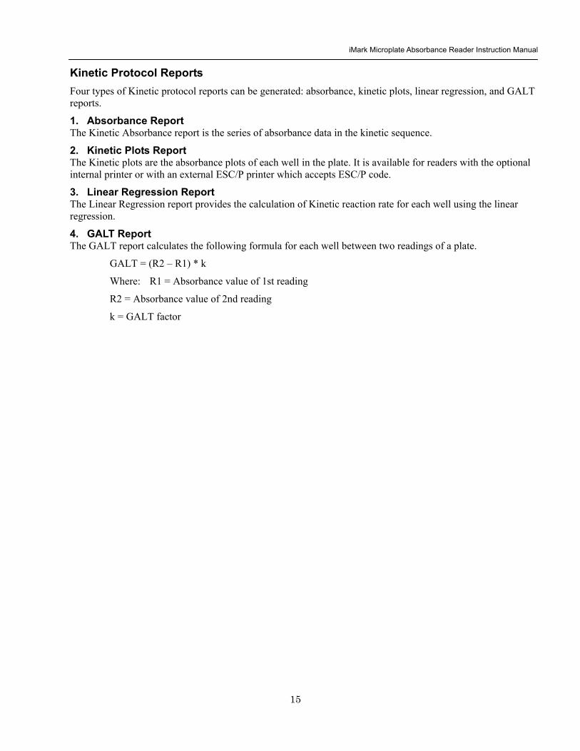
iMark Microplate Absorbance Reader Instruction Manual
16
Func key to switch from [ABC] to [abc] to [sym] key to move cursor
Func key to switch from [ABC] to [abc] to [sym] key to move cursor
Func key to switch from [ABC] to [abc] to [sym] key to move cursor
DayMonthYear HourMin
Filter wavelength setting for 1-8 positions ldquo0rdquo for no filter
Edit
Kinetic Analysis Protocol
Protocol
Security
Filters
Date Set
Lab Name
Change password
Change user
LockUnlock
Mode
Report
Calc
Mapping
Assay
Kit name
Reading Inter
Shaking Phmode
Speed
Number of reads (2-30) start delay time (0-999) Reading interval time Shake (FirstEverydisable) Speed (High Low Mid) Time Single Dual wavelength Read Speed (FastStep)
CC Limit (correlation coefficient limit) Calcrange (calculation range of reading number) for Linear regression Report
GALT factor k input (0- 9999) Result = (2nd read ndash 1st read)k for GALT Report
Manual mapping
Automatic mapping
Func key to switch [N] to [F] [N] for sample number [F] for sample type
General Kinetic or GALT assay assay type selection
Absorbance KINETIC Plots Linear regression when General Kinetic Assay selected GALT report when GALT Kinetic assay selected
For current user mode Administrator or Common user Administrator has power to switch
Special Buttons
Memory Recall
Main
Protocol Plate Data
Report Protocol
End point Kinetic
Checkmark
1-64 End point protocol storage 1-2 Kinetic protocol storage Checkmark reader test
Printout
Returns to MAIN screen
SaveSTDC
Language
BlankCNCWCPCOQCCalibratorSampleReplicate well
Save STD Curve
Rename STD Curve
Select Language
5 choices of storage number
5 choices of STD curve
Choices of pre-installed language for LCD and report printout
Bold for menu pages
LCD adj and key to change contrast
Italic for program pages
iMark Microplate Absorbance Reader Instruction Manual
17
Screen by Screen Procedures Initial Startup
01Kinetic-1 M405(1)R605(6)30read Shake999sMidEvery 382402 180901
End point mode
Kinetic mode
Self-diagnosis iMark Microplate Reader 1305 180901
System Login User Administrator Password Press ENTER
Login SCREEN
01EndPoint Assay01 M405(1)R655(6) Shake999sMid 382402 180901
Checkmark Validation Program
180901
Checkmark mode
Initializing reader
MAIN SCREEN
Self-Diagnosis This screen will appear upon power-up and during self-diagnosis Date and time are also indicated on this screen
Initialization After self-diagnosis the system initializes all the hardware
Security Check The system requires a password to confirm that the user is the authorized operator Pressing the ChangeRight arrow key will switch the user mode between Common user and Administrator Password for both Common user and Administrator is set as ldquo00000rdquo upon factory shipment Operator can change the password in the EDIT menu See Security
System Ready When this MAIN screen is on the LCD the StartStop key can be pressed for microplate reading Pressing StartStop key will begin reading with the current protocol There are three kinds of MAIN screens depending on the current protocol type Endpoint Kinetic and Checkmark program The four arrow keys Numeral keys Main key and Enter key are inactive StartStop Memory Recall Edit Print and Paper Feed keys are active
01EndPoint Assay01 M405(1)R655(6) Shake999sMid
180901
Kit name for current active protocol
01Kinetic-1 M405(1)R605(6)30read Shake999sMidEvery 382402 180901
Kinetic M Measurement wavelength and its position in the filter disk R Reference wavelength and its position in the filter disk Number of reading for KINETIC
Storage number in memory of current active protocol
Plate shaking parameters period in seconds and speed
M Measurement wavelength and its position in the filter disk R Reference wavelength and its position in the filter disk
Date (day month year)
Plate shaking parameters Period in seconds Speed (fast middle slow) Mode (before every read before first read and no shake)
End point
iMark Microplate Absorbance Reader Instruction Manual
18
Configuring the System NOTE To return to the previous screen use the backleft arrow key
Edit Menu
Security function raquoChange Password bullChange user bullLockUnlock Prtl
Change Password
LockUnlock
Change user
Change Password Current New Common user
Security for current active Protocol [Lock] Unlock
System Login User Administrator Password Press ENTER
Change Password Select ldquoChange Passwordrdquo in the Security Menu Enter the current password then move the cursor to the 3rd line and enter a new password Press Enter to complete the field entry The system will return to the previous Security Menu Change User Mode Select ldquoChange userrdquo in the Security Menu Select a desired user mode by pressing the Right Arrow key Enter the appropriate Password for the selected user mode Press Enter to complete the field entry The system will return to the previous Security Menu LockUnlock Protocol Select ldquoLockUnlock Prtlrdquo in the Security Menu Move the selected mark ldquo[ ]rdquo to the desired position Lock or Unlock using the Right Arrow key Press Enter to complete the field entry The system will return to the previous Security Menu If ldquoLockrdquo is selected the current active protocol will be protected against modification made by a Common user If ldquoUnlockrdquo is selected the current active protocol can be modified by any user mode NOTE Only the Administrator has authority to lock and unlock the Checkmark Protocol
Edit Menu This menu can be accessed by pressing the Edit key in the MAIN SCREEN
Security Menu Security Setting Select ldquoSecurityrdquo in the Edit Menu screen and press Enter The Security Menu appears on the screen
raquoProtocol Labname Security SaveSTDC Filters Language Date set LCD adj
iMark Microplate Absorbance Reader Instruction Manual
19
1400nm 5650nm 2450nm 6nm 3475nm 7nm 4650nm 8nm
Filter
DayMonthYear 16 05 01 Hour Minutes 18 55
Date set
Enter Lab name Bio Rad Laboratories uarr [ABC]
Lab name
Filter Setting Move the cursor to the desired position by using the Up Down and Right arrow keys Enter the filter wavelength on the selected position using the number keys If the selected position of the filter disk is empty enter three ldquordquo Press Enter to complete the field entry The system will return to the previous Edit Menu screen
Calendar Setting Move the cursor to the desirable position for date or time input by using the Up Down and Right arrow keys Enter the present date or time using the number keys Press Enter to complete the field entry The system will return to the previous Edit Menu screen
Lab Name Setting Use the Up and Down arrow keys to select from ldquoArdquo to ldquoZrdquo and symbols Use the Number keys for numeric input Use the Right arrow key to move the cursor to the right Use the Left arrow key to return the cursor to the Edit Menu screen Pressing the FUNCrdquo key will toggle the character mode between Upper case alphabet Lower case alphabet and symbol The current character mode is indicated on the lower right corner of the LCD
Save STD Curve gt Save STD Curve Rename STD Curve
Save STDC Save STDC Setting Select ldquoSave STDCrdquo in Edit Menu screen above and press Enter The Save STD Curve Menu appears on the screen Move the cursor to the desired position by using the Up and Down arrow keys
Select STD storage gt 1120304 1500 2 3150304 1030
Select for renaming gt 1160304 1125 2 3150304 1030
Save STD Curve To save a STD Curve select the storage number between 1 and 5 Use the Up and Down arrow keys to move the cursor to the desired storage number and press Enter to complete the selection After the storage number selection the rdquoAre you surerdquo message appears Select ldquoYesrdquo or ldquoNordquo and press Enter In case of ldquoYesrdquo the reader saves the STD Curve and returns to the Edit Menu screen If the curve fit calculation is not done or has not finished successfully an error message will appear and the STD Curve will not be saved STD curve does not
exist yet Press any key
Save STD Curve 1160304 1125 Are you sure gt Yes No
Rename STD Curve To change a name of an STD Curve select a storage number between 1 and 5 Use the Up and Down arrow keys to move the cursor to the desired storage number and press Enter to complete the selection Use the Up and Down arrow keys to select from ldquoArdquo to ldquoZrdquo and symbol Use the Number keys for numeric input Use the Right arrow key to move the cursor to the right Use the Left arrow key to return the cursor to the Edit Menu screen Pressing the FUNCrdquo key will toggle the character mode between Upper case alphabet Lower case alphabet and symbol The current character mode is indicated on the lower right corner of the LCD
1160304 1125 gtSTD Curve 1 lt
[ABC]
Save STD Curve
Rename STD Curve
iMark Microplate Absorbance Reader Instruction Manual
20
Printing Reports and Protocol information
Print menu raquoReports bullProtocol
Print Menu Print Menu Access this menu screen by pressing the Print key in the MAIN screen Printing Reports Select ldquoReportsrdquo and press Enter to print the current active plate data report Printing Protocol Information Select ldquoProtocolrdquo and press Enter to print all parameter settings in the current active protocol Stop Printing Press the StartStop key during printing to stop the print job immediately When printing is completed the system automatically returns to the MAIN screen
Select Language raquoEnglish bull bull bull
Language Changing Language Select a desired language using the Up and Down arrow keys and press Enter to complete the selection The system will generate a message for an immediate power off to restart Select ldquoYesrdquo and press Enter to activate the selected new language The newly-changed language will be applied to the LCD screen and printed reports Power off
gtgtYes No
LCD Contrast 12345678901234567890
laquo 26 raquo ENTER to complete
Adjusting LCD Contrast Adjust LCD contrast by using the Right and Left arrow keys and press Enter to complete the adjustment
LCD adj
iMark Microplate Absorbance Reader Instruction Manual
21
Memory Recall Operation
01 200500 1400 02raquo210500 1700 03 200500 1800 darr04raquo200500 1900
01raquo200500 0900 02raquo200500 1000
Memory Recall raquoProtocol bullPlate Data
Protocol type menu
Data type menu
End Point
Kinetic
End Point
Kinetic
Memory Recall Menu
Select protocol type raquoEnd Point
bullKinetic bullCheckmark
Select Protocol 02 uarrraquo Protocol -2 Protocol -3 darr Protocol -4
Select Protocol 01 raquo Kinetic -1 GALT
Select data type raquoEnd Point
bullKinetic bullCheckmark
200501 0900
Checkmark
Checkmark program has been activated Press any key
Checkmark
Selecting Protocol Move the cursor to the position of the desired protocol and press Enter to complete the selection NOTE ldquordquo indicates the currently activated protocol and ldquordquo indicates a security locked protocol There is no protocol selection with ldquoCheckmarkrdquo When a protocol is selected the system will then automatically return to the MAIN screen
Changing Current Active Protocol Select ldquoProtocolrdquo in Memory Recall menu above and press Enter The Select Protocol type menu will appear on the screen Select a protocol using the Up and Down arrow keys Press Enter to complete the selection
Selecting Plate Data Move the cursor to the position of the desired plate data and press Enter to complete the selection NOTE ldquordquo indicates the currently activated plate data There is only one storage for ldquoCheckmarkrdquo data When plate data is selected the system automatically returns to the MAIN screen
Changing Current Active Plate Data Select ldquoPlate Datardquo using the Memory Recall button and press Enter The Data type menu will appear Use the Up and Down arrow keys to select a plate data type Press Enter to complete the selection
This menu screen can be accessed by pressing the Memory Recall key in the MAIN screen
iMark Microplate Absorbance Reader Instruction Manual
22
Editing the Kinetic Protocol
Select ldquoProtocolrdquo in the Edit Menu and press Enter The Kinetic Protocol menu will appear on the screen if the current active protocol type is Kinetic
Reading speed [Fast mode] Step mode
Speed
raquoReading Speed Inter Shaking Phmode
Kinetic Mode
Kinetic Protocol Menu
raquoMode Report Calc Kit name Mapping Assay
This menu screen can be accessed by selecting ldquoModerdquo in the Kinetic Protocol menu above
Number of Reading = 20 (2-30) Start Delay time = 25 sec(0-999)
Reading
Number of Reading = 2 Start Delay time = 25 sec(0-999)
Number of Readings and Start Delay Time Setting Press the Up or Down arrow key to change the number Enter the appropriate numbers with the numeral keys and press Enter to complete the field entry The system will return to the Kinetic Edit Menu If GALT is the current assay type the number of reading fields is fixed at 2 Press the StartStop key to set the Start Delay time enter a value and press Enter until the reading starts
1-gt2raquo 100 sec 2-gt3 100 sec 3-gt4 100 sec darr4-gt5 100 sec
Inter Use same interval between all reads
raquoYes No
Setting Reading Intervals The system prompts the operator to set a reading interval before each plate run Move the cursor to the desired selection ldquoYesrdquo or ldquoNordquo and press Enter The system generates the interval entry screen Move to the active entry field by pressing the Up and Down arrow keys and enter appropriate numbers using numeral keys Press Enter to complete all field entries The system will return to the Kinetic Mode menu
Photometric Dual Measurement405 nm Reference 655 nm
Ph mode Photometric Mode Setting When the ldquoPhotometricrdquo field is activated pressing the Right arrow key will switch the field entry ldquoSinglerdquo lt-gtrdquoDualrdquo Pressing the Up or Down arrow keys will move the cursor to the next entry field Pressing the Right arrow key when the wavelength field is activated will change the wavelength to the next available selection installed in the reader Press Enter to complete all field entries
Shaking parameters Before Every read Speed Mid Time 999 sec
Shaking Plate Shake Parameters When the ldquoBeforerdquo field is activated pressing the Right arrow key will change the field entry ldquoEveryrdquo-gtrdquo--rdquo-gtrdquoFirstrdquo-gt When the ldquoSpeedrdquo field is activated pressing the Right arrow key will change the field entry ldquoMidrdquo -gtrdquoHirdquo-gtrdquoLowrdquo-gt When the ldquoTimerdquo field is activated enter the time value for plate shaking period using the numeral keys Press Enter to complete all field entries
Selecting Reading Speed Use the Up or Down arrow keys to switch the selection Press Enter to complete the selection
Edit Menu raquoProtocol Labname Security bullSaveSTDC Filters bullPrinter Date set
This menu screen can be accessed by pressing the Edit key in the MAIN screen
iMark Microplate Absorbance Reader Instruction Manual
23
Kit name for 01 raquoGAP TEST IgGlaquo uarr [ABC]
Kit name
Calculation
Mapping
Assay
Assay type selection raquo[General KINETIC] GALT assay
Calculation Param CC Limit 0910
Calcrange 10 - 20
Select Mapping mode raquoManual mapping bullAutomatic mapping
raquo[Linregression] bullAbsorbance bullKINETIC Plots
Report
Plate Mapping See Plate Map setting procedure
Result = (R2 ndash R1)k k = 999999 R11st Reading R22nd Reading
If GALT
Setting the Kit Name Use the Up and Down arrow keys to select alphabet from ldquoArdquo to ldquoZrdquo and space Use the Number keys for numeric input Use the Right arrow key to move the cursor to the right Use the Left arrow key to return to the Protocol Menu screen Pressing ldquoFUNCrdquo key will change the character mode Upper case alphabet -gt Lower case alphabet -gt symbol The current character mode is indicated on the lower right corner of the LCD
Kinetic Protocol Menu
Selecting Kinetic Assay Type Move the cursor to the desired Assay type by pressing the Up or Down arrow keys Press Enter to complete the selection The item with mark ldquo[ ]rdquo is the currently selected item GALT assay Result = factor x (2nd Read ndash 1st Read)
Selecting Report Type Move the cursor to the desired report type by pressing the Up or Down arrow keys Pressing the Right arrow key will select or deselect the item Press Enter to complete the selection Note When GALT assay is selected ldquoGALT reportrdquo shall be the only one option on this screen
raquoMode bullReport bullCalc bullKit name bullMapping bullAssay
Calculation Parameter Setting When the ldquoCC Limitrdquo field is activated pressing the numeral key will enter the desired numbers Press Enter to complete all field entries If the GALT Reports is activated pressing the numeral keys will enter the desired numbers Press Enter to complete all field entries
iMark Microplate Absorbance Reader Instruction Manual
24
Checkmark Value Setting (Administrator only)
raquoSerial Report bullLinearity ref bullMaxCV bullFilter Check ref
Checkmark Protocol Menu
raquoSerial 0000 Reptype Simple
405nm S10158 Linearity S20309 reference S31401 S42109
MaxCV raquoS115 Linearity S205 reference S302 S402
Filter max min 4051875 0329 4501167 0954 darr 4920596 0103
Serial Report
Linearity reference
Max CV
Filter check reference
Filter max min uarr 5401875 0329 6201167 0954 6900596 0103
Setting the Serial Number and Report Type Pressing the Up and Down arrow keys will move the cursor and change the field entry When ldquoSerial rdquo field is active enter the serial number that will be shown in the data sheet of the Checkmark plate using the numeral keys When the ldquoRep typerdquo field is active pressing the Right arrow key will switch the report type between ldquoSimplerdquo and ldquoFullrdquo
Setting the Linearity Reference Value Pressing the Up or Down arrow keys will move the field entry from S1 to S4 Pressing the Right arrow key will change the wavelength 405 nm-gt450 nm-gt492 nm-gt540 nm-gt620 nm-gt690 nm Use the numeral keys for the reference value setting Pressing Enter will complete all field entries at all wavelength
Max CV setting Pressing the Up or Down arrow keys will move the field entry from S1 to S4 Use the numeral keys for the Max CV setting Press Enter to complete all field entries
Setting the Filter Check Reference Value Initial screen shows the reference entries for 405 nm to 492 nm and pressing the Down arrow key at the bottom of the screen entries will scroll to the next page for 540 nm to 690 nm Pressing the Up Down and Right arrow keys will move the field entry Use the numeral keys for the filter check reference value setting Press Enter to complete all field entries
Select ldquoProtocolrdquo in the Edit Menu and press Enter The Checkmark Protocol Menu will appear on the screen if the current active protocol type is Checkmark mode
Edit Menu raquoProtocol bullLabname bullSecurity bullSaveSTDC bullFilters bullPrinter bullDate set
This menu screen can be accessed by pressing the Edit key in the MAIN screen
iMark Microplate Absorbance Reader Instruction Manual
25
Editing End Point Protocol
Upper Limit= 2000 Lower Limit= 0000 input range 0ndash3500 Upper gt Lower
Standard menu raquoSTD information
bullCurvefit bullRecall STD Curve
raquoCutoff bullMode bullReport bullMapping bullLimit bullKit name bullSTDs
Cutoff
See Plate Map setting procedure
See Standard setting procedure
See Mode setting procedure
raquo[Not use] bullRatio bullConstant bullContrl bullFormula
raquoSet photo mode bullSet shaking bullSet read mode
Select mapping mode raquoManual mapping bullAutomatic mapping
Mapping
Mode
Report
STDs
Limit
Kit name for 01 raquoGAP TEST IgGlaquo uarr [ABC]
Kit name See Kit name setting in Editing Kinetic Protocol
See Cutoff setting procedure
Select ldquoProtocolrdquo in Edit Menu screen above and press Enter The End point Protocol Menu will appear on the screen if the current active protocol type is End point mode
End Point Protocol Menu
raquo[Raw] bullMtx bullCnc bullAbs bullCut bullDif bullLim bullCrv
If ldquoDifrdquo selected
[Raw] bullMtx bullCncbullAbs bullCut [Dif] bullLim bullCrv raquorow odd-even
Seting the Report Type Use the Up and Down Arrow key to move the cursor and press the Right Arrow key to select or deselect the report type Selected report type is marked as ldquo[ ]rdquo Press Enter to complete the selection
Setting the Limit Value Use the Up and Down Arrow key to move the cursor and enter the OD value using the numeral keys The OD value range is 0000 - 3500 Press Enter to complete the selection
Edit Menu raquoProtocol bullLabname bullSecurity bullSaveSTDC bullFilters bullPrinter bullDate set
This menu screen can be accessed by pressing the Edit key in the MAIN screen
iMark Microplate Absorbance Reader Instruction Manual
26
Cutoff Setting Procedure
Cutoff Setting Menu This menu is entered by choosing Cutoff in the End Point Protocol Menu It is used to set the cutoff type The cutoff type marked with ldquo[ ]rdquo is the current selection The Up and Down arrow keys move the cursor to the desired item in the menu list When the desired parameters have been selected press Enter twice to accept the selection and to continue to the next screen Not use means that the reader does not generate the cutoff report Four types of cutoff are supported
1 Cutoff Constant 2 Cutoff Control 3 Cutoff Formula 4 Cutoff Ratio
a Cutoff Constant
Selection of SingleRanged Cutoff Constant This menu selects Single or Ranged cutoff type The cutoff type marked with ldquo[ ]rdquo is the current selection The Enter key seals the selection and resumes to the next setting screen
Single Cutoff Constant The Numerical keys and the Decimal point key are used to enter the positive and gray zone values The Right arrow key is used to select the unit The Up and Down arrow keys move the cursor to the desired parameter of the single cutoff The Enter key sets all values and selection of the cutoff constant and returns the user to the previous screen Ranged Cutoff Constant The Numerical keys and the Decimal point key are used to enter the positive and negative values The Right arrow key is used to select the unit The Up and Down arrow key moves the cursor to the desired ranged cutoff parameters The Enter key sets all values and selection of the cutoff constant and returns to the previous screen NOTE Two available Cutoff constants are ldquoAbsorbancerdquo and ldquoConcentrationrdquo If Abs is chosen the Absorbance cutoff will be done with the cutoff constant parameters defined and the absorbance report is generated For other units defined in the curve fit setting the Concentration value using the curve fit and then cutoff is done with the cutoff constant parameters defined and the concentration value of each well It is necessary to set the curve fit parameters
raquoNot usex bullRatio [Const] bullContrl bullFormula
raquoPositive gt= 9999 Gray zone 50 Unit moll
raquoPositive gt= 9999 Negative lt 1999 NegativeltPositive Unit moll
raquoRanged cutoff [Single cutoff]
Single cutoff
Ranged
iMark Microplate Absorbance Reader Instruction Manual
27
b Cutoff Control
Selection of SingleRanged Cutoff Control This menu screen selects Single or Ranged cutoff type The cutoff type marked with ldquo[ ]rdquo is the current selection The Enter key seals the selection and resumes to the next setting screen
Single Cutoff Control The Numerical keys are used to enter the gray zone value The unit is fixed to Abs The Enter key sets the value of the cutoff control and returns to the previous screen Ranged Cutoff Control There is no parameter to set for the ranged cutoff control The Enter key returns to the previous screen NOTE CNx is the mean absorbance value of Negative control wells and CPx is the mean absorbance value of Positive control wells These wells are defined in the plate map setting The cutoff is done with the Positive and Negative value to the absorbance value of each well
c Cutoff Formula
Selection of Formula This menu screen selects a formula for cutoff calculation The formula marked with ldquo[ ]rdquo is the current selection The Up and Down arrow keys move the cursor to the desired formula type The movement of the cursor follows the scroll of this screen The Enter key marks the selection and advances the user to the next setting screen The supported formula types are
1 k CNx 2 k CPx 3 k COx 4 CNx k 5 CPx k 6 COx k 7 k + CNx 8 k + CPx 9 k + COx 10 kCNx + CPx 11 ( CNx + CPx ) k 12 k1CNx + k2CPx
Coefficient for Cutoff Formula 1 to 11 The Numerical keys and the Decimal point key are used to enter the coefficient k and gray zone values The Up and Down arrow key moves the cursor to the desired parameter of the cutoff formula The Enter key sets all values of the cutoff formula and returns to the previous screen
Positive gt= CNx Gray zone 50 Unit Abs
Positive gt= CPx Negative lt CNx Unit Abs
Enter key to accept
raquoRanged cutoff [Single cutoff]
Single cutoff
Ranged
Input coefficient k = 001 (001-10) Gray zone 50(0-99)
k CNx k CPx k COx CNx k CPx k COx k k + CNx k + CPx k + COx k CNx + CPx (CNx + CPx) k
uarr raquoCNx k bullCPx k bullCOx k darr bullk + CNx
Select formula raquo[kCNx ] bullkCPx darr bullkCOx
uarr raquok + CPx bullk + COx bullkCNx + CPx darr bull(CNx + CPx) k
uarr raquok1CNx + k2CPx
Page-1
Page-2
Page-3
Page-4
iMark Microplate Absorbance Reader Instruction Manual
28
Coefficient for Cutoff Formula 12 The Numerical keys and the Decimal point key are used to enter the coefficient k1 and k2 and gray zone values The Up and Down arrow key moves the cursor to the desired cutoff formula The Enter key sets the all values of the cutoff formula and returns to the previous screen NOTE CNx is the mean absorbance value of Negative control wells CPx is the mean absorbance value of Positive control wells and COx is the mean absorbance value of Cutoff control wells These wells are defined on the plate map setting The cutoff value is calculated using the defined formula with the defined values and coefficients
d Cutoff Ratio
Ratio to Calibrator In this screen there are three items for setting the ratio to calibrator The Up and Down arrow key moves the cursor to the desired item in the menu list The Enter key seals the selection and resumes to the next setting screen
Concentration of Calibrator The Numerical keys and the Decimal point key are used to enter the calibrator concentration value The Enter key sets the value and returns to the previous screen Unit of Calibrator Seventeen standard units are supported The unit marked with ldquo[ ]rdquo is the current selection The setting procedure is the same as the unit selection of Standards Cutoff Value Setting This menu screen selects Single or Ranged cutoff type The cutoff type marked with ldquo[ ]rdquo is the current selection The Enter key marks the selection and continues to the next setting screen Single Cutoff Control The Numerical keys are used to enter the Positive cutoff concentration value and gray zone value The Enter key sets these cutoff ratio values and returns to the previous screen Ranged Cutoff Control The Numerical keys are used to input the Positive and the Negative cutoff concentration values The Enter key sets these cutoff ratios and returns to the previous screen NOTE The calibrator concentration value is used to convert the absorbance value of each well into a concentration value The ratio of ConcentrationAbsorbance of Calibrator well is applied to the conversion The cutoff uses defined Positive and Negative values to the converted concentration value of each well
Input coefficient k1 = 001 (001-10) k2 = 100 (001-10) Gray zone 50(0-99)
k1 CNx + k2 CPx
Ratio to Calibrator raquoConcentration bullUnit bullCutoff value
Concentration 9999 unit moll
uarrraquo 01 ugdl 02 ngml 03[ pgml] darr 04 pmml
raquoPositive gt= 9999 Gray zone 50
Unit moll
raquoPositive gt= 9999 Negative lt 9999 NegativeltPositive
Unit moll
raquoRanged cutoff [Single cutoff]
Concentration
Unit
Cutoff value
Single cutoff
Ranged cutoff
iMark Microplate Absorbance Reader Instruction Manual
29
Standard Setting Procedure
Standard Curve Setting Menu This menu screen is entered by choosing STDs in the End Point Protocol Menu screen It is used to set the concentration data and the curve fit type for a standard curve or to recall a memorized standard curve The Up and Down arrow key moves the cursor to the desired item in the menu list The Enter key seals the selection and continues to the next setting screen
a STD Information Setting
STD Information In this screen there are three items for setting the concentration data of standards The Up and Down arrow keys move the cursor to the desired item in the menu list The Enter key seals the selection and continues to the next setting screen
Number of Standards The Numerical keys are used to enter the number of standards ldquo0rdquo means that the curve fit report is not used The Enter key sets the number and returns to the previous screen The maximum number of standards is 12 Concentration The Numerical keys and the Decimal point key are used to enter the concentration values of standards The Up and Down arrow keys move the cursor to the desired position The movement of the cursor also follows the scroll of this screen The Enter key sets all values of the concentration of standards and returns to the previous screen Unit Seventeen units are supported The unit marked with ldquo[ ]rdquo is the current selection The Up and Down arrow keys move the cursor to the desired unit type The movement of the cursor also follows the scroll of this screen Press Enter twice to select the unit type and to return to the previous screen The supported types of unit are
1 moll 11 pgml 2 m moll 12 Uml 3 u moll 13 IUml 4 n moll 14 uIUml 5 p moll 15 mIUml 6 mgl 16 EU 7 ngl 17 Arbit 8 pgl 9 ugdl 10 ngml
STD information raquoNumber of STD bullConcentration bullUnit
STD 1 0512 STD 2 1012 STD 3 1512 darr STD 4 2053
Standard menu raquoSTD information bullCurve fit bullRecall STD curve
Concentration
Number of STD
Number of STD = 05 (0 2ndash12)
uarrraquo 01 ugdl 02 ngml 03[ pgml] darr 04 pmml
Unit
iMark Microplate Absorbance Reader Instruction Manual
30
b Curve Fit Setting
Curve Fit In this screen there are two choices to set the curve fit The Up and Down arrow keys move the cursor to the desired item in the menu list The Enter key seals the selection and resumes to the next setting screen
Curve Fit Type 10 types of curve fit are supported as below The curve fit type marked with ldquo[ ]rdquo is the current selection The Up and Down arrow key moves the cursor to the desired curve fit type The movement of the cursor follows the scroll of this screen Press Enter twice to select the unit type and to return to the previous screen The supported curve fit types are
1 5P Logistic Rodbard 2 4P Logistic Rodbard 3 5P Logistic Cook-Wilkenson 4 4P Logistic Cook-Wilkenson 5 5P Exponential 6 Sigmoid Logistic 7 Linear regression 8 Quadratic regression 9 Cubic 10 Point To Point regression
Graph Axis Four types of graph are supported The curve fit type marked with ldquo[ ]rdquo is the current selection The Up and Down arrow keys move the cursor to the desired graph type Press Enter twice to select the unit type and to return to the previous screen The supported graph types are
1 Log - Log 2 Log - Linear 3 Linear - Log 4 Linear - Linear
uarr 5p logisticRodb raquo 4p logisticRodb [5p logisticCook] darr 4p logisticCook
raquo X-Log Y-Log [X-Log Y-Lin] X-Lin Y-Log X-Lin Y-Lin
Curve fit type
Graph axis
Curve fit setting raquoCurve fit type bullGraph axis
iMark Microplate Absorbance Reader Instruction Manual
31
c Recall STD Curve Setting
Recall Setting of Standard Curve In this screen there are two items for setting the Recall STD curve as below The Up and Down arrow keys move the cursor to the desired item in the menu list
1 Recall setting (YesNo) 2 Selecting the storage number of standard curves (1 -gt 5)
Recall Setting Move the cursor to the desired position using the Up Down or Right arrow keys Enter key accepts the setting and returns the user to the standard menu screen
Yes Recalling of the standard curve is active No Recalling of the standard curve is inactive
Storage Number Selection Five memories are selectable The vacant memory (marked with asterisks on the date and time field) is also selectable It is necessary to save a standard curve before using its protocol Move the cursor to the desired position using the Up and Down keys This setting screen consists of two parts The Right arrow key is used to switch the indication field between the date and time to the standard curve name Move the cursor to the desired position using the Up and Down keys The Enter key accepts the storage number and returns to the standard menu screen NOTE If the recall of standard curve is active (the recall setting is ldquoYesrdquo) the standard information setting and the curve fit setting will be invalidated and their setting screens will not open
Recall STD curve raquoRecall setting bullSelect STD curve
Recall setting raquoYes No
Recall setting
Select STD Curve raquo1160304 1125
2 darr 3150304 1030
Select STD Curve uarrraquo4
5
Select STD Curve raquo1 STD Curve 1
2 STD Curve 2 darr 3 STD Curve 3
Select STD Curve uarrraquo4 STD Curve 4
5 STD Curve 5
Select STD curve
Right arrow key
iMark Microplate Absorbance Reader Instruction Manual
32
Mode Setting Procedure
Mode Setting Menu This menu screen is entered by choosing the Mode in the End Point Protocol Menu screen or the Kinetic Protocol Menu screen It is used to set the plate reading conditions The Up and Down arrow keys move the cursor to the desired item in the menu list The Enter key seals the selection and resumes to the next setting screen
a Set Photo Mode
Photo Mode In this screen the user chooses Single or Dual wavelength measurement and assigns the measurement and reference (for dual wavelength measurement) filters The assignment of the reference filter appears for dual wavelength measurement The Up and Down arrow keys move the cursor to the desired parameter The Right arrow key chooses SingleDual wavelength measurement and selects the installed filter on the Filters of Edit Menu screen The Enter key seals the selection and returns to the previous screen
b Set Shaking
Shaking In this screen the user selectsdeselects shaking function sets the shaking strength and enters the shaking time A shaking time of 0s indicates no shaking The maximum shaking time is 999 seconds The Up and Down arrow key moves the cursor to the desired parameters The Right arrow key toggles between YesNo (SelectDeselect) shaking or selects strength LowMiddleHigh The Numerical keys are used to enter the shaking time The Enter key seals the selection and returns the user to the previous screen
c Set Read Mode
Read Mode In this screen the user chooses Fast or Step reading and also chooses Normal or Evaluation mode The ldquo[ ]rdquoindicates the current selection The Up and Down arrow key moves the cursor to the desired parameters The Right arrow key chooses FastStep speed or chooses NormalEval mode The Enter key seals the selection and returns to the previous screen The followings are the description of each read mode parameter Reading speed
Fast reading 6 secsingle wavelength reading 10 secdual wavelength reading
Step reading 15 secsingle wavelength reading 30 secdual wavelength reading
Reading mode
Normal mode Plate reading once Evaluation mode Four plate readings per one of measurement are performed and
the average data of their plate readings is generated as a plate data
Photometric Dual Measurement400 nm Reference 655 nm
Set Shake parameters ShakeYes SpeedMid Time 199sec(0-999)
raquoReading speed [Fast ] Step bullRead mode [Normal] Eval
raquoSet Photo mode bullSet shaking bullSet read mode
Photometric Single Measurement400 nm
iMark Microplate Absorbance Reader Instruction Manual
33
Plate Map Setting Procedure
Select Mapping Mode Menu This menu screen is entered by choosing Mapping in the End Point Protocol Menu screen or the Kinetic Protocol Menu screen It is used to map the plate format The Up and Down arrow keys move the cursor next to the desired item of menu list The Enter key seals the selection and changes this screen to the next setting screen
a Manual Mapping
Manual Mapping In this screen the user can set the plate format manually Ten well types can be set Well types The supported well types are
Well type Indication on LCD
1 Blank B 2 Sample X00hellipX99 3 Standard S01hellipS99 4 In-kit Control Positive Control CP0hellipCP9 5 Weak Positive Control CW0hellipCW9 6 Negative Control CN0hellipCN9 7 Cutoff Control CO0hellipCO9 8 Calibrator CL0hellipCL9 9 QC Control QC0hellipQC9 10 Empty well -
The key assignments of well type are ldquo0EMPrdquo Empty well ldquo5QCrdquo Quality Control well ldquo1SMPrdquo Sample well ldquo6CALrdquo Calibrator well ldquo2BLKrdquo Blank well ldquo7CPrdquo Positive Control well ldquo3STDrdquo Standard well ldquo8CNrdquo Negative Control well ldquo4COrdquo Cutoff Control well ldquo9CWrdquo Weak Positive Control well
Two Edit Modes in Plate Mapping There are two editing modes for well type input mode and for well number input The current input mode is displayed at the upper left corner of the screen When using the well type input mode the mode sign is ldquo[F]rdquo When using the well number input mode the mode sign is ldquoNrdquo The cursor that encloses the editing position of well has two types of enclosures depending on the mode For example ldquo[S01]rdquo accepts the well type keys that be assigned to the numerical keys and ldquoS01rdquo accepts the numerical input The mode is easily changed with the Decimal point key Key Functions The Up Down Right and Left arrow keys move the cursor to the desired well The movement of the cursor follows the scroll of this screen The Left arrow key will return the screen to the preceding screen or the select Mapping mode Menu only if the cursor is on column 1 At this time the selection screen appears (see the left figure) The Decimal point key changes the input mode The Numerical keys have two functions one to input the number and another to select a well type The Enter key checks the consistency between the edited plate map and other parameters memorizes the plate map into the protocol and changes this screen back to the preceding screen If it finds any inconsistency a warning message will appear on the screen
Select Mapping mode raquoManual mapping bullAutomatic mapping
N 1 2 3 4 A B CN1 S01 S01 B B CN1 S02 S02 C B CN2 S03 S03 [F] 5 6 7 8 A X11 X12 X13 X14 B X21 X22 X23 X24 C X31 X32 X33[X34]
Discard change 1Yes 2No Press 1 or 2 key
iMark Microplate Absorbance Reader Instruction Manual
34
Acceptable Number Ranges for each well type 1 Blank and Empty wells do not use numbers 2 Sample and Standard wells 00 - 99 3 Standard wells 01 - 99 4 Control and Calibrator wells 0 - 9
b Automatic Mapping
Automatic Mapping The user can input the number of each well type in this screen These defined numbers are used to set a plate map automatically Well type Nine well types are available
1 BLK Blank (0-gt10) 2 CN Control CN (0-gt9) 3 CW Control CW (0-gt9) 4 CP Control CP (0-gt9) 5 CO Control CO (0-gt9) 6 QC Control QC (0-gt9) 7 CAL Calibrator (0-gt9) 8 SMP Sample (0-gt96) 9 REP Replicate well (1-gt4)
It is possible to define the number of blanks samples calibrators and controls But the number of Standards is not included because standards are defined at the Standard Setting Menu The number of replicate wells is also included It is used for replicating each well type individually Key Functions The Up Down Right and Left arrow keys are used to move the cursor to the next position The Numerical keys are used to input the mapping parameters The Enter key accepts the mapping parameters and sets a plate map automatically using these parameters During the execution of the plate mapping the Plate auto-mapping completed message appears on the screen After that the user returns automatically to the previous Protocol Menu screen If the Left arrow key is pressed at the left end position of the cursor the left figure will appear on the screen If the user chooses Yes the system will return to the previous Protocol Menu screen If the user chooses No the system will stay in this setting screen Assigning Order and Direction of plate mapping Assigning Order The order of blanks standards samples calibrators and controls are fixed as follows Numbering for standards samples calibrators and controls is started at 1
1 Blank 2 Standard 1 -gt12 ---- NOTE 3 Control CN 1-gt9 4 Control CW 1-gt9 5 Control CP 1-gt9 6 Control CO 1-gt9 7 Control QC 1-gt9 8 Calibrator 1-gt9 9 Sample 1-gt96 10 Empty well NOTE If ldquoCutoff Controlrdquo ldquoValue by Formulardquo or ldquoRatio to Calibratorrdquo is
selected for the Cutoff plate mapping skips arranging the standards Assigning Direction The placing direction of the mapping is limited to the column direction as below
Column direction A1 -gt H1 A2 -gt H2 ----- A12 -gt H12
Discard change 1Yes 2No Press 1 or 2 key
Automatic mapping BLK= 1 CP = 1 CAL= 0 CN = 1 CO = 0 SMP=93 CW = 0 QC = 0 REP= 1
Plate auto-mapping completed
iMark Microplate Absorbance Reader Instruction Manual
35
Warning and Error of Automatic Mapping Warning screen If the total number of wells mapped exceeds 96 wells a warning message in the left figure appears on the screen The calculation of the total number of mapping wells is as follows
(Blanks+Standards+CNs+CWs+CPs+COs+QCs+Calibrators+Sample)Replicates The plate mapping is executed normally and the exceeded part is invalidated Error screen If one or more mapping parameters are over the input range an error message in the left figure will appear on the screen On the third line of the LCD the name of the parameter which is out of range and its input range will appear
Example ldquoBLK 0 ndash 10rdquo In case there is more than one error the first parameter of errors is indicated By pressing any key the user returns to the automatic mapping screen Example of automatic mapping An example of automatic mapping is as below 1 Conditions of each parameter
Blank = 1 Standard = 8 Control CN = 2 CW = 0 CP = 2 CO = 0 QC = 0 Calibrator = 1 Sample = 32 Replicate number = 2
2 Plate mapping data
1 2 3 4 5 6 7 8 9 10 11 12 A B C D E F G H
B B S1 S1 S2 S2 S3 S3
S4 S4 S5 S5 S6 S6 S7 S7
S8 S8 CN1 CN1 CN2 CN2 CP1 CP1
CP2 CP2 CL1 CL1 X1 X1 X2 X2
X3 X3 X4 X4 X5 X5 X6 X6
X7 X7 X8 X8 X9 X9 X10 X10
X11 X11 X12 X12 X13 X13 X14 X14
X15 X15 X16 X16 X17 X17 X18 X18
X19 X19 X20 X20 X21 X21 X22 X22
X23 X23 X24 X24 X25 X25 X26 X26
X27 X27 X28 X28 X29 X29 X30 X30
X31 X31 X32 X32 E E E E
Warning The total Of mapped wells has Exceeded 96 Press any key
Entered value is Out of range BLK 0 ndash 10 Press any key
iMark Microplate Absorbance Reader Instruction Manual
36
Instrument Maintenance
Caution Electrical shock hazard Always disconnect the instrument from the AC power source before opening the service compartment
Caution The lamp and the lamp cover may be very hot Use caution and allow the lamp to cool
before attempting service
Installing Interference Filters 1 With the power off open the rear cover of the instrument by pressing the
release latch located on the top left portion of the cover 2 Locate the filter wheel on the left side of the instrument Note that the
filter wheel has eight filter positions 3 Rotate the filter wheel to the desired filter Grasp the top of filter frame
and pull up to remove the filter 4 Insert the new filter into the desired filter position 5 Ensure that the new filter is added to the filter list as follows Main
menu-gtEdit-gtFilters
Changing the Lamp 1 With the power off open the rear cover of the instrument by pressing the
release latch located on the top left portion of the cover 2 Remove the two screws on the black plastic cover and carefully remove
the plastic cover 3 Remove the screw on the metal cover Lift the cover up and away from
the instrument This will allow the lamp to be pulled free from the lamp housing
4 Holding the ceramic base in one hand and the lamp housing in the other carefully pull the lamp free of the base
5 Carefully insert the new lamp firmly in the ceramic base Apply even pressure when inserting the lamp so that the bulb dose not become misaligned in the reflector housing Be extremely careful not to touch the front glass of the lamp during installation
6 Position the new lamp into the housing so that the plastic guides hold the flange of the lamp
7 Carefully place the metal cover over the lamp Tighten the screw 8 Replace the plastic cover and tighten the screws 9 Close the rear cover
iMark Microplate Absorbance Reader Instruction Manual
37
Troubleshooting and Error Messages
The iMark Microplate Reader constantly monitors several functions and displays appropriate messages on the LCD as errors are encountered
Error Recommendation
LCD appears blank on power up
a Power is not turned on The AC outlet is non-functional
b Unit is not plugged into AC outlet or power code is not attached to the instrument
Check power cord connections at outlet and on the rear panel of the instrument
1
c The AC outlet is non-functional Check circuit breakers or fuses
Instrument displays ldquoLight bulb errorrdquo message indicating that the bulb is burned out
Check whether lamp is emitting light
a Lamp is not emitting light Replace the lamp as described in x
2
b Lamp is emitting light Check the alignment of the lamp in the housing Align or replace the lamp if necessary
Printer will not print on command
3
a Printer paper is not installed properly Verify that the paper is properly installed Refer to x for details
Plate carriage jams during reading and ldquoPlate carrier errorrdquo is displayed
a Plate is not seated in carriage properly Press the STOP button immediately Position the plate carefully in the carriage making certain that it is properly seated
4
b Plate height is exceeding 16mm Use Microplate which is less than 16mm in height
5 LCD displays ldquoFilter missingrdquo Install a filter in the empty position Select the installed filter by pressing Edit key
6 LCD displays ldquoFilter disk jammedrdquo indicating that the filter wheel is not turning freely
Turn off the instrument and inspect the filter wheel Turn by hand to verify that the wheel is moving freely Make sure all the filters are properly installed and firmly seated Contact your Bio-Rad representative if the filter wheel is jammed or if the problem persists
7 LCD displays ldquoFilter not installedrdquo Enter the Edit Menu by pressing Edit key and set up the filters
iMark Microplate Absorbance Reader Instruction Manual
38
Wells have color but absorbance values seem low
a Incorrect filter used for measurement andor reference wavelength
Check wavelength used in analysis Read plate in single wavelength mode at all wavelength to verify that the proper filter was used The measurement wavelength should produce the highest absorbance
b The best measurement wavelength filter for the substrate in use has not been installed in the filter wheel
Check references for the substrate you are using or determine the best measurement wavelength by analyzing the substrate product on a scanning spectrophotometer Custom filters are available from 400 to 750 nm
8
c The filters have been switched in the wheel Check that the filters are installed in the correct position
9 ldquoPrinter errorrdquo displayed Check for paper jam Install the printer paper correctly
10 ldquoBattery errorrdquo displayed The internal battery is almost dead Contact your local Bio-Rad office
11 The following messages are displayed ldquoMemory errorrdquo ldquoCalendar errorrdquo ldquoLCD hardware errorrdquo ldquoPrinter errorrdquo ldquoLight level errorrdquo ldquoDA conversion errorrdquo ldquoAD conversion errorrdquo ldquoEEPROM errorrdquo ldquoUSB errorrdquo
Contact your local Bio-Rad office if these problems persist
iMark Microplate Absorbance Reader Instruction Manual
39
Instrument Specifications Computer interface USB 20
Plate shaking 3 speeds (low mid high) Programmable time period 0 - 999 seconds
Data storage The most recent 10 data plates for end-point most recent 2 data plates of 30 readings for kinetic readings protocol data and calendarclock function shall be kept in memory by a lithium battery even when the power is off Average lifetime of the battery shall be 5 years
Warm-up time 3 minutes
Photometric Methods Single and dual wavelength
Photo detectors 8 silicon photodiodes for measurement and 1 silicon photodiode for reference
Light source Tungsten halogen lamp 20W with 3000 hours average lifetime
Spectral range 400 nm to 750 nm
Interference filters Wavelength tolerance plusmn30 nm Band width 10 nm typically
Filter capacity 8 filters
Reading speed Fast Reading 6 sec with single wavelength reading 10 sec with dual wavelength reading
Step Reading 15 sec with single wavelength reading 25 sec with dual wavelength reading
These times are minimum interval times between repetitive reads using onboard KINETIC protocol
Indication range 0000 to 35 OD
Resolution 0001 OD
Accuracy plusmn10 or 0010 from 0 to 30 OD at 490 nm
Linearity plusmn10 from 0 to 20 OD plusmn20 from 0 to 30 OD
Reproducibility 10 or 0005 OD from 0 to 20 OD 15 from 20 to 30 OD
Inter-channel variability 15 or 0005 OD from 0 to 30 OD
Stability and Drift 0010 OD at OD=1 with single wavelength reading
Built-in Printer Thermal printer Paper width 80mm
Line Voltage Universal input 100 - 240 VAC 5060Hz
Power consumption (max) 100 VA max
Dimensions (W x D x H 346 mm x 377 mm x 164 m mm
Weight 55 kg
Operating Environment 15ordmC - 40ordmC up to 90 relative humidity without condensation
Storage Temperature 10ordmC - 50ordmC up to 90 relative humidity without condensation
Life ScienceGroup
07-0816 0108 Sig 120710013301i Rev A USEG
Bio-RadLaboratories Inc
Web site wwwbio-radcom USA 800 4BIORAD Australia 61 02 9914 2800 Austria 01 877 89 01 Belgium 09 385 55 11 Brazil 55 21 3237 9400 Canada 905 364 3435 China 86 21 6426 0808 Czech Republic 420 241 430 532 Denmark 44 52 10 00 Finland 09 804 22 00 France 01 47 95 69 65Germany 089 318 84 0 Greece 30 210 777 4396 Hong Kong 852 2789 3300 Hungary 36 1 455 8800 India 91 124 4029300 Israel 03 963 6050 Italy 39 02 216091 Japan 03 6361 7000 Korea 82 2 3473 4460 Mexico 52 555 488 7670 The Netherlands 0318 540666 New Zealand 0508 805 500 Norway 23 38 41 30 Poland 48 22 331 99 99 Portugal 351 21 472 7700 Russia 7 495 721 14 04 Singapore 65 6415 3188 South Africa 27 861 246 723 Spain 34 91 590 5200 Sweden 08 555 12700 Switzerland 061 717 95 55 Taiwan 886 2 2578 7189 United Kingdom 020 8328 2000
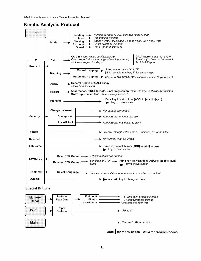
iMark Microplate Absorbance Reader Instruction Manual
17
Screen by Screen Procedures Initial Startup
01Kinetic-1 M405(1)R605(6)30read Shake999sMidEvery 382402 180901
End point mode
Kinetic mode
Self-diagnosis iMark Microplate Reader 1305 180901
System Login User Administrator Password Press ENTER
Login SCREEN
01EndPoint Assay01 M405(1)R655(6) Shake999sMid 382402 180901
Checkmark Validation Program
180901
Checkmark mode
Initializing reader
MAIN SCREEN
Self-Diagnosis This screen will appear upon power-up and during self-diagnosis Date and time are also indicated on this screen
Initialization After self-diagnosis the system initializes all the hardware
Security Check The system requires a password to confirm that the user is the authorized operator Pressing the ChangeRight arrow key will switch the user mode between Common user and Administrator Password for both Common user and Administrator is set as ldquo00000rdquo upon factory shipment Operator can change the password in the EDIT menu See Security
System Ready When this MAIN screen is on the LCD the StartStop key can be pressed for microplate reading Pressing StartStop key will begin reading with the current protocol There are three kinds of MAIN screens depending on the current protocol type Endpoint Kinetic and Checkmark program The four arrow keys Numeral keys Main key and Enter key are inactive StartStop Memory Recall Edit Print and Paper Feed keys are active
01EndPoint Assay01 M405(1)R655(6) Shake999sMid
180901
Kit name for current active protocol
01Kinetic-1 M405(1)R605(6)30read Shake999sMidEvery 382402 180901
Kinetic M Measurement wavelength and its position in the filter disk R Reference wavelength and its position in the filter disk Number of reading for KINETIC
Storage number in memory of current active protocol
Plate shaking parameters period in seconds and speed
M Measurement wavelength and its position in the filter disk R Reference wavelength and its position in the filter disk
Date (day month year)
Plate shaking parameters Period in seconds Speed (fast middle slow) Mode (before every read before first read and no shake)
End point
iMark Microplate Absorbance Reader Instruction Manual
18
Configuring the System NOTE To return to the previous screen use the backleft arrow key
Edit Menu
Security function raquoChange Password bullChange user bullLockUnlock Prtl
Change Password
LockUnlock
Change user
Change Password Current New Common user
Security for current active Protocol [Lock] Unlock
System Login User Administrator Password Press ENTER
Change Password Select ldquoChange Passwordrdquo in the Security Menu Enter the current password then move the cursor to the 3rd line and enter a new password Press Enter to complete the field entry The system will return to the previous Security Menu Change User Mode Select ldquoChange userrdquo in the Security Menu Select a desired user mode by pressing the Right Arrow key Enter the appropriate Password for the selected user mode Press Enter to complete the field entry The system will return to the previous Security Menu LockUnlock Protocol Select ldquoLockUnlock Prtlrdquo in the Security Menu Move the selected mark ldquo[ ]rdquo to the desired position Lock or Unlock using the Right Arrow key Press Enter to complete the field entry The system will return to the previous Security Menu If ldquoLockrdquo is selected the current active protocol will be protected against modification made by a Common user If ldquoUnlockrdquo is selected the current active protocol can be modified by any user mode NOTE Only the Administrator has authority to lock and unlock the Checkmark Protocol
Edit Menu This menu can be accessed by pressing the Edit key in the MAIN SCREEN
Security Menu Security Setting Select ldquoSecurityrdquo in the Edit Menu screen and press Enter The Security Menu appears on the screen
raquoProtocol Labname Security SaveSTDC Filters Language Date set LCD adj
iMark Microplate Absorbance Reader Instruction Manual
19
1400nm 5650nm 2450nm 6nm 3475nm 7nm 4650nm 8nm
Filter
DayMonthYear 16 05 01 Hour Minutes 18 55
Date set
Enter Lab name Bio Rad Laboratories uarr [ABC]
Lab name
Filter Setting Move the cursor to the desired position by using the Up Down and Right arrow keys Enter the filter wavelength on the selected position using the number keys If the selected position of the filter disk is empty enter three ldquordquo Press Enter to complete the field entry The system will return to the previous Edit Menu screen
Calendar Setting Move the cursor to the desirable position for date or time input by using the Up Down and Right arrow keys Enter the present date or time using the number keys Press Enter to complete the field entry The system will return to the previous Edit Menu screen
Lab Name Setting Use the Up and Down arrow keys to select from ldquoArdquo to ldquoZrdquo and symbols Use the Number keys for numeric input Use the Right arrow key to move the cursor to the right Use the Left arrow key to return the cursor to the Edit Menu screen Pressing the FUNCrdquo key will toggle the character mode between Upper case alphabet Lower case alphabet and symbol The current character mode is indicated on the lower right corner of the LCD
Save STD Curve gt Save STD Curve Rename STD Curve
Save STDC Save STDC Setting Select ldquoSave STDCrdquo in Edit Menu screen above and press Enter The Save STD Curve Menu appears on the screen Move the cursor to the desired position by using the Up and Down arrow keys
Select STD storage gt 1120304 1500 2 3150304 1030
Select for renaming gt 1160304 1125 2 3150304 1030
Save STD Curve To save a STD Curve select the storage number between 1 and 5 Use the Up and Down arrow keys to move the cursor to the desired storage number and press Enter to complete the selection After the storage number selection the rdquoAre you surerdquo message appears Select ldquoYesrdquo or ldquoNordquo and press Enter In case of ldquoYesrdquo the reader saves the STD Curve and returns to the Edit Menu screen If the curve fit calculation is not done or has not finished successfully an error message will appear and the STD Curve will not be saved STD curve does not
exist yet Press any key
Save STD Curve 1160304 1125 Are you sure gt Yes No
Rename STD Curve To change a name of an STD Curve select a storage number between 1 and 5 Use the Up and Down arrow keys to move the cursor to the desired storage number and press Enter to complete the selection Use the Up and Down arrow keys to select from ldquoArdquo to ldquoZrdquo and symbol Use the Number keys for numeric input Use the Right arrow key to move the cursor to the right Use the Left arrow key to return the cursor to the Edit Menu screen Pressing the FUNCrdquo key will toggle the character mode between Upper case alphabet Lower case alphabet and symbol The current character mode is indicated on the lower right corner of the LCD
1160304 1125 gtSTD Curve 1 lt
[ABC]
Save STD Curve
Rename STD Curve
iMark Microplate Absorbance Reader Instruction Manual
20
Printing Reports and Protocol information
Print menu raquoReports bullProtocol
Print Menu Print Menu Access this menu screen by pressing the Print key in the MAIN screen Printing Reports Select ldquoReportsrdquo and press Enter to print the current active plate data report Printing Protocol Information Select ldquoProtocolrdquo and press Enter to print all parameter settings in the current active protocol Stop Printing Press the StartStop key during printing to stop the print job immediately When printing is completed the system automatically returns to the MAIN screen
Select Language raquoEnglish bull bull bull
Language Changing Language Select a desired language using the Up and Down arrow keys and press Enter to complete the selection The system will generate a message for an immediate power off to restart Select ldquoYesrdquo and press Enter to activate the selected new language The newly-changed language will be applied to the LCD screen and printed reports Power off
gtgtYes No
LCD Contrast 12345678901234567890
laquo 26 raquo ENTER to complete
Adjusting LCD Contrast Adjust LCD contrast by using the Right and Left arrow keys and press Enter to complete the adjustment
LCD adj
iMark Microplate Absorbance Reader Instruction Manual
21
Memory Recall Operation
01 200500 1400 02raquo210500 1700 03 200500 1800 darr04raquo200500 1900
01raquo200500 0900 02raquo200500 1000
Memory Recall raquoProtocol bullPlate Data
Protocol type menu
Data type menu
End Point
Kinetic
End Point
Kinetic
Memory Recall Menu
Select protocol type raquoEnd Point
bullKinetic bullCheckmark
Select Protocol 02 uarrraquo Protocol -2 Protocol -3 darr Protocol -4
Select Protocol 01 raquo Kinetic -1 GALT
Select data type raquoEnd Point
bullKinetic bullCheckmark
200501 0900
Checkmark
Checkmark program has been activated Press any key
Checkmark
Selecting Protocol Move the cursor to the position of the desired protocol and press Enter to complete the selection NOTE ldquordquo indicates the currently activated protocol and ldquordquo indicates a security locked protocol There is no protocol selection with ldquoCheckmarkrdquo When a protocol is selected the system will then automatically return to the MAIN screen
Changing Current Active Protocol Select ldquoProtocolrdquo in Memory Recall menu above and press Enter The Select Protocol type menu will appear on the screen Select a protocol using the Up and Down arrow keys Press Enter to complete the selection
Selecting Plate Data Move the cursor to the position of the desired plate data and press Enter to complete the selection NOTE ldquordquo indicates the currently activated plate data There is only one storage for ldquoCheckmarkrdquo data When plate data is selected the system automatically returns to the MAIN screen
Changing Current Active Plate Data Select ldquoPlate Datardquo using the Memory Recall button and press Enter The Data type menu will appear Use the Up and Down arrow keys to select a plate data type Press Enter to complete the selection
This menu screen can be accessed by pressing the Memory Recall key in the MAIN screen
iMark Microplate Absorbance Reader Instruction Manual
22
Editing the Kinetic Protocol
Select ldquoProtocolrdquo in the Edit Menu and press Enter The Kinetic Protocol menu will appear on the screen if the current active protocol type is Kinetic
Reading speed [Fast mode] Step mode
Speed
raquoReading Speed Inter Shaking Phmode
Kinetic Mode
Kinetic Protocol Menu
raquoMode Report Calc Kit name Mapping Assay
This menu screen can be accessed by selecting ldquoModerdquo in the Kinetic Protocol menu above
Number of Reading = 20 (2-30) Start Delay time = 25 sec(0-999)
Reading
Number of Reading = 2 Start Delay time = 25 sec(0-999)
Number of Readings and Start Delay Time Setting Press the Up or Down arrow key to change the number Enter the appropriate numbers with the numeral keys and press Enter to complete the field entry The system will return to the Kinetic Edit Menu If GALT is the current assay type the number of reading fields is fixed at 2 Press the StartStop key to set the Start Delay time enter a value and press Enter until the reading starts
1-gt2raquo 100 sec 2-gt3 100 sec 3-gt4 100 sec darr4-gt5 100 sec
Inter Use same interval between all reads
raquoYes No
Setting Reading Intervals The system prompts the operator to set a reading interval before each plate run Move the cursor to the desired selection ldquoYesrdquo or ldquoNordquo and press Enter The system generates the interval entry screen Move to the active entry field by pressing the Up and Down arrow keys and enter appropriate numbers using numeral keys Press Enter to complete all field entries The system will return to the Kinetic Mode menu
Photometric Dual Measurement405 nm Reference 655 nm
Ph mode Photometric Mode Setting When the ldquoPhotometricrdquo field is activated pressing the Right arrow key will switch the field entry ldquoSinglerdquo lt-gtrdquoDualrdquo Pressing the Up or Down arrow keys will move the cursor to the next entry field Pressing the Right arrow key when the wavelength field is activated will change the wavelength to the next available selection installed in the reader Press Enter to complete all field entries
Shaking parameters Before Every read Speed Mid Time 999 sec
Shaking Plate Shake Parameters When the ldquoBeforerdquo field is activated pressing the Right arrow key will change the field entry ldquoEveryrdquo-gtrdquo--rdquo-gtrdquoFirstrdquo-gt When the ldquoSpeedrdquo field is activated pressing the Right arrow key will change the field entry ldquoMidrdquo -gtrdquoHirdquo-gtrdquoLowrdquo-gt When the ldquoTimerdquo field is activated enter the time value for plate shaking period using the numeral keys Press Enter to complete all field entries
Selecting Reading Speed Use the Up or Down arrow keys to switch the selection Press Enter to complete the selection
Edit Menu raquoProtocol Labname Security bullSaveSTDC Filters bullPrinter Date set
This menu screen can be accessed by pressing the Edit key in the MAIN screen
iMark Microplate Absorbance Reader Instruction Manual
23
Kit name for 01 raquoGAP TEST IgGlaquo uarr [ABC]
Kit name
Calculation
Mapping
Assay
Assay type selection raquo[General KINETIC] GALT assay
Calculation Param CC Limit 0910
Calcrange 10 - 20
Select Mapping mode raquoManual mapping bullAutomatic mapping
raquo[Linregression] bullAbsorbance bullKINETIC Plots
Report
Plate Mapping See Plate Map setting procedure
Result = (R2 ndash R1)k k = 999999 R11st Reading R22nd Reading
If GALT
Setting the Kit Name Use the Up and Down arrow keys to select alphabet from ldquoArdquo to ldquoZrdquo and space Use the Number keys for numeric input Use the Right arrow key to move the cursor to the right Use the Left arrow key to return to the Protocol Menu screen Pressing ldquoFUNCrdquo key will change the character mode Upper case alphabet -gt Lower case alphabet -gt symbol The current character mode is indicated on the lower right corner of the LCD
Kinetic Protocol Menu
Selecting Kinetic Assay Type Move the cursor to the desired Assay type by pressing the Up or Down arrow keys Press Enter to complete the selection The item with mark ldquo[ ]rdquo is the currently selected item GALT assay Result = factor x (2nd Read ndash 1st Read)
Selecting Report Type Move the cursor to the desired report type by pressing the Up or Down arrow keys Pressing the Right arrow key will select or deselect the item Press Enter to complete the selection Note When GALT assay is selected ldquoGALT reportrdquo shall be the only one option on this screen
raquoMode bullReport bullCalc bullKit name bullMapping bullAssay
Calculation Parameter Setting When the ldquoCC Limitrdquo field is activated pressing the numeral key will enter the desired numbers Press Enter to complete all field entries If the GALT Reports is activated pressing the numeral keys will enter the desired numbers Press Enter to complete all field entries
iMark Microplate Absorbance Reader Instruction Manual
24
Checkmark Value Setting (Administrator only)
raquoSerial Report bullLinearity ref bullMaxCV bullFilter Check ref
Checkmark Protocol Menu
raquoSerial 0000 Reptype Simple
405nm S10158 Linearity S20309 reference S31401 S42109
MaxCV raquoS115 Linearity S205 reference S302 S402
Filter max min 4051875 0329 4501167 0954 darr 4920596 0103
Serial Report
Linearity reference
Max CV
Filter check reference
Filter max min uarr 5401875 0329 6201167 0954 6900596 0103
Setting the Serial Number and Report Type Pressing the Up and Down arrow keys will move the cursor and change the field entry When ldquoSerial rdquo field is active enter the serial number that will be shown in the data sheet of the Checkmark plate using the numeral keys When the ldquoRep typerdquo field is active pressing the Right arrow key will switch the report type between ldquoSimplerdquo and ldquoFullrdquo
Setting the Linearity Reference Value Pressing the Up or Down arrow keys will move the field entry from S1 to S4 Pressing the Right arrow key will change the wavelength 405 nm-gt450 nm-gt492 nm-gt540 nm-gt620 nm-gt690 nm Use the numeral keys for the reference value setting Pressing Enter will complete all field entries at all wavelength
Max CV setting Pressing the Up or Down arrow keys will move the field entry from S1 to S4 Use the numeral keys for the Max CV setting Press Enter to complete all field entries
Setting the Filter Check Reference Value Initial screen shows the reference entries for 405 nm to 492 nm and pressing the Down arrow key at the bottom of the screen entries will scroll to the next page for 540 nm to 690 nm Pressing the Up Down and Right arrow keys will move the field entry Use the numeral keys for the filter check reference value setting Press Enter to complete all field entries
Select ldquoProtocolrdquo in the Edit Menu and press Enter The Checkmark Protocol Menu will appear on the screen if the current active protocol type is Checkmark mode
Edit Menu raquoProtocol bullLabname bullSecurity bullSaveSTDC bullFilters bullPrinter bullDate set
This menu screen can be accessed by pressing the Edit key in the MAIN screen
iMark Microplate Absorbance Reader Instruction Manual
25
Editing End Point Protocol
Upper Limit= 2000 Lower Limit= 0000 input range 0ndash3500 Upper gt Lower
Standard menu raquoSTD information
bullCurvefit bullRecall STD Curve
raquoCutoff bullMode bullReport bullMapping bullLimit bullKit name bullSTDs
Cutoff
See Plate Map setting procedure
See Standard setting procedure
See Mode setting procedure
raquo[Not use] bullRatio bullConstant bullContrl bullFormula
raquoSet photo mode bullSet shaking bullSet read mode
Select mapping mode raquoManual mapping bullAutomatic mapping
Mapping
Mode
Report
STDs
Limit
Kit name for 01 raquoGAP TEST IgGlaquo uarr [ABC]
Kit name See Kit name setting in Editing Kinetic Protocol
See Cutoff setting procedure
Select ldquoProtocolrdquo in Edit Menu screen above and press Enter The End point Protocol Menu will appear on the screen if the current active protocol type is End point mode
End Point Protocol Menu
raquo[Raw] bullMtx bullCnc bullAbs bullCut bullDif bullLim bullCrv
If ldquoDifrdquo selected
[Raw] bullMtx bullCncbullAbs bullCut [Dif] bullLim bullCrv raquorow odd-even
Seting the Report Type Use the Up and Down Arrow key to move the cursor and press the Right Arrow key to select or deselect the report type Selected report type is marked as ldquo[ ]rdquo Press Enter to complete the selection
Setting the Limit Value Use the Up and Down Arrow key to move the cursor and enter the OD value using the numeral keys The OD value range is 0000 - 3500 Press Enter to complete the selection
Edit Menu raquoProtocol bullLabname bullSecurity bullSaveSTDC bullFilters bullPrinter bullDate set
This menu screen can be accessed by pressing the Edit key in the MAIN screen
iMark Microplate Absorbance Reader Instruction Manual
26
Cutoff Setting Procedure
Cutoff Setting Menu This menu is entered by choosing Cutoff in the End Point Protocol Menu It is used to set the cutoff type The cutoff type marked with ldquo[ ]rdquo is the current selection The Up and Down arrow keys move the cursor to the desired item in the menu list When the desired parameters have been selected press Enter twice to accept the selection and to continue to the next screen Not use means that the reader does not generate the cutoff report Four types of cutoff are supported
1 Cutoff Constant 2 Cutoff Control 3 Cutoff Formula 4 Cutoff Ratio
a Cutoff Constant
Selection of SingleRanged Cutoff Constant This menu selects Single or Ranged cutoff type The cutoff type marked with ldquo[ ]rdquo is the current selection The Enter key seals the selection and resumes to the next setting screen
Single Cutoff Constant The Numerical keys and the Decimal point key are used to enter the positive and gray zone values The Right arrow key is used to select the unit The Up and Down arrow keys move the cursor to the desired parameter of the single cutoff The Enter key sets all values and selection of the cutoff constant and returns the user to the previous screen Ranged Cutoff Constant The Numerical keys and the Decimal point key are used to enter the positive and negative values The Right arrow key is used to select the unit The Up and Down arrow key moves the cursor to the desired ranged cutoff parameters The Enter key sets all values and selection of the cutoff constant and returns to the previous screen NOTE Two available Cutoff constants are ldquoAbsorbancerdquo and ldquoConcentrationrdquo If Abs is chosen the Absorbance cutoff will be done with the cutoff constant parameters defined and the absorbance report is generated For other units defined in the curve fit setting the Concentration value using the curve fit and then cutoff is done with the cutoff constant parameters defined and the concentration value of each well It is necessary to set the curve fit parameters
raquoNot usex bullRatio [Const] bullContrl bullFormula
raquoPositive gt= 9999 Gray zone 50 Unit moll
raquoPositive gt= 9999 Negative lt 1999 NegativeltPositive Unit moll
raquoRanged cutoff [Single cutoff]
Single cutoff
Ranged
iMark Microplate Absorbance Reader Instruction Manual
27
b Cutoff Control
Selection of SingleRanged Cutoff Control This menu screen selects Single or Ranged cutoff type The cutoff type marked with ldquo[ ]rdquo is the current selection The Enter key seals the selection and resumes to the next setting screen
Single Cutoff Control The Numerical keys are used to enter the gray zone value The unit is fixed to Abs The Enter key sets the value of the cutoff control and returns to the previous screen Ranged Cutoff Control There is no parameter to set for the ranged cutoff control The Enter key returns to the previous screen NOTE CNx is the mean absorbance value of Negative control wells and CPx is the mean absorbance value of Positive control wells These wells are defined in the plate map setting The cutoff is done with the Positive and Negative value to the absorbance value of each well
c Cutoff Formula
Selection of Formula This menu screen selects a formula for cutoff calculation The formula marked with ldquo[ ]rdquo is the current selection The Up and Down arrow keys move the cursor to the desired formula type The movement of the cursor follows the scroll of this screen The Enter key marks the selection and advances the user to the next setting screen The supported formula types are
1 k CNx 2 k CPx 3 k COx 4 CNx k 5 CPx k 6 COx k 7 k + CNx 8 k + CPx 9 k + COx 10 kCNx + CPx 11 ( CNx + CPx ) k 12 k1CNx + k2CPx
Coefficient for Cutoff Formula 1 to 11 The Numerical keys and the Decimal point key are used to enter the coefficient k and gray zone values The Up and Down arrow key moves the cursor to the desired parameter of the cutoff formula The Enter key sets all values of the cutoff formula and returns to the previous screen
Positive gt= CNx Gray zone 50 Unit Abs
Positive gt= CPx Negative lt CNx Unit Abs
Enter key to accept
raquoRanged cutoff [Single cutoff]
Single cutoff
Ranged
Input coefficient k = 001 (001-10) Gray zone 50(0-99)
k CNx k CPx k COx CNx k CPx k COx k k + CNx k + CPx k + COx k CNx + CPx (CNx + CPx) k
uarr raquoCNx k bullCPx k bullCOx k darr bullk + CNx
Select formula raquo[kCNx ] bullkCPx darr bullkCOx
uarr raquok + CPx bullk + COx bullkCNx + CPx darr bull(CNx + CPx) k
uarr raquok1CNx + k2CPx
Page-1
Page-2
Page-3
Page-4
iMark Microplate Absorbance Reader Instruction Manual
28
Coefficient for Cutoff Formula 12 The Numerical keys and the Decimal point key are used to enter the coefficient k1 and k2 and gray zone values The Up and Down arrow key moves the cursor to the desired cutoff formula The Enter key sets the all values of the cutoff formula and returns to the previous screen NOTE CNx is the mean absorbance value of Negative control wells CPx is the mean absorbance value of Positive control wells and COx is the mean absorbance value of Cutoff control wells These wells are defined on the plate map setting The cutoff value is calculated using the defined formula with the defined values and coefficients
d Cutoff Ratio
Ratio to Calibrator In this screen there are three items for setting the ratio to calibrator The Up and Down arrow key moves the cursor to the desired item in the menu list The Enter key seals the selection and resumes to the next setting screen
Concentration of Calibrator The Numerical keys and the Decimal point key are used to enter the calibrator concentration value The Enter key sets the value and returns to the previous screen Unit of Calibrator Seventeen standard units are supported The unit marked with ldquo[ ]rdquo is the current selection The setting procedure is the same as the unit selection of Standards Cutoff Value Setting This menu screen selects Single or Ranged cutoff type The cutoff type marked with ldquo[ ]rdquo is the current selection The Enter key marks the selection and continues to the next setting screen Single Cutoff Control The Numerical keys are used to enter the Positive cutoff concentration value and gray zone value The Enter key sets these cutoff ratio values and returns to the previous screen Ranged Cutoff Control The Numerical keys are used to input the Positive and the Negative cutoff concentration values The Enter key sets these cutoff ratios and returns to the previous screen NOTE The calibrator concentration value is used to convert the absorbance value of each well into a concentration value The ratio of ConcentrationAbsorbance of Calibrator well is applied to the conversion The cutoff uses defined Positive and Negative values to the converted concentration value of each well
Input coefficient k1 = 001 (001-10) k2 = 100 (001-10) Gray zone 50(0-99)
k1 CNx + k2 CPx
Ratio to Calibrator raquoConcentration bullUnit bullCutoff value
Concentration 9999 unit moll
uarrraquo 01 ugdl 02 ngml 03[ pgml] darr 04 pmml
raquoPositive gt= 9999 Gray zone 50
Unit moll
raquoPositive gt= 9999 Negative lt 9999 NegativeltPositive
Unit moll
raquoRanged cutoff [Single cutoff]
Concentration
Unit
Cutoff value
Single cutoff
Ranged cutoff
iMark Microplate Absorbance Reader Instruction Manual
29
Standard Setting Procedure
Standard Curve Setting Menu This menu screen is entered by choosing STDs in the End Point Protocol Menu screen It is used to set the concentration data and the curve fit type for a standard curve or to recall a memorized standard curve The Up and Down arrow key moves the cursor to the desired item in the menu list The Enter key seals the selection and continues to the next setting screen
a STD Information Setting
STD Information In this screen there are three items for setting the concentration data of standards The Up and Down arrow keys move the cursor to the desired item in the menu list The Enter key seals the selection and continues to the next setting screen
Number of Standards The Numerical keys are used to enter the number of standards ldquo0rdquo means that the curve fit report is not used The Enter key sets the number and returns to the previous screen The maximum number of standards is 12 Concentration The Numerical keys and the Decimal point key are used to enter the concentration values of standards The Up and Down arrow keys move the cursor to the desired position The movement of the cursor also follows the scroll of this screen The Enter key sets all values of the concentration of standards and returns to the previous screen Unit Seventeen units are supported The unit marked with ldquo[ ]rdquo is the current selection The Up and Down arrow keys move the cursor to the desired unit type The movement of the cursor also follows the scroll of this screen Press Enter twice to select the unit type and to return to the previous screen The supported types of unit are
1 moll 11 pgml 2 m moll 12 Uml 3 u moll 13 IUml 4 n moll 14 uIUml 5 p moll 15 mIUml 6 mgl 16 EU 7 ngl 17 Arbit 8 pgl 9 ugdl 10 ngml
STD information raquoNumber of STD bullConcentration bullUnit
STD 1 0512 STD 2 1012 STD 3 1512 darr STD 4 2053
Standard menu raquoSTD information bullCurve fit bullRecall STD curve
Concentration
Number of STD
Number of STD = 05 (0 2ndash12)
uarrraquo 01 ugdl 02 ngml 03[ pgml] darr 04 pmml
Unit
iMark Microplate Absorbance Reader Instruction Manual
30
b Curve Fit Setting
Curve Fit In this screen there are two choices to set the curve fit The Up and Down arrow keys move the cursor to the desired item in the menu list The Enter key seals the selection and resumes to the next setting screen
Curve Fit Type 10 types of curve fit are supported as below The curve fit type marked with ldquo[ ]rdquo is the current selection The Up and Down arrow key moves the cursor to the desired curve fit type The movement of the cursor follows the scroll of this screen Press Enter twice to select the unit type and to return to the previous screen The supported curve fit types are
1 5P Logistic Rodbard 2 4P Logistic Rodbard 3 5P Logistic Cook-Wilkenson 4 4P Logistic Cook-Wilkenson 5 5P Exponential 6 Sigmoid Logistic 7 Linear regression 8 Quadratic regression 9 Cubic 10 Point To Point regression
Graph Axis Four types of graph are supported The curve fit type marked with ldquo[ ]rdquo is the current selection The Up and Down arrow keys move the cursor to the desired graph type Press Enter twice to select the unit type and to return to the previous screen The supported graph types are
1 Log - Log 2 Log - Linear 3 Linear - Log 4 Linear - Linear
uarr 5p logisticRodb raquo 4p logisticRodb [5p logisticCook] darr 4p logisticCook
raquo X-Log Y-Log [X-Log Y-Lin] X-Lin Y-Log X-Lin Y-Lin
Curve fit type
Graph axis
Curve fit setting raquoCurve fit type bullGraph axis
iMark Microplate Absorbance Reader Instruction Manual
31
c Recall STD Curve Setting
Recall Setting of Standard Curve In this screen there are two items for setting the Recall STD curve as below The Up and Down arrow keys move the cursor to the desired item in the menu list
1 Recall setting (YesNo) 2 Selecting the storage number of standard curves (1 -gt 5)
Recall Setting Move the cursor to the desired position using the Up Down or Right arrow keys Enter key accepts the setting and returns the user to the standard menu screen
Yes Recalling of the standard curve is active No Recalling of the standard curve is inactive
Storage Number Selection Five memories are selectable The vacant memory (marked with asterisks on the date and time field) is also selectable It is necessary to save a standard curve before using its protocol Move the cursor to the desired position using the Up and Down keys This setting screen consists of two parts The Right arrow key is used to switch the indication field between the date and time to the standard curve name Move the cursor to the desired position using the Up and Down keys The Enter key accepts the storage number and returns to the standard menu screen NOTE If the recall of standard curve is active (the recall setting is ldquoYesrdquo) the standard information setting and the curve fit setting will be invalidated and their setting screens will not open
Recall STD curve raquoRecall setting bullSelect STD curve
Recall setting raquoYes No
Recall setting
Select STD Curve raquo1160304 1125
2 darr 3150304 1030
Select STD Curve uarrraquo4
5
Select STD Curve raquo1 STD Curve 1
2 STD Curve 2 darr 3 STD Curve 3
Select STD Curve uarrraquo4 STD Curve 4
5 STD Curve 5
Select STD curve
Right arrow key
iMark Microplate Absorbance Reader Instruction Manual
32
Mode Setting Procedure
Mode Setting Menu This menu screen is entered by choosing the Mode in the End Point Protocol Menu screen or the Kinetic Protocol Menu screen It is used to set the plate reading conditions The Up and Down arrow keys move the cursor to the desired item in the menu list The Enter key seals the selection and resumes to the next setting screen
a Set Photo Mode
Photo Mode In this screen the user chooses Single or Dual wavelength measurement and assigns the measurement and reference (for dual wavelength measurement) filters The assignment of the reference filter appears for dual wavelength measurement The Up and Down arrow keys move the cursor to the desired parameter The Right arrow key chooses SingleDual wavelength measurement and selects the installed filter on the Filters of Edit Menu screen The Enter key seals the selection and returns to the previous screen
b Set Shaking
Shaking In this screen the user selectsdeselects shaking function sets the shaking strength and enters the shaking time A shaking time of 0s indicates no shaking The maximum shaking time is 999 seconds The Up and Down arrow key moves the cursor to the desired parameters The Right arrow key toggles between YesNo (SelectDeselect) shaking or selects strength LowMiddleHigh The Numerical keys are used to enter the shaking time The Enter key seals the selection and returns the user to the previous screen
c Set Read Mode
Read Mode In this screen the user chooses Fast or Step reading and also chooses Normal or Evaluation mode The ldquo[ ]rdquoindicates the current selection The Up and Down arrow key moves the cursor to the desired parameters The Right arrow key chooses FastStep speed or chooses NormalEval mode The Enter key seals the selection and returns to the previous screen The followings are the description of each read mode parameter Reading speed
Fast reading 6 secsingle wavelength reading 10 secdual wavelength reading
Step reading 15 secsingle wavelength reading 30 secdual wavelength reading
Reading mode
Normal mode Plate reading once Evaluation mode Four plate readings per one of measurement are performed and
the average data of their plate readings is generated as a plate data
Photometric Dual Measurement400 nm Reference 655 nm
Set Shake parameters ShakeYes SpeedMid Time 199sec(0-999)
raquoReading speed [Fast ] Step bullRead mode [Normal] Eval
raquoSet Photo mode bullSet shaking bullSet read mode
Photometric Single Measurement400 nm
iMark Microplate Absorbance Reader Instruction Manual
33
Plate Map Setting Procedure
Select Mapping Mode Menu This menu screen is entered by choosing Mapping in the End Point Protocol Menu screen or the Kinetic Protocol Menu screen It is used to map the plate format The Up and Down arrow keys move the cursor next to the desired item of menu list The Enter key seals the selection and changes this screen to the next setting screen
a Manual Mapping
Manual Mapping In this screen the user can set the plate format manually Ten well types can be set Well types The supported well types are
Well type Indication on LCD
1 Blank B 2 Sample X00hellipX99 3 Standard S01hellipS99 4 In-kit Control Positive Control CP0hellipCP9 5 Weak Positive Control CW0hellipCW9 6 Negative Control CN0hellipCN9 7 Cutoff Control CO0hellipCO9 8 Calibrator CL0hellipCL9 9 QC Control QC0hellipQC9 10 Empty well -
The key assignments of well type are ldquo0EMPrdquo Empty well ldquo5QCrdquo Quality Control well ldquo1SMPrdquo Sample well ldquo6CALrdquo Calibrator well ldquo2BLKrdquo Blank well ldquo7CPrdquo Positive Control well ldquo3STDrdquo Standard well ldquo8CNrdquo Negative Control well ldquo4COrdquo Cutoff Control well ldquo9CWrdquo Weak Positive Control well
Two Edit Modes in Plate Mapping There are two editing modes for well type input mode and for well number input The current input mode is displayed at the upper left corner of the screen When using the well type input mode the mode sign is ldquo[F]rdquo When using the well number input mode the mode sign is ldquoNrdquo The cursor that encloses the editing position of well has two types of enclosures depending on the mode For example ldquo[S01]rdquo accepts the well type keys that be assigned to the numerical keys and ldquoS01rdquo accepts the numerical input The mode is easily changed with the Decimal point key Key Functions The Up Down Right and Left arrow keys move the cursor to the desired well The movement of the cursor follows the scroll of this screen The Left arrow key will return the screen to the preceding screen or the select Mapping mode Menu only if the cursor is on column 1 At this time the selection screen appears (see the left figure) The Decimal point key changes the input mode The Numerical keys have two functions one to input the number and another to select a well type The Enter key checks the consistency between the edited plate map and other parameters memorizes the plate map into the protocol and changes this screen back to the preceding screen If it finds any inconsistency a warning message will appear on the screen
Select Mapping mode raquoManual mapping bullAutomatic mapping
N 1 2 3 4 A B CN1 S01 S01 B B CN1 S02 S02 C B CN2 S03 S03 [F] 5 6 7 8 A X11 X12 X13 X14 B X21 X22 X23 X24 C X31 X32 X33[X34]
Discard change 1Yes 2No Press 1 or 2 key
iMark Microplate Absorbance Reader Instruction Manual
34
Acceptable Number Ranges for each well type 1 Blank and Empty wells do not use numbers 2 Sample and Standard wells 00 - 99 3 Standard wells 01 - 99 4 Control and Calibrator wells 0 - 9
b Automatic Mapping
Automatic Mapping The user can input the number of each well type in this screen These defined numbers are used to set a plate map automatically Well type Nine well types are available
1 BLK Blank (0-gt10) 2 CN Control CN (0-gt9) 3 CW Control CW (0-gt9) 4 CP Control CP (0-gt9) 5 CO Control CO (0-gt9) 6 QC Control QC (0-gt9) 7 CAL Calibrator (0-gt9) 8 SMP Sample (0-gt96) 9 REP Replicate well (1-gt4)
It is possible to define the number of blanks samples calibrators and controls But the number of Standards is not included because standards are defined at the Standard Setting Menu The number of replicate wells is also included It is used for replicating each well type individually Key Functions The Up Down Right and Left arrow keys are used to move the cursor to the next position The Numerical keys are used to input the mapping parameters The Enter key accepts the mapping parameters and sets a plate map automatically using these parameters During the execution of the plate mapping the Plate auto-mapping completed message appears on the screen After that the user returns automatically to the previous Protocol Menu screen If the Left arrow key is pressed at the left end position of the cursor the left figure will appear on the screen If the user chooses Yes the system will return to the previous Protocol Menu screen If the user chooses No the system will stay in this setting screen Assigning Order and Direction of plate mapping Assigning Order The order of blanks standards samples calibrators and controls are fixed as follows Numbering for standards samples calibrators and controls is started at 1
1 Blank 2 Standard 1 -gt12 ---- NOTE 3 Control CN 1-gt9 4 Control CW 1-gt9 5 Control CP 1-gt9 6 Control CO 1-gt9 7 Control QC 1-gt9 8 Calibrator 1-gt9 9 Sample 1-gt96 10 Empty well NOTE If ldquoCutoff Controlrdquo ldquoValue by Formulardquo or ldquoRatio to Calibratorrdquo is
selected for the Cutoff plate mapping skips arranging the standards Assigning Direction The placing direction of the mapping is limited to the column direction as below
Column direction A1 -gt H1 A2 -gt H2 ----- A12 -gt H12
Discard change 1Yes 2No Press 1 or 2 key
Automatic mapping BLK= 1 CP = 1 CAL= 0 CN = 1 CO = 0 SMP=93 CW = 0 QC = 0 REP= 1
Plate auto-mapping completed
iMark Microplate Absorbance Reader Instruction Manual
35
Warning and Error of Automatic Mapping Warning screen If the total number of wells mapped exceeds 96 wells a warning message in the left figure appears on the screen The calculation of the total number of mapping wells is as follows
(Blanks+Standards+CNs+CWs+CPs+COs+QCs+Calibrators+Sample)Replicates The plate mapping is executed normally and the exceeded part is invalidated Error screen If one or more mapping parameters are over the input range an error message in the left figure will appear on the screen On the third line of the LCD the name of the parameter which is out of range and its input range will appear
Example ldquoBLK 0 ndash 10rdquo In case there is more than one error the first parameter of errors is indicated By pressing any key the user returns to the automatic mapping screen Example of automatic mapping An example of automatic mapping is as below 1 Conditions of each parameter
Blank = 1 Standard = 8 Control CN = 2 CW = 0 CP = 2 CO = 0 QC = 0 Calibrator = 1 Sample = 32 Replicate number = 2
2 Plate mapping data
1 2 3 4 5 6 7 8 9 10 11 12 A B C D E F G H
B B S1 S1 S2 S2 S3 S3
S4 S4 S5 S5 S6 S6 S7 S7
S8 S8 CN1 CN1 CN2 CN2 CP1 CP1
CP2 CP2 CL1 CL1 X1 X1 X2 X2
X3 X3 X4 X4 X5 X5 X6 X6
X7 X7 X8 X8 X9 X9 X10 X10
X11 X11 X12 X12 X13 X13 X14 X14
X15 X15 X16 X16 X17 X17 X18 X18
X19 X19 X20 X20 X21 X21 X22 X22
X23 X23 X24 X24 X25 X25 X26 X26
X27 X27 X28 X28 X29 X29 X30 X30
X31 X31 X32 X32 E E E E
Warning The total Of mapped wells has Exceeded 96 Press any key
Entered value is Out of range BLK 0 ndash 10 Press any key
iMark Microplate Absorbance Reader Instruction Manual
36
Instrument Maintenance
Caution Electrical shock hazard Always disconnect the instrument from the AC power source before opening the service compartment
Caution The lamp and the lamp cover may be very hot Use caution and allow the lamp to cool
before attempting service
Installing Interference Filters 1 With the power off open the rear cover of the instrument by pressing the
release latch located on the top left portion of the cover 2 Locate the filter wheel on the left side of the instrument Note that the
filter wheel has eight filter positions 3 Rotate the filter wheel to the desired filter Grasp the top of filter frame
and pull up to remove the filter 4 Insert the new filter into the desired filter position 5 Ensure that the new filter is added to the filter list as follows Main
menu-gtEdit-gtFilters
Changing the Lamp 1 With the power off open the rear cover of the instrument by pressing the
release latch located on the top left portion of the cover 2 Remove the two screws on the black plastic cover and carefully remove
the plastic cover 3 Remove the screw on the metal cover Lift the cover up and away from
the instrument This will allow the lamp to be pulled free from the lamp housing
4 Holding the ceramic base in one hand and the lamp housing in the other carefully pull the lamp free of the base
5 Carefully insert the new lamp firmly in the ceramic base Apply even pressure when inserting the lamp so that the bulb dose not become misaligned in the reflector housing Be extremely careful not to touch the front glass of the lamp during installation
6 Position the new lamp into the housing so that the plastic guides hold the flange of the lamp
7 Carefully place the metal cover over the lamp Tighten the screw 8 Replace the plastic cover and tighten the screws 9 Close the rear cover
iMark Microplate Absorbance Reader Instruction Manual
37
Troubleshooting and Error Messages
The iMark Microplate Reader constantly monitors several functions and displays appropriate messages on the LCD as errors are encountered
Error Recommendation
LCD appears blank on power up
a Power is not turned on The AC outlet is non-functional
b Unit is not plugged into AC outlet or power code is not attached to the instrument
Check power cord connections at outlet and on the rear panel of the instrument
1
c The AC outlet is non-functional Check circuit breakers or fuses
Instrument displays ldquoLight bulb errorrdquo message indicating that the bulb is burned out
Check whether lamp is emitting light
a Lamp is not emitting light Replace the lamp as described in x
2
b Lamp is emitting light Check the alignment of the lamp in the housing Align or replace the lamp if necessary
Printer will not print on command
3
a Printer paper is not installed properly Verify that the paper is properly installed Refer to x for details
Plate carriage jams during reading and ldquoPlate carrier errorrdquo is displayed
a Plate is not seated in carriage properly Press the STOP button immediately Position the plate carefully in the carriage making certain that it is properly seated
4
b Plate height is exceeding 16mm Use Microplate which is less than 16mm in height
5 LCD displays ldquoFilter missingrdquo Install a filter in the empty position Select the installed filter by pressing Edit key
6 LCD displays ldquoFilter disk jammedrdquo indicating that the filter wheel is not turning freely
Turn off the instrument and inspect the filter wheel Turn by hand to verify that the wheel is moving freely Make sure all the filters are properly installed and firmly seated Contact your Bio-Rad representative if the filter wheel is jammed or if the problem persists
7 LCD displays ldquoFilter not installedrdquo Enter the Edit Menu by pressing Edit key and set up the filters
iMark Microplate Absorbance Reader Instruction Manual
38
Wells have color but absorbance values seem low
a Incorrect filter used for measurement andor reference wavelength
Check wavelength used in analysis Read plate in single wavelength mode at all wavelength to verify that the proper filter was used The measurement wavelength should produce the highest absorbance
b The best measurement wavelength filter for the substrate in use has not been installed in the filter wheel
Check references for the substrate you are using or determine the best measurement wavelength by analyzing the substrate product on a scanning spectrophotometer Custom filters are available from 400 to 750 nm
8
c The filters have been switched in the wheel Check that the filters are installed in the correct position
9 ldquoPrinter errorrdquo displayed Check for paper jam Install the printer paper correctly
10 ldquoBattery errorrdquo displayed The internal battery is almost dead Contact your local Bio-Rad office
11 The following messages are displayed ldquoMemory errorrdquo ldquoCalendar errorrdquo ldquoLCD hardware errorrdquo ldquoPrinter errorrdquo ldquoLight level errorrdquo ldquoDA conversion errorrdquo ldquoAD conversion errorrdquo ldquoEEPROM errorrdquo ldquoUSB errorrdquo
Contact your local Bio-Rad office if these problems persist
iMark Microplate Absorbance Reader Instruction Manual
39
Instrument Specifications Computer interface USB 20
Plate shaking 3 speeds (low mid high) Programmable time period 0 - 999 seconds
Data storage The most recent 10 data plates for end-point most recent 2 data plates of 30 readings for kinetic readings protocol data and calendarclock function shall be kept in memory by a lithium battery even when the power is off Average lifetime of the battery shall be 5 years
Warm-up time 3 minutes
Photometric Methods Single and dual wavelength
Photo detectors 8 silicon photodiodes for measurement and 1 silicon photodiode for reference
Light source Tungsten halogen lamp 20W with 3000 hours average lifetime
Spectral range 400 nm to 750 nm
Interference filters Wavelength tolerance plusmn30 nm Band width 10 nm typically
Filter capacity 8 filters
Reading speed Fast Reading 6 sec with single wavelength reading 10 sec with dual wavelength reading
Step Reading 15 sec with single wavelength reading 25 sec with dual wavelength reading
These times are minimum interval times between repetitive reads using onboard KINETIC protocol
Indication range 0000 to 35 OD
Resolution 0001 OD
Accuracy plusmn10 or 0010 from 0 to 30 OD at 490 nm
Linearity plusmn10 from 0 to 20 OD plusmn20 from 0 to 30 OD
Reproducibility 10 or 0005 OD from 0 to 20 OD 15 from 20 to 30 OD
Inter-channel variability 15 or 0005 OD from 0 to 30 OD
Stability and Drift 0010 OD at OD=1 with single wavelength reading
Built-in Printer Thermal printer Paper width 80mm
Line Voltage Universal input 100 - 240 VAC 5060Hz
Power consumption (max) 100 VA max
Dimensions (W x D x H 346 mm x 377 mm x 164 m mm
Weight 55 kg
Operating Environment 15ordmC - 40ordmC up to 90 relative humidity without condensation
Storage Temperature 10ordmC - 50ordmC up to 90 relative humidity without condensation
Life ScienceGroup
07-0816 0108 Sig 120710013301i Rev A USEG
Bio-RadLaboratories Inc
Web site wwwbio-radcom USA 800 4BIORAD Australia 61 02 9914 2800 Austria 01 877 89 01 Belgium 09 385 55 11 Brazil 55 21 3237 9400 Canada 905 364 3435 China 86 21 6426 0808 Czech Republic 420 241 430 532 Denmark 44 52 10 00 Finland 09 804 22 00 France 01 47 95 69 65Germany 089 318 84 0 Greece 30 210 777 4396 Hong Kong 852 2789 3300 Hungary 36 1 455 8800 India 91 124 4029300 Israel 03 963 6050 Italy 39 02 216091 Japan 03 6361 7000 Korea 82 2 3473 4460 Mexico 52 555 488 7670 The Netherlands 0318 540666 New Zealand 0508 805 500 Norway 23 38 41 30 Poland 48 22 331 99 99 Portugal 351 21 472 7700 Russia 7 495 721 14 04 Singapore 65 6415 3188 South Africa 27 861 246 723 Spain 34 91 590 5200 Sweden 08 555 12700 Switzerland 061 717 95 55 Taiwan 886 2 2578 7189 United Kingdom 020 8328 2000
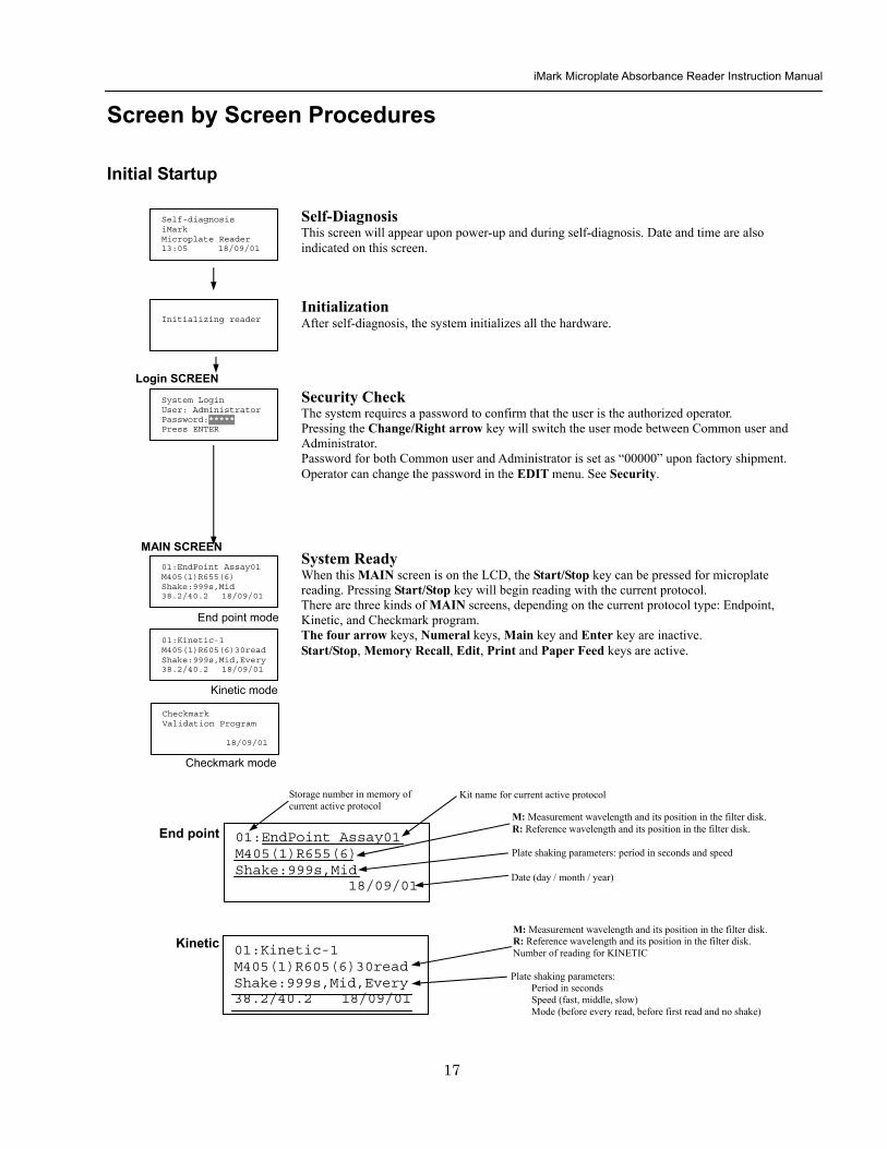
iMark Microplate Absorbance Reader Instruction Manual
18
Configuring the System NOTE To return to the previous screen use the backleft arrow key
Edit Menu
Security function raquoChange Password bullChange user bullLockUnlock Prtl
Change Password
LockUnlock
Change user
Change Password Current New Common user
Security for current active Protocol [Lock] Unlock
System Login User Administrator Password Press ENTER
Change Password Select ldquoChange Passwordrdquo in the Security Menu Enter the current password then move the cursor to the 3rd line and enter a new password Press Enter to complete the field entry The system will return to the previous Security Menu Change User Mode Select ldquoChange userrdquo in the Security Menu Select a desired user mode by pressing the Right Arrow key Enter the appropriate Password for the selected user mode Press Enter to complete the field entry The system will return to the previous Security Menu LockUnlock Protocol Select ldquoLockUnlock Prtlrdquo in the Security Menu Move the selected mark ldquo[ ]rdquo to the desired position Lock or Unlock using the Right Arrow key Press Enter to complete the field entry The system will return to the previous Security Menu If ldquoLockrdquo is selected the current active protocol will be protected against modification made by a Common user If ldquoUnlockrdquo is selected the current active protocol can be modified by any user mode NOTE Only the Administrator has authority to lock and unlock the Checkmark Protocol
Edit Menu This menu can be accessed by pressing the Edit key in the MAIN SCREEN
Security Menu Security Setting Select ldquoSecurityrdquo in the Edit Menu screen and press Enter The Security Menu appears on the screen
raquoProtocol Labname Security SaveSTDC Filters Language Date set LCD adj
iMark Microplate Absorbance Reader Instruction Manual
19
1400nm 5650nm 2450nm 6nm 3475nm 7nm 4650nm 8nm
Filter
DayMonthYear 16 05 01 Hour Minutes 18 55
Date set
Enter Lab name Bio Rad Laboratories uarr [ABC]
Lab name
Filter Setting Move the cursor to the desired position by using the Up Down and Right arrow keys Enter the filter wavelength on the selected position using the number keys If the selected position of the filter disk is empty enter three ldquordquo Press Enter to complete the field entry The system will return to the previous Edit Menu screen
Calendar Setting Move the cursor to the desirable position for date or time input by using the Up Down and Right arrow keys Enter the present date or time using the number keys Press Enter to complete the field entry The system will return to the previous Edit Menu screen
Lab Name Setting Use the Up and Down arrow keys to select from ldquoArdquo to ldquoZrdquo and symbols Use the Number keys for numeric input Use the Right arrow key to move the cursor to the right Use the Left arrow key to return the cursor to the Edit Menu screen Pressing the FUNCrdquo key will toggle the character mode between Upper case alphabet Lower case alphabet and symbol The current character mode is indicated on the lower right corner of the LCD
Save STD Curve gt Save STD Curve Rename STD Curve
Save STDC Save STDC Setting Select ldquoSave STDCrdquo in Edit Menu screen above and press Enter The Save STD Curve Menu appears on the screen Move the cursor to the desired position by using the Up and Down arrow keys
Select STD storage gt 1120304 1500 2 3150304 1030
Select for renaming gt 1160304 1125 2 3150304 1030
Save STD Curve To save a STD Curve select the storage number between 1 and 5 Use the Up and Down arrow keys to move the cursor to the desired storage number and press Enter to complete the selection After the storage number selection the rdquoAre you surerdquo message appears Select ldquoYesrdquo or ldquoNordquo and press Enter In case of ldquoYesrdquo the reader saves the STD Curve and returns to the Edit Menu screen If the curve fit calculation is not done or has not finished successfully an error message will appear and the STD Curve will not be saved STD curve does not
exist yet Press any key
Save STD Curve 1160304 1125 Are you sure gt Yes No
Rename STD Curve To change a name of an STD Curve select a storage number between 1 and 5 Use the Up and Down arrow keys to move the cursor to the desired storage number and press Enter to complete the selection Use the Up and Down arrow keys to select from ldquoArdquo to ldquoZrdquo and symbol Use the Number keys for numeric input Use the Right arrow key to move the cursor to the right Use the Left arrow key to return the cursor to the Edit Menu screen Pressing the FUNCrdquo key will toggle the character mode between Upper case alphabet Lower case alphabet and symbol The current character mode is indicated on the lower right corner of the LCD
1160304 1125 gtSTD Curve 1 lt
[ABC]
Save STD Curve
Rename STD Curve
iMark Microplate Absorbance Reader Instruction Manual
20
Printing Reports and Protocol information
Print menu raquoReports bullProtocol
Print Menu Print Menu Access this menu screen by pressing the Print key in the MAIN screen Printing Reports Select ldquoReportsrdquo and press Enter to print the current active plate data report Printing Protocol Information Select ldquoProtocolrdquo and press Enter to print all parameter settings in the current active protocol Stop Printing Press the StartStop key during printing to stop the print job immediately When printing is completed the system automatically returns to the MAIN screen
Select Language raquoEnglish bull bull bull
Language Changing Language Select a desired language using the Up and Down arrow keys and press Enter to complete the selection The system will generate a message for an immediate power off to restart Select ldquoYesrdquo and press Enter to activate the selected new language The newly-changed language will be applied to the LCD screen and printed reports Power off
gtgtYes No
LCD Contrast 12345678901234567890
laquo 26 raquo ENTER to complete
Adjusting LCD Contrast Adjust LCD contrast by using the Right and Left arrow keys and press Enter to complete the adjustment
LCD adj
iMark Microplate Absorbance Reader Instruction Manual
21
Memory Recall Operation
01 200500 1400 02raquo210500 1700 03 200500 1800 darr04raquo200500 1900
01raquo200500 0900 02raquo200500 1000
Memory Recall raquoProtocol bullPlate Data
Protocol type menu
Data type menu
End Point
Kinetic
End Point
Kinetic
Memory Recall Menu
Select protocol type raquoEnd Point
bullKinetic bullCheckmark
Select Protocol 02 uarrraquo Protocol -2 Protocol -3 darr Protocol -4
Select Protocol 01 raquo Kinetic -1 GALT
Select data type raquoEnd Point
bullKinetic bullCheckmark
200501 0900
Checkmark
Checkmark program has been activated Press any key
Checkmark
Selecting Protocol Move the cursor to the position of the desired protocol and press Enter to complete the selection NOTE ldquordquo indicates the currently activated protocol and ldquordquo indicates a security locked protocol There is no protocol selection with ldquoCheckmarkrdquo When a protocol is selected the system will then automatically return to the MAIN screen
Changing Current Active Protocol Select ldquoProtocolrdquo in Memory Recall menu above and press Enter The Select Protocol type menu will appear on the screen Select a protocol using the Up and Down arrow keys Press Enter to complete the selection
Selecting Plate Data Move the cursor to the position of the desired plate data and press Enter to complete the selection NOTE ldquordquo indicates the currently activated plate data There is only one storage for ldquoCheckmarkrdquo data When plate data is selected the system automatically returns to the MAIN screen
Changing Current Active Plate Data Select ldquoPlate Datardquo using the Memory Recall button and press Enter The Data type menu will appear Use the Up and Down arrow keys to select a plate data type Press Enter to complete the selection
This menu screen can be accessed by pressing the Memory Recall key in the MAIN screen
iMark Microplate Absorbance Reader Instruction Manual
22
Editing the Kinetic Protocol
Select ldquoProtocolrdquo in the Edit Menu and press Enter The Kinetic Protocol menu will appear on the screen if the current active protocol type is Kinetic
Reading speed [Fast mode] Step mode
Speed
raquoReading Speed Inter Shaking Phmode
Kinetic Mode
Kinetic Protocol Menu
raquoMode Report Calc Kit name Mapping Assay
This menu screen can be accessed by selecting ldquoModerdquo in the Kinetic Protocol menu above
Number of Reading = 20 (2-30) Start Delay time = 25 sec(0-999)
Reading
Number of Reading = 2 Start Delay time = 25 sec(0-999)
Number of Readings and Start Delay Time Setting Press the Up or Down arrow key to change the number Enter the appropriate numbers with the numeral keys and press Enter to complete the field entry The system will return to the Kinetic Edit Menu If GALT is the current assay type the number of reading fields is fixed at 2 Press the StartStop key to set the Start Delay time enter a value and press Enter until the reading starts
1-gt2raquo 100 sec 2-gt3 100 sec 3-gt4 100 sec darr4-gt5 100 sec
Inter Use same interval between all reads
raquoYes No
Setting Reading Intervals The system prompts the operator to set a reading interval before each plate run Move the cursor to the desired selection ldquoYesrdquo or ldquoNordquo and press Enter The system generates the interval entry screen Move to the active entry field by pressing the Up and Down arrow keys and enter appropriate numbers using numeral keys Press Enter to complete all field entries The system will return to the Kinetic Mode menu
Photometric Dual Measurement405 nm Reference 655 nm
Ph mode Photometric Mode Setting When the ldquoPhotometricrdquo field is activated pressing the Right arrow key will switch the field entry ldquoSinglerdquo lt-gtrdquoDualrdquo Pressing the Up or Down arrow keys will move the cursor to the next entry field Pressing the Right arrow key when the wavelength field is activated will change the wavelength to the next available selection installed in the reader Press Enter to complete all field entries
Shaking parameters Before Every read Speed Mid Time 999 sec
Shaking Plate Shake Parameters When the ldquoBeforerdquo field is activated pressing the Right arrow key will change the field entry ldquoEveryrdquo-gtrdquo--rdquo-gtrdquoFirstrdquo-gt When the ldquoSpeedrdquo field is activated pressing the Right arrow key will change the field entry ldquoMidrdquo -gtrdquoHirdquo-gtrdquoLowrdquo-gt When the ldquoTimerdquo field is activated enter the time value for plate shaking period using the numeral keys Press Enter to complete all field entries
Selecting Reading Speed Use the Up or Down arrow keys to switch the selection Press Enter to complete the selection
Edit Menu raquoProtocol Labname Security bullSaveSTDC Filters bullPrinter Date set
This menu screen can be accessed by pressing the Edit key in the MAIN screen
iMark Microplate Absorbance Reader Instruction Manual
23
Kit name for 01 raquoGAP TEST IgGlaquo uarr [ABC]
Kit name
Calculation
Mapping
Assay
Assay type selection raquo[General KINETIC] GALT assay
Calculation Param CC Limit 0910
Calcrange 10 - 20
Select Mapping mode raquoManual mapping bullAutomatic mapping
raquo[Linregression] bullAbsorbance bullKINETIC Plots
Report
Plate Mapping See Plate Map setting procedure
Result = (R2 ndash R1)k k = 999999 R11st Reading R22nd Reading
If GALT
Setting the Kit Name Use the Up and Down arrow keys to select alphabet from ldquoArdquo to ldquoZrdquo and space Use the Number keys for numeric input Use the Right arrow key to move the cursor to the right Use the Left arrow key to return to the Protocol Menu screen Pressing ldquoFUNCrdquo key will change the character mode Upper case alphabet -gt Lower case alphabet -gt symbol The current character mode is indicated on the lower right corner of the LCD
Kinetic Protocol Menu
Selecting Kinetic Assay Type Move the cursor to the desired Assay type by pressing the Up or Down arrow keys Press Enter to complete the selection The item with mark ldquo[ ]rdquo is the currently selected item GALT assay Result = factor x (2nd Read ndash 1st Read)
Selecting Report Type Move the cursor to the desired report type by pressing the Up or Down arrow keys Pressing the Right arrow key will select or deselect the item Press Enter to complete the selection Note When GALT assay is selected ldquoGALT reportrdquo shall be the only one option on this screen
raquoMode bullReport bullCalc bullKit name bullMapping bullAssay
Calculation Parameter Setting When the ldquoCC Limitrdquo field is activated pressing the numeral key will enter the desired numbers Press Enter to complete all field entries If the GALT Reports is activated pressing the numeral keys will enter the desired numbers Press Enter to complete all field entries
iMark Microplate Absorbance Reader Instruction Manual
24
Checkmark Value Setting (Administrator only)
raquoSerial Report bullLinearity ref bullMaxCV bullFilter Check ref
Checkmark Protocol Menu
raquoSerial 0000 Reptype Simple
405nm S10158 Linearity S20309 reference S31401 S42109
MaxCV raquoS115 Linearity S205 reference S302 S402
Filter max min 4051875 0329 4501167 0954 darr 4920596 0103
Serial Report
Linearity reference
Max CV
Filter check reference
Filter max min uarr 5401875 0329 6201167 0954 6900596 0103
Setting the Serial Number and Report Type Pressing the Up and Down arrow keys will move the cursor and change the field entry When ldquoSerial rdquo field is active enter the serial number that will be shown in the data sheet of the Checkmark plate using the numeral keys When the ldquoRep typerdquo field is active pressing the Right arrow key will switch the report type between ldquoSimplerdquo and ldquoFullrdquo
Setting the Linearity Reference Value Pressing the Up or Down arrow keys will move the field entry from S1 to S4 Pressing the Right arrow key will change the wavelength 405 nm-gt450 nm-gt492 nm-gt540 nm-gt620 nm-gt690 nm Use the numeral keys for the reference value setting Pressing Enter will complete all field entries at all wavelength
Max CV setting Pressing the Up or Down arrow keys will move the field entry from S1 to S4 Use the numeral keys for the Max CV setting Press Enter to complete all field entries
Setting the Filter Check Reference Value Initial screen shows the reference entries for 405 nm to 492 nm and pressing the Down arrow key at the bottom of the screen entries will scroll to the next page for 540 nm to 690 nm Pressing the Up Down and Right arrow keys will move the field entry Use the numeral keys for the filter check reference value setting Press Enter to complete all field entries
Select ldquoProtocolrdquo in the Edit Menu and press Enter The Checkmark Protocol Menu will appear on the screen if the current active protocol type is Checkmark mode
Edit Menu raquoProtocol bullLabname bullSecurity bullSaveSTDC bullFilters bullPrinter bullDate set
This menu screen can be accessed by pressing the Edit key in the MAIN screen
iMark Microplate Absorbance Reader Instruction Manual
25
Editing End Point Protocol
Upper Limit= 2000 Lower Limit= 0000 input range 0ndash3500 Upper gt Lower
Standard menu raquoSTD information
bullCurvefit bullRecall STD Curve
raquoCutoff bullMode bullReport bullMapping bullLimit bullKit name bullSTDs
Cutoff
See Plate Map setting procedure
See Standard setting procedure
See Mode setting procedure
raquo[Not use] bullRatio bullConstant bullContrl bullFormula
raquoSet photo mode bullSet shaking bullSet read mode
Select mapping mode raquoManual mapping bullAutomatic mapping
Mapping
Mode
Report
STDs
Limit
Kit name for 01 raquoGAP TEST IgGlaquo uarr [ABC]
Kit name See Kit name setting in Editing Kinetic Protocol
See Cutoff setting procedure
Select ldquoProtocolrdquo in Edit Menu screen above and press Enter The End point Protocol Menu will appear on the screen if the current active protocol type is End point mode
End Point Protocol Menu
raquo[Raw] bullMtx bullCnc bullAbs bullCut bullDif bullLim bullCrv
If ldquoDifrdquo selected
[Raw] bullMtx bullCncbullAbs bullCut [Dif] bullLim bullCrv raquorow odd-even
Seting the Report Type Use the Up and Down Arrow key to move the cursor and press the Right Arrow key to select or deselect the report type Selected report type is marked as ldquo[ ]rdquo Press Enter to complete the selection
Setting the Limit Value Use the Up and Down Arrow key to move the cursor and enter the OD value using the numeral keys The OD value range is 0000 - 3500 Press Enter to complete the selection
Edit Menu raquoProtocol bullLabname bullSecurity bullSaveSTDC bullFilters bullPrinter bullDate set
This menu screen can be accessed by pressing the Edit key in the MAIN screen
iMark Microplate Absorbance Reader Instruction Manual
26
Cutoff Setting Procedure
Cutoff Setting Menu This menu is entered by choosing Cutoff in the End Point Protocol Menu It is used to set the cutoff type The cutoff type marked with ldquo[ ]rdquo is the current selection The Up and Down arrow keys move the cursor to the desired item in the menu list When the desired parameters have been selected press Enter twice to accept the selection and to continue to the next screen Not use means that the reader does not generate the cutoff report Four types of cutoff are supported
1 Cutoff Constant 2 Cutoff Control 3 Cutoff Formula 4 Cutoff Ratio
a Cutoff Constant
Selection of SingleRanged Cutoff Constant This menu selects Single or Ranged cutoff type The cutoff type marked with ldquo[ ]rdquo is the current selection The Enter key seals the selection and resumes to the next setting screen
Single Cutoff Constant The Numerical keys and the Decimal point key are used to enter the positive and gray zone values The Right arrow key is used to select the unit The Up and Down arrow keys move the cursor to the desired parameter of the single cutoff The Enter key sets all values and selection of the cutoff constant and returns the user to the previous screen Ranged Cutoff Constant The Numerical keys and the Decimal point key are used to enter the positive and negative values The Right arrow key is used to select the unit The Up and Down arrow key moves the cursor to the desired ranged cutoff parameters The Enter key sets all values and selection of the cutoff constant and returns to the previous screen NOTE Two available Cutoff constants are ldquoAbsorbancerdquo and ldquoConcentrationrdquo If Abs is chosen the Absorbance cutoff will be done with the cutoff constant parameters defined and the absorbance report is generated For other units defined in the curve fit setting the Concentration value using the curve fit and then cutoff is done with the cutoff constant parameters defined and the concentration value of each well It is necessary to set the curve fit parameters
raquoNot usex bullRatio [Const] bullContrl bullFormula
raquoPositive gt= 9999 Gray zone 50 Unit moll
raquoPositive gt= 9999 Negative lt 1999 NegativeltPositive Unit moll
raquoRanged cutoff [Single cutoff]
Single cutoff
Ranged
iMark Microplate Absorbance Reader Instruction Manual
27
b Cutoff Control
Selection of SingleRanged Cutoff Control This menu screen selects Single or Ranged cutoff type The cutoff type marked with ldquo[ ]rdquo is the current selection The Enter key seals the selection and resumes to the next setting screen
Single Cutoff Control The Numerical keys are used to enter the gray zone value The unit is fixed to Abs The Enter key sets the value of the cutoff control and returns to the previous screen Ranged Cutoff Control There is no parameter to set for the ranged cutoff control The Enter key returns to the previous screen NOTE CNx is the mean absorbance value of Negative control wells and CPx is the mean absorbance value of Positive control wells These wells are defined in the plate map setting The cutoff is done with the Positive and Negative value to the absorbance value of each well
c Cutoff Formula
Selection of Formula This menu screen selects a formula for cutoff calculation The formula marked with ldquo[ ]rdquo is the current selection The Up and Down arrow keys move the cursor to the desired formula type The movement of the cursor follows the scroll of this screen The Enter key marks the selection and advances the user to the next setting screen The supported formula types are
1 k CNx 2 k CPx 3 k COx 4 CNx k 5 CPx k 6 COx k 7 k + CNx 8 k + CPx 9 k + COx 10 kCNx + CPx 11 ( CNx + CPx ) k 12 k1CNx + k2CPx
Coefficient for Cutoff Formula 1 to 11 The Numerical keys and the Decimal point key are used to enter the coefficient k and gray zone values The Up and Down arrow key moves the cursor to the desired parameter of the cutoff formula The Enter key sets all values of the cutoff formula and returns to the previous screen
Positive gt= CNx Gray zone 50 Unit Abs
Positive gt= CPx Negative lt CNx Unit Abs
Enter key to accept
raquoRanged cutoff [Single cutoff]
Single cutoff
Ranged
Input coefficient k = 001 (001-10) Gray zone 50(0-99)
k CNx k CPx k COx CNx k CPx k COx k k + CNx k + CPx k + COx k CNx + CPx (CNx + CPx) k
uarr raquoCNx k bullCPx k bullCOx k darr bullk + CNx
Select formula raquo[kCNx ] bullkCPx darr bullkCOx
uarr raquok + CPx bullk + COx bullkCNx + CPx darr bull(CNx + CPx) k
uarr raquok1CNx + k2CPx
Page-1
Page-2
Page-3
Page-4
iMark Microplate Absorbance Reader Instruction Manual
28
Coefficient for Cutoff Formula 12 The Numerical keys and the Decimal point key are used to enter the coefficient k1 and k2 and gray zone values The Up and Down arrow key moves the cursor to the desired cutoff formula The Enter key sets the all values of the cutoff formula and returns to the previous screen NOTE CNx is the mean absorbance value of Negative control wells CPx is the mean absorbance value of Positive control wells and COx is the mean absorbance value of Cutoff control wells These wells are defined on the plate map setting The cutoff value is calculated using the defined formula with the defined values and coefficients
d Cutoff Ratio
Ratio to Calibrator In this screen there are three items for setting the ratio to calibrator The Up and Down arrow key moves the cursor to the desired item in the menu list The Enter key seals the selection and resumes to the next setting screen
Concentration of Calibrator The Numerical keys and the Decimal point key are used to enter the calibrator concentration value The Enter key sets the value and returns to the previous screen Unit of Calibrator Seventeen standard units are supported The unit marked with ldquo[ ]rdquo is the current selection The setting procedure is the same as the unit selection of Standards Cutoff Value Setting This menu screen selects Single or Ranged cutoff type The cutoff type marked with ldquo[ ]rdquo is the current selection The Enter key marks the selection and continues to the next setting screen Single Cutoff Control The Numerical keys are used to enter the Positive cutoff concentration value and gray zone value The Enter key sets these cutoff ratio values and returns to the previous screen Ranged Cutoff Control The Numerical keys are used to input the Positive and the Negative cutoff concentration values The Enter key sets these cutoff ratios and returns to the previous screen NOTE The calibrator concentration value is used to convert the absorbance value of each well into a concentration value The ratio of ConcentrationAbsorbance of Calibrator well is applied to the conversion The cutoff uses defined Positive and Negative values to the converted concentration value of each well
Input coefficient k1 = 001 (001-10) k2 = 100 (001-10) Gray zone 50(0-99)
k1 CNx + k2 CPx
Ratio to Calibrator raquoConcentration bullUnit bullCutoff value
Concentration 9999 unit moll
uarrraquo 01 ugdl 02 ngml 03[ pgml] darr 04 pmml
raquoPositive gt= 9999 Gray zone 50
Unit moll
raquoPositive gt= 9999 Negative lt 9999 NegativeltPositive
Unit moll
raquoRanged cutoff [Single cutoff]
Concentration
Unit
Cutoff value
Single cutoff
Ranged cutoff
iMark Microplate Absorbance Reader Instruction Manual
29
Standard Setting Procedure
Standard Curve Setting Menu This menu screen is entered by choosing STDs in the End Point Protocol Menu screen It is used to set the concentration data and the curve fit type for a standard curve or to recall a memorized standard curve The Up and Down arrow key moves the cursor to the desired item in the menu list The Enter key seals the selection and continues to the next setting screen
a STD Information Setting
STD Information In this screen there are three items for setting the concentration data of standards The Up and Down arrow keys move the cursor to the desired item in the menu list The Enter key seals the selection and continues to the next setting screen
Number of Standards The Numerical keys are used to enter the number of standards ldquo0rdquo means that the curve fit report is not used The Enter key sets the number and returns to the previous screen The maximum number of standards is 12 Concentration The Numerical keys and the Decimal point key are used to enter the concentration values of standards The Up and Down arrow keys move the cursor to the desired position The movement of the cursor also follows the scroll of this screen The Enter key sets all values of the concentration of standards and returns to the previous screen Unit Seventeen units are supported The unit marked with ldquo[ ]rdquo is the current selection The Up and Down arrow keys move the cursor to the desired unit type The movement of the cursor also follows the scroll of this screen Press Enter twice to select the unit type and to return to the previous screen The supported types of unit are
1 moll 11 pgml 2 m moll 12 Uml 3 u moll 13 IUml 4 n moll 14 uIUml 5 p moll 15 mIUml 6 mgl 16 EU 7 ngl 17 Arbit 8 pgl 9 ugdl 10 ngml
STD information raquoNumber of STD bullConcentration bullUnit
STD 1 0512 STD 2 1012 STD 3 1512 darr STD 4 2053
Standard menu raquoSTD information bullCurve fit bullRecall STD curve
Concentration
Number of STD
Number of STD = 05 (0 2ndash12)
uarrraquo 01 ugdl 02 ngml 03[ pgml] darr 04 pmml
Unit
iMark Microplate Absorbance Reader Instruction Manual
30
b Curve Fit Setting
Curve Fit In this screen there are two choices to set the curve fit The Up and Down arrow keys move the cursor to the desired item in the menu list The Enter key seals the selection and resumes to the next setting screen
Curve Fit Type 10 types of curve fit are supported as below The curve fit type marked with ldquo[ ]rdquo is the current selection The Up and Down arrow key moves the cursor to the desired curve fit type The movement of the cursor follows the scroll of this screen Press Enter twice to select the unit type and to return to the previous screen The supported curve fit types are
1 5P Logistic Rodbard 2 4P Logistic Rodbard 3 5P Logistic Cook-Wilkenson 4 4P Logistic Cook-Wilkenson 5 5P Exponential 6 Sigmoid Logistic 7 Linear regression 8 Quadratic regression 9 Cubic 10 Point To Point regression
Graph Axis Four types of graph are supported The curve fit type marked with ldquo[ ]rdquo is the current selection The Up and Down arrow keys move the cursor to the desired graph type Press Enter twice to select the unit type and to return to the previous screen The supported graph types are
1 Log - Log 2 Log - Linear 3 Linear - Log 4 Linear - Linear
uarr 5p logisticRodb raquo 4p logisticRodb [5p logisticCook] darr 4p logisticCook
raquo X-Log Y-Log [X-Log Y-Lin] X-Lin Y-Log X-Lin Y-Lin
Curve fit type
Graph axis
Curve fit setting raquoCurve fit type bullGraph axis
iMark Microplate Absorbance Reader Instruction Manual
31
c Recall STD Curve Setting
Recall Setting of Standard Curve In this screen there are two items for setting the Recall STD curve as below The Up and Down arrow keys move the cursor to the desired item in the menu list
1 Recall setting (YesNo) 2 Selecting the storage number of standard curves (1 -gt 5)
Recall Setting Move the cursor to the desired position using the Up Down or Right arrow keys Enter key accepts the setting and returns the user to the standard menu screen
Yes Recalling of the standard curve is active No Recalling of the standard curve is inactive
Storage Number Selection Five memories are selectable The vacant memory (marked with asterisks on the date and time field) is also selectable It is necessary to save a standard curve before using its protocol Move the cursor to the desired position using the Up and Down keys This setting screen consists of two parts The Right arrow key is used to switch the indication field between the date and time to the standard curve name Move the cursor to the desired position using the Up and Down keys The Enter key accepts the storage number and returns to the standard menu screen NOTE If the recall of standard curve is active (the recall setting is ldquoYesrdquo) the standard information setting and the curve fit setting will be invalidated and their setting screens will not open
Recall STD curve raquoRecall setting bullSelect STD curve
Recall setting raquoYes No
Recall setting
Select STD Curve raquo1160304 1125
2 darr 3150304 1030
Select STD Curve uarrraquo4
5
Select STD Curve raquo1 STD Curve 1
2 STD Curve 2 darr 3 STD Curve 3
Select STD Curve uarrraquo4 STD Curve 4
5 STD Curve 5
Select STD curve
Right arrow key
iMark Microplate Absorbance Reader Instruction Manual
32
Mode Setting Procedure
Mode Setting Menu This menu screen is entered by choosing the Mode in the End Point Protocol Menu screen or the Kinetic Protocol Menu screen It is used to set the plate reading conditions The Up and Down arrow keys move the cursor to the desired item in the menu list The Enter key seals the selection and resumes to the next setting screen
a Set Photo Mode
Photo Mode In this screen the user chooses Single or Dual wavelength measurement and assigns the measurement and reference (for dual wavelength measurement) filters The assignment of the reference filter appears for dual wavelength measurement The Up and Down arrow keys move the cursor to the desired parameter The Right arrow key chooses SingleDual wavelength measurement and selects the installed filter on the Filters of Edit Menu screen The Enter key seals the selection and returns to the previous screen
b Set Shaking
Shaking In this screen the user selectsdeselects shaking function sets the shaking strength and enters the shaking time A shaking time of 0s indicates no shaking The maximum shaking time is 999 seconds The Up and Down arrow key moves the cursor to the desired parameters The Right arrow key toggles between YesNo (SelectDeselect) shaking or selects strength LowMiddleHigh The Numerical keys are used to enter the shaking time The Enter key seals the selection and returns the user to the previous screen
c Set Read Mode
Read Mode In this screen the user chooses Fast or Step reading and also chooses Normal or Evaluation mode The ldquo[ ]rdquoindicates the current selection The Up and Down arrow key moves the cursor to the desired parameters The Right arrow key chooses FastStep speed or chooses NormalEval mode The Enter key seals the selection and returns to the previous screen The followings are the description of each read mode parameter Reading speed
Fast reading 6 secsingle wavelength reading 10 secdual wavelength reading
Step reading 15 secsingle wavelength reading 30 secdual wavelength reading
Reading mode
Normal mode Plate reading once Evaluation mode Four plate readings per one of measurement are performed and
the average data of their plate readings is generated as a plate data
Photometric Dual Measurement400 nm Reference 655 nm
Set Shake parameters ShakeYes SpeedMid Time 199sec(0-999)
raquoReading speed [Fast ] Step bullRead mode [Normal] Eval
raquoSet Photo mode bullSet shaking bullSet read mode
Photometric Single Measurement400 nm
iMark Microplate Absorbance Reader Instruction Manual
33
Plate Map Setting Procedure
Select Mapping Mode Menu This menu screen is entered by choosing Mapping in the End Point Protocol Menu screen or the Kinetic Protocol Menu screen It is used to map the plate format The Up and Down arrow keys move the cursor next to the desired item of menu list The Enter key seals the selection and changes this screen to the next setting screen
a Manual Mapping
Manual Mapping In this screen the user can set the plate format manually Ten well types can be set Well types The supported well types are
Well type Indication on LCD
1 Blank B 2 Sample X00hellipX99 3 Standard S01hellipS99 4 In-kit Control Positive Control CP0hellipCP9 5 Weak Positive Control CW0hellipCW9 6 Negative Control CN0hellipCN9 7 Cutoff Control CO0hellipCO9 8 Calibrator CL0hellipCL9 9 QC Control QC0hellipQC9 10 Empty well -
The key assignments of well type are ldquo0EMPrdquo Empty well ldquo5QCrdquo Quality Control well ldquo1SMPrdquo Sample well ldquo6CALrdquo Calibrator well ldquo2BLKrdquo Blank well ldquo7CPrdquo Positive Control well ldquo3STDrdquo Standard well ldquo8CNrdquo Negative Control well ldquo4COrdquo Cutoff Control well ldquo9CWrdquo Weak Positive Control well
Two Edit Modes in Plate Mapping There are two editing modes for well type input mode and for well number input The current input mode is displayed at the upper left corner of the screen When using the well type input mode the mode sign is ldquo[F]rdquo When using the well number input mode the mode sign is ldquoNrdquo The cursor that encloses the editing position of well has two types of enclosures depending on the mode For example ldquo[S01]rdquo accepts the well type keys that be assigned to the numerical keys and ldquoS01rdquo accepts the numerical input The mode is easily changed with the Decimal point key Key Functions The Up Down Right and Left arrow keys move the cursor to the desired well The movement of the cursor follows the scroll of this screen The Left arrow key will return the screen to the preceding screen or the select Mapping mode Menu only if the cursor is on column 1 At this time the selection screen appears (see the left figure) The Decimal point key changes the input mode The Numerical keys have two functions one to input the number and another to select a well type The Enter key checks the consistency between the edited plate map and other parameters memorizes the plate map into the protocol and changes this screen back to the preceding screen If it finds any inconsistency a warning message will appear on the screen
Select Mapping mode raquoManual mapping bullAutomatic mapping
N 1 2 3 4 A B CN1 S01 S01 B B CN1 S02 S02 C B CN2 S03 S03 [F] 5 6 7 8 A X11 X12 X13 X14 B X21 X22 X23 X24 C X31 X32 X33[X34]
Discard change 1Yes 2No Press 1 or 2 key
iMark Microplate Absorbance Reader Instruction Manual
34
Acceptable Number Ranges for each well type 1 Blank and Empty wells do not use numbers 2 Sample and Standard wells 00 - 99 3 Standard wells 01 - 99 4 Control and Calibrator wells 0 - 9
b Automatic Mapping
Automatic Mapping The user can input the number of each well type in this screen These defined numbers are used to set a plate map automatically Well type Nine well types are available
1 BLK Blank (0-gt10) 2 CN Control CN (0-gt9) 3 CW Control CW (0-gt9) 4 CP Control CP (0-gt9) 5 CO Control CO (0-gt9) 6 QC Control QC (0-gt9) 7 CAL Calibrator (0-gt9) 8 SMP Sample (0-gt96) 9 REP Replicate well (1-gt4)
It is possible to define the number of blanks samples calibrators and controls But the number of Standards is not included because standards are defined at the Standard Setting Menu The number of replicate wells is also included It is used for replicating each well type individually Key Functions The Up Down Right and Left arrow keys are used to move the cursor to the next position The Numerical keys are used to input the mapping parameters The Enter key accepts the mapping parameters and sets a plate map automatically using these parameters During the execution of the plate mapping the Plate auto-mapping completed message appears on the screen After that the user returns automatically to the previous Protocol Menu screen If the Left arrow key is pressed at the left end position of the cursor the left figure will appear on the screen If the user chooses Yes the system will return to the previous Protocol Menu screen If the user chooses No the system will stay in this setting screen Assigning Order and Direction of plate mapping Assigning Order The order of blanks standards samples calibrators and controls are fixed as follows Numbering for standards samples calibrators and controls is started at 1
1 Blank 2 Standard 1 -gt12 ---- NOTE 3 Control CN 1-gt9 4 Control CW 1-gt9 5 Control CP 1-gt9 6 Control CO 1-gt9 7 Control QC 1-gt9 8 Calibrator 1-gt9 9 Sample 1-gt96 10 Empty well NOTE If ldquoCutoff Controlrdquo ldquoValue by Formulardquo or ldquoRatio to Calibratorrdquo is
selected for the Cutoff plate mapping skips arranging the standards Assigning Direction The placing direction of the mapping is limited to the column direction as below
Column direction A1 -gt H1 A2 -gt H2 ----- A12 -gt H12
Discard change 1Yes 2No Press 1 or 2 key
Automatic mapping BLK= 1 CP = 1 CAL= 0 CN = 1 CO = 0 SMP=93 CW = 0 QC = 0 REP= 1
Plate auto-mapping completed
iMark Microplate Absorbance Reader Instruction Manual
35
Warning and Error of Automatic Mapping Warning screen If the total number of wells mapped exceeds 96 wells a warning message in the left figure appears on the screen The calculation of the total number of mapping wells is as follows
(Blanks+Standards+CNs+CWs+CPs+COs+QCs+Calibrators+Sample)Replicates The plate mapping is executed normally and the exceeded part is invalidated Error screen If one or more mapping parameters are over the input range an error message in the left figure will appear on the screen On the third line of the LCD the name of the parameter which is out of range and its input range will appear
Example ldquoBLK 0 ndash 10rdquo In case there is more than one error the first parameter of errors is indicated By pressing any key the user returns to the automatic mapping screen Example of automatic mapping An example of automatic mapping is as below 1 Conditions of each parameter
Blank = 1 Standard = 8 Control CN = 2 CW = 0 CP = 2 CO = 0 QC = 0 Calibrator = 1 Sample = 32 Replicate number = 2
2 Plate mapping data
1 2 3 4 5 6 7 8 9 10 11 12 A B C D E F G H
B B S1 S1 S2 S2 S3 S3
S4 S4 S5 S5 S6 S6 S7 S7
S8 S8 CN1 CN1 CN2 CN2 CP1 CP1
CP2 CP2 CL1 CL1 X1 X1 X2 X2
X3 X3 X4 X4 X5 X5 X6 X6
X7 X7 X8 X8 X9 X9 X10 X10
X11 X11 X12 X12 X13 X13 X14 X14
X15 X15 X16 X16 X17 X17 X18 X18
X19 X19 X20 X20 X21 X21 X22 X22
X23 X23 X24 X24 X25 X25 X26 X26
X27 X27 X28 X28 X29 X29 X30 X30
X31 X31 X32 X32 E E E E
Warning The total Of mapped wells has Exceeded 96 Press any key
Entered value is Out of range BLK 0 ndash 10 Press any key
iMark Microplate Absorbance Reader Instruction Manual
36
Instrument Maintenance
Caution Electrical shock hazard Always disconnect the instrument from the AC power source before opening the service compartment
Caution The lamp and the lamp cover may be very hot Use caution and allow the lamp to cool
before attempting service
Installing Interference Filters 1 With the power off open the rear cover of the instrument by pressing the
release latch located on the top left portion of the cover 2 Locate the filter wheel on the left side of the instrument Note that the
filter wheel has eight filter positions 3 Rotate the filter wheel to the desired filter Grasp the top of filter frame
and pull up to remove the filter 4 Insert the new filter into the desired filter position 5 Ensure that the new filter is added to the filter list as follows Main
menu-gtEdit-gtFilters
Changing the Lamp 1 With the power off open the rear cover of the instrument by pressing the
release latch located on the top left portion of the cover 2 Remove the two screws on the black plastic cover and carefully remove
the plastic cover 3 Remove the screw on the metal cover Lift the cover up and away from
the instrument This will allow the lamp to be pulled free from the lamp housing
4 Holding the ceramic base in one hand and the lamp housing in the other carefully pull the lamp free of the base
5 Carefully insert the new lamp firmly in the ceramic base Apply even pressure when inserting the lamp so that the bulb dose not become misaligned in the reflector housing Be extremely careful not to touch the front glass of the lamp during installation
6 Position the new lamp into the housing so that the plastic guides hold the flange of the lamp
7 Carefully place the metal cover over the lamp Tighten the screw 8 Replace the plastic cover and tighten the screws 9 Close the rear cover
iMark Microplate Absorbance Reader Instruction Manual
37
Troubleshooting and Error Messages
The iMark Microplate Reader constantly monitors several functions and displays appropriate messages on the LCD as errors are encountered
Error Recommendation
LCD appears blank on power up
a Power is not turned on The AC outlet is non-functional
b Unit is not plugged into AC outlet or power code is not attached to the instrument
Check power cord connections at outlet and on the rear panel of the instrument
1
c The AC outlet is non-functional Check circuit breakers or fuses
Instrument displays ldquoLight bulb errorrdquo message indicating that the bulb is burned out
Check whether lamp is emitting light
a Lamp is not emitting light Replace the lamp as described in x
2
b Lamp is emitting light Check the alignment of the lamp in the housing Align or replace the lamp if necessary
Printer will not print on command
3
a Printer paper is not installed properly Verify that the paper is properly installed Refer to x for details
Plate carriage jams during reading and ldquoPlate carrier errorrdquo is displayed
a Plate is not seated in carriage properly Press the STOP button immediately Position the plate carefully in the carriage making certain that it is properly seated
4
b Plate height is exceeding 16mm Use Microplate which is less than 16mm in height
5 LCD displays ldquoFilter missingrdquo Install a filter in the empty position Select the installed filter by pressing Edit key
6 LCD displays ldquoFilter disk jammedrdquo indicating that the filter wheel is not turning freely
Turn off the instrument and inspect the filter wheel Turn by hand to verify that the wheel is moving freely Make sure all the filters are properly installed and firmly seated Contact your Bio-Rad representative if the filter wheel is jammed or if the problem persists
7 LCD displays ldquoFilter not installedrdquo Enter the Edit Menu by pressing Edit key and set up the filters
iMark Microplate Absorbance Reader Instruction Manual
38
Wells have color but absorbance values seem low
a Incorrect filter used for measurement andor reference wavelength
Check wavelength used in analysis Read plate in single wavelength mode at all wavelength to verify that the proper filter was used The measurement wavelength should produce the highest absorbance
b The best measurement wavelength filter for the substrate in use has not been installed in the filter wheel
Check references for the substrate you are using or determine the best measurement wavelength by analyzing the substrate product on a scanning spectrophotometer Custom filters are available from 400 to 750 nm
8
c The filters have been switched in the wheel Check that the filters are installed in the correct position
9 ldquoPrinter errorrdquo displayed Check for paper jam Install the printer paper correctly
10 ldquoBattery errorrdquo displayed The internal battery is almost dead Contact your local Bio-Rad office
11 The following messages are displayed ldquoMemory errorrdquo ldquoCalendar errorrdquo ldquoLCD hardware errorrdquo ldquoPrinter errorrdquo ldquoLight level errorrdquo ldquoDA conversion errorrdquo ldquoAD conversion errorrdquo ldquoEEPROM errorrdquo ldquoUSB errorrdquo
Contact your local Bio-Rad office if these problems persist
iMark Microplate Absorbance Reader Instruction Manual
39
Instrument Specifications Computer interface USB 20
Plate shaking 3 speeds (low mid high) Programmable time period 0 - 999 seconds
Data storage The most recent 10 data plates for end-point most recent 2 data plates of 30 readings for kinetic readings protocol data and calendarclock function shall be kept in memory by a lithium battery even when the power is off Average lifetime of the battery shall be 5 years
Warm-up time 3 minutes
Photometric Methods Single and dual wavelength
Photo detectors 8 silicon photodiodes for measurement and 1 silicon photodiode for reference
Light source Tungsten halogen lamp 20W with 3000 hours average lifetime
Spectral range 400 nm to 750 nm
Interference filters Wavelength tolerance plusmn30 nm Band width 10 nm typically
Filter capacity 8 filters
Reading speed Fast Reading 6 sec with single wavelength reading 10 sec with dual wavelength reading
Step Reading 15 sec with single wavelength reading 25 sec with dual wavelength reading
These times are minimum interval times between repetitive reads using onboard KINETIC protocol
Indication range 0000 to 35 OD
Resolution 0001 OD
Accuracy plusmn10 or 0010 from 0 to 30 OD at 490 nm
Linearity plusmn10 from 0 to 20 OD plusmn20 from 0 to 30 OD
Reproducibility 10 or 0005 OD from 0 to 20 OD 15 from 20 to 30 OD
Inter-channel variability 15 or 0005 OD from 0 to 30 OD
Stability and Drift 0010 OD at OD=1 with single wavelength reading
Built-in Printer Thermal printer Paper width 80mm
Line Voltage Universal input 100 - 240 VAC 5060Hz
Power consumption (max) 100 VA max
Dimensions (W x D x H 346 mm x 377 mm x 164 m mm
Weight 55 kg
Operating Environment 15ordmC - 40ordmC up to 90 relative humidity without condensation
Storage Temperature 10ordmC - 50ordmC up to 90 relative humidity without condensation
Life ScienceGroup
07-0816 0108 Sig 120710013301i Rev A USEG
Bio-RadLaboratories Inc
Web site wwwbio-radcom USA 800 4BIORAD Australia 61 02 9914 2800 Austria 01 877 89 01 Belgium 09 385 55 11 Brazil 55 21 3237 9400 Canada 905 364 3435 China 86 21 6426 0808 Czech Republic 420 241 430 532 Denmark 44 52 10 00 Finland 09 804 22 00 France 01 47 95 69 65Germany 089 318 84 0 Greece 30 210 777 4396 Hong Kong 852 2789 3300 Hungary 36 1 455 8800 India 91 124 4029300 Israel 03 963 6050 Italy 39 02 216091 Japan 03 6361 7000 Korea 82 2 3473 4460 Mexico 52 555 488 7670 The Netherlands 0318 540666 New Zealand 0508 805 500 Norway 23 38 41 30 Poland 48 22 331 99 99 Portugal 351 21 472 7700 Russia 7 495 721 14 04 Singapore 65 6415 3188 South Africa 27 861 246 723 Spain 34 91 590 5200 Sweden 08 555 12700 Switzerland 061 717 95 55 Taiwan 886 2 2578 7189 United Kingdom 020 8328 2000
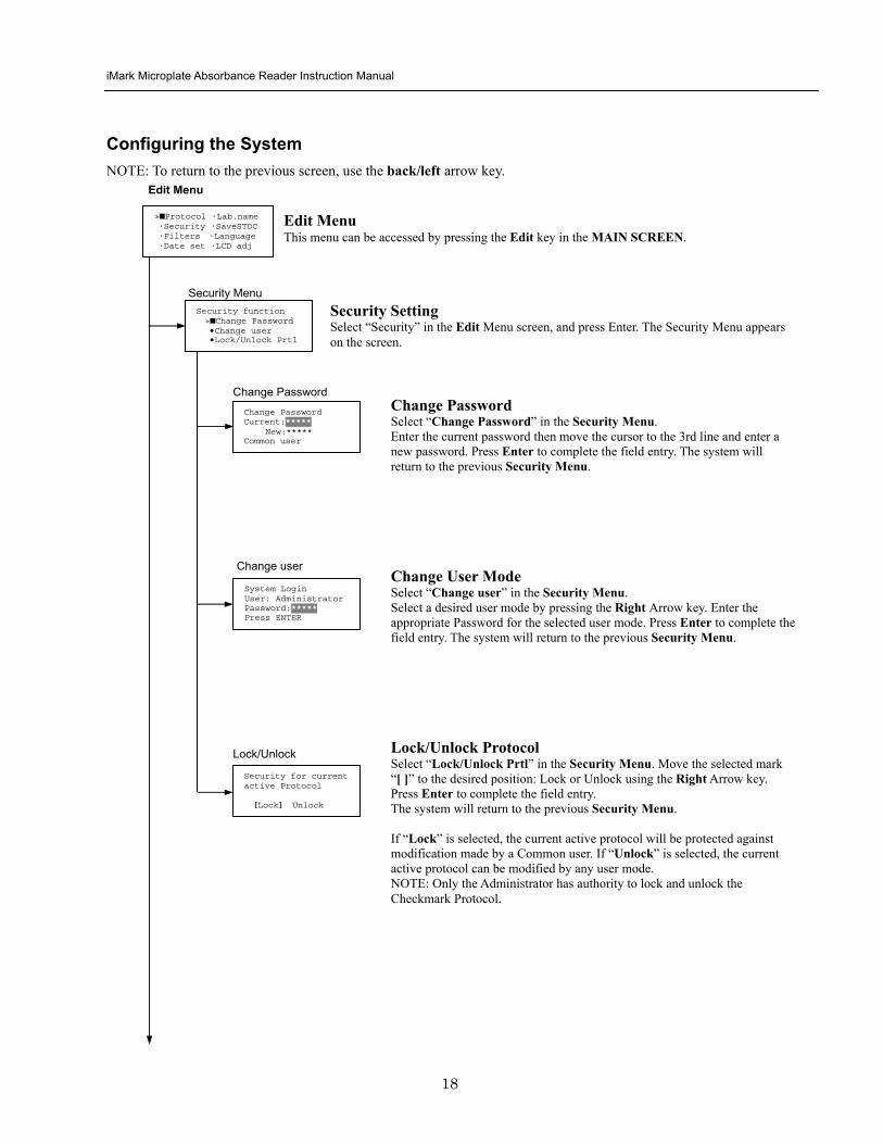
iMark Microplate Absorbance Reader Instruction Manual
19
1400nm 5650nm 2450nm 6nm 3475nm 7nm 4650nm 8nm
Filter
DayMonthYear 16 05 01 Hour Minutes 18 55
Date set
Enter Lab name Bio Rad Laboratories uarr [ABC]
Lab name
Filter Setting Move the cursor to the desired position by using the Up Down and Right arrow keys Enter the filter wavelength on the selected position using the number keys If the selected position of the filter disk is empty enter three ldquordquo Press Enter to complete the field entry The system will return to the previous Edit Menu screen
Calendar Setting Move the cursor to the desirable position for date or time input by using the Up Down and Right arrow keys Enter the present date or time using the number keys Press Enter to complete the field entry The system will return to the previous Edit Menu screen
Lab Name Setting Use the Up and Down arrow keys to select from ldquoArdquo to ldquoZrdquo and symbols Use the Number keys for numeric input Use the Right arrow key to move the cursor to the right Use the Left arrow key to return the cursor to the Edit Menu screen Pressing the FUNCrdquo key will toggle the character mode between Upper case alphabet Lower case alphabet and symbol The current character mode is indicated on the lower right corner of the LCD
Save STD Curve gt Save STD Curve Rename STD Curve
Save STDC Save STDC Setting Select ldquoSave STDCrdquo in Edit Menu screen above and press Enter The Save STD Curve Menu appears on the screen Move the cursor to the desired position by using the Up and Down arrow keys
Select STD storage gt 1120304 1500 2 3150304 1030
Select for renaming gt 1160304 1125 2 3150304 1030
Save STD Curve To save a STD Curve select the storage number between 1 and 5 Use the Up and Down arrow keys to move the cursor to the desired storage number and press Enter to complete the selection After the storage number selection the rdquoAre you surerdquo message appears Select ldquoYesrdquo or ldquoNordquo and press Enter In case of ldquoYesrdquo the reader saves the STD Curve and returns to the Edit Menu screen If the curve fit calculation is not done or has not finished successfully an error message will appear and the STD Curve will not be saved STD curve does not
exist yet Press any key
Save STD Curve 1160304 1125 Are you sure gt Yes No
Rename STD Curve To change a name of an STD Curve select a storage number between 1 and 5 Use the Up and Down arrow keys to move the cursor to the desired storage number and press Enter to complete the selection Use the Up and Down arrow keys to select from ldquoArdquo to ldquoZrdquo and symbol Use the Number keys for numeric input Use the Right arrow key to move the cursor to the right Use the Left arrow key to return the cursor to the Edit Menu screen Pressing the FUNCrdquo key will toggle the character mode between Upper case alphabet Lower case alphabet and symbol The current character mode is indicated on the lower right corner of the LCD
1160304 1125 gtSTD Curve 1 lt
[ABC]
Save STD Curve
Rename STD Curve
iMark Microplate Absorbance Reader Instruction Manual
20
Printing Reports and Protocol information
Print menu raquoReports bullProtocol
Print Menu Print Menu Access this menu screen by pressing the Print key in the MAIN screen Printing Reports Select ldquoReportsrdquo and press Enter to print the current active plate data report Printing Protocol Information Select ldquoProtocolrdquo and press Enter to print all parameter settings in the current active protocol Stop Printing Press the StartStop key during printing to stop the print job immediately When printing is completed the system automatically returns to the MAIN screen
Select Language raquoEnglish bull bull bull
Language Changing Language Select a desired language using the Up and Down arrow keys and press Enter to complete the selection The system will generate a message for an immediate power off to restart Select ldquoYesrdquo and press Enter to activate the selected new language The newly-changed language will be applied to the LCD screen and printed reports Power off
gtgtYes No
LCD Contrast 12345678901234567890
laquo 26 raquo ENTER to complete
Adjusting LCD Contrast Adjust LCD contrast by using the Right and Left arrow keys and press Enter to complete the adjustment
LCD adj
iMark Microplate Absorbance Reader Instruction Manual
21
Memory Recall Operation
01 200500 1400 02raquo210500 1700 03 200500 1800 darr04raquo200500 1900
01raquo200500 0900 02raquo200500 1000
Memory Recall raquoProtocol bullPlate Data
Protocol type menu
Data type menu
End Point
Kinetic
End Point
Kinetic
Memory Recall Menu
Select protocol type raquoEnd Point
bullKinetic bullCheckmark
Select Protocol 02 uarrraquo Protocol -2 Protocol -3 darr Protocol -4
Select Protocol 01 raquo Kinetic -1 GALT
Select data type raquoEnd Point
bullKinetic bullCheckmark
200501 0900
Checkmark
Checkmark program has been activated Press any key
Checkmark
Selecting Protocol Move the cursor to the position of the desired protocol and press Enter to complete the selection NOTE ldquordquo indicates the currently activated protocol and ldquordquo indicates a security locked protocol There is no protocol selection with ldquoCheckmarkrdquo When a protocol is selected the system will then automatically return to the MAIN screen
Changing Current Active Protocol Select ldquoProtocolrdquo in Memory Recall menu above and press Enter The Select Protocol type menu will appear on the screen Select a protocol using the Up and Down arrow keys Press Enter to complete the selection
Selecting Plate Data Move the cursor to the position of the desired plate data and press Enter to complete the selection NOTE ldquordquo indicates the currently activated plate data There is only one storage for ldquoCheckmarkrdquo data When plate data is selected the system automatically returns to the MAIN screen
Changing Current Active Plate Data Select ldquoPlate Datardquo using the Memory Recall button and press Enter The Data type menu will appear Use the Up and Down arrow keys to select a plate data type Press Enter to complete the selection
This menu screen can be accessed by pressing the Memory Recall key in the MAIN screen
iMark Microplate Absorbance Reader Instruction Manual
22
Editing the Kinetic Protocol
Select ldquoProtocolrdquo in the Edit Menu and press Enter The Kinetic Protocol menu will appear on the screen if the current active protocol type is Kinetic
Reading speed [Fast mode] Step mode
Speed
raquoReading Speed Inter Shaking Phmode
Kinetic Mode
Kinetic Protocol Menu
raquoMode Report Calc Kit name Mapping Assay
This menu screen can be accessed by selecting ldquoModerdquo in the Kinetic Protocol menu above
Number of Reading = 20 (2-30) Start Delay time = 25 sec(0-999)
Reading
Number of Reading = 2 Start Delay time = 25 sec(0-999)
Number of Readings and Start Delay Time Setting Press the Up or Down arrow key to change the number Enter the appropriate numbers with the numeral keys and press Enter to complete the field entry The system will return to the Kinetic Edit Menu If GALT is the current assay type the number of reading fields is fixed at 2 Press the StartStop key to set the Start Delay time enter a value and press Enter until the reading starts
1-gt2raquo 100 sec 2-gt3 100 sec 3-gt4 100 sec darr4-gt5 100 sec
Inter Use same interval between all reads
raquoYes No
Setting Reading Intervals The system prompts the operator to set a reading interval before each plate run Move the cursor to the desired selection ldquoYesrdquo or ldquoNordquo and press Enter The system generates the interval entry screen Move to the active entry field by pressing the Up and Down arrow keys and enter appropriate numbers using numeral keys Press Enter to complete all field entries The system will return to the Kinetic Mode menu
Photometric Dual Measurement405 nm Reference 655 nm
Ph mode Photometric Mode Setting When the ldquoPhotometricrdquo field is activated pressing the Right arrow key will switch the field entry ldquoSinglerdquo lt-gtrdquoDualrdquo Pressing the Up or Down arrow keys will move the cursor to the next entry field Pressing the Right arrow key when the wavelength field is activated will change the wavelength to the next available selection installed in the reader Press Enter to complete all field entries
Shaking parameters Before Every read Speed Mid Time 999 sec
Shaking Plate Shake Parameters When the ldquoBeforerdquo field is activated pressing the Right arrow key will change the field entry ldquoEveryrdquo-gtrdquo--rdquo-gtrdquoFirstrdquo-gt When the ldquoSpeedrdquo field is activated pressing the Right arrow key will change the field entry ldquoMidrdquo -gtrdquoHirdquo-gtrdquoLowrdquo-gt When the ldquoTimerdquo field is activated enter the time value for plate shaking period using the numeral keys Press Enter to complete all field entries
Selecting Reading Speed Use the Up or Down arrow keys to switch the selection Press Enter to complete the selection
Edit Menu raquoProtocol Labname Security bullSaveSTDC Filters bullPrinter Date set
This menu screen can be accessed by pressing the Edit key in the MAIN screen
iMark Microplate Absorbance Reader Instruction Manual
23
Kit name for 01 raquoGAP TEST IgGlaquo uarr [ABC]
Kit name
Calculation
Mapping
Assay
Assay type selection raquo[General KINETIC] GALT assay
Calculation Param CC Limit 0910
Calcrange 10 - 20
Select Mapping mode raquoManual mapping bullAutomatic mapping
raquo[Linregression] bullAbsorbance bullKINETIC Plots
Report
Plate Mapping See Plate Map setting procedure
Result = (R2 ndash R1)k k = 999999 R11st Reading R22nd Reading
If GALT
Setting the Kit Name Use the Up and Down arrow keys to select alphabet from ldquoArdquo to ldquoZrdquo and space Use the Number keys for numeric input Use the Right arrow key to move the cursor to the right Use the Left arrow key to return to the Protocol Menu screen Pressing ldquoFUNCrdquo key will change the character mode Upper case alphabet -gt Lower case alphabet -gt symbol The current character mode is indicated on the lower right corner of the LCD
Kinetic Protocol Menu
Selecting Kinetic Assay Type Move the cursor to the desired Assay type by pressing the Up or Down arrow keys Press Enter to complete the selection The item with mark ldquo[ ]rdquo is the currently selected item GALT assay Result = factor x (2nd Read ndash 1st Read)
Selecting Report Type Move the cursor to the desired report type by pressing the Up or Down arrow keys Pressing the Right arrow key will select or deselect the item Press Enter to complete the selection Note When GALT assay is selected ldquoGALT reportrdquo shall be the only one option on this screen
raquoMode bullReport bullCalc bullKit name bullMapping bullAssay
Calculation Parameter Setting When the ldquoCC Limitrdquo field is activated pressing the numeral key will enter the desired numbers Press Enter to complete all field entries If the GALT Reports is activated pressing the numeral keys will enter the desired numbers Press Enter to complete all field entries
iMark Microplate Absorbance Reader Instruction Manual
24
Checkmark Value Setting (Administrator only)
raquoSerial Report bullLinearity ref bullMaxCV bullFilter Check ref
Checkmark Protocol Menu
raquoSerial 0000 Reptype Simple
405nm S10158 Linearity S20309 reference S31401 S42109
MaxCV raquoS115 Linearity S205 reference S302 S402
Filter max min 4051875 0329 4501167 0954 darr 4920596 0103
Serial Report
Linearity reference
Max CV
Filter check reference
Filter max min uarr 5401875 0329 6201167 0954 6900596 0103
Setting the Serial Number and Report Type Pressing the Up and Down arrow keys will move the cursor and change the field entry When ldquoSerial rdquo field is active enter the serial number that will be shown in the data sheet of the Checkmark plate using the numeral keys When the ldquoRep typerdquo field is active pressing the Right arrow key will switch the report type between ldquoSimplerdquo and ldquoFullrdquo
Setting the Linearity Reference Value Pressing the Up or Down arrow keys will move the field entry from S1 to S4 Pressing the Right arrow key will change the wavelength 405 nm-gt450 nm-gt492 nm-gt540 nm-gt620 nm-gt690 nm Use the numeral keys for the reference value setting Pressing Enter will complete all field entries at all wavelength
Max CV setting Pressing the Up or Down arrow keys will move the field entry from S1 to S4 Use the numeral keys for the Max CV setting Press Enter to complete all field entries
Setting the Filter Check Reference Value Initial screen shows the reference entries for 405 nm to 492 nm and pressing the Down arrow key at the bottom of the screen entries will scroll to the next page for 540 nm to 690 nm Pressing the Up Down and Right arrow keys will move the field entry Use the numeral keys for the filter check reference value setting Press Enter to complete all field entries
Select ldquoProtocolrdquo in the Edit Menu and press Enter The Checkmark Protocol Menu will appear on the screen if the current active protocol type is Checkmark mode
Edit Menu raquoProtocol bullLabname bullSecurity bullSaveSTDC bullFilters bullPrinter bullDate set
This menu screen can be accessed by pressing the Edit key in the MAIN screen
iMark Microplate Absorbance Reader Instruction Manual
25
Editing End Point Protocol
Upper Limit= 2000 Lower Limit= 0000 input range 0ndash3500 Upper gt Lower
Standard menu raquoSTD information
bullCurvefit bullRecall STD Curve
raquoCutoff bullMode bullReport bullMapping bullLimit bullKit name bullSTDs
Cutoff
See Plate Map setting procedure
See Standard setting procedure
See Mode setting procedure
raquo[Not use] bullRatio bullConstant bullContrl bullFormula
raquoSet photo mode bullSet shaking bullSet read mode
Select mapping mode raquoManual mapping bullAutomatic mapping
Mapping
Mode
Report
STDs
Limit
Kit name for 01 raquoGAP TEST IgGlaquo uarr [ABC]
Kit name See Kit name setting in Editing Kinetic Protocol
See Cutoff setting procedure
Select ldquoProtocolrdquo in Edit Menu screen above and press Enter The End point Protocol Menu will appear on the screen if the current active protocol type is End point mode
End Point Protocol Menu
raquo[Raw] bullMtx bullCnc bullAbs bullCut bullDif bullLim bullCrv
If ldquoDifrdquo selected
[Raw] bullMtx bullCncbullAbs bullCut [Dif] bullLim bullCrv raquorow odd-even
Seting the Report Type Use the Up and Down Arrow key to move the cursor and press the Right Arrow key to select or deselect the report type Selected report type is marked as ldquo[ ]rdquo Press Enter to complete the selection
Setting the Limit Value Use the Up and Down Arrow key to move the cursor and enter the OD value using the numeral keys The OD value range is 0000 - 3500 Press Enter to complete the selection
Edit Menu raquoProtocol bullLabname bullSecurity bullSaveSTDC bullFilters bullPrinter bullDate set
This menu screen can be accessed by pressing the Edit key in the MAIN screen
iMark Microplate Absorbance Reader Instruction Manual
26
Cutoff Setting Procedure
Cutoff Setting Menu This menu is entered by choosing Cutoff in the End Point Protocol Menu It is used to set the cutoff type The cutoff type marked with ldquo[ ]rdquo is the current selection The Up and Down arrow keys move the cursor to the desired item in the menu list When the desired parameters have been selected press Enter twice to accept the selection and to continue to the next screen Not use means that the reader does not generate the cutoff report Four types of cutoff are supported
1 Cutoff Constant 2 Cutoff Control 3 Cutoff Formula 4 Cutoff Ratio
a Cutoff Constant
Selection of SingleRanged Cutoff Constant This menu selects Single or Ranged cutoff type The cutoff type marked with ldquo[ ]rdquo is the current selection The Enter key seals the selection and resumes to the next setting screen
Single Cutoff Constant The Numerical keys and the Decimal point key are used to enter the positive and gray zone values The Right arrow key is used to select the unit The Up and Down arrow keys move the cursor to the desired parameter of the single cutoff The Enter key sets all values and selection of the cutoff constant and returns the user to the previous screen Ranged Cutoff Constant The Numerical keys and the Decimal point key are used to enter the positive and negative values The Right arrow key is used to select the unit The Up and Down arrow key moves the cursor to the desired ranged cutoff parameters The Enter key sets all values and selection of the cutoff constant and returns to the previous screen NOTE Two available Cutoff constants are ldquoAbsorbancerdquo and ldquoConcentrationrdquo If Abs is chosen the Absorbance cutoff will be done with the cutoff constant parameters defined and the absorbance report is generated For other units defined in the curve fit setting the Concentration value using the curve fit and then cutoff is done with the cutoff constant parameters defined and the concentration value of each well It is necessary to set the curve fit parameters
raquoNot usex bullRatio [Const] bullContrl bullFormula
raquoPositive gt= 9999 Gray zone 50 Unit moll
raquoPositive gt= 9999 Negative lt 1999 NegativeltPositive Unit moll
raquoRanged cutoff [Single cutoff]
Single cutoff
Ranged
iMark Microplate Absorbance Reader Instruction Manual
27
b Cutoff Control
Selection of SingleRanged Cutoff Control This menu screen selects Single or Ranged cutoff type The cutoff type marked with ldquo[ ]rdquo is the current selection The Enter key seals the selection and resumes to the next setting screen
Single Cutoff Control The Numerical keys are used to enter the gray zone value The unit is fixed to Abs The Enter key sets the value of the cutoff control and returns to the previous screen Ranged Cutoff Control There is no parameter to set for the ranged cutoff control The Enter key returns to the previous screen NOTE CNx is the mean absorbance value of Negative control wells and CPx is the mean absorbance value of Positive control wells These wells are defined in the plate map setting The cutoff is done with the Positive and Negative value to the absorbance value of each well
c Cutoff Formula
Selection of Formula This menu screen selects a formula for cutoff calculation The formula marked with ldquo[ ]rdquo is the current selection The Up and Down arrow keys move the cursor to the desired formula type The movement of the cursor follows the scroll of this screen The Enter key marks the selection and advances the user to the next setting screen The supported formula types are
1 k CNx 2 k CPx 3 k COx 4 CNx k 5 CPx k 6 COx k 7 k + CNx 8 k + CPx 9 k + COx 10 kCNx + CPx 11 ( CNx + CPx ) k 12 k1CNx + k2CPx
Coefficient for Cutoff Formula 1 to 11 The Numerical keys and the Decimal point key are used to enter the coefficient k and gray zone values The Up and Down arrow key moves the cursor to the desired parameter of the cutoff formula The Enter key sets all values of the cutoff formula and returns to the previous screen
Positive gt= CNx Gray zone 50 Unit Abs
Positive gt= CPx Negative lt CNx Unit Abs
Enter key to accept
raquoRanged cutoff [Single cutoff]
Single cutoff
Ranged
Input coefficient k = 001 (001-10) Gray zone 50(0-99)
k CNx k CPx k COx CNx k CPx k COx k k + CNx k + CPx k + COx k CNx + CPx (CNx + CPx) k
uarr raquoCNx k bullCPx k bullCOx k darr bullk + CNx
Select formula raquo[kCNx ] bullkCPx darr bullkCOx
uarr raquok + CPx bullk + COx bullkCNx + CPx darr bull(CNx + CPx) k
uarr raquok1CNx + k2CPx
Page-1
Page-2
Page-3
Page-4
iMark Microplate Absorbance Reader Instruction Manual
28
Coefficient for Cutoff Formula 12 The Numerical keys and the Decimal point key are used to enter the coefficient k1 and k2 and gray zone values The Up and Down arrow key moves the cursor to the desired cutoff formula The Enter key sets the all values of the cutoff formula and returns to the previous screen NOTE CNx is the mean absorbance value of Negative control wells CPx is the mean absorbance value of Positive control wells and COx is the mean absorbance value of Cutoff control wells These wells are defined on the plate map setting The cutoff value is calculated using the defined formula with the defined values and coefficients
d Cutoff Ratio
Ratio to Calibrator In this screen there are three items for setting the ratio to calibrator The Up and Down arrow key moves the cursor to the desired item in the menu list The Enter key seals the selection and resumes to the next setting screen
Concentration of Calibrator The Numerical keys and the Decimal point key are used to enter the calibrator concentration value The Enter key sets the value and returns to the previous screen Unit of Calibrator Seventeen standard units are supported The unit marked with ldquo[ ]rdquo is the current selection The setting procedure is the same as the unit selection of Standards Cutoff Value Setting This menu screen selects Single or Ranged cutoff type The cutoff type marked with ldquo[ ]rdquo is the current selection The Enter key marks the selection and continues to the next setting screen Single Cutoff Control The Numerical keys are used to enter the Positive cutoff concentration value and gray zone value The Enter key sets these cutoff ratio values and returns to the previous screen Ranged Cutoff Control The Numerical keys are used to input the Positive and the Negative cutoff concentration values The Enter key sets these cutoff ratios and returns to the previous screen NOTE The calibrator concentration value is used to convert the absorbance value of each well into a concentration value The ratio of ConcentrationAbsorbance of Calibrator well is applied to the conversion The cutoff uses defined Positive and Negative values to the converted concentration value of each well
Input coefficient k1 = 001 (001-10) k2 = 100 (001-10) Gray zone 50(0-99)
k1 CNx + k2 CPx
Ratio to Calibrator raquoConcentration bullUnit bullCutoff value
Concentration 9999 unit moll
uarrraquo 01 ugdl 02 ngml 03[ pgml] darr 04 pmml
raquoPositive gt= 9999 Gray zone 50
Unit moll
raquoPositive gt= 9999 Negative lt 9999 NegativeltPositive
Unit moll
raquoRanged cutoff [Single cutoff]
Concentration
Unit
Cutoff value
Single cutoff
Ranged cutoff
iMark Microplate Absorbance Reader Instruction Manual
29
Standard Setting Procedure
Standard Curve Setting Menu This menu screen is entered by choosing STDs in the End Point Protocol Menu screen It is used to set the concentration data and the curve fit type for a standard curve or to recall a memorized standard curve The Up and Down arrow key moves the cursor to the desired item in the menu list The Enter key seals the selection and continues to the next setting screen
a STD Information Setting
STD Information In this screen there are three items for setting the concentration data of standards The Up and Down arrow keys move the cursor to the desired item in the menu list The Enter key seals the selection and continues to the next setting screen
Number of Standards The Numerical keys are used to enter the number of standards ldquo0rdquo means that the curve fit report is not used The Enter key sets the number and returns to the previous screen The maximum number of standards is 12 Concentration The Numerical keys and the Decimal point key are used to enter the concentration values of standards The Up and Down arrow keys move the cursor to the desired position The movement of the cursor also follows the scroll of this screen The Enter key sets all values of the concentration of standards and returns to the previous screen Unit Seventeen units are supported The unit marked with ldquo[ ]rdquo is the current selection The Up and Down arrow keys move the cursor to the desired unit type The movement of the cursor also follows the scroll of this screen Press Enter twice to select the unit type and to return to the previous screen The supported types of unit are
1 moll 11 pgml 2 m moll 12 Uml 3 u moll 13 IUml 4 n moll 14 uIUml 5 p moll 15 mIUml 6 mgl 16 EU 7 ngl 17 Arbit 8 pgl 9 ugdl 10 ngml
STD information raquoNumber of STD bullConcentration bullUnit
STD 1 0512 STD 2 1012 STD 3 1512 darr STD 4 2053
Standard menu raquoSTD information bullCurve fit bullRecall STD curve
Concentration
Number of STD
Number of STD = 05 (0 2ndash12)
uarrraquo 01 ugdl 02 ngml 03[ pgml] darr 04 pmml
Unit
iMark Microplate Absorbance Reader Instruction Manual
30
b Curve Fit Setting
Curve Fit In this screen there are two choices to set the curve fit The Up and Down arrow keys move the cursor to the desired item in the menu list The Enter key seals the selection and resumes to the next setting screen
Curve Fit Type 10 types of curve fit are supported as below The curve fit type marked with ldquo[ ]rdquo is the current selection The Up and Down arrow key moves the cursor to the desired curve fit type The movement of the cursor follows the scroll of this screen Press Enter twice to select the unit type and to return to the previous screen The supported curve fit types are
1 5P Logistic Rodbard 2 4P Logistic Rodbard 3 5P Logistic Cook-Wilkenson 4 4P Logistic Cook-Wilkenson 5 5P Exponential 6 Sigmoid Logistic 7 Linear regression 8 Quadratic regression 9 Cubic 10 Point To Point regression
Graph Axis Four types of graph are supported The curve fit type marked with ldquo[ ]rdquo is the current selection The Up and Down arrow keys move the cursor to the desired graph type Press Enter twice to select the unit type and to return to the previous screen The supported graph types are
1 Log - Log 2 Log - Linear 3 Linear - Log 4 Linear - Linear
uarr 5p logisticRodb raquo 4p logisticRodb [5p logisticCook] darr 4p logisticCook
raquo X-Log Y-Log [X-Log Y-Lin] X-Lin Y-Log X-Lin Y-Lin
Curve fit type
Graph axis
Curve fit setting raquoCurve fit type bullGraph axis
iMark Microplate Absorbance Reader Instruction Manual
31
c Recall STD Curve Setting
Recall Setting of Standard Curve In this screen there are two items for setting the Recall STD curve as below The Up and Down arrow keys move the cursor to the desired item in the menu list
1 Recall setting (YesNo) 2 Selecting the storage number of standard curves (1 -gt 5)
Recall Setting Move the cursor to the desired position using the Up Down or Right arrow keys Enter key accepts the setting and returns the user to the standard menu screen
Yes Recalling of the standard curve is active No Recalling of the standard curve is inactive
Storage Number Selection Five memories are selectable The vacant memory (marked with asterisks on the date and time field) is also selectable It is necessary to save a standard curve before using its protocol Move the cursor to the desired position using the Up and Down keys This setting screen consists of two parts The Right arrow key is used to switch the indication field between the date and time to the standard curve name Move the cursor to the desired position using the Up and Down keys The Enter key accepts the storage number and returns to the standard menu screen NOTE If the recall of standard curve is active (the recall setting is ldquoYesrdquo) the standard information setting and the curve fit setting will be invalidated and their setting screens will not open
Recall STD curve raquoRecall setting bullSelect STD curve
Recall setting raquoYes No
Recall setting
Select STD Curve raquo1160304 1125
2 darr 3150304 1030
Select STD Curve uarrraquo4
5
Select STD Curve raquo1 STD Curve 1
2 STD Curve 2 darr 3 STD Curve 3
Select STD Curve uarrraquo4 STD Curve 4
5 STD Curve 5
Select STD curve
Right arrow key
iMark Microplate Absorbance Reader Instruction Manual
32
Mode Setting Procedure
Mode Setting Menu This menu screen is entered by choosing the Mode in the End Point Protocol Menu screen or the Kinetic Protocol Menu screen It is used to set the plate reading conditions The Up and Down arrow keys move the cursor to the desired item in the menu list The Enter key seals the selection and resumes to the next setting screen
a Set Photo Mode
Photo Mode In this screen the user chooses Single or Dual wavelength measurement and assigns the measurement and reference (for dual wavelength measurement) filters The assignment of the reference filter appears for dual wavelength measurement The Up and Down arrow keys move the cursor to the desired parameter The Right arrow key chooses SingleDual wavelength measurement and selects the installed filter on the Filters of Edit Menu screen The Enter key seals the selection and returns to the previous screen
b Set Shaking
Shaking In this screen the user selectsdeselects shaking function sets the shaking strength and enters the shaking time A shaking time of 0s indicates no shaking The maximum shaking time is 999 seconds The Up and Down arrow key moves the cursor to the desired parameters The Right arrow key toggles between YesNo (SelectDeselect) shaking or selects strength LowMiddleHigh The Numerical keys are used to enter the shaking time The Enter key seals the selection and returns the user to the previous screen
c Set Read Mode
Read Mode In this screen the user chooses Fast or Step reading and also chooses Normal or Evaluation mode The ldquo[ ]rdquoindicates the current selection The Up and Down arrow key moves the cursor to the desired parameters The Right arrow key chooses FastStep speed or chooses NormalEval mode The Enter key seals the selection and returns to the previous screen The followings are the description of each read mode parameter Reading speed
Fast reading 6 secsingle wavelength reading 10 secdual wavelength reading
Step reading 15 secsingle wavelength reading 30 secdual wavelength reading
Reading mode
Normal mode Plate reading once Evaluation mode Four plate readings per one of measurement are performed and
the average data of their plate readings is generated as a plate data
Photometric Dual Measurement400 nm Reference 655 nm
Set Shake parameters ShakeYes SpeedMid Time 199sec(0-999)
raquoReading speed [Fast ] Step bullRead mode [Normal] Eval
raquoSet Photo mode bullSet shaking bullSet read mode
Photometric Single Measurement400 nm
iMark Microplate Absorbance Reader Instruction Manual
33
Plate Map Setting Procedure
Select Mapping Mode Menu This menu screen is entered by choosing Mapping in the End Point Protocol Menu screen or the Kinetic Protocol Menu screen It is used to map the plate format The Up and Down arrow keys move the cursor next to the desired item of menu list The Enter key seals the selection and changes this screen to the next setting screen
a Manual Mapping
Manual Mapping In this screen the user can set the plate format manually Ten well types can be set Well types The supported well types are
Well type Indication on LCD
1 Blank B 2 Sample X00hellipX99 3 Standard S01hellipS99 4 In-kit Control Positive Control CP0hellipCP9 5 Weak Positive Control CW0hellipCW9 6 Negative Control CN0hellipCN9 7 Cutoff Control CO0hellipCO9 8 Calibrator CL0hellipCL9 9 QC Control QC0hellipQC9 10 Empty well -
The key assignments of well type are ldquo0EMPrdquo Empty well ldquo5QCrdquo Quality Control well ldquo1SMPrdquo Sample well ldquo6CALrdquo Calibrator well ldquo2BLKrdquo Blank well ldquo7CPrdquo Positive Control well ldquo3STDrdquo Standard well ldquo8CNrdquo Negative Control well ldquo4COrdquo Cutoff Control well ldquo9CWrdquo Weak Positive Control well
Two Edit Modes in Plate Mapping There are two editing modes for well type input mode and for well number input The current input mode is displayed at the upper left corner of the screen When using the well type input mode the mode sign is ldquo[F]rdquo When using the well number input mode the mode sign is ldquoNrdquo The cursor that encloses the editing position of well has two types of enclosures depending on the mode For example ldquo[S01]rdquo accepts the well type keys that be assigned to the numerical keys and ldquoS01rdquo accepts the numerical input The mode is easily changed with the Decimal point key Key Functions The Up Down Right and Left arrow keys move the cursor to the desired well The movement of the cursor follows the scroll of this screen The Left arrow key will return the screen to the preceding screen or the select Mapping mode Menu only if the cursor is on column 1 At this time the selection screen appears (see the left figure) The Decimal point key changes the input mode The Numerical keys have two functions one to input the number and another to select a well type The Enter key checks the consistency between the edited plate map and other parameters memorizes the plate map into the protocol and changes this screen back to the preceding screen If it finds any inconsistency a warning message will appear on the screen
Select Mapping mode raquoManual mapping bullAutomatic mapping
N 1 2 3 4 A B CN1 S01 S01 B B CN1 S02 S02 C B CN2 S03 S03 [F] 5 6 7 8 A X11 X12 X13 X14 B X21 X22 X23 X24 C X31 X32 X33[X34]
Discard change 1Yes 2No Press 1 or 2 key
iMark Microplate Absorbance Reader Instruction Manual
34
Acceptable Number Ranges for each well type 1 Blank and Empty wells do not use numbers 2 Sample and Standard wells 00 - 99 3 Standard wells 01 - 99 4 Control and Calibrator wells 0 - 9
b Automatic Mapping
Automatic Mapping The user can input the number of each well type in this screen These defined numbers are used to set a plate map automatically Well type Nine well types are available
1 BLK Blank (0-gt10) 2 CN Control CN (0-gt9) 3 CW Control CW (0-gt9) 4 CP Control CP (0-gt9) 5 CO Control CO (0-gt9) 6 QC Control QC (0-gt9) 7 CAL Calibrator (0-gt9) 8 SMP Sample (0-gt96) 9 REP Replicate well (1-gt4)
It is possible to define the number of blanks samples calibrators and controls But the number of Standards is not included because standards are defined at the Standard Setting Menu The number of replicate wells is also included It is used for replicating each well type individually Key Functions The Up Down Right and Left arrow keys are used to move the cursor to the next position The Numerical keys are used to input the mapping parameters The Enter key accepts the mapping parameters and sets a plate map automatically using these parameters During the execution of the plate mapping the Plate auto-mapping completed message appears on the screen After that the user returns automatically to the previous Protocol Menu screen If the Left arrow key is pressed at the left end position of the cursor the left figure will appear on the screen If the user chooses Yes the system will return to the previous Protocol Menu screen If the user chooses No the system will stay in this setting screen Assigning Order and Direction of plate mapping Assigning Order The order of blanks standards samples calibrators and controls are fixed as follows Numbering for standards samples calibrators and controls is started at 1
1 Blank 2 Standard 1 -gt12 ---- NOTE 3 Control CN 1-gt9 4 Control CW 1-gt9 5 Control CP 1-gt9 6 Control CO 1-gt9 7 Control QC 1-gt9 8 Calibrator 1-gt9 9 Sample 1-gt96 10 Empty well NOTE If ldquoCutoff Controlrdquo ldquoValue by Formulardquo or ldquoRatio to Calibratorrdquo is
selected for the Cutoff plate mapping skips arranging the standards Assigning Direction The placing direction of the mapping is limited to the column direction as below
Column direction A1 -gt H1 A2 -gt H2 ----- A12 -gt H12
Discard change 1Yes 2No Press 1 or 2 key
Automatic mapping BLK= 1 CP = 1 CAL= 0 CN = 1 CO = 0 SMP=93 CW = 0 QC = 0 REP= 1
Plate auto-mapping completed
iMark Microplate Absorbance Reader Instruction Manual
35
Warning and Error of Automatic Mapping Warning screen If the total number of wells mapped exceeds 96 wells a warning message in the left figure appears on the screen The calculation of the total number of mapping wells is as follows
(Blanks+Standards+CNs+CWs+CPs+COs+QCs+Calibrators+Sample)Replicates The plate mapping is executed normally and the exceeded part is invalidated Error screen If one or more mapping parameters are over the input range an error message in the left figure will appear on the screen On the third line of the LCD the name of the parameter which is out of range and its input range will appear
Example ldquoBLK 0 ndash 10rdquo In case there is more than one error the first parameter of errors is indicated By pressing any key the user returns to the automatic mapping screen Example of automatic mapping An example of automatic mapping is as below 1 Conditions of each parameter
Blank = 1 Standard = 8 Control CN = 2 CW = 0 CP = 2 CO = 0 QC = 0 Calibrator = 1 Sample = 32 Replicate number = 2
2 Plate mapping data
1 2 3 4 5 6 7 8 9 10 11 12 A B C D E F G H
B B S1 S1 S2 S2 S3 S3
S4 S4 S5 S5 S6 S6 S7 S7
S8 S8 CN1 CN1 CN2 CN2 CP1 CP1
CP2 CP2 CL1 CL1 X1 X1 X2 X2
X3 X3 X4 X4 X5 X5 X6 X6
X7 X7 X8 X8 X9 X9 X10 X10
X11 X11 X12 X12 X13 X13 X14 X14
X15 X15 X16 X16 X17 X17 X18 X18
X19 X19 X20 X20 X21 X21 X22 X22
X23 X23 X24 X24 X25 X25 X26 X26
X27 X27 X28 X28 X29 X29 X30 X30
X31 X31 X32 X32 E E E E
Warning The total Of mapped wells has Exceeded 96 Press any key
Entered value is Out of range BLK 0 ndash 10 Press any key
iMark Microplate Absorbance Reader Instruction Manual
36
Instrument Maintenance
Caution Electrical shock hazard Always disconnect the instrument from the AC power source before opening the service compartment
Caution The lamp and the lamp cover may be very hot Use caution and allow the lamp to cool
before attempting service
Installing Interference Filters 1 With the power off open the rear cover of the instrument by pressing the
release latch located on the top left portion of the cover 2 Locate the filter wheel on the left side of the instrument Note that the
filter wheel has eight filter positions 3 Rotate the filter wheel to the desired filter Grasp the top of filter frame
and pull up to remove the filter 4 Insert the new filter into the desired filter position 5 Ensure that the new filter is added to the filter list as follows Main
menu-gtEdit-gtFilters
Changing the Lamp 1 With the power off open the rear cover of the instrument by pressing the
release latch located on the top left portion of the cover 2 Remove the two screws on the black plastic cover and carefully remove
the plastic cover 3 Remove the screw on the metal cover Lift the cover up and away from
the instrument This will allow the lamp to be pulled free from the lamp housing
4 Holding the ceramic base in one hand and the lamp housing in the other carefully pull the lamp free of the base
5 Carefully insert the new lamp firmly in the ceramic base Apply even pressure when inserting the lamp so that the bulb dose not become misaligned in the reflector housing Be extremely careful not to touch the front glass of the lamp during installation
6 Position the new lamp into the housing so that the plastic guides hold the flange of the lamp
7 Carefully place the metal cover over the lamp Tighten the screw 8 Replace the plastic cover and tighten the screws 9 Close the rear cover
iMark Microplate Absorbance Reader Instruction Manual
37
Troubleshooting and Error Messages
The iMark Microplate Reader constantly monitors several functions and displays appropriate messages on the LCD as errors are encountered
Error Recommendation
LCD appears blank on power up
a Power is not turned on The AC outlet is non-functional
b Unit is not plugged into AC outlet or power code is not attached to the instrument
Check power cord connections at outlet and on the rear panel of the instrument
1
c The AC outlet is non-functional Check circuit breakers or fuses
Instrument displays ldquoLight bulb errorrdquo message indicating that the bulb is burned out
Check whether lamp is emitting light
a Lamp is not emitting light Replace the lamp as described in x
2
b Lamp is emitting light Check the alignment of the lamp in the housing Align or replace the lamp if necessary
Printer will not print on command
3
a Printer paper is not installed properly Verify that the paper is properly installed Refer to x for details
Plate carriage jams during reading and ldquoPlate carrier errorrdquo is displayed
a Plate is not seated in carriage properly Press the STOP button immediately Position the plate carefully in the carriage making certain that it is properly seated
4
b Plate height is exceeding 16mm Use Microplate which is less than 16mm in height
5 LCD displays ldquoFilter missingrdquo Install a filter in the empty position Select the installed filter by pressing Edit key
6 LCD displays ldquoFilter disk jammedrdquo indicating that the filter wheel is not turning freely
Turn off the instrument and inspect the filter wheel Turn by hand to verify that the wheel is moving freely Make sure all the filters are properly installed and firmly seated Contact your Bio-Rad representative if the filter wheel is jammed or if the problem persists
7 LCD displays ldquoFilter not installedrdquo Enter the Edit Menu by pressing Edit key and set up the filters
iMark Microplate Absorbance Reader Instruction Manual
38
Wells have color but absorbance values seem low
a Incorrect filter used for measurement andor reference wavelength
Check wavelength used in analysis Read plate in single wavelength mode at all wavelength to verify that the proper filter was used The measurement wavelength should produce the highest absorbance
b The best measurement wavelength filter for the substrate in use has not been installed in the filter wheel
Check references for the substrate you are using or determine the best measurement wavelength by analyzing the substrate product on a scanning spectrophotometer Custom filters are available from 400 to 750 nm
8
c The filters have been switched in the wheel Check that the filters are installed in the correct position
9 ldquoPrinter errorrdquo displayed Check for paper jam Install the printer paper correctly
10 ldquoBattery errorrdquo displayed The internal battery is almost dead Contact your local Bio-Rad office
11 The following messages are displayed ldquoMemory errorrdquo ldquoCalendar errorrdquo ldquoLCD hardware errorrdquo ldquoPrinter errorrdquo ldquoLight level errorrdquo ldquoDA conversion errorrdquo ldquoAD conversion errorrdquo ldquoEEPROM errorrdquo ldquoUSB errorrdquo
Contact your local Bio-Rad office if these problems persist
iMark Microplate Absorbance Reader Instruction Manual
39
Instrument Specifications Computer interface USB 20
Plate shaking 3 speeds (low mid high) Programmable time period 0 - 999 seconds
Data storage The most recent 10 data plates for end-point most recent 2 data plates of 30 readings for kinetic readings protocol data and calendarclock function shall be kept in memory by a lithium battery even when the power is off Average lifetime of the battery shall be 5 years
Warm-up time 3 minutes
Photometric Methods Single and dual wavelength
Photo detectors 8 silicon photodiodes for measurement and 1 silicon photodiode for reference
Light source Tungsten halogen lamp 20W with 3000 hours average lifetime
Spectral range 400 nm to 750 nm
Interference filters Wavelength tolerance plusmn30 nm Band width 10 nm typically
Filter capacity 8 filters
Reading speed Fast Reading 6 sec with single wavelength reading 10 sec with dual wavelength reading
Step Reading 15 sec with single wavelength reading 25 sec with dual wavelength reading
These times are minimum interval times between repetitive reads using onboard KINETIC protocol
Indication range 0000 to 35 OD
Resolution 0001 OD
Accuracy plusmn10 or 0010 from 0 to 30 OD at 490 nm
Linearity plusmn10 from 0 to 20 OD plusmn20 from 0 to 30 OD
Reproducibility 10 or 0005 OD from 0 to 20 OD 15 from 20 to 30 OD
Inter-channel variability 15 or 0005 OD from 0 to 30 OD
Stability and Drift 0010 OD at OD=1 with single wavelength reading
Built-in Printer Thermal printer Paper width 80mm
Line Voltage Universal input 100 - 240 VAC 5060Hz
Power consumption (max) 100 VA max
Dimensions (W x D x H 346 mm x 377 mm x 164 m mm
Weight 55 kg
Operating Environment 15ordmC - 40ordmC up to 90 relative humidity without condensation
Storage Temperature 10ordmC - 50ordmC up to 90 relative humidity without condensation
Life ScienceGroup
07-0816 0108 Sig 120710013301i Rev A USEG
Bio-RadLaboratories Inc
Web site wwwbio-radcom USA 800 4BIORAD Australia 61 02 9914 2800 Austria 01 877 89 01 Belgium 09 385 55 11 Brazil 55 21 3237 9400 Canada 905 364 3435 China 86 21 6426 0808 Czech Republic 420 241 430 532 Denmark 44 52 10 00 Finland 09 804 22 00 France 01 47 95 69 65Germany 089 318 84 0 Greece 30 210 777 4396 Hong Kong 852 2789 3300 Hungary 36 1 455 8800 India 91 124 4029300 Israel 03 963 6050 Italy 39 02 216091 Japan 03 6361 7000 Korea 82 2 3473 4460 Mexico 52 555 488 7670 The Netherlands 0318 540666 New Zealand 0508 805 500 Norway 23 38 41 30 Poland 48 22 331 99 99 Portugal 351 21 472 7700 Russia 7 495 721 14 04 Singapore 65 6415 3188 South Africa 27 861 246 723 Spain 34 91 590 5200 Sweden 08 555 12700 Switzerland 061 717 95 55 Taiwan 886 2 2578 7189 United Kingdom 020 8328 2000
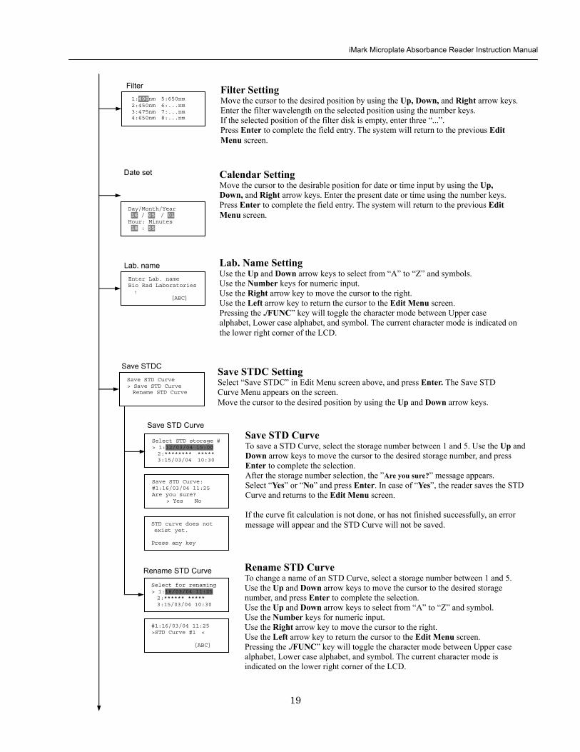
iMark Microplate Absorbance Reader Instruction Manual
20
Printing Reports and Protocol information
Print menu raquoReports bullProtocol
Print Menu Print Menu Access this menu screen by pressing the Print key in the MAIN screen Printing Reports Select ldquoReportsrdquo and press Enter to print the current active plate data report Printing Protocol Information Select ldquoProtocolrdquo and press Enter to print all parameter settings in the current active protocol Stop Printing Press the StartStop key during printing to stop the print job immediately When printing is completed the system automatically returns to the MAIN screen
Select Language raquoEnglish bull bull bull
Language Changing Language Select a desired language using the Up and Down arrow keys and press Enter to complete the selection The system will generate a message for an immediate power off to restart Select ldquoYesrdquo and press Enter to activate the selected new language The newly-changed language will be applied to the LCD screen and printed reports Power off
gtgtYes No
LCD Contrast 12345678901234567890
laquo 26 raquo ENTER to complete
Adjusting LCD Contrast Adjust LCD contrast by using the Right and Left arrow keys and press Enter to complete the adjustment
LCD adj
iMark Microplate Absorbance Reader Instruction Manual
21
Memory Recall Operation
01 200500 1400 02raquo210500 1700 03 200500 1800 darr04raquo200500 1900
01raquo200500 0900 02raquo200500 1000
Memory Recall raquoProtocol bullPlate Data
Protocol type menu
Data type menu
End Point
Kinetic
End Point
Kinetic
Memory Recall Menu
Select protocol type raquoEnd Point
bullKinetic bullCheckmark
Select Protocol 02 uarrraquo Protocol -2 Protocol -3 darr Protocol -4
Select Protocol 01 raquo Kinetic -1 GALT
Select data type raquoEnd Point
bullKinetic bullCheckmark
200501 0900
Checkmark
Checkmark program has been activated Press any key
Checkmark
Selecting Protocol Move the cursor to the position of the desired protocol and press Enter to complete the selection NOTE ldquordquo indicates the currently activated protocol and ldquordquo indicates a security locked protocol There is no protocol selection with ldquoCheckmarkrdquo When a protocol is selected the system will then automatically return to the MAIN screen
Changing Current Active Protocol Select ldquoProtocolrdquo in Memory Recall menu above and press Enter The Select Protocol type menu will appear on the screen Select a protocol using the Up and Down arrow keys Press Enter to complete the selection
Selecting Plate Data Move the cursor to the position of the desired plate data and press Enter to complete the selection NOTE ldquordquo indicates the currently activated plate data There is only one storage for ldquoCheckmarkrdquo data When plate data is selected the system automatically returns to the MAIN screen
Changing Current Active Plate Data Select ldquoPlate Datardquo using the Memory Recall button and press Enter The Data type menu will appear Use the Up and Down arrow keys to select a plate data type Press Enter to complete the selection
This menu screen can be accessed by pressing the Memory Recall key in the MAIN screen
iMark Microplate Absorbance Reader Instruction Manual
22
Editing the Kinetic Protocol
Select ldquoProtocolrdquo in the Edit Menu and press Enter The Kinetic Protocol menu will appear on the screen if the current active protocol type is Kinetic
Reading speed [Fast mode] Step mode
Speed
raquoReading Speed Inter Shaking Phmode
Kinetic Mode
Kinetic Protocol Menu
raquoMode Report Calc Kit name Mapping Assay
This menu screen can be accessed by selecting ldquoModerdquo in the Kinetic Protocol menu above
Number of Reading = 20 (2-30) Start Delay time = 25 sec(0-999)
Reading
Number of Reading = 2 Start Delay time = 25 sec(0-999)
Number of Readings and Start Delay Time Setting Press the Up or Down arrow key to change the number Enter the appropriate numbers with the numeral keys and press Enter to complete the field entry The system will return to the Kinetic Edit Menu If GALT is the current assay type the number of reading fields is fixed at 2 Press the StartStop key to set the Start Delay time enter a value and press Enter until the reading starts
1-gt2raquo 100 sec 2-gt3 100 sec 3-gt4 100 sec darr4-gt5 100 sec
Inter Use same interval between all reads
raquoYes No
Setting Reading Intervals The system prompts the operator to set a reading interval before each plate run Move the cursor to the desired selection ldquoYesrdquo or ldquoNordquo and press Enter The system generates the interval entry screen Move to the active entry field by pressing the Up and Down arrow keys and enter appropriate numbers using numeral keys Press Enter to complete all field entries The system will return to the Kinetic Mode menu
Photometric Dual Measurement405 nm Reference 655 nm
Ph mode Photometric Mode Setting When the ldquoPhotometricrdquo field is activated pressing the Right arrow key will switch the field entry ldquoSinglerdquo lt-gtrdquoDualrdquo Pressing the Up or Down arrow keys will move the cursor to the next entry field Pressing the Right arrow key when the wavelength field is activated will change the wavelength to the next available selection installed in the reader Press Enter to complete all field entries
Shaking parameters Before Every read Speed Mid Time 999 sec
Shaking Plate Shake Parameters When the ldquoBeforerdquo field is activated pressing the Right arrow key will change the field entry ldquoEveryrdquo-gtrdquo--rdquo-gtrdquoFirstrdquo-gt When the ldquoSpeedrdquo field is activated pressing the Right arrow key will change the field entry ldquoMidrdquo -gtrdquoHirdquo-gtrdquoLowrdquo-gt When the ldquoTimerdquo field is activated enter the time value for plate shaking period using the numeral keys Press Enter to complete all field entries
Selecting Reading Speed Use the Up or Down arrow keys to switch the selection Press Enter to complete the selection
Edit Menu raquoProtocol Labname Security bullSaveSTDC Filters bullPrinter Date set
This menu screen can be accessed by pressing the Edit key in the MAIN screen
iMark Microplate Absorbance Reader Instruction Manual
23
Kit name for 01 raquoGAP TEST IgGlaquo uarr [ABC]
Kit name
Calculation
Mapping
Assay
Assay type selection raquo[General KINETIC] GALT assay
Calculation Param CC Limit 0910
Calcrange 10 - 20
Select Mapping mode raquoManual mapping bullAutomatic mapping
raquo[Linregression] bullAbsorbance bullKINETIC Plots
Report
Plate Mapping See Plate Map setting procedure
Result = (R2 ndash R1)k k = 999999 R11st Reading R22nd Reading
If GALT
Setting the Kit Name Use the Up and Down arrow keys to select alphabet from ldquoArdquo to ldquoZrdquo and space Use the Number keys for numeric input Use the Right arrow key to move the cursor to the right Use the Left arrow key to return to the Protocol Menu screen Pressing ldquoFUNCrdquo key will change the character mode Upper case alphabet -gt Lower case alphabet -gt symbol The current character mode is indicated on the lower right corner of the LCD
Kinetic Protocol Menu
Selecting Kinetic Assay Type Move the cursor to the desired Assay type by pressing the Up or Down arrow keys Press Enter to complete the selection The item with mark ldquo[ ]rdquo is the currently selected item GALT assay Result = factor x (2nd Read ndash 1st Read)
Selecting Report Type Move the cursor to the desired report type by pressing the Up or Down arrow keys Pressing the Right arrow key will select or deselect the item Press Enter to complete the selection Note When GALT assay is selected ldquoGALT reportrdquo shall be the only one option on this screen
raquoMode bullReport bullCalc bullKit name bullMapping bullAssay
Calculation Parameter Setting When the ldquoCC Limitrdquo field is activated pressing the numeral key will enter the desired numbers Press Enter to complete all field entries If the GALT Reports is activated pressing the numeral keys will enter the desired numbers Press Enter to complete all field entries
iMark Microplate Absorbance Reader Instruction Manual
24
Checkmark Value Setting (Administrator only)
raquoSerial Report bullLinearity ref bullMaxCV bullFilter Check ref
Checkmark Protocol Menu
raquoSerial 0000 Reptype Simple
405nm S10158 Linearity S20309 reference S31401 S42109
MaxCV raquoS115 Linearity S205 reference S302 S402
Filter max min 4051875 0329 4501167 0954 darr 4920596 0103
Serial Report
Linearity reference
Max CV
Filter check reference
Filter max min uarr 5401875 0329 6201167 0954 6900596 0103
Setting the Serial Number and Report Type Pressing the Up and Down arrow keys will move the cursor and change the field entry When ldquoSerial rdquo field is active enter the serial number that will be shown in the data sheet of the Checkmark plate using the numeral keys When the ldquoRep typerdquo field is active pressing the Right arrow key will switch the report type between ldquoSimplerdquo and ldquoFullrdquo
Setting the Linearity Reference Value Pressing the Up or Down arrow keys will move the field entry from S1 to S4 Pressing the Right arrow key will change the wavelength 405 nm-gt450 nm-gt492 nm-gt540 nm-gt620 nm-gt690 nm Use the numeral keys for the reference value setting Pressing Enter will complete all field entries at all wavelength
Max CV setting Pressing the Up or Down arrow keys will move the field entry from S1 to S4 Use the numeral keys for the Max CV setting Press Enter to complete all field entries
Setting the Filter Check Reference Value Initial screen shows the reference entries for 405 nm to 492 nm and pressing the Down arrow key at the bottom of the screen entries will scroll to the next page for 540 nm to 690 nm Pressing the Up Down and Right arrow keys will move the field entry Use the numeral keys for the filter check reference value setting Press Enter to complete all field entries
Select ldquoProtocolrdquo in the Edit Menu and press Enter The Checkmark Protocol Menu will appear on the screen if the current active protocol type is Checkmark mode
Edit Menu raquoProtocol bullLabname bullSecurity bullSaveSTDC bullFilters bullPrinter bullDate set
This menu screen can be accessed by pressing the Edit key in the MAIN screen
iMark Microplate Absorbance Reader Instruction Manual
25
Editing End Point Protocol
Upper Limit= 2000 Lower Limit= 0000 input range 0ndash3500 Upper gt Lower
Standard menu raquoSTD information
bullCurvefit bullRecall STD Curve
raquoCutoff bullMode bullReport bullMapping bullLimit bullKit name bullSTDs
Cutoff
See Plate Map setting procedure
See Standard setting procedure
See Mode setting procedure
raquo[Not use] bullRatio bullConstant bullContrl bullFormula
raquoSet photo mode bullSet shaking bullSet read mode
Select mapping mode raquoManual mapping bullAutomatic mapping
Mapping
Mode
Report
STDs
Limit
Kit name for 01 raquoGAP TEST IgGlaquo uarr [ABC]
Kit name See Kit name setting in Editing Kinetic Protocol
See Cutoff setting procedure
Select ldquoProtocolrdquo in Edit Menu screen above and press Enter The End point Protocol Menu will appear on the screen if the current active protocol type is End point mode
End Point Protocol Menu
raquo[Raw] bullMtx bullCnc bullAbs bullCut bullDif bullLim bullCrv
If ldquoDifrdquo selected
[Raw] bullMtx bullCncbullAbs bullCut [Dif] bullLim bullCrv raquorow odd-even
Seting the Report Type Use the Up and Down Arrow key to move the cursor and press the Right Arrow key to select or deselect the report type Selected report type is marked as ldquo[ ]rdquo Press Enter to complete the selection
Setting the Limit Value Use the Up and Down Arrow key to move the cursor and enter the OD value using the numeral keys The OD value range is 0000 - 3500 Press Enter to complete the selection
Edit Menu raquoProtocol bullLabname bullSecurity bullSaveSTDC bullFilters bullPrinter bullDate set
This menu screen can be accessed by pressing the Edit key in the MAIN screen
iMark Microplate Absorbance Reader Instruction Manual
26
Cutoff Setting Procedure
Cutoff Setting Menu This menu is entered by choosing Cutoff in the End Point Protocol Menu It is used to set the cutoff type The cutoff type marked with ldquo[ ]rdquo is the current selection The Up and Down arrow keys move the cursor to the desired item in the menu list When the desired parameters have been selected press Enter twice to accept the selection and to continue to the next screen Not use means that the reader does not generate the cutoff report Four types of cutoff are supported
1 Cutoff Constant 2 Cutoff Control 3 Cutoff Formula 4 Cutoff Ratio
a Cutoff Constant
Selection of SingleRanged Cutoff Constant This menu selects Single or Ranged cutoff type The cutoff type marked with ldquo[ ]rdquo is the current selection The Enter key seals the selection and resumes to the next setting screen
Single Cutoff Constant The Numerical keys and the Decimal point key are used to enter the positive and gray zone values The Right arrow key is used to select the unit The Up and Down arrow keys move the cursor to the desired parameter of the single cutoff The Enter key sets all values and selection of the cutoff constant and returns the user to the previous screen Ranged Cutoff Constant The Numerical keys and the Decimal point key are used to enter the positive and negative values The Right arrow key is used to select the unit The Up and Down arrow key moves the cursor to the desired ranged cutoff parameters The Enter key sets all values and selection of the cutoff constant and returns to the previous screen NOTE Two available Cutoff constants are ldquoAbsorbancerdquo and ldquoConcentrationrdquo If Abs is chosen the Absorbance cutoff will be done with the cutoff constant parameters defined and the absorbance report is generated For other units defined in the curve fit setting the Concentration value using the curve fit and then cutoff is done with the cutoff constant parameters defined and the concentration value of each well It is necessary to set the curve fit parameters
raquoNot usex bullRatio [Const] bullContrl bullFormula
raquoPositive gt= 9999 Gray zone 50 Unit moll
raquoPositive gt= 9999 Negative lt 1999 NegativeltPositive Unit moll
raquoRanged cutoff [Single cutoff]
Single cutoff
Ranged
iMark Microplate Absorbance Reader Instruction Manual
27
b Cutoff Control
Selection of SingleRanged Cutoff Control This menu screen selects Single or Ranged cutoff type The cutoff type marked with ldquo[ ]rdquo is the current selection The Enter key seals the selection and resumes to the next setting screen
Single Cutoff Control The Numerical keys are used to enter the gray zone value The unit is fixed to Abs The Enter key sets the value of the cutoff control and returns to the previous screen Ranged Cutoff Control There is no parameter to set for the ranged cutoff control The Enter key returns to the previous screen NOTE CNx is the mean absorbance value of Negative control wells and CPx is the mean absorbance value of Positive control wells These wells are defined in the plate map setting The cutoff is done with the Positive and Negative value to the absorbance value of each well
c Cutoff Formula
Selection of Formula This menu screen selects a formula for cutoff calculation The formula marked with ldquo[ ]rdquo is the current selection The Up and Down arrow keys move the cursor to the desired formula type The movement of the cursor follows the scroll of this screen The Enter key marks the selection and advances the user to the next setting screen The supported formula types are
1 k CNx 2 k CPx 3 k COx 4 CNx k 5 CPx k 6 COx k 7 k + CNx 8 k + CPx 9 k + COx 10 kCNx + CPx 11 ( CNx + CPx ) k 12 k1CNx + k2CPx
Coefficient for Cutoff Formula 1 to 11 The Numerical keys and the Decimal point key are used to enter the coefficient k and gray zone values The Up and Down arrow key moves the cursor to the desired parameter of the cutoff formula The Enter key sets all values of the cutoff formula and returns to the previous screen
Positive gt= CNx Gray zone 50 Unit Abs
Positive gt= CPx Negative lt CNx Unit Abs
Enter key to accept
raquoRanged cutoff [Single cutoff]
Single cutoff
Ranged
Input coefficient k = 001 (001-10) Gray zone 50(0-99)
k CNx k CPx k COx CNx k CPx k COx k k + CNx k + CPx k + COx k CNx + CPx (CNx + CPx) k
uarr raquoCNx k bullCPx k bullCOx k darr bullk + CNx
Select formula raquo[kCNx ] bullkCPx darr bullkCOx
uarr raquok + CPx bullk + COx bullkCNx + CPx darr bull(CNx + CPx) k
uarr raquok1CNx + k2CPx
Page-1
Page-2
Page-3
Page-4
iMark Microplate Absorbance Reader Instruction Manual
28
Coefficient for Cutoff Formula 12 The Numerical keys and the Decimal point key are used to enter the coefficient k1 and k2 and gray zone values The Up and Down arrow key moves the cursor to the desired cutoff formula The Enter key sets the all values of the cutoff formula and returns to the previous screen NOTE CNx is the mean absorbance value of Negative control wells CPx is the mean absorbance value of Positive control wells and COx is the mean absorbance value of Cutoff control wells These wells are defined on the plate map setting The cutoff value is calculated using the defined formula with the defined values and coefficients
d Cutoff Ratio
Ratio to Calibrator In this screen there are three items for setting the ratio to calibrator The Up and Down arrow key moves the cursor to the desired item in the menu list The Enter key seals the selection and resumes to the next setting screen
Concentration of Calibrator The Numerical keys and the Decimal point key are used to enter the calibrator concentration value The Enter key sets the value and returns to the previous screen Unit of Calibrator Seventeen standard units are supported The unit marked with ldquo[ ]rdquo is the current selection The setting procedure is the same as the unit selection of Standards Cutoff Value Setting This menu screen selects Single or Ranged cutoff type The cutoff type marked with ldquo[ ]rdquo is the current selection The Enter key marks the selection and continues to the next setting screen Single Cutoff Control The Numerical keys are used to enter the Positive cutoff concentration value and gray zone value The Enter key sets these cutoff ratio values and returns to the previous screen Ranged Cutoff Control The Numerical keys are used to input the Positive and the Negative cutoff concentration values The Enter key sets these cutoff ratios and returns to the previous screen NOTE The calibrator concentration value is used to convert the absorbance value of each well into a concentration value The ratio of ConcentrationAbsorbance of Calibrator well is applied to the conversion The cutoff uses defined Positive and Negative values to the converted concentration value of each well
Input coefficient k1 = 001 (001-10) k2 = 100 (001-10) Gray zone 50(0-99)
k1 CNx + k2 CPx
Ratio to Calibrator raquoConcentration bullUnit bullCutoff value
Concentration 9999 unit moll
uarrraquo 01 ugdl 02 ngml 03[ pgml] darr 04 pmml
raquoPositive gt= 9999 Gray zone 50
Unit moll
raquoPositive gt= 9999 Negative lt 9999 NegativeltPositive
Unit moll
raquoRanged cutoff [Single cutoff]
Concentration
Unit
Cutoff value
Single cutoff
Ranged cutoff
iMark Microplate Absorbance Reader Instruction Manual
29
Standard Setting Procedure
Standard Curve Setting Menu This menu screen is entered by choosing STDs in the End Point Protocol Menu screen It is used to set the concentration data and the curve fit type for a standard curve or to recall a memorized standard curve The Up and Down arrow key moves the cursor to the desired item in the menu list The Enter key seals the selection and continues to the next setting screen
a STD Information Setting
STD Information In this screen there are three items for setting the concentration data of standards The Up and Down arrow keys move the cursor to the desired item in the menu list The Enter key seals the selection and continues to the next setting screen
Number of Standards The Numerical keys are used to enter the number of standards ldquo0rdquo means that the curve fit report is not used The Enter key sets the number and returns to the previous screen The maximum number of standards is 12 Concentration The Numerical keys and the Decimal point key are used to enter the concentration values of standards The Up and Down arrow keys move the cursor to the desired position The movement of the cursor also follows the scroll of this screen The Enter key sets all values of the concentration of standards and returns to the previous screen Unit Seventeen units are supported The unit marked with ldquo[ ]rdquo is the current selection The Up and Down arrow keys move the cursor to the desired unit type The movement of the cursor also follows the scroll of this screen Press Enter twice to select the unit type and to return to the previous screen The supported types of unit are
1 moll 11 pgml 2 m moll 12 Uml 3 u moll 13 IUml 4 n moll 14 uIUml 5 p moll 15 mIUml 6 mgl 16 EU 7 ngl 17 Arbit 8 pgl 9 ugdl 10 ngml
STD information raquoNumber of STD bullConcentration bullUnit
STD 1 0512 STD 2 1012 STD 3 1512 darr STD 4 2053
Standard menu raquoSTD information bullCurve fit bullRecall STD curve
Concentration
Number of STD
Number of STD = 05 (0 2ndash12)
uarrraquo 01 ugdl 02 ngml 03[ pgml] darr 04 pmml
Unit
iMark Microplate Absorbance Reader Instruction Manual
30
b Curve Fit Setting
Curve Fit In this screen there are two choices to set the curve fit The Up and Down arrow keys move the cursor to the desired item in the menu list The Enter key seals the selection and resumes to the next setting screen
Curve Fit Type 10 types of curve fit are supported as below The curve fit type marked with ldquo[ ]rdquo is the current selection The Up and Down arrow key moves the cursor to the desired curve fit type The movement of the cursor follows the scroll of this screen Press Enter twice to select the unit type and to return to the previous screen The supported curve fit types are
1 5P Logistic Rodbard 2 4P Logistic Rodbard 3 5P Logistic Cook-Wilkenson 4 4P Logistic Cook-Wilkenson 5 5P Exponential 6 Sigmoid Logistic 7 Linear regression 8 Quadratic regression 9 Cubic 10 Point To Point regression
Graph Axis Four types of graph are supported The curve fit type marked with ldquo[ ]rdquo is the current selection The Up and Down arrow keys move the cursor to the desired graph type Press Enter twice to select the unit type and to return to the previous screen The supported graph types are
1 Log - Log 2 Log - Linear 3 Linear - Log 4 Linear - Linear
uarr 5p logisticRodb raquo 4p logisticRodb [5p logisticCook] darr 4p logisticCook
raquo X-Log Y-Log [X-Log Y-Lin] X-Lin Y-Log X-Lin Y-Lin
Curve fit type
Graph axis
Curve fit setting raquoCurve fit type bullGraph axis
iMark Microplate Absorbance Reader Instruction Manual
31
c Recall STD Curve Setting
Recall Setting of Standard Curve In this screen there are two items for setting the Recall STD curve as below The Up and Down arrow keys move the cursor to the desired item in the menu list
1 Recall setting (YesNo) 2 Selecting the storage number of standard curves (1 -gt 5)
Recall Setting Move the cursor to the desired position using the Up Down or Right arrow keys Enter key accepts the setting and returns the user to the standard menu screen
Yes Recalling of the standard curve is active No Recalling of the standard curve is inactive
Storage Number Selection Five memories are selectable The vacant memory (marked with asterisks on the date and time field) is also selectable It is necessary to save a standard curve before using its protocol Move the cursor to the desired position using the Up and Down keys This setting screen consists of two parts The Right arrow key is used to switch the indication field between the date and time to the standard curve name Move the cursor to the desired position using the Up and Down keys The Enter key accepts the storage number and returns to the standard menu screen NOTE If the recall of standard curve is active (the recall setting is ldquoYesrdquo) the standard information setting and the curve fit setting will be invalidated and their setting screens will not open
Recall STD curve raquoRecall setting bullSelect STD curve
Recall setting raquoYes No
Recall setting
Select STD Curve raquo1160304 1125
2 darr 3150304 1030
Select STD Curve uarrraquo4
5
Select STD Curve raquo1 STD Curve 1
2 STD Curve 2 darr 3 STD Curve 3
Select STD Curve uarrraquo4 STD Curve 4
5 STD Curve 5
Select STD curve
Right arrow key
iMark Microplate Absorbance Reader Instruction Manual
32
Mode Setting Procedure
Mode Setting Menu This menu screen is entered by choosing the Mode in the End Point Protocol Menu screen or the Kinetic Protocol Menu screen It is used to set the plate reading conditions The Up and Down arrow keys move the cursor to the desired item in the menu list The Enter key seals the selection and resumes to the next setting screen
a Set Photo Mode
Photo Mode In this screen the user chooses Single or Dual wavelength measurement and assigns the measurement and reference (for dual wavelength measurement) filters The assignment of the reference filter appears for dual wavelength measurement The Up and Down arrow keys move the cursor to the desired parameter The Right arrow key chooses SingleDual wavelength measurement and selects the installed filter on the Filters of Edit Menu screen The Enter key seals the selection and returns to the previous screen
b Set Shaking
Shaking In this screen the user selectsdeselects shaking function sets the shaking strength and enters the shaking time A shaking time of 0s indicates no shaking The maximum shaking time is 999 seconds The Up and Down arrow key moves the cursor to the desired parameters The Right arrow key toggles between YesNo (SelectDeselect) shaking or selects strength LowMiddleHigh The Numerical keys are used to enter the shaking time The Enter key seals the selection and returns the user to the previous screen
c Set Read Mode
Read Mode In this screen the user chooses Fast or Step reading and also chooses Normal or Evaluation mode The ldquo[ ]rdquoindicates the current selection The Up and Down arrow key moves the cursor to the desired parameters The Right arrow key chooses FastStep speed or chooses NormalEval mode The Enter key seals the selection and returns to the previous screen The followings are the description of each read mode parameter Reading speed
Fast reading 6 secsingle wavelength reading 10 secdual wavelength reading
Step reading 15 secsingle wavelength reading 30 secdual wavelength reading
Reading mode
Normal mode Plate reading once Evaluation mode Four plate readings per one of measurement are performed and
the average data of their plate readings is generated as a plate data
Photometric Dual Measurement400 nm Reference 655 nm
Set Shake parameters ShakeYes SpeedMid Time 199sec(0-999)
raquoReading speed [Fast ] Step bullRead mode [Normal] Eval
raquoSet Photo mode bullSet shaking bullSet read mode
Photometric Single Measurement400 nm
iMark Microplate Absorbance Reader Instruction Manual
33
Plate Map Setting Procedure
Select Mapping Mode Menu This menu screen is entered by choosing Mapping in the End Point Protocol Menu screen or the Kinetic Protocol Menu screen It is used to map the plate format The Up and Down arrow keys move the cursor next to the desired item of menu list The Enter key seals the selection and changes this screen to the next setting screen
a Manual Mapping
Manual Mapping In this screen the user can set the plate format manually Ten well types can be set Well types The supported well types are
Well type Indication on LCD
1 Blank B 2 Sample X00hellipX99 3 Standard S01hellipS99 4 In-kit Control Positive Control CP0hellipCP9 5 Weak Positive Control CW0hellipCW9 6 Negative Control CN0hellipCN9 7 Cutoff Control CO0hellipCO9 8 Calibrator CL0hellipCL9 9 QC Control QC0hellipQC9 10 Empty well -
The key assignments of well type are ldquo0EMPrdquo Empty well ldquo5QCrdquo Quality Control well ldquo1SMPrdquo Sample well ldquo6CALrdquo Calibrator well ldquo2BLKrdquo Blank well ldquo7CPrdquo Positive Control well ldquo3STDrdquo Standard well ldquo8CNrdquo Negative Control well ldquo4COrdquo Cutoff Control well ldquo9CWrdquo Weak Positive Control well
Two Edit Modes in Plate Mapping There are two editing modes for well type input mode and for well number input The current input mode is displayed at the upper left corner of the screen When using the well type input mode the mode sign is ldquo[F]rdquo When using the well number input mode the mode sign is ldquoNrdquo The cursor that encloses the editing position of well has two types of enclosures depending on the mode For example ldquo[S01]rdquo accepts the well type keys that be assigned to the numerical keys and ldquoS01rdquo accepts the numerical input The mode is easily changed with the Decimal point key Key Functions The Up Down Right and Left arrow keys move the cursor to the desired well The movement of the cursor follows the scroll of this screen The Left arrow key will return the screen to the preceding screen or the select Mapping mode Menu only if the cursor is on column 1 At this time the selection screen appears (see the left figure) The Decimal point key changes the input mode The Numerical keys have two functions one to input the number and another to select a well type The Enter key checks the consistency between the edited plate map and other parameters memorizes the plate map into the protocol and changes this screen back to the preceding screen If it finds any inconsistency a warning message will appear on the screen
Select Mapping mode raquoManual mapping bullAutomatic mapping
N 1 2 3 4 A B CN1 S01 S01 B B CN1 S02 S02 C B CN2 S03 S03 [F] 5 6 7 8 A X11 X12 X13 X14 B X21 X22 X23 X24 C X31 X32 X33[X34]
Discard change 1Yes 2No Press 1 or 2 key
iMark Microplate Absorbance Reader Instruction Manual
34
Acceptable Number Ranges for each well type 1 Blank and Empty wells do not use numbers 2 Sample and Standard wells 00 - 99 3 Standard wells 01 - 99 4 Control and Calibrator wells 0 - 9
b Automatic Mapping
Automatic Mapping The user can input the number of each well type in this screen These defined numbers are used to set a plate map automatically Well type Nine well types are available
1 BLK Blank (0-gt10) 2 CN Control CN (0-gt9) 3 CW Control CW (0-gt9) 4 CP Control CP (0-gt9) 5 CO Control CO (0-gt9) 6 QC Control QC (0-gt9) 7 CAL Calibrator (0-gt9) 8 SMP Sample (0-gt96) 9 REP Replicate well (1-gt4)
It is possible to define the number of blanks samples calibrators and controls But the number of Standards is not included because standards are defined at the Standard Setting Menu The number of replicate wells is also included It is used for replicating each well type individually Key Functions The Up Down Right and Left arrow keys are used to move the cursor to the next position The Numerical keys are used to input the mapping parameters The Enter key accepts the mapping parameters and sets a plate map automatically using these parameters During the execution of the plate mapping the Plate auto-mapping completed message appears on the screen After that the user returns automatically to the previous Protocol Menu screen If the Left arrow key is pressed at the left end position of the cursor the left figure will appear on the screen If the user chooses Yes the system will return to the previous Protocol Menu screen If the user chooses No the system will stay in this setting screen Assigning Order and Direction of plate mapping Assigning Order The order of blanks standards samples calibrators and controls are fixed as follows Numbering for standards samples calibrators and controls is started at 1
1 Blank 2 Standard 1 -gt12 ---- NOTE 3 Control CN 1-gt9 4 Control CW 1-gt9 5 Control CP 1-gt9 6 Control CO 1-gt9 7 Control QC 1-gt9 8 Calibrator 1-gt9 9 Sample 1-gt96 10 Empty well NOTE If ldquoCutoff Controlrdquo ldquoValue by Formulardquo or ldquoRatio to Calibratorrdquo is
selected for the Cutoff plate mapping skips arranging the standards Assigning Direction The placing direction of the mapping is limited to the column direction as below
Column direction A1 -gt H1 A2 -gt H2 ----- A12 -gt H12
Discard change 1Yes 2No Press 1 or 2 key
Automatic mapping BLK= 1 CP = 1 CAL= 0 CN = 1 CO = 0 SMP=93 CW = 0 QC = 0 REP= 1
Plate auto-mapping completed
iMark Microplate Absorbance Reader Instruction Manual
35
Warning and Error of Automatic Mapping Warning screen If the total number of wells mapped exceeds 96 wells a warning message in the left figure appears on the screen The calculation of the total number of mapping wells is as follows
(Blanks+Standards+CNs+CWs+CPs+COs+QCs+Calibrators+Sample)Replicates The plate mapping is executed normally and the exceeded part is invalidated Error screen If one or more mapping parameters are over the input range an error message in the left figure will appear on the screen On the third line of the LCD the name of the parameter which is out of range and its input range will appear
Example ldquoBLK 0 ndash 10rdquo In case there is more than one error the first parameter of errors is indicated By pressing any key the user returns to the automatic mapping screen Example of automatic mapping An example of automatic mapping is as below 1 Conditions of each parameter
Blank = 1 Standard = 8 Control CN = 2 CW = 0 CP = 2 CO = 0 QC = 0 Calibrator = 1 Sample = 32 Replicate number = 2
2 Plate mapping data
1 2 3 4 5 6 7 8 9 10 11 12 A B C D E F G H
B B S1 S1 S2 S2 S3 S3
S4 S4 S5 S5 S6 S6 S7 S7
S8 S8 CN1 CN1 CN2 CN2 CP1 CP1
CP2 CP2 CL1 CL1 X1 X1 X2 X2
X3 X3 X4 X4 X5 X5 X6 X6
X7 X7 X8 X8 X9 X9 X10 X10
X11 X11 X12 X12 X13 X13 X14 X14
X15 X15 X16 X16 X17 X17 X18 X18
X19 X19 X20 X20 X21 X21 X22 X22
X23 X23 X24 X24 X25 X25 X26 X26
X27 X27 X28 X28 X29 X29 X30 X30
X31 X31 X32 X32 E E E E
Warning The total Of mapped wells has Exceeded 96 Press any key
Entered value is Out of range BLK 0 ndash 10 Press any key
iMark Microplate Absorbance Reader Instruction Manual
36
Instrument Maintenance
Caution Electrical shock hazard Always disconnect the instrument from the AC power source before opening the service compartment
Caution The lamp and the lamp cover may be very hot Use caution and allow the lamp to cool
before attempting service
Installing Interference Filters 1 With the power off open the rear cover of the instrument by pressing the
release latch located on the top left portion of the cover 2 Locate the filter wheel on the left side of the instrument Note that the
filter wheel has eight filter positions 3 Rotate the filter wheel to the desired filter Grasp the top of filter frame
and pull up to remove the filter 4 Insert the new filter into the desired filter position 5 Ensure that the new filter is added to the filter list as follows Main
menu-gtEdit-gtFilters
Changing the Lamp 1 With the power off open the rear cover of the instrument by pressing the
release latch located on the top left portion of the cover 2 Remove the two screws on the black plastic cover and carefully remove
the plastic cover 3 Remove the screw on the metal cover Lift the cover up and away from
the instrument This will allow the lamp to be pulled free from the lamp housing
4 Holding the ceramic base in one hand and the lamp housing in the other carefully pull the lamp free of the base
5 Carefully insert the new lamp firmly in the ceramic base Apply even pressure when inserting the lamp so that the bulb dose not become misaligned in the reflector housing Be extremely careful not to touch the front glass of the lamp during installation
6 Position the new lamp into the housing so that the plastic guides hold the flange of the lamp
7 Carefully place the metal cover over the lamp Tighten the screw 8 Replace the plastic cover and tighten the screws 9 Close the rear cover
iMark Microplate Absorbance Reader Instruction Manual
37
Troubleshooting and Error Messages
The iMark Microplate Reader constantly monitors several functions and displays appropriate messages on the LCD as errors are encountered
Error Recommendation
LCD appears blank on power up
a Power is not turned on The AC outlet is non-functional
b Unit is not plugged into AC outlet or power code is not attached to the instrument
Check power cord connections at outlet and on the rear panel of the instrument
1
c The AC outlet is non-functional Check circuit breakers or fuses
Instrument displays ldquoLight bulb errorrdquo message indicating that the bulb is burned out
Check whether lamp is emitting light
a Lamp is not emitting light Replace the lamp as described in x
2
b Lamp is emitting light Check the alignment of the lamp in the housing Align or replace the lamp if necessary
Printer will not print on command
3
a Printer paper is not installed properly Verify that the paper is properly installed Refer to x for details
Plate carriage jams during reading and ldquoPlate carrier errorrdquo is displayed
a Plate is not seated in carriage properly Press the STOP button immediately Position the plate carefully in the carriage making certain that it is properly seated
4
b Plate height is exceeding 16mm Use Microplate which is less than 16mm in height
5 LCD displays ldquoFilter missingrdquo Install a filter in the empty position Select the installed filter by pressing Edit key
6 LCD displays ldquoFilter disk jammedrdquo indicating that the filter wheel is not turning freely
Turn off the instrument and inspect the filter wheel Turn by hand to verify that the wheel is moving freely Make sure all the filters are properly installed and firmly seated Contact your Bio-Rad representative if the filter wheel is jammed or if the problem persists
7 LCD displays ldquoFilter not installedrdquo Enter the Edit Menu by pressing Edit key and set up the filters
iMark Microplate Absorbance Reader Instruction Manual
38
Wells have color but absorbance values seem low
a Incorrect filter used for measurement andor reference wavelength
Check wavelength used in analysis Read plate in single wavelength mode at all wavelength to verify that the proper filter was used The measurement wavelength should produce the highest absorbance
b The best measurement wavelength filter for the substrate in use has not been installed in the filter wheel
Check references for the substrate you are using or determine the best measurement wavelength by analyzing the substrate product on a scanning spectrophotometer Custom filters are available from 400 to 750 nm
8
c The filters have been switched in the wheel Check that the filters are installed in the correct position
9 ldquoPrinter errorrdquo displayed Check for paper jam Install the printer paper correctly
10 ldquoBattery errorrdquo displayed The internal battery is almost dead Contact your local Bio-Rad office
11 The following messages are displayed ldquoMemory errorrdquo ldquoCalendar errorrdquo ldquoLCD hardware errorrdquo ldquoPrinter errorrdquo ldquoLight level errorrdquo ldquoDA conversion errorrdquo ldquoAD conversion errorrdquo ldquoEEPROM errorrdquo ldquoUSB errorrdquo
Contact your local Bio-Rad office if these problems persist
iMark Microplate Absorbance Reader Instruction Manual
39
Instrument Specifications Computer interface USB 20
Plate shaking 3 speeds (low mid high) Programmable time period 0 - 999 seconds
Data storage The most recent 10 data plates for end-point most recent 2 data plates of 30 readings for kinetic readings protocol data and calendarclock function shall be kept in memory by a lithium battery even when the power is off Average lifetime of the battery shall be 5 years
Warm-up time 3 minutes
Photometric Methods Single and dual wavelength
Photo detectors 8 silicon photodiodes for measurement and 1 silicon photodiode for reference
Light source Tungsten halogen lamp 20W with 3000 hours average lifetime
Spectral range 400 nm to 750 nm
Interference filters Wavelength tolerance plusmn30 nm Band width 10 nm typically
Filter capacity 8 filters
Reading speed Fast Reading 6 sec with single wavelength reading 10 sec with dual wavelength reading
Step Reading 15 sec with single wavelength reading 25 sec with dual wavelength reading
These times are minimum interval times between repetitive reads using onboard KINETIC protocol
Indication range 0000 to 35 OD
Resolution 0001 OD
Accuracy plusmn10 or 0010 from 0 to 30 OD at 490 nm
Linearity plusmn10 from 0 to 20 OD plusmn20 from 0 to 30 OD
Reproducibility 10 or 0005 OD from 0 to 20 OD 15 from 20 to 30 OD
Inter-channel variability 15 or 0005 OD from 0 to 30 OD
Stability and Drift 0010 OD at OD=1 with single wavelength reading
Built-in Printer Thermal printer Paper width 80mm
Line Voltage Universal input 100 - 240 VAC 5060Hz
Power consumption (max) 100 VA max
Dimensions (W x D x H 346 mm x 377 mm x 164 m mm
Weight 55 kg
Operating Environment 15ordmC - 40ordmC up to 90 relative humidity without condensation
Storage Temperature 10ordmC - 50ordmC up to 90 relative humidity without condensation
Life ScienceGroup
07-0816 0108 Sig 120710013301i Rev A USEG
Bio-RadLaboratories Inc
Web site wwwbio-radcom USA 800 4BIORAD Australia 61 02 9914 2800 Austria 01 877 89 01 Belgium 09 385 55 11 Brazil 55 21 3237 9400 Canada 905 364 3435 China 86 21 6426 0808 Czech Republic 420 241 430 532 Denmark 44 52 10 00 Finland 09 804 22 00 France 01 47 95 69 65Germany 089 318 84 0 Greece 30 210 777 4396 Hong Kong 852 2789 3300 Hungary 36 1 455 8800 India 91 124 4029300 Israel 03 963 6050 Italy 39 02 216091 Japan 03 6361 7000 Korea 82 2 3473 4460 Mexico 52 555 488 7670 The Netherlands 0318 540666 New Zealand 0508 805 500 Norway 23 38 41 30 Poland 48 22 331 99 99 Portugal 351 21 472 7700 Russia 7 495 721 14 04 Singapore 65 6415 3188 South Africa 27 861 246 723 Spain 34 91 590 5200 Sweden 08 555 12700 Switzerland 061 717 95 55 Taiwan 886 2 2578 7189 United Kingdom 020 8328 2000
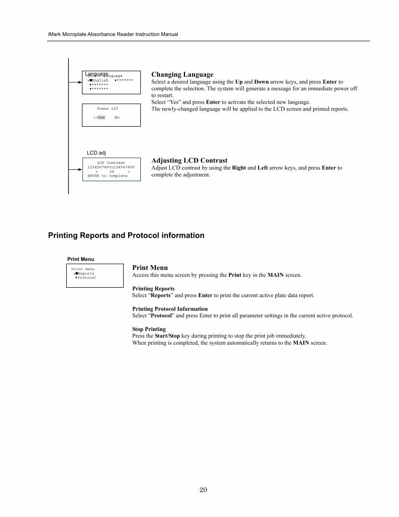
iMark Microplate Absorbance Reader Instruction Manual
21
Memory Recall Operation
01 200500 1400 02raquo210500 1700 03 200500 1800 darr04raquo200500 1900
01raquo200500 0900 02raquo200500 1000
Memory Recall raquoProtocol bullPlate Data
Protocol type menu
Data type menu
End Point
Kinetic
End Point
Kinetic
Memory Recall Menu
Select protocol type raquoEnd Point
bullKinetic bullCheckmark
Select Protocol 02 uarrraquo Protocol -2 Protocol -3 darr Protocol -4
Select Protocol 01 raquo Kinetic -1 GALT
Select data type raquoEnd Point
bullKinetic bullCheckmark
200501 0900
Checkmark
Checkmark program has been activated Press any key
Checkmark
Selecting Protocol Move the cursor to the position of the desired protocol and press Enter to complete the selection NOTE ldquordquo indicates the currently activated protocol and ldquordquo indicates a security locked protocol There is no protocol selection with ldquoCheckmarkrdquo When a protocol is selected the system will then automatically return to the MAIN screen
Changing Current Active Protocol Select ldquoProtocolrdquo in Memory Recall menu above and press Enter The Select Protocol type menu will appear on the screen Select a protocol using the Up and Down arrow keys Press Enter to complete the selection
Selecting Plate Data Move the cursor to the position of the desired plate data and press Enter to complete the selection NOTE ldquordquo indicates the currently activated plate data There is only one storage for ldquoCheckmarkrdquo data When plate data is selected the system automatically returns to the MAIN screen
Changing Current Active Plate Data Select ldquoPlate Datardquo using the Memory Recall button and press Enter The Data type menu will appear Use the Up and Down arrow keys to select a plate data type Press Enter to complete the selection
This menu screen can be accessed by pressing the Memory Recall key in the MAIN screen
iMark Microplate Absorbance Reader Instruction Manual
22
Editing the Kinetic Protocol
Select ldquoProtocolrdquo in the Edit Menu and press Enter The Kinetic Protocol menu will appear on the screen if the current active protocol type is Kinetic
Reading speed [Fast mode] Step mode
Speed
raquoReading Speed Inter Shaking Phmode
Kinetic Mode
Kinetic Protocol Menu
raquoMode Report Calc Kit name Mapping Assay
This menu screen can be accessed by selecting ldquoModerdquo in the Kinetic Protocol menu above
Number of Reading = 20 (2-30) Start Delay time = 25 sec(0-999)
Reading
Number of Reading = 2 Start Delay time = 25 sec(0-999)
Number of Readings and Start Delay Time Setting Press the Up or Down arrow key to change the number Enter the appropriate numbers with the numeral keys and press Enter to complete the field entry The system will return to the Kinetic Edit Menu If GALT is the current assay type the number of reading fields is fixed at 2 Press the StartStop key to set the Start Delay time enter a value and press Enter until the reading starts
1-gt2raquo 100 sec 2-gt3 100 sec 3-gt4 100 sec darr4-gt5 100 sec
Inter Use same interval between all reads
raquoYes No
Setting Reading Intervals The system prompts the operator to set a reading interval before each plate run Move the cursor to the desired selection ldquoYesrdquo or ldquoNordquo and press Enter The system generates the interval entry screen Move to the active entry field by pressing the Up and Down arrow keys and enter appropriate numbers using numeral keys Press Enter to complete all field entries The system will return to the Kinetic Mode menu
Photometric Dual Measurement405 nm Reference 655 nm
Ph mode Photometric Mode Setting When the ldquoPhotometricrdquo field is activated pressing the Right arrow key will switch the field entry ldquoSinglerdquo lt-gtrdquoDualrdquo Pressing the Up or Down arrow keys will move the cursor to the next entry field Pressing the Right arrow key when the wavelength field is activated will change the wavelength to the next available selection installed in the reader Press Enter to complete all field entries
Shaking parameters Before Every read Speed Mid Time 999 sec
Shaking Plate Shake Parameters When the ldquoBeforerdquo field is activated pressing the Right arrow key will change the field entry ldquoEveryrdquo-gtrdquo--rdquo-gtrdquoFirstrdquo-gt When the ldquoSpeedrdquo field is activated pressing the Right arrow key will change the field entry ldquoMidrdquo -gtrdquoHirdquo-gtrdquoLowrdquo-gt When the ldquoTimerdquo field is activated enter the time value for plate shaking period using the numeral keys Press Enter to complete all field entries
Selecting Reading Speed Use the Up or Down arrow keys to switch the selection Press Enter to complete the selection
Edit Menu raquoProtocol Labname Security bullSaveSTDC Filters bullPrinter Date set
This menu screen can be accessed by pressing the Edit key in the MAIN screen
iMark Microplate Absorbance Reader Instruction Manual
23
Kit name for 01 raquoGAP TEST IgGlaquo uarr [ABC]
Kit name
Calculation
Mapping
Assay
Assay type selection raquo[General KINETIC] GALT assay
Calculation Param CC Limit 0910
Calcrange 10 - 20
Select Mapping mode raquoManual mapping bullAutomatic mapping
raquo[Linregression] bullAbsorbance bullKINETIC Plots
Report
Plate Mapping See Plate Map setting procedure
Result = (R2 ndash R1)k k = 999999 R11st Reading R22nd Reading
If GALT
Setting the Kit Name Use the Up and Down arrow keys to select alphabet from ldquoArdquo to ldquoZrdquo and space Use the Number keys for numeric input Use the Right arrow key to move the cursor to the right Use the Left arrow key to return to the Protocol Menu screen Pressing ldquoFUNCrdquo key will change the character mode Upper case alphabet -gt Lower case alphabet -gt symbol The current character mode is indicated on the lower right corner of the LCD
Kinetic Protocol Menu
Selecting Kinetic Assay Type Move the cursor to the desired Assay type by pressing the Up or Down arrow keys Press Enter to complete the selection The item with mark ldquo[ ]rdquo is the currently selected item GALT assay Result = factor x (2nd Read ndash 1st Read)
Selecting Report Type Move the cursor to the desired report type by pressing the Up or Down arrow keys Pressing the Right arrow key will select or deselect the item Press Enter to complete the selection Note When GALT assay is selected ldquoGALT reportrdquo shall be the only one option on this screen
raquoMode bullReport bullCalc bullKit name bullMapping bullAssay
Calculation Parameter Setting When the ldquoCC Limitrdquo field is activated pressing the numeral key will enter the desired numbers Press Enter to complete all field entries If the GALT Reports is activated pressing the numeral keys will enter the desired numbers Press Enter to complete all field entries
iMark Microplate Absorbance Reader Instruction Manual
24
Checkmark Value Setting (Administrator only)
raquoSerial Report bullLinearity ref bullMaxCV bullFilter Check ref
Checkmark Protocol Menu
raquoSerial 0000 Reptype Simple
405nm S10158 Linearity S20309 reference S31401 S42109
MaxCV raquoS115 Linearity S205 reference S302 S402
Filter max min 4051875 0329 4501167 0954 darr 4920596 0103
Serial Report
Linearity reference
Max CV
Filter check reference
Filter max min uarr 5401875 0329 6201167 0954 6900596 0103
Setting the Serial Number and Report Type Pressing the Up and Down arrow keys will move the cursor and change the field entry When ldquoSerial rdquo field is active enter the serial number that will be shown in the data sheet of the Checkmark plate using the numeral keys When the ldquoRep typerdquo field is active pressing the Right arrow key will switch the report type between ldquoSimplerdquo and ldquoFullrdquo
Setting the Linearity Reference Value Pressing the Up or Down arrow keys will move the field entry from S1 to S4 Pressing the Right arrow key will change the wavelength 405 nm-gt450 nm-gt492 nm-gt540 nm-gt620 nm-gt690 nm Use the numeral keys for the reference value setting Pressing Enter will complete all field entries at all wavelength
Max CV setting Pressing the Up or Down arrow keys will move the field entry from S1 to S4 Use the numeral keys for the Max CV setting Press Enter to complete all field entries
Setting the Filter Check Reference Value Initial screen shows the reference entries for 405 nm to 492 nm and pressing the Down arrow key at the bottom of the screen entries will scroll to the next page for 540 nm to 690 nm Pressing the Up Down and Right arrow keys will move the field entry Use the numeral keys for the filter check reference value setting Press Enter to complete all field entries
Select ldquoProtocolrdquo in the Edit Menu and press Enter The Checkmark Protocol Menu will appear on the screen if the current active protocol type is Checkmark mode
Edit Menu raquoProtocol bullLabname bullSecurity bullSaveSTDC bullFilters bullPrinter bullDate set
This menu screen can be accessed by pressing the Edit key in the MAIN screen
iMark Microplate Absorbance Reader Instruction Manual
25
Editing End Point Protocol
Upper Limit= 2000 Lower Limit= 0000 input range 0ndash3500 Upper gt Lower
Standard menu raquoSTD information
bullCurvefit bullRecall STD Curve
raquoCutoff bullMode bullReport bullMapping bullLimit bullKit name bullSTDs
Cutoff
See Plate Map setting procedure
See Standard setting procedure
See Mode setting procedure
raquo[Not use] bullRatio bullConstant bullContrl bullFormula
raquoSet photo mode bullSet shaking bullSet read mode
Select mapping mode raquoManual mapping bullAutomatic mapping
Mapping
Mode
Report
STDs
Limit
Kit name for 01 raquoGAP TEST IgGlaquo uarr [ABC]
Kit name See Kit name setting in Editing Kinetic Protocol
See Cutoff setting procedure
Select ldquoProtocolrdquo in Edit Menu screen above and press Enter The End point Protocol Menu will appear on the screen if the current active protocol type is End point mode
End Point Protocol Menu
raquo[Raw] bullMtx bullCnc bullAbs bullCut bullDif bullLim bullCrv
If ldquoDifrdquo selected
[Raw] bullMtx bullCncbullAbs bullCut [Dif] bullLim bullCrv raquorow odd-even
Seting the Report Type Use the Up and Down Arrow key to move the cursor and press the Right Arrow key to select or deselect the report type Selected report type is marked as ldquo[ ]rdquo Press Enter to complete the selection
Setting the Limit Value Use the Up and Down Arrow key to move the cursor and enter the OD value using the numeral keys The OD value range is 0000 - 3500 Press Enter to complete the selection
Edit Menu raquoProtocol bullLabname bullSecurity bullSaveSTDC bullFilters bullPrinter bullDate set
This menu screen can be accessed by pressing the Edit key in the MAIN screen
iMark Microplate Absorbance Reader Instruction Manual
26
Cutoff Setting Procedure
Cutoff Setting Menu This menu is entered by choosing Cutoff in the End Point Protocol Menu It is used to set the cutoff type The cutoff type marked with ldquo[ ]rdquo is the current selection The Up and Down arrow keys move the cursor to the desired item in the menu list When the desired parameters have been selected press Enter twice to accept the selection and to continue to the next screen Not use means that the reader does not generate the cutoff report Four types of cutoff are supported
1 Cutoff Constant 2 Cutoff Control 3 Cutoff Formula 4 Cutoff Ratio
a Cutoff Constant
Selection of SingleRanged Cutoff Constant This menu selects Single or Ranged cutoff type The cutoff type marked with ldquo[ ]rdquo is the current selection The Enter key seals the selection and resumes to the next setting screen
Single Cutoff Constant The Numerical keys and the Decimal point key are used to enter the positive and gray zone values The Right arrow key is used to select the unit The Up and Down arrow keys move the cursor to the desired parameter of the single cutoff The Enter key sets all values and selection of the cutoff constant and returns the user to the previous screen Ranged Cutoff Constant The Numerical keys and the Decimal point key are used to enter the positive and negative values The Right arrow key is used to select the unit The Up and Down arrow key moves the cursor to the desired ranged cutoff parameters The Enter key sets all values and selection of the cutoff constant and returns to the previous screen NOTE Two available Cutoff constants are ldquoAbsorbancerdquo and ldquoConcentrationrdquo If Abs is chosen the Absorbance cutoff will be done with the cutoff constant parameters defined and the absorbance report is generated For other units defined in the curve fit setting the Concentration value using the curve fit and then cutoff is done with the cutoff constant parameters defined and the concentration value of each well It is necessary to set the curve fit parameters
raquoNot usex bullRatio [Const] bullContrl bullFormula
raquoPositive gt= 9999 Gray zone 50 Unit moll
raquoPositive gt= 9999 Negative lt 1999 NegativeltPositive Unit moll
raquoRanged cutoff [Single cutoff]
Single cutoff
Ranged
iMark Microplate Absorbance Reader Instruction Manual
27
b Cutoff Control
Selection of SingleRanged Cutoff Control This menu screen selects Single or Ranged cutoff type The cutoff type marked with ldquo[ ]rdquo is the current selection The Enter key seals the selection and resumes to the next setting screen
Single Cutoff Control The Numerical keys are used to enter the gray zone value The unit is fixed to Abs The Enter key sets the value of the cutoff control and returns to the previous screen Ranged Cutoff Control There is no parameter to set for the ranged cutoff control The Enter key returns to the previous screen NOTE CNx is the mean absorbance value of Negative control wells and CPx is the mean absorbance value of Positive control wells These wells are defined in the plate map setting The cutoff is done with the Positive and Negative value to the absorbance value of each well
c Cutoff Formula
Selection of Formula This menu screen selects a formula for cutoff calculation The formula marked with ldquo[ ]rdquo is the current selection The Up and Down arrow keys move the cursor to the desired formula type The movement of the cursor follows the scroll of this screen The Enter key marks the selection and advances the user to the next setting screen The supported formula types are
1 k CNx 2 k CPx 3 k COx 4 CNx k 5 CPx k 6 COx k 7 k + CNx 8 k + CPx 9 k + COx 10 kCNx + CPx 11 ( CNx + CPx ) k 12 k1CNx + k2CPx
Coefficient for Cutoff Formula 1 to 11 The Numerical keys and the Decimal point key are used to enter the coefficient k and gray zone values The Up and Down arrow key moves the cursor to the desired parameter of the cutoff formula The Enter key sets all values of the cutoff formula and returns to the previous screen
Positive gt= CNx Gray zone 50 Unit Abs
Positive gt= CPx Negative lt CNx Unit Abs
Enter key to accept
raquoRanged cutoff [Single cutoff]
Single cutoff
Ranged
Input coefficient k = 001 (001-10) Gray zone 50(0-99)
k CNx k CPx k COx CNx k CPx k COx k k + CNx k + CPx k + COx k CNx + CPx (CNx + CPx) k
uarr raquoCNx k bullCPx k bullCOx k darr bullk + CNx
Select formula raquo[kCNx ] bullkCPx darr bullkCOx
uarr raquok + CPx bullk + COx bullkCNx + CPx darr bull(CNx + CPx) k
uarr raquok1CNx + k2CPx
Page-1
Page-2
Page-3
Page-4
iMark Microplate Absorbance Reader Instruction Manual
28
Coefficient for Cutoff Formula 12 The Numerical keys and the Decimal point key are used to enter the coefficient k1 and k2 and gray zone values The Up and Down arrow key moves the cursor to the desired cutoff formula The Enter key sets the all values of the cutoff formula and returns to the previous screen NOTE CNx is the mean absorbance value of Negative control wells CPx is the mean absorbance value of Positive control wells and COx is the mean absorbance value of Cutoff control wells These wells are defined on the plate map setting The cutoff value is calculated using the defined formula with the defined values and coefficients
d Cutoff Ratio
Ratio to Calibrator In this screen there are three items for setting the ratio to calibrator The Up and Down arrow key moves the cursor to the desired item in the menu list The Enter key seals the selection and resumes to the next setting screen
Concentration of Calibrator The Numerical keys and the Decimal point key are used to enter the calibrator concentration value The Enter key sets the value and returns to the previous screen Unit of Calibrator Seventeen standard units are supported The unit marked with ldquo[ ]rdquo is the current selection The setting procedure is the same as the unit selection of Standards Cutoff Value Setting This menu screen selects Single or Ranged cutoff type The cutoff type marked with ldquo[ ]rdquo is the current selection The Enter key marks the selection and continues to the next setting screen Single Cutoff Control The Numerical keys are used to enter the Positive cutoff concentration value and gray zone value The Enter key sets these cutoff ratio values and returns to the previous screen Ranged Cutoff Control The Numerical keys are used to input the Positive and the Negative cutoff concentration values The Enter key sets these cutoff ratios and returns to the previous screen NOTE The calibrator concentration value is used to convert the absorbance value of each well into a concentration value The ratio of ConcentrationAbsorbance of Calibrator well is applied to the conversion The cutoff uses defined Positive and Negative values to the converted concentration value of each well
Input coefficient k1 = 001 (001-10) k2 = 100 (001-10) Gray zone 50(0-99)
k1 CNx + k2 CPx
Ratio to Calibrator raquoConcentration bullUnit bullCutoff value
Concentration 9999 unit moll
uarrraquo 01 ugdl 02 ngml 03[ pgml] darr 04 pmml
raquoPositive gt= 9999 Gray zone 50
Unit moll
raquoPositive gt= 9999 Negative lt 9999 NegativeltPositive
Unit moll
raquoRanged cutoff [Single cutoff]
Concentration
Unit
Cutoff value
Single cutoff
Ranged cutoff
iMark Microplate Absorbance Reader Instruction Manual
29
Standard Setting Procedure
Standard Curve Setting Menu This menu screen is entered by choosing STDs in the End Point Protocol Menu screen It is used to set the concentration data and the curve fit type for a standard curve or to recall a memorized standard curve The Up and Down arrow key moves the cursor to the desired item in the menu list The Enter key seals the selection and continues to the next setting screen
a STD Information Setting
STD Information In this screen there are three items for setting the concentration data of standards The Up and Down arrow keys move the cursor to the desired item in the menu list The Enter key seals the selection and continues to the next setting screen
Number of Standards The Numerical keys are used to enter the number of standards ldquo0rdquo means that the curve fit report is not used The Enter key sets the number and returns to the previous screen The maximum number of standards is 12 Concentration The Numerical keys and the Decimal point key are used to enter the concentration values of standards The Up and Down arrow keys move the cursor to the desired position The movement of the cursor also follows the scroll of this screen The Enter key sets all values of the concentration of standards and returns to the previous screen Unit Seventeen units are supported The unit marked with ldquo[ ]rdquo is the current selection The Up and Down arrow keys move the cursor to the desired unit type The movement of the cursor also follows the scroll of this screen Press Enter twice to select the unit type and to return to the previous screen The supported types of unit are
1 moll 11 pgml 2 m moll 12 Uml 3 u moll 13 IUml 4 n moll 14 uIUml 5 p moll 15 mIUml 6 mgl 16 EU 7 ngl 17 Arbit 8 pgl 9 ugdl 10 ngml
STD information raquoNumber of STD bullConcentration bullUnit
STD 1 0512 STD 2 1012 STD 3 1512 darr STD 4 2053
Standard menu raquoSTD information bullCurve fit bullRecall STD curve
Concentration
Number of STD
Number of STD = 05 (0 2ndash12)
uarrraquo 01 ugdl 02 ngml 03[ pgml] darr 04 pmml
Unit
iMark Microplate Absorbance Reader Instruction Manual
30
b Curve Fit Setting
Curve Fit In this screen there are two choices to set the curve fit The Up and Down arrow keys move the cursor to the desired item in the menu list The Enter key seals the selection and resumes to the next setting screen
Curve Fit Type 10 types of curve fit are supported as below The curve fit type marked with ldquo[ ]rdquo is the current selection The Up and Down arrow key moves the cursor to the desired curve fit type The movement of the cursor follows the scroll of this screen Press Enter twice to select the unit type and to return to the previous screen The supported curve fit types are
1 5P Logistic Rodbard 2 4P Logistic Rodbard 3 5P Logistic Cook-Wilkenson 4 4P Logistic Cook-Wilkenson 5 5P Exponential 6 Sigmoid Logistic 7 Linear regression 8 Quadratic regression 9 Cubic 10 Point To Point regression
Graph Axis Four types of graph are supported The curve fit type marked with ldquo[ ]rdquo is the current selection The Up and Down arrow keys move the cursor to the desired graph type Press Enter twice to select the unit type and to return to the previous screen The supported graph types are
1 Log - Log 2 Log - Linear 3 Linear - Log 4 Linear - Linear
uarr 5p logisticRodb raquo 4p logisticRodb [5p logisticCook] darr 4p logisticCook
raquo X-Log Y-Log [X-Log Y-Lin] X-Lin Y-Log X-Lin Y-Lin
Curve fit type
Graph axis
Curve fit setting raquoCurve fit type bullGraph axis
iMark Microplate Absorbance Reader Instruction Manual
31
c Recall STD Curve Setting
Recall Setting of Standard Curve In this screen there are two items for setting the Recall STD curve as below The Up and Down arrow keys move the cursor to the desired item in the menu list
1 Recall setting (YesNo) 2 Selecting the storage number of standard curves (1 -gt 5)
Recall Setting Move the cursor to the desired position using the Up Down or Right arrow keys Enter key accepts the setting and returns the user to the standard menu screen
Yes Recalling of the standard curve is active No Recalling of the standard curve is inactive
Storage Number Selection Five memories are selectable The vacant memory (marked with asterisks on the date and time field) is also selectable It is necessary to save a standard curve before using its protocol Move the cursor to the desired position using the Up and Down keys This setting screen consists of two parts The Right arrow key is used to switch the indication field between the date and time to the standard curve name Move the cursor to the desired position using the Up and Down keys The Enter key accepts the storage number and returns to the standard menu screen NOTE If the recall of standard curve is active (the recall setting is ldquoYesrdquo) the standard information setting and the curve fit setting will be invalidated and their setting screens will not open
Recall STD curve raquoRecall setting bullSelect STD curve
Recall setting raquoYes No
Recall setting
Select STD Curve raquo1160304 1125
2 darr 3150304 1030
Select STD Curve uarrraquo4
5
Select STD Curve raquo1 STD Curve 1
2 STD Curve 2 darr 3 STD Curve 3
Select STD Curve uarrraquo4 STD Curve 4
5 STD Curve 5
Select STD curve
Right arrow key
iMark Microplate Absorbance Reader Instruction Manual
32
Mode Setting Procedure
Mode Setting Menu This menu screen is entered by choosing the Mode in the End Point Protocol Menu screen or the Kinetic Protocol Menu screen It is used to set the plate reading conditions The Up and Down arrow keys move the cursor to the desired item in the menu list The Enter key seals the selection and resumes to the next setting screen
a Set Photo Mode
Photo Mode In this screen the user chooses Single or Dual wavelength measurement and assigns the measurement and reference (for dual wavelength measurement) filters The assignment of the reference filter appears for dual wavelength measurement The Up and Down arrow keys move the cursor to the desired parameter The Right arrow key chooses SingleDual wavelength measurement and selects the installed filter on the Filters of Edit Menu screen The Enter key seals the selection and returns to the previous screen
b Set Shaking
Shaking In this screen the user selectsdeselects shaking function sets the shaking strength and enters the shaking time A shaking time of 0s indicates no shaking The maximum shaking time is 999 seconds The Up and Down arrow key moves the cursor to the desired parameters The Right arrow key toggles between YesNo (SelectDeselect) shaking or selects strength LowMiddleHigh The Numerical keys are used to enter the shaking time The Enter key seals the selection and returns the user to the previous screen
c Set Read Mode
Read Mode In this screen the user chooses Fast or Step reading and also chooses Normal or Evaluation mode The ldquo[ ]rdquoindicates the current selection The Up and Down arrow key moves the cursor to the desired parameters The Right arrow key chooses FastStep speed or chooses NormalEval mode The Enter key seals the selection and returns to the previous screen The followings are the description of each read mode parameter Reading speed
Fast reading 6 secsingle wavelength reading 10 secdual wavelength reading
Step reading 15 secsingle wavelength reading 30 secdual wavelength reading
Reading mode
Normal mode Plate reading once Evaluation mode Four plate readings per one of measurement are performed and
the average data of their plate readings is generated as a plate data
Photometric Dual Measurement400 nm Reference 655 nm
Set Shake parameters ShakeYes SpeedMid Time 199sec(0-999)
raquoReading speed [Fast ] Step bullRead mode [Normal] Eval
raquoSet Photo mode bullSet shaking bullSet read mode
Photometric Single Measurement400 nm
iMark Microplate Absorbance Reader Instruction Manual
33
Plate Map Setting Procedure
Select Mapping Mode Menu This menu screen is entered by choosing Mapping in the End Point Protocol Menu screen or the Kinetic Protocol Menu screen It is used to map the plate format The Up and Down arrow keys move the cursor next to the desired item of menu list The Enter key seals the selection and changes this screen to the next setting screen
a Manual Mapping
Manual Mapping In this screen the user can set the plate format manually Ten well types can be set Well types The supported well types are
Well type Indication on LCD
1 Blank B 2 Sample X00hellipX99 3 Standard S01hellipS99 4 In-kit Control Positive Control CP0hellipCP9 5 Weak Positive Control CW0hellipCW9 6 Negative Control CN0hellipCN9 7 Cutoff Control CO0hellipCO9 8 Calibrator CL0hellipCL9 9 QC Control QC0hellipQC9 10 Empty well -
The key assignments of well type are ldquo0EMPrdquo Empty well ldquo5QCrdquo Quality Control well ldquo1SMPrdquo Sample well ldquo6CALrdquo Calibrator well ldquo2BLKrdquo Blank well ldquo7CPrdquo Positive Control well ldquo3STDrdquo Standard well ldquo8CNrdquo Negative Control well ldquo4COrdquo Cutoff Control well ldquo9CWrdquo Weak Positive Control well
Two Edit Modes in Plate Mapping There are two editing modes for well type input mode and for well number input The current input mode is displayed at the upper left corner of the screen When using the well type input mode the mode sign is ldquo[F]rdquo When using the well number input mode the mode sign is ldquoNrdquo The cursor that encloses the editing position of well has two types of enclosures depending on the mode For example ldquo[S01]rdquo accepts the well type keys that be assigned to the numerical keys and ldquoS01rdquo accepts the numerical input The mode is easily changed with the Decimal point key Key Functions The Up Down Right and Left arrow keys move the cursor to the desired well The movement of the cursor follows the scroll of this screen The Left arrow key will return the screen to the preceding screen or the select Mapping mode Menu only if the cursor is on column 1 At this time the selection screen appears (see the left figure) The Decimal point key changes the input mode The Numerical keys have two functions one to input the number and another to select a well type The Enter key checks the consistency between the edited plate map and other parameters memorizes the plate map into the protocol and changes this screen back to the preceding screen If it finds any inconsistency a warning message will appear on the screen
Select Mapping mode raquoManual mapping bullAutomatic mapping
N 1 2 3 4 A B CN1 S01 S01 B B CN1 S02 S02 C B CN2 S03 S03 [F] 5 6 7 8 A X11 X12 X13 X14 B X21 X22 X23 X24 C X31 X32 X33[X34]
Discard change 1Yes 2No Press 1 or 2 key
iMark Microplate Absorbance Reader Instruction Manual
34
Acceptable Number Ranges for each well type 1 Blank and Empty wells do not use numbers 2 Sample and Standard wells 00 - 99 3 Standard wells 01 - 99 4 Control and Calibrator wells 0 - 9
b Automatic Mapping
Automatic Mapping The user can input the number of each well type in this screen These defined numbers are used to set a plate map automatically Well type Nine well types are available
1 BLK Blank (0-gt10) 2 CN Control CN (0-gt9) 3 CW Control CW (0-gt9) 4 CP Control CP (0-gt9) 5 CO Control CO (0-gt9) 6 QC Control QC (0-gt9) 7 CAL Calibrator (0-gt9) 8 SMP Sample (0-gt96) 9 REP Replicate well (1-gt4)
It is possible to define the number of blanks samples calibrators and controls But the number of Standards is not included because standards are defined at the Standard Setting Menu The number of replicate wells is also included It is used for replicating each well type individually Key Functions The Up Down Right and Left arrow keys are used to move the cursor to the next position The Numerical keys are used to input the mapping parameters The Enter key accepts the mapping parameters and sets a plate map automatically using these parameters During the execution of the plate mapping the Plate auto-mapping completed message appears on the screen After that the user returns automatically to the previous Protocol Menu screen If the Left arrow key is pressed at the left end position of the cursor the left figure will appear on the screen If the user chooses Yes the system will return to the previous Protocol Menu screen If the user chooses No the system will stay in this setting screen Assigning Order and Direction of plate mapping Assigning Order The order of blanks standards samples calibrators and controls are fixed as follows Numbering for standards samples calibrators and controls is started at 1
1 Blank 2 Standard 1 -gt12 ---- NOTE 3 Control CN 1-gt9 4 Control CW 1-gt9 5 Control CP 1-gt9 6 Control CO 1-gt9 7 Control QC 1-gt9 8 Calibrator 1-gt9 9 Sample 1-gt96 10 Empty well NOTE If ldquoCutoff Controlrdquo ldquoValue by Formulardquo or ldquoRatio to Calibratorrdquo is
selected for the Cutoff plate mapping skips arranging the standards Assigning Direction The placing direction of the mapping is limited to the column direction as below
Column direction A1 -gt H1 A2 -gt H2 ----- A12 -gt H12
Discard change 1Yes 2No Press 1 or 2 key
Automatic mapping BLK= 1 CP = 1 CAL= 0 CN = 1 CO = 0 SMP=93 CW = 0 QC = 0 REP= 1
Plate auto-mapping completed
iMark Microplate Absorbance Reader Instruction Manual
35
Warning and Error of Automatic Mapping Warning screen If the total number of wells mapped exceeds 96 wells a warning message in the left figure appears on the screen The calculation of the total number of mapping wells is as follows
(Blanks+Standards+CNs+CWs+CPs+COs+QCs+Calibrators+Sample)Replicates The plate mapping is executed normally and the exceeded part is invalidated Error screen If one or more mapping parameters are over the input range an error message in the left figure will appear on the screen On the third line of the LCD the name of the parameter which is out of range and its input range will appear
Example ldquoBLK 0 ndash 10rdquo In case there is more than one error the first parameter of errors is indicated By pressing any key the user returns to the automatic mapping screen Example of automatic mapping An example of automatic mapping is as below 1 Conditions of each parameter
Blank = 1 Standard = 8 Control CN = 2 CW = 0 CP = 2 CO = 0 QC = 0 Calibrator = 1 Sample = 32 Replicate number = 2
2 Plate mapping data
1 2 3 4 5 6 7 8 9 10 11 12 A B C D E F G H
B B S1 S1 S2 S2 S3 S3
S4 S4 S5 S5 S6 S6 S7 S7
S8 S8 CN1 CN1 CN2 CN2 CP1 CP1
CP2 CP2 CL1 CL1 X1 X1 X2 X2
X3 X3 X4 X4 X5 X5 X6 X6
X7 X7 X8 X8 X9 X9 X10 X10
X11 X11 X12 X12 X13 X13 X14 X14
X15 X15 X16 X16 X17 X17 X18 X18
X19 X19 X20 X20 X21 X21 X22 X22
X23 X23 X24 X24 X25 X25 X26 X26
X27 X27 X28 X28 X29 X29 X30 X30
X31 X31 X32 X32 E E E E
Warning The total Of mapped wells has Exceeded 96 Press any key
Entered value is Out of range BLK 0 ndash 10 Press any key
iMark Microplate Absorbance Reader Instruction Manual
36
Instrument Maintenance
Caution Electrical shock hazard Always disconnect the instrument from the AC power source before opening the service compartment
Caution The lamp and the lamp cover may be very hot Use caution and allow the lamp to cool
before attempting service
Installing Interference Filters 1 With the power off open the rear cover of the instrument by pressing the
release latch located on the top left portion of the cover 2 Locate the filter wheel on the left side of the instrument Note that the
filter wheel has eight filter positions 3 Rotate the filter wheel to the desired filter Grasp the top of filter frame
and pull up to remove the filter 4 Insert the new filter into the desired filter position 5 Ensure that the new filter is added to the filter list as follows Main
menu-gtEdit-gtFilters
Changing the Lamp 1 With the power off open the rear cover of the instrument by pressing the
release latch located on the top left portion of the cover 2 Remove the two screws on the black plastic cover and carefully remove
the plastic cover 3 Remove the screw on the metal cover Lift the cover up and away from
the instrument This will allow the lamp to be pulled free from the lamp housing
4 Holding the ceramic base in one hand and the lamp housing in the other carefully pull the lamp free of the base
5 Carefully insert the new lamp firmly in the ceramic base Apply even pressure when inserting the lamp so that the bulb dose not become misaligned in the reflector housing Be extremely careful not to touch the front glass of the lamp during installation
6 Position the new lamp into the housing so that the plastic guides hold the flange of the lamp
7 Carefully place the metal cover over the lamp Tighten the screw 8 Replace the plastic cover and tighten the screws 9 Close the rear cover
iMark Microplate Absorbance Reader Instruction Manual
37
Troubleshooting and Error Messages
The iMark Microplate Reader constantly monitors several functions and displays appropriate messages on the LCD as errors are encountered
Error Recommendation
LCD appears blank on power up
a Power is not turned on The AC outlet is non-functional
b Unit is not plugged into AC outlet or power code is not attached to the instrument
Check power cord connections at outlet and on the rear panel of the instrument
1
c The AC outlet is non-functional Check circuit breakers or fuses
Instrument displays ldquoLight bulb errorrdquo message indicating that the bulb is burned out
Check whether lamp is emitting light
a Lamp is not emitting light Replace the lamp as described in x
2
b Lamp is emitting light Check the alignment of the lamp in the housing Align or replace the lamp if necessary
Printer will not print on command
3
a Printer paper is not installed properly Verify that the paper is properly installed Refer to x for details
Plate carriage jams during reading and ldquoPlate carrier errorrdquo is displayed
a Plate is not seated in carriage properly Press the STOP button immediately Position the plate carefully in the carriage making certain that it is properly seated
4
b Plate height is exceeding 16mm Use Microplate which is less than 16mm in height
5 LCD displays ldquoFilter missingrdquo Install a filter in the empty position Select the installed filter by pressing Edit key
6 LCD displays ldquoFilter disk jammedrdquo indicating that the filter wheel is not turning freely
Turn off the instrument and inspect the filter wheel Turn by hand to verify that the wheel is moving freely Make sure all the filters are properly installed and firmly seated Contact your Bio-Rad representative if the filter wheel is jammed or if the problem persists
7 LCD displays ldquoFilter not installedrdquo Enter the Edit Menu by pressing Edit key and set up the filters
iMark Microplate Absorbance Reader Instruction Manual
38
Wells have color but absorbance values seem low
a Incorrect filter used for measurement andor reference wavelength
Check wavelength used in analysis Read plate in single wavelength mode at all wavelength to verify that the proper filter was used The measurement wavelength should produce the highest absorbance
b The best measurement wavelength filter for the substrate in use has not been installed in the filter wheel
Check references for the substrate you are using or determine the best measurement wavelength by analyzing the substrate product on a scanning spectrophotometer Custom filters are available from 400 to 750 nm
8
c The filters have been switched in the wheel Check that the filters are installed in the correct position
9 ldquoPrinter errorrdquo displayed Check for paper jam Install the printer paper correctly
10 ldquoBattery errorrdquo displayed The internal battery is almost dead Contact your local Bio-Rad office
11 The following messages are displayed ldquoMemory errorrdquo ldquoCalendar errorrdquo ldquoLCD hardware errorrdquo ldquoPrinter errorrdquo ldquoLight level errorrdquo ldquoDA conversion errorrdquo ldquoAD conversion errorrdquo ldquoEEPROM errorrdquo ldquoUSB errorrdquo
Contact your local Bio-Rad office if these problems persist
iMark Microplate Absorbance Reader Instruction Manual
39
Instrument Specifications Computer interface USB 20
Plate shaking 3 speeds (low mid high) Programmable time period 0 - 999 seconds
Data storage The most recent 10 data plates for end-point most recent 2 data plates of 30 readings for kinetic readings protocol data and calendarclock function shall be kept in memory by a lithium battery even when the power is off Average lifetime of the battery shall be 5 years
Warm-up time 3 minutes
Photometric Methods Single and dual wavelength
Photo detectors 8 silicon photodiodes for measurement and 1 silicon photodiode for reference
Light source Tungsten halogen lamp 20W with 3000 hours average lifetime
Spectral range 400 nm to 750 nm
Interference filters Wavelength tolerance plusmn30 nm Band width 10 nm typically
Filter capacity 8 filters
Reading speed Fast Reading 6 sec with single wavelength reading 10 sec with dual wavelength reading
Step Reading 15 sec with single wavelength reading 25 sec with dual wavelength reading
These times are minimum interval times between repetitive reads using onboard KINETIC protocol
Indication range 0000 to 35 OD
Resolution 0001 OD
Accuracy plusmn10 or 0010 from 0 to 30 OD at 490 nm
Linearity plusmn10 from 0 to 20 OD plusmn20 from 0 to 30 OD
Reproducibility 10 or 0005 OD from 0 to 20 OD 15 from 20 to 30 OD
Inter-channel variability 15 or 0005 OD from 0 to 30 OD
Stability and Drift 0010 OD at OD=1 with single wavelength reading
Built-in Printer Thermal printer Paper width 80mm
Line Voltage Universal input 100 - 240 VAC 5060Hz
Power consumption (max) 100 VA max
Dimensions (W x D x H 346 mm x 377 mm x 164 m mm
Weight 55 kg
Operating Environment 15ordmC - 40ordmC up to 90 relative humidity without condensation
Storage Temperature 10ordmC - 50ordmC up to 90 relative humidity without condensation
Life ScienceGroup
07-0816 0108 Sig 120710013301i Rev A USEG
Bio-RadLaboratories Inc
Web site wwwbio-radcom USA 800 4BIORAD Australia 61 02 9914 2800 Austria 01 877 89 01 Belgium 09 385 55 11 Brazil 55 21 3237 9400 Canada 905 364 3435 China 86 21 6426 0808 Czech Republic 420 241 430 532 Denmark 44 52 10 00 Finland 09 804 22 00 France 01 47 95 69 65Germany 089 318 84 0 Greece 30 210 777 4396 Hong Kong 852 2789 3300 Hungary 36 1 455 8800 India 91 124 4029300 Israel 03 963 6050 Italy 39 02 216091 Japan 03 6361 7000 Korea 82 2 3473 4460 Mexico 52 555 488 7670 The Netherlands 0318 540666 New Zealand 0508 805 500 Norway 23 38 41 30 Poland 48 22 331 99 99 Portugal 351 21 472 7700 Russia 7 495 721 14 04 Singapore 65 6415 3188 South Africa 27 861 246 723 Spain 34 91 590 5200 Sweden 08 555 12700 Switzerland 061 717 95 55 Taiwan 886 2 2578 7189 United Kingdom 020 8328 2000
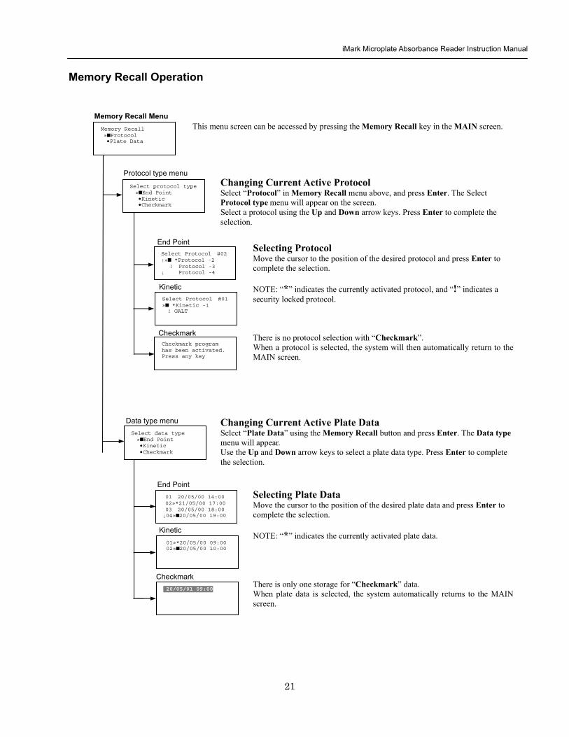
iMark Microplate Absorbance Reader Instruction Manual
22
Editing the Kinetic Protocol
Select ldquoProtocolrdquo in the Edit Menu and press Enter The Kinetic Protocol menu will appear on the screen if the current active protocol type is Kinetic
Reading speed [Fast mode] Step mode
Speed
raquoReading Speed Inter Shaking Phmode
Kinetic Mode
Kinetic Protocol Menu
raquoMode Report Calc Kit name Mapping Assay
This menu screen can be accessed by selecting ldquoModerdquo in the Kinetic Protocol menu above
Number of Reading = 20 (2-30) Start Delay time = 25 sec(0-999)
Reading
Number of Reading = 2 Start Delay time = 25 sec(0-999)
Number of Readings and Start Delay Time Setting Press the Up or Down arrow key to change the number Enter the appropriate numbers with the numeral keys and press Enter to complete the field entry The system will return to the Kinetic Edit Menu If GALT is the current assay type the number of reading fields is fixed at 2 Press the StartStop key to set the Start Delay time enter a value and press Enter until the reading starts
1-gt2raquo 100 sec 2-gt3 100 sec 3-gt4 100 sec darr4-gt5 100 sec
Inter Use same interval between all reads
raquoYes No
Setting Reading Intervals The system prompts the operator to set a reading interval before each plate run Move the cursor to the desired selection ldquoYesrdquo or ldquoNordquo and press Enter The system generates the interval entry screen Move to the active entry field by pressing the Up and Down arrow keys and enter appropriate numbers using numeral keys Press Enter to complete all field entries The system will return to the Kinetic Mode menu
Photometric Dual Measurement405 nm Reference 655 nm
Ph mode Photometric Mode Setting When the ldquoPhotometricrdquo field is activated pressing the Right arrow key will switch the field entry ldquoSinglerdquo lt-gtrdquoDualrdquo Pressing the Up or Down arrow keys will move the cursor to the next entry field Pressing the Right arrow key when the wavelength field is activated will change the wavelength to the next available selection installed in the reader Press Enter to complete all field entries
Shaking parameters Before Every read Speed Mid Time 999 sec
Shaking Plate Shake Parameters When the ldquoBeforerdquo field is activated pressing the Right arrow key will change the field entry ldquoEveryrdquo-gtrdquo--rdquo-gtrdquoFirstrdquo-gt When the ldquoSpeedrdquo field is activated pressing the Right arrow key will change the field entry ldquoMidrdquo -gtrdquoHirdquo-gtrdquoLowrdquo-gt When the ldquoTimerdquo field is activated enter the time value for plate shaking period using the numeral keys Press Enter to complete all field entries
Selecting Reading Speed Use the Up or Down arrow keys to switch the selection Press Enter to complete the selection
Edit Menu raquoProtocol Labname Security bullSaveSTDC Filters bullPrinter Date set
This menu screen can be accessed by pressing the Edit key in the MAIN screen
iMark Microplate Absorbance Reader Instruction Manual
23
Kit name for 01 raquoGAP TEST IgGlaquo uarr [ABC]
Kit name
Calculation
Mapping
Assay
Assay type selection raquo[General KINETIC] GALT assay
Calculation Param CC Limit 0910
Calcrange 10 - 20
Select Mapping mode raquoManual mapping bullAutomatic mapping
raquo[Linregression] bullAbsorbance bullKINETIC Plots
Report
Plate Mapping See Plate Map setting procedure
Result = (R2 ndash R1)k k = 999999 R11st Reading R22nd Reading
If GALT
Setting the Kit Name Use the Up and Down arrow keys to select alphabet from ldquoArdquo to ldquoZrdquo and space Use the Number keys for numeric input Use the Right arrow key to move the cursor to the right Use the Left arrow key to return to the Protocol Menu screen Pressing ldquoFUNCrdquo key will change the character mode Upper case alphabet -gt Lower case alphabet -gt symbol The current character mode is indicated on the lower right corner of the LCD
Kinetic Protocol Menu
Selecting Kinetic Assay Type Move the cursor to the desired Assay type by pressing the Up or Down arrow keys Press Enter to complete the selection The item with mark ldquo[ ]rdquo is the currently selected item GALT assay Result = factor x (2nd Read ndash 1st Read)
Selecting Report Type Move the cursor to the desired report type by pressing the Up or Down arrow keys Pressing the Right arrow key will select or deselect the item Press Enter to complete the selection Note When GALT assay is selected ldquoGALT reportrdquo shall be the only one option on this screen
raquoMode bullReport bullCalc bullKit name bullMapping bullAssay
Calculation Parameter Setting When the ldquoCC Limitrdquo field is activated pressing the numeral key will enter the desired numbers Press Enter to complete all field entries If the GALT Reports is activated pressing the numeral keys will enter the desired numbers Press Enter to complete all field entries
iMark Microplate Absorbance Reader Instruction Manual
24
Checkmark Value Setting (Administrator only)
raquoSerial Report bullLinearity ref bullMaxCV bullFilter Check ref
Checkmark Protocol Menu
raquoSerial 0000 Reptype Simple
405nm S10158 Linearity S20309 reference S31401 S42109
MaxCV raquoS115 Linearity S205 reference S302 S402
Filter max min 4051875 0329 4501167 0954 darr 4920596 0103
Serial Report
Linearity reference
Max CV
Filter check reference
Filter max min uarr 5401875 0329 6201167 0954 6900596 0103
Setting the Serial Number and Report Type Pressing the Up and Down arrow keys will move the cursor and change the field entry When ldquoSerial rdquo field is active enter the serial number that will be shown in the data sheet of the Checkmark plate using the numeral keys When the ldquoRep typerdquo field is active pressing the Right arrow key will switch the report type between ldquoSimplerdquo and ldquoFullrdquo
Setting the Linearity Reference Value Pressing the Up or Down arrow keys will move the field entry from S1 to S4 Pressing the Right arrow key will change the wavelength 405 nm-gt450 nm-gt492 nm-gt540 nm-gt620 nm-gt690 nm Use the numeral keys for the reference value setting Pressing Enter will complete all field entries at all wavelength
Max CV setting Pressing the Up or Down arrow keys will move the field entry from S1 to S4 Use the numeral keys for the Max CV setting Press Enter to complete all field entries
Setting the Filter Check Reference Value Initial screen shows the reference entries for 405 nm to 492 nm and pressing the Down arrow key at the bottom of the screen entries will scroll to the next page for 540 nm to 690 nm Pressing the Up Down and Right arrow keys will move the field entry Use the numeral keys for the filter check reference value setting Press Enter to complete all field entries
Select ldquoProtocolrdquo in the Edit Menu and press Enter The Checkmark Protocol Menu will appear on the screen if the current active protocol type is Checkmark mode
Edit Menu raquoProtocol bullLabname bullSecurity bullSaveSTDC bullFilters bullPrinter bullDate set
This menu screen can be accessed by pressing the Edit key in the MAIN screen
iMark Microplate Absorbance Reader Instruction Manual
25
Editing End Point Protocol
Upper Limit= 2000 Lower Limit= 0000 input range 0ndash3500 Upper gt Lower
Standard menu raquoSTD information
bullCurvefit bullRecall STD Curve
raquoCutoff bullMode bullReport bullMapping bullLimit bullKit name bullSTDs
Cutoff
See Plate Map setting procedure
See Standard setting procedure
See Mode setting procedure
raquo[Not use] bullRatio bullConstant bullContrl bullFormula
raquoSet photo mode bullSet shaking bullSet read mode
Select mapping mode raquoManual mapping bullAutomatic mapping
Mapping
Mode
Report
STDs
Limit
Kit name for 01 raquoGAP TEST IgGlaquo uarr [ABC]
Kit name See Kit name setting in Editing Kinetic Protocol
See Cutoff setting procedure
Select ldquoProtocolrdquo in Edit Menu screen above and press Enter The End point Protocol Menu will appear on the screen if the current active protocol type is End point mode
End Point Protocol Menu
raquo[Raw] bullMtx bullCnc bullAbs bullCut bullDif bullLim bullCrv
If ldquoDifrdquo selected
[Raw] bullMtx bullCncbullAbs bullCut [Dif] bullLim bullCrv raquorow odd-even
Seting the Report Type Use the Up and Down Arrow key to move the cursor and press the Right Arrow key to select or deselect the report type Selected report type is marked as ldquo[ ]rdquo Press Enter to complete the selection
Setting the Limit Value Use the Up and Down Arrow key to move the cursor and enter the OD value using the numeral keys The OD value range is 0000 - 3500 Press Enter to complete the selection
Edit Menu raquoProtocol bullLabname bullSecurity bullSaveSTDC bullFilters bullPrinter bullDate set
This menu screen can be accessed by pressing the Edit key in the MAIN screen
iMark Microplate Absorbance Reader Instruction Manual
26
Cutoff Setting Procedure
Cutoff Setting Menu This menu is entered by choosing Cutoff in the End Point Protocol Menu It is used to set the cutoff type The cutoff type marked with ldquo[ ]rdquo is the current selection The Up and Down arrow keys move the cursor to the desired item in the menu list When the desired parameters have been selected press Enter twice to accept the selection and to continue to the next screen Not use means that the reader does not generate the cutoff report Four types of cutoff are supported
1 Cutoff Constant 2 Cutoff Control 3 Cutoff Formula 4 Cutoff Ratio
a Cutoff Constant
Selection of SingleRanged Cutoff Constant This menu selects Single or Ranged cutoff type The cutoff type marked with ldquo[ ]rdquo is the current selection The Enter key seals the selection and resumes to the next setting screen
Single Cutoff Constant The Numerical keys and the Decimal point key are used to enter the positive and gray zone values The Right arrow key is used to select the unit The Up and Down arrow keys move the cursor to the desired parameter of the single cutoff The Enter key sets all values and selection of the cutoff constant and returns the user to the previous screen Ranged Cutoff Constant The Numerical keys and the Decimal point key are used to enter the positive and negative values The Right arrow key is used to select the unit The Up and Down arrow key moves the cursor to the desired ranged cutoff parameters The Enter key sets all values and selection of the cutoff constant and returns to the previous screen NOTE Two available Cutoff constants are ldquoAbsorbancerdquo and ldquoConcentrationrdquo If Abs is chosen the Absorbance cutoff will be done with the cutoff constant parameters defined and the absorbance report is generated For other units defined in the curve fit setting the Concentration value using the curve fit and then cutoff is done with the cutoff constant parameters defined and the concentration value of each well It is necessary to set the curve fit parameters
raquoNot usex bullRatio [Const] bullContrl bullFormula
raquoPositive gt= 9999 Gray zone 50 Unit moll
raquoPositive gt= 9999 Negative lt 1999 NegativeltPositive Unit moll
raquoRanged cutoff [Single cutoff]
Single cutoff
Ranged
iMark Microplate Absorbance Reader Instruction Manual
27
b Cutoff Control
Selection of SingleRanged Cutoff Control This menu screen selects Single or Ranged cutoff type The cutoff type marked with ldquo[ ]rdquo is the current selection The Enter key seals the selection and resumes to the next setting screen
Single Cutoff Control The Numerical keys are used to enter the gray zone value The unit is fixed to Abs The Enter key sets the value of the cutoff control and returns to the previous screen Ranged Cutoff Control There is no parameter to set for the ranged cutoff control The Enter key returns to the previous screen NOTE CNx is the mean absorbance value of Negative control wells and CPx is the mean absorbance value of Positive control wells These wells are defined in the plate map setting The cutoff is done with the Positive and Negative value to the absorbance value of each well
c Cutoff Formula
Selection of Formula This menu screen selects a formula for cutoff calculation The formula marked with ldquo[ ]rdquo is the current selection The Up and Down arrow keys move the cursor to the desired formula type The movement of the cursor follows the scroll of this screen The Enter key marks the selection and advances the user to the next setting screen The supported formula types are
1 k CNx 2 k CPx 3 k COx 4 CNx k 5 CPx k 6 COx k 7 k + CNx 8 k + CPx 9 k + COx 10 kCNx + CPx 11 ( CNx + CPx ) k 12 k1CNx + k2CPx
Coefficient for Cutoff Formula 1 to 11 The Numerical keys and the Decimal point key are used to enter the coefficient k and gray zone values The Up and Down arrow key moves the cursor to the desired parameter of the cutoff formula The Enter key sets all values of the cutoff formula and returns to the previous screen
Positive gt= CNx Gray zone 50 Unit Abs
Positive gt= CPx Negative lt CNx Unit Abs
Enter key to accept
raquoRanged cutoff [Single cutoff]
Single cutoff
Ranged
Input coefficient k = 001 (001-10) Gray zone 50(0-99)
k CNx k CPx k COx CNx k CPx k COx k k + CNx k + CPx k + COx k CNx + CPx (CNx + CPx) k
uarr raquoCNx k bullCPx k bullCOx k darr bullk + CNx
Select formula raquo[kCNx ] bullkCPx darr bullkCOx
uarr raquok + CPx bullk + COx bullkCNx + CPx darr bull(CNx + CPx) k
uarr raquok1CNx + k2CPx
Page-1
Page-2
Page-3
Page-4
iMark Microplate Absorbance Reader Instruction Manual
28
Coefficient for Cutoff Formula 12 The Numerical keys and the Decimal point key are used to enter the coefficient k1 and k2 and gray zone values The Up and Down arrow key moves the cursor to the desired cutoff formula The Enter key sets the all values of the cutoff formula and returns to the previous screen NOTE CNx is the mean absorbance value of Negative control wells CPx is the mean absorbance value of Positive control wells and COx is the mean absorbance value of Cutoff control wells These wells are defined on the plate map setting The cutoff value is calculated using the defined formula with the defined values and coefficients
d Cutoff Ratio
Ratio to Calibrator In this screen there are three items for setting the ratio to calibrator The Up and Down arrow key moves the cursor to the desired item in the menu list The Enter key seals the selection and resumes to the next setting screen
Concentration of Calibrator The Numerical keys and the Decimal point key are used to enter the calibrator concentration value The Enter key sets the value and returns to the previous screen Unit of Calibrator Seventeen standard units are supported The unit marked with ldquo[ ]rdquo is the current selection The setting procedure is the same as the unit selection of Standards Cutoff Value Setting This menu screen selects Single or Ranged cutoff type The cutoff type marked with ldquo[ ]rdquo is the current selection The Enter key marks the selection and continues to the next setting screen Single Cutoff Control The Numerical keys are used to enter the Positive cutoff concentration value and gray zone value The Enter key sets these cutoff ratio values and returns to the previous screen Ranged Cutoff Control The Numerical keys are used to input the Positive and the Negative cutoff concentration values The Enter key sets these cutoff ratios and returns to the previous screen NOTE The calibrator concentration value is used to convert the absorbance value of each well into a concentration value The ratio of ConcentrationAbsorbance of Calibrator well is applied to the conversion The cutoff uses defined Positive and Negative values to the converted concentration value of each well
Input coefficient k1 = 001 (001-10) k2 = 100 (001-10) Gray zone 50(0-99)
k1 CNx + k2 CPx
Ratio to Calibrator raquoConcentration bullUnit bullCutoff value
Concentration 9999 unit moll
uarrraquo 01 ugdl 02 ngml 03[ pgml] darr 04 pmml
raquoPositive gt= 9999 Gray zone 50
Unit moll
raquoPositive gt= 9999 Negative lt 9999 NegativeltPositive
Unit moll
raquoRanged cutoff [Single cutoff]
Concentration
Unit
Cutoff value
Single cutoff
Ranged cutoff
iMark Microplate Absorbance Reader Instruction Manual
29
Standard Setting Procedure
Standard Curve Setting Menu This menu screen is entered by choosing STDs in the End Point Protocol Menu screen It is used to set the concentration data and the curve fit type for a standard curve or to recall a memorized standard curve The Up and Down arrow key moves the cursor to the desired item in the menu list The Enter key seals the selection and continues to the next setting screen
a STD Information Setting
STD Information In this screen there are three items for setting the concentration data of standards The Up and Down arrow keys move the cursor to the desired item in the menu list The Enter key seals the selection and continues to the next setting screen
Number of Standards The Numerical keys are used to enter the number of standards ldquo0rdquo means that the curve fit report is not used The Enter key sets the number and returns to the previous screen The maximum number of standards is 12 Concentration The Numerical keys and the Decimal point key are used to enter the concentration values of standards The Up and Down arrow keys move the cursor to the desired position The movement of the cursor also follows the scroll of this screen The Enter key sets all values of the concentration of standards and returns to the previous screen Unit Seventeen units are supported The unit marked with ldquo[ ]rdquo is the current selection The Up and Down arrow keys move the cursor to the desired unit type The movement of the cursor also follows the scroll of this screen Press Enter twice to select the unit type and to return to the previous screen The supported types of unit are
1 moll 11 pgml 2 m moll 12 Uml 3 u moll 13 IUml 4 n moll 14 uIUml 5 p moll 15 mIUml 6 mgl 16 EU 7 ngl 17 Arbit 8 pgl 9 ugdl 10 ngml
STD information raquoNumber of STD bullConcentration bullUnit
STD 1 0512 STD 2 1012 STD 3 1512 darr STD 4 2053
Standard menu raquoSTD information bullCurve fit bullRecall STD curve
Concentration
Number of STD
Number of STD = 05 (0 2ndash12)
uarrraquo 01 ugdl 02 ngml 03[ pgml] darr 04 pmml
Unit
iMark Microplate Absorbance Reader Instruction Manual
30
b Curve Fit Setting
Curve Fit In this screen there are two choices to set the curve fit The Up and Down arrow keys move the cursor to the desired item in the menu list The Enter key seals the selection and resumes to the next setting screen
Curve Fit Type 10 types of curve fit are supported as below The curve fit type marked with ldquo[ ]rdquo is the current selection The Up and Down arrow key moves the cursor to the desired curve fit type The movement of the cursor follows the scroll of this screen Press Enter twice to select the unit type and to return to the previous screen The supported curve fit types are
1 5P Logistic Rodbard 2 4P Logistic Rodbard 3 5P Logistic Cook-Wilkenson 4 4P Logistic Cook-Wilkenson 5 5P Exponential 6 Sigmoid Logistic 7 Linear regression 8 Quadratic regression 9 Cubic 10 Point To Point regression
Graph Axis Four types of graph are supported The curve fit type marked with ldquo[ ]rdquo is the current selection The Up and Down arrow keys move the cursor to the desired graph type Press Enter twice to select the unit type and to return to the previous screen The supported graph types are
1 Log - Log 2 Log - Linear 3 Linear - Log 4 Linear - Linear
uarr 5p logisticRodb raquo 4p logisticRodb [5p logisticCook] darr 4p logisticCook
raquo X-Log Y-Log [X-Log Y-Lin] X-Lin Y-Log X-Lin Y-Lin
Curve fit type
Graph axis
Curve fit setting raquoCurve fit type bullGraph axis
iMark Microplate Absorbance Reader Instruction Manual
31
c Recall STD Curve Setting
Recall Setting of Standard Curve In this screen there are two items for setting the Recall STD curve as below The Up and Down arrow keys move the cursor to the desired item in the menu list
1 Recall setting (YesNo) 2 Selecting the storage number of standard curves (1 -gt 5)
Recall Setting Move the cursor to the desired position using the Up Down or Right arrow keys Enter key accepts the setting and returns the user to the standard menu screen
Yes Recalling of the standard curve is active No Recalling of the standard curve is inactive
Storage Number Selection Five memories are selectable The vacant memory (marked with asterisks on the date and time field) is also selectable It is necessary to save a standard curve before using its protocol Move the cursor to the desired position using the Up and Down keys This setting screen consists of two parts The Right arrow key is used to switch the indication field between the date and time to the standard curve name Move the cursor to the desired position using the Up and Down keys The Enter key accepts the storage number and returns to the standard menu screen NOTE If the recall of standard curve is active (the recall setting is ldquoYesrdquo) the standard information setting and the curve fit setting will be invalidated and their setting screens will not open
Recall STD curve raquoRecall setting bullSelect STD curve
Recall setting raquoYes No
Recall setting
Select STD Curve raquo1160304 1125
2 darr 3150304 1030
Select STD Curve uarrraquo4
5
Select STD Curve raquo1 STD Curve 1
2 STD Curve 2 darr 3 STD Curve 3
Select STD Curve uarrraquo4 STD Curve 4
5 STD Curve 5
Select STD curve
Right arrow key
iMark Microplate Absorbance Reader Instruction Manual
32
Mode Setting Procedure
Mode Setting Menu This menu screen is entered by choosing the Mode in the End Point Protocol Menu screen or the Kinetic Protocol Menu screen It is used to set the plate reading conditions The Up and Down arrow keys move the cursor to the desired item in the menu list The Enter key seals the selection and resumes to the next setting screen
a Set Photo Mode
Photo Mode In this screen the user chooses Single or Dual wavelength measurement and assigns the measurement and reference (for dual wavelength measurement) filters The assignment of the reference filter appears for dual wavelength measurement The Up and Down arrow keys move the cursor to the desired parameter The Right arrow key chooses SingleDual wavelength measurement and selects the installed filter on the Filters of Edit Menu screen The Enter key seals the selection and returns to the previous screen
b Set Shaking
Shaking In this screen the user selectsdeselects shaking function sets the shaking strength and enters the shaking time A shaking time of 0s indicates no shaking The maximum shaking time is 999 seconds The Up and Down arrow key moves the cursor to the desired parameters The Right arrow key toggles between YesNo (SelectDeselect) shaking or selects strength LowMiddleHigh The Numerical keys are used to enter the shaking time The Enter key seals the selection and returns the user to the previous screen
c Set Read Mode
Read Mode In this screen the user chooses Fast or Step reading and also chooses Normal or Evaluation mode The ldquo[ ]rdquoindicates the current selection The Up and Down arrow key moves the cursor to the desired parameters The Right arrow key chooses FastStep speed or chooses NormalEval mode The Enter key seals the selection and returns to the previous screen The followings are the description of each read mode parameter Reading speed
Fast reading 6 secsingle wavelength reading 10 secdual wavelength reading
Step reading 15 secsingle wavelength reading 30 secdual wavelength reading
Reading mode
Normal mode Plate reading once Evaluation mode Four plate readings per one of measurement are performed and
the average data of their plate readings is generated as a plate data
Photometric Dual Measurement400 nm Reference 655 nm
Set Shake parameters ShakeYes SpeedMid Time 199sec(0-999)
raquoReading speed [Fast ] Step bullRead mode [Normal] Eval
raquoSet Photo mode bullSet shaking bullSet read mode
Photometric Single Measurement400 nm
iMark Microplate Absorbance Reader Instruction Manual
33
Plate Map Setting Procedure
Select Mapping Mode Menu This menu screen is entered by choosing Mapping in the End Point Protocol Menu screen or the Kinetic Protocol Menu screen It is used to map the plate format The Up and Down arrow keys move the cursor next to the desired item of menu list The Enter key seals the selection and changes this screen to the next setting screen
a Manual Mapping
Manual Mapping In this screen the user can set the plate format manually Ten well types can be set Well types The supported well types are
Well type Indication on LCD
1 Blank B 2 Sample X00hellipX99 3 Standard S01hellipS99 4 In-kit Control Positive Control CP0hellipCP9 5 Weak Positive Control CW0hellipCW9 6 Negative Control CN0hellipCN9 7 Cutoff Control CO0hellipCO9 8 Calibrator CL0hellipCL9 9 QC Control QC0hellipQC9 10 Empty well -
The key assignments of well type are ldquo0EMPrdquo Empty well ldquo5QCrdquo Quality Control well ldquo1SMPrdquo Sample well ldquo6CALrdquo Calibrator well ldquo2BLKrdquo Blank well ldquo7CPrdquo Positive Control well ldquo3STDrdquo Standard well ldquo8CNrdquo Negative Control well ldquo4COrdquo Cutoff Control well ldquo9CWrdquo Weak Positive Control well
Two Edit Modes in Plate Mapping There are two editing modes for well type input mode and for well number input The current input mode is displayed at the upper left corner of the screen When using the well type input mode the mode sign is ldquo[F]rdquo When using the well number input mode the mode sign is ldquoNrdquo The cursor that encloses the editing position of well has two types of enclosures depending on the mode For example ldquo[S01]rdquo accepts the well type keys that be assigned to the numerical keys and ldquoS01rdquo accepts the numerical input The mode is easily changed with the Decimal point key Key Functions The Up Down Right and Left arrow keys move the cursor to the desired well The movement of the cursor follows the scroll of this screen The Left arrow key will return the screen to the preceding screen or the select Mapping mode Menu only if the cursor is on column 1 At this time the selection screen appears (see the left figure) The Decimal point key changes the input mode The Numerical keys have two functions one to input the number and another to select a well type The Enter key checks the consistency between the edited plate map and other parameters memorizes the plate map into the protocol and changes this screen back to the preceding screen If it finds any inconsistency a warning message will appear on the screen
Select Mapping mode raquoManual mapping bullAutomatic mapping
N 1 2 3 4 A B CN1 S01 S01 B B CN1 S02 S02 C B CN2 S03 S03 [F] 5 6 7 8 A X11 X12 X13 X14 B X21 X22 X23 X24 C X31 X32 X33[X34]
Discard change 1Yes 2No Press 1 or 2 key
iMark Microplate Absorbance Reader Instruction Manual
34
Acceptable Number Ranges for each well type 1 Blank and Empty wells do not use numbers 2 Sample and Standard wells 00 - 99 3 Standard wells 01 - 99 4 Control and Calibrator wells 0 - 9
b Automatic Mapping
Automatic Mapping The user can input the number of each well type in this screen These defined numbers are used to set a plate map automatically Well type Nine well types are available
1 BLK Blank (0-gt10) 2 CN Control CN (0-gt9) 3 CW Control CW (0-gt9) 4 CP Control CP (0-gt9) 5 CO Control CO (0-gt9) 6 QC Control QC (0-gt9) 7 CAL Calibrator (0-gt9) 8 SMP Sample (0-gt96) 9 REP Replicate well (1-gt4)
It is possible to define the number of blanks samples calibrators and controls But the number of Standards is not included because standards are defined at the Standard Setting Menu The number of replicate wells is also included It is used for replicating each well type individually Key Functions The Up Down Right and Left arrow keys are used to move the cursor to the next position The Numerical keys are used to input the mapping parameters The Enter key accepts the mapping parameters and sets a plate map automatically using these parameters During the execution of the plate mapping the Plate auto-mapping completed message appears on the screen After that the user returns automatically to the previous Protocol Menu screen If the Left arrow key is pressed at the left end position of the cursor the left figure will appear on the screen If the user chooses Yes the system will return to the previous Protocol Menu screen If the user chooses No the system will stay in this setting screen Assigning Order and Direction of plate mapping Assigning Order The order of blanks standards samples calibrators and controls are fixed as follows Numbering for standards samples calibrators and controls is started at 1
1 Blank 2 Standard 1 -gt12 ---- NOTE 3 Control CN 1-gt9 4 Control CW 1-gt9 5 Control CP 1-gt9 6 Control CO 1-gt9 7 Control QC 1-gt9 8 Calibrator 1-gt9 9 Sample 1-gt96 10 Empty well NOTE If ldquoCutoff Controlrdquo ldquoValue by Formulardquo or ldquoRatio to Calibratorrdquo is
selected for the Cutoff plate mapping skips arranging the standards Assigning Direction The placing direction of the mapping is limited to the column direction as below
Column direction A1 -gt H1 A2 -gt H2 ----- A12 -gt H12
Discard change 1Yes 2No Press 1 or 2 key
Automatic mapping BLK= 1 CP = 1 CAL= 0 CN = 1 CO = 0 SMP=93 CW = 0 QC = 0 REP= 1
Plate auto-mapping completed
iMark Microplate Absorbance Reader Instruction Manual
35
Warning and Error of Automatic Mapping Warning screen If the total number of wells mapped exceeds 96 wells a warning message in the left figure appears on the screen The calculation of the total number of mapping wells is as follows
(Blanks+Standards+CNs+CWs+CPs+COs+QCs+Calibrators+Sample)Replicates The plate mapping is executed normally and the exceeded part is invalidated Error screen If one or more mapping parameters are over the input range an error message in the left figure will appear on the screen On the third line of the LCD the name of the parameter which is out of range and its input range will appear
Example ldquoBLK 0 ndash 10rdquo In case there is more than one error the first parameter of errors is indicated By pressing any key the user returns to the automatic mapping screen Example of automatic mapping An example of automatic mapping is as below 1 Conditions of each parameter
Blank = 1 Standard = 8 Control CN = 2 CW = 0 CP = 2 CO = 0 QC = 0 Calibrator = 1 Sample = 32 Replicate number = 2
2 Plate mapping data
1 2 3 4 5 6 7 8 9 10 11 12 A B C D E F G H
B B S1 S1 S2 S2 S3 S3
S4 S4 S5 S5 S6 S6 S7 S7
S8 S8 CN1 CN1 CN2 CN2 CP1 CP1
CP2 CP2 CL1 CL1 X1 X1 X2 X2
X3 X3 X4 X4 X5 X5 X6 X6
X7 X7 X8 X8 X9 X9 X10 X10
X11 X11 X12 X12 X13 X13 X14 X14
X15 X15 X16 X16 X17 X17 X18 X18
X19 X19 X20 X20 X21 X21 X22 X22
X23 X23 X24 X24 X25 X25 X26 X26
X27 X27 X28 X28 X29 X29 X30 X30
X31 X31 X32 X32 E E E E
Warning The total Of mapped wells has Exceeded 96 Press any key
Entered value is Out of range BLK 0 ndash 10 Press any key
iMark Microplate Absorbance Reader Instruction Manual
36
Instrument Maintenance
Caution Electrical shock hazard Always disconnect the instrument from the AC power source before opening the service compartment
Caution The lamp and the lamp cover may be very hot Use caution and allow the lamp to cool
before attempting service
Installing Interference Filters 1 With the power off open the rear cover of the instrument by pressing the
release latch located on the top left portion of the cover 2 Locate the filter wheel on the left side of the instrument Note that the
filter wheel has eight filter positions 3 Rotate the filter wheel to the desired filter Grasp the top of filter frame
and pull up to remove the filter 4 Insert the new filter into the desired filter position 5 Ensure that the new filter is added to the filter list as follows Main
menu-gtEdit-gtFilters
Changing the Lamp 1 With the power off open the rear cover of the instrument by pressing the
release latch located on the top left portion of the cover 2 Remove the two screws on the black plastic cover and carefully remove
the plastic cover 3 Remove the screw on the metal cover Lift the cover up and away from
the instrument This will allow the lamp to be pulled free from the lamp housing
4 Holding the ceramic base in one hand and the lamp housing in the other carefully pull the lamp free of the base
5 Carefully insert the new lamp firmly in the ceramic base Apply even pressure when inserting the lamp so that the bulb dose not become misaligned in the reflector housing Be extremely careful not to touch the front glass of the lamp during installation
6 Position the new lamp into the housing so that the plastic guides hold the flange of the lamp
7 Carefully place the metal cover over the lamp Tighten the screw 8 Replace the plastic cover and tighten the screws 9 Close the rear cover
iMark Microplate Absorbance Reader Instruction Manual
37
Troubleshooting and Error Messages
The iMark Microplate Reader constantly monitors several functions and displays appropriate messages on the LCD as errors are encountered
Error Recommendation
LCD appears blank on power up
a Power is not turned on The AC outlet is non-functional
b Unit is not plugged into AC outlet or power code is not attached to the instrument
Check power cord connections at outlet and on the rear panel of the instrument
1
c The AC outlet is non-functional Check circuit breakers or fuses
Instrument displays ldquoLight bulb errorrdquo message indicating that the bulb is burned out
Check whether lamp is emitting light
a Lamp is not emitting light Replace the lamp as described in x
2
b Lamp is emitting light Check the alignment of the lamp in the housing Align or replace the lamp if necessary
Printer will not print on command
3
a Printer paper is not installed properly Verify that the paper is properly installed Refer to x for details
Plate carriage jams during reading and ldquoPlate carrier errorrdquo is displayed
a Plate is not seated in carriage properly Press the STOP button immediately Position the plate carefully in the carriage making certain that it is properly seated
4
b Plate height is exceeding 16mm Use Microplate which is less than 16mm in height
5 LCD displays ldquoFilter missingrdquo Install a filter in the empty position Select the installed filter by pressing Edit key
6 LCD displays ldquoFilter disk jammedrdquo indicating that the filter wheel is not turning freely
Turn off the instrument and inspect the filter wheel Turn by hand to verify that the wheel is moving freely Make sure all the filters are properly installed and firmly seated Contact your Bio-Rad representative if the filter wheel is jammed or if the problem persists
7 LCD displays ldquoFilter not installedrdquo Enter the Edit Menu by pressing Edit key and set up the filters
iMark Microplate Absorbance Reader Instruction Manual
38
Wells have color but absorbance values seem low
a Incorrect filter used for measurement andor reference wavelength
Check wavelength used in analysis Read plate in single wavelength mode at all wavelength to verify that the proper filter was used The measurement wavelength should produce the highest absorbance
b The best measurement wavelength filter for the substrate in use has not been installed in the filter wheel
Check references for the substrate you are using or determine the best measurement wavelength by analyzing the substrate product on a scanning spectrophotometer Custom filters are available from 400 to 750 nm
8
c The filters have been switched in the wheel Check that the filters are installed in the correct position
9 ldquoPrinter errorrdquo displayed Check for paper jam Install the printer paper correctly
10 ldquoBattery errorrdquo displayed The internal battery is almost dead Contact your local Bio-Rad office
11 The following messages are displayed ldquoMemory errorrdquo ldquoCalendar errorrdquo ldquoLCD hardware errorrdquo ldquoPrinter errorrdquo ldquoLight level errorrdquo ldquoDA conversion errorrdquo ldquoAD conversion errorrdquo ldquoEEPROM errorrdquo ldquoUSB errorrdquo
Contact your local Bio-Rad office if these problems persist
iMark Microplate Absorbance Reader Instruction Manual
39
Instrument Specifications Computer interface USB 20
Plate shaking 3 speeds (low mid high) Programmable time period 0 - 999 seconds
Data storage The most recent 10 data plates for end-point most recent 2 data plates of 30 readings for kinetic readings protocol data and calendarclock function shall be kept in memory by a lithium battery even when the power is off Average lifetime of the battery shall be 5 years
Warm-up time 3 minutes
Photometric Methods Single and dual wavelength
Photo detectors 8 silicon photodiodes for measurement and 1 silicon photodiode for reference
Light source Tungsten halogen lamp 20W with 3000 hours average lifetime
Spectral range 400 nm to 750 nm
Interference filters Wavelength tolerance plusmn30 nm Band width 10 nm typically
Filter capacity 8 filters
Reading speed Fast Reading 6 sec with single wavelength reading 10 sec with dual wavelength reading
Step Reading 15 sec with single wavelength reading 25 sec with dual wavelength reading
These times are minimum interval times between repetitive reads using onboard KINETIC protocol
Indication range 0000 to 35 OD
Resolution 0001 OD
Accuracy plusmn10 or 0010 from 0 to 30 OD at 490 nm
Linearity plusmn10 from 0 to 20 OD plusmn20 from 0 to 30 OD
Reproducibility 10 or 0005 OD from 0 to 20 OD 15 from 20 to 30 OD
Inter-channel variability 15 or 0005 OD from 0 to 30 OD
Stability and Drift 0010 OD at OD=1 with single wavelength reading
Built-in Printer Thermal printer Paper width 80mm
Line Voltage Universal input 100 - 240 VAC 5060Hz
Power consumption (max) 100 VA max
Dimensions (W x D x H 346 mm x 377 mm x 164 m mm
Weight 55 kg
Operating Environment 15ordmC - 40ordmC up to 90 relative humidity without condensation
Storage Temperature 10ordmC - 50ordmC up to 90 relative humidity without condensation
Life ScienceGroup
07-0816 0108 Sig 120710013301i Rev A USEG
Bio-RadLaboratories Inc
Web site wwwbio-radcom USA 800 4BIORAD Australia 61 02 9914 2800 Austria 01 877 89 01 Belgium 09 385 55 11 Brazil 55 21 3237 9400 Canada 905 364 3435 China 86 21 6426 0808 Czech Republic 420 241 430 532 Denmark 44 52 10 00 Finland 09 804 22 00 France 01 47 95 69 65Germany 089 318 84 0 Greece 30 210 777 4396 Hong Kong 852 2789 3300 Hungary 36 1 455 8800 India 91 124 4029300 Israel 03 963 6050 Italy 39 02 216091 Japan 03 6361 7000 Korea 82 2 3473 4460 Mexico 52 555 488 7670 The Netherlands 0318 540666 New Zealand 0508 805 500 Norway 23 38 41 30 Poland 48 22 331 99 99 Portugal 351 21 472 7700 Russia 7 495 721 14 04 Singapore 65 6415 3188 South Africa 27 861 246 723 Spain 34 91 590 5200 Sweden 08 555 12700 Switzerland 061 717 95 55 Taiwan 886 2 2578 7189 United Kingdom 020 8328 2000
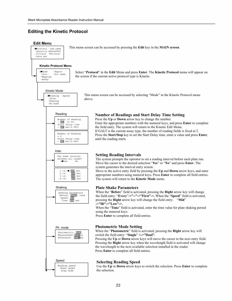
iMark Microplate Absorbance Reader Instruction Manual
23
Kit name for 01 raquoGAP TEST IgGlaquo uarr [ABC]
Kit name
Calculation
Mapping
Assay
Assay type selection raquo[General KINETIC] GALT assay
Calculation Param CC Limit 0910
Calcrange 10 - 20
Select Mapping mode raquoManual mapping bullAutomatic mapping
raquo[Linregression] bullAbsorbance bullKINETIC Plots
Report
Plate Mapping See Plate Map setting procedure
Result = (R2 ndash R1)k k = 999999 R11st Reading R22nd Reading
If GALT
Setting the Kit Name Use the Up and Down arrow keys to select alphabet from ldquoArdquo to ldquoZrdquo and space Use the Number keys for numeric input Use the Right arrow key to move the cursor to the right Use the Left arrow key to return to the Protocol Menu screen Pressing ldquoFUNCrdquo key will change the character mode Upper case alphabet -gt Lower case alphabet -gt symbol The current character mode is indicated on the lower right corner of the LCD
Kinetic Protocol Menu
Selecting Kinetic Assay Type Move the cursor to the desired Assay type by pressing the Up or Down arrow keys Press Enter to complete the selection The item with mark ldquo[ ]rdquo is the currently selected item GALT assay Result = factor x (2nd Read ndash 1st Read)
Selecting Report Type Move the cursor to the desired report type by pressing the Up or Down arrow keys Pressing the Right arrow key will select or deselect the item Press Enter to complete the selection Note When GALT assay is selected ldquoGALT reportrdquo shall be the only one option on this screen
raquoMode bullReport bullCalc bullKit name bullMapping bullAssay
Calculation Parameter Setting When the ldquoCC Limitrdquo field is activated pressing the numeral key will enter the desired numbers Press Enter to complete all field entries If the GALT Reports is activated pressing the numeral keys will enter the desired numbers Press Enter to complete all field entries
iMark Microplate Absorbance Reader Instruction Manual
24
Checkmark Value Setting (Administrator only)
raquoSerial Report bullLinearity ref bullMaxCV bullFilter Check ref
Checkmark Protocol Menu
raquoSerial 0000 Reptype Simple
405nm S10158 Linearity S20309 reference S31401 S42109
MaxCV raquoS115 Linearity S205 reference S302 S402
Filter max min 4051875 0329 4501167 0954 darr 4920596 0103
Serial Report
Linearity reference
Max CV
Filter check reference
Filter max min uarr 5401875 0329 6201167 0954 6900596 0103
Setting the Serial Number and Report Type Pressing the Up and Down arrow keys will move the cursor and change the field entry When ldquoSerial rdquo field is active enter the serial number that will be shown in the data sheet of the Checkmark plate using the numeral keys When the ldquoRep typerdquo field is active pressing the Right arrow key will switch the report type between ldquoSimplerdquo and ldquoFullrdquo
Setting the Linearity Reference Value Pressing the Up or Down arrow keys will move the field entry from S1 to S4 Pressing the Right arrow key will change the wavelength 405 nm-gt450 nm-gt492 nm-gt540 nm-gt620 nm-gt690 nm Use the numeral keys for the reference value setting Pressing Enter will complete all field entries at all wavelength
Max CV setting Pressing the Up or Down arrow keys will move the field entry from S1 to S4 Use the numeral keys for the Max CV setting Press Enter to complete all field entries
Setting the Filter Check Reference Value Initial screen shows the reference entries for 405 nm to 492 nm and pressing the Down arrow key at the bottom of the screen entries will scroll to the next page for 540 nm to 690 nm Pressing the Up Down and Right arrow keys will move the field entry Use the numeral keys for the filter check reference value setting Press Enter to complete all field entries
Select ldquoProtocolrdquo in the Edit Menu and press Enter The Checkmark Protocol Menu will appear on the screen if the current active protocol type is Checkmark mode
Edit Menu raquoProtocol bullLabname bullSecurity bullSaveSTDC bullFilters bullPrinter bullDate set
This menu screen can be accessed by pressing the Edit key in the MAIN screen
iMark Microplate Absorbance Reader Instruction Manual
25
Editing End Point Protocol
Upper Limit= 2000 Lower Limit= 0000 input range 0ndash3500 Upper gt Lower
Standard menu raquoSTD information
bullCurvefit bullRecall STD Curve
raquoCutoff bullMode bullReport bullMapping bullLimit bullKit name bullSTDs
Cutoff
See Plate Map setting procedure
See Standard setting procedure
See Mode setting procedure
raquo[Not use] bullRatio bullConstant bullContrl bullFormula
raquoSet photo mode bullSet shaking bullSet read mode
Select mapping mode raquoManual mapping bullAutomatic mapping
Mapping
Mode
Report
STDs
Limit
Kit name for 01 raquoGAP TEST IgGlaquo uarr [ABC]
Kit name See Kit name setting in Editing Kinetic Protocol
See Cutoff setting procedure
Select ldquoProtocolrdquo in Edit Menu screen above and press Enter The End point Protocol Menu will appear on the screen if the current active protocol type is End point mode
End Point Protocol Menu
raquo[Raw] bullMtx bullCnc bullAbs bullCut bullDif bullLim bullCrv
If ldquoDifrdquo selected
[Raw] bullMtx bullCncbullAbs bullCut [Dif] bullLim bullCrv raquorow odd-even
Seting the Report Type Use the Up and Down Arrow key to move the cursor and press the Right Arrow key to select or deselect the report type Selected report type is marked as ldquo[ ]rdquo Press Enter to complete the selection
Setting the Limit Value Use the Up and Down Arrow key to move the cursor and enter the OD value using the numeral keys The OD value range is 0000 - 3500 Press Enter to complete the selection
Edit Menu raquoProtocol bullLabname bullSecurity bullSaveSTDC bullFilters bullPrinter bullDate set
This menu screen can be accessed by pressing the Edit key in the MAIN screen
iMark Microplate Absorbance Reader Instruction Manual
26
Cutoff Setting Procedure
Cutoff Setting Menu This menu is entered by choosing Cutoff in the End Point Protocol Menu It is used to set the cutoff type The cutoff type marked with ldquo[ ]rdquo is the current selection The Up and Down arrow keys move the cursor to the desired item in the menu list When the desired parameters have been selected press Enter twice to accept the selection and to continue to the next screen Not use means that the reader does not generate the cutoff report Four types of cutoff are supported
1 Cutoff Constant 2 Cutoff Control 3 Cutoff Formula 4 Cutoff Ratio
a Cutoff Constant
Selection of SingleRanged Cutoff Constant This menu selects Single or Ranged cutoff type The cutoff type marked with ldquo[ ]rdquo is the current selection The Enter key seals the selection and resumes to the next setting screen
Single Cutoff Constant The Numerical keys and the Decimal point key are used to enter the positive and gray zone values The Right arrow key is used to select the unit The Up and Down arrow keys move the cursor to the desired parameter of the single cutoff The Enter key sets all values and selection of the cutoff constant and returns the user to the previous screen Ranged Cutoff Constant The Numerical keys and the Decimal point key are used to enter the positive and negative values The Right arrow key is used to select the unit The Up and Down arrow key moves the cursor to the desired ranged cutoff parameters The Enter key sets all values and selection of the cutoff constant and returns to the previous screen NOTE Two available Cutoff constants are ldquoAbsorbancerdquo and ldquoConcentrationrdquo If Abs is chosen the Absorbance cutoff will be done with the cutoff constant parameters defined and the absorbance report is generated For other units defined in the curve fit setting the Concentration value using the curve fit and then cutoff is done with the cutoff constant parameters defined and the concentration value of each well It is necessary to set the curve fit parameters
raquoNot usex bullRatio [Const] bullContrl bullFormula
raquoPositive gt= 9999 Gray zone 50 Unit moll
raquoPositive gt= 9999 Negative lt 1999 NegativeltPositive Unit moll
raquoRanged cutoff [Single cutoff]
Single cutoff
Ranged
iMark Microplate Absorbance Reader Instruction Manual
27
b Cutoff Control
Selection of SingleRanged Cutoff Control This menu screen selects Single or Ranged cutoff type The cutoff type marked with ldquo[ ]rdquo is the current selection The Enter key seals the selection and resumes to the next setting screen
Single Cutoff Control The Numerical keys are used to enter the gray zone value The unit is fixed to Abs The Enter key sets the value of the cutoff control and returns to the previous screen Ranged Cutoff Control There is no parameter to set for the ranged cutoff control The Enter key returns to the previous screen NOTE CNx is the mean absorbance value of Negative control wells and CPx is the mean absorbance value of Positive control wells These wells are defined in the plate map setting The cutoff is done with the Positive and Negative value to the absorbance value of each well
c Cutoff Formula
Selection of Formula This menu screen selects a formula for cutoff calculation The formula marked with ldquo[ ]rdquo is the current selection The Up and Down arrow keys move the cursor to the desired formula type The movement of the cursor follows the scroll of this screen The Enter key marks the selection and advances the user to the next setting screen The supported formula types are
1 k CNx 2 k CPx 3 k COx 4 CNx k 5 CPx k 6 COx k 7 k + CNx 8 k + CPx 9 k + COx 10 kCNx + CPx 11 ( CNx + CPx ) k 12 k1CNx + k2CPx
Coefficient for Cutoff Formula 1 to 11 The Numerical keys and the Decimal point key are used to enter the coefficient k and gray zone values The Up and Down arrow key moves the cursor to the desired parameter of the cutoff formula The Enter key sets all values of the cutoff formula and returns to the previous screen
Positive gt= CNx Gray zone 50 Unit Abs
Positive gt= CPx Negative lt CNx Unit Abs
Enter key to accept
raquoRanged cutoff [Single cutoff]
Single cutoff
Ranged
Input coefficient k = 001 (001-10) Gray zone 50(0-99)
k CNx k CPx k COx CNx k CPx k COx k k + CNx k + CPx k + COx k CNx + CPx (CNx + CPx) k
uarr raquoCNx k bullCPx k bullCOx k darr bullk + CNx
Select formula raquo[kCNx ] bullkCPx darr bullkCOx
uarr raquok + CPx bullk + COx bullkCNx + CPx darr bull(CNx + CPx) k
uarr raquok1CNx + k2CPx
Page-1
Page-2
Page-3
Page-4
iMark Microplate Absorbance Reader Instruction Manual
28
Coefficient for Cutoff Formula 12 The Numerical keys and the Decimal point key are used to enter the coefficient k1 and k2 and gray zone values The Up and Down arrow key moves the cursor to the desired cutoff formula The Enter key sets the all values of the cutoff formula and returns to the previous screen NOTE CNx is the mean absorbance value of Negative control wells CPx is the mean absorbance value of Positive control wells and COx is the mean absorbance value of Cutoff control wells These wells are defined on the plate map setting The cutoff value is calculated using the defined formula with the defined values and coefficients
d Cutoff Ratio
Ratio to Calibrator In this screen there are three items for setting the ratio to calibrator The Up and Down arrow key moves the cursor to the desired item in the menu list The Enter key seals the selection and resumes to the next setting screen
Concentration of Calibrator The Numerical keys and the Decimal point key are used to enter the calibrator concentration value The Enter key sets the value and returns to the previous screen Unit of Calibrator Seventeen standard units are supported The unit marked with ldquo[ ]rdquo is the current selection The setting procedure is the same as the unit selection of Standards Cutoff Value Setting This menu screen selects Single or Ranged cutoff type The cutoff type marked with ldquo[ ]rdquo is the current selection The Enter key marks the selection and continues to the next setting screen Single Cutoff Control The Numerical keys are used to enter the Positive cutoff concentration value and gray zone value The Enter key sets these cutoff ratio values and returns to the previous screen Ranged Cutoff Control The Numerical keys are used to input the Positive and the Negative cutoff concentration values The Enter key sets these cutoff ratios and returns to the previous screen NOTE The calibrator concentration value is used to convert the absorbance value of each well into a concentration value The ratio of ConcentrationAbsorbance of Calibrator well is applied to the conversion The cutoff uses defined Positive and Negative values to the converted concentration value of each well
Input coefficient k1 = 001 (001-10) k2 = 100 (001-10) Gray zone 50(0-99)
k1 CNx + k2 CPx
Ratio to Calibrator raquoConcentration bullUnit bullCutoff value
Concentration 9999 unit moll
uarrraquo 01 ugdl 02 ngml 03[ pgml] darr 04 pmml
raquoPositive gt= 9999 Gray zone 50
Unit moll
raquoPositive gt= 9999 Negative lt 9999 NegativeltPositive
Unit moll
raquoRanged cutoff [Single cutoff]
Concentration
Unit
Cutoff value
Single cutoff
Ranged cutoff
iMark Microplate Absorbance Reader Instruction Manual
29
Standard Setting Procedure
Standard Curve Setting Menu This menu screen is entered by choosing STDs in the End Point Protocol Menu screen It is used to set the concentration data and the curve fit type for a standard curve or to recall a memorized standard curve The Up and Down arrow key moves the cursor to the desired item in the menu list The Enter key seals the selection and continues to the next setting screen
a STD Information Setting
STD Information In this screen there are three items for setting the concentration data of standards The Up and Down arrow keys move the cursor to the desired item in the menu list The Enter key seals the selection and continues to the next setting screen
Number of Standards The Numerical keys are used to enter the number of standards ldquo0rdquo means that the curve fit report is not used The Enter key sets the number and returns to the previous screen The maximum number of standards is 12 Concentration The Numerical keys and the Decimal point key are used to enter the concentration values of standards The Up and Down arrow keys move the cursor to the desired position The movement of the cursor also follows the scroll of this screen The Enter key sets all values of the concentration of standards and returns to the previous screen Unit Seventeen units are supported The unit marked with ldquo[ ]rdquo is the current selection The Up and Down arrow keys move the cursor to the desired unit type The movement of the cursor also follows the scroll of this screen Press Enter twice to select the unit type and to return to the previous screen The supported types of unit are
1 moll 11 pgml 2 m moll 12 Uml 3 u moll 13 IUml 4 n moll 14 uIUml 5 p moll 15 mIUml 6 mgl 16 EU 7 ngl 17 Arbit 8 pgl 9 ugdl 10 ngml
STD information raquoNumber of STD bullConcentration bullUnit
STD 1 0512 STD 2 1012 STD 3 1512 darr STD 4 2053
Standard menu raquoSTD information bullCurve fit bullRecall STD curve
Concentration
Number of STD
Number of STD = 05 (0 2ndash12)
uarrraquo 01 ugdl 02 ngml 03[ pgml] darr 04 pmml
Unit
iMark Microplate Absorbance Reader Instruction Manual
30
b Curve Fit Setting
Curve Fit In this screen there are two choices to set the curve fit The Up and Down arrow keys move the cursor to the desired item in the menu list The Enter key seals the selection and resumes to the next setting screen
Curve Fit Type 10 types of curve fit are supported as below The curve fit type marked with ldquo[ ]rdquo is the current selection The Up and Down arrow key moves the cursor to the desired curve fit type The movement of the cursor follows the scroll of this screen Press Enter twice to select the unit type and to return to the previous screen The supported curve fit types are
1 5P Logistic Rodbard 2 4P Logistic Rodbard 3 5P Logistic Cook-Wilkenson 4 4P Logistic Cook-Wilkenson 5 5P Exponential 6 Sigmoid Logistic 7 Linear regression 8 Quadratic regression 9 Cubic 10 Point To Point regression
Graph Axis Four types of graph are supported The curve fit type marked with ldquo[ ]rdquo is the current selection The Up and Down arrow keys move the cursor to the desired graph type Press Enter twice to select the unit type and to return to the previous screen The supported graph types are
1 Log - Log 2 Log - Linear 3 Linear - Log 4 Linear - Linear
uarr 5p logisticRodb raquo 4p logisticRodb [5p logisticCook] darr 4p logisticCook
raquo X-Log Y-Log [X-Log Y-Lin] X-Lin Y-Log X-Lin Y-Lin
Curve fit type
Graph axis
Curve fit setting raquoCurve fit type bullGraph axis
iMark Microplate Absorbance Reader Instruction Manual
31
c Recall STD Curve Setting
Recall Setting of Standard Curve In this screen there are two items for setting the Recall STD curve as below The Up and Down arrow keys move the cursor to the desired item in the menu list
1 Recall setting (YesNo) 2 Selecting the storage number of standard curves (1 -gt 5)
Recall Setting Move the cursor to the desired position using the Up Down or Right arrow keys Enter key accepts the setting and returns the user to the standard menu screen
Yes Recalling of the standard curve is active No Recalling of the standard curve is inactive
Storage Number Selection Five memories are selectable The vacant memory (marked with asterisks on the date and time field) is also selectable It is necessary to save a standard curve before using its protocol Move the cursor to the desired position using the Up and Down keys This setting screen consists of two parts The Right arrow key is used to switch the indication field between the date and time to the standard curve name Move the cursor to the desired position using the Up and Down keys The Enter key accepts the storage number and returns to the standard menu screen NOTE If the recall of standard curve is active (the recall setting is ldquoYesrdquo) the standard information setting and the curve fit setting will be invalidated and their setting screens will not open
Recall STD curve raquoRecall setting bullSelect STD curve
Recall setting raquoYes No
Recall setting
Select STD Curve raquo1160304 1125
2 darr 3150304 1030
Select STD Curve uarrraquo4
5
Select STD Curve raquo1 STD Curve 1
2 STD Curve 2 darr 3 STD Curve 3
Select STD Curve uarrraquo4 STD Curve 4
5 STD Curve 5
Select STD curve
Right arrow key
iMark Microplate Absorbance Reader Instruction Manual
32
Mode Setting Procedure
Mode Setting Menu This menu screen is entered by choosing the Mode in the End Point Protocol Menu screen or the Kinetic Protocol Menu screen It is used to set the plate reading conditions The Up and Down arrow keys move the cursor to the desired item in the menu list The Enter key seals the selection and resumes to the next setting screen
a Set Photo Mode
Photo Mode In this screen the user chooses Single or Dual wavelength measurement and assigns the measurement and reference (for dual wavelength measurement) filters The assignment of the reference filter appears for dual wavelength measurement The Up and Down arrow keys move the cursor to the desired parameter The Right arrow key chooses SingleDual wavelength measurement and selects the installed filter on the Filters of Edit Menu screen The Enter key seals the selection and returns to the previous screen
b Set Shaking
Shaking In this screen the user selectsdeselects shaking function sets the shaking strength and enters the shaking time A shaking time of 0s indicates no shaking The maximum shaking time is 999 seconds The Up and Down arrow key moves the cursor to the desired parameters The Right arrow key toggles between YesNo (SelectDeselect) shaking or selects strength LowMiddleHigh The Numerical keys are used to enter the shaking time The Enter key seals the selection and returns the user to the previous screen
c Set Read Mode
Read Mode In this screen the user chooses Fast or Step reading and also chooses Normal or Evaluation mode The ldquo[ ]rdquoindicates the current selection The Up and Down arrow key moves the cursor to the desired parameters The Right arrow key chooses FastStep speed or chooses NormalEval mode The Enter key seals the selection and returns to the previous screen The followings are the description of each read mode parameter Reading speed
Fast reading 6 secsingle wavelength reading 10 secdual wavelength reading
Step reading 15 secsingle wavelength reading 30 secdual wavelength reading
Reading mode
Normal mode Plate reading once Evaluation mode Four plate readings per one of measurement are performed and
the average data of their plate readings is generated as a plate data
Photometric Dual Measurement400 nm Reference 655 nm
Set Shake parameters ShakeYes SpeedMid Time 199sec(0-999)
raquoReading speed [Fast ] Step bullRead mode [Normal] Eval
raquoSet Photo mode bullSet shaking bullSet read mode
Photometric Single Measurement400 nm
iMark Microplate Absorbance Reader Instruction Manual
33
Plate Map Setting Procedure
Select Mapping Mode Menu This menu screen is entered by choosing Mapping in the End Point Protocol Menu screen or the Kinetic Protocol Menu screen It is used to map the plate format The Up and Down arrow keys move the cursor next to the desired item of menu list The Enter key seals the selection and changes this screen to the next setting screen
a Manual Mapping
Manual Mapping In this screen the user can set the plate format manually Ten well types can be set Well types The supported well types are
Well type Indication on LCD
1 Blank B 2 Sample X00hellipX99 3 Standard S01hellipS99 4 In-kit Control Positive Control CP0hellipCP9 5 Weak Positive Control CW0hellipCW9 6 Negative Control CN0hellipCN9 7 Cutoff Control CO0hellipCO9 8 Calibrator CL0hellipCL9 9 QC Control QC0hellipQC9 10 Empty well -
The key assignments of well type are ldquo0EMPrdquo Empty well ldquo5QCrdquo Quality Control well ldquo1SMPrdquo Sample well ldquo6CALrdquo Calibrator well ldquo2BLKrdquo Blank well ldquo7CPrdquo Positive Control well ldquo3STDrdquo Standard well ldquo8CNrdquo Negative Control well ldquo4COrdquo Cutoff Control well ldquo9CWrdquo Weak Positive Control well
Two Edit Modes in Plate Mapping There are two editing modes for well type input mode and for well number input The current input mode is displayed at the upper left corner of the screen When using the well type input mode the mode sign is ldquo[F]rdquo When using the well number input mode the mode sign is ldquoNrdquo The cursor that encloses the editing position of well has two types of enclosures depending on the mode For example ldquo[S01]rdquo accepts the well type keys that be assigned to the numerical keys and ldquoS01rdquo accepts the numerical input The mode is easily changed with the Decimal point key Key Functions The Up Down Right and Left arrow keys move the cursor to the desired well The movement of the cursor follows the scroll of this screen The Left arrow key will return the screen to the preceding screen or the select Mapping mode Menu only if the cursor is on column 1 At this time the selection screen appears (see the left figure) The Decimal point key changes the input mode The Numerical keys have two functions one to input the number and another to select a well type The Enter key checks the consistency between the edited plate map and other parameters memorizes the plate map into the protocol and changes this screen back to the preceding screen If it finds any inconsistency a warning message will appear on the screen
Select Mapping mode raquoManual mapping bullAutomatic mapping
N 1 2 3 4 A B CN1 S01 S01 B B CN1 S02 S02 C B CN2 S03 S03 [F] 5 6 7 8 A X11 X12 X13 X14 B X21 X22 X23 X24 C X31 X32 X33[X34]
Discard change 1Yes 2No Press 1 or 2 key
iMark Microplate Absorbance Reader Instruction Manual
34
Acceptable Number Ranges for each well type 1 Blank and Empty wells do not use numbers 2 Sample and Standard wells 00 - 99 3 Standard wells 01 - 99 4 Control and Calibrator wells 0 - 9
b Automatic Mapping
Automatic Mapping The user can input the number of each well type in this screen These defined numbers are used to set a plate map automatically Well type Nine well types are available
1 BLK Blank (0-gt10) 2 CN Control CN (0-gt9) 3 CW Control CW (0-gt9) 4 CP Control CP (0-gt9) 5 CO Control CO (0-gt9) 6 QC Control QC (0-gt9) 7 CAL Calibrator (0-gt9) 8 SMP Sample (0-gt96) 9 REP Replicate well (1-gt4)
It is possible to define the number of blanks samples calibrators and controls But the number of Standards is not included because standards are defined at the Standard Setting Menu The number of replicate wells is also included It is used for replicating each well type individually Key Functions The Up Down Right and Left arrow keys are used to move the cursor to the next position The Numerical keys are used to input the mapping parameters The Enter key accepts the mapping parameters and sets a plate map automatically using these parameters During the execution of the plate mapping the Plate auto-mapping completed message appears on the screen After that the user returns automatically to the previous Protocol Menu screen If the Left arrow key is pressed at the left end position of the cursor the left figure will appear on the screen If the user chooses Yes the system will return to the previous Protocol Menu screen If the user chooses No the system will stay in this setting screen Assigning Order and Direction of plate mapping Assigning Order The order of blanks standards samples calibrators and controls are fixed as follows Numbering for standards samples calibrators and controls is started at 1
1 Blank 2 Standard 1 -gt12 ---- NOTE 3 Control CN 1-gt9 4 Control CW 1-gt9 5 Control CP 1-gt9 6 Control CO 1-gt9 7 Control QC 1-gt9 8 Calibrator 1-gt9 9 Sample 1-gt96 10 Empty well NOTE If ldquoCutoff Controlrdquo ldquoValue by Formulardquo or ldquoRatio to Calibratorrdquo is
selected for the Cutoff plate mapping skips arranging the standards Assigning Direction The placing direction of the mapping is limited to the column direction as below
Column direction A1 -gt H1 A2 -gt H2 ----- A12 -gt H12
Discard change 1Yes 2No Press 1 or 2 key
Automatic mapping BLK= 1 CP = 1 CAL= 0 CN = 1 CO = 0 SMP=93 CW = 0 QC = 0 REP= 1
Plate auto-mapping completed
iMark Microplate Absorbance Reader Instruction Manual
35
Warning and Error of Automatic Mapping Warning screen If the total number of wells mapped exceeds 96 wells a warning message in the left figure appears on the screen The calculation of the total number of mapping wells is as follows
(Blanks+Standards+CNs+CWs+CPs+COs+QCs+Calibrators+Sample)Replicates The plate mapping is executed normally and the exceeded part is invalidated Error screen If one or more mapping parameters are over the input range an error message in the left figure will appear on the screen On the third line of the LCD the name of the parameter which is out of range and its input range will appear
Example ldquoBLK 0 ndash 10rdquo In case there is more than one error the first parameter of errors is indicated By pressing any key the user returns to the automatic mapping screen Example of automatic mapping An example of automatic mapping is as below 1 Conditions of each parameter
Blank = 1 Standard = 8 Control CN = 2 CW = 0 CP = 2 CO = 0 QC = 0 Calibrator = 1 Sample = 32 Replicate number = 2
2 Plate mapping data
1 2 3 4 5 6 7 8 9 10 11 12 A B C D E F G H
B B S1 S1 S2 S2 S3 S3
S4 S4 S5 S5 S6 S6 S7 S7
S8 S8 CN1 CN1 CN2 CN2 CP1 CP1
CP2 CP2 CL1 CL1 X1 X1 X2 X2
X3 X3 X4 X4 X5 X5 X6 X6
X7 X7 X8 X8 X9 X9 X10 X10
X11 X11 X12 X12 X13 X13 X14 X14
X15 X15 X16 X16 X17 X17 X18 X18
X19 X19 X20 X20 X21 X21 X22 X22
X23 X23 X24 X24 X25 X25 X26 X26
X27 X27 X28 X28 X29 X29 X30 X30
X31 X31 X32 X32 E E E E
Warning The total Of mapped wells has Exceeded 96 Press any key
Entered value is Out of range BLK 0 ndash 10 Press any key
iMark Microplate Absorbance Reader Instruction Manual
36
Instrument Maintenance
Caution Electrical shock hazard Always disconnect the instrument from the AC power source before opening the service compartment
Caution The lamp and the lamp cover may be very hot Use caution and allow the lamp to cool
before attempting service
Installing Interference Filters 1 With the power off open the rear cover of the instrument by pressing the
release latch located on the top left portion of the cover 2 Locate the filter wheel on the left side of the instrument Note that the
filter wheel has eight filter positions 3 Rotate the filter wheel to the desired filter Grasp the top of filter frame
and pull up to remove the filter 4 Insert the new filter into the desired filter position 5 Ensure that the new filter is added to the filter list as follows Main
menu-gtEdit-gtFilters
Changing the Lamp 1 With the power off open the rear cover of the instrument by pressing the
release latch located on the top left portion of the cover 2 Remove the two screws on the black plastic cover and carefully remove
the plastic cover 3 Remove the screw on the metal cover Lift the cover up and away from
the instrument This will allow the lamp to be pulled free from the lamp housing
4 Holding the ceramic base in one hand and the lamp housing in the other carefully pull the lamp free of the base
5 Carefully insert the new lamp firmly in the ceramic base Apply even pressure when inserting the lamp so that the bulb dose not become misaligned in the reflector housing Be extremely careful not to touch the front glass of the lamp during installation
6 Position the new lamp into the housing so that the plastic guides hold the flange of the lamp
7 Carefully place the metal cover over the lamp Tighten the screw 8 Replace the plastic cover and tighten the screws 9 Close the rear cover
iMark Microplate Absorbance Reader Instruction Manual
37
Troubleshooting and Error Messages
The iMark Microplate Reader constantly monitors several functions and displays appropriate messages on the LCD as errors are encountered
Error Recommendation
LCD appears blank on power up
a Power is not turned on The AC outlet is non-functional
b Unit is not plugged into AC outlet or power code is not attached to the instrument
Check power cord connections at outlet and on the rear panel of the instrument
1
c The AC outlet is non-functional Check circuit breakers or fuses
Instrument displays ldquoLight bulb errorrdquo message indicating that the bulb is burned out
Check whether lamp is emitting light
a Lamp is not emitting light Replace the lamp as described in x
2
b Lamp is emitting light Check the alignment of the lamp in the housing Align or replace the lamp if necessary
Printer will not print on command
3
a Printer paper is not installed properly Verify that the paper is properly installed Refer to x for details
Plate carriage jams during reading and ldquoPlate carrier errorrdquo is displayed
a Plate is not seated in carriage properly Press the STOP button immediately Position the plate carefully in the carriage making certain that it is properly seated
4
b Plate height is exceeding 16mm Use Microplate which is less than 16mm in height
5 LCD displays ldquoFilter missingrdquo Install a filter in the empty position Select the installed filter by pressing Edit key
6 LCD displays ldquoFilter disk jammedrdquo indicating that the filter wheel is not turning freely
Turn off the instrument and inspect the filter wheel Turn by hand to verify that the wheel is moving freely Make sure all the filters are properly installed and firmly seated Contact your Bio-Rad representative if the filter wheel is jammed or if the problem persists
7 LCD displays ldquoFilter not installedrdquo Enter the Edit Menu by pressing Edit key and set up the filters
iMark Microplate Absorbance Reader Instruction Manual
38
Wells have color but absorbance values seem low
a Incorrect filter used for measurement andor reference wavelength
Check wavelength used in analysis Read plate in single wavelength mode at all wavelength to verify that the proper filter was used The measurement wavelength should produce the highest absorbance
b The best measurement wavelength filter for the substrate in use has not been installed in the filter wheel
Check references for the substrate you are using or determine the best measurement wavelength by analyzing the substrate product on a scanning spectrophotometer Custom filters are available from 400 to 750 nm
8
c The filters have been switched in the wheel Check that the filters are installed in the correct position
9 ldquoPrinter errorrdquo displayed Check for paper jam Install the printer paper correctly
10 ldquoBattery errorrdquo displayed The internal battery is almost dead Contact your local Bio-Rad office
11 The following messages are displayed ldquoMemory errorrdquo ldquoCalendar errorrdquo ldquoLCD hardware errorrdquo ldquoPrinter errorrdquo ldquoLight level errorrdquo ldquoDA conversion errorrdquo ldquoAD conversion errorrdquo ldquoEEPROM errorrdquo ldquoUSB errorrdquo
Contact your local Bio-Rad office if these problems persist
iMark Microplate Absorbance Reader Instruction Manual
39
Instrument Specifications Computer interface USB 20
Plate shaking 3 speeds (low mid high) Programmable time period 0 - 999 seconds
Data storage The most recent 10 data plates for end-point most recent 2 data plates of 30 readings for kinetic readings protocol data and calendarclock function shall be kept in memory by a lithium battery even when the power is off Average lifetime of the battery shall be 5 years
Warm-up time 3 minutes
Photometric Methods Single and dual wavelength
Photo detectors 8 silicon photodiodes for measurement and 1 silicon photodiode for reference
Light source Tungsten halogen lamp 20W with 3000 hours average lifetime
Spectral range 400 nm to 750 nm
Interference filters Wavelength tolerance plusmn30 nm Band width 10 nm typically
Filter capacity 8 filters
Reading speed Fast Reading 6 sec with single wavelength reading 10 sec with dual wavelength reading
Step Reading 15 sec with single wavelength reading 25 sec with dual wavelength reading
These times are minimum interval times between repetitive reads using onboard KINETIC protocol
Indication range 0000 to 35 OD
Resolution 0001 OD
Accuracy plusmn10 or 0010 from 0 to 30 OD at 490 nm
Linearity plusmn10 from 0 to 20 OD plusmn20 from 0 to 30 OD
Reproducibility 10 or 0005 OD from 0 to 20 OD 15 from 20 to 30 OD
Inter-channel variability 15 or 0005 OD from 0 to 30 OD
Stability and Drift 0010 OD at OD=1 with single wavelength reading
Built-in Printer Thermal printer Paper width 80mm
Line Voltage Universal input 100 - 240 VAC 5060Hz
Power consumption (max) 100 VA max
Dimensions (W x D x H 346 mm x 377 mm x 164 m mm
Weight 55 kg
Operating Environment 15ordmC - 40ordmC up to 90 relative humidity without condensation
Storage Temperature 10ordmC - 50ordmC up to 90 relative humidity without condensation
Life ScienceGroup
07-0816 0108 Sig 120710013301i Rev A USEG
Bio-RadLaboratories Inc
Web site wwwbio-radcom USA 800 4BIORAD Australia 61 02 9914 2800 Austria 01 877 89 01 Belgium 09 385 55 11 Brazil 55 21 3237 9400 Canada 905 364 3435 China 86 21 6426 0808 Czech Republic 420 241 430 532 Denmark 44 52 10 00 Finland 09 804 22 00 France 01 47 95 69 65Germany 089 318 84 0 Greece 30 210 777 4396 Hong Kong 852 2789 3300 Hungary 36 1 455 8800 India 91 124 4029300 Israel 03 963 6050 Italy 39 02 216091 Japan 03 6361 7000 Korea 82 2 3473 4460 Mexico 52 555 488 7670 The Netherlands 0318 540666 New Zealand 0508 805 500 Norway 23 38 41 30 Poland 48 22 331 99 99 Portugal 351 21 472 7700 Russia 7 495 721 14 04 Singapore 65 6415 3188 South Africa 27 861 246 723 Spain 34 91 590 5200 Sweden 08 555 12700 Switzerland 061 717 95 55 Taiwan 886 2 2578 7189 United Kingdom 020 8328 2000
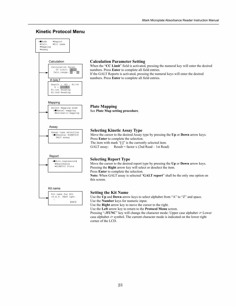
iMark Microplate Absorbance Reader Instruction Manual
24
Checkmark Value Setting (Administrator only)
raquoSerial Report bullLinearity ref bullMaxCV bullFilter Check ref
Checkmark Protocol Menu
raquoSerial 0000 Reptype Simple
405nm S10158 Linearity S20309 reference S31401 S42109
MaxCV raquoS115 Linearity S205 reference S302 S402
Filter max min 4051875 0329 4501167 0954 darr 4920596 0103
Serial Report
Linearity reference
Max CV
Filter check reference
Filter max min uarr 5401875 0329 6201167 0954 6900596 0103
Setting the Serial Number and Report Type Pressing the Up and Down arrow keys will move the cursor and change the field entry When ldquoSerial rdquo field is active enter the serial number that will be shown in the data sheet of the Checkmark plate using the numeral keys When the ldquoRep typerdquo field is active pressing the Right arrow key will switch the report type between ldquoSimplerdquo and ldquoFullrdquo
Setting the Linearity Reference Value Pressing the Up or Down arrow keys will move the field entry from S1 to S4 Pressing the Right arrow key will change the wavelength 405 nm-gt450 nm-gt492 nm-gt540 nm-gt620 nm-gt690 nm Use the numeral keys for the reference value setting Pressing Enter will complete all field entries at all wavelength
Max CV setting Pressing the Up or Down arrow keys will move the field entry from S1 to S4 Use the numeral keys for the Max CV setting Press Enter to complete all field entries
Setting the Filter Check Reference Value Initial screen shows the reference entries for 405 nm to 492 nm and pressing the Down arrow key at the bottom of the screen entries will scroll to the next page for 540 nm to 690 nm Pressing the Up Down and Right arrow keys will move the field entry Use the numeral keys for the filter check reference value setting Press Enter to complete all field entries
Select ldquoProtocolrdquo in the Edit Menu and press Enter The Checkmark Protocol Menu will appear on the screen if the current active protocol type is Checkmark mode
Edit Menu raquoProtocol bullLabname bullSecurity bullSaveSTDC bullFilters bullPrinter bullDate set
This menu screen can be accessed by pressing the Edit key in the MAIN screen
iMark Microplate Absorbance Reader Instruction Manual
25
Editing End Point Protocol
Upper Limit= 2000 Lower Limit= 0000 input range 0ndash3500 Upper gt Lower
Standard menu raquoSTD information
bullCurvefit bullRecall STD Curve
raquoCutoff bullMode bullReport bullMapping bullLimit bullKit name bullSTDs
Cutoff
See Plate Map setting procedure
See Standard setting procedure
See Mode setting procedure
raquo[Not use] bullRatio bullConstant bullContrl bullFormula
raquoSet photo mode bullSet shaking bullSet read mode
Select mapping mode raquoManual mapping bullAutomatic mapping
Mapping
Mode
Report
STDs
Limit
Kit name for 01 raquoGAP TEST IgGlaquo uarr [ABC]
Kit name See Kit name setting in Editing Kinetic Protocol
See Cutoff setting procedure
Select ldquoProtocolrdquo in Edit Menu screen above and press Enter The End point Protocol Menu will appear on the screen if the current active protocol type is End point mode
End Point Protocol Menu
raquo[Raw] bullMtx bullCnc bullAbs bullCut bullDif bullLim bullCrv
If ldquoDifrdquo selected
[Raw] bullMtx bullCncbullAbs bullCut [Dif] bullLim bullCrv raquorow odd-even
Seting the Report Type Use the Up and Down Arrow key to move the cursor and press the Right Arrow key to select or deselect the report type Selected report type is marked as ldquo[ ]rdquo Press Enter to complete the selection
Setting the Limit Value Use the Up and Down Arrow key to move the cursor and enter the OD value using the numeral keys The OD value range is 0000 - 3500 Press Enter to complete the selection
Edit Menu raquoProtocol bullLabname bullSecurity bullSaveSTDC bullFilters bullPrinter bullDate set
This menu screen can be accessed by pressing the Edit key in the MAIN screen
iMark Microplate Absorbance Reader Instruction Manual
26
Cutoff Setting Procedure
Cutoff Setting Menu This menu is entered by choosing Cutoff in the End Point Protocol Menu It is used to set the cutoff type The cutoff type marked with ldquo[ ]rdquo is the current selection The Up and Down arrow keys move the cursor to the desired item in the menu list When the desired parameters have been selected press Enter twice to accept the selection and to continue to the next screen Not use means that the reader does not generate the cutoff report Four types of cutoff are supported
1 Cutoff Constant 2 Cutoff Control 3 Cutoff Formula 4 Cutoff Ratio
a Cutoff Constant
Selection of SingleRanged Cutoff Constant This menu selects Single or Ranged cutoff type The cutoff type marked with ldquo[ ]rdquo is the current selection The Enter key seals the selection and resumes to the next setting screen
Single Cutoff Constant The Numerical keys and the Decimal point key are used to enter the positive and gray zone values The Right arrow key is used to select the unit The Up and Down arrow keys move the cursor to the desired parameter of the single cutoff The Enter key sets all values and selection of the cutoff constant and returns the user to the previous screen Ranged Cutoff Constant The Numerical keys and the Decimal point key are used to enter the positive and negative values The Right arrow key is used to select the unit The Up and Down arrow key moves the cursor to the desired ranged cutoff parameters The Enter key sets all values and selection of the cutoff constant and returns to the previous screen NOTE Two available Cutoff constants are ldquoAbsorbancerdquo and ldquoConcentrationrdquo If Abs is chosen the Absorbance cutoff will be done with the cutoff constant parameters defined and the absorbance report is generated For other units defined in the curve fit setting the Concentration value using the curve fit and then cutoff is done with the cutoff constant parameters defined and the concentration value of each well It is necessary to set the curve fit parameters
raquoNot usex bullRatio [Const] bullContrl bullFormula
raquoPositive gt= 9999 Gray zone 50 Unit moll
raquoPositive gt= 9999 Negative lt 1999 NegativeltPositive Unit moll
raquoRanged cutoff [Single cutoff]
Single cutoff
Ranged
iMark Microplate Absorbance Reader Instruction Manual
27
b Cutoff Control
Selection of SingleRanged Cutoff Control This menu screen selects Single or Ranged cutoff type The cutoff type marked with ldquo[ ]rdquo is the current selection The Enter key seals the selection and resumes to the next setting screen
Single Cutoff Control The Numerical keys are used to enter the gray zone value The unit is fixed to Abs The Enter key sets the value of the cutoff control and returns to the previous screen Ranged Cutoff Control There is no parameter to set for the ranged cutoff control The Enter key returns to the previous screen NOTE CNx is the mean absorbance value of Negative control wells and CPx is the mean absorbance value of Positive control wells These wells are defined in the plate map setting The cutoff is done with the Positive and Negative value to the absorbance value of each well
c Cutoff Formula
Selection of Formula This menu screen selects a formula for cutoff calculation The formula marked with ldquo[ ]rdquo is the current selection The Up and Down arrow keys move the cursor to the desired formula type The movement of the cursor follows the scroll of this screen The Enter key marks the selection and advances the user to the next setting screen The supported formula types are
1 k CNx 2 k CPx 3 k COx 4 CNx k 5 CPx k 6 COx k 7 k + CNx 8 k + CPx 9 k + COx 10 kCNx + CPx 11 ( CNx + CPx ) k 12 k1CNx + k2CPx
Coefficient for Cutoff Formula 1 to 11 The Numerical keys and the Decimal point key are used to enter the coefficient k and gray zone values The Up and Down arrow key moves the cursor to the desired parameter of the cutoff formula The Enter key sets all values of the cutoff formula and returns to the previous screen
Positive gt= CNx Gray zone 50 Unit Abs
Positive gt= CPx Negative lt CNx Unit Abs
Enter key to accept
raquoRanged cutoff [Single cutoff]
Single cutoff
Ranged
Input coefficient k = 001 (001-10) Gray zone 50(0-99)
k CNx k CPx k COx CNx k CPx k COx k k + CNx k + CPx k + COx k CNx + CPx (CNx + CPx) k
uarr raquoCNx k bullCPx k bullCOx k darr bullk + CNx
Select formula raquo[kCNx ] bullkCPx darr bullkCOx
uarr raquok + CPx bullk + COx bullkCNx + CPx darr bull(CNx + CPx) k
uarr raquok1CNx + k2CPx
Page-1
Page-2
Page-3
Page-4
iMark Microplate Absorbance Reader Instruction Manual
28
Coefficient for Cutoff Formula 12 The Numerical keys and the Decimal point key are used to enter the coefficient k1 and k2 and gray zone values The Up and Down arrow key moves the cursor to the desired cutoff formula The Enter key sets the all values of the cutoff formula and returns to the previous screen NOTE CNx is the mean absorbance value of Negative control wells CPx is the mean absorbance value of Positive control wells and COx is the mean absorbance value of Cutoff control wells These wells are defined on the plate map setting The cutoff value is calculated using the defined formula with the defined values and coefficients
d Cutoff Ratio
Ratio to Calibrator In this screen there are three items for setting the ratio to calibrator The Up and Down arrow key moves the cursor to the desired item in the menu list The Enter key seals the selection and resumes to the next setting screen
Concentration of Calibrator The Numerical keys and the Decimal point key are used to enter the calibrator concentration value The Enter key sets the value and returns to the previous screen Unit of Calibrator Seventeen standard units are supported The unit marked with ldquo[ ]rdquo is the current selection The setting procedure is the same as the unit selection of Standards Cutoff Value Setting This menu screen selects Single or Ranged cutoff type The cutoff type marked with ldquo[ ]rdquo is the current selection The Enter key marks the selection and continues to the next setting screen Single Cutoff Control The Numerical keys are used to enter the Positive cutoff concentration value and gray zone value The Enter key sets these cutoff ratio values and returns to the previous screen Ranged Cutoff Control The Numerical keys are used to input the Positive and the Negative cutoff concentration values The Enter key sets these cutoff ratios and returns to the previous screen NOTE The calibrator concentration value is used to convert the absorbance value of each well into a concentration value The ratio of ConcentrationAbsorbance of Calibrator well is applied to the conversion The cutoff uses defined Positive and Negative values to the converted concentration value of each well
Input coefficient k1 = 001 (001-10) k2 = 100 (001-10) Gray zone 50(0-99)
k1 CNx + k2 CPx
Ratio to Calibrator raquoConcentration bullUnit bullCutoff value
Concentration 9999 unit moll
uarrraquo 01 ugdl 02 ngml 03[ pgml] darr 04 pmml
raquoPositive gt= 9999 Gray zone 50
Unit moll
raquoPositive gt= 9999 Negative lt 9999 NegativeltPositive
Unit moll
raquoRanged cutoff [Single cutoff]
Concentration
Unit
Cutoff value
Single cutoff
Ranged cutoff
iMark Microplate Absorbance Reader Instruction Manual
29
Standard Setting Procedure
Standard Curve Setting Menu This menu screen is entered by choosing STDs in the End Point Protocol Menu screen It is used to set the concentration data and the curve fit type for a standard curve or to recall a memorized standard curve The Up and Down arrow key moves the cursor to the desired item in the menu list The Enter key seals the selection and continues to the next setting screen
a STD Information Setting
STD Information In this screen there are three items for setting the concentration data of standards The Up and Down arrow keys move the cursor to the desired item in the menu list The Enter key seals the selection and continues to the next setting screen
Number of Standards The Numerical keys are used to enter the number of standards ldquo0rdquo means that the curve fit report is not used The Enter key sets the number and returns to the previous screen The maximum number of standards is 12 Concentration The Numerical keys and the Decimal point key are used to enter the concentration values of standards The Up and Down arrow keys move the cursor to the desired position The movement of the cursor also follows the scroll of this screen The Enter key sets all values of the concentration of standards and returns to the previous screen Unit Seventeen units are supported The unit marked with ldquo[ ]rdquo is the current selection The Up and Down arrow keys move the cursor to the desired unit type The movement of the cursor also follows the scroll of this screen Press Enter twice to select the unit type and to return to the previous screen The supported types of unit are
1 moll 11 pgml 2 m moll 12 Uml 3 u moll 13 IUml 4 n moll 14 uIUml 5 p moll 15 mIUml 6 mgl 16 EU 7 ngl 17 Arbit 8 pgl 9 ugdl 10 ngml
STD information raquoNumber of STD bullConcentration bullUnit
STD 1 0512 STD 2 1012 STD 3 1512 darr STD 4 2053
Standard menu raquoSTD information bullCurve fit bullRecall STD curve
Concentration
Number of STD
Number of STD = 05 (0 2ndash12)
uarrraquo 01 ugdl 02 ngml 03[ pgml] darr 04 pmml
Unit
iMark Microplate Absorbance Reader Instruction Manual
30
b Curve Fit Setting
Curve Fit In this screen there are two choices to set the curve fit The Up and Down arrow keys move the cursor to the desired item in the menu list The Enter key seals the selection and resumes to the next setting screen
Curve Fit Type 10 types of curve fit are supported as below The curve fit type marked with ldquo[ ]rdquo is the current selection The Up and Down arrow key moves the cursor to the desired curve fit type The movement of the cursor follows the scroll of this screen Press Enter twice to select the unit type and to return to the previous screen The supported curve fit types are
1 5P Logistic Rodbard 2 4P Logistic Rodbard 3 5P Logistic Cook-Wilkenson 4 4P Logistic Cook-Wilkenson 5 5P Exponential 6 Sigmoid Logistic 7 Linear regression 8 Quadratic regression 9 Cubic 10 Point To Point regression
Graph Axis Four types of graph are supported The curve fit type marked with ldquo[ ]rdquo is the current selection The Up and Down arrow keys move the cursor to the desired graph type Press Enter twice to select the unit type and to return to the previous screen The supported graph types are
1 Log - Log 2 Log - Linear 3 Linear - Log 4 Linear - Linear
uarr 5p logisticRodb raquo 4p logisticRodb [5p logisticCook] darr 4p logisticCook
raquo X-Log Y-Log [X-Log Y-Lin] X-Lin Y-Log X-Lin Y-Lin
Curve fit type
Graph axis
Curve fit setting raquoCurve fit type bullGraph axis
iMark Microplate Absorbance Reader Instruction Manual
31
c Recall STD Curve Setting
Recall Setting of Standard Curve In this screen there are two items for setting the Recall STD curve as below The Up and Down arrow keys move the cursor to the desired item in the menu list
1 Recall setting (YesNo) 2 Selecting the storage number of standard curves (1 -gt 5)
Recall Setting Move the cursor to the desired position using the Up Down or Right arrow keys Enter key accepts the setting and returns the user to the standard menu screen
Yes Recalling of the standard curve is active No Recalling of the standard curve is inactive
Storage Number Selection Five memories are selectable The vacant memory (marked with asterisks on the date and time field) is also selectable It is necessary to save a standard curve before using its protocol Move the cursor to the desired position using the Up and Down keys This setting screen consists of two parts The Right arrow key is used to switch the indication field between the date and time to the standard curve name Move the cursor to the desired position using the Up and Down keys The Enter key accepts the storage number and returns to the standard menu screen NOTE If the recall of standard curve is active (the recall setting is ldquoYesrdquo) the standard information setting and the curve fit setting will be invalidated and their setting screens will not open
Recall STD curve raquoRecall setting bullSelect STD curve
Recall setting raquoYes No
Recall setting
Select STD Curve raquo1160304 1125
2 darr 3150304 1030
Select STD Curve uarrraquo4
5
Select STD Curve raquo1 STD Curve 1
2 STD Curve 2 darr 3 STD Curve 3
Select STD Curve uarrraquo4 STD Curve 4
5 STD Curve 5
Select STD curve
Right arrow key
iMark Microplate Absorbance Reader Instruction Manual
32
Mode Setting Procedure
Mode Setting Menu This menu screen is entered by choosing the Mode in the End Point Protocol Menu screen or the Kinetic Protocol Menu screen It is used to set the plate reading conditions The Up and Down arrow keys move the cursor to the desired item in the menu list The Enter key seals the selection and resumes to the next setting screen
a Set Photo Mode
Photo Mode In this screen the user chooses Single or Dual wavelength measurement and assigns the measurement and reference (for dual wavelength measurement) filters The assignment of the reference filter appears for dual wavelength measurement The Up and Down arrow keys move the cursor to the desired parameter The Right arrow key chooses SingleDual wavelength measurement and selects the installed filter on the Filters of Edit Menu screen The Enter key seals the selection and returns to the previous screen
b Set Shaking
Shaking In this screen the user selectsdeselects shaking function sets the shaking strength and enters the shaking time A shaking time of 0s indicates no shaking The maximum shaking time is 999 seconds The Up and Down arrow key moves the cursor to the desired parameters The Right arrow key toggles between YesNo (SelectDeselect) shaking or selects strength LowMiddleHigh The Numerical keys are used to enter the shaking time The Enter key seals the selection and returns the user to the previous screen
c Set Read Mode
Read Mode In this screen the user chooses Fast or Step reading and also chooses Normal or Evaluation mode The ldquo[ ]rdquoindicates the current selection The Up and Down arrow key moves the cursor to the desired parameters The Right arrow key chooses FastStep speed or chooses NormalEval mode The Enter key seals the selection and returns to the previous screen The followings are the description of each read mode parameter Reading speed
Fast reading 6 secsingle wavelength reading 10 secdual wavelength reading
Step reading 15 secsingle wavelength reading 30 secdual wavelength reading
Reading mode
Normal mode Plate reading once Evaluation mode Four plate readings per one of measurement are performed and
the average data of their plate readings is generated as a plate data
Photometric Dual Measurement400 nm Reference 655 nm
Set Shake parameters ShakeYes SpeedMid Time 199sec(0-999)
raquoReading speed [Fast ] Step bullRead mode [Normal] Eval
raquoSet Photo mode bullSet shaking bullSet read mode
Photometric Single Measurement400 nm
iMark Microplate Absorbance Reader Instruction Manual
33
Plate Map Setting Procedure
Select Mapping Mode Menu This menu screen is entered by choosing Mapping in the End Point Protocol Menu screen or the Kinetic Protocol Menu screen It is used to map the plate format The Up and Down arrow keys move the cursor next to the desired item of menu list The Enter key seals the selection and changes this screen to the next setting screen
a Manual Mapping
Manual Mapping In this screen the user can set the plate format manually Ten well types can be set Well types The supported well types are
Well type Indication on LCD
1 Blank B 2 Sample X00hellipX99 3 Standard S01hellipS99 4 In-kit Control Positive Control CP0hellipCP9 5 Weak Positive Control CW0hellipCW9 6 Negative Control CN0hellipCN9 7 Cutoff Control CO0hellipCO9 8 Calibrator CL0hellipCL9 9 QC Control QC0hellipQC9 10 Empty well -
The key assignments of well type are ldquo0EMPrdquo Empty well ldquo5QCrdquo Quality Control well ldquo1SMPrdquo Sample well ldquo6CALrdquo Calibrator well ldquo2BLKrdquo Blank well ldquo7CPrdquo Positive Control well ldquo3STDrdquo Standard well ldquo8CNrdquo Negative Control well ldquo4COrdquo Cutoff Control well ldquo9CWrdquo Weak Positive Control well
Two Edit Modes in Plate Mapping There are two editing modes for well type input mode and for well number input The current input mode is displayed at the upper left corner of the screen When using the well type input mode the mode sign is ldquo[F]rdquo When using the well number input mode the mode sign is ldquoNrdquo The cursor that encloses the editing position of well has two types of enclosures depending on the mode For example ldquo[S01]rdquo accepts the well type keys that be assigned to the numerical keys and ldquoS01rdquo accepts the numerical input The mode is easily changed with the Decimal point key Key Functions The Up Down Right and Left arrow keys move the cursor to the desired well The movement of the cursor follows the scroll of this screen The Left arrow key will return the screen to the preceding screen or the select Mapping mode Menu only if the cursor is on column 1 At this time the selection screen appears (see the left figure) The Decimal point key changes the input mode The Numerical keys have two functions one to input the number and another to select a well type The Enter key checks the consistency between the edited plate map and other parameters memorizes the plate map into the protocol and changes this screen back to the preceding screen If it finds any inconsistency a warning message will appear on the screen
Select Mapping mode raquoManual mapping bullAutomatic mapping
N 1 2 3 4 A B CN1 S01 S01 B B CN1 S02 S02 C B CN2 S03 S03 [F] 5 6 7 8 A X11 X12 X13 X14 B X21 X22 X23 X24 C X31 X32 X33[X34]
Discard change 1Yes 2No Press 1 or 2 key
iMark Microplate Absorbance Reader Instruction Manual
34
Acceptable Number Ranges for each well type 1 Blank and Empty wells do not use numbers 2 Sample and Standard wells 00 - 99 3 Standard wells 01 - 99 4 Control and Calibrator wells 0 - 9
b Automatic Mapping
Automatic Mapping The user can input the number of each well type in this screen These defined numbers are used to set a plate map automatically Well type Nine well types are available
1 BLK Blank (0-gt10) 2 CN Control CN (0-gt9) 3 CW Control CW (0-gt9) 4 CP Control CP (0-gt9) 5 CO Control CO (0-gt9) 6 QC Control QC (0-gt9) 7 CAL Calibrator (0-gt9) 8 SMP Sample (0-gt96) 9 REP Replicate well (1-gt4)
It is possible to define the number of blanks samples calibrators and controls But the number of Standards is not included because standards are defined at the Standard Setting Menu The number of replicate wells is also included It is used for replicating each well type individually Key Functions The Up Down Right and Left arrow keys are used to move the cursor to the next position The Numerical keys are used to input the mapping parameters The Enter key accepts the mapping parameters and sets a plate map automatically using these parameters During the execution of the plate mapping the Plate auto-mapping completed message appears on the screen After that the user returns automatically to the previous Protocol Menu screen If the Left arrow key is pressed at the left end position of the cursor the left figure will appear on the screen If the user chooses Yes the system will return to the previous Protocol Menu screen If the user chooses No the system will stay in this setting screen Assigning Order and Direction of plate mapping Assigning Order The order of blanks standards samples calibrators and controls are fixed as follows Numbering for standards samples calibrators and controls is started at 1
1 Blank 2 Standard 1 -gt12 ---- NOTE 3 Control CN 1-gt9 4 Control CW 1-gt9 5 Control CP 1-gt9 6 Control CO 1-gt9 7 Control QC 1-gt9 8 Calibrator 1-gt9 9 Sample 1-gt96 10 Empty well NOTE If ldquoCutoff Controlrdquo ldquoValue by Formulardquo or ldquoRatio to Calibratorrdquo is
selected for the Cutoff plate mapping skips arranging the standards Assigning Direction The placing direction of the mapping is limited to the column direction as below
Column direction A1 -gt H1 A2 -gt H2 ----- A12 -gt H12
Discard change 1Yes 2No Press 1 or 2 key
Automatic mapping BLK= 1 CP = 1 CAL= 0 CN = 1 CO = 0 SMP=93 CW = 0 QC = 0 REP= 1
Plate auto-mapping completed
iMark Microplate Absorbance Reader Instruction Manual
35
Warning and Error of Automatic Mapping Warning screen If the total number of wells mapped exceeds 96 wells a warning message in the left figure appears on the screen The calculation of the total number of mapping wells is as follows
(Blanks+Standards+CNs+CWs+CPs+COs+QCs+Calibrators+Sample)Replicates The plate mapping is executed normally and the exceeded part is invalidated Error screen If one or more mapping parameters are over the input range an error message in the left figure will appear on the screen On the third line of the LCD the name of the parameter which is out of range and its input range will appear
Example ldquoBLK 0 ndash 10rdquo In case there is more than one error the first parameter of errors is indicated By pressing any key the user returns to the automatic mapping screen Example of automatic mapping An example of automatic mapping is as below 1 Conditions of each parameter
Blank = 1 Standard = 8 Control CN = 2 CW = 0 CP = 2 CO = 0 QC = 0 Calibrator = 1 Sample = 32 Replicate number = 2
2 Plate mapping data
1 2 3 4 5 6 7 8 9 10 11 12 A B C D E F G H
B B S1 S1 S2 S2 S3 S3
S4 S4 S5 S5 S6 S6 S7 S7
S8 S8 CN1 CN1 CN2 CN2 CP1 CP1
CP2 CP2 CL1 CL1 X1 X1 X2 X2
X3 X3 X4 X4 X5 X5 X6 X6
X7 X7 X8 X8 X9 X9 X10 X10
X11 X11 X12 X12 X13 X13 X14 X14
X15 X15 X16 X16 X17 X17 X18 X18
X19 X19 X20 X20 X21 X21 X22 X22
X23 X23 X24 X24 X25 X25 X26 X26
X27 X27 X28 X28 X29 X29 X30 X30
X31 X31 X32 X32 E E E E
Warning The total Of mapped wells has Exceeded 96 Press any key
Entered value is Out of range BLK 0 ndash 10 Press any key
iMark Microplate Absorbance Reader Instruction Manual
36
Instrument Maintenance
Caution Electrical shock hazard Always disconnect the instrument from the AC power source before opening the service compartment
Caution The lamp and the lamp cover may be very hot Use caution and allow the lamp to cool
before attempting service
Installing Interference Filters 1 With the power off open the rear cover of the instrument by pressing the
release latch located on the top left portion of the cover 2 Locate the filter wheel on the left side of the instrument Note that the
filter wheel has eight filter positions 3 Rotate the filter wheel to the desired filter Grasp the top of filter frame
and pull up to remove the filter 4 Insert the new filter into the desired filter position 5 Ensure that the new filter is added to the filter list as follows Main
menu-gtEdit-gtFilters
Changing the Lamp 1 With the power off open the rear cover of the instrument by pressing the
release latch located on the top left portion of the cover 2 Remove the two screws on the black plastic cover and carefully remove
the plastic cover 3 Remove the screw on the metal cover Lift the cover up and away from
the instrument This will allow the lamp to be pulled free from the lamp housing
4 Holding the ceramic base in one hand and the lamp housing in the other carefully pull the lamp free of the base
5 Carefully insert the new lamp firmly in the ceramic base Apply even pressure when inserting the lamp so that the bulb dose not become misaligned in the reflector housing Be extremely careful not to touch the front glass of the lamp during installation
6 Position the new lamp into the housing so that the plastic guides hold the flange of the lamp
7 Carefully place the metal cover over the lamp Tighten the screw 8 Replace the plastic cover and tighten the screws 9 Close the rear cover
iMark Microplate Absorbance Reader Instruction Manual
37
Troubleshooting and Error Messages
The iMark Microplate Reader constantly monitors several functions and displays appropriate messages on the LCD as errors are encountered
Error Recommendation
LCD appears blank on power up
a Power is not turned on The AC outlet is non-functional
b Unit is not plugged into AC outlet or power code is not attached to the instrument
Check power cord connections at outlet and on the rear panel of the instrument
1
c The AC outlet is non-functional Check circuit breakers or fuses
Instrument displays ldquoLight bulb errorrdquo message indicating that the bulb is burned out
Check whether lamp is emitting light
a Lamp is not emitting light Replace the lamp as described in x
2
b Lamp is emitting light Check the alignment of the lamp in the housing Align or replace the lamp if necessary
Printer will not print on command
3
a Printer paper is not installed properly Verify that the paper is properly installed Refer to x for details
Plate carriage jams during reading and ldquoPlate carrier errorrdquo is displayed
a Plate is not seated in carriage properly Press the STOP button immediately Position the plate carefully in the carriage making certain that it is properly seated
4
b Plate height is exceeding 16mm Use Microplate which is less than 16mm in height
5 LCD displays ldquoFilter missingrdquo Install a filter in the empty position Select the installed filter by pressing Edit key
6 LCD displays ldquoFilter disk jammedrdquo indicating that the filter wheel is not turning freely
Turn off the instrument and inspect the filter wheel Turn by hand to verify that the wheel is moving freely Make sure all the filters are properly installed and firmly seated Contact your Bio-Rad representative if the filter wheel is jammed or if the problem persists
7 LCD displays ldquoFilter not installedrdquo Enter the Edit Menu by pressing Edit key and set up the filters
iMark Microplate Absorbance Reader Instruction Manual
38
Wells have color but absorbance values seem low
a Incorrect filter used for measurement andor reference wavelength
Check wavelength used in analysis Read plate in single wavelength mode at all wavelength to verify that the proper filter was used The measurement wavelength should produce the highest absorbance
b The best measurement wavelength filter for the substrate in use has not been installed in the filter wheel
Check references for the substrate you are using or determine the best measurement wavelength by analyzing the substrate product on a scanning spectrophotometer Custom filters are available from 400 to 750 nm
8
c The filters have been switched in the wheel Check that the filters are installed in the correct position
9 ldquoPrinter errorrdquo displayed Check for paper jam Install the printer paper correctly
10 ldquoBattery errorrdquo displayed The internal battery is almost dead Contact your local Bio-Rad office
11 The following messages are displayed ldquoMemory errorrdquo ldquoCalendar errorrdquo ldquoLCD hardware errorrdquo ldquoPrinter errorrdquo ldquoLight level errorrdquo ldquoDA conversion errorrdquo ldquoAD conversion errorrdquo ldquoEEPROM errorrdquo ldquoUSB errorrdquo
Contact your local Bio-Rad office if these problems persist
iMark Microplate Absorbance Reader Instruction Manual
39
Instrument Specifications Computer interface USB 20
Plate shaking 3 speeds (low mid high) Programmable time period 0 - 999 seconds
Data storage The most recent 10 data plates for end-point most recent 2 data plates of 30 readings for kinetic readings protocol data and calendarclock function shall be kept in memory by a lithium battery even when the power is off Average lifetime of the battery shall be 5 years
Warm-up time 3 minutes
Photometric Methods Single and dual wavelength
Photo detectors 8 silicon photodiodes for measurement and 1 silicon photodiode for reference
Light source Tungsten halogen lamp 20W with 3000 hours average lifetime
Spectral range 400 nm to 750 nm
Interference filters Wavelength tolerance plusmn30 nm Band width 10 nm typically
Filter capacity 8 filters
Reading speed Fast Reading 6 sec with single wavelength reading 10 sec with dual wavelength reading
Step Reading 15 sec with single wavelength reading 25 sec with dual wavelength reading
These times are minimum interval times between repetitive reads using onboard KINETIC protocol
Indication range 0000 to 35 OD
Resolution 0001 OD
Accuracy plusmn10 or 0010 from 0 to 30 OD at 490 nm
Linearity plusmn10 from 0 to 20 OD plusmn20 from 0 to 30 OD
Reproducibility 10 or 0005 OD from 0 to 20 OD 15 from 20 to 30 OD
Inter-channel variability 15 or 0005 OD from 0 to 30 OD
Stability and Drift 0010 OD at OD=1 with single wavelength reading
Built-in Printer Thermal printer Paper width 80mm
Line Voltage Universal input 100 - 240 VAC 5060Hz
Power consumption (max) 100 VA max
Dimensions (W x D x H 346 mm x 377 mm x 164 m mm
Weight 55 kg
Operating Environment 15ordmC - 40ordmC up to 90 relative humidity without condensation
Storage Temperature 10ordmC - 50ordmC up to 90 relative humidity without condensation
Life ScienceGroup
07-0816 0108 Sig 120710013301i Rev A USEG
Bio-RadLaboratories Inc
Web site wwwbio-radcom USA 800 4BIORAD Australia 61 02 9914 2800 Austria 01 877 89 01 Belgium 09 385 55 11 Brazil 55 21 3237 9400 Canada 905 364 3435 China 86 21 6426 0808 Czech Republic 420 241 430 532 Denmark 44 52 10 00 Finland 09 804 22 00 France 01 47 95 69 65Germany 089 318 84 0 Greece 30 210 777 4396 Hong Kong 852 2789 3300 Hungary 36 1 455 8800 India 91 124 4029300 Israel 03 963 6050 Italy 39 02 216091 Japan 03 6361 7000 Korea 82 2 3473 4460 Mexico 52 555 488 7670 The Netherlands 0318 540666 New Zealand 0508 805 500 Norway 23 38 41 30 Poland 48 22 331 99 99 Portugal 351 21 472 7700 Russia 7 495 721 14 04 Singapore 65 6415 3188 South Africa 27 861 246 723 Spain 34 91 590 5200 Sweden 08 555 12700 Switzerland 061 717 95 55 Taiwan 886 2 2578 7189 United Kingdom 020 8328 2000
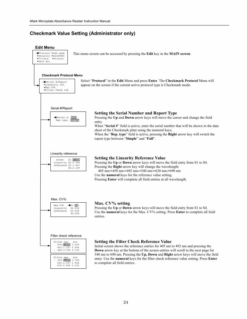
iMark Microplate Absorbance Reader Instruction Manual
25
Editing End Point Protocol
Upper Limit= 2000 Lower Limit= 0000 input range 0ndash3500 Upper gt Lower
Standard menu raquoSTD information
bullCurvefit bullRecall STD Curve
raquoCutoff bullMode bullReport bullMapping bullLimit bullKit name bullSTDs
Cutoff
See Plate Map setting procedure
See Standard setting procedure
See Mode setting procedure
raquo[Not use] bullRatio bullConstant bullContrl bullFormula
raquoSet photo mode bullSet shaking bullSet read mode
Select mapping mode raquoManual mapping bullAutomatic mapping
Mapping
Mode
Report
STDs
Limit
Kit name for 01 raquoGAP TEST IgGlaquo uarr [ABC]
Kit name See Kit name setting in Editing Kinetic Protocol
See Cutoff setting procedure
Select ldquoProtocolrdquo in Edit Menu screen above and press Enter The End point Protocol Menu will appear on the screen if the current active protocol type is End point mode
End Point Protocol Menu
raquo[Raw] bullMtx bullCnc bullAbs bullCut bullDif bullLim bullCrv
If ldquoDifrdquo selected
[Raw] bullMtx bullCncbullAbs bullCut [Dif] bullLim bullCrv raquorow odd-even
Seting the Report Type Use the Up and Down Arrow key to move the cursor and press the Right Arrow key to select or deselect the report type Selected report type is marked as ldquo[ ]rdquo Press Enter to complete the selection
Setting the Limit Value Use the Up and Down Arrow key to move the cursor and enter the OD value using the numeral keys The OD value range is 0000 - 3500 Press Enter to complete the selection
Edit Menu raquoProtocol bullLabname bullSecurity bullSaveSTDC bullFilters bullPrinter bullDate set
This menu screen can be accessed by pressing the Edit key in the MAIN screen
iMark Microplate Absorbance Reader Instruction Manual
26
Cutoff Setting Procedure
Cutoff Setting Menu This menu is entered by choosing Cutoff in the End Point Protocol Menu It is used to set the cutoff type The cutoff type marked with ldquo[ ]rdquo is the current selection The Up and Down arrow keys move the cursor to the desired item in the menu list When the desired parameters have been selected press Enter twice to accept the selection and to continue to the next screen Not use means that the reader does not generate the cutoff report Four types of cutoff are supported
1 Cutoff Constant 2 Cutoff Control 3 Cutoff Formula 4 Cutoff Ratio
a Cutoff Constant
Selection of SingleRanged Cutoff Constant This menu selects Single or Ranged cutoff type The cutoff type marked with ldquo[ ]rdquo is the current selection The Enter key seals the selection and resumes to the next setting screen
Single Cutoff Constant The Numerical keys and the Decimal point key are used to enter the positive and gray zone values The Right arrow key is used to select the unit The Up and Down arrow keys move the cursor to the desired parameter of the single cutoff The Enter key sets all values and selection of the cutoff constant and returns the user to the previous screen Ranged Cutoff Constant The Numerical keys and the Decimal point key are used to enter the positive and negative values The Right arrow key is used to select the unit The Up and Down arrow key moves the cursor to the desired ranged cutoff parameters The Enter key sets all values and selection of the cutoff constant and returns to the previous screen NOTE Two available Cutoff constants are ldquoAbsorbancerdquo and ldquoConcentrationrdquo If Abs is chosen the Absorbance cutoff will be done with the cutoff constant parameters defined and the absorbance report is generated For other units defined in the curve fit setting the Concentration value using the curve fit and then cutoff is done with the cutoff constant parameters defined and the concentration value of each well It is necessary to set the curve fit parameters
raquoNot usex bullRatio [Const] bullContrl bullFormula
raquoPositive gt= 9999 Gray zone 50 Unit moll
raquoPositive gt= 9999 Negative lt 1999 NegativeltPositive Unit moll
raquoRanged cutoff [Single cutoff]
Single cutoff
Ranged
iMark Microplate Absorbance Reader Instruction Manual
27
b Cutoff Control
Selection of SingleRanged Cutoff Control This menu screen selects Single or Ranged cutoff type The cutoff type marked with ldquo[ ]rdquo is the current selection The Enter key seals the selection and resumes to the next setting screen
Single Cutoff Control The Numerical keys are used to enter the gray zone value The unit is fixed to Abs The Enter key sets the value of the cutoff control and returns to the previous screen Ranged Cutoff Control There is no parameter to set for the ranged cutoff control The Enter key returns to the previous screen NOTE CNx is the mean absorbance value of Negative control wells and CPx is the mean absorbance value of Positive control wells These wells are defined in the plate map setting The cutoff is done with the Positive and Negative value to the absorbance value of each well
c Cutoff Formula
Selection of Formula This menu screen selects a formula for cutoff calculation The formula marked with ldquo[ ]rdquo is the current selection The Up and Down arrow keys move the cursor to the desired formula type The movement of the cursor follows the scroll of this screen The Enter key marks the selection and advances the user to the next setting screen The supported formula types are
1 k CNx 2 k CPx 3 k COx 4 CNx k 5 CPx k 6 COx k 7 k + CNx 8 k + CPx 9 k + COx 10 kCNx + CPx 11 ( CNx + CPx ) k 12 k1CNx + k2CPx
Coefficient for Cutoff Formula 1 to 11 The Numerical keys and the Decimal point key are used to enter the coefficient k and gray zone values The Up and Down arrow key moves the cursor to the desired parameter of the cutoff formula The Enter key sets all values of the cutoff formula and returns to the previous screen
Positive gt= CNx Gray zone 50 Unit Abs
Positive gt= CPx Negative lt CNx Unit Abs
Enter key to accept
raquoRanged cutoff [Single cutoff]
Single cutoff
Ranged
Input coefficient k = 001 (001-10) Gray zone 50(0-99)
k CNx k CPx k COx CNx k CPx k COx k k + CNx k + CPx k + COx k CNx + CPx (CNx + CPx) k
uarr raquoCNx k bullCPx k bullCOx k darr bullk + CNx
Select formula raquo[kCNx ] bullkCPx darr bullkCOx
uarr raquok + CPx bullk + COx bullkCNx + CPx darr bull(CNx + CPx) k
uarr raquok1CNx + k2CPx
Page-1
Page-2
Page-3
Page-4
iMark Microplate Absorbance Reader Instruction Manual
28
Coefficient for Cutoff Formula 12 The Numerical keys and the Decimal point key are used to enter the coefficient k1 and k2 and gray zone values The Up and Down arrow key moves the cursor to the desired cutoff formula The Enter key sets the all values of the cutoff formula and returns to the previous screen NOTE CNx is the mean absorbance value of Negative control wells CPx is the mean absorbance value of Positive control wells and COx is the mean absorbance value of Cutoff control wells These wells are defined on the plate map setting The cutoff value is calculated using the defined formula with the defined values and coefficients
d Cutoff Ratio
Ratio to Calibrator In this screen there are three items for setting the ratio to calibrator The Up and Down arrow key moves the cursor to the desired item in the menu list The Enter key seals the selection and resumes to the next setting screen
Concentration of Calibrator The Numerical keys and the Decimal point key are used to enter the calibrator concentration value The Enter key sets the value and returns to the previous screen Unit of Calibrator Seventeen standard units are supported The unit marked with ldquo[ ]rdquo is the current selection The setting procedure is the same as the unit selection of Standards Cutoff Value Setting This menu screen selects Single or Ranged cutoff type The cutoff type marked with ldquo[ ]rdquo is the current selection The Enter key marks the selection and continues to the next setting screen Single Cutoff Control The Numerical keys are used to enter the Positive cutoff concentration value and gray zone value The Enter key sets these cutoff ratio values and returns to the previous screen Ranged Cutoff Control The Numerical keys are used to input the Positive and the Negative cutoff concentration values The Enter key sets these cutoff ratios and returns to the previous screen NOTE The calibrator concentration value is used to convert the absorbance value of each well into a concentration value The ratio of ConcentrationAbsorbance of Calibrator well is applied to the conversion The cutoff uses defined Positive and Negative values to the converted concentration value of each well
Input coefficient k1 = 001 (001-10) k2 = 100 (001-10) Gray zone 50(0-99)
k1 CNx + k2 CPx
Ratio to Calibrator raquoConcentration bullUnit bullCutoff value
Concentration 9999 unit moll
uarrraquo 01 ugdl 02 ngml 03[ pgml] darr 04 pmml
raquoPositive gt= 9999 Gray zone 50
Unit moll
raquoPositive gt= 9999 Negative lt 9999 NegativeltPositive
Unit moll
raquoRanged cutoff [Single cutoff]
Concentration
Unit
Cutoff value
Single cutoff
Ranged cutoff
iMark Microplate Absorbance Reader Instruction Manual
29
Standard Setting Procedure
Standard Curve Setting Menu This menu screen is entered by choosing STDs in the End Point Protocol Menu screen It is used to set the concentration data and the curve fit type for a standard curve or to recall a memorized standard curve The Up and Down arrow key moves the cursor to the desired item in the menu list The Enter key seals the selection and continues to the next setting screen
a STD Information Setting
STD Information In this screen there are three items for setting the concentration data of standards The Up and Down arrow keys move the cursor to the desired item in the menu list The Enter key seals the selection and continues to the next setting screen
Number of Standards The Numerical keys are used to enter the number of standards ldquo0rdquo means that the curve fit report is not used The Enter key sets the number and returns to the previous screen The maximum number of standards is 12 Concentration The Numerical keys and the Decimal point key are used to enter the concentration values of standards The Up and Down arrow keys move the cursor to the desired position The movement of the cursor also follows the scroll of this screen The Enter key sets all values of the concentration of standards and returns to the previous screen Unit Seventeen units are supported The unit marked with ldquo[ ]rdquo is the current selection The Up and Down arrow keys move the cursor to the desired unit type The movement of the cursor also follows the scroll of this screen Press Enter twice to select the unit type and to return to the previous screen The supported types of unit are
1 moll 11 pgml 2 m moll 12 Uml 3 u moll 13 IUml 4 n moll 14 uIUml 5 p moll 15 mIUml 6 mgl 16 EU 7 ngl 17 Arbit 8 pgl 9 ugdl 10 ngml
STD information raquoNumber of STD bullConcentration bullUnit
STD 1 0512 STD 2 1012 STD 3 1512 darr STD 4 2053
Standard menu raquoSTD information bullCurve fit bullRecall STD curve
Concentration
Number of STD
Number of STD = 05 (0 2ndash12)
uarrraquo 01 ugdl 02 ngml 03[ pgml] darr 04 pmml
Unit
iMark Microplate Absorbance Reader Instruction Manual
30
b Curve Fit Setting
Curve Fit In this screen there are two choices to set the curve fit The Up and Down arrow keys move the cursor to the desired item in the menu list The Enter key seals the selection and resumes to the next setting screen
Curve Fit Type 10 types of curve fit are supported as below The curve fit type marked with ldquo[ ]rdquo is the current selection The Up and Down arrow key moves the cursor to the desired curve fit type The movement of the cursor follows the scroll of this screen Press Enter twice to select the unit type and to return to the previous screen The supported curve fit types are
1 5P Logistic Rodbard 2 4P Logistic Rodbard 3 5P Logistic Cook-Wilkenson 4 4P Logistic Cook-Wilkenson 5 5P Exponential 6 Sigmoid Logistic 7 Linear regression 8 Quadratic regression 9 Cubic 10 Point To Point regression
Graph Axis Four types of graph are supported The curve fit type marked with ldquo[ ]rdquo is the current selection The Up and Down arrow keys move the cursor to the desired graph type Press Enter twice to select the unit type and to return to the previous screen The supported graph types are
1 Log - Log 2 Log - Linear 3 Linear - Log 4 Linear - Linear
uarr 5p logisticRodb raquo 4p logisticRodb [5p logisticCook] darr 4p logisticCook
raquo X-Log Y-Log [X-Log Y-Lin] X-Lin Y-Log X-Lin Y-Lin
Curve fit type
Graph axis
Curve fit setting raquoCurve fit type bullGraph axis
iMark Microplate Absorbance Reader Instruction Manual
31
c Recall STD Curve Setting
Recall Setting of Standard Curve In this screen there are two items for setting the Recall STD curve as below The Up and Down arrow keys move the cursor to the desired item in the menu list
1 Recall setting (YesNo) 2 Selecting the storage number of standard curves (1 -gt 5)
Recall Setting Move the cursor to the desired position using the Up Down or Right arrow keys Enter key accepts the setting and returns the user to the standard menu screen
Yes Recalling of the standard curve is active No Recalling of the standard curve is inactive
Storage Number Selection Five memories are selectable The vacant memory (marked with asterisks on the date and time field) is also selectable It is necessary to save a standard curve before using its protocol Move the cursor to the desired position using the Up and Down keys This setting screen consists of two parts The Right arrow key is used to switch the indication field between the date and time to the standard curve name Move the cursor to the desired position using the Up and Down keys The Enter key accepts the storage number and returns to the standard menu screen NOTE If the recall of standard curve is active (the recall setting is ldquoYesrdquo) the standard information setting and the curve fit setting will be invalidated and their setting screens will not open
Recall STD curve raquoRecall setting bullSelect STD curve
Recall setting raquoYes No
Recall setting
Select STD Curve raquo1160304 1125
2 darr 3150304 1030
Select STD Curve uarrraquo4
5
Select STD Curve raquo1 STD Curve 1
2 STD Curve 2 darr 3 STD Curve 3
Select STD Curve uarrraquo4 STD Curve 4
5 STD Curve 5
Select STD curve
Right arrow key
iMark Microplate Absorbance Reader Instruction Manual
32
Mode Setting Procedure
Mode Setting Menu This menu screen is entered by choosing the Mode in the End Point Protocol Menu screen or the Kinetic Protocol Menu screen It is used to set the plate reading conditions The Up and Down arrow keys move the cursor to the desired item in the menu list The Enter key seals the selection and resumes to the next setting screen
a Set Photo Mode
Photo Mode In this screen the user chooses Single or Dual wavelength measurement and assigns the measurement and reference (for dual wavelength measurement) filters The assignment of the reference filter appears for dual wavelength measurement The Up and Down arrow keys move the cursor to the desired parameter The Right arrow key chooses SingleDual wavelength measurement and selects the installed filter on the Filters of Edit Menu screen The Enter key seals the selection and returns to the previous screen
b Set Shaking
Shaking In this screen the user selectsdeselects shaking function sets the shaking strength and enters the shaking time A shaking time of 0s indicates no shaking The maximum shaking time is 999 seconds The Up and Down arrow key moves the cursor to the desired parameters The Right arrow key toggles between YesNo (SelectDeselect) shaking or selects strength LowMiddleHigh The Numerical keys are used to enter the shaking time The Enter key seals the selection and returns the user to the previous screen
c Set Read Mode
Read Mode In this screen the user chooses Fast or Step reading and also chooses Normal or Evaluation mode The ldquo[ ]rdquoindicates the current selection The Up and Down arrow key moves the cursor to the desired parameters The Right arrow key chooses FastStep speed or chooses NormalEval mode The Enter key seals the selection and returns to the previous screen The followings are the description of each read mode parameter Reading speed
Fast reading 6 secsingle wavelength reading 10 secdual wavelength reading
Step reading 15 secsingle wavelength reading 30 secdual wavelength reading
Reading mode
Normal mode Plate reading once Evaluation mode Four plate readings per one of measurement are performed and
the average data of their plate readings is generated as a plate data
Photometric Dual Measurement400 nm Reference 655 nm
Set Shake parameters ShakeYes SpeedMid Time 199sec(0-999)
raquoReading speed [Fast ] Step bullRead mode [Normal] Eval
raquoSet Photo mode bullSet shaking bullSet read mode
Photometric Single Measurement400 nm
iMark Microplate Absorbance Reader Instruction Manual
33
Plate Map Setting Procedure
Select Mapping Mode Menu This menu screen is entered by choosing Mapping in the End Point Protocol Menu screen or the Kinetic Protocol Menu screen It is used to map the plate format The Up and Down arrow keys move the cursor next to the desired item of menu list The Enter key seals the selection and changes this screen to the next setting screen
a Manual Mapping
Manual Mapping In this screen the user can set the plate format manually Ten well types can be set Well types The supported well types are
Well type Indication on LCD
1 Blank B 2 Sample X00hellipX99 3 Standard S01hellipS99 4 In-kit Control Positive Control CP0hellipCP9 5 Weak Positive Control CW0hellipCW9 6 Negative Control CN0hellipCN9 7 Cutoff Control CO0hellipCO9 8 Calibrator CL0hellipCL9 9 QC Control QC0hellipQC9 10 Empty well -
The key assignments of well type are ldquo0EMPrdquo Empty well ldquo5QCrdquo Quality Control well ldquo1SMPrdquo Sample well ldquo6CALrdquo Calibrator well ldquo2BLKrdquo Blank well ldquo7CPrdquo Positive Control well ldquo3STDrdquo Standard well ldquo8CNrdquo Negative Control well ldquo4COrdquo Cutoff Control well ldquo9CWrdquo Weak Positive Control well
Two Edit Modes in Plate Mapping There are two editing modes for well type input mode and for well number input The current input mode is displayed at the upper left corner of the screen When using the well type input mode the mode sign is ldquo[F]rdquo When using the well number input mode the mode sign is ldquoNrdquo The cursor that encloses the editing position of well has two types of enclosures depending on the mode For example ldquo[S01]rdquo accepts the well type keys that be assigned to the numerical keys and ldquoS01rdquo accepts the numerical input The mode is easily changed with the Decimal point key Key Functions The Up Down Right and Left arrow keys move the cursor to the desired well The movement of the cursor follows the scroll of this screen The Left arrow key will return the screen to the preceding screen or the select Mapping mode Menu only if the cursor is on column 1 At this time the selection screen appears (see the left figure) The Decimal point key changes the input mode The Numerical keys have two functions one to input the number and another to select a well type The Enter key checks the consistency between the edited plate map and other parameters memorizes the plate map into the protocol and changes this screen back to the preceding screen If it finds any inconsistency a warning message will appear on the screen
Select Mapping mode raquoManual mapping bullAutomatic mapping
N 1 2 3 4 A B CN1 S01 S01 B B CN1 S02 S02 C B CN2 S03 S03 [F] 5 6 7 8 A X11 X12 X13 X14 B X21 X22 X23 X24 C X31 X32 X33[X34]
Discard change 1Yes 2No Press 1 or 2 key
iMark Microplate Absorbance Reader Instruction Manual
34
Acceptable Number Ranges for each well type 1 Blank and Empty wells do not use numbers 2 Sample and Standard wells 00 - 99 3 Standard wells 01 - 99 4 Control and Calibrator wells 0 - 9
b Automatic Mapping
Automatic Mapping The user can input the number of each well type in this screen These defined numbers are used to set a plate map automatically Well type Nine well types are available
1 BLK Blank (0-gt10) 2 CN Control CN (0-gt9) 3 CW Control CW (0-gt9) 4 CP Control CP (0-gt9) 5 CO Control CO (0-gt9) 6 QC Control QC (0-gt9) 7 CAL Calibrator (0-gt9) 8 SMP Sample (0-gt96) 9 REP Replicate well (1-gt4)
It is possible to define the number of blanks samples calibrators and controls But the number of Standards is not included because standards are defined at the Standard Setting Menu The number of replicate wells is also included It is used for replicating each well type individually Key Functions The Up Down Right and Left arrow keys are used to move the cursor to the next position The Numerical keys are used to input the mapping parameters The Enter key accepts the mapping parameters and sets a plate map automatically using these parameters During the execution of the plate mapping the Plate auto-mapping completed message appears on the screen After that the user returns automatically to the previous Protocol Menu screen If the Left arrow key is pressed at the left end position of the cursor the left figure will appear on the screen If the user chooses Yes the system will return to the previous Protocol Menu screen If the user chooses No the system will stay in this setting screen Assigning Order and Direction of plate mapping Assigning Order The order of blanks standards samples calibrators and controls are fixed as follows Numbering for standards samples calibrators and controls is started at 1
1 Blank 2 Standard 1 -gt12 ---- NOTE 3 Control CN 1-gt9 4 Control CW 1-gt9 5 Control CP 1-gt9 6 Control CO 1-gt9 7 Control QC 1-gt9 8 Calibrator 1-gt9 9 Sample 1-gt96 10 Empty well NOTE If ldquoCutoff Controlrdquo ldquoValue by Formulardquo or ldquoRatio to Calibratorrdquo is
selected for the Cutoff plate mapping skips arranging the standards Assigning Direction The placing direction of the mapping is limited to the column direction as below
Column direction A1 -gt H1 A2 -gt H2 ----- A12 -gt H12
Discard change 1Yes 2No Press 1 or 2 key
Automatic mapping BLK= 1 CP = 1 CAL= 0 CN = 1 CO = 0 SMP=93 CW = 0 QC = 0 REP= 1
Plate auto-mapping completed
iMark Microplate Absorbance Reader Instruction Manual
35
Warning and Error of Automatic Mapping Warning screen If the total number of wells mapped exceeds 96 wells a warning message in the left figure appears on the screen The calculation of the total number of mapping wells is as follows
(Blanks+Standards+CNs+CWs+CPs+COs+QCs+Calibrators+Sample)Replicates The plate mapping is executed normally and the exceeded part is invalidated Error screen If one or more mapping parameters are over the input range an error message in the left figure will appear on the screen On the third line of the LCD the name of the parameter which is out of range and its input range will appear
Example ldquoBLK 0 ndash 10rdquo In case there is more than one error the first parameter of errors is indicated By pressing any key the user returns to the automatic mapping screen Example of automatic mapping An example of automatic mapping is as below 1 Conditions of each parameter
Blank = 1 Standard = 8 Control CN = 2 CW = 0 CP = 2 CO = 0 QC = 0 Calibrator = 1 Sample = 32 Replicate number = 2
2 Plate mapping data
1 2 3 4 5 6 7 8 9 10 11 12 A B C D E F G H
B B S1 S1 S2 S2 S3 S3
S4 S4 S5 S5 S6 S6 S7 S7
S8 S8 CN1 CN1 CN2 CN2 CP1 CP1
CP2 CP2 CL1 CL1 X1 X1 X2 X2
X3 X3 X4 X4 X5 X5 X6 X6
X7 X7 X8 X8 X9 X9 X10 X10
X11 X11 X12 X12 X13 X13 X14 X14
X15 X15 X16 X16 X17 X17 X18 X18
X19 X19 X20 X20 X21 X21 X22 X22
X23 X23 X24 X24 X25 X25 X26 X26
X27 X27 X28 X28 X29 X29 X30 X30
X31 X31 X32 X32 E E E E
Warning The total Of mapped wells has Exceeded 96 Press any key
Entered value is Out of range BLK 0 ndash 10 Press any key
iMark Microplate Absorbance Reader Instruction Manual
36
Instrument Maintenance
Caution Electrical shock hazard Always disconnect the instrument from the AC power source before opening the service compartment
Caution The lamp and the lamp cover may be very hot Use caution and allow the lamp to cool
before attempting service
Installing Interference Filters 1 With the power off open the rear cover of the instrument by pressing the
release latch located on the top left portion of the cover 2 Locate the filter wheel on the left side of the instrument Note that the
filter wheel has eight filter positions 3 Rotate the filter wheel to the desired filter Grasp the top of filter frame
and pull up to remove the filter 4 Insert the new filter into the desired filter position 5 Ensure that the new filter is added to the filter list as follows Main
menu-gtEdit-gtFilters
Changing the Lamp 1 With the power off open the rear cover of the instrument by pressing the
release latch located on the top left portion of the cover 2 Remove the two screws on the black plastic cover and carefully remove
the plastic cover 3 Remove the screw on the metal cover Lift the cover up and away from
the instrument This will allow the lamp to be pulled free from the lamp housing
4 Holding the ceramic base in one hand and the lamp housing in the other carefully pull the lamp free of the base
5 Carefully insert the new lamp firmly in the ceramic base Apply even pressure when inserting the lamp so that the bulb dose not become misaligned in the reflector housing Be extremely careful not to touch the front glass of the lamp during installation
6 Position the new lamp into the housing so that the plastic guides hold the flange of the lamp
7 Carefully place the metal cover over the lamp Tighten the screw 8 Replace the plastic cover and tighten the screws 9 Close the rear cover
iMark Microplate Absorbance Reader Instruction Manual
37
Troubleshooting and Error Messages
The iMark Microplate Reader constantly monitors several functions and displays appropriate messages on the LCD as errors are encountered
Error Recommendation
LCD appears blank on power up
a Power is not turned on The AC outlet is non-functional
b Unit is not plugged into AC outlet or power code is not attached to the instrument
Check power cord connections at outlet and on the rear panel of the instrument
1
c The AC outlet is non-functional Check circuit breakers or fuses
Instrument displays ldquoLight bulb errorrdquo message indicating that the bulb is burned out
Check whether lamp is emitting light
a Lamp is not emitting light Replace the lamp as described in x
2
b Lamp is emitting light Check the alignment of the lamp in the housing Align or replace the lamp if necessary
Printer will not print on command
3
a Printer paper is not installed properly Verify that the paper is properly installed Refer to x for details
Plate carriage jams during reading and ldquoPlate carrier errorrdquo is displayed
a Plate is not seated in carriage properly Press the STOP button immediately Position the plate carefully in the carriage making certain that it is properly seated
4
b Plate height is exceeding 16mm Use Microplate which is less than 16mm in height
5 LCD displays ldquoFilter missingrdquo Install a filter in the empty position Select the installed filter by pressing Edit key
6 LCD displays ldquoFilter disk jammedrdquo indicating that the filter wheel is not turning freely
Turn off the instrument and inspect the filter wheel Turn by hand to verify that the wheel is moving freely Make sure all the filters are properly installed and firmly seated Contact your Bio-Rad representative if the filter wheel is jammed or if the problem persists
7 LCD displays ldquoFilter not installedrdquo Enter the Edit Menu by pressing Edit key and set up the filters
iMark Microplate Absorbance Reader Instruction Manual
38
Wells have color but absorbance values seem low
a Incorrect filter used for measurement andor reference wavelength
Check wavelength used in analysis Read plate in single wavelength mode at all wavelength to verify that the proper filter was used The measurement wavelength should produce the highest absorbance
b The best measurement wavelength filter for the substrate in use has not been installed in the filter wheel
Check references for the substrate you are using or determine the best measurement wavelength by analyzing the substrate product on a scanning spectrophotometer Custom filters are available from 400 to 750 nm
8
c The filters have been switched in the wheel Check that the filters are installed in the correct position
9 ldquoPrinter errorrdquo displayed Check for paper jam Install the printer paper correctly
10 ldquoBattery errorrdquo displayed The internal battery is almost dead Contact your local Bio-Rad office
11 The following messages are displayed ldquoMemory errorrdquo ldquoCalendar errorrdquo ldquoLCD hardware errorrdquo ldquoPrinter errorrdquo ldquoLight level errorrdquo ldquoDA conversion errorrdquo ldquoAD conversion errorrdquo ldquoEEPROM errorrdquo ldquoUSB errorrdquo
Contact your local Bio-Rad office if these problems persist
iMark Microplate Absorbance Reader Instruction Manual
39
Instrument Specifications Computer interface USB 20
Plate shaking 3 speeds (low mid high) Programmable time period 0 - 999 seconds
Data storage The most recent 10 data plates for end-point most recent 2 data plates of 30 readings for kinetic readings protocol data and calendarclock function shall be kept in memory by a lithium battery even when the power is off Average lifetime of the battery shall be 5 years
Warm-up time 3 minutes
Photometric Methods Single and dual wavelength
Photo detectors 8 silicon photodiodes for measurement and 1 silicon photodiode for reference
Light source Tungsten halogen lamp 20W with 3000 hours average lifetime
Spectral range 400 nm to 750 nm
Interference filters Wavelength tolerance plusmn30 nm Band width 10 nm typically
Filter capacity 8 filters
Reading speed Fast Reading 6 sec with single wavelength reading 10 sec with dual wavelength reading
Step Reading 15 sec with single wavelength reading 25 sec with dual wavelength reading
These times are minimum interval times between repetitive reads using onboard KINETIC protocol
Indication range 0000 to 35 OD
Resolution 0001 OD
Accuracy plusmn10 or 0010 from 0 to 30 OD at 490 nm
Linearity plusmn10 from 0 to 20 OD plusmn20 from 0 to 30 OD
Reproducibility 10 or 0005 OD from 0 to 20 OD 15 from 20 to 30 OD
Inter-channel variability 15 or 0005 OD from 0 to 30 OD
Stability and Drift 0010 OD at OD=1 with single wavelength reading
Built-in Printer Thermal printer Paper width 80mm
Line Voltage Universal input 100 - 240 VAC 5060Hz
Power consumption (max) 100 VA max
Dimensions (W x D x H 346 mm x 377 mm x 164 m mm
Weight 55 kg
Operating Environment 15ordmC - 40ordmC up to 90 relative humidity without condensation
Storage Temperature 10ordmC - 50ordmC up to 90 relative humidity without condensation
Life ScienceGroup
07-0816 0108 Sig 120710013301i Rev A USEG
Bio-RadLaboratories Inc
Web site wwwbio-radcom USA 800 4BIORAD Australia 61 02 9914 2800 Austria 01 877 89 01 Belgium 09 385 55 11 Brazil 55 21 3237 9400 Canada 905 364 3435 China 86 21 6426 0808 Czech Republic 420 241 430 532 Denmark 44 52 10 00 Finland 09 804 22 00 France 01 47 95 69 65Germany 089 318 84 0 Greece 30 210 777 4396 Hong Kong 852 2789 3300 Hungary 36 1 455 8800 India 91 124 4029300 Israel 03 963 6050 Italy 39 02 216091 Japan 03 6361 7000 Korea 82 2 3473 4460 Mexico 52 555 488 7670 The Netherlands 0318 540666 New Zealand 0508 805 500 Norway 23 38 41 30 Poland 48 22 331 99 99 Portugal 351 21 472 7700 Russia 7 495 721 14 04 Singapore 65 6415 3188 South Africa 27 861 246 723 Spain 34 91 590 5200 Sweden 08 555 12700 Switzerland 061 717 95 55 Taiwan 886 2 2578 7189 United Kingdom 020 8328 2000
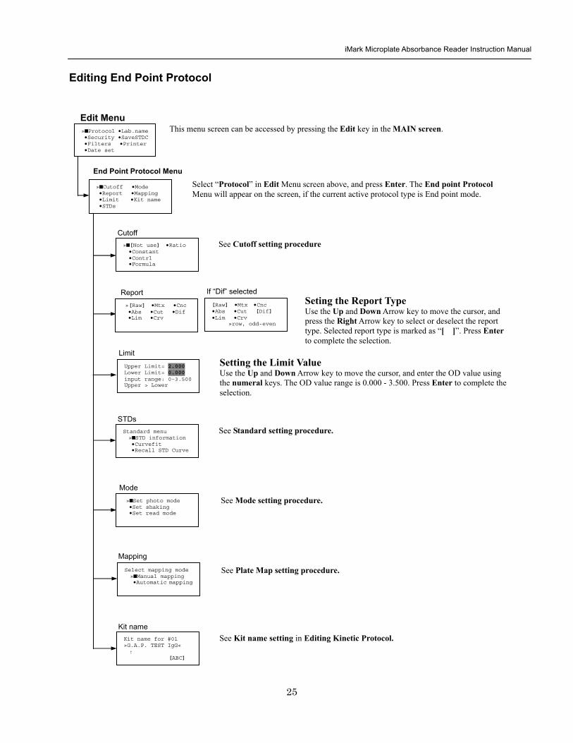
iMark Microplate Absorbance Reader Instruction Manual
26
Cutoff Setting Procedure
Cutoff Setting Menu This menu is entered by choosing Cutoff in the End Point Protocol Menu It is used to set the cutoff type The cutoff type marked with ldquo[ ]rdquo is the current selection The Up and Down arrow keys move the cursor to the desired item in the menu list When the desired parameters have been selected press Enter twice to accept the selection and to continue to the next screen Not use means that the reader does not generate the cutoff report Four types of cutoff are supported
1 Cutoff Constant 2 Cutoff Control 3 Cutoff Formula 4 Cutoff Ratio
a Cutoff Constant
Selection of SingleRanged Cutoff Constant This menu selects Single or Ranged cutoff type The cutoff type marked with ldquo[ ]rdquo is the current selection The Enter key seals the selection and resumes to the next setting screen
Single Cutoff Constant The Numerical keys and the Decimal point key are used to enter the positive and gray zone values The Right arrow key is used to select the unit The Up and Down arrow keys move the cursor to the desired parameter of the single cutoff The Enter key sets all values and selection of the cutoff constant and returns the user to the previous screen Ranged Cutoff Constant The Numerical keys and the Decimal point key are used to enter the positive and negative values The Right arrow key is used to select the unit The Up and Down arrow key moves the cursor to the desired ranged cutoff parameters The Enter key sets all values and selection of the cutoff constant and returns to the previous screen NOTE Two available Cutoff constants are ldquoAbsorbancerdquo and ldquoConcentrationrdquo If Abs is chosen the Absorbance cutoff will be done with the cutoff constant parameters defined and the absorbance report is generated For other units defined in the curve fit setting the Concentration value using the curve fit and then cutoff is done with the cutoff constant parameters defined and the concentration value of each well It is necessary to set the curve fit parameters
raquoNot usex bullRatio [Const] bullContrl bullFormula
raquoPositive gt= 9999 Gray zone 50 Unit moll
raquoPositive gt= 9999 Negative lt 1999 NegativeltPositive Unit moll
raquoRanged cutoff [Single cutoff]
Single cutoff
Ranged
iMark Microplate Absorbance Reader Instruction Manual
27
b Cutoff Control
Selection of SingleRanged Cutoff Control This menu screen selects Single or Ranged cutoff type The cutoff type marked with ldquo[ ]rdquo is the current selection The Enter key seals the selection and resumes to the next setting screen
Single Cutoff Control The Numerical keys are used to enter the gray zone value The unit is fixed to Abs The Enter key sets the value of the cutoff control and returns to the previous screen Ranged Cutoff Control There is no parameter to set for the ranged cutoff control The Enter key returns to the previous screen NOTE CNx is the mean absorbance value of Negative control wells and CPx is the mean absorbance value of Positive control wells These wells are defined in the plate map setting The cutoff is done with the Positive and Negative value to the absorbance value of each well
c Cutoff Formula
Selection of Formula This menu screen selects a formula for cutoff calculation The formula marked with ldquo[ ]rdquo is the current selection The Up and Down arrow keys move the cursor to the desired formula type The movement of the cursor follows the scroll of this screen The Enter key marks the selection and advances the user to the next setting screen The supported formula types are
1 k CNx 2 k CPx 3 k COx 4 CNx k 5 CPx k 6 COx k 7 k + CNx 8 k + CPx 9 k + COx 10 kCNx + CPx 11 ( CNx + CPx ) k 12 k1CNx + k2CPx
Coefficient for Cutoff Formula 1 to 11 The Numerical keys and the Decimal point key are used to enter the coefficient k and gray zone values The Up and Down arrow key moves the cursor to the desired parameter of the cutoff formula The Enter key sets all values of the cutoff formula and returns to the previous screen
Positive gt= CNx Gray zone 50 Unit Abs
Positive gt= CPx Negative lt CNx Unit Abs
Enter key to accept
raquoRanged cutoff [Single cutoff]
Single cutoff
Ranged
Input coefficient k = 001 (001-10) Gray zone 50(0-99)
k CNx k CPx k COx CNx k CPx k COx k k + CNx k + CPx k + COx k CNx + CPx (CNx + CPx) k
uarr raquoCNx k bullCPx k bullCOx k darr bullk + CNx
Select formula raquo[kCNx ] bullkCPx darr bullkCOx
uarr raquok + CPx bullk + COx bullkCNx + CPx darr bull(CNx + CPx) k
uarr raquok1CNx + k2CPx
Page-1
Page-2
Page-3
Page-4
iMark Microplate Absorbance Reader Instruction Manual
28
Coefficient for Cutoff Formula 12 The Numerical keys and the Decimal point key are used to enter the coefficient k1 and k2 and gray zone values The Up and Down arrow key moves the cursor to the desired cutoff formula The Enter key sets the all values of the cutoff formula and returns to the previous screen NOTE CNx is the mean absorbance value of Negative control wells CPx is the mean absorbance value of Positive control wells and COx is the mean absorbance value of Cutoff control wells These wells are defined on the plate map setting The cutoff value is calculated using the defined formula with the defined values and coefficients
d Cutoff Ratio
Ratio to Calibrator In this screen there are three items for setting the ratio to calibrator The Up and Down arrow key moves the cursor to the desired item in the menu list The Enter key seals the selection and resumes to the next setting screen
Concentration of Calibrator The Numerical keys and the Decimal point key are used to enter the calibrator concentration value The Enter key sets the value and returns to the previous screen Unit of Calibrator Seventeen standard units are supported The unit marked with ldquo[ ]rdquo is the current selection The setting procedure is the same as the unit selection of Standards Cutoff Value Setting This menu screen selects Single or Ranged cutoff type The cutoff type marked with ldquo[ ]rdquo is the current selection The Enter key marks the selection and continues to the next setting screen Single Cutoff Control The Numerical keys are used to enter the Positive cutoff concentration value and gray zone value The Enter key sets these cutoff ratio values and returns to the previous screen Ranged Cutoff Control The Numerical keys are used to input the Positive and the Negative cutoff concentration values The Enter key sets these cutoff ratios and returns to the previous screen NOTE The calibrator concentration value is used to convert the absorbance value of each well into a concentration value The ratio of ConcentrationAbsorbance of Calibrator well is applied to the conversion The cutoff uses defined Positive and Negative values to the converted concentration value of each well
Input coefficient k1 = 001 (001-10) k2 = 100 (001-10) Gray zone 50(0-99)
k1 CNx + k2 CPx
Ratio to Calibrator raquoConcentration bullUnit bullCutoff value
Concentration 9999 unit moll
uarrraquo 01 ugdl 02 ngml 03[ pgml] darr 04 pmml
raquoPositive gt= 9999 Gray zone 50
Unit moll
raquoPositive gt= 9999 Negative lt 9999 NegativeltPositive
Unit moll
raquoRanged cutoff [Single cutoff]
Concentration
Unit
Cutoff value
Single cutoff
Ranged cutoff
iMark Microplate Absorbance Reader Instruction Manual
29
Standard Setting Procedure
Standard Curve Setting Menu This menu screen is entered by choosing STDs in the End Point Protocol Menu screen It is used to set the concentration data and the curve fit type for a standard curve or to recall a memorized standard curve The Up and Down arrow key moves the cursor to the desired item in the menu list The Enter key seals the selection and continues to the next setting screen
a STD Information Setting
STD Information In this screen there are three items for setting the concentration data of standards The Up and Down arrow keys move the cursor to the desired item in the menu list The Enter key seals the selection and continues to the next setting screen
Number of Standards The Numerical keys are used to enter the number of standards ldquo0rdquo means that the curve fit report is not used The Enter key sets the number and returns to the previous screen The maximum number of standards is 12 Concentration The Numerical keys and the Decimal point key are used to enter the concentration values of standards The Up and Down arrow keys move the cursor to the desired position The movement of the cursor also follows the scroll of this screen The Enter key sets all values of the concentration of standards and returns to the previous screen Unit Seventeen units are supported The unit marked with ldquo[ ]rdquo is the current selection The Up and Down arrow keys move the cursor to the desired unit type The movement of the cursor also follows the scroll of this screen Press Enter twice to select the unit type and to return to the previous screen The supported types of unit are
1 moll 11 pgml 2 m moll 12 Uml 3 u moll 13 IUml 4 n moll 14 uIUml 5 p moll 15 mIUml 6 mgl 16 EU 7 ngl 17 Arbit 8 pgl 9 ugdl 10 ngml
STD information raquoNumber of STD bullConcentration bullUnit
STD 1 0512 STD 2 1012 STD 3 1512 darr STD 4 2053
Standard menu raquoSTD information bullCurve fit bullRecall STD curve
Concentration
Number of STD
Number of STD = 05 (0 2ndash12)
uarrraquo 01 ugdl 02 ngml 03[ pgml] darr 04 pmml
Unit
iMark Microplate Absorbance Reader Instruction Manual
30
b Curve Fit Setting
Curve Fit In this screen there are two choices to set the curve fit The Up and Down arrow keys move the cursor to the desired item in the menu list The Enter key seals the selection and resumes to the next setting screen
Curve Fit Type 10 types of curve fit are supported as below The curve fit type marked with ldquo[ ]rdquo is the current selection The Up and Down arrow key moves the cursor to the desired curve fit type The movement of the cursor follows the scroll of this screen Press Enter twice to select the unit type and to return to the previous screen The supported curve fit types are
1 5P Logistic Rodbard 2 4P Logistic Rodbard 3 5P Logistic Cook-Wilkenson 4 4P Logistic Cook-Wilkenson 5 5P Exponential 6 Sigmoid Logistic 7 Linear regression 8 Quadratic regression 9 Cubic 10 Point To Point regression
Graph Axis Four types of graph are supported The curve fit type marked with ldquo[ ]rdquo is the current selection The Up and Down arrow keys move the cursor to the desired graph type Press Enter twice to select the unit type and to return to the previous screen The supported graph types are
1 Log - Log 2 Log - Linear 3 Linear - Log 4 Linear - Linear
uarr 5p logisticRodb raquo 4p logisticRodb [5p logisticCook] darr 4p logisticCook
raquo X-Log Y-Log [X-Log Y-Lin] X-Lin Y-Log X-Lin Y-Lin
Curve fit type
Graph axis
Curve fit setting raquoCurve fit type bullGraph axis
iMark Microplate Absorbance Reader Instruction Manual
31
c Recall STD Curve Setting
Recall Setting of Standard Curve In this screen there are two items for setting the Recall STD curve as below The Up and Down arrow keys move the cursor to the desired item in the menu list
1 Recall setting (YesNo) 2 Selecting the storage number of standard curves (1 -gt 5)
Recall Setting Move the cursor to the desired position using the Up Down or Right arrow keys Enter key accepts the setting and returns the user to the standard menu screen
Yes Recalling of the standard curve is active No Recalling of the standard curve is inactive
Storage Number Selection Five memories are selectable The vacant memory (marked with asterisks on the date and time field) is also selectable It is necessary to save a standard curve before using its protocol Move the cursor to the desired position using the Up and Down keys This setting screen consists of two parts The Right arrow key is used to switch the indication field between the date and time to the standard curve name Move the cursor to the desired position using the Up and Down keys The Enter key accepts the storage number and returns to the standard menu screen NOTE If the recall of standard curve is active (the recall setting is ldquoYesrdquo) the standard information setting and the curve fit setting will be invalidated and their setting screens will not open
Recall STD curve raquoRecall setting bullSelect STD curve
Recall setting raquoYes No
Recall setting
Select STD Curve raquo1160304 1125
2 darr 3150304 1030
Select STD Curve uarrraquo4
5
Select STD Curve raquo1 STD Curve 1
2 STD Curve 2 darr 3 STD Curve 3
Select STD Curve uarrraquo4 STD Curve 4
5 STD Curve 5
Select STD curve
Right arrow key
iMark Microplate Absorbance Reader Instruction Manual
32
Mode Setting Procedure
Mode Setting Menu This menu screen is entered by choosing the Mode in the End Point Protocol Menu screen or the Kinetic Protocol Menu screen It is used to set the plate reading conditions The Up and Down arrow keys move the cursor to the desired item in the menu list The Enter key seals the selection and resumes to the next setting screen
a Set Photo Mode
Photo Mode In this screen the user chooses Single or Dual wavelength measurement and assigns the measurement and reference (for dual wavelength measurement) filters The assignment of the reference filter appears for dual wavelength measurement The Up and Down arrow keys move the cursor to the desired parameter The Right arrow key chooses SingleDual wavelength measurement and selects the installed filter on the Filters of Edit Menu screen The Enter key seals the selection and returns to the previous screen
b Set Shaking
Shaking In this screen the user selectsdeselects shaking function sets the shaking strength and enters the shaking time A shaking time of 0s indicates no shaking The maximum shaking time is 999 seconds The Up and Down arrow key moves the cursor to the desired parameters The Right arrow key toggles between YesNo (SelectDeselect) shaking or selects strength LowMiddleHigh The Numerical keys are used to enter the shaking time The Enter key seals the selection and returns the user to the previous screen
c Set Read Mode
Read Mode In this screen the user chooses Fast or Step reading and also chooses Normal or Evaluation mode The ldquo[ ]rdquoindicates the current selection The Up and Down arrow key moves the cursor to the desired parameters The Right arrow key chooses FastStep speed or chooses NormalEval mode The Enter key seals the selection and returns to the previous screen The followings are the description of each read mode parameter Reading speed
Fast reading 6 secsingle wavelength reading 10 secdual wavelength reading
Step reading 15 secsingle wavelength reading 30 secdual wavelength reading
Reading mode
Normal mode Plate reading once Evaluation mode Four plate readings per one of measurement are performed and
the average data of their plate readings is generated as a plate data
Photometric Dual Measurement400 nm Reference 655 nm
Set Shake parameters ShakeYes SpeedMid Time 199sec(0-999)
raquoReading speed [Fast ] Step bullRead mode [Normal] Eval
raquoSet Photo mode bullSet shaking bullSet read mode
Photometric Single Measurement400 nm
iMark Microplate Absorbance Reader Instruction Manual
33
Plate Map Setting Procedure
Select Mapping Mode Menu This menu screen is entered by choosing Mapping in the End Point Protocol Menu screen or the Kinetic Protocol Menu screen It is used to map the plate format The Up and Down arrow keys move the cursor next to the desired item of menu list The Enter key seals the selection and changes this screen to the next setting screen
a Manual Mapping
Manual Mapping In this screen the user can set the plate format manually Ten well types can be set Well types The supported well types are
Well type Indication on LCD
1 Blank B 2 Sample X00hellipX99 3 Standard S01hellipS99 4 In-kit Control Positive Control CP0hellipCP9 5 Weak Positive Control CW0hellipCW9 6 Negative Control CN0hellipCN9 7 Cutoff Control CO0hellipCO9 8 Calibrator CL0hellipCL9 9 QC Control QC0hellipQC9 10 Empty well -
The key assignments of well type are ldquo0EMPrdquo Empty well ldquo5QCrdquo Quality Control well ldquo1SMPrdquo Sample well ldquo6CALrdquo Calibrator well ldquo2BLKrdquo Blank well ldquo7CPrdquo Positive Control well ldquo3STDrdquo Standard well ldquo8CNrdquo Negative Control well ldquo4COrdquo Cutoff Control well ldquo9CWrdquo Weak Positive Control well
Two Edit Modes in Plate Mapping There are two editing modes for well type input mode and for well number input The current input mode is displayed at the upper left corner of the screen When using the well type input mode the mode sign is ldquo[F]rdquo When using the well number input mode the mode sign is ldquoNrdquo The cursor that encloses the editing position of well has two types of enclosures depending on the mode For example ldquo[S01]rdquo accepts the well type keys that be assigned to the numerical keys and ldquoS01rdquo accepts the numerical input The mode is easily changed with the Decimal point key Key Functions The Up Down Right and Left arrow keys move the cursor to the desired well The movement of the cursor follows the scroll of this screen The Left arrow key will return the screen to the preceding screen or the select Mapping mode Menu only if the cursor is on column 1 At this time the selection screen appears (see the left figure) The Decimal point key changes the input mode The Numerical keys have two functions one to input the number and another to select a well type The Enter key checks the consistency between the edited plate map and other parameters memorizes the plate map into the protocol and changes this screen back to the preceding screen If it finds any inconsistency a warning message will appear on the screen
Select Mapping mode raquoManual mapping bullAutomatic mapping
N 1 2 3 4 A B CN1 S01 S01 B B CN1 S02 S02 C B CN2 S03 S03 [F] 5 6 7 8 A X11 X12 X13 X14 B X21 X22 X23 X24 C X31 X32 X33[X34]
Discard change 1Yes 2No Press 1 or 2 key
iMark Microplate Absorbance Reader Instruction Manual
34
Acceptable Number Ranges for each well type 1 Blank and Empty wells do not use numbers 2 Sample and Standard wells 00 - 99 3 Standard wells 01 - 99 4 Control and Calibrator wells 0 - 9
b Automatic Mapping
Automatic Mapping The user can input the number of each well type in this screen These defined numbers are used to set a plate map automatically Well type Nine well types are available
1 BLK Blank (0-gt10) 2 CN Control CN (0-gt9) 3 CW Control CW (0-gt9) 4 CP Control CP (0-gt9) 5 CO Control CO (0-gt9) 6 QC Control QC (0-gt9) 7 CAL Calibrator (0-gt9) 8 SMP Sample (0-gt96) 9 REP Replicate well (1-gt4)
It is possible to define the number of blanks samples calibrators and controls But the number of Standards is not included because standards are defined at the Standard Setting Menu The number of replicate wells is also included It is used for replicating each well type individually Key Functions The Up Down Right and Left arrow keys are used to move the cursor to the next position The Numerical keys are used to input the mapping parameters The Enter key accepts the mapping parameters and sets a plate map automatically using these parameters During the execution of the plate mapping the Plate auto-mapping completed message appears on the screen After that the user returns automatically to the previous Protocol Menu screen If the Left arrow key is pressed at the left end position of the cursor the left figure will appear on the screen If the user chooses Yes the system will return to the previous Protocol Menu screen If the user chooses No the system will stay in this setting screen Assigning Order and Direction of plate mapping Assigning Order The order of blanks standards samples calibrators and controls are fixed as follows Numbering for standards samples calibrators and controls is started at 1
1 Blank 2 Standard 1 -gt12 ---- NOTE 3 Control CN 1-gt9 4 Control CW 1-gt9 5 Control CP 1-gt9 6 Control CO 1-gt9 7 Control QC 1-gt9 8 Calibrator 1-gt9 9 Sample 1-gt96 10 Empty well NOTE If ldquoCutoff Controlrdquo ldquoValue by Formulardquo or ldquoRatio to Calibratorrdquo is
selected for the Cutoff plate mapping skips arranging the standards Assigning Direction The placing direction of the mapping is limited to the column direction as below
Column direction A1 -gt H1 A2 -gt H2 ----- A12 -gt H12
Discard change 1Yes 2No Press 1 or 2 key
Automatic mapping BLK= 1 CP = 1 CAL= 0 CN = 1 CO = 0 SMP=93 CW = 0 QC = 0 REP= 1
Plate auto-mapping completed
iMark Microplate Absorbance Reader Instruction Manual
35
Warning and Error of Automatic Mapping Warning screen If the total number of wells mapped exceeds 96 wells a warning message in the left figure appears on the screen The calculation of the total number of mapping wells is as follows
(Blanks+Standards+CNs+CWs+CPs+COs+QCs+Calibrators+Sample)Replicates The plate mapping is executed normally and the exceeded part is invalidated Error screen If one or more mapping parameters are over the input range an error message in the left figure will appear on the screen On the third line of the LCD the name of the parameter which is out of range and its input range will appear
Example ldquoBLK 0 ndash 10rdquo In case there is more than one error the first parameter of errors is indicated By pressing any key the user returns to the automatic mapping screen Example of automatic mapping An example of automatic mapping is as below 1 Conditions of each parameter
Blank = 1 Standard = 8 Control CN = 2 CW = 0 CP = 2 CO = 0 QC = 0 Calibrator = 1 Sample = 32 Replicate number = 2
2 Plate mapping data
1 2 3 4 5 6 7 8 9 10 11 12 A B C D E F G H
B B S1 S1 S2 S2 S3 S3
S4 S4 S5 S5 S6 S6 S7 S7
S8 S8 CN1 CN1 CN2 CN2 CP1 CP1
CP2 CP2 CL1 CL1 X1 X1 X2 X2
X3 X3 X4 X4 X5 X5 X6 X6
X7 X7 X8 X8 X9 X9 X10 X10
X11 X11 X12 X12 X13 X13 X14 X14
X15 X15 X16 X16 X17 X17 X18 X18
X19 X19 X20 X20 X21 X21 X22 X22
X23 X23 X24 X24 X25 X25 X26 X26
X27 X27 X28 X28 X29 X29 X30 X30
X31 X31 X32 X32 E E E E
Warning The total Of mapped wells has Exceeded 96 Press any key
Entered value is Out of range BLK 0 ndash 10 Press any key
iMark Microplate Absorbance Reader Instruction Manual
36
Instrument Maintenance
Caution Electrical shock hazard Always disconnect the instrument from the AC power source before opening the service compartment
Caution The lamp and the lamp cover may be very hot Use caution and allow the lamp to cool
before attempting service
Installing Interference Filters 1 With the power off open the rear cover of the instrument by pressing the
release latch located on the top left portion of the cover 2 Locate the filter wheel on the left side of the instrument Note that the
filter wheel has eight filter positions 3 Rotate the filter wheel to the desired filter Grasp the top of filter frame
and pull up to remove the filter 4 Insert the new filter into the desired filter position 5 Ensure that the new filter is added to the filter list as follows Main
menu-gtEdit-gtFilters
Changing the Lamp 1 With the power off open the rear cover of the instrument by pressing the
release latch located on the top left portion of the cover 2 Remove the two screws on the black plastic cover and carefully remove
the plastic cover 3 Remove the screw on the metal cover Lift the cover up and away from
the instrument This will allow the lamp to be pulled free from the lamp housing
4 Holding the ceramic base in one hand and the lamp housing in the other carefully pull the lamp free of the base
5 Carefully insert the new lamp firmly in the ceramic base Apply even pressure when inserting the lamp so that the bulb dose not become misaligned in the reflector housing Be extremely careful not to touch the front glass of the lamp during installation
6 Position the new lamp into the housing so that the plastic guides hold the flange of the lamp
7 Carefully place the metal cover over the lamp Tighten the screw 8 Replace the plastic cover and tighten the screws 9 Close the rear cover
iMark Microplate Absorbance Reader Instruction Manual
37
Troubleshooting and Error Messages
The iMark Microplate Reader constantly monitors several functions and displays appropriate messages on the LCD as errors are encountered
Error Recommendation
LCD appears blank on power up
a Power is not turned on The AC outlet is non-functional
b Unit is not plugged into AC outlet or power code is not attached to the instrument
Check power cord connections at outlet and on the rear panel of the instrument
1
c The AC outlet is non-functional Check circuit breakers or fuses
Instrument displays ldquoLight bulb errorrdquo message indicating that the bulb is burned out
Check whether lamp is emitting light
a Lamp is not emitting light Replace the lamp as described in x
2
b Lamp is emitting light Check the alignment of the lamp in the housing Align or replace the lamp if necessary
Printer will not print on command
3
a Printer paper is not installed properly Verify that the paper is properly installed Refer to x for details
Plate carriage jams during reading and ldquoPlate carrier errorrdquo is displayed
a Plate is not seated in carriage properly Press the STOP button immediately Position the plate carefully in the carriage making certain that it is properly seated
4
b Plate height is exceeding 16mm Use Microplate which is less than 16mm in height
5 LCD displays ldquoFilter missingrdquo Install a filter in the empty position Select the installed filter by pressing Edit key
6 LCD displays ldquoFilter disk jammedrdquo indicating that the filter wheel is not turning freely
Turn off the instrument and inspect the filter wheel Turn by hand to verify that the wheel is moving freely Make sure all the filters are properly installed and firmly seated Contact your Bio-Rad representative if the filter wheel is jammed or if the problem persists
7 LCD displays ldquoFilter not installedrdquo Enter the Edit Menu by pressing Edit key and set up the filters
iMark Microplate Absorbance Reader Instruction Manual
38
Wells have color but absorbance values seem low
a Incorrect filter used for measurement andor reference wavelength
Check wavelength used in analysis Read plate in single wavelength mode at all wavelength to verify that the proper filter was used The measurement wavelength should produce the highest absorbance
b The best measurement wavelength filter for the substrate in use has not been installed in the filter wheel
Check references for the substrate you are using or determine the best measurement wavelength by analyzing the substrate product on a scanning spectrophotometer Custom filters are available from 400 to 750 nm
8
c The filters have been switched in the wheel Check that the filters are installed in the correct position
9 ldquoPrinter errorrdquo displayed Check for paper jam Install the printer paper correctly
10 ldquoBattery errorrdquo displayed The internal battery is almost dead Contact your local Bio-Rad office
11 The following messages are displayed ldquoMemory errorrdquo ldquoCalendar errorrdquo ldquoLCD hardware errorrdquo ldquoPrinter errorrdquo ldquoLight level errorrdquo ldquoDA conversion errorrdquo ldquoAD conversion errorrdquo ldquoEEPROM errorrdquo ldquoUSB errorrdquo
Contact your local Bio-Rad office if these problems persist
iMark Microplate Absorbance Reader Instruction Manual
39
Instrument Specifications Computer interface USB 20
Plate shaking 3 speeds (low mid high) Programmable time period 0 - 999 seconds
Data storage The most recent 10 data plates for end-point most recent 2 data plates of 30 readings for kinetic readings protocol data and calendarclock function shall be kept in memory by a lithium battery even when the power is off Average lifetime of the battery shall be 5 years
Warm-up time 3 minutes
Photometric Methods Single and dual wavelength
Photo detectors 8 silicon photodiodes for measurement and 1 silicon photodiode for reference
Light source Tungsten halogen lamp 20W with 3000 hours average lifetime
Spectral range 400 nm to 750 nm
Interference filters Wavelength tolerance plusmn30 nm Band width 10 nm typically
Filter capacity 8 filters
Reading speed Fast Reading 6 sec with single wavelength reading 10 sec with dual wavelength reading
Step Reading 15 sec with single wavelength reading 25 sec with dual wavelength reading
These times are minimum interval times between repetitive reads using onboard KINETIC protocol
Indication range 0000 to 35 OD
Resolution 0001 OD
Accuracy plusmn10 or 0010 from 0 to 30 OD at 490 nm
Linearity plusmn10 from 0 to 20 OD plusmn20 from 0 to 30 OD
Reproducibility 10 or 0005 OD from 0 to 20 OD 15 from 20 to 30 OD
Inter-channel variability 15 or 0005 OD from 0 to 30 OD
Stability and Drift 0010 OD at OD=1 with single wavelength reading
Built-in Printer Thermal printer Paper width 80mm
Line Voltage Universal input 100 - 240 VAC 5060Hz
Power consumption (max) 100 VA max
Dimensions (W x D x H 346 mm x 377 mm x 164 m mm
Weight 55 kg
Operating Environment 15ordmC - 40ordmC up to 90 relative humidity without condensation
Storage Temperature 10ordmC - 50ordmC up to 90 relative humidity without condensation
Life ScienceGroup
07-0816 0108 Sig 120710013301i Rev A USEG
Bio-RadLaboratories Inc
Web site wwwbio-radcom USA 800 4BIORAD Australia 61 02 9914 2800 Austria 01 877 89 01 Belgium 09 385 55 11 Brazil 55 21 3237 9400 Canada 905 364 3435 China 86 21 6426 0808 Czech Republic 420 241 430 532 Denmark 44 52 10 00 Finland 09 804 22 00 France 01 47 95 69 65Germany 089 318 84 0 Greece 30 210 777 4396 Hong Kong 852 2789 3300 Hungary 36 1 455 8800 India 91 124 4029300 Israel 03 963 6050 Italy 39 02 216091 Japan 03 6361 7000 Korea 82 2 3473 4460 Mexico 52 555 488 7670 The Netherlands 0318 540666 New Zealand 0508 805 500 Norway 23 38 41 30 Poland 48 22 331 99 99 Portugal 351 21 472 7700 Russia 7 495 721 14 04 Singapore 65 6415 3188 South Africa 27 861 246 723 Spain 34 91 590 5200 Sweden 08 555 12700 Switzerland 061 717 95 55 Taiwan 886 2 2578 7189 United Kingdom 020 8328 2000
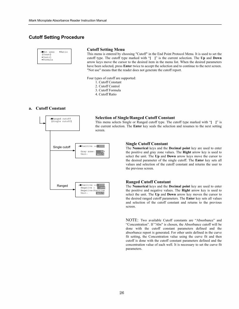
iMark Microplate Absorbance Reader Instruction Manual
27
b Cutoff Control
Selection of SingleRanged Cutoff Control This menu screen selects Single or Ranged cutoff type The cutoff type marked with ldquo[ ]rdquo is the current selection The Enter key seals the selection and resumes to the next setting screen
Single Cutoff Control The Numerical keys are used to enter the gray zone value The unit is fixed to Abs The Enter key sets the value of the cutoff control and returns to the previous screen Ranged Cutoff Control There is no parameter to set for the ranged cutoff control The Enter key returns to the previous screen NOTE CNx is the mean absorbance value of Negative control wells and CPx is the mean absorbance value of Positive control wells These wells are defined in the plate map setting The cutoff is done with the Positive and Negative value to the absorbance value of each well
c Cutoff Formula
Selection of Formula This menu screen selects a formula for cutoff calculation The formula marked with ldquo[ ]rdquo is the current selection The Up and Down arrow keys move the cursor to the desired formula type The movement of the cursor follows the scroll of this screen The Enter key marks the selection and advances the user to the next setting screen The supported formula types are
1 k CNx 2 k CPx 3 k COx 4 CNx k 5 CPx k 6 COx k 7 k + CNx 8 k + CPx 9 k + COx 10 kCNx + CPx 11 ( CNx + CPx ) k 12 k1CNx + k2CPx
Coefficient for Cutoff Formula 1 to 11 The Numerical keys and the Decimal point key are used to enter the coefficient k and gray zone values The Up and Down arrow key moves the cursor to the desired parameter of the cutoff formula The Enter key sets all values of the cutoff formula and returns to the previous screen
Positive gt= CNx Gray zone 50 Unit Abs
Positive gt= CPx Negative lt CNx Unit Abs
Enter key to accept
raquoRanged cutoff [Single cutoff]
Single cutoff
Ranged
Input coefficient k = 001 (001-10) Gray zone 50(0-99)
k CNx k CPx k COx CNx k CPx k COx k k + CNx k + CPx k + COx k CNx + CPx (CNx + CPx) k
uarr raquoCNx k bullCPx k bullCOx k darr bullk + CNx
Select formula raquo[kCNx ] bullkCPx darr bullkCOx
uarr raquok + CPx bullk + COx bullkCNx + CPx darr bull(CNx + CPx) k
uarr raquok1CNx + k2CPx
Page-1
Page-2
Page-3
Page-4
iMark Microplate Absorbance Reader Instruction Manual
28
Coefficient for Cutoff Formula 12 The Numerical keys and the Decimal point key are used to enter the coefficient k1 and k2 and gray zone values The Up and Down arrow key moves the cursor to the desired cutoff formula The Enter key sets the all values of the cutoff formula and returns to the previous screen NOTE CNx is the mean absorbance value of Negative control wells CPx is the mean absorbance value of Positive control wells and COx is the mean absorbance value of Cutoff control wells These wells are defined on the plate map setting The cutoff value is calculated using the defined formula with the defined values and coefficients
d Cutoff Ratio
Ratio to Calibrator In this screen there are three items for setting the ratio to calibrator The Up and Down arrow key moves the cursor to the desired item in the menu list The Enter key seals the selection and resumes to the next setting screen
Concentration of Calibrator The Numerical keys and the Decimal point key are used to enter the calibrator concentration value The Enter key sets the value and returns to the previous screen Unit of Calibrator Seventeen standard units are supported The unit marked with ldquo[ ]rdquo is the current selection The setting procedure is the same as the unit selection of Standards Cutoff Value Setting This menu screen selects Single or Ranged cutoff type The cutoff type marked with ldquo[ ]rdquo is the current selection The Enter key marks the selection and continues to the next setting screen Single Cutoff Control The Numerical keys are used to enter the Positive cutoff concentration value and gray zone value The Enter key sets these cutoff ratio values and returns to the previous screen Ranged Cutoff Control The Numerical keys are used to input the Positive and the Negative cutoff concentration values The Enter key sets these cutoff ratios and returns to the previous screen NOTE The calibrator concentration value is used to convert the absorbance value of each well into a concentration value The ratio of ConcentrationAbsorbance of Calibrator well is applied to the conversion The cutoff uses defined Positive and Negative values to the converted concentration value of each well
Input coefficient k1 = 001 (001-10) k2 = 100 (001-10) Gray zone 50(0-99)
k1 CNx + k2 CPx
Ratio to Calibrator raquoConcentration bullUnit bullCutoff value
Concentration 9999 unit moll
uarrraquo 01 ugdl 02 ngml 03[ pgml] darr 04 pmml
raquoPositive gt= 9999 Gray zone 50
Unit moll
raquoPositive gt= 9999 Negative lt 9999 NegativeltPositive
Unit moll
raquoRanged cutoff [Single cutoff]
Concentration
Unit
Cutoff value
Single cutoff
Ranged cutoff
iMark Microplate Absorbance Reader Instruction Manual
29
Standard Setting Procedure
Standard Curve Setting Menu This menu screen is entered by choosing STDs in the End Point Protocol Menu screen It is used to set the concentration data and the curve fit type for a standard curve or to recall a memorized standard curve The Up and Down arrow key moves the cursor to the desired item in the menu list The Enter key seals the selection and continues to the next setting screen
a STD Information Setting
STD Information In this screen there are three items for setting the concentration data of standards The Up and Down arrow keys move the cursor to the desired item in the menu list The Enter key seals the selection and continues to the next setting screen
Number of Standards The Numerical keys are used to enter the number of standards ldquo0rdquo means that the curve fit report is not used The Enter key sets the number and returns to the previous screen The maximum number of standards is 12 Concentration The Numerical keys and the Decimal point key are used to enter the concentration values of standards The Up and Down arrow keys move the cursor to the desired position The movement of the cursor also follows the scroll of this screen The Enter key sets all values of the concentration of standards and returns to the previous screen Unit Seventeen units are supported The unit marked with ldquo[ ]rdquo is the current selection The Up and Down arrow keys move the cursor to the desired unit type The movement of the cursor also follows the scroll of this screen Press Enter twice to select the unit type and to return to the previous screen The supported types of unit are
1 moll 11 pgml 2 m moll 12 Uml 3 u moll 13 IUml 4 n moll 14 uIUml 5 p moll 15 mIUml 6 mgl 16 EU 7 ngl 17 Arbit 8 pgl 9 ugdl 10 ngml
STD information raquoNumber of STD bullConcentration bullUnit
STD 1 0512 STD 2 1012 STD 3 1512 darr STD 4 2053
Standard menu raquoSTD information bullCurve fit bullRecall STD curve
Concentration
Number of STD
Number of STD = 05 (0 2ndash12)
uarrraquo 01 ugdl 02 ngml 03[ pgml] darr 04 pmml
Unit
iMark Microplate Absorbance Reader Instruction Manual
30
b Curve Fit Setting
Curve Fit In this screen there are two choices to set the curve fit The Up and Down arrow keys move the cursor to the desired item in the menu list The Enter key seals the selection and resumes to the next setting screen
Curve Fit Type 10 types of curve fit are supported as below The curve fit type marked with ldquo[ ]rdquo is the current selection The Up and Down arrow key moves the cursor to the desired curve fit type The movement of the cursor follows the scroll of this screen Press Enter twice to select the unit type and to return to the previous screen The supported curve fit types are
1 5P Logistic Rodbard 2 4P Logistic Rodbard 3 5P Logistic Cook-Wilkenson 4 4P Logistic Cook-Wilkenson 5 5P Exponential 6 Sigmoid Logistic 7 Linear regression 8 Quadratic regression 9 Cubic 10 Point To Point regression
Graph Axis Four types of graph are supported The curve fit type marked with ldquo[ ]rdquo is the current selection The Up and Down arrow keys move the cursor to the desired graph type Press Enter twice to select the unit type and to return to the previous screen The supported graph types are
1 Log - Log 2 Log - Linear 3 Linear - Log 4 Linear - Linear
uarr 5p logisticRodb raquo 4p logisticRodb [5p logisticCook] darr 4p logisticCook
raquo X-Log Y-Log [X-Log Y-Lin] X-Lin Y-Log X-Lin Y-Lin
Curve fit type
Graph axis
Curve fit setting raquoCurve fit type bullGraph axis
iMark Microplate Absorbance Reader Instruction Manual
31
c Recall STD Curve Setting
Recall Setting of Standard Curve In this screen there are two items for setting the Recall STD curve as below The Up and Down arrow keys move the cursor to the desired item in the menu list
1 Recall setting (YesNo) 2 Selecting the storage number of standard curves (1 -gt 5)
Recall Setting Move the cursor to the desired position using the Up Down or Right arrow keys Enter key accepts the setting and returns the user to the standard menu screen
Yes Recalling of the standard curve is active No Recalling of the standard curve is inactive
Storage Number Selection Five memories are selectable The vacant memory (marked with asterisks on the date and time field) is also selectable It is necessary to save a standard curve before using its protocol Move the cursor to the desired position using the Up and Down keys This setting screen consists of two parts The Right arrow key is used to switch the indication field between the date and time to the standard curve name Move the cursor to the desired position using the Up and Down keys The Enter key accepts the storage number and returns to the standard menu screen NOTE If the recall of standard curve is active (the recall setting is ldquoYesrdquo) the standard information setting and the curve fit setting will be invalidated and their setting screens will not open
Recall STD curve raquoRecall setting bullSelect STD curve
Recall setting raquoYes No
Recall setting
Select STD Curve raquo1160304 1125
2 darr 3150304 1030
Select STD Curve uarrraquo4
5
Select STD Curve raquo1 STD Curve 1
2 STD Curve 2 darr 3 STD Curve 3
Select STD Curve uarrraquo4 STD Curve 4
5 STD Curve 5
Select STD curve
Right arrow key
iMark Microplate Absorbance Reader Instruction Manual
32
Mode Setting Procedure
Mode Setting Menu This menu screen is entered by choosing the Mode in the End Point Protocol Menu screen or the Kinetic Protocol Menu screen It is used to set the plate reading conditions The Up and Down arrow keys move the cursor to the desired item in the menu list The Enter key seals the selection and resumes to the next setting screen
a Set Photo Mode
Photo Mode In this screen the user chooses Single or Dual wavelength measurement and assigns the measurement and reference (for dual wavelength measurement) filters The assignment of the reference filter appears for dual wavelength measurement The Up and Down arrow keys move the cursor to the desired parameter The Right arrow key chooses SingleDual wavelength measurement and selects the installed filter on the Filters of Edit Menu screen The Enter key seals the selection and returns to the previous screen
b Set Shaking
Shaking In this screen the user selectsdeselects shaking function sets the shaking strength and enters the shaking time A shaking time of 0s indicates no shaking The maximum shaking time is 999 seconds The Up and Down arrow key moves the cursor to the desired parameters The Right arrow key toggles between YesNo (SelectDeselect) shaking or selects strength LowMiddleHigh The Numerical keys are used to enter the shaking time The Enter key seals the selection and returns the user to the previous screen
c Set Read Mode
Read Mode In this screen the user chooses Fast or Step reading and also chooses Normal or Evaluation mode The ldquo[ ]rdquoindicates the current selection The Up and Down arrow key moves the cursor to the desired parameters The Right arrow key chooses FastStep speed or chooses NormalEval mode The Enter key seals the selection and returns to the previous screen The followings are the description of each read mode parameter Reading speed
Fast reading 6 secsingle wavelength reading 10 secdual wavelength reading
Step reading 15 secsingle wavelength reading 30 secdual wavelength reading
Reading mode
Normal mode Plate reading once Evaluation mode Four plate readings per one of measurement are performed and
the average data of their plate readings is generated as a plate data
Photometric Dual Measurement400 nm Reference 655 nm
Set Shake parameters ShakeYes SpeedMid Time 199sec(0-999)
raquoReading speed [Fast ] Step bullRead mode [Normal] Eval
raquoSet Photo mode bullSet shaking bullSet read mode
Photometric Single Measurement400 nm
iMark Microplate Absorbance Reader Instruction Manual
33
Plate Map Setting Procedure
Select Mapping Mode Menu This menu screen is entered by choosing Mapping in the End Point Protocol Menu screen or the Kinetic Protocol Menu screen It is used to map the plate format The Up and Down arrow keys move the cursor next to the desired item of menu list The Enter key seals the selection and changes this screen to the next setting screen
a Manual Mapping
Manual Mapping In this screen the user can set the plate format manually Ten well types can be set Well types The supported well types are
Well type Indication on LCD
1 Blank B 2 Sample X00hellipX99 3 Standard S01hellipS99 4 In-kit Control Positive Control CP0hellipCP9 5 Weak Positive Control CW0hellipCW9 6 Negative Control CN0hellipCN9 7 Cutoff Control CO0hellipCO9 8 Calibrator CL0hellipCL9 9 QC Control QC0hellipQC9 10 Empty well -
The key assignments of well type are ldquo0EMPrdquo Empty well ldquo5QCrdquo Quality Control well ldquo1SMPrdquo Sample well ldquo6CALrdquo Calibrator well ldquo2BLKrdquo Blank well ldquo7CPrdquo Positive Control well ldquo3STDrdquo Standard well ldquo8CNrdquo Negative Control well ldquo4COrdquo Cutoff Control well ldquo9CWrdquo Weak Positive Control well
Two Edit Modes in Plate Mapping There are two editing modes for well type input mode and for well number input The current input mode is displayed at the upper left corner of the screen When using the well type input mode the mode sign is ldquo[F]rdquo When using the well number input mode the mode sign is ldquoNrdquo The cursor that encloses the editing position of well has two types of enclosures depending on the mode For example ldquo[S01]rdquo accepts the well type keys that be assigned to the numerical keys and ldquoS01rdquo accepts the numerical input The mode is easily changed with the Decimal point key Key Functions The Up Down Right and Left arrow keys move the cursor to the desired well The movement of the cursor follows the scroll of this screen The Left arrow key will return the screen to the preceding screen or the select Mapping mode Menu only if the cursor is on column 1 At this time the selection screen appears (see the left figure) The Decimal point key changes the input mode The Numerical keys have two functions one to input the number and another to select a well type The Enter key checks the consistency between the edited plate map and other parameters memorizes the plate map into the protocol and changes this screen back to the preceding screen If it finds any inconsistency a warning message will appear on the screen
Select Mapping mode raquoManual mapping bullAutomatic mapping
N 1 2 3 4 A B CN1 S01 S01 B B CN1 S02 S02 C B CN2 S03 S03 [F] 5 6 7 8 A X11 X12 X13 X14 B X21 X22 X23 X24 C X31 X32 X33[X34]
Discard change 1Yes 2No Press 1 or 2 key
iMark Microplate Absorbance Reader Instruction Manual
34
Acceptable Number Ranges for each well type 1 Blank and Empty wells do not use numbers 2 Sample and Standard wells 00 - 99 3 Standard wells 01 - 99 4 Control and Calibrator wells 0 - 9
b Automatic Mapping
Automatic Mapping The user can input the number of each well type in this screen These defined numbers are used to set a plate map automatically Well type Nine well types are available
1 BLK Blank (0-gt10) 2 CN Control CN (0-gt9) 3 CW Control CW (0-gt9) 4 CP Control CP (0-gt9) 5 CO Control CO (0-gt9) 6 QC Control QC (0-gt9) 7 CAL Calibrator (0-gt9) 8 SMP Sample (0-gt96) 9 REP Replicate well (1-gt4)
It is possible to define the number of blanks samples calibrators and controls But the number of Standards is not included because standards are defined at the Standard Setting Menu The number of replicate wells is also included It is used for replicating each well type individually Key Functions The Up Down Right and Left arrow keys are used to move the cursor to the next position The Numerical keys are used to input the mapping parameters The Enter key accepts the mapping parameters and sets a plate map automatically using these parameters During the execution of the plate mapping the Plate auto-mapping completed message appears on the screen After that the user returns automatically to the previous Protocol Menu screen If the Left arrow key is pressed at the left end position of the cursor the left figure will appear on the screen If the user chooses Yes the system will return to the previous Protocol Menu screen If the user chooses No the system will stay in this setting screen Assigning Order and Direction of plate mapping Assigning Order The order of blanks standards samples calibrators and controls are fixed as follows Numbering for standards samples calibrators and controls is started at 1
1 Blank 2 Standard 1 -gt12 ---- NOTE 3 Control CN 1-gt9 4 Control CW 1-gt9 5 Control CP 1-gt9 6 Control CO 1-gt9 7 Control QC 1-gt9 8 Calibrator 1-gt9 9 Sample 1-gt96 10 Empty well NOTE If ldquoCutoff Controlrdquo ldquoValue by Formulardquo or ldquoRatio to Calibratorrdquo is
selected for the Cutoff plate mapping skips arranging the standards Assigning Direction The placing direction of the mapping is limited to the column direction as below
Column direction A1 -gt H1 A2 -gt H2 ----- A12 -gt H12
Discard change 1Yes 2No Press 1 or 2 key
Automatic mapping BLK= 1 CP = 1 CAL= 0 CN = 1 CO = 0 SMP=93 CW = 0 QC = 0 REP= 1
Plate auto-mapping completed
iMark Microplate Absorbance Reader Instruction Manual
35
Warning and Error of Automatic Mapping Warning screen If the total number of wells mapped exceeds 96 wells a warning message in the left figure appears on the screen The calculation of the total number of mapping wells is as follows
(Blanks+Standards+CNs+CWs+CPs+COs+QCs+Calibrators+Sample)Replicates The plate mapping is executed normally and the exceeded part is invalidated Error screen If one or more mapping parameters are over the input range an error message in the left figure will appear on the screen On the third line of the LCD the name of the parameter which is out of range and its input range will appear
Example ldquoBLK 0 ndash 10rdquo In case there is more than one error the first parameter of errors is indicated By pressing any key the user returns to the automatic mapping screen Example of automatic mapping An example of automatic mapping is as below 1 Conditions of each parameter
Blank = 1 Standard = 8 Control CN = 2 CW = 0 CP = 2 CO = 0 QC = 0 Calibrator = 1 Sample = 32 Replicate number = 2
2 Plate mapping data
1 2 3 4 5 6 7 8 9 10 11 12 A B C D E F G H
B B S1 S1 S2 S2 S3 S3
S4 S4 S5 S5 S6 S6 S7 S7
S8 S8 CN1 CN1 CN2 CN2 CP1 CP1
CP2 CP2 CL1 CL1 X1 X1 X2 X2
X3 X3 X4 X4 X5 X5 X6 X6
X7 X7 X8 X8 X9 X9 X10 X10
X11 X11 X12 X12 X13 X13 X14 X14
X15 X15 X16 X16 X17 X17 X18 X18
X19 X19 X20 X20 X21 X21 X22 X22
X23 X23 X24 X24 X25 X25 X26 X26
X27 X27 X28 X28 X29 X29 X30 X30
X31 X31 X32 X32 E E E E
Warning The total Of mapped wells has Exceeded 96 Press any key
Entered value is Out of range BLK 0 ndash 10 Press any key
iMark Microplate Absorbance Reader Instruction Manual
36
Instrument Maintenance
Caution Electrical shock hazard Always disconnect the instrument from the AC power source before opening the service compartment
Caution The lamp and the lamp cover may be very hot Use caution and allow the lamp to cool
before attempting service
Installing Interference Filters 1 With the power off open the rear cover of the instrument by pressing the
release latch located on the top left portion of the cover 2 Locate the filter wheel on the left side of the instrument Note that the
filter wheel has eight filter positions 3 Rotate the filter wheel to the desired filter Grasp the top of filter frame
and pull up to remove the filter 4 Insert the new filter into the desired filter position 5 Ensure that the new filter is added to the filter list as follows Main
menu-gtEdit-gtFilters
Changing the Lamp 1 With the power off open the rear cover of the instrument by pressing the
release latch located on the top left portion of the cover 2 Remove the two screws on the black plastic cover and carefully remove
the plastic cover 3 Remove the screw on the metal cover Lift the cover up and away from
the instrument This will allow the lamp to be pulled free from the lamp housing
4 Holding the ceramic base in one hand and the lamp housing in the other carefully pull the lamp free of the base
5 Carefully insert the new lamp firmly in the ceramic base Apply even pressure when inserting the lamp so that the bulb dose not become misaligned in the reflector housing Be extremely careful not to touch the front glass of the lamp during installation
6 Position the new lamp into the housing so that the plastic guides hold the flange of the lamp
7 Carefully place the metal cover over the lamp Tighten the screw 8 Replace the plastic cover and tighten the screws 9 Close the rear cover
iMark Microplate Absorbance Reader Instruction Manual
37
Troubleshooting and Error Messages
The iMark Microplate Reader constantly monitors several functions and displays appropriate messages on the LCD as errors are encountered
Error Recommendation
LCD appears blank on power up
a Power is not turned on The AC outlet is non-functional
b Unit is not plugged into AC outlet or power code is not attached to the instrument
Check power cord connections at outlet and on the rear panel of the instrument
1
c The AC outlet is non-functional Check circuit breakers or fuses
Instrument displays ldquoLight bulb errorrdquo message indicating that the bulb is burned out
Check whether lamp is emitting light
a Lamp is not emitting light Replace the lamp as described in x
2
b Lamp is emitting light Check the alignment of the lamp in the housing Align or replace the lamp if necessary
Printer will not print on command
3
a Printer paper is not installed properly Verify that the paper is properly installed Refer to x for details
Plate carriage jams during reading and ldquoPlate carrier errorrdquo is displayed
a Plate is not seated in carriage properly Press the STOP button immediately Position the plate carefully in the carriage making certain that it is properly seated
4
b Plate height is exceeding 16mm Use Microplate which is less than 16mm in height
5 LCD displays ldquoFilter missingrdquo Install a filter in the empty position Select the installed filter by pressing Edit key
6 LCD displays ldquoFilter disk jammedrdquo indicating that the filter wheel is not turning freely
Turn off the instrument and inspect the filter wheel Turn by hand to verify that the wheel is moving freely Make sure all the filters are properly installed and firmly seated Contact your Bio-Rad representative if the filter wheel is jammed or if the problem persists
7 LCD displays ldquoFilter not installedrdquo Enter the Edit Menu by pressing Edit key and set up the filters
iMark Microplate Absorbance Reader Instruction Manual
38
Wells have color but absorbance values seem low
a Incorrect filter used for measurement andor reference wavelength
Check wavelength used in analysis Read plate in single wavelength mode at all wavelength to verify that the proper filter was used The measurement wavelength should produce the highest absorbance
b The best measurement wavelength filter for the substrate in use has not been installed in the filter wheel
Check references for the substrate you are using or determine the best measurement wavelength by analyzing the substrate product on a scanning spectrophotometer Custom filters are available from 400 to 750 nm
8
c The filters have been switched in the wheel Check that the filters are installed in the correct position
9 ldquoPrinter errorrdquo displayed Check for paper jam Install the printer paper correctly
10 ldquoBattery errorrdquo displayed The internal battery is almost dead Contact your local Bio-Rad office
11 The following messages are displayed ldquoMemory errorrdquo ldquoCalendar errorrdquo ldquoLCD hardware errorrdquo ldquoPrinter errorrdquo ldquoLight level errorrdquo ldquoDA conversion errorrdquo ldquoAD conversion errorrdquo ldquoEEPROM errorrdquo ldquoUSB errorrdquo
Contact your local Bio-Rad office if these problems persist
iMark Microplate Absorbance Reader Instruction Manual
39
Instrument Specifications Computer interface USB 20
Plate shaking 3 speeds (low mid high) Programmable time period 0 - 999 seconds
Data storage The most recent 10 data plates for end-point most recent 2 data plates of 30 readings for kinetic readings protocol data and calendarclock function shall be kept in memory by a lithium battery even when the power is off Average lifetime of the battery shall be 5 years
Warm-up time 3 minutes
Photometric Methods Single and dual wavelength
Photo detectors 8 silicon photodiodes for measurement and 1 silicon photodiode for reference
Light source Tungsten halogen lamp 20W with 3000 hours average lifetime
Spectral range 400 nm to 750 nm
Interference filters Wavelength tolerance plusmn30 nm Band width 10 nm typically
Filter capacity 8 filters
Reading speed Fast Reading 6 sec with single wavelength reading 10 sec with dual wavelength reading
Step Reading 15 sec with single wavelength reading 25 sec with dual wavelength reading
These times are minimum interval times between repetitive reads using onboard KINETIC protocol
Indication range 0000 to 35 OD
Resolution 0001 OD
Accuracy plusmn10 or 0010 from 0 to 30 OD at 490 nm
Linearity plusmn10 from 0 to 20 OD plusmn20 from 0 to 30 OD
Reproducibility 10 or 0005 OD from 0 to 20 OD 15 from 20 to 30 OD
Inter-channel variability 15 or 0005 OD from 0 to 30 OD
Stability and Drift 0010 OD at OD=1 with single wavelength reading
Built-in Printer Thermal printer Paper width 80mm
Line Voltage Universal input 100 - 240 VAC 5060Hz
Power consumption (max) 100 VA max
Dimensions (W x D x H 346 mm x 377 mm x 164 m mm
Weight 55 kg
Operating Environment 15ordmC - 40ordmC up to 90 relative humidity without condensation
Storage Temperature 10ordmC - 50ordmC up to 90 relative humidity without condensation
Life ScienceGroup
07-0816 0108 Sig 120710013301i Rev A USEG
Bio-RadLaboratories Inc
Web site wwwbio-radcom USA 800 4BIORAD Australia 61 02 9914 2800 Austria 01 877 89 01 Belgium 09 385 55 11 Brazil 55 21 3237 9400 Canada 905 364 3435 China 86 21 6426 0808 Czech Republic 420 241 430 532 Denmark 44 52 10 00 Finland 09 804 22 00 France 01 47 95 69 65Germany 089 318 84 0 Greece 30 210 777 4396 Hong Kong 852 2789 3300 Hungary 36 1 455 8800 India 91 124 4029300 Israel 03 963 6050 Italy 39 02 216091 Japan 03 6361 7000 Korea 82 2 3473 4460 Mexico 52 555 488 7670 The Netherlands 0318 540666 New Zealand 0508 805 500 Norway 23 38 41 30 Poland 48 22 331 99 99 Portugal 351 21 472 7700 Russia 7 495 721 14 04 Singapore 65 6415 3188 South Africa 27 861 246 723 Spain 34 91 590 5200 Sweden 08 555 12700 Switzerland 061 717 95 55 Taiwan 886 2 2578 7189 United Kingdom 020 8328 2000
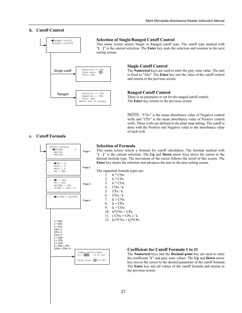
iMark Microplate Absorbance Reader Instruction Manual
28
Coefficient for Cutoff Formula 12 The Numerical keys and the Decimal point key are used to enter the coefficient k1 and k2 and gray zone values The Up and Down arrow key moves the cursor to the desired cutoff formula The Enter key sets the all values of the cutoff formula and returns to the previous screen NOTE CNx is the mean absorbance value of Negative control wells CPx is the mean absorbance value of Positive control wells and COx is the mean absorbance value of Cutoff control wells These wells are defined on the plate map setting The cutoff value is calculated using the defined formula with the defined values and coefficients
d Cutoff Ratio
Ratio to Calibrator In this screen there are three items for setting the ratio to calibrator The Up and Down arrow key moves the cursor to the desired item in the menu list The Enter key seals the selection and resumes to the next setting screen
Concentration of Calibrator The Numerical keys and the Decimal point key are used to enter the calibrator concentration value The Enter key sets the value and returns to the previous screen Unit of Calibrator Seventeen standard units are supported The unit marked with ldquo[ ]rdquo is the current selection The setting procedure is the same as the unit selection of Standards Cutoff Value Setting This menu screen selects Single or Ranged cutoff type The cutoff type marked with ldquo[ ]rdquo is the current selection The Enter key marks the selection and continues to the next setting screen Single Cutoff Control The Numerical keys are used to enter the Positive cutoff concentration value and gray zone value The Enter key sets these cutoff ratio values and returns to the previous screen Ranged Cutoff Control The Numerical keys are used to input the Positive and the Negative cutoff concentration values The Enter key sets these cutoff ratios and returns to the previous screen NOTE The calibrator concentration value is used to convert the absorbance value of each well into a concentration value The ratio of ConcentrationAbsorbance of Calibrator well is applied to the conversion The cutoff uses defined Positive and Negative values to the converted concentration value of each well
Input coefficient k1 = 001 (001-10) k2 = 100 (001-10) Gray zone 50(0-99)
k1 CNx + k2 CPx
Ratio to Calibrator raquoConcentration bullUnit bullCutoff value
Concentration 9999 unit moll
uarrraquo 01 ugdl 02 ngml 03[ pgml] darr 04 pmml
raquoPositive gt= 9999 Gray zone 50
Unit moll
raquoPositive gt= 9999 Negative lt 9999 NegativeltPositive
Unit moll
raquoRanged cutoff [Single cutoff]
Concentration
Unit
Cutoff value
Single cutoff
Ranged cutoff
iMark Microplate Absorbance Reader Instruction Manual
29
Standard Setting Procedure
Standard Curve Setting Menu This menu screen is entered by choosing STDs in the End Point Protocol Menu screen It is used to set the concentration data and the curve fit type for a standard curve or to recall a memorized standard curve The Up and Down arrow key moves the cursor to the desired item in the menu list The Enter key seals the selection and continues to the next setting screen
a STD Information Setting
STD Information In this screen there are three items for setting the concentration data of standards The Up and Down arrow keys move the cursor to the desired item in the menu list The Enter key seals the selection and continues to the next setting screen
Number of Standards The Numerical keys are used to enter the number of standards ldquo0rdquo means that the curve fit report is not used The Enter key sets the number and returns to the previous screen The maximum number of standards is 12 Concentration The Numerical keys and the Decimal point key are used to enter the concentration values of standards The Up and Down arrow keys move the cursor to the desired position The movement of the cursor also follows the scroll of this screen The Enter key sets all values of the concentration of standards and returns to the previous screen Unit Seventeen units are supported The unit marked with ldquo[ ]rdquo is the current selection The Up and Down arrow keys move the cursor to the desired unit type The movement of the cursor also follows the scroll of this screen Press Enter twice to select the unit type and to return to the previous screen The supported types of unit are
1 moll 11 pgml 2 m moll 12 Uml 3 u moll 13 IUml 4 n moll 14 uIUml 5 p moll 15 mIUml 6 mgl 16 EU 7 ngl 17 Arbit 8 pgl 9 ugdl 10 ngml
STD information raquoNumber of STD bullConcentration bullUnit
STD 1 0512 STD 2 1012 STD 3 1512 darr STD 4 2053
Standard menu raquoSTD information bullCurve fit bullRecall STD curve
Concentration
Number of STD
Number of STD = 05 (0 2ndash12)
uarrraquo 01 ugdl 02 ngml 03[ pgml] darr 04 pmml
Unit
iMark Microplate Absorbance Reader Instruction Manual
30
b Curve Fit Setting
Curve Fit In this screen there are two choices to set the curve fit The Up and Down arrow keys move the cursor to the desired item in the menu list The Enter key seals the selection and resumes to the next setting screen
Curve Fit Type 10 types of curve fit are supported as below The curve fit type marked with ldquo[ ]rdquo is the current selection The Up and Down arrow key moves the cursor to the desired curve fit type The movement of the cursor follows the scroll of this screen Press Enter twice to select the unit type and to return to the previous screen The supported curve fit types are
1 5P Logistic Rodbard 2 4P Logistic Rodbard 3 5P Logistic Cook-Wilkenson 4 4P Logistic Cook-Wilkenson 5 5P Exponential 6 Sigmoid Logistic 7 Linear regression 8 Quadratic regression 9 Cubic 10 Point To Point regression
Graph Axis Four types of graph are supported The curve fit type marked with ldquo[ ]rdquo is the current selection The Up and Down arrow keys move the cursor to the desired graph type Press Enter twice to select the unit type and to return to the previous screen The supported graph types are
1 Log - Log 2 Log - Linear 3 Linear - Log 4 Linear - Linear
uarr 5p logisticRodb raquo 4p logisticRodb [5p logisticCook] darr 4p logisticCook
raquo X-Log Y-Log [X-Log Y-Lin] X-Lin Y-Log X-Lin Y-Lin
Curve fit type
Graph axis
Curve fit setting raquoCurve fit type bullGraph axis
iMark Microplate Absorbance Reader Instruction Manual
31
c Recall STD Curve Setting
Recall Setting of Standard Curve In this screen there are two items for setting the Recall STD curve as below The Up and Down arrow keys move the cursor to the desired item in the menu list
1 Recall setting (YesNo) 2 Selecting the storage number of standard curves (1 -gt 5)
Recall Setting Move the cursor to the desired position using the Up Down or Right arrow keys Enter key accepts the setting and returns the user to the standard menu screen
Yes Recalling of the standard curve is active No Recalling of the standard curve is inactive
Storage Number Selection Five memories are selectable The vacant memory (marked with asterisks on the date and time field) is also selectable It is necessary to save a standard curve before using its protocol Move the cursor to the desired position using the Up and Down keys This setting screen consists of two parts The Right arrow key is used to switch the indication field between the date and time to the standard curve name Move the cursor to the desired position using the Up and Down keys The Enter key accepts the storage number and returns to the standard menu screen NOTE If the recall of standard curve is active (the recall setting is ldquoYesrdquo) the standard information setting and the curve fit setting will be invalidated and their setting screens will not open
Recall STD curve raquoRecall setting bullSelect STD curve
Recall setting raquoYes No
Recall setting
Select STD Curve raquo1160304 1125
2 darr 3150304 1030
Select STD Curve uarrraquo4
5
Select STD Curve raquo1 STD Curve 1
2 STD Curve 2 darr 3 STD Curve 3
Select STD Curve uarrraquo4 STD Curve 4
5 STD Curve 5
Select STD curve
Right arrow key
iMark Microplate Absorbance Reader Instruction Manual
32
Mode Setting Procedure
Mode Setting Menu This menu screen is entered by choosing the Mode in the End Point Protocol Menu screen or the Kinetic Protocol Menu screen It is used to set the plate reading conditions The Up and Down arrow keys move the cursor to the desired item in the menu list The Enter key seals the selection and resumes to the next setting screen
a Set Photo Mode
Photo Mode In this screen the user chooses Single or Dual wavelength measurement and assigns the measurement and reference (for dual wavelength measurement) filters The assignment of the reference filter appears for dual wavelength measurement The Up and Down arrow keys move the cursor to the desired parameter The Right arrow key chooses SingleDual wavelength measurement and selects the installed filter on the Filters of Edit Menu screen The Enter key seals the selection and returns to the previous screen
b Set Shaking
Shaking In this screen the user selectsdeselects shaking function sets the shaking strength and enters the shaking time A shaking time of 0s indicates no shaking The maximum shaking time is 999 seconds The Up and Down arrow key moves the cursor to the desired parameters The Right arrow key toggles between YesNo (SelectDeselect) shaking or selects strength LowMiddleHigh The Numerical keys are used to enter the shaking time The Enter key seals the selection and returns the user to the previous screen
c Set Read Mode
Read Mode In this screen the user chooses Fast or Step reading and also chooses Normal or Evaluation mode The ldquo[ ]rdquoindicates the current selection The Up and Down arrow key moves the cursor to the desired parameters The Right arrow key chooses FastStep speed or chooses NormalEval mode The Enter key seals the selection and returns to the previous screen The followings are the description of each read mode parameter Reading speed
Fast reading 6 secsingle wavelength reading 10 secdual wavelength reading
Step reading 15 secsingle wavelength reading 30 secdual wavelength reading
Reading mode
Normal mode Plate reading once Evaluation mode Four plate readings per one of measurement are performed and
the average data of their plate readings is generated as a plate data
Photometric Dual Measurement400 nm Reference 655 nm
Set Shake parameters ShakeYes SpeedMid Time 199sec(0-999)
raquoReading speed [Fast ] Step bullRead mode [Normal] Eval
raquoSet Photo mode bullSet shaking bullSet read mode
Photometric Single Measurement400 nm
iMark Microplate Absorbance Reader Instruction Manual
33
Plate Map Setting Procedure
Select Mapping Mode Menu This menu screen is entered by choosing Mapping in the End Point Protocol Menu screen or the Kinetic Protocol Menu screen It is used to map the plate format The Up and Down arrow keys move the cursor next to the desired item of menu list The Enter key seals the selection and changes this screen to the next setting screen
a Manual Mapping
Manual Mapping In this screen the user can set the plate format manually Ten well types can be set Well types The supported well types are
Well type Indication on LCD
1 Blank B 2 Sample X00hellipX99 3 Standard S01hellipS99 4 In-kit Control Positive Control CP0hellipCP9 5 Weak Positive Control CW0hellipCW9 6 Negative Control CN0hellipCN9 7 Cutoff Control CO0hellipCO9 8 Calibrator CL0hellipCL9 9 QC Control QC0hellipQC9 10 Empty well -
The key assignments of well type are ldquo0EMPrdquo Empty well ldquo5QCrdquo Quality Control well ldquo1SMPrdquo Sample well ldquo6CALrdquo Calibrator well ldquo2BLKrdquo Blank well ldquo7CPrdquo Positive Control well ldquo3STDrdquo Standard well ldquo8CNrdquo Negative Control well ldquo4COrdquo Cutoff Control well ldquo9CWrdquo Weak Positive Control well
Two Edit Modes in Plate Mapping There are two editing modes for well type input mode and for well number input The current input mode is displayed at the upper left corner of the screen When using the well type input mode the mode sign is ldquo[F]rdquo When using the well number input mode the mode sign is ldquoNrdquo The cursor that encloses the editing position of well has two types of enclosures depending on the mode For example ldquo[S01]rdquo accepts the well type keys that be assigned to the numerical keys and ldquoS01rdquo accepts the numerical input The mode is easily changed with the Decimal point key Key Functions The Up Down Right and Left arrow keys move the cursor to the desired well The movement of the cursor follows the scroll of this screen The Left arrow key will return the screen to the preceding screen or the select Mapping mode Menu only if the cursor is on column 1 At this time the selection screen appears (see the left figure) The Decimal point key changes the input mode The Numerical keys have two functions one to input the number and another to select a well type The Enter key checks the consistency between the edited plate map and other parameters memorizes the plate map into the protocol and changes this screen back to the preceding screen If it finds any inconsistency a warning message will appear on the screen
Select Mapping mode raquoManual mapping bullAutomatic mapping
N 1 2 3 4 A B CN1 S01 S01 B B CN1 S02 S02 C B CN2 S03 S03 [F] 5 6 7 8 A X11 X12 X13 X14 B X21 X22 X23 X24 C X31 X32 X33[X34]
Discard change 1Yes 2No Press 1 or 2 key
iMark Microplate Absorbance Reader Instruction Manual
34
Acceptable Number Ranges for each well type 1 Blank and Empty wells do not use numbers 2 Sample and Standard wells 00 - 99 3 Standard wells 01 - 99 4 Control and Calibrator wells 0 - 9
b Automatic Mapping
Automatic Mapping The user can input the number of each well type in this screen These defined numbers are used to set a plate map automatically Well type Nine well types are available
1 BLK Blank (0-gt10) 2 CN Control CN (0-gt9) 3 CW Control CW (0-gt9) 4 CP Control CP (0-gt9) 5 CO Control CO (0-gt9) 6 QC Control QC (0-gt9) 7 CAL Calibrator (0-gt9) 8 SMP Sample (0-gt96) 9 REP Replicate well (1-gt4)
It is possible to define the number of blanks samples calibrators and controls But the number of Standards is not included because standards are defined at the Standard Setting Menu The number of replicate wells is also included It is used for replicating each well type individually Key Functions The Up Down Right and Left arrow keys are used to move the cursor to the next position The Numerical keys are used to input the mapping parameters The Enter key accepts the mapping parameters and sets a plate map automatically using these parameters During the execution of the plate mapping the Plate auto-mapping completed message appears on the screen After that the user returns automatically to the previous Protocol Menu screen If the Left arrow key is pressed at the left end position of the cursor the left figure will appear on the screen If the user chooses Yes the system will return to the previous Protocol Menu screen If the user chooses No the system will stay in this setting screen Assigning Order and Direction of plate mapping Assigning Order The order of blanks standards samples calibrators and controls are fixed as follows Numbering for standards samples calibrators and controls is started at 1
1 Blank 2 Standard 1 -gt12 ---- NOTE 3 Control CN 1-gt9 4 Control CW 1-gt9 5 Control CP 1-gt9 6 Control CO 1-gt9 7 Control QC 1-gt9 8 Calibrator 1-gt9 9 Sample 1-gt96 10 Empty well NOTE If ldquoCutoff Controlrdquo ldquoValue by Formulardquo or ldquoRatio to Calibratorrdquo is
selected for the Cutoff plate mapping skips arranging the standards Assigning Direction The placing direction of the mapping is limited to the column direction as below
Column direction A1 -gt H1 A2 -gt H2 ----- A12 -gt H12
Discard change 1Yes 2No Press 1 or 2 key
Automatic mapping BLK= 1 CP = 1 CAL= 0 CN = 1 CO = 0 SMP=93 CW = 0 QC = 0 REP= 1
Plate auto-mapping completed
iMark Microplate Absorbance Reader Instruction Manual
35
Warning and Error of Automatic Mapping Warning screen If the total number of wells mapped exceeds 96 wells a warning message in the left figure appears on the screen The calculation of the total number of mapping wells is as follows
(Blanks+Standards+CNs+CWs+CPs+COs+QCs+Calibrators+Sample)Replicates The plate mapping is executed normally and the exceeded part is invalidated Error screen If one or more mapping parameters are over the input range an error message in the left figure will appear on the screen On the third line of the LCD the name of the parameter which is out of range and its input range will appear
Example ldquoBLK 0 ndash 10rdquo In case there is more than one error the first parameter of errors is indicated By pressing any key the user returns to the automatic mapping screen Example of automatic mapping An example of automatic mapping is as below 1 Conditions of each parameter
Blank = 1 Standard = 8 Control CN = 2 CW = 0 CP = 2 CO = 0 QC = 0 Calibrator = 1 Sample = 32 Replicate number = 2
2 Plate mapping data
1 2 3 4 5 6 7 8 9 10 11 12 A B C D E F G H
B B S1 S1 S2 S2 S3 S3
S4 S4 S5 S5 S6 S6 S7 S7
S8 S8 CN1 CN1 CN2 CN2 CP1 CP1
CP2 CP2 CL1 CL1 X1 X1 X2 X2
X3 X3 X4 X4 X5 X5 X6 X6
X7 X7 X8 X8 X9 X9 X10 X10
X11 X11 X12 X12 X13 X13 X14 X14
X15 X15 X16 X16 X17 X17 X18 X18
X19 X19 X20 X20 X21 X21 X22 X22
X23 X23 X24 X24 X25 X25 X26 X26
X27 X27 X28 X28 X29 X29 X30 X30
X31 X31 X32 X32 E E E E
Warning The total Of mapped wells has Exceeded 96 Press any key
Entered value is Out of range BLK 0 ndash 10 Press any key
iMark Microplate Absorbance Reader Instruction Manual
36
Instrument Maintenance
Caution Electrical shock hazard Always disconnect the instrument from the AC power source before opening the service compartment
Caution The lamp and the lamp cover may be very hot Use caution and allow the lamp to cool
before attempting service
Installing Interference Filters 1 With the power off open the rear cover of the instrument by pressing the
release latch located on the top left portion of the cover 2 Locate the filter wheel on the left side of the instrument Note that the
filter wheel has eight filter positions 3 Rotate the filter wheel to the desired filter Grasp the top of filter frame
and pull up to remove the filter 4 Insert the new filter into the desired filter position 5 Ensure that the new filter is added to the filter list as follows Main
menu-gtEdit-gtFilters
Changing the Lamp 1 With the power off open the rear cover of the instrument by pressing the
release latch located on the top left portion of the cover 2 Remove the two screws on the black plastic cover and carefully remove
the plastic cover 3 Remove the screw on the metal cover Lift the cover up and away from
the instrument This will allow the lamp to be pulled free from the lamp housing
4 Holding the ceramic base in one hand and the lamp housing in the other carefully pull the lamp free of the base
5 Carefully insert the new lamp firmly in the ceramic base Apply even pressure when inserting the lamp so that the bulb dose not become misaligned in the reflector housing Be extremely careful not to touch the front glass of the lamp during installation
6 Position the new lamp into the housing so that the plastic guides hold the flange of the lamp
7 Carefully place the metal cover over the lamp Tighten the screw 8 Replace the plastic cover and tighten the screws 9 Close the rear cover
iMark Microplate Absorbance Reader Instruction Manual
37
Troubleshooting and Error Messages
The iMark Microplate Reader constantly monitors several functions and displays appropriate messages on the LCD as errors are encountered
Error Recommendation
LCD appears blank on power up
a Power is not turned on The AC outlet is non-functional
b Unit is not plugged into AC outlet or power code is not attached to the instrument
Check power cord connections at outlet and on the rear panel of the instrument
1
c The AC outlet is non-functional Check circuit breakers or fuses
Instrument displays ldquoLight bulb errorrdquo message indicating that the bulb is burned out
Check whether lamp is emitting light
a Lamp is not emitting light Replace the lamp as described in x
2
b Lamp is emitting light Check the alignment of the lamp in the housing Align or replace the lamp if necessary
Printer will not print on command
3
a Printer paper is not installed properly Verify that the paper is properly installed Refer to x for details
Plate carriage jams during reading and ldquoPlate carrier errorrdquo is displayed
a Plate is not seated in carriage properly Press the STOP button immediately Position the plate carefully in the carriage making certain that it is properly seated
4
b Plate height is exceeding 16mm Use Microplate which is less than 16mm in height
5 LCD displays ldquoFilter missingrdquo Install a filter in the empty position Select the installed filter by pressing Edit key
6 LCD displays ldquoFilter disk jammedrdquo indicating that the filter wheel is not turning freely
Turn off the instrument and inspect the filter wheel Turn by hand to verify that the wheel is moving freely Make sure all the filters are properly installed and firmly seated Contact your Bio-Rad representative if the filter wheel is jammed or if the problem persists
7 LCD displays ldquoFilter not installedrdquo Enter the Edit Menu by pressing Edit key and set up the filters
iMark Microplate Absorbance Reader Instruction Manual
38
Wells have color but absorbance values seem low
a Incorrect filter used for measurement andor reference wavelength
Check wavelength used in analysis Read plate in single wavelength mode at all wavelength to verify that the proper filter was used The measurement wavelength should produce the highest absorbance
b The best measurement wavelength filter for the substrate in use has not been installed in the filter wheel
Check references for the substrate you are using or determine the best measurement wavelength by analyzing the substrate product on a scanning spectrophotometer Custom filters are available from 400 to 750 nm
8
c The filters have been switched in the wheel Check that the filters are installed in the correct position
9 ldquoPrinter errorrdquo displayed Check for paper jam Install the printer paper correctly
10 ldquoBattery errorrdquo displayed The internal battery is almost dead Contact your local Bio-Rad office
11 The following messages are displayed ldquoMemory errorrdquo ldquoCalendar errorrdquo ldquoLCD hardware errorrdquo ldquoPrinter errorrdquo ldquoLight level errorrdquo ldquoDA conversion errorrdquo ldquoAD conversion errorrdquo ldquoEEPROM errorrdquo ldquoUSB errorrdquo
Contact your local Bio-Rad office if these problems persist
iMark Microplate Absorbance Reader Instruction Manual
39
Instrument Specifications Computer interface USB 20
Plate shaking 3 speeds (low mid high) Programmable time period 0 - 999 seconds
Data storage The most recent 10 data plates for end-point most recent 2 data plates of 30 readings for kinetic readings protocol data and calendarclock function shall be kept in memory by a lithium battery even when the power is off Average lifetime of the battery shall be 5 years
Warm-up time 3 minutes
Photometric Methods Single and dual wavelength
Photo detectors 8 silicon photodiodes for measurement and 1 silicon photodiode for reference
Light source Tungsten halogen lamp 20W with 3000 hours average lifetime
Spectral range 400 nm to 750 nm
Interference filters Wavelength tolerance plusmn30 nm Band width 10 nm typically
Filter capacity 8 filters
Reading speed Fast Reading 6 sec with single wavelength reading 10 sec with dual wavelength reading
Step Reading 15 sec with single wavelength reading 25 sec with dual wavelength reading
These times are minimum interval times between repetitive reads using onboard KINETIC protocol
Indication range 0000 to 35 OD
Resolution 0001 OD
Accuracy plusmn10 or 0010 from 0 to 30 OD at 490 nm
Linearity plusmn10 from 0 to 20 OD plusmn20 from 0 to 30 OD
Reproducibility 10 or 0005 OD from 0 to 20 OD 15 from 20 to 30 OD
Inter-channel variability 15 or 0005 OD from 0 to 30 OD
Stability and Drift 0010 OD at OD=1 with single wavelength reading
Built-in Printer Thermal printer Paper width 80mm
Line Voltage Universal input 100 - 240 VAC 5060Hz
Power consumption (max) 100 VA max
Dimensions (W x D x H 346 mm x 377 mm x 164 m mm
Weight 55 kg
Operating Environment 15ordmC - 40ordmC up to 90 relative humidity without condensation
Storage Temperature 10ordmC - 50ordmC up to 90 relative humidity without condensation
Life ScienceGroup
07-0816 0108 Sig 120710013301i Rev A USEG
Bio-RadLaboratories Inc
Web site wwwbio-radcom USA 800 4BIORAD Australia 61 02 9914 2800 Austria 01 877 89 01 Belgium 09 385 55 11 Brazil 55 21 3237 9400 Canada 905 364 3435 China 86 21 6426 0808 Czech Republic 420 241 430 532 Denmark 44 52 10 00 Finland 09 804 22 00 France 01 47 95 69 65Germany 089 318 84 0 Greece 30 210 777 4396 Hong Kong 852 2789 3300 Hungary 36 1 455 8800 India 91 124 4029300 Israel 03 963 6050 Italy 39 02 216091 Japan 03 6361 7000 Korea 82 2 3473 4460 Mexico 52 555 488 7670 The Netherlands 0318 540666 New Zealand 0508 805 500 Norway 23 38 41 30 Poland 48 22 331 99 99 Portugal 351 21 472 7700 Russia 7 495 721 14 04 Singapore 65 6415 3188 South Africa 27 861 246 723 Spain 34 91 590 5200 Sweden 08 555 12700 Switzerland 061 717 95 55 Taiwan 886 2 2578 7189 United Kingdom 020 8328 2000
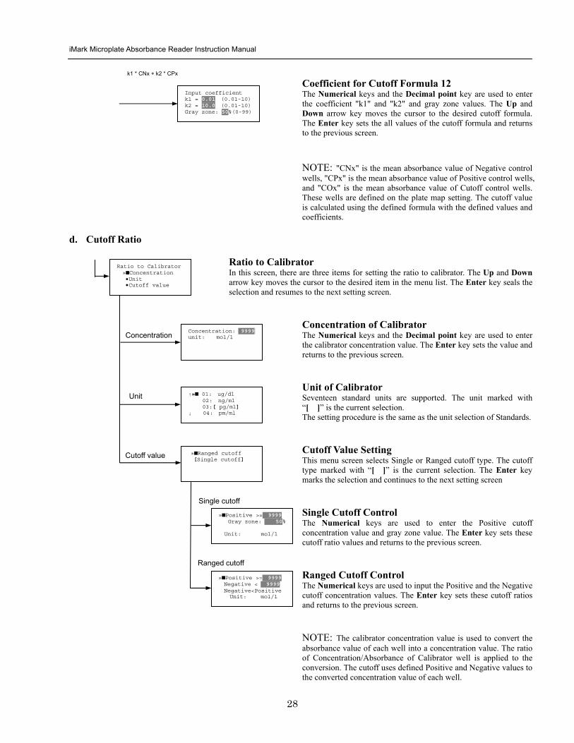
iMark Microplate Absorbance Reader Instruction Manual
29
Standard Setting Procedure
Standard Curve Setting Menu This menu screen is entered by choosing STDs in the End Point Protocol Menu screen It is used to set the concentration data and the curve fit type for a standard curve or to recall a memorized standard curve The Up and Down arrow key moves the cursor to the desired item in the menu list The Enter key seals the selection and continues to the next setting screen
a STD Information Setting
STD Information In this screen there are three items for setting the concentration data of standards The Up and Down arrow keys move the cursor to the desired item in the menu list The Enter key seals the selection and continues to the next setting screen
Number of Standards The Numerical keys are used to enter the number of standards ldquo0rdquo means that the curve fit report is not used The Enter key sets the number and returns to the previous screen The maximum number of standards is 12 Concentration The Numerical keys and the Decimal point key are used to enter the concentration values of standards The Up and Down arrow keys move the cursor to the desired position The movement of the cursor also follows the scroll of this screen The Enter key sets all values of the concentration of standards and returns to the previous screen Unit Seventeen units are supported The unit marked with ldquo[ ]rdquo is the current selection The Up and Down arrow keys move the cursor to the desired unit type The movement of the cursor also follows the scroll of this screen Press Enter twice to select the unit type and to return to the previous screen The supported types of unit are
1 moll 11 pgml 2 m moll 12 Uml 3 u moll 13 IUml 4 n moll 14 uIUml 5 p moll 15 mIUml 6 mgl 16 EU 7 ngl 17 Arbit 8 pgl 9 ugdl 10 ngml
STD information raquoNumber of STD bullConcentration bullUnit
STD 1 0512 STD 2 1012 STD 3 1512 darr STD 4 2053
Standard menu raquoSTD information bullCurve fit bullRecall STD curve
Concentration
Number of STD
Number of STD = 05 (0 2ndash12)
uarrraquo 01 ugdl 02 ngml 03[ pgml] darr 04 pmml
Unit
iMark Microplate Absorbance Reader Instruction Manual
30
b Curve Fit Setting
Curve Fit In this screen there are two choices to set the curve fit The Up and Down arrow keys move the cursor to the desired item in the menu list The Enter key seals the selection and resumes to the next setting screen
Curve Fit Type 10 types of curve fit are supported as below The curve fit type marked with ldquo[ ]rdquo is the current selection The Up and Down arrow key moves the cursor to the desired curve fit type The movement of the cursor follows the scroll of this screen Press Enter twice to select the unit type and to return to the previous screen The supported curve fit types are
1 5P Logistic Rodbard 2 4P Logistic Rodbard 3 5P Logistic Cook-Wilkenson 4 4P Logistic Cook-Wilkenson 5 5P Exponential 6 Sigmoid Logistic 7 Linear regression 8 Quadratic regression 9 Cubic 10 Point To Point regression
Graph Axis Four types of graph are supported The curve fit type marked with ldquo[ ]rdquo is the current selection The Up and Down arrow keys move the cursor to the desired graph type Press Enter twice to select the unit type and to return to the previous screen The supported graph types are
1 Log - Log 2 Log - Linear 3 Linear - Log 4 Linear - Linear
uarr 5p logisticRodb raquo 4p logisticRodb [5p logisticCook] darr 4p logisticCook
raquo X-Log Y-Log [X-Log Y-Lin] X-Lin Y-Log X-Lin Y-Lin
Curve fit type
Graph axis
Curve fit setting raquoCurve fit type bullGraph axis
iMark Microplate Absorbance Reader Instruction Manual
31
c Recall STD Curve Setting
Recall Setting of Standard Curve In this screen there are two items for setting the Recall STD curve as below The Up and Down arrow keys move the cursor to the desired item in the menu list
1 Recall setting (YesNo) 2 Selecting the storage number of standard curves (1 -gt 5)
Recall Setting Move the cursor to the desired position using the Up Down or Right arrow keys Enter key accepts the setting and returns the user to the standard menu screen
Yes Recalling of the standard curve is active No Recalling of the standard curve is inactive
Storage Number Selection Five memories are selectable The vacant memory (marked with asterisks on the date and time field) is also selectable It is necessary to save a standard curve before using its protocol Move the cursor to the desired position using the Up and Down keys This setting screen consists of two parts The Right arrow key is used to switch the indication field between the date and time to the standard curve name Move the cursor to the desired position using the Up and Down keys The Enter key accepts the storage number and returns to the standard menu screen NOTE If the recall of standard curve is active (the recall setting is ldquoYesrdquo) the standard information setting and the curve fit setting will be invalidated and their setting screens will not open
Recall STD curve raquoRecall setting bullSelect STD curve
Recall setting raquoYes No
Recall setting
Select STD Curve raquo1160304 1125
2 darr 3150304 1030
Select STD Curve uarrraquo4
5
Select STD Curve raquo1 STD Curve 1
2 STD Curve 2 darr 3 STD Curve 3
Select STD Curve uarrraquo4 STD Curve 4
5 STD Curve 5
Select STD curve
Right arrow key
iMark Microplate Absorbance Reader Instruction Manual
32
Mode Setting Procedure
Mode Setting Menu This menu screen is entered by choosing the Mode in the End Point Protocol Menu screen or the Kinetic Protocol Menu screen It is used to set the plate reading conditions The Up and Down arrow keys move the cursor to the desired item in the menu list The Enter key seals the selection and resumes to the next setting screen
a Set Photo Mode
Photo Mode In this screen the user chooses Single or Dual wavelength measurement and assigns the measurement and reference (for dual wavelength measurement) filters The assignment of the reference filter appears for dual wavelength measurement The Up and Down arrow keys move the cursor to the desired parameter The Right arrow key chooses SingleDual wavelength measurement and selects the installed filter on the Filters of Edit Menu screen The Enter key seals the selection and returns to the previous screen
b Set Shaking
Shaking In this screen the user selectsdeselects shaking function sets the shaking strength and enters the shaking time A shaking time of 0s indicates no shaking The maximum shaking time is 999 seconds The Up and Down arrow key moves the cursor to the desired parameters The Right arrow key toggles between YesNo (SelectDeselect) shaking or selects strength LowMiddleHigh The Numerical keys are used to enter the shaking time The Enter key seals the selection and returns the user to the previous screen
c Set Read Mode
Read Mode In this screen the user chooses Fast or Step reading and also chooses Normal or Evaluation mode The ldquo[ ]rdquoindicates the current selection The Up and Down arrow key moves the cursor to the desired parameters The Right arrow key chooses FastStep speed or chooses NormalEval mode The Enter key seals the selection and returns to the previous screen The followings are the description of each read mode parameter Reading speed
Fast reading 6 secsingle wavelength reading 10 secdual wavelength reading
Step reading 15 secsingle wavelength reading 30 secdual wavelength reading
Reading mode
Normal mode Plate reading once Evaluation mode Four plate readings per one of measurement are performed and
the average data of their plate readings is generated as a plate data
Photometric Dual Measurement400 nm Reference 655 nm
Set Shake parameters ShakeYes SpeedMid Time 199sec(0-999)
raquoReading speed [Fast ] Step bullRead mode [Normal] Eval
raquoSet Photo mode bullSet shaking bullSet read mode
Photometric Single Measurement400 nm
iMark Microplate Absorbance Reader Instruction Manual
33
Plate Map Setting Procedure
Select Mapping Mode Menu This menu screen is entered by choosing Mapping in the End Point Protocol Menu screen or the Kinetic Protocol Menu screen It is used to map the plate format The Up and Down arrow keys move the cursor next to the desired item of menu list The Enter key seals the selection and changes this screen to the next setting screen
a Manual Mapping
Manual Mapping In this screen the user can set the plate format manually Ten well types can be set Well types The supported well types are
Well type Indication on LCD
1 Blank B 2 Sample X00hellipX99 3 Standard S01hellipS99 4 In-kit Control Positive Control CP0hellipCP9 5 Weak Positive Control CW0hellipCW9 6 Negative Control CN0hellipCN9 7 Cutoff Control CO0hellipCO9 8 Calibrator CL0hellipCL9 9 QC Control QC0hellipQC9 10 Empty well -
The key assignments of well type are ldquo0EMPrdquo Empty well ldquo5QCrdquo Quality Control well ldquo1SMPrdquo Sample well ldquo6CALrdquo Calibrator well ldquo2BLKrdquo Blank well ldquo7CPrdquo Positive Control well ldquo3STDrdquo Standard well ldquo8CNrdquo Negative Control well ldquo4COrdquo Cutoff Control well ldquo9CWrdquo Weak Positive Control well
Two Edit Modes in Plate Mapping There are two editing modes for well type input mode and for well number input The current input mode is displayed at the upper left corner of the screen When using the well type input mode the mode sign is ldquo[F]rdquo When using the well number input mode the mode sign is ldquoNrdquo The cursor that encloses the editing position of well has two types of enclosures depending on the mode For example ldquo[S01]rdquo accepts the well type keys that be assigned to the numerical keys and ldquoS01rdquo accepts the numerical input The mode is easily changed with the Decimal point key Key Functions The Up Down Right and Left arrow keys move the cursor to the desired well The movement of the cursor follows the scroll of this screen The Left arrow key will return the screen to the preceding screen or the select Mapping mode Menu only if the cursor is on column 1 At this time the selection screen appears (see the left figure) The Decimal point key changes the input mode The Numerical keys have two functions one to input the number and another to select a well type The Enter key checks the consistency between the edited plate map and other parameters memorizes the plate map into the protocol and changes this screen back to the preceding screen If it finds any inconsistency a warning message will appear on the screen
Select Mapping mode raquoManual mapping bullAutomatic mapping
N 1 2 3 4 A B CN1 S01 S01 B B CN1 S02 S02 C B CN2 S03 S03 [F] 5 6 7 8 A X11 X12 X13 X14 B X21 X22 X23 X24 C X31 X32 X33[X34]
Discard change 1Yes 2No Press 1 or 2 key
iMark Microplate Absorbance Reader Instruction Manual
34
Acceptable Number Ranges for each well type 1 Blank and Empty wells do not use numbers 2 Sample and Standard wells 00 - 99 3 Standard wells 01 - 99 4 Control and Calibrator wells 0 - 9
b Automatic Mapping
Automatic Mapping The user can input the number of each well type in this screen These defined numbers are used to set a plate map automatically Well type Nine well types are available
1 BLK Blank (0-gt10) 2 CN Control CN (0-gt9) 3 CW Control CW (0-gt9) 4 CP Control CP (0-gt9) 5 CO Control CO (0-gt9) 6 QC Control QC (0-gt9) 7 CAL Calibrator (0-gt9) 8 SMP Sample (0-gt96) 9 REP Replicate well (1-gt4)
It is possible to define the number of blanks samples calibrators and controls But the number of Standards is not included because standards are defined at the Standard Setting Menu The number of replicate wells is also included It is used for replicating each well type individually Key Functions The Up Down Right and Left arrow keys are used to move the cursor to the next position The Numerical keys are used to input the mapping parameters The Enter key accepts the mapping parameters and sets a plate map automatically using these parameters During the execution of the plate mapping the Plate auto-mapping completed message appears on the screen After that the user returns automatically to the previous Protocol Menu screen If the Left arrow key is pressed at the left end position of the cursor the left figure will appear on the screen If the user chooses Yes the system will return to the previous Protocol Menu screen If the user chooses No the system will stay in this setting screen Assigning Order and Direction of plate mapping Assigning Order The order of blanks standards samples calibrators and controls are fixed as follows Numbering for standards samples calibrators and controls is started at 1
1 Blank 2 Standard 1 -gt12 ---- NOTE 3 Control CN 1-gt9 4 Control CW 1-gt9 5 Control CP 1-gt9 6 Control CO 1-gt9 7 Control QC 1-gt9 8 Calibrator 1-gt9 9 Sample 1-gt96 10 Empty well NOTE If ldquoCutoff Controlrdquo ldquoValue by Formulardquo or ldquoRatio to Calibratorrdquo is
selected for the Cutoff plate mapping skips arranging the standards Assigning Direction The placing direction of the mapping is limited to the column direction as below
Column direction A1 -gt H1 A2 -gt H2 ----- A12 -gt H12
Discard change 1Yes 2No Press 1 or 2 key
Automatic mapping BLK= 1 CP = 1 CAL= 0 CN = 1 CO = 0 SMP=93 CW = 0 QC = 0 REP= 1
Plate auto-mapping completed
iMark Microplate Absorbance Reader Instruction Manual
35
Warning and Error of Automatic Mapping Warning screen If the total number of wells mapped exceeds 96 wells a warning message in the left figure appears on the screen The calculation of the total number of mapping wells is as follows
(Blanks+Standards+CNs+CWs+CPs+COs+QCs+Calibrators+Sample)Replicates The plate mapping is executed normally and the exceeded part is invalidated Error screen If one or more mapping parameters are over the input range an error message in the left figure will appear on the screen On the third line of the LCD the name of the parameter which is out of range and its input range will appear
Example ldquoBLK 0 ndash 10rdquo In case there is more than one error the first parameter of errors is indicated By pressing any key the user returns to the automatic mapping screen Example of automatic mapping An example of automatic mapping is as below 1 Conditions of each parameter
Blank = 1 Standard = 8 Control CN = 2 CW = 0 CP = 2 CO = 0 QC = 0 Calibrator = 1 Sample = 32 Replicate number = 2
2 Plate mapping data
1 2 3 4 5 6 7 8 9 10 11 12 A B C D E F G H
B B S1 S1 S2 S2 S3 S3
S4 S4 S5 S5 S6 S6 S7 S7
S8 S8 CN1 CN1 CN2 CN2 CP1 CP1
CP2 CP2 CL1 CL1 X1 X1 X2 X2
X3 X3 X4 X4 X5 X5 X6 X6
X7 X7 X8 X8 X9 X9 X10 X10
X11 X11 X12 X12 X13 X13 X14 X14
X15 X15 X16 X16 X17 X17 X18 X18
X19 X19 X20 X20 X21 X21 X22 X22
X23 X23 X24 X24 X25 X25 X26 X26
X27 X27 X28 X28 X29 X29 X30 X30
X31 X31 X32 X32 E E E E
Warning The total Of mapped wells has Exceeded 96 Press any key
Entered value is Out of range BLK 0 ndash 10 Press any key
iMark Microplate Absorbance Reader Instruction Manual
36
Instrument Maintenance
Caution Electrical shock hazard Always disconnect the instrument from the AC power source before opening the service compartment
Caution The lamp and the lamp cover may be very hot Use caution and allow the lamp to cool
before attempting service
Installing Interference Filters 1 With the power off open the rear cover of the instrument by pressing the
release latch located on the top left portion of the cover 2 Locate the filter wheel on the left side of the instrument Note that the
filter wheel has eight filter positions 3 Rotate the filter wheel to the desired filter Grasp the top of filter frame
and pull up to remove the filter 4 Insert the new filter into the desired filter position 5 Ensure that the new filter is added to the filter list as follows Main
menu-gtEdit-gtFilters
Changing the Lamp 1 With the power off open the rear cover of the instrument by pressing the
release latch located on the top left portion of the cover 2 Remove the two screws on the black plastic cover and carefully remove
the plastic cover 3 Remove the screw on the metal cover Lift the cover up and away from
the instrument This will allow the lamp to be pulled free from the lamp housing
4 Holding the ceramic base in one hand and the lamp housing in the other carefully pull the lamp free of the base
5 Carefully insert the new lamp firmly in the ceramic base Apply even pressure when inserting the lamp so that the bulb dose not become misaligned in the reflector housing Be extremely careful not to touch the front glass of the lamp during installation
6 Position the new lamp into the housing so that the plastic guides hold the flange of the lamp
7 Carefully place the metal cover over the lamp Tighten the screw 8 Replace the plastic cover and tighten the screws 9 Close the rear cover
iMark Microplate Absorbance Reader Instruction Manual
37
Troubleshooting and Error Messages
The iMark Microplate Reader constantly monitors several functions and displays appropriate messages on the LCD as errors are encountered
Error Recommendation
LCD appears blank on power up
a Power is not turned on The AC outlet is non-functional
b Unit is not plugged into AC outlet or power code is not attached to the instrument
Check power cord connections at outlet and on the rear panel of the instrument
1
c The AC outlet is non-functional Check circuit breakers or fuses
Instrument displays ldquoLight bulb errorrdquo message indicating that the bulb is burned out
Check whether lamp is emitting light
a Lamp is not emitting light Replace the lamp as described in x
2
b Lamp is emitting light Check the alignment of the lamp in the housing Align or replace the lamp if necessary
Printer will not print on command
3
a Printer paper is not installed properly Verify that the paper is properly installed Refer to x for details
Plate carriage jams during reading and ldquoPlate carrier errorrdquo is displayed
a Plate is not seated in carriage properly Press the STOP button immediately Position the plate carefully in the carriage making certain that it is properly seated
4
b Plate height is exceeding 16mm Use Microplate which is less than 16mm in height
5 LCD displays ldquoFilter missingrdquo Install a filter in the empty position Select the installed filter by pressing Edit key
6 LCD displays ldquoFilter disk jammedrdquo indicating that the filter wheel is not turning freely
Turn off the instrument and inspect the filter wheel Turn by hand to verify that the wheel is moving freely Make sure all the filters are properly installed and firmly seated Contact your Bio-Rad representative if the filter wheel is jammed or if the problem persists
7 LCD displays ldquoFilter not installedrdquo Enter the Edit Menu by pressing Edit key and set up the filters
iMark Microplate Absorbance Reader Instruction Manual
38
Wells have color but absorbance values seem low
a Incorrect filter used for measurement andor reference wavelength
Check wavelength used in analysis Read plate in single wavelength mode at all wavelength to verify that the proper filter was used The measurement wavelength should produce the highest absorbance
b The best measurement wavelength filter for the substrate in use has not been installed in the filter wheel
Check references for the substrate you are using or determine the best measurement wavelength by analyzing the substrate product on a scanning spectrophotometer Custom filters are available from 400 to 750 nm
8
c The filters have been switched in the wheel Check that the filters are installed in the correct position
9 ldquoPrinter errorrdquo displayed Check for paper jam Install the printer paper correctly
10 ldquoBattery errorrdquo displayed The internal battery is almost dead Contact your local Bio-Rad office
11 The following messages are displayed ldquoMemory errorrdquo ldquoCalendar errorrdquo ldquoLCD hardware errorrdquo ldquoPrinter errorrdquo ldquoLight level errorrdquo ldquoDA conversion errorrdquo ldquoAD conversion errorrdquo ldquoEEPROM errorrdquo ldquoUSB errorrdquo
Contact your local Bio-Rad office if these problems persist
iMark Microplate Absorbance Reader Instruction Manual
39
Instrument Specifications Computer interface USB 20
Plate shaking 3 speeds (low mid high) Programmable time period 0 - 999 seconds
Data storage The most recent 10 data plates for end-point most recent 2 data plates of 30 readings for kinetic readings protocol data and calendarclock function shall be kept in memory by a lithium battery even when the power is off Average lifetime of the battery shall be 5 years
Warm-up time 3 minutes
Photometric Methods Single and dual wavelength
Photo detectors 8 silicon photodiodes for measurement and 1 silicon photodiode for reference
Light source Tungsten halogen lamp 20W with 3000 hours average lifetime
Spectral range 400 nm to 750 nm
Interference filters Wavelength tolerance plusmn30 nm Band width 10 nm typically
Filter capacity 8 filters
Reading speed Fast Reading 6 sec with single wavelength reading 10 sec with dual wavelength reading
Step Reading 15 sec with single wavelength reading 25 sec with dual wavelength reading
These times are minimum interval times between repetitive reads using onboard KINETIC protocol
Indication range 0000 to 35 OD
Resolution 0001 OD
Accuracy plusmn10 or 0010 from 0 to 30 OD at 490 nm
Linearity plusmn10 from 0 to 20 OD plusmn20 from 0 to 30 OD
Reproducibility 10 or 0005 OD from 0 to 20 OD 15 from 20 to 30 OD
Inter-channel variability 15 or 0005 OD from 0 to 30 OD
Stability and Drift 0010 OD at OD=1 with single wavelength reading
Built-in Printer Thermal printer Paper width 80mm
Line Voltage Universal input 100 - 240 VAC 5060Hz
Power consumption (max) 100 VA max
Dimensions (W x D x H 346 mm x 377 mm x 164 m mm
Weight 55 kg
Operating Environment 15ordmC - 40ordmC up to 90 relative humidity without condensation
Storage Temperature 10ordmC - 50ordmC up to 90 relative humidity without condensation
Life ScienceGroup
07-0816 0108 Sig 120710013301i Rev A USEG
Bio-RadLaboratories Inc
Web site wwwbio-radcom USA 800 4BIORAD Australia 61 02 9914 2800 Austria 01 877 89 01 Belgium 09 385 55 11 Brazil 55 21 3237 9400 Canada 905 364 3435 China 86 21 6426 0808 Czech Republic 420 241 430 532 Denmark 44 52 10 00 Finland 09 804 22 00 France 01 47 95 69 65Germany 089 318 84 0 Greece 30 210 777 4396 Hong Kong 852 2789 3300 Hungary 36 1 455 8800 India 91 124 4029300 Israel 03 963 6050 Italy 39 02 216091 Japan 03 6361 7000 Korea 82 2 3473 4460 Mexico 52 555 488 7670 The Netherlands 0318 540666 New Zealand 0508 805 500 Norway 23 38 41 30 Poland 48 22 331 99 99 Portugal 351 21 472 7700 Russia 7 495 721 14 04 Singapore 65 6415 3188 South Africa 27 861 246 723 Spain 34 91 590 5200 Sweden 08 555 12700 Switzerland 061 717 95 55 Taiwan 886 2 2578 7189 United Kingdom 020 8328 2000
iMark Microplate Absorbance Reader Instruction Manual
33
Plate Map Setting Procedure
Select Mapping Mode Menu This menu screen is entered by choosing Mapping in the End Point Protocol Menu screen or the Kinetic Protocol Menu screen It is used to map the plate format The Up and Down arrow keys move the cursor next to the desired item of menu list The Enter key seals the selection and changes this screen to the next setting screen
a Manual Mapping
Manual Mapping In this screen the user can set the plate format manually Ten well types can be set Well types The supported well types are
Well type Indication on LCD
1 Blank B 2 Sample X00hellipX99 3 Standard S01hellipS99 4 In-kit Control Positive Control CP0hellipCP9 5 Weak Positive Control CW0hellipCW9 6 Negative Control CN0hellipCN9 7 Cutoff Control CO0hellipCO9 8 Calibrator CL0hellipCL9 9 QC Control QC0hellipQC9 10 Empty well -
The key assignments of well type are ldquo0EMPrdquo Empty well ldquo5QCrdquo Quality Control well ldquo1SMPrdquo Sample well ldquo6CALrdquo Calibrator well ldquo2BLKrdquo Blank well ldquo7CPrdquo Positive Control well ldquo3STDrdquo Standard well ldquo8CNrdquo Negative Control well ldquo4COrdquo Cutoff Control well ldquo9CWrdquo Weak Positive Control well
Two Edit Modes in Plate Mapping There are two editing modes for well type input mode and for well number input The current input mode is displayed at the upper left corner of the screen When using the well type input mode the mode sign is ldquo[F]rdquo When using the well number input mode the mode sign is ldquoNrdquo The cursor that encloses the editing position of well has two types of enclosures depending on the mode For example ldquo[S01]rdquo accepts the well type keys that be assigned to the numerical keys and ldquoS01rdquo accepts the numerical input The mode is easily changed with the Decimal point key Key Functions The Up Down Right and Left arrow keys move the cursor to the desired well The movement of the cursor follows the scroll of this screen The Left arrow key will return the screen to the preceding screen or the select Mapping mode Menu only if the cursor is on column 1 At this time the selection screen appears (see the left figure) The Decimal point key changes the input mode The Numerical keys have two functions one to input the number and another to select a well type The Enter key checks the consistency between the edited plate map and other parameters memorizes the plate map into the protocol and changes this screen back to the preceding screen If it finds any inconsistency a warning message will appear on the screen
Select Mapping mode raquoManual mapping bullAutomatic mapping
N 1 2 3 4 A B CN1 S01 S01 B B CN1 S02 S02 C B CN2 S03 S03 [F] 5 6 7 8 A X11 X12 X13 X14 B X21 X22 X23 X24 C X31 X32 X33[X34]
Discard change 1Yes 2No Press 1 or 2 key
iMark Microplate Absorbance Reader Instruction Manual
34
Acceptable Number Ranges for each well type 1 Blank and Empty wells do not use numbers 2 Sample and Standard wells 00 - 99 3 Standard wells 01 - 99 4 Control and Calibrator wells 0 - 9
b Automatic Mapping
Automatic Mapping The user can input the number of each well type in this screen These defined numbers are used to set a plate map automatically Well type Nine well types are available
1 BLK Blank (0-gt10) 2 CN Control CN (0-gt9) 3 CW Control CW (0-gt9) 4 CP Control CP (0-gt9) 5 CO Control CO (0-gt9) 6 QC Control QC (0-gt9) 7 CAL Calibrator (0-gt9) 8 SMP Sample (0-gt96) 9 REP Replicate well (1-gt4)
It is possible to define the number of blanks samples calibrators and controls But the number of Standards is not included because standards are defined at the Standard Setting Menu The number of replicate wells is also included It is used for replicating each well type individually Key Functions The Up Down Right and Left arrow keys are used to move the cursor to the next position The Numerical keys are used to input the mapping parameters The Enter key accepts the mapping parameters and sets a plate map automatically using these parameters During the execution of the plate mapping the Plate auto-mapping completed message appears on the screen After that the user returns automatically to the previous Protocol Menu screen If the Left arrow key is pressed at the left end position of the cursor the left figure will appear on the screen If the user chooses Yes the system will return to the previous Protocol Menu screen If the user chooses No the system will stay in this setting screen Assigning Order and Direction of plate mapping Assigning Order The order of blanks standards samples calibrators and controls are fixed as follows Numbering for standards samples calibrators and controls is started at 1
1 Blank 2 Standard 1 -gt12 ---- NOTE 3 Control CN 1-gt9 4 Control CW 1-gt9 5 Control CP 1-gt9 6 Control CO 1-gt9 7 Control QC 1-gt9 8 Calibrator 1-gt9 9 Sample 1-gt96 10 Empty well NOTE If ldquoCutoff Controlrdquo ldquoValue by Formulardquo or ldquoRatio to Calibratorrdquo is
selected for the Cutoff plate mapping skips arranging the standards Assigning Direction The placing direction of the mapping is limited to the column direction as below
Column direction A1 -gt H1 A2 -gt H2 ----- A12 -gt H12
Discard change 1Yes 2No Press 1 or 2 key
Automatic mapping BLK= 1 CP = 1 CAL= 0 CN = 1 CO = 0 SMP=93 CW = 0 QC = 0 REP= 1
Plate auto-mapping completed
iMark Microplate Absorbance Reader Instruction Manual
35
Warning and Error of Automatic Mapping Warning screen If the total number of wells mapped exceeds 96 wells a warning message in the left figure appears on the screen The calculation of the total number of mapping wells is as follows
(Blanks+Standards+CNs+CWs+CPs+COs+QCs+Calibrators+Sample)Replicates The plate mapping is executed normally and the exceeded part is invalidated Error screen If one or more mapping parameters are over the input range an error message in the left figure will appear on the screen On the third line of the LCD the name of the parameter which is out of range and its input range will appear
Example ldquoBLK 0 ndash 10rdquo In case there is more than one error the first parameter of errors is indicated By pressing any key the user returns to the automatic mapping screen Example of automatic mapping An example of automatic mapping is as below 1 Conditions of each parameter
Blank = 1 Standard = 8 Control CN = 2 CW = 0 CP = 2 CO = 0 QC = 0 Calibrator = 1 Sample = 32 Replicate number = 2
2 Plate mapping data
1 2 3 4 5 6 7 8 9 10 11 12 A B C D E F G H
B B S1 S1 S2 S2 S3 S3
S4 S4 S5 S5 S6 S6 S7 S7
S8 S8 CN1 CN1 CN2 CN2 CP1 CP1
CP2 CP2 CL1 CL1 X1 X1 X2 X2
X3 X3 X4 X4 X5 X5 X6 X6
X7 X7 X8 X8 X9 X9 X10 X10
X11 X11 X12 X12 X13 X13 X14 X14
X15 X15 X16 X16 X17 X17 X18 X18
X19 X19 X20 X20 X21 X21 X22 X22
X23 X23 X24 X24 X25 X25 X26 X26
X27 X27 X28 X28 X29 X29 X30 X30
X31 X31 X32 X32 E E E E
Warning The total Of mapped wells has Exceeded 96 Press any key
Entered value is Out of range BLK 0 ndash 10 Press any key
iMark Microplate Absorbance Reader Instruction Manual
36
Instrument Maintenance
Caution Electrical shock hazard Always disconnect the instrument from the AC power source before opening the service compartment
Caution The lamp and the lamp cover may be very hot Use caution and allow the lamp to cool
before attempting service
Installing Interference Filters 1 With the power off open the rear cover of the instrument by pressing the
release latch located on the top left portion of the cover 2 Locate the filter wheel on the left side of the instrument Note that the
filter wheel has eight filter positions 3 Rotate the filter wheel to the desired filter Grasp the top of filter frame
and pull up to remove the filter 4 Insert the new filter into the desired filter position 5 Ensure that the new filter is added to the filter list as follows Main
menu-gtEdit-gtFilters
Changing the Lamp 1 With the power off open the rear cover of the instrument by pressing the
release latch located on the top left portion of the cover 2 Remove the two screws on the black plastic cover and carefully remove
the plastic cover 3 Remove the screw on the metal cover Lift the cover up and away from
the instrument This will allow the lamp to be pulled free from the lamp housing
4 Holding the ceramic base in one hand and the lamp housing in the other carefully pull the lamp free of the base
5 Carefully insert the new lamp firmly in the ceramic base Apply even pressure when inserting the lamp so that the bulb dose not become misaligned in the reflector housing Be extremely careful not to touch the front glass of the lamp during installation
6 Position the new lamp into the housing so that the plastic guides hold the flange of the lamp
7 Carefully place the metal cover over the lamp Tighten the screw 8 Replace the plastic cover and tighten the screws 9 Close the rear cover
iMark Microplate Absorbance Reader Instruction Manual
37
Troubleshooting and Error Messages
The iMark Microplate Reader constantly monitors several functions and displays appropriate messages on the LCD as errors are encountered
Error Recommendation
LCD appears blank on power up
a Power is not turned on The AC outlet is non-functional
b Unit is not plugged into AC outlet or power code is not attached to the instrument
Check power cord connections at outlet and on the rear panel of the instrument
1
c The AC outlet is non-functional Check circuit breakers or fuses
Instrument displays ldquoLight bulb errorrdquo message indicating that the bulb is burned out
Check whether lamp is emitting light
a Lamp is not emitting light Replace the lamp as described in x
2
b Lamp is emitting light Check the alignment of the lamp in the housing Align or replace the lamp if necessary
Printer will not print on command
3
a Printer paper is not installed properly Verify that the paper is properly installed Refer to x for details
Plate carriage jams during reading and ldquoPlate carrier errorrdquo is displayed
a Plate is not seated in carriage properly Press the STOP button immediately Position the plate carefully in the carriage making certain that it is properly seated
4
b Plate height is exceeding 16mm Use Microplate which is less than 16mm in height
5 LCD displays ldquoFilter missingrdquo Install a filter in the empty position Select the installed filter by pressing Edit key
6 LCD displays ldquoFilter disk jammedrdquo indicating that the filter wheel is not turning freely
Turn off the instrument and inspect the filter wheel Turn by hand to verify that the wheel is moving freely Make sure all the filters are properly installed and firmly seated Contact your Bio-Rad representative if the filter wheel is jammed or if the problem persists
7 LCD displays ldquoFilter not installedrdquo Enter the Edit Menu by pressing Edit key and set up the filters
iMark Microplate Absorbance Reader Instruction Manual
38
Wells have color but absorbance values seem low
a Incorrect filter used for measurement andor reference wavelength
Check wavelength used in analysis Read plate in single wavelength mode at all wavelength to verify that the proper filter was used The measurement wavelength should produce the highest absorbance
b The best measurement wavelength filter for the substrate in use has not been installed in the filter wheel
Check references for the substrate you are using or determine the best measurement wavelength by analyzing the substrate product on a scanning spectrophotometer Custom filters are available from 400 to 750 nm
8
c The filters have been switched in the wheel Check that the filters are installed in the correct position
9 ldquoPrinter errorrdquo displayed Check for paper jam Install the printer paper correctly
10 ldquoBattery errorrdquo displayed The internal battery is almost dead Contact your local Bio-Rad office
11 The following messages are displayed ldquoMemory errorrdquo ldquoCalendar errorrdquo ldquoLCD hardware errorrdquo ldquoPrinter errorrdquo ldquoLight level errorrdquo ldquoDA conversion errorrdquo ldquoAD conversion errorrdquo ldquoEEPROM errorrdquo ldquoUSB errorrdquo
Contact your local Bio-Rad office if these problems persist
iMark Microplate Absorbance Reader Instruction Manual
39
Instrument Specifications Computer interface USB 20
Plate shaking 3 speeds (low mid high) Programmable time period 0 - 999 seconds
Data storage The most recent 10 data plates for end-point most recent 2 data plates of 30 readings for kinetic readings protocol data and calendarclock function shall be kept in memory by a lithium battery even when the power is off Average lifetime of the battery shall be 5 years
Warm-up time 3 minutes
Photometric Methods Single and dual wavelength
Photo detectors 8 silicon photodiodes for measurement and 1 silicon photodiode for reference
Light source Tungsten halogen lamp 20W with 3000 hours average lifetime
Spectral range 400 nm to 750 nm
Interference filters Wavelength tolerance plusmn30 nm Band width 10 nm typically
Filter capacity 8 filters
Reading speed Fast Reading 6 sec with single wavelength reading 10 sec with dual wavelength reading
Step Reading 15 sec with single wavelength reading 25 sec with dual wavelength reading
These times are minimum interval times between repetitive reads using onboard KINETIC protocol
Indication range 0000 to 35 OD
Resolution 0001 OD
Accuracy plusmn10 or 0010 from 0 to 30 OD at 490 nm
Linearity plusmn10 from 0 to 20 OD plusmn20 from 0 to 30 OD
Reproducibility 10 or 0005 OD from 0 to 20 OD 15 from 20 to 30 OD
Inter-channel variability 15 or 0005 OD from 0 to 30 OD
Stability and Drift 0010 OD at OD=1 with single wavelength reading
Built-in Printer Thermal printer Paper width 80mm
Line Voltage Universal input 100 - 240 VAC 5060Hz
Power consumption (max) 100 VA max
Dimensions (W x D x H 346 mm x 377 mm x 164 m mm
Weight 55 kg
Operating Environment 15ordmC - 40ordmC up to 90 relative humidity without condensation
Storage Temperature 10ordmC - 50ordmC up to 90 relative humidity without condensation
Life ScienceGroup
07-0816 0108 Sig 120710013301i Rev A USEG
Bio-RadLaboratories Inc
Web site wwwbio-radcom USA 800 4BIORAD Australia 61 02 9914 2800 Austria 01 877 89 01 Belgium 09 385 55 11 Brazil 55 21 3237 9400 Canada 905 364 3435 China 86 21 6426 0808 Czech Republic 420 241 430 532 Denmark 44 52 10 00 Finland 09 804 22 00 France 01 47 95 69 65Germany 089 318 84 0 Greece 30 210 777 4396 Hong Kong 852 2789 3300 Hungary 36 1 455 8800 India 91 124 4029300 Israel 03 963 6050 Italy 39 02 216091 Japan 03 6361 7000 Korea 82 2 3473 4460 Mexico 52 555 488 7670 The Netherlands 0318 540666 New Zealand 0508 805 500 Norway 23 38 41 30 Poland 48 22 331 99 99 Portugal 351 21 472 7700 Russia 7 495 721 14 04 Singapore 65 6415 3188 South Africa 27 861 246 723 Spain 34 91 590 5200 Sweden 08 555 12700 Switzerland 061 717 95 55 Taiwan 886 2 2578 7189 United Kingdom 020 8328 2000
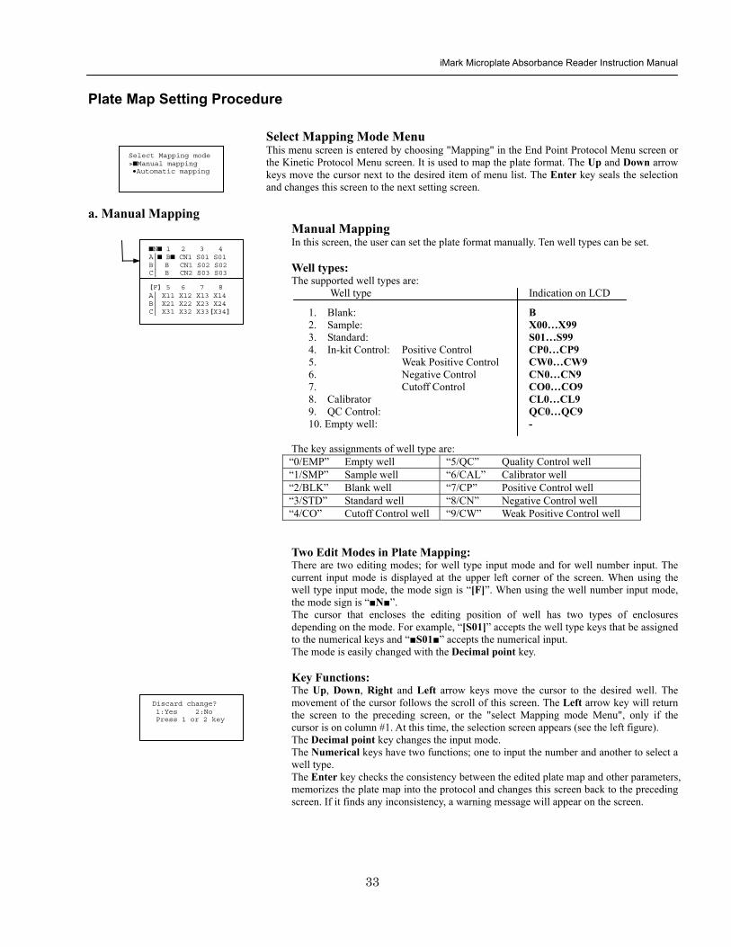
iMark Microplate Absorbance Reader Instruction Manual
34
Acceptable Number Ranges for each well type 1 Blank and Empty wells do not use numbers 2 Sample and Standard wells 00 - 99 3 Standard wells 01 - 99 4 Control and Calibrator wells 0 - 9
b Automatic Mapping
Automatic Mapping The user can input the number of each well type in this screen These defined numbers are used to set a plate map automatically Well type Nine well types are available
1 BLK Blank (0-gt10) 2 CN Control CN (0-gt9) 3 CW Control CW (0-gt9) 4 CP Control CP (0-gt9) 5 CO Control CO (0-gt9) 6 QC Control QC (0-gt9) 7 CAL Calibrator (0-gt9) 8 SMP Sample (0-gt96) 9 REP Replicate well (1-gt4)
It is possible to define the number of blanks samples calibrators and controls But the number of Standards is not included because standards are defined at the Standard Setting Menu The number of replicate wells is also included It is used for replicating each well type individually Key Functions The Up Down Right and Left arrow keys are used to move the cursor to the next position The Numerical keys are used to input the mapping parameters The Enter key accepts the mapping parameters and sets a plate map automatically using these parameters During the execution of the plate mapping the Plate auto-mapping completed message appears on the screen After that the user returns automatically to the previous Protocol Menu screen If the Left arrow key is pressed at the left end position of the cursor the left figure will appear on the screen If the user chooses Yes the system will return to the previous Protocol Menu screen If the user chooses No the system will stay in this setting screen Assigning Order and Direction of plate mapping Assigning Order The order of blanks standards samples calibrators and controls are fixed as follows Numbering for standards samples calibrators and controls is started at 1
1 Blank 2 Standard 1 -gt12 ---- NOTE 3 Control CN 1-gt9 4 Control CW 1-gt9 5 Control CP 1-gt9 6 Control CO 1-gt9 7 Control QC 1-gt9 8 Calibrator 1-gt9 9 Sample 1-gt96 10 Empty well NOTE If ldquoCutoff Controlrdquo ldquoValue by Formulardquo or ldquoRatio to Calibratorrdquo is
selected for the Cutoff plate mapping skips arranging the standards Assigning Direction The placing direction of the mapping is limited to the column direction as below
Column direction A1 -gt H1 A2 -gt H2 ----- A12 -gt H12
Discard change 1Yes 2No Press 1 or 2 key
Automatic mapping BLK= 1 CP = 1 CAL= 0 CN = 1 CO = 0 SMP=93 CW = 0 QC = 0 REP= 1
Plate auto-mapping completed
iMark Microplate Absorbance Reader Instruction Manual
35
Warning and Error of Automatic Mapping Warning screen If the total number of wells mapped exceeds 96 wells a warning message in the left figure appears on the screen The calculation of the total number of mapping wells is as follows
(Blanks+Standards+CNs+CWs+CPs+COs+QCs+Calibrators+Sample)Replicates The plate mapping is executed normally and the exceeded part is invalidated Error screen If one or more mapping parameters are over the input range an error message in the left figure will appear on the screen On the third line of the LCD the name of the parameter which is out of range and its input range will appear
Example ldquoBLK 0 ndash 10rdquo In case there is more than one error the first parameter of errors is indicated By pressing any key the user returns to the automatic mapping screen Example of automatic mapping An example of automatic mapping is as below 1 Conditions of each parameter
Blank = 1 Standard = 8 Control CN = 2 CW = 0 CP = 2 CO = 0 QC = 0 Calibrator = 1 Sample = 32 Replicate number = 2
2 Plate mapping data
1 2 3 4 5 6 7 8 9 10 11 12 A B C D E F G H
B B S1 S1 S2 S2 S3 S3
S4 S4 S5 S5 S6 S6 S7 S7
S8 S8 CN1 CN1 CN2 CN2 CP1 CP1
CP2 CP2 CL1 CL1 X1 X1 X2 X2
X3 X3 X4 X4 X5 X5 X6 X6
X7 X7 X8 X8 X9 X9 X10 X10
X11 X11 X12 X12 X13 X13 X14 X14
X15 X15 X16 X16 X17 X17 X18 X18
X19 X19 X20 X20 X21 X21 X22 X22
X23 X23 X24 X24 X25 X25 X26 X26
X27 X27 X28 X28 X29 X29 X30 X30
X31 X31 X32 X32 E E E E
Warning The total Of mapped wells has Exceeded 96 Press any key
Entered value is Out of range BLK 0 ndash 10 Press any key
iMark Microplate Absorbance Reader Instruction Manual
36
Instrument Maintenance
Caution Electrical shock hazard Always disconnect the instrument from the AC power source before opening the service compartment
Caution The lamp and the lamp cover may be very hot Use caution and allow the lamp to cool
before attempting service
Installing Interference Filters 1 With the power off open the rear cover of the instrument by pressing the
release latch located on the top left portion of the cover 2 Locate the filter wheel on the left side of the instrument Note that the
filter wheel has eight filter positions 3 Rotate the filter wheel to the desired filter Grasp the top of filter frame
and pull up to remove the filter 4 Insert the new filter into the desired filter position 5 Ensure that the new filter is added to the filter list as follows Main
menu-gtEdit-gtFilters
Changing the Lamp 1 With the power off open the rear cover of the instrument by pressing the
release latch located on the top left portion of the cover 2 Remove the two screws on the black plastic cover and carefully remove
the plastic cover 3 Remove the screw on the metal cover Lift the cover up and away from
the instrument This will allow the lamp to be pulled free from the lamp housing
4 Holding the ceramic base in one hand and the lamp housing in the other carefully pull the lamp free of the base
5 Carefully insert the new lamp firmly in the ceramic base Apply even pressure when inserting the lamp so that the bulb dose not become misaligned in the reflector housing Be extremely careful not to touch the front glass of the lamp during installation
6 Position the new lamp into the housing so that the plastic guides hold the flange of the lamp
7 Carefully place the metal cover over the lamp Tighten the screw 8 Replace the plastic cover and tighten the screws 9 Close the rear cover
iMark Microplate Absorbance Reader Instruction Manual
37
Troubleshooting and Error Messages
The iMark Microplate Reader constantly monitors several functions and displays appropriate messages on the LCD as errors are encountered
Error Recommendation
LCD appears blank on power up
a Power is not turned on The AC outlet is non-functional
b Unit is not plugged into AC outlet or power code is not attached to the instrument
Check power cord connections at outlet and on the rear panel of the instrument
1
c The AC outlet is non-functional Check circuit breakers or fuses
Instrument displays ldquoLight bulb errorrdquo message indicating that the bulb is burned out
Check whether lamp is emitting light
a Lamp is not emitting light Replace the lamp as described in x
2
b Lamp is emitting light Check the alignment of the lamp in the housing Align or replace the lamp if necessary
Printer will not print on command
3
a Printer paper is not installed properly Verify that the paper is properly installed Refer to x for details
Plate carriage jams during reading and ldquoPlate carrier errorrdquo is displayed
a Plate is not seated in carriage properly Press the STOP button immediately Position the plate carefully in the carriage making certain that it is properly seated
4
b Plate height is exceeding 16mm Use Microplate which is less than 16mm in height
5 LCD displays ldquoFilter missingrdquo Install a filter in the empty position Select the installed filter by pressing Edit key
6 LCD displays ldquoFilter disk jammedrdquo indicating that the filter wheel is not turning freely
Turn off the instrument and inspect the filter wheel Turn by hand to verify that the wheel is moving freely Make sure all the filters are properly installed and firmly seated Contact your Bio-Rad representative if the filter wheel is jammed or if the problem persists
7 LCD displays ldquoFilter not installedrdquo Enter the Edit Menu by pressing Edit key and set up the filters
iMark Microplate Absorbance Reader Instruction Manual
38
Wells have color but absorbance values seem low
a Incorrect filter used for measurement andor reference wavelength
Check wavelength used in analysis Read plate in single wavelength mode at all wavelength to verify that the proper filter was used The measurement wavelength should produce the highest absorbance
b The best measurement wavelength filter for the substrate in use has not been installed in the filter wheel
Check references for the substrate you are using or determine the best measurement wavelength by analyzing the substrate product on a scanning spectrophotometer Custom filters are available from 400 to 750 nm
8
c The filters have been switched in the wheel Check that the filters are installed in the correct position
9 ldquoPrinter errorrdquo displayed Check for paper jam Install the printer paper correctly
10 ldquoBattery errorrdquo displayed The internal battery is almost dead Contact your local Bio-Rad office
11 The following messages are displayed ldquoMemory errorrdquo ldquoCalendar errorrdquo ldquoLCD hardware errorrdquo ldquoPrinter errorrdquo ldquoLight level errorrdquo ldquoDA conversion errorrdquo ldquoAD conversion errorrdquo ldquoEEPROM errorrdquo ldquoUSB errorrdquo
Contact your local Bio-Rad office if these problems persist
iMark Microplate Absorbance Reader Instruction Manual
39
Instrument Specifications Computer interface USB 20
Plate shaking 3 speeds (low mid high) Programmable time period 0 - 999 seconds
Data storage The most recent 10 data plates for end-point most recent 2 data plates of 30 readings for kinetic readings protocol data and calendarclock function shall be kept in memory by a lithium battery even when the power is off Average lifetime of the battery shall be 5 years
Warm-up time 3 minutes
Photometric Methods Single and dual wavelength
Photo detectors 8 silicon photodiodes for measurement and 1 silicon photodiode for reference
Light source Tungsten halogen lamp 20W with 3000 hours average lifetime
Spectral range 400 nm to 750 nm
Interference filters Wavelength tolerance plusmn30 nm Band width 10 nm typically
Filter capacity 8 filters
Reading speed Fast Reading 6 sec with single wavelength reading 10 sec with dual wavelength reading
Step Reading 15 sec with single wavelength reading 25 sec with dual wavelength reading
These times are minimum interval times between repetitive reads using onboard KINETIC protocol
Indication range 0000 to 35 OD
Resolution 0001 OD
Accuracy plusmn10 or 0010 from 0 to 30 OD at 490 nm
Linearity plusmn10 from 0 to 20 OD plusmn20 from 0 to 30 OD
Reproducibility 10 or 0005 OD from 0 to 20 OD 15 from 20 to 30 OD
Inter-channel variability 15 or 0005 OD from 0 to 30 OD
Stability and Drift 0010 OD at OD=1 with single wavelength reading
Built-in Printer Thermal printer Paper width 80mm
Line Voltage Universal input 100 - 240 VAC 5060Hz
Power consumption (max) 100 VA max
Dimensions (W x D x H 346 mm x 377 mm x 164 m mm
Weight 55 kg
Operating Environment 15ordmC - 40ordmC up to 90 relative humidity without condensation
Storage Temperature 10ordmC - 50ordmC up to 90 relative humidity without condensation
Life ScienceGroup
07-0816 0108 Sig 120710013301i Rev A USEG
Bio-RadLaboratories Inc
Web site wwwbio-radcom USA 800 4BIORAD Australia 61 02 9914 2800 Austria 01 877 89 01 Belgium 09 385 55 11 Brazil 55 21 3237 9400 Canada 905 364 3435 China 86 21 6426 0808 Czech Republic 420 241 430 532 Denmark 44 52 10 00 Finland 09 804 22 00 France 01 47 95 69 65Germany 089 318 84 0 Greece 30 210 777 4396 Hong Kong 852 2789 3300 Hungary 36 1 455 8800 India 91 124 4029300 Israel 03 963 6050 Italy 39 02 216091 Japan 03 6361 7000 Korea 82 2 3473 4460 Mexico 52 555 488 7670 The Netherlands 0318 540666 New Zealand 0508 805 500 Norway 23 38 41 30 Poland 48 22 331 99 99 Portugal 351 21 472 7700 Russia 7 495 721 14 04 Singapore 65 6415 3188 South Africa 27 861 246 723 Spain 34 91 590 5200 Sweden 08 555 12700 Switzerland 061 717 95 55 Taiwan 886 2 2578 7189 United Kingdom 020 8328 2000
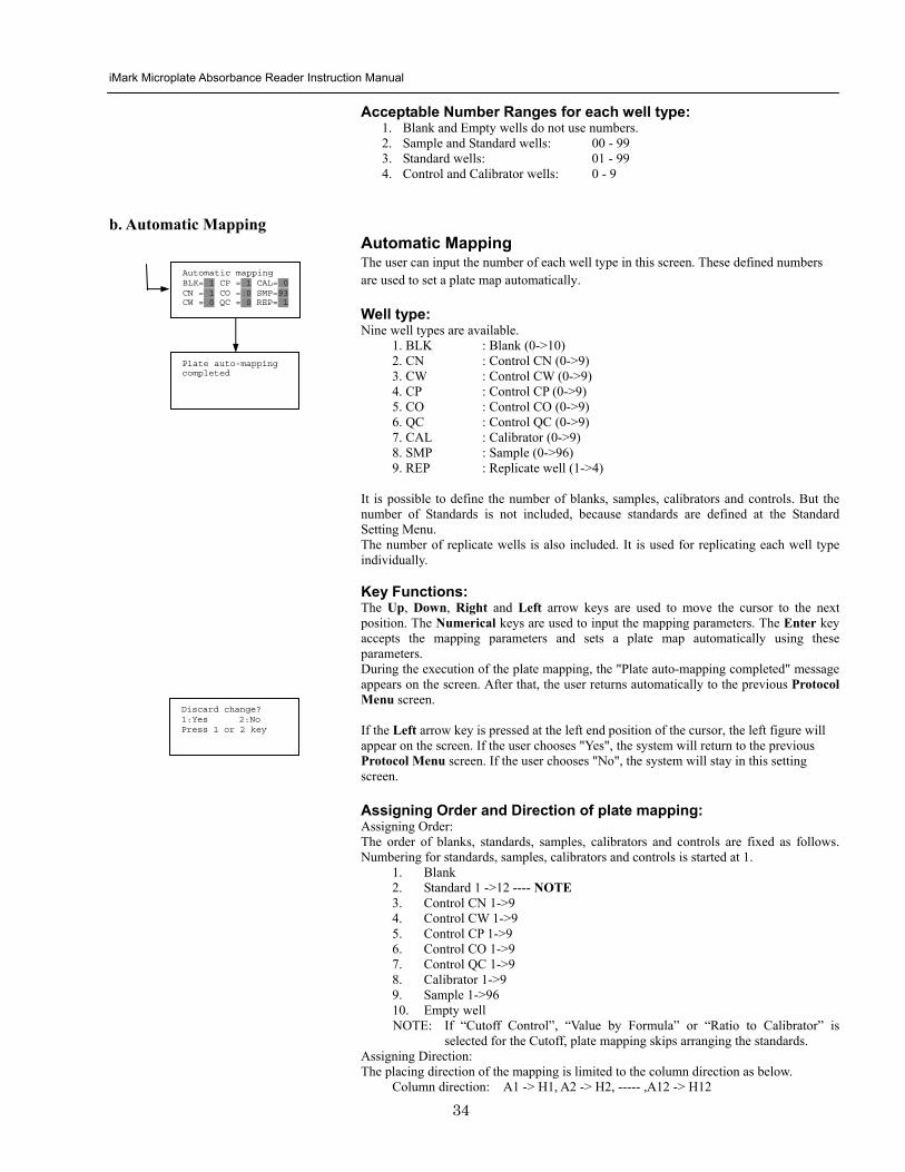
iMark Microplate Absorbance Reader Instruction Manual
35
Warning and Error of Automatic Mapping Warning screen If the total number of wells mapped exceeds 96 wells a warning message in the left figure appears on the screen The calculation of the total number of mapping wells is as follows
(Blanks+Standards+CNs+CWs+CPs+COs+QCs+Calibrators+Sample)Replicates The plate mapping is executed normally and the exceeded part is invalidated Error screen If one or more mapping parameters are over the input range an error message in the left figure will appear on the screen On the third line of the LCD the name of the parameter which is out of range and its input range will appear
Example ldquoBLK 0 ndash 10rdquo In case there is more than one error the first parameter of errors is indicated By pressing any key the user returns to the automatic mapping screen Example of automatic mapping An example of automatic mapping is as below 1 Conditions of each parameter
Blank = 1 Standard = 8 Control CN = 2 CW = 0 CP = 2 CO = 0 QC = 0 Calibrator = 1 Sample = 32 Replicate number = 2
2 Plate mapping data
1 2 3 4 5 6 7 8 9 10 11 12 A B C D E F G H
B B S1 S1 S2 S2 S3 S3
S4 S4 S5 S5 S6 S6 S7 S7
S8 S8 CN1 CN1 CN2 CN2 CP1 CP1
CP2 CP2 CL1 CL1 X1 X1 X2 X2
X3 X3 X4 X4 X5 X5 X6 X6
X7 X7 X8 X8 X9 X9 X10 X10
X11 X11 X12 X12 X13 X13 X14 X14
X15 X15 X16 X16 X17 X17 X18 X18
X19 X19 X20 X20 X21 X21 X22 X22
X23 X23 X24 X24 X25 X25 X26 X26
X27 X27 X28 X28 X29 X29 X30 X30
X31 X31 X32 X32 E E E E
Warning The total Of mapped wells has Exceeded 96 Press any key
Entered value is Out of range BLK 0 ndash 10 Press any key
iMark Microplate Absorbance Reader Instruction Manual
36
Instrument Maintenance
Caution Electrical shock hazard Always disconnect the instrument from the AC power source before opening the service compartment
Caution The lamp and the lamp cover may be very hot Use caution and allow the lamp to cool
before attempting service
Installing Interference Filters 1 With the power off open the rear cover of the instrument by pressing the
release latch located on the top left portion of the cover 2 Locate the filter wheel on the left side of the instrument Note that the
filter wheel has eight filter positions 3 Rotate the filter wheel to the desired filter Grasp the top of filter frame
and pull up to remove the filter 4 Insert the new filter into the desired filter position 5 Ensure that the new filter is added to the filter list as follows Main
menu-gtEdit-gtFilters
Changing the Lamp 1 With the power off open the rear cover of the instrument by pressing the
release latch located on the top left portion of the cover 2 Remove the two screws on the black plastic cover and carefully remove
the plastic cover 3 Remove the screw on the metal cover Lift the cover up and away from
the instrument This will allow the lamp to be pulled free from the lamp housing
4 Holding the ceramic base in one hand and the lamp housing in the other carefully pull the lamp free of the base
5 Carefully insert the new lamp firmly in the ceramic base Apply even pressure when inserting the lamp so that the bulb dose not become misaligned in the reflector housing Be extremely careful not to touch the front glass of the lamp during installation
6 Position the new lamp into the housing so that the plastic guides hold the flange of the lamp
7 Carefully place the metal cover over the lamp Tighten the screw 8 Replace the plastic cover and tighten the screws 9 Close the rear cover
iMark Microplate Absorbance Reader Instruction Manual
37
Troubleshooting and Error Messages
The iMark Microplate Reader constantly monitors several functions and displays appropriate messages on the LCD as errors are encountered
Error Recommendation
LCD appears blank on power up
a Power is not turned on The AC outlet is non-functional
b Unit is not plugged into AC outlet or power code is not attached to the instrument
Check power cord connections at outlet and on the rear panel of the instrument
1
c The AC outlet is non-functional Check circuit breakers or fuses
Instrument displays ldquoLight bulb errorrdquo message indicating that the bulb is burned out
Check whether lamp is emitting light
a Lamp is not emitting light Replace the lamp as described in x
2
b Lamp is emitting light Check the alignment of the lamp in the housing Align or replace the lamp if necessary
Printer will not print on command
3
a Printer paper is not installed properly Verify that the paper is properly installed Refer to x for details
Plate carriage jams during reading and ldquoPlate carrier errorrdquo is displayed
a Plate is not seated in carriage properly Press the STOP button immediately Position the plate carefully in the carriage making certain that it is properly seated
4
b Plate height is exceeding 16mm Use Microplate which is less than 16mm in height
5 LCD displays ldquoFilter missingrdquo Install a filter in the empty position Select the installed filter by pressing Edit key
6 LCD displays ldquoFilter disk jammedrdquo indicating that the filter wheel is not turning freely
Turn off the instrument and inspect the filter wheel Turn by hand to verify that the wheel is moving freely Make sure all the filters are properly installed and firmly seated Contact your Bio-Rad representative if the filter wheel is jammed or if the problem persists
7 LCD displays ldquoFilter not installedrdquo Enter the Edit Menu by pressing Edit key and set up the filters
iMark Microplate Absorbance Reader Instruction Manual
38
Wells have color but absorbance values seem low
a Incorrect filter used for measurement andor reference wavelength
Check wavelength used in analysis Read plate in single wavelength mode at all wavelength to verify that the proper filter was used The measurement wavelength should produce the highest absorbance
b The best measurement wavelength filter for the substrate in use has not been installed in the filter wheel
Check references for the substrate you are using or determine the best measurement wavelength by analyzing the substrate product on a scanning spectrophotometer Custom filters are available from 400 to 750 nm
8
c The filters have been switched in the wheel Check that the filters are installed in the correct position
9 ldquoPrinter errorrdquo displayed Check for paper jam Install the printer paper correctly
10 ldquoBattery errorrdquo displayed The internal battery is almost dead Contact your local Bio-Rad office
11 The following messages are displayed ldquoMemory errorrdquo ldquoCalendar errorrdquo ldquoLCD hardware errorrdquo ldquoPrinter errorrdquo ldquoLight level errorrdquo ldquoDA conversion errorrdquo ldquoAD conversion errorrdquo ldquoEEPROM errorrdquo ldquoUSB errorrdquo
Contact your local Bio-Rad office if these problems persist
iMark Microplate Absorbance Reader Instruction Manual
39
Instrument Specifications Computer interface USB 20
Plate shaking 3 speeds (low mid high) Programmable time period 0 - 999 seconds
Data storage The most recent 10 data plates for end-point most recent 2 data plates of 30 readings for kinetic readings protocol data and calendarclock function shall be kept in memory by a lithium battery even when the power is off Average lifetime of the battery shall be 5 years
Warm-up time 3 minutes
Photometric Methods Single and dual wavelength
Photo detectors 8 silicon photodiodes for measurement and 1 silicon photodiode for reference
Light source Tungsten halogen lamp 20W with 3000 hours average lifetime
Spectral range 400 nm to 750 nm
Interference filters Wavelength tolerance plusmn30 nm Band width 10 nm typically
Filter capacity 8 filters
Reading speed Fast Reading 6 sec with single wavelength reading 10 sec with dual wavelength reading
Step Reading 15 sec with single wavelength reading 25 sec with dual wavelength reading
These times are minimum interval times between repetitive reads using onboard KINETIC protocol
Indication range 0000 to 35 OD
Resolution 0001 OD
Accuracy plusmn10 or 0010 from 0 to 30 OD at 490 nm
Linearity plusmn10 from 0 to 20 OD plusmn20 from 0 to 30 OD
Reproducibility 10 or 0005 OD from 0 to 20 OD 15 from 20 to 30 OD
Inter-channel variability 15 or 0005 OD from 0 to 30 OD
Stability and Drift 0010 OD at OD=1 with single wavelength reading
Built-in Printer Thermal printer Paper width 80mm
Line Voltage Universal input 100 - 240 VAC 5060Hz
Power consumption (max) 100 VA max
Dimensions (W x D x H 346 mm x 377 mm x 164 m mm
Weight 55 kg
Operating Environment 15ordmC - 40ordmC up to 90 relative humidity without condensation
Storage Temperature 10ordmC - 50ordmC up to 90 relative humidity without condensation
Life ScienceGroup
07-0816 0108 Sig 120710013301i Rev A USEG
Bio-RadLaboratories Inc
Web site wwwbio-radcom USA 800 4BIORAD Australia 61 02 9914 2800 Austria 01 877 89 01 Belgium 09 385 55 11 Brazil 55 21 3237 9400 Canada 905 364 3435 China 86 21 6426 0808 Czech Republic 420 241 430 532 Denmark 44 52 10 00 Finland 09 804 22 00 France 01 47 95 69 65Germany 089 318 84 0 Greece 30 210 777 4396 Hong Kong 852 2789 3300 Hungary 36 1 455 8800 India 91 124 4029300 Israel 03 963 6050 Italy 39 02 216091 Japan 03 6361 7000 Korea 82 2 3473 4460 Mexico 52 555 488 7670 The Netherlands 0318 540666 New Zealand 0508 805 500 Norway 23 38 41 30 Poland 48 22 331 99 99 Portugal 351 21 472 7700 Russia 7 495 721 14 04 Singapore 65 6415 3188 South Africa 27 861 246 723 Spain 34 91 590 5200 Sweden 08 555 12700 Switzerland 061 717 95 55 Taiwan 886 2 2578 7189 United Kingdom 020 8328 2000
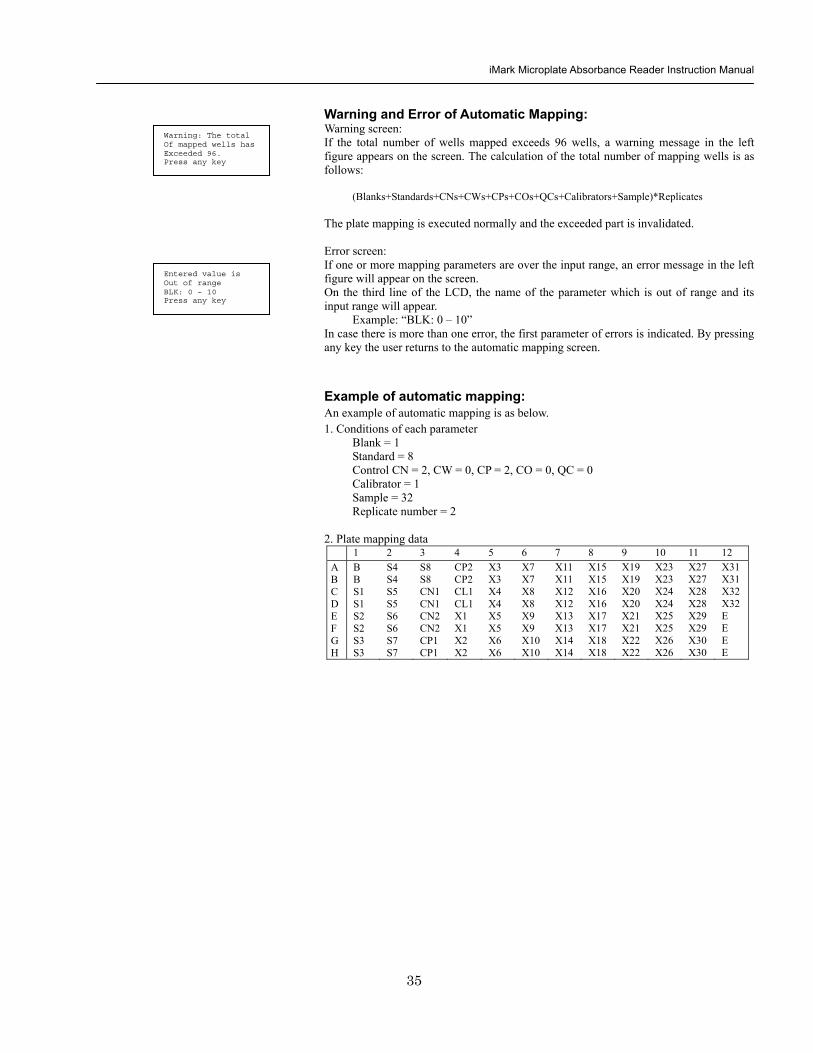
iMark Microplate Absorbance Reader Instruction Manual
36
Instrument Maintenance
Caution Electrical shock hazard Always disconnect the instrument from the AC power source before opening the service compartment
Caution The lamp and the lamp cover may be very hot Use caution and allow the lamp to cool
before attempting service
Installing Interference Filters 1 With the power off open the rear cover of the instrument by pressing the
release latch located on the top left portion of the cover 2 Locate the filter wheel on the left side of the instrument Note that the
filter wheel has eight filter positions 3 Rotate the filter wheel to the desired filter Grasp the top of filter frame
and pull up to remove the filter 4 Insert the new filter into the desired filter position 5 Ensure that the new filter is added to the filter list as follows Main
menu-gtEdit-gtFilters
Changing the Lamp 1 With the power off open the rear cover of the instrument by pressing the
release latch located on the top left portion of the cover 2 Remove the two screws on the black plastic cover and carefully remove
the plastic cover 3 Remove the screw on the metal cover Lift the cover up and away from
the instrument This will allow the lamp to be pulled free from the lamp housing
4 Holding the ceramic base in one hand and the lamp housing in the other carefully pull the lamp free of the base
5 Carefully insert the new lamp firmly in the ceramic base Apply even pressure when inserting the lamp so that the bulb dose not become misaligned in the reflector housing Be extremely careful not to touch the front glass of the lamp during installation
6 Position the new lamp into the housing so that the plastic guides hold the flange of the lamp
7 Carefully place the metal cover over the lamp Tighten the screw 8 Replace the plastic cover and tighten the screws 9 Close the rear cover
iMark Microplate Absorbance Reader Instruction Manual
37
Troubleshooting and Error Messages
The iMark Microplate Reader constantly monitors several functions and displays appropriate messages on the LCD as errors are encountered
Error Recommendation
LCD appears blank on power up
a Power is not turned on The AC outlet is non-functional
b Unit is not plugged into AC outlet or power code is not attached to the instrument
Check power cord connections at outlet and on the rear panel of the instrument
1
c The AC outlet is non-functional Check circuit breakers or fuses
Instrument displays ldquoLight bulb errorrdquo message indicating that the bulb is burned out
Check whether lamp is emitting light
a Lamp is not emitting light Replace the lamp as described in x
2
b Lamp is emitting light Check the alignment of the lamp in the housing Align or replace the lamp if necessary
Printer will not print on command
3
a Printer paper is not installed properly Verify that the paper is properly installed Refer to x for details
Plate carriage jams during reading and ldquoPlate carrier errorrdquo is displayed
a Plate is not seated in carriage properly Press the STOP button immediately Position the plate carefully in the carriage making certain that it is properly seated
4
b Plate height is exceeding 16mm Use Microplate which is less than 16mm in height
5 LCD displays ldquoFilter missingrdquo Install a filter in the empty position Select the installed filter by pressing Edit key
6 LCD displays ldquoFilter disk jammedrdquo indicating that the filter wheel is not turning freely
Turn off the instrument and inspect the filter wheel Turn by hand to verify that the wheel is moving freely Make sure all the filters are properly installed and firmly seated Contact your Bio-Rad representative if the filter wheel is jammed or if the problem persists
7 LCD displays ldquoFilter not installedrdquo Enter the Edit Menu by pressing Edit key and set up the filters
iMark Microplate Absorbance Reader Instruction Manual
38
Wells have color but absorbance values seem low
a Incorrect filter used for measurement andor reference wavelength
Check wavelength used in analysis Read plate in single wavelength mode at all wavelength to verify that the proper filter was used The measurement wavelength should produce the highest absorbance
b The best measurement wavelength filter for the substrate in use has not been installed in the filter wheel
Check references for the substrate you are using or determine the best measurement wavelength by analyzing the substrate product on a scanning spectrophotometer Custom filters are available from 400 to 750 nm
8
c The filters have been switched in the wheel Check that the filters are installed in the correct position
9 ldquoPrinter errorrdquo displayed Check for paper jam Install the printer paper correctly
10 ldquoBattery errorrdquo displayed The internal battery is almost dead Contact your local Bio-Rad office
11 The following messages are displayed ldquoMemory errorrdquo ldquoCalendar errorrdquo ldquoLCD hardware errorrdquo ldquoPrinter errorrdquo ldquoLight level errorrdquo ldquoDA conversion errorrdquo ldquoAD conversion errorrdquo ldquoEEPROM errorrdquo ldquoUSB errorrdquo
Contact your local Bio-Rad office if these problems persist
iMark Microplate Absorbance Reader Instruction Manual
39
Instrument Specifications Computer interface USB 20
Plate shaking 3 speeds (low mid high) Programmable time period 0 - 999 seconds
Data storage The most recent 10 data plates for end-point most recent 2 data plates of 30 readings for kinetic readings protocol data and calendarclock function shall be kept in memory by a lithium battery even when the power is off Average lifetime of the battery shall be 5 years
Warm-up time 3 minutes
Photometric Methods Single and dual wavelength
Photo detectors 8 silicon photodiodes for measurement and 1 silicon photodiode for reference
Light source Tungsten halogen lamp 20W with 3000 hours average lifetime
Spectral range 400 nm to 750 nm
Interference filters Wavelength tolerance plusmn30 nm Band width 10 nm typically
Filter capacity 8 filters
Reading speed Fast Reading 6 sec with single wavelength reading 10 sec with dual wavelength reading
Step Reading 15 sec with single wavelength reading 25 sec with dual wavelength reading
These times are minimum interval times between repetitive reads using onboard KINETIC protocol
Indication range 0000 to 35 OD
Resolution 0001 OD
Accuracy plusmn10 or 0010 from 0 to 30 OD at 490 nm
Linearity plusmn10 from 0 to 20 OD plusmn20 from 0 to 30 OD
Reproducibility 10 or 0005 OD from 0 to 20 OD 15 from 20 to 30 OD
Inter-channel variability 15 or 0005 OD from 0 to 30 OD
Stability and Drift 0010 OD at OD=1 with single wavelength reading
Built-in Printer Thermal printer Paper width 80mm
Line Voltage Universal input 100 - 240 VAC 5060Hz
Power consumption (max) 100 VA max
Dimensions (W x D x H 346 mm x 377 mm x 164 m mm
Weight 55 kg
Operating Environment 15ordmC - 40ordmC up to 90 relative humidity without condensation
Storage Temperature 10ordmC - 50ordmC up to 90 relative humidity without condensation
Life ScienceGroup
07-0816 0108 Sig 120710013301i Rev A USEG
Bio-RadLaboratories Inc
Web site wwwbio-radcom USA 800 4BIORAD Australia 61 02 9914 2800 Austria 01 877 89 01 Belgium 09 385 55 11 Brazil 55 21 3237 9400 Canada 905 364 3435 China 86 21 6426 0808 Czech Republic 420 241 430 532 Denmark 44 52 10 00 Finland 09 804 22 00 France 01 47 95 69 65Germany 089 318 84 0 Greece 30 210 777 4396 Hong Kong 852 2789 3300 Hungary 36 1 455 8800 India 91 124 4029300 Israel 03 963 6050 Italy 39 02 216091 Japan 03 6361 7000 Korea 82 2 3473 4460 Mexico 52 555 488 7670 The Netherlands 0318 540666 New Zealand 0508 805 500 Norway 23 38 41 30 Poland 48 22 331 99 99 Portugal 351 21 472 7700 Russia 7 495 721 14 04 Singapore 65 6415 3188 South Africa 27 861 246 723 Spain 34 91 590 5200 Sweden 08 555 12700 Switzerland 061 717 95 55 Taiwan 886 2 2578 7189 United Kingdom 020 8328 2000
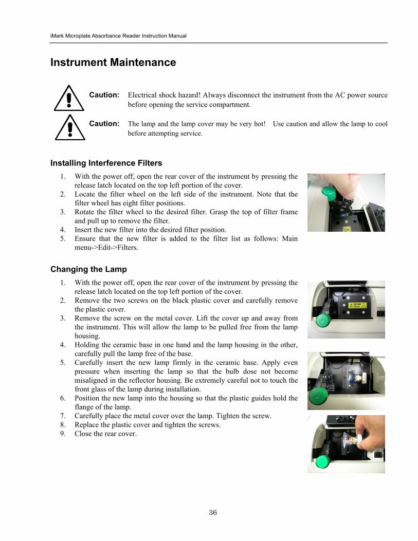
iMark Microplate Absorbance Reader Instruction Manual
39
Instrument Specifications Computer interface USB 20
Plate shaking 3 speeds (low mid high) Programmable time period 0 - 999 seconds
Data storage The most recent 10 data plates for end-point most recent 2 data plates of 30 readings for kinetic readings protocol data and calendarclock function shall be kept in memory by a lithium battery even when the power is off Average lifetime of the battery shall be 5 years
Warm-up time 3 minutes
Photometric Methods Single and dual wavelength
Photo detectors 8 silicon photodiodes for measurement and 1 silicon photodiode for reference
Light source Tungsten halogen lamp 20W with 3000 hours average lifetime
Spectral range 400 nm to 750 nm
Interference filters Wavelength tolerance plusmn30 nm Band width 10 nm typically
Filter capacity 8 filters
Reading speed Fast Reading 6 sec with single wavelength reading 10 sec with dual wavelength reading
Step Reading 15 sec with single wavelength reading 25 sec with dual wavelength reading
These times are minimum interval times between repetitive reads using onboard KINETIC protocol
Indication range 0000 to 35 OD
Resolution 0001 OD
Accuracy plusmn10 or 0010 from 0 to 30 OD at 490 nm
Linearity plusmn10 from 0 to 20 OD plusmn20 from 0 to 30 OD
Reproducibility 10 or 0005 OD from 0 to 20 OD 15 from 20 to 30 OD
Inter-channel variability 15 or 0005 OD from 0 to 30 OD
Stability and Drift 0010 OD at OD=1 with single wavelength reading
Built-in Printer Thermal printer Paper width 80mm
Line Voltage Universal input 100 - 240 VAC 5060Hz
Power consumption (max) 100 VA max
Dimensions (W x D x H 346 mm x 377 mm x 164 m mm
Weight 55 kg
Operating Environment 15ordmC - 40ordmC up to 90 relative humidity without condensation
Storage Temperature 10ordmC - 50ordmC up to 90 relative humidity without condensation
Life ScienceGroup
07-0816 0108 Sig 120710013301i Rev A USEG
Bio-RadLaboratories Inc
Web site wwwbio-radcom USA 800 4BIORAD Australia 61 02 9914 2800 Austria 01 877 89 01 Belgium 09 385 55 11 Brazil 55 21 3237 9400 Canada 905 364 3435 China 86 21 6426 0808 Czech Republic 420 241 430 532 Denmark 44 52 10 00 Finland 09 804 22 00 France 01 47 95 69 65Germany 089 318 84 0 Greece 30 210 777 4396 Hong Kong 852 2789 3300 Hungary 36 1 455 8800 India 91 124 4029300 Israel 03 963 6050 Italy 39 02 216091 Japan 03 6361 7000 Korea 82 2 3473 4460 Mexico 52 555 488 7670 The Netherlands 0318 540666 New Zealand 0508 805 500 Norway 23 38 41 30 Poland 48 22 331 99 99 Portugal 351 21 472 7700 Russia 7 495 721 14 04 Singapore 65 6415 3188 South Africa 27 861 246 723 Spain 34 91 590 5200 Sweden 08 555 12700 Switzerland 061 717 95 55 Taiwan 886 2 2578 7189 United Kingdom 020 8328 2000
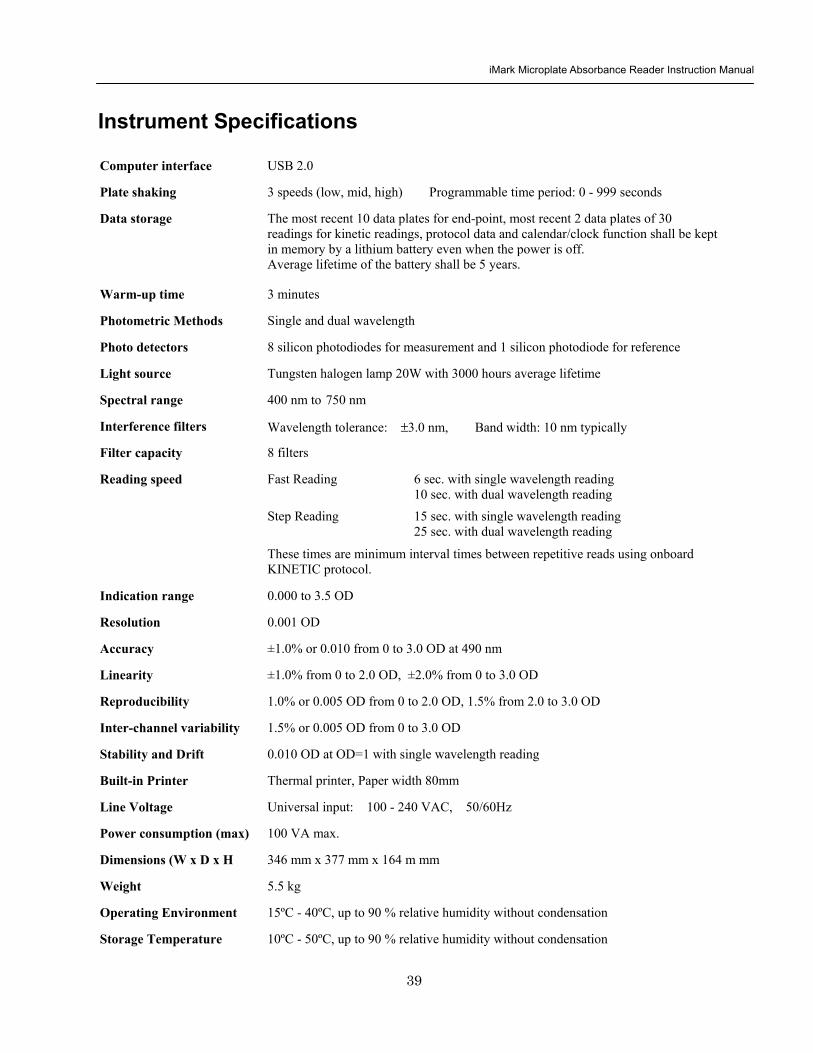