Embed Size (px)
Citation preview
8 n APPLIED RADIOLOGY©
www.appliedradiology.com January 2017
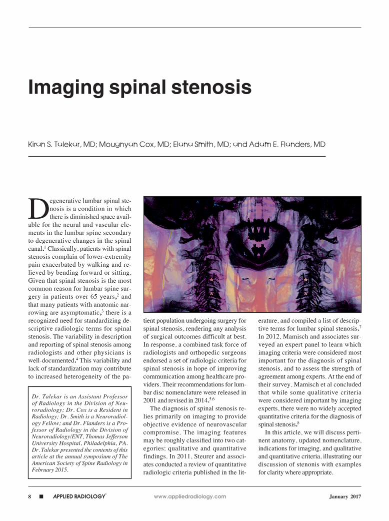
Degenerative lumbar spinal ste-nosis is a condition in which there is diminished space avail-
able for the neural and vascular ele-ments in the lumbar spine secondary to degenerative changes in the spinal canal.1 Classically, patients with spinal stenosis complain of lower-extremity pain exacerbated by walking and re-lieved by bending forward or sitting. Given that spinal stenosis is the most common reason for lumbar spine sur-gery in patients over 65 years,2 and that many patients with anatomic nar-rowing are asymptomatic,3 there is a recognized need for standardizing de-scriptive radiologic terms for spinal stenosis. The variability in description and reporting of spinal stenosis among radiologists and other physicians is well-documented.4 This variability and lack of standardization may contribute to increased heterogeneity of the pa-
tient population undergoing surgery for spinal stenosis, rendering any analysis of surgical outcomes difficult at best. In response, a combined task force of radiologists and orthopedic surgeons endorsed a set of radiologic criteria for spinal stenosis in hope of improving communication among healthcare pro-viders. Their recommendations for lum-bar disc nomenclature were released in 2001 and revised in 2014.5,6
The diagnosis of spinal stenosis re-lies primarily on imaging to provide objective evidence of neurovascular compromise. The imaging features may be roughly classified into two cat-egories; qualitative and quantitative findings. In 2011, Steurer and associ-ates conducted a review of quantitative radiologic criteria published in the lit-
erature, and compiled a list of descrip-tive terms for lumbar spinal stenosis.7 In 2012, Mamisch and associates sur-veyed an expert panel to learn which imaging criteria were considered most important for the diagnosis of spinal stenosis, and to assess the strength of agreement among experts. At the end of their survey, Mamisch et al concluded that while some qualitative criteria were considered important by imaging experts, there were no widely accepted quantitative criteria for the diagnosis of spinal stenosis.8
In this article, we will discuss perti-nent anatomy, updated nomenclature, indications for imaging, and qualitative and quantitative criteria, illustrating our discussion of stenonis with examples for clarity where appropriate.
Imaging spinal stenosis
Kiran S. Talekar, MD; Mougnyan Cox, MD; Elana Smith, MD; and Adam E. Flanders, MD
Dr. Talekar is an Assistant Professor of Radiology in the Division of Neu-roradiology; Dr. Cox is a Resident in Radiology; Dr. Smith is a Neuroradiol-ogy Fellow; and Dr. Flanders is a Pro-fessor of Radiology in the Division of Neuroradiology/ENT, Thomas Jefferson University Hospital, Philadelphia, PA. Dr. Talekar presented the contents of this article at the annual symposium of The American Society of Spine Radiology in February 2015.

www.appliedradiology.com APPLIED RADIOLOGY©
n 9January 2017
IMAGING SPINAL STENOSIS
Anatomy, nomenclature, and the combined task force
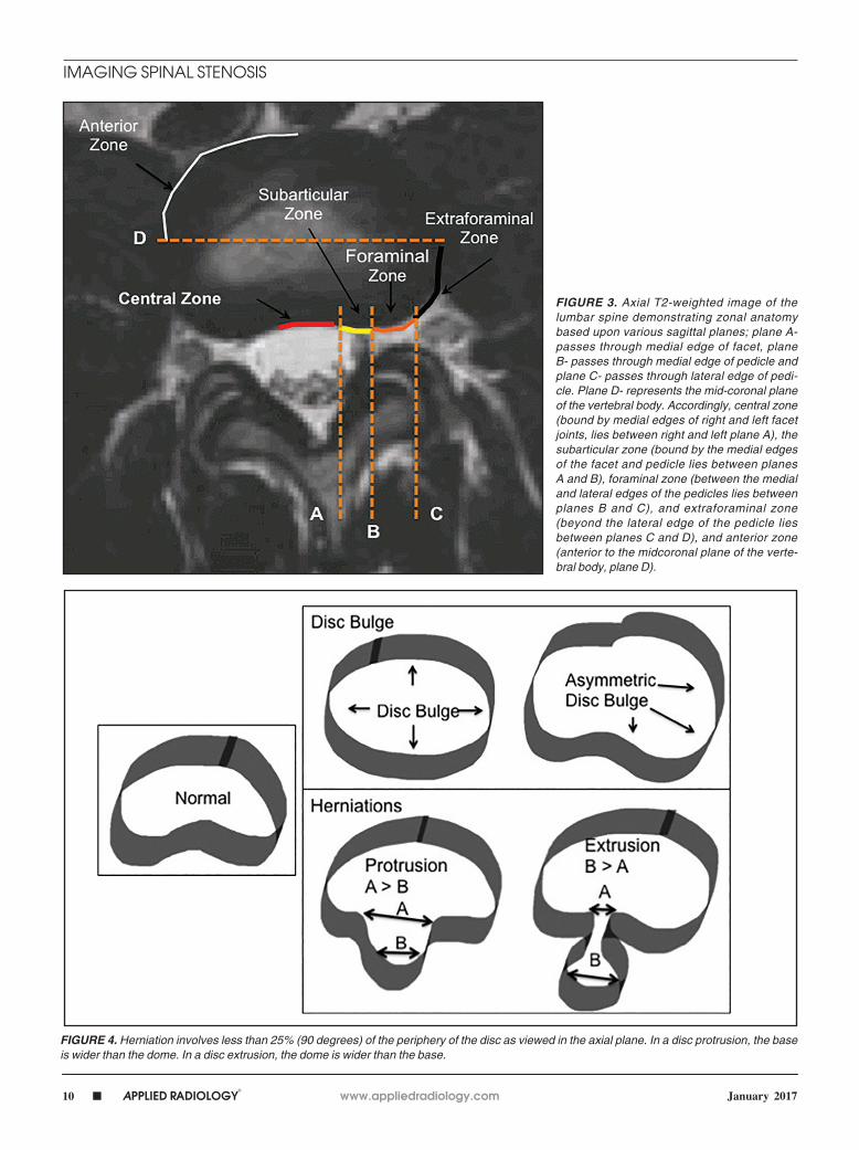
The purpose of the most recent ver-sion of the recommendations of com-bined task force comprised of North American Spine Society (NASS), American Society for Spine Radiology (ASSR), and the American Society of Neuroradiology (ASNR) is to improve communication between radiologists and clinicians. The nomenclature clearly defines anatomy in terms of zones and levels in order to standardize localization of pathology. In the sagittal plane, the pedicle serves as a boundary to describe levels with the different lev-els being disc level, suprapedicle level, pedicle level and infrapedicle level (Figures 1 and 2). Zones (central, sub-articular, foraminal, extraforaminal and anterior zones) are defined in the axial plane and are illustrated and described in Figure 3.
The nomenclature also defines the differences between disc herniation and disc bulge (Figure 4). Disc herniation is a broad term that encompasses the vari-ous manifestations of degenerative disc disease with extension of disc material beyond the edges of the vertebral body endplates; contrary to disc bulge, herni-ation is a focal extension involving less than 25% of disc circumference. Disc bulge is more diffuse (involving more than 25% of disc circumference) and rep-resents mild (3mm or less), extension of the disc material beyond the disc space; bulge may be symmetric or asymmetric.
Disc herniation may be further clas-sified into protrusion or extrusion. In protrusion, the greatest diameter of the herniated disc is less than its base at the site of herniation from the parent disc; extrusion describes a herniated disc, which has a maximum diameter greater than its base. A further sub-classifica-tion of disc extrusion is a sequestrated disc. Sequestrated discs are herniated discs that have no visible connection to the parent disc on any imaging plane. An overlooked or misdiagnosed seques-trated disc that migrates away from the parent disc level is a known cause of failed back surgery.9
FIGURE 1. Sagittal T2-weighted image of the lumbar spine demonstrates the supra-pedicu-lar, pedicular, infrapedicular and disc levels and their relationship to the disc and pedicle.
FIGURE 2. Axial CT images at the suprapedicular (A), pedicular (B), infra-pedicular (C), and disc levels (D).
A
C
B
D
10 n APPLIED RADIOLOGY©
www.appliedradiology.com January 2017
IMAGING SPINAL STENOSIS
FIGURE 3. Axial T2-weighted image of the lumbar spine demonstrating zonal anatomy based upon various sagittal planes; plane A- passes through medial edge of facet, plane B- passes through medial edge of pedicle and plane C- passes through lateral edge of pedi-cle. Plane D- represents the mid-coronal plane of the vertebral body. Accordingly, central zone (bound by medial edges of right and left facet joints, lies between right and left plane A), the subarticular zone (bound by the medial edges of the facet and pedicle lies between planes A and B), foraminal zone (between the medial and lateral edges of the pedicles lies between planes B and C), and extraforaminal zone (beyond the lateral edge of the pedicle lies between planes C and D), and anterior zone (anterior to the midcoronal plane of the verte-bral body, plane D).
FIGURE 4. Herniation involves less than 25% (90 degrees) of the periphery of the disc as viewed in the axial plane. In a disc protrusion, the base is wider than the dome. In a disc extrusion, the dome is wider than the base.
www.appliedradiology.com APPLIED RADIOLOGY©
n 11January 2017
IMAGING SPINAL STENOSIS
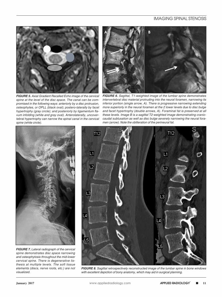
FIGURE 5. Axial Gradient Recalled Echo image of the cervical spine at the level of the disc space. The canal can be com-promised in the following ways: anteriorly by a disc protrusion, osteophytes, or OPLL (black oval); postero-laterally by facet hypertrophy (gray circle); and posteriorly by ligamentum fla-vum infolding (white and gray oval). Anterolaterally, uncover-tebral hypertrophy can narrow the spinal canal in the cervical spine (white circle).
FIGURE 6. Sagittal, T1-weighted image of the lumbar spine demonstrates intervertebral disc material protruding into the neural foramen, narrowing its inferior portion (single arrow, A). There is progressive narrowing extending more superiorly in the neural foramen at the 2 lower levels due to disc bulge and facet hypertrophy (double arrows, A). Foraminal fat is preserved at all these levels. Image B is a sagittal T2-weighted image demonstrating cranio-caudal subluxation as well as disc bulge severely narrowing the neural fora-men (arrow). Note the obliteration of the perineural fat.
FIGURE 7. Lateral radiograph of the cervical spine demonstrates disc space narrowing and osteophytosis throughout the mid-lower cervical spine. There is degenerative lis-thesis at multiple levels. The soft tissue elements (discs, nerve roots, etc.) are not visualized.
FIGURE 8. Sagittal retrospectively reconstructed image of the lumbar spine in bone windows with excellent depiction of bony anatomy, which may aid in surgical planning.
A B
12 n APPLIED RADIOLOGY©
www.appliedradiology.com January 2017
IMAGING SPINAL STENOSIS
It is important to carefully evaluate both, the zones (central, subarticular, foraminal, and extraforaminal) and lev-els (disc, supra-pedicular, pedicular, infra-pedicular) when assessing degen-erative disease. Disc herniations, bony hypertrophy, and ligamentous changes can compromise the spinal canal and cause stenosis in predictable locations (Figure 5). Foraminal stenosis can occur in the anteroposterior or craniocaudal direction as a result of disc herniation, facet hypertrophy or anteroposterior subluxation; the latter resulting from craniocaudal subluxation (Figure 6). In the lumbar spine, the inferior portion of the neural foramen narrows initially. Narrowing of the nerve-bearing, upper portion of the foramen is a late finding.
Indications for imaging stenosisTypical clinical features of stenosis
include buttock or lower extremity pain with a positive straight leg raise test, radiculopathy or neurogenic claudica-tion. Neurogenic claudication has been variably defined by radiculopathy or pain in the lower extremity that worsens with walking and improves with sitting or bending forward.1,10 The presence of these clinical findings suggests disc her-niation and/or stenosis. Uncomplicated acute low back pain or radiculopathy is
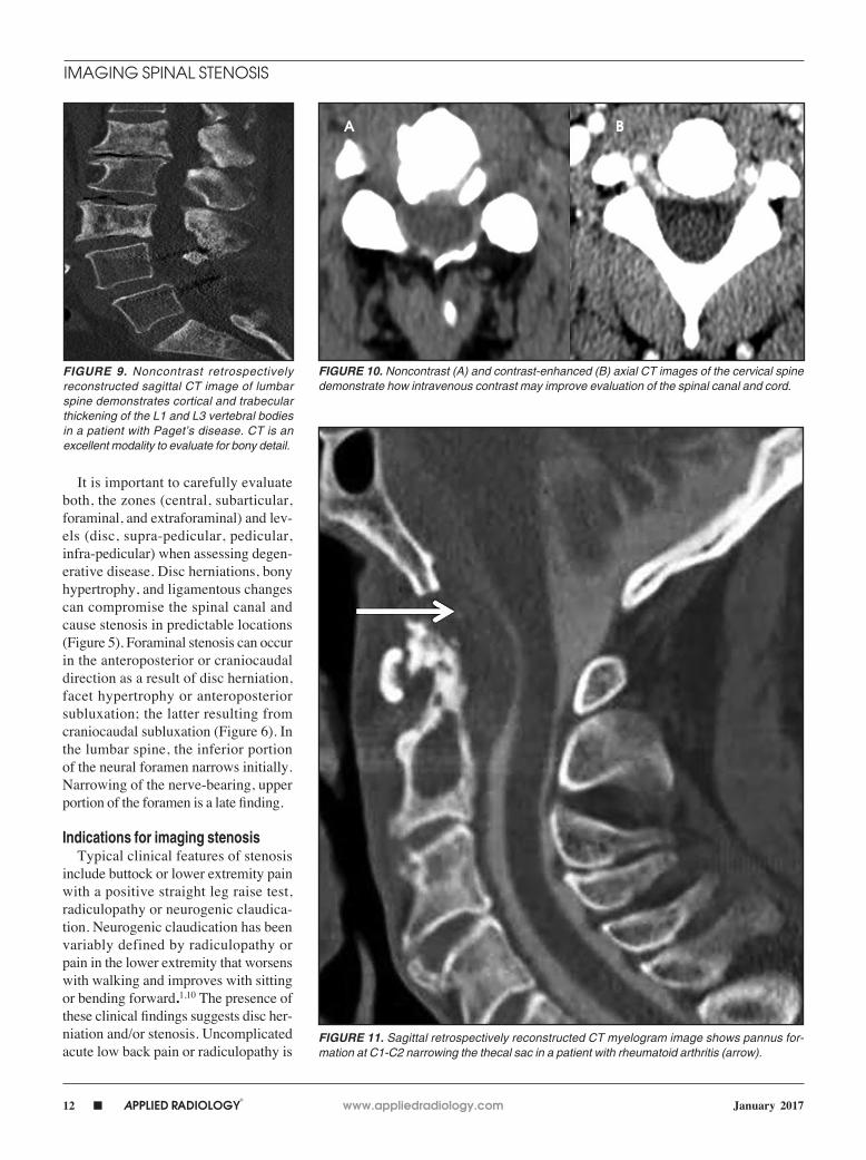
FIGURE 9. Noncontrast retrospectively reconstructed sagittal CT image of lumbar spine demonstrates cortical and trabecular thickening of the L1 and L3 vertebral bodies in a patient with Paget’s disease. CT is an excellent modality to evaluate for bony detail.
FIGURE 10. Noncontrast (A) and contrast-enhanced (B) axial CT images of the cervical spine demonstrate how intravenous contrast may improve evaluation of the spinal canal and cord.
FIGURE 11. Sagittal retrospectively reconstructed CT myelogram image shows pannus for-mation at C1-C2 narrowing the thecal sac in a patient with rheumatoid arthritis (arrow).
A B
www.appliedradiology.com APPLIED RADIOLOGY©
n 13January 2017
IMAGING SPINAL STENOSIS
a benign, self-limited condition that does not warrant any imaging studies. Imag-ing is considered in those patients who have had 4 to 6 weeks of medical man-agement and physical therapy that re-sulted in little or no improvement in their back pain. Imaging may be considered earlier if there is a history of malignancy, concern for infection, a fracture, symp-toms of true myelopathy (progressive or severe neurologic deficits), in the setting of cauda equina syndrome (urinary re-tention, fecal incontinence, motor deficit at multiple levels, and saddle anesthesia), or with history of back surgery.11,12,13 Degenerative changes are more common with increasing age. As these findings may be seen in both symptomatic and asymptomatic individuals, it is important that imaging findings be correlated with the physical exam.
Imaging modalities in stenosis Radiographs
Radiographs are often the initial means of evaluating back pain. Radio-graphs are low cost, readily available,
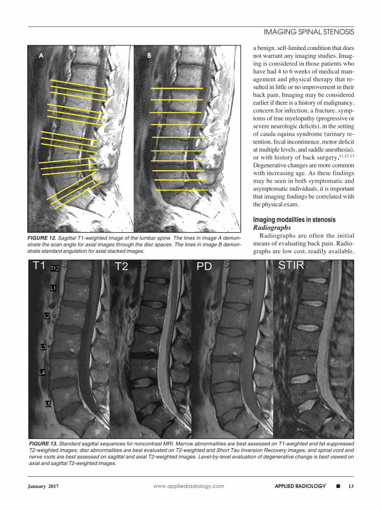
FIGURE 12. Sagittal T1-weighted image of the lumbar spine. The lines in image A demon-strate the scan angle for axial images through the disc spaces. The lines in image B demon-strate standard angulation for axial stacked images.
FIGURE 13. Standard sagittal sequences for noncontrast MRI. Marrow abnormalities are best assessed on T1-weighted and fat-suppressed T2-weighted images; disc abnormalities are best evaluated on T2-weighted and Short Tau Inversion Recovery images; and spinal cord and nerve roots are best assessed on sagittal and axial T2-weighted images. Level-by-level evaluation of degenerative change is best viewed on axial and sagittal T2-weighted images.
A B

14 n APPLIED RADIOLOGY©
www.appliedradiology.com January 2017
IMAGING SPINAL STENOSIS
and can assess for degenerative changes of disc height loss, vacuum phenome-non, osteophytes, and vertebral align-ment (Figure 7). Unrelated causes of back pain, such as sacroiliac joint pa-thology, renal stones, or calcified an-eurysmal dilatation of the aorta may also be identified. Soft tissue, disc and
nerve evaluation are limited, and ra-diographs are insensitive for metasta-ses and infection.14
Computed tomographyComputed tomography is the best
modality to depict bony anatomy for pre-surgical planning. It can also diagnose
disc herniation and spinal stenosis and is superior to radiographs in detecting metastases and infection (Figures 8 and 9).1,14 Nerve-root impingement is not re-liably detected and has the added disad-vantage of radiation exposure. Although typically performed without contrast, contrast-enhanced CT has been shown to provide improved visualization of disc pathology by evaluating for mass effect on the epidural venous plexus. Epidural enhancement surrounding a herniated disc can assist in its detection (Figure 10).15
For patients unable to have an MRI or who have had an inconclusive MRI, CT myelogram can serve as an alternative. Although this is an invasive procedure, contrast in the subarachnoid space out-lines the neural structures and is compa-rable to MRI in detecting stenosis and neural impingement (Figure 11).1 CT myelogram is also useful in diagnosing CSF leak and nerve root avulsion.
Magnetic resonance imagingMagnetic resonance imaging is the
modality of choice to evaluate stenosis and disc pathology.1,14 MRI has many advantages: it is noninvasive, has no ionizing radiation, has high sensitiv-ity in diagnosing stenosis, has high soft tissue contrast, and it best depicts cord, nerve roots, and bone marrow abnor-malities.1,14 Standard MRI sequences in the lumbar spine may include sagittal T1-weighted, T2-weighted, STIR, and proton density-weighted, and axial T1- and T2-weighted sequences (Figures 12 and 13). In addition, contrast enhanced MRI may be necessary for indications such as infection, tumor, and post sur-gical evaluation. Note that T2-weighted GRE sequence, often used in cervical spine imaging, may overestimate steno-sis and should be correlated with other sequences. MR images can also be de-graded by susceptibility artifact from metallic hardware and may be contra-indicated in some patients. In patients with history and physical examination findings consistent with degenerative lumbar spinal stenosis, MRI is suggested as the most appropriate, noninvasive test
FIGURE 14. Lateral radiographs of the cervical spine demonstrating normal atlanto-axial alignment in neutral position with dislocation on flexion (arrow).
FIGURE 15. (A) Axial T2-weighted image of L4-L5, where there is a disc protrusion. Note that the base of the herniation is wider than the diameter of the dome of the herniated disc. (B) Sagit-tal T2-weighted image of a disc extrusion (dome of the disc herniation being wider than the base) at L5-S1 causing obliteration of the CSF space in the thecal sac and nerve root compression.
A B
www.appliedradiology.com APPLIED RADIOLOGY©
n 15January 2017
IMAGING SPINAL STENOSIS
to confirm the presence of anatomic nar-rowing of the spinal canal or nerve root impingement.1
Dynamic flexion-extension radio-graphs (Figure 14) and CT and MRI with load bearing may also be per-formed as a useful adjunct.1
Qualitative diagnostic criteriaThe qualitative imaging findings
in stenosis of the lumbar spine may be broadly classified into the specific
causes of anatomic narrowing and their effect on neural elements. While this discussion of stenosis centers on the lumbar spine, the principles may also be applied to the cervical and thoracic regions. The main causes of spinal canal and neuroforaminal narrowing in the lumbar spine include disc herni-ation, facet hypertrophy, and ligamen-tum flavum hypertrophy/infolding. Additional causes of stenosis related to degenerative disease include synovial
cysts, and ossification of the posterior longitudinal ligament.
Common causes of anatomic narrowing Disc herniation
As previously discussed, disc her-niations are an important cause or con-tributor to stenosis (Figure 15). Several interventional therapies focus on disc removal, and accurate, reproducible radiologic description is imperative for optimal surgical outcomes.
Facet and ligamentum flavum hypertrophy
Facet and ligamentum flavum hyper-trophy frequently co-exist. Facet hyper-trophy refers to bony overgrowth at the facet joints of the lumbar spine on a de-generative basis. The bony overgrowth may then result in narrowing of the lat-eral recess or neural foramen. Spinal canal compromise may also occur, when superimposed disc herniation and liga-mentum flavum hypertrophy are present.
Ligamentum flavum hypertrophy or infolding refers to abnormal thickening and buckling of the ligamentum flavum
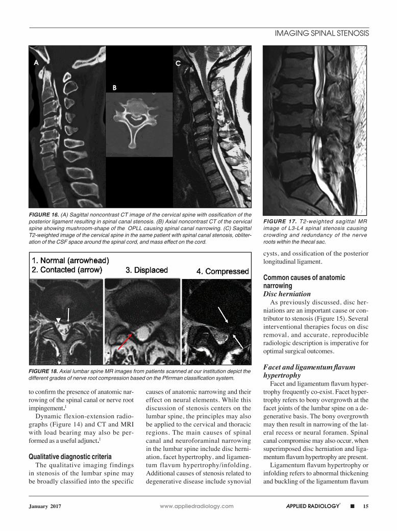
FIGURE 16. (A) Sagittal noncontrast CT image of the cervical spine with ossification of the posterior ligament resulting in spinal canal stenosis. (B) Axial noncontrast CT of the cervical spine showing mushroom-shape of the OPLL causing spinal canal narrowing. (C) Sagittal T2-weighted image of the cervical spine in the same patient with spinal canal stenosis, obliter-ation of the CSF space around the spinal cord, and mass effect on the cord.
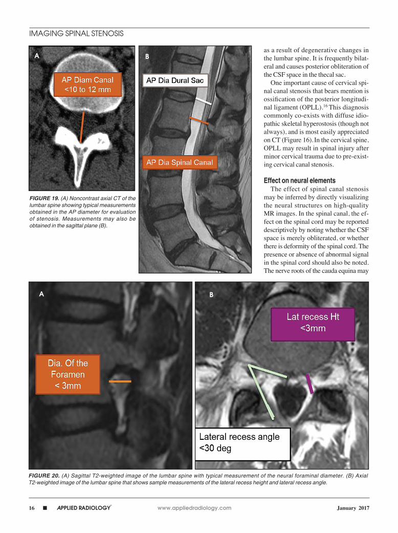
FIGURE 17. T2-weighted sagittal MR image of L3-L4 spinal stenosis causing crowding and redundancy of the nerve roots within the thecal sac.
FIGURE 18. Axial lumbar spine MR images from patients scanned at our institution depict the different grades of nerve root compression based on the Pfirrman classification system.
A
B
C
16 n APPLIED RADIOLOGY©
www.appliedradiology.com January 2017
IMAGING SPINAL STENOSIS
as a result of degenerative changes in the lumbar spine. It is frequently bilat-eral and causes posterior obliteration of the CSF space in the thecal sac.
One important cause of cervical spi-nal canal stenosis that bears mention is ossification of the posterior longitudi-nal ligament (OPLL).16 This diagnosis commonly co-exists with diffuse idio-pathic skeletal hyperostosis (though not always), and is most easily appreciated on CT (Figure 16). In the cervical spine, OPLL may result in spinal injury after minor cervical trauma due to pre-exist-ing cervical canal stenosis.
Effect on neural elementsThe effect of spinal canal stenosis
may be inferred by directly visualizing the neural structures on high-quality MR images. In the spinal canal, the ef-fect on the spinal cord may be reported descriptively by noting whether the CSF space is merely obliterated, or whether there is deformity of the spinal cord. The presence or absence of abnormal signal in the spinal cord should also be noted. The nerve roots of the cauda equina may
FIGURE 19. (A) Noncontrast axial CT of the lumbar spine showing typical measurements obtained in the AP diameter for evaluation of stenosis. Measurements may also be obtained in the sagittal plane (B).
FIGURE 20. (A) Sagittal T2-weighted image of the lumbar spine with typical measurement of the neural foraminal diameter. (B) Axial T2-weighted image of the lumbar spine that shows sample measurements of the lateral recess height and lateral recess angle.
A
A
B
B

www.appliedradiology.com APPLIED RADIOLOGY©
n 17January 2017
IMAGING SPINAL STENOSIS
also show crowding and redundancy above the site of narrowing (Figure 17). Pfirrmann et al proposed a grading sys-tem for disk herniation-related nerve root compromise that showed high correla-tion with intraoperative findings during subsequent lumbar spine surgery.17 In the Pfirrmann grading scheme, nerve root compromise is classified into four grades; normal, contact without dis-placement or compression, displace-ment, and compression, as shown in Figure 18. Grading of neural foraminal stenosis may be graded by noting efface-ment of the fat surrounding the nerve roots or by direct observation of nerve root displacement or compression with morphologic change.
Quantitative diagnostic criteriaIn 2011, Steurer and associates con-
ducted a review of quantitative radio-logic criteria published in the literature, and compiled a list of descriptive terms for lumbar stenosis.7 The quantitative diagnostic criteria for spinal canal ste-nosis are less widely accepted,8 and only the most relevant are discussed in this article. For the evaluation of the spinal canal, stenosis is compatible with an AP diameter of the canal less than 10 mm in the cervical spine or 12 mm in the lumbar spine (Figure 19). On MR images, a mid-sagittal diame-ter of the dural sac less than 10mm is also consistent with stenosis (Figure 19). Separate evaluation of the dural sac diameter is useful in cases where there is normal bony canal diameter on non-contrast CT images, for example epidural lipomatosis causes mass ef-fect on the dural sac with normal spinal canal diameters. Additional imaging criteria such as cross-sectional area of the dural sac and transverse diameter of the osseous spinal canal are also pub-lished in the literature.7
For evaluation of the neuroforamen, an anteroposterior diameter of the fo-ramen of less than 3mm on sagittal im-ages is considered diagnostic for stenosis (Figure 20A). A lateral recess height less than 3mm or lateral recess angle less than 30 degrees is also further evidence of spinal stenosis (Figure 20B). 7
The joint forces in the revised lumbar spine nomenclature recommendations6 suggest that spinal canal stenosis can be graded as mild, moderate, or severe if the canal is narrowed by less than a third, one-third to two-thirds, or greater than two-thirds of the original diameter, re-spectively. A similar grading system can be employed for the neural foramen.
ConclusionsThe imaging evaluation of spinal ste-
nosis continues to evolve, with a move towards standardization and validation of diagnostic criteria. The combined task forces of the NASS, ASSR and ASNR is a primary driver of this movement to-wards standardization of lumbar steno-sis nomenclature, and they continue to advocate a simple, reproducible, easily understood scheme for the evaluation of spinal stenosis. While the inherent value of accurate, standardized reporting of spinal stenosis is well recognized, it is important to remember that clinical sig-nificance depends on correlation with clinical data and cannot be inferred from morphologic data alone.
RefeRences1. Kreiner DS, Shaffer WO, Baisden JL, et al. An evidence-based clinical guideline for diagnosis and treatment of degenerative lumbar spinal stenosis. Spine J. 2013; 13(7):734-743.2. Deyo R, Gary D, Keurter W, et al. United States trends in lumbar fusion surgery for degenerative con-ditions. Spine. 2005;30(12):1441-1445.3. Brinjiki W, Luetmer P, Comstock B, et al. Sys-tematic literature review of imaging features of spinal degeneration in asymptomatic popula-tions. AJNR American Journal of Neuroradiology. 2015;36(4):811-816.
4. Brant-Zawadski M, Jensen M, Obuchowski N, et al. Imaging corner: spinal nomenclature. Inter- and intra-observer variability in interpretation of lumbar disc abnormalities: a comparison of two nomencla-tures. Spine. 1995;20(11):388-390.5. Fardon DF, Milette PC. Nomenclature and classi-fication of lumbar disc pathology: recommendations of the combined task forces of the North American Spine Society, American Society of Spine Radiol-ogy and American Society of Neuroradiology. Spine (Phila Pa 1976) 2001; 26: E93–113. 6. Fardon D, Williams A, Dohring E, et al. Lumbar disc nomenclature: version 2.0 recommendations of the combined task forces of the North Ameri-can Spine Society, the American Society of Spine Radiology and the American Society of Neuroradiol-ogy. Spine J. 2014;14(11):2525-25457. Steurer J, Roner S, Gnannt R, et al. Quantitative radiologic criteria for the diagnosis of lumbar spinal stenosis: a systematic literature review. BMC Mus-culoskelet Disord. 2011;12(1):175-183.8. Mamisch N, Brumann M, Hodler J, et al. Radiologic criteria for the diagnosis of spinal ste-nosis: results of a Delphi survey. Radiology. 2012;264(1):174-179.9. Choi K, Lee J, Kim J, et al. Unsuccessful percuta-neous endoscopic lumbar discectomy: a single-cen-ter experience of 10,228 cases. Neurosurgery. 2015;76(4):372-380.10. Genevay S, Atlas SJ, Katz JN. Variation in eligi-bility criteria from studies of radiculopathy due to a herniated disc and of neurogenic claudication due to lumbar spinal stenosis: a structured literature review. Spine. 2010; 35(7):803-811.11. Patel ND, Broderick DF, Burns J, et al. American College of Radiology ACR Appropriateness Crite-ria® Low Back Pain. Available at https://acsearch.acr.org/docs/69483/Narrative/ American College of Radiology. Accessed 12/12/2016.12. Chou R, Qaseem A, Owens DK, Shekelle P. Diagnostic imaging for low back pain: advice for high-value health care from the American College of Physicians. Ann Intern Med. 2011;154 (3):181–189. 13. Arana E, Kovac F, Royuela A., et al. Influence of nomenclature in the interpretation of lumbar disk countour on MR imaging: a comparison of the agreement using the combined task force and the Nordic nomenclatures. AJNR Am J Neuroradiol. 2011;32(6):1143-1148.14. Modic M, Masaryk T, Ross J, et al. Imaging of degenerative disc disease. Radiology. 1988; 168(1):177–186.15. Russell D, D’Angelo C, Zimmerman R, et al. Cer-vical disc hernation: CT demonstration after contrast enhancement. Radiology. 1984; 152(3): 703-712.16. Shoichiro O, Michimasa M, et al. Ossification of posterior longitudinal ligament: MR evaluation. AJNR Am J Neuroradiol. 1992; 13:1059 – 1067.17. Pfirrmann C, Dora C, Schmid M, et al. MR image-based grading of lumbar nerve root compromise due to disk herniation: reliability study with surgical cor-relation. Radiology. 2004;230(2):583-588.

![Spinal Stenosis [Autosaved]powerpoints007.s3.amazonaws.com/Spinal Stenosis [Autosaved].pdf · Causes of Spinal Stenosis: Chiropractic Care can: •arthritis -Reverse Arthritis •Herniated](https://img.pdfslide.us/doc/110x75/5edc014dad6a402d66667bdb/spinal-stenosis-autosavedpowerpoints007s3-stenosis-autosavedpdf-causes.jpg)