Embed Size (px)
Citation preview

Imaging Sensors Pointing and Tracking Controller Insensitiveto Inertial Sensors Misalignments
Hari B. Hablani∗
The Boeing Company, Huntington Beach, California 92647-2099
DOI: 10.2514/1.33014
This paper is concerned with a pointing controller for an imaging sensor mounted on a chaser satellite to track a
target satellite to rendezvous. Inertial attitude of the imaging sensor is estimated with gyros and star trackers and a
Kalman filter. It is shown that the pointing accuracy of the imaging sensor is independent of themisalignments of the
gyros and star tracker axes with the imaging sensor axes. This is important because the misalignments may be
uncalibrated or unknown. This paper presents the pointing controller, its analysis, and simulation results that
support the claim. Further, the results demonstrate that the controller meets the pointing accuracy requirement
under various misalignment conditions between the imaging sensor and the gyros and star trackers.
I. Introduction
T HIS paper is concerned with 1) the design of a pointing andtracking controller for an imaging sensor mounted on a chaser
satellite, aided by misaligned gyros and star trackers, and 2) theevaluation of the controller’s pointing accuracy while tracking aclient satellite for rendezvous.
The paper is organized as follows. Section II presents the imagingsensor pointing and tracking controller and analysis of its pointingaccuracy. Briefly, the pointing and tracking system comprises animaging sensor, misaligned gyros and a star tracker for inertialattitude estimation of the focal plane with a Kalman filter, anextended Kalman filter for inertial relative navigation of the targetsatellite, glide-slope guidance for rendezvous, pointing and ratecommands for tracking a target satellite, and an attitude controller.No alignment Kalman filter is used to calibrate the gyros and the startracker. Therefore, when an attitude estimator receives measure-ments from the gyros and star tracker that are misaligned with thespacecraft axes or optic axes, the attitude estimation errors developnonzeromeans. Thesemean errors cause errors in relative navigationof the target satellite, which in turn cause errors in the attitude and ratecommands for pointing and tracking the target satellite. Transferfunctions are developed that relate focal plane image angles with theattitude and rate command estimation errors and attitude and rateestimation errors. A linear statistical analysis is applied to evaluatethe focal plane image angle caused by these estimation errors. Themeans of the attitude estimation errors and their variances areformulated in Sec. III. Expressions of steady-state pre- and postup-date mean attitude estimation errors with star tracker measurementsare developed, and how attitude estimation errors affect relativenavigation of the target satellite is shown. Section IV summarizesquaternion pointing commands and rate commands for tracking atarget satellite. Section V presents simulation results for arendezvous scenario that calls upon all of the above components ofpointing and tracking and glide-slope guidance. Attitude estimationerrors and line-of-sight (LOS) command estimation errors due to thegyros and star tracker misalignments are illustrated. It is then shownthat the attitude error signal inputted to the attitude controller isindependent of these misalignments, however, and apart from high-
frequency noise the attitude error signal is nearly the same as the focalplane image angle, as intuition might suggest. The focal planepointing accuracy is shown to be unaffected by the misalignments,and the pointing accuracy requirement is shown to be met just thesame whether gyros and star trackers are misaligned with the opticalbench or not. Section VI concludes the paper.
II. Pointing Error Analysis of an OpticalNavigation System
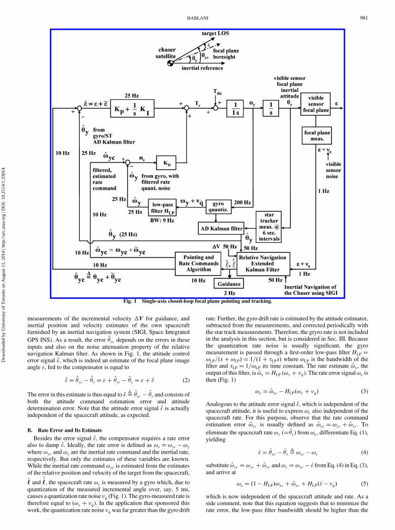
Figure 1 portrays a single-axis closed-loop control system forpointing an imaging sensor at a target satellite and tracking it. Anearly multi-axis version of this controller is presented in [1], but ourobjective here is to relate the focal plane angle of the target imagewith various error sources in the tracking system—a task analyzablemore clearly in a single-axis setup. Intuitively, because the aim of thecontrol system is to point the focal plane boresight at the target, it isthe focal plane image angle " that is to be nulled and is of centralimportance; the spacecraft attitude control enables this process, butthe spacecraft attitude and rate are quite possibly internal variablesand should not be involved in the evaluation of the pointing accuracy.This thought will be our guide in the following pointing analysis. Asingle-axis (spacecraft y-axis) dynamics is considered below.
A. Focal Plane Image Angle and Its Estimate
As the inset diagram inFig. 1 indicates, in the absence of any errorsor measurement noise, the focal plane angle " is related to the focalplane boresight attitude �y and the commanded pointing angle �yc,both measured from the same inertial reference, as
"� �yc � �y (1)
This equation or its equivalent form �yc � �y � " is validwhether theimage angle " has a zero mean or nonzero. Further, Eq. (1) revealsthat the usual attitude error signal (�yc � �y) fed to a compensatorwould be the same as the focal plane angle " if both �yc and �y wereknown.However, neither is known exactly; the angle �yc is estimatedfrom an estimate of the relative position of the target satellite from the
chaser satellite, denoted ‘, and the spacecraft attitude �y is measuredwith gyros and star trackers and is estimated with an attitudedetermination Kalman filter (Fig. 1). These angle estimates, denoted
�yc and �y, respectively, have estimation errors, usually denoted as~�yc and ~�y, defined by �yc � �yc � ~�yc, and �y � �y � ~�y. The
pointing command error ~�yc is due to the error in the relative position
estimate ‘ which, along with the relative velocity estimate _‘ neededto determine the rate command, is output of a relative navigationKalman filter [2]. As portrayed in Fig. 1, this Kalman filter uses focalplane measurements, inertial attitude estimates, accelerometer
Presented as Paper 2005-5982 at the AIAA Guidance, Navigation, andControl Conference, Austin, Texas, August 2005; received 22 June 2007;revision received 15 September 2007; accepted for publication 16 September2007. Copyright © 2007 by the American Institute of Aeronautics andAstronautics, Inc. All rights reserved. Copies of this paper may be made forpersonal or internal use, on condition that the copier pay the $10.00 per-copyfee to the Copyright Clearance Center, Inc., 222 Rosewood Drive, Danvers,MA 01923; include the code 0731-5090/08 $10.00 in correspondence withthe CCC.
∗Technical Fellow, Flight Sciences and Advanced Design. AssociateFellow AIAA.
JOURNAL OF GUIDANCE, CONTROL, AND DYNAMICS
Vol. 31, No. 4, July–August 2008
980
Dow
nloa
ded
by U
nive
rsity
of
Tor
onto
on
Aug
ust 1
1, 2
014
| http
://ar
c.ai
aa.o
rg |
DO
I: 1
0.25
14/1
.330
14
measurements of the incremental velocity �V for guidance, andinertial position and velocity estimates of the own spacecraftfurnished by an inertial navigation system (SIGI, Space Integrated
GPS INS). As a result, the error ~�yc depends on the errors in theseinputs and also on the noise attenuation property of the relativenavigation Kalman filter. As shown in Fig. 1, the attitude controlerror signal ", which is indeed an estimate of the focal plane imageangle ", fed to the compensator is equal to
"� �yc � �y � "� ~�yc � ~�y � "� ~" (2)
The error in this estimate is thus equal to ~"≜ ~�yc � ~�y and consists ofboth the attitude command estimation error and attitudedetermination error. Note that the attitude error signal " is actuallyindependent of the spacecraft attitude, as expected.
B. Rate Error and Its Estimate
Besides the error signal ", the compensator requires a rate erroralso to damp ". Ideally, the rate error is defined as !e � !yc � !ywhere !yc and !y are the inertial rate command and the inertial rate,respectively. But only the estimates of these variables are known.While the inertial rate command !yc is estimated from the estimatesof the relative position and velocity of the target from the spacecraft,
‘ and _‘, the spacecraft rate !y is measured by a gyro which, due toquantization of the measured incremental angle over, say, 5 ms,causes a quantization rate noise � _q (Fig. 1). The gyro-measured rate istherefore equal to (!y � � _q). In the application that sponsored thiswork, the quantization rate noise � _q was far greater than the gyro drift
rate. Further, the gyro drift rate is estimated by the attitude estimator,subtracted from the measurements, and corrected periodically withthe star track measurements. Therefore, the gryro rate is not includedin the analysis in this section, but is considered in Sec. III. Becausethe quantization rate noise is usually significant, the gyromeasurement is passed through a first-order low-pass filter HLP �!LP=�s� !LP� � 1=�1� �LPs� where !LP is the bandwidth of thefilter and �LP � 1=!LP its time constant. The rate estimate !y, theoutput of this filter, is !y �HLP (!y � � _q). The rate error signal!e isthen (Fig. 1)
!e � !yc �HLP�!y � � _q� (3)
Analogous to the attitude error signal ", which is independent of thespacecraft attitude, it is useful to express !e also independent of thespacecraft rate. For this purpose, observe that the rate commandestimation error ~!yc is usually defined as !yc � !yc � ~!yc. To
eliminate the spacecraft rate !y (� _�y) from !e, differentiate Eq. (1),yielding
_"� _�yc � _�y ≜ !yc � !y (4)
substitute !yc � !yc � ~!yc and!y � !yc � _" fromEq. (4) in Eq. (3),and arrive at
!e � �1 �HLP�!yc � ~!yc �HLP� _"� � _q� (5)
which is now independent of the spacecraft attitude and rate. As aside comment, note that this equation suggests that to minimize therate error, the low-pass filter bandwidth should be higher than the
Fig. 1 Single-axis closed-loop focal plane pointing and tracking.
HABLANI 981
Dow
nloa
ded
by U
nive
rsity
of
Tor
onto
on
Aug
ust 1
1, 2
014
| http
://ar
c.ai
aa.o
rg |
DO
I: 1
0.25
14/1
.330
14

bandwidth of the rate command !yc, the rate command estimationerror ~!yc should be small, and the low-pass filter bandwidth shouldbe no higher than necessary so as to minimize its response to thewideband quantization rate noise � _q.
C. Transfer Function of the Focal Plane Image Angle
Todetermine pointing accuracy "of the controller, that is, the focalplane image angle, it is now related with the pointing commands,disturbance acceleration �d�t�, and various error sources introducedabove. In particular, we derive the following transfer functionbetween "�s� and the variables just mentioned
"�s� � 1
p0�s�
��yc �
1
s2!yc�1 �HLP�ad
�� 1
s2p0�s��d�s�
� 1
s2p0�s�
�~"
�ap �
1
saI
�� � ~!yc � HLP� _q�ad
�(6)
where the polynomial p0�s� is
p0�s� � 1
s3�s3 �HLPads
2 � aps� aI � (7)
and the proportional, integral, and derivative (PID) gains are definedas ap � Kp=I, ad � KD=I, and aI � KI=I, with I as the moment ofinertia of the spacecraft about the axis in consideration; �d is thedisturbance acceleration. In deriving the above transfer function, thefocal plane image rate _" is expressed as s " (s), �y is substituted in
terms of " and �yc, and likewise the rate _�y � !y is replaced in termsof _" and!yc. The numerator of the polynomialp0�s� above appears ascubic, but becauseHLP is afirst-orderfilter, thep
0�s�becomes quarticon simplification. However, because the bandwidth of HLP must bemuch higher than the bandwidth of the PID controller, HLP � 1within the controller bandwidth and the numerator of p0�s� isessentially cubic. Also, inasmuch as the PID controller bandwidth isintended to be much higher than the bandwidths of the pointingcommand �yc, rate command !yc, and disturbance acceleration �d,most of the pointing error is caused by the pointing command and
rate command estimation errors ~�yc and ~!yc, and the attitude and rate
determination errors ~�y and � _q. As such, we will focus on these errorsources next.
Recall that the estimation error ~" in Eq. (6) equals ~�yc � ~�y. The
error ~�yc arises from the relative position estimation error ~‘. One of
the sources of ~‘ is the attitude estimation error ~�y because �y is fed to
the relative navigation extended Kalman filter (Fig. 1). If the error ~�yhas a nonzero mean due to the gyro and star tracker misalignments,this mean error (time varying as we shall see in Sec. III) will misalign
the inertial frame in which ‘ and _‘ are estimated, and then manifest
itself in ~�yc. A statistical analysis of attitude estimation error due tothe misalignment angles is developed in Sec. III. Meanwhile we notethat the misalignment angles apparently null themselves from
~�yc � ~�y. There may still be some bias error in the estimates ‘ and _‘due to other sources of errors in the inputs to the relative navigationfilter—inertial navigation, for instance, or due to the filter’s inherent
linear approximation. Denote the mean error signal as �~"� �~�yc ��~�y,
where ( �~� ) is the mean of the estimation error ( ~� ). One can show withthe aid of the final value theorem that, due to the integral gain in the
attitude controller, the steady-state pointing accuracy " is "� �~".
D. Standard Deviation of the Focal Plane Image Angle
We will first determine the image angle " due to the zero-meanrandom error component in ~" caused by the attitude estimation error~�y. The variance of ~�y depends on the gyro and star tracker randomerrors and star tracker measurement update interval, as analyzed in
[2,3]. The zero-mean random error in ~" due to ~�yc may be significantalso due to the errors in the inertial navigation of the chaser satellite,depending on the noise attenuation properties [4] of the relativenavigation extended Kalman filter. However, regarding the image
angle " due to ~�y, note the following transfer function between " and
the estimation error ~�y�s� from Eq. (6):
"�s� � 1
s2p0�s� �ap � aI=s�~�y�s� (8)
which agrees with Eq. (3) of [5]. Denoting the standard deviation(s.d.) of the attitude estimation error as � ~�, we note that, in steadystate, it is maximum before the star tracker measurement update andminimum after the update [3]. Assuming that the maximum valueprevails all the time, standard deviation �" of the pointing accuracy "in Eq. (8) due to � ~� with the PID attitude controller operating at asampling frequency fs will be, by applying the linear statisticalanalysis [6,7],
�2" ��2~�2fs
a2p � adaIadap � aI
(9)
assuming that HLP � 1 in the characteristic equation (7).Regarding the rate error ~!yc �HLP� _q in Eq. (6), we again assume
that the rate command estimation error ~!yc is not significantcompared to the filtered rate quantization noiseHLP� _q and thereforewe focus on the image angle " caused by this rate noise only. NotethatHLP cannot be treated as unity now because the purpose ofHLP isto attenuate � _q noise. For statistical error analysis, variance of the ratequantization noise is required. Franklin et al. in [8] shows that if thespacecraft attitude �y is quantized with q rad per pulse, thequantization error can be approximated then as a band-limited white
noise with the standard deviation �q � q=������12p
. If fs is the outputsample frequency of the gyro (200 Hz in Fig. 1), then the flatspectrum of the quantization error is limited to�0:5fs f 0:5fs,and standard deviation � _q of the rate noise is [9] � _q �
���2p�q=�s,
where �s is the sample period of the gyro output, equal to 1=fs. Thecorresponding power spectral density of the band-limited rate noise� _q is V _q � �2_q=fs. Variance of the pointing error is then found to be
[6,7]
�2" �a1b2
�a0a23 � a21a4 � a1a2a3�
��2_q2fs
�(10)
where a0; . . . ; a4 are coefficients of the quartic characteristicpolynomial; these and b2 are defined as
a0 � 1 a1 � !LP a2 � !LPad � apa3 � !LPap � aI a4 � !LPaI b2 ��!2
LPa2d
(11)
For details of deviation of Eq. (10), see [2]. Standard deviation of theimage angle due to quantization rate noise is thus given by �" fromEq. (10). The variance results Eqs. (9) and (10) will be illustrated inSec. V.
III. Attitude Determination with Misaligned Gyrosand Star Trackers
Our objective in this section is to determine the steady-state bias
and variance of the attitude estimation error ~�y when the attitudeestimator employs measurements from the misaligned gyros and startrackers.
In practice, gyros, star trackers, and imaging sensors are somewhatmisaligned from their ideal orientation due to installationimprecision, launch impacts, and time-varying thermal gradients inorbit. These misalignments can be estimated with an alignmentKalman filter [10], but in its absence, it is not clear how the attitude
estimation error ~�y and the image angle " are affected by themisaligned, uncalibrated gyros and star trackers. One suspects in this
circumstance the inertial attitude estimate �y would be relative to amisaligned inertial frame instead of the true inertial frame, and
therefore the estimated pointing commands �yc would be relative tothis misaligned inertial frame also, provided there are no other
982 HABLANI
Dow
nloa
ded
by U
nive
rsity
of
Tor
onto
on
Aug
ust 1
1, 2
014
| http
://ar
c.ai
aa.o
rg |
DO
I: 1
0.25
14/1
.330
14

relative position estimation error sources. As a result, the focal plane
image angle estimate, that is, the control error signal "� �yc � �y inFig. 1,would be, intuitively, independent of the gyros and star trackermisalignments. Our objective in this paper is to validate thisintuition. The uncalibrated imaging sensor’s ownmisalignment withthe optical bench or spacecraft frame will, of course, cause a biaserror in pointing that one will be able to estimate from the innovationusing an adaptive relative navigation Kalman filter [9,11] but wewillnot pursue this topic here.
A. State-Space Model of Attitude Estimation with Misaligned Gyros
Following [10] and considering a single-axis again, the yb axis ofthe spacecraft, the y gyro is assumed to be misaligned by a smallangle �yx in the xbyb plane and a small angle �yz in the ybzb plane.Then the rate input to the y gyro is
!y;input � !y � �yx!x � �yz!z (12)
where!� �!x;!y;!z� is the spacecraft angular rate in the spacecraftframe. We will now develop a recursive model of the attitudemeasurement process of this gyro after Markley and Reynolds [3]. Agyro measures the spacecraft attitude at a very high samplingfrequency (200 Hz in Fig. 1). The (k� 1)th sample of the spacecrafty attitude is given in terms of the kth sample by
�y;k�1 � �y;k ���y;k�1 (13)
where��y;k�1 is the true incremental change in the y attitude in onesample period, to be measured by the y gyro. Recalling Eq. (12), the(k� 1)th angle actually measured by the misaligned gyro beforequantization is
�y;k�1 � �y;k � �bk � �k ���y;k�1 � �yx��x;k�1 � �yz��z;k�1(14)
where � � the sample period of this recursive process, bk � thegyro drift rate, �k � the incremental randomwalk plus an angle dueto the drift acceleration, and��x;k�1 and��z;k�1 are the incrementalspacecraft attitude angles about the spacecraft x axis and z axis due tothe orthogonal rates!x and!z. The gyromeasures the last three termsin Eq. (14) as one quantity. Because of quantization, the gyro outputangle will be
�y;k�1;meas � �y;k�1 � �q;k (15)
where �q;k is the quantization error.Because the mean and variance analysis of the attitude
estimation error must be independent of the spacecraft attitudedynamics, the true incremental angle ��y;k�1 is determined interms of the quantized gyro measurements �y;k�1;meas bysubstituting �y;k�1 from Eq. (14) in the right side of Eq. (15),expressing ��y;k�1 in terms of other quantities, and thensubstituting ��y;k�1 in Eq. (13). We then obtain the followingrecursive equations that do not involve ��y:
�y;k�1 � �y;k � �y;k�1;meas � �y;k � �bk � �k � �k�1 � �q;k (16a)
�y;k�1 � �y;k�1;meas � �q;k (16b)
bk�1 � bk � �k (16c)
where a gyro measurement is now an input; the third equationabove models the change in the drift rate with �k as an increment,and the error angle �k�1 abbreviates the last two terms in Eq. (14)
�k�1 ���yx��x;k�1 � �yz��z;k�1 (17)
For further analysis, Eqs. (16) are written in the state-space form as
�y;k�1
bk�1
�y;k�1
264
375�
1 �� �10 1 0
0 0 0
264
375
�y;k
bk
�y;k
264
375�
1
0
1
264
375�y;k�1;meas
���k � vq;k
�k
�vq;k
264
375 �
�k�1
0
0
264
375 (18)
or, in compact notations, it is written as
x k�1 ��xk � � 1 0 1 �T�y;k�1;meas �wk ��k�1 (19)
where the definition of each symbol in Eq. (19) is apparent bycorrespondence with Eq. (18).
The attitude estimation model for the y axis used in the attitudeestimator is unaware of the gyro misalignments and the angle input�k�1 from orthogonal axes. Also, the mean of the noise vectorwk inEq. (29) is zero. Hence, the attitude estimation model is
x k�1 ��xk � � 1 0 1 �T�y;k�1;meas (20)
where xk � ��y;k; bk; �y;k�.
B. Attitude Estimation Error
Define the state estimation error vector [9] ~xk � xk � xk, governedby an equation obtained by subtracting Eq. (19) from Eq. (20)
~x k�1 ��~xk � wk ��k�1 (21)
Equation (21) is somewhat equivalent to the single-axis version ofthe three-axis Eq. (34) of [10]. Because of misalignment angles, ~xk isnot a zero-mean vector. Indeed, taking the mean of Eq. (21), wearrive at
�~x k�1 ���~xk ��k�1 (22)
where �~x is the mean of ~x.To determine variance of the estimation error, define the zero-
mean random error in ~x as [9] ~~xk � ~xk � �~xk. Then the equation
governing ~~xk is obtained by subtracting Eq. (22) from Eq. (21)
~~x k ��~~xk�1 � wk�1 (23)
The corresponding 3 3 covariance matrix propagation equation is
Pk ��Pk�1�T �Q, as always, where the covariance matrix Pk �
E�~~xk ~~xTk � and the process noisematrixQ is as defined in [3], involving
�2u � the power spectral density (rad2=s3) of the continuous-timeacceleration of the drift, �2v � the power spectral density (rad2=s) ofthe continuous-time random walk rate, and �2q��q2=12� is thediscrete-time variance of the quantization error. Interestingly, theabove mean and variance approach is different from the approach in[10] wherein one would use Eq. (21) directly for estimation andconstruct a cover covariance matrix of the spacecraft’s rates andmisalignment angles.
Because of a random walk, the variance of the spacecraft attitudeestimate grows without bounds. To limit this variance, star trackermeasurements are used, but a star trackermay also bemisaligned.Weconsider this update process next.
C. Attitude Estimate and Variance Update with Misaligned Star
Trackers
The spacecraft attitude measurement with star trackers may takeplace periodically, with a period T. Although not a requirement, herewe assume thatT is amultiple of the preceding sample period � of thegyro attitude measurement process. In particular, following [3], weassume that when k� n, T � n�, a star tracker measures instantlythe spacecraft attitude and furnishes
HABLANI 983
Dow
nloa
ded
by U
nive
rsity
of
Tor
onto
on
Aug
ust 1
1, 2
014
| http
://ar
c.ai
aa.o
rg |
DO
I: 1
0.25
14/1
.330
14

zst � �y;n � �st;y � �st (24)
where �y;n is the true spacecraft attitude about the inertial y axis whenk� n; �st;y is an unknown bias error in the star tracker measurementdue to its misalignments, and �st is a zero-mean white noise withvariance �2st contaminating the star tracker measurements. The gyro
estimate of the spacecraft attitude �y;n��� at t� n� just before thestar tracker measurement is obtained from the state vector estimatexn���, Eq. (20). The vector xn��� is updated to xn��� with the startracker measurement zst, thus
x n��� � xn��� �Kss�zst � �y;n���� (25)
where Kss is the (3 1) Kalman gain vector of the steady-stateattitude determination Kalman filter; see [1,3] for steady-state valuesof the Kalman gains.
To evaluate the mean and the variance of the state vectorestimation error after the star tracker measurement update and topropagate them further with gyro measurements, we substitute thestar tracker measurement zst, Eq. (24), in Eq. (25), define the
preupdate spacecraft attitude estimation error ~�y;n��� �� �y;n��� ��y;n that emerges in the innovation, and subtract the true state vectorxn from both sides of the equation. We then arrive at the stateestimation error update equation
~x n��� � ~xn��� �Kss��st;y � �st � ~�y;n���� (26)
The mean of this state vector estimation error update equation is
�~x n��� � �~xn��� �Kss��st;y ��~�y;n���� (27)
To update the variance of ~xn, the mean �~xn��� is subtracted from
~xn���. Recalling the definition ~~xk � ~xk � �~xk, we arrive at thefollowing update equation of the zero-mean estimation error vector~~xn:
~~x n��� � ~~xn��� �Kss��st �~~�y;n���� (28)
where the zero-mean estimation error~~�y;n��� is defined as
~~�y;n��� � ~�y;n ��~�y;n. Postmultiply Eq. (28) with its own transpose
and perform its expectation operation. The following covarianceupdate equation then follows:
Pn��� � Pn��� � Pn;1���KTss � KssPTn;1���
�KssKTss�Pn;11��� � Rst� (29)
where
P n;1����Eh~~xn���~~�y;n���i� the first column of Pn��� (30a)
P n;11��� � Eh~~�2
y;n���i � �1; 1� element of Pn��� (30b)
andRst is the variance of the star tracker measurement noise �st. Notethat the above update process maintains symmetry of the covariancematrix Pn because Eq. (29) is of a Joseph form. After the aboveupdate, the gyro measurement process continues recursively for thenext k� 0; 1; . . . ; n samples with the sample period �, and the startracker measurement and update recurs at t� T.
D. Steady-State Pre- and Postupdate Mean Attitude Estimation
Error
One can derive literal steady-state mean of the attitude estimationerror from the previous recursive attitude determination process.This steady-state process is portrayed in Fig. 2where the index k� nis reset to k� 0 at every star tracker measurement epoch. Ourobjective now is to determine the pre- and postupdate mean attitudeestimation error in terms of the gyro and star tracker misalignments.
In the state vector estimate xk, the first element is the spacecraft
attitude estimate �y;k. So the first row of Eq. (26) is
~� 0��� � ~�0��� � k���st � �st � ~�0���� (31)
where the subscript n is replaced with “0,” the subscript y is droppedfrom �y for clarity, and k� is the Kalman gain associated with �y. Thesteady-state Kalman gain k� is [3] k� � 1 � �2 where depends onthe standard deviations �u, �v, �q, and �st of the gyro and the startracker noises, gyro sample period �, and the star trackermeasurement update interval T. Therefore, Eq. (31) can be rewrittenas
~� 0��� � �2 ~�0��� � �1 � �2���st � �st� (32)
the mean of which would be
�~� 0��� � �2�~�0��� � �1 � �2��st (33)
Over the interval T from k� 0 to k� n, due to misalignment anglesof the y gyro and orthogonal rates of the spacecraft, the y gyroaccumulates an angular error of
�n ≜ ��yxZT
0
!x dt� �yzZT
0
!z dt�Xn�1k�0
�k�1 (34)
From t� 0 to t� n�, the attitude estimation error grows from ~�0���to
~� n��� � ~�0��� ��n � �b � b�T � �rw�T� � �q (35)
where b is the drift rate estimate, �rw (T) is the randomwalk at t� T,and �q is the quantization noise. Note that unlike the random walk,the quantization noise does not accumulate or grow. Because the
random quantities in Eq. (35) have zero mean, the mean of ~�n���would be
�~� n��� ��~�0��� ��n (36)
In steady state,�~�n��� �
�~�0���; therefore, Eqs. (33) and (36) can besolved for the unknown pre- and postupdate mean estimation errors,arriving at
preupdate :�~�0��� � �1 � �2��1�n � �st (37a)
postupdate :�~�0��� � �2 � 1��1�n � �st (37b)
each expressed exclusively in terms of the gyro/star trackermisalignment angles. Clearly, if themisalignment angles �yx, �yz, and�st;y were all zero, the above two means would be zero also.
The nonzero mean errors developed above cause relative positionand relative velocity estimation errors, which in turn cause pointingand rate command estimation errors, according to the signal pathshown in Fig. 1.
Fig. 2 Single-axis steady-state attitude determination Kalman filter:
pre- and postupdate mean attitude estimation errors with a misaligned
star tracker measurement.
984 HABLANI
Dow
nloa
ded
by U
nive
rsity
of
Tor
onto
on
Aug
ust 1
1, 2
014
| http
://ar
c.ai
aa.o
rg |
DO
I: 1
0.25
14/1
.330
14

E. Attitude Estimation Error Affecting Relative Navigation
Figure 3 illustrates how the star tracker misalignment affects thefocal plane measurement about the y axis. Suppose the focal planeboresight is oriented at an angle � from an inertial reference, and thetarget is located at an elevation angle " from the focal plane boresight.Then, the true inertial line-of-sight angle of the target is (�� "). Theangle � is measured by a star tracker which is misaligned about they axis by �st such that the measurement is �st � �� �st per Eq. (24)with zero random noise. Because the focal plane boresight attitude inthe inertial frame is �, the measurement �st is effectively from anestimated inertial reference at the misalignment angle �st from thetrue inertial reference, as shown in Fig. 3. The apparent inertial line-of-sight angle of the target is thus �st � "� �� �st � ".
A vector/matrix counterpart of the above scalar representationaffecting relative navigationwill be formulated now. Figure 4 depictsa sensor focal plane whose center is hypothetically at the mass centerof the chaser satellite. In the sensor frame xs ys zs, with the xs axis asthe sensor boresight, the focal plane azimuth and elevation line-of-sight (small) angles are �� tan�1�ys=xs�, and "� tan�1��zs=xs�,and the client satellite is located at the relative position ‘s ��xs; ys; zs�T in the sensor frame. In the inertial frame, the line-of-sightvector ‘ from the chaser satellite to the client satellite is related to ‘svia the inertial attitude direction cosine matrix CIs of the sensor
frame: ‘FI � CIs‘s whereFI denotes the inertial frame. For a relative
navigation Kalman filter, the state vector of which is in inertialCartesian coordinates [2], we require slopes of the angles � and "
with respect to the estimated LOS vector ‘. These slopes are relatedto the slopes in the sensor frame, thus [12]
@�
@‘� CIs
@�
@‘s; (38a)
@"
@‘� CIs
@"
@‘s(38b)
where CIs is the estimated inertial attitude of the sensor, and ‘ is theestimate of the relative position ‘s of the target in the sensor frame.
The attitude determination Kalman filter provides CIs. Because the
gyro/star tracker misalignment angles affect the estimate CIs, clearly
the relative position and relative velocity estimates, ‘ and _‘, of the
client from the chaser will be reckoned from the misaligned inertialframe, as in Fig. 3. As a side comment, we note that in our earlierwork, [1], the slopes of the angles � and " in the sensor frame inEqs. (38) were transformed to the local-vertical–local-horizontal(LVLH) orbit frame. But this frame is not adopted here because theClohessey–Wiltshire relative equations ofmotion in this frame causesignificant relative navigation errors at the 10–20-km range [13]where an imaging sensor begins to sense a target satellite.
IV. Pointing and Tracking Commands
When the relative position vector ‘ of the target satellite from thechaser satellite has been estimated with a relative navigation Kalmanfilter [2] or otherwise, it is used to calculate the pointing command tobring the target to the focal plane center. Suppose the focal planeboresight unit vector b is initially aligned with the inertial x axis ofthe frame inwhich ‘ is estimated; then [14] shows that the quaternioncommand to align the boresight b with ‘ is
qcI �1�������������������������
2�1� b � u�p �b u; 1� b � u� (39)
where u is the unit vector along ‘�u� ‘=j‘j�. Clearly, if there is
some estimation error in the estimate ‘wherefrom the unit vector u iscalculated, the estimated pointing command qcI will have someestimation error.
While the pointing command (39) is used to acquire and then trackthe target, the rate command may be used to track the target with
greater precision. Knowing the relative velocity vector _‘, the angularrate command to track the target is [1]
! cI � �‘ _‘�=�‘ � ‘� (40)
where the estimates of ‘ and _‘ are known in the inertial frame. Fromthe attitude control standpoint, the rate command !cI needs to beknown in the current body frame, however, so that the rate error!e �!cI � !bI can be calculated for control in this frame (where!bI � the spacecraft’s inertial rate in the body frame). Therefore ‘
and _‘ need to be transformed from the inertial frame to the currentbody frame and then substituted in Eq. (40).
V. Numerical Results and Discussion
A. Rendezvous Scenario Using Glide-Slope Guidance
To illustrate relative navigation and guidance for the rendezvousof one satellite with another using the imaging sensor pointingcontroller, Fig. 1, and to illustrate the controller’s insensitivity to thegyro and star tracker misalignments, we developed a 9-degree offreedom (DOF) simulation: three translation DOF of the clientsatellite, and six translation and rotational DOF of the chaser satellitein a spherical plus J2 gravity field. We consider a scenario shown inFig. 5 where the chaser satellite is�19 km behind and 10 km belowthe target satellite at t� 0. The initial position and velocity of the twosatellites were specified in the inertial frame using orbital elements.Because guidance improves the estimation process due to additionaldynamics and accelerometer measurements, a 1=60 Hz (i.e.,sampling period 60 s) glide-slope guidance [15] is employed. Thisguidance technique decreases relative velocity and positionexponentially. The global positioning system (GPS)-based inertialnavigation errors of the chaser satellite are simulated asexponentially correlated Markov processes with the followingparameters† representing a precise positioning service ofGPS [9,16]:
s.d. of bias in each axis� 5:1 m, time constant� 1=8 orbitalperiod;
s.d. of horizontal random error� 1:4 m, time constant� 1 min;s.d. of velocity random error � 0:07 m=s.In 1800 s, the guidance system steers the chaser satellite to its final
position ��1; 0; 1� km relative to the target in the target’s
Fig. 3 True inertial angles of the focal plane boresight and target, andmeasurement with a misaligned star tracker (ST).
Fig. 4 Sensormeasurements for relative navigation of the chaser: focal
plane at the vehicle center of mass and aligned perfectly.
†Courtesy of D. Childers, The Boeing Company, Huntington Beach,California.
HABLANI 985
Dow
nloa
ded
by U
nive
rsity
of
Tor
onto
on
Aug
ust 1
1, 2
014
| http
://ar
c.ai
aa.o
rg |
DO
I: 1
0.25
14/1
.330
14

instantaneous LVLH frame. Because the LVLH frames areconvenient to visualize the motion of the chaser satellite relative tothe target satellite, both true and estimated instantaneous LVLHframes of the two satellites are computed and used; the controlsystem is based on inertial angles and inertial rates, however. Therelative position and velocity estimates of the chaser satellite haveinitial estimation errors equal to �1; 0:49; 0:49� km (Fig. 5) and�0:5; 0:5; 0:5� m=s. A 10-Hz relative navigation Kalman filterremoves the large initial estimation errorwith thefirst few 1-Hz anglemeasurements by the imaging sensor. The details of this filter arepresented in [1,2]. To isolate the effects of the gyro and star trackermisalignments, gyro drift, random walk, quantization and star
tracker measurement noise are all ignored, although their variancesare considered to determine the steady-state Kalman gains of theattitude estimator for blending the misaligned gyro and star trackermeasurements. Only the imaging sensor random noise is included inthe simulation. The glide-slope guidance commences at t� 60 s,and steers the spacecraft to its final position in 29 pulses, one pulseevery 60 s, in the remaining 1740 s. This gliding motion on a slope(hence the name glide slope) in the target satellite orbit plane isdepicted in Fig. 5.
B. Pointing and Rate Commands
Although for attitude control the inertial quaternion com-mands (39) and the inertial rate command vector (40) are used in thesimulation, Euler angle commands and scalar rate commands arestated here for clarity and illustration. Assuming that the focal planeboresight is initially alignedwith the xI-inertial axis, and that the line-of-sight vector ‘ in the inertial frame is ‘F
I � �‘xI; ‘yI; ‘zI �, thepointing commands about the inertial yI axis and about the once-displaced zI axis are [15] �yI;c � arctan��‘zI; ‘xI�, and�zI;c � arcsin�‘yI=k‘k�, where k‘k � �‘2xI � ‘2yI � ‘2zI�1=2. For ratecommand, the line-of-sight vector ‘would be ‘F
c � �‘xc; 0; 0� in thecommanded body frame because the commanded focal planeboresight axis xc is pointed at the target. Expressing the line-of-sight
inertial velocity vector _‘ in the commanded body frame as_‘Fc � � _‘xc; _‘yc; _‘zc�, Eq. (40) yields these three components of the
rate command in the commanded body frame: !xc � 0,
!yc �� _‘zc=‘xc, and !zc � _‘yc=‘xc. The true and the estimatedpointing commands ��yI;c; �zI;c� and the rate commands �!yc; !zc� inthe presence of imaging sensor noise and GPS-based inertialnavigation errors are illustrated in Figs. 6a and 6b, respectively, for
Fig. 5 A six-state relative inertial navigation: inertial propagation for
relative navigation of target satellite.
0 500 1000 1500 2000-3
-2.5
-2
-1.5
-1
Time(s
Ele
vatio
n P
oint
ing
Com
man
d&
its
estim
ate
from
EC
I (r
ad)
0 500 1000 1500 2000-0.5
0
0.5
1
1.5
Time(s)
Azi
mut
h P
oint
ing
Com
man
d&
its
estim
ate
from
EC
I (r
ad)
0 500 1000 1500 2000-15
-10
-5
0
5x 10
-4
Time(s)Trac
king
Rat
e C
omm
ands
: ω yc
,ω yc
est
0 500 1000 1500 2000-1.5
-1
-0.5
0
0.5
1x 10
-3
Time(s)Trac
king
Rat
e C
omm
ands
: ω zc
,ω zc
est
(ra
d/s
)
guidance activated @ 60s
true
estimate
0 500 1000 1500 2000-3
-2.5
-2
-1.5
-1
Time(s)
Ele
vatio
n P
oint
ing
Com
man
d&
its
estim
ate
from
EC
I (r
ad)
0 500 1000 1500 2000-0.5
0
0.5
1
1.5
Time(s
Azi
mut
h P
oint
ing
Com
man
d&
its
estim
ate
from
EC
I (r
ad)
0 500 1000 1500 2000-15
-10
-5
0
5x 10
-4
Time(sTrac
king
Rat
e C
omm
ands
: ω yc
,ω yc
est
(ra
d/s
)
0 500 1000 1500 2000-1.5
-1
-0.5
0
0.5
1x 10
-3
Time(sTrac
king
Rat
e C
omm
ands
: ω zc
,ω zc
est
(ra
d
guidance activated @ 60s
true
estimate
a) b)
Fig. 6 a) True and estimated inertial pointing commands: elevation (I rotation about the y axis), and azimuth (II rotation about the z axis); b) true and
estimated inertial rate commands about the sensor focal plane y and z axes.
986 HABLANI
Dow
nloa
ded
by U
nive
rsity
of
Tor
onto
on
Aug
ust 1
1, 2
014
| http
://ar
c.ai
aa.o
rg |
DO
I: 1
0.25
14/1
.330
14

the rendezvous scenario in Fig. 5. The change in the slopes of thepointing commands and the discrete jumps in the rate commandsevery 60 s starting from t� 60 s in Figs. 6a and 6b are due to theincremental velocity changes caused by the guidance thrusters. Notethat the rate commands are of the same order of magnitude for all1800 s because the guidance decreases periodically andexponentially both the relative velocity and the relative range witha pulse every 60 s. This limits the rate command estimation errors.The high-frequency noise apparent in the estimated rate commands isdue to the sensor noise and the inertial navigation error mentionedpreviously, attenuated some by the relative navigation Kalman filter.
C. Line-of-Sight Command Angle Estimation Errors due to
Misalignments
In all subsequent figures, unless specifically noted, GPS-basedinertial navigation errors are zeroed. The difference between the trueand the estimated LOS commands in Fig. 6a is shown in Fig. 7 aboutthe focal plane y axis for four different cases of the rendezvousscenario in Fig. 5: a) the gyros and the star tracker aligned with thefocal plane frame perfectly; b) the gyros misaligned by�0; 176; 50� rad but the star tracker aligned perfectly; c) the gyrosaligned perfectly but the star tracker misaligned by�0; 500; � 500� rad; and d) the gyros misaligned by�0; 176; 50� rad and the star tracker misaligned by�4500; 1060; � 1060� rad. In each case, the gyros are initializedwith the star tracker measurements, and the star trackermeasurements take place every 6 s. The command estimation errorsare referenced from the true commanded focal plane orientation tothe estimated commanded focal plane orientation; in thetransformation matrix notation, we have Ccc � CcICIc where CIc �the command-to-inertial transformation matrix, CcI � the inertial-to-estimated commanded focal plane transformation matrix, andCcc � the transformation matrix from the true to the estimatedcommanded orientation. The y- and z-command angle estimation
errors are then ~�yc � Cc �3; 1� element and ~�zc � Ccc �1; 2� element.
For the four cases defined above, Fig. 7 illustrates ~�yc and standarddeviation �img of the imaging sensor measurement noise, whichincreases discretely as the range reduces with time. In case a ofperfect alignment of the gyros and the star tracker with the focal
plane, the error ~�yc is almost entirelywell within��img as it should bebecause of the noise attenuation property of the relative navigation
Kalman filter. In case b in which the gyros are misaligned by�0; 176; 50� rad but the star tracker is aligned perfectly with thefocal plane frame (recall that the star tracker measurements are usedevery 6 s in all cases), the attitude determination errors due to the gyromisalignments do not grow much with the spacecraft rates shown
earlier in Fig. 6b, and the error ~�yc remains about the same as in case a.In case c, where the star tracker is misaligned by �0; 500;�500� rad but the gyros are aligned perfectly (initialized with thestar tracker measurements, however), the LOS command estimation
error ~�yc is found to be biased by the star tracker misalignment angle500 rad, as intuition would suggest. Last, in case d, the gyros and
Fig. 7 LOS command estimation errors about focal plane y axis.
Fig. 8 Attitude estimation error of the Kalman filter in spacecraft
frame due to gyro and star tracker misalignments: star tracker
measurement interval: 6 s.
HABLANI 987
Dow
nloa
ded
by U
nive
rsity
of
Tor
onto
on
Aug
ust 1
1, 2
014
| http
://ar
c.ai
aa.o
rg |
DO
I: 1
0.25
14/1
.330
14

the star tracker are both misaligned, but ~�yc is essentially biased bythe star tracker misalignment angle 1060 rad. Not surprisingly,these results are similar to the attitude estimation error results of anuncalibrated Kalman filter in [10].
Figure 8, on the other hand, portrays attitude determination errors
� ~�x; ~�y; ~�z� arising from the gyros and the star tracker misalignmentsof case d in Fig. 7d, with star tracker measurement updates every 6 sand a steady-state attitude determination Kalman filter unaware ofthe misalignments. In brief, the three-axis attitude determinationerrors accumulated during the star tracker measurement interval T,solely due to the gyro misalignments and the spacecraft rate!� �!x; !y; !z�, would be
�x � �xyZT
0
!y dt� �xzZT
0
!z dt (41a)
�y ���yxZT
0
!x dt� �yzZT
0
!z dt (41b)
�z � �zxZT
0
!x dt � �zyZT
0
!y dt (41c)
where each gyro’s misalignment is modeled with two angles [10].The angle �n defined earlier by Eq. (34) is the same as �y above.
The high-frequency noise, more visible in ~�y and ~�z in Fig. 8, is dueto the star tracker measurement updates every 6 s. The spacecraft’strue rate ! is not shown here for brevity, but the attitudedetermination error in Fig. 8 about each axis hovers near the startracker misalignment angle for that axis. Therefore, we infer fromFigs. 7 and 8 that when the estimated quaternion and the estimatedcommanded quaternion are multiplied to obtain the quaternion error,the three-axis counterpart of the single-axis control error signal " inFig. 1, the quaternion error would be free from the time-varying biaserrors due to the gyro and the star tracker misalignment angles(shown in Fig. 10 for the y axis). Small zero-mean high-frequencyerrors seen in Figs. 7 and 8 would remain, attenuated some by thelow bandwidth tracking controller.
D. Focal Plane Image Angle Insensitive to Misalignments
The attitude control error signal, " in Fig. 1, is shown in Fig. 9 forthe y axis for the same four cases. In addition, Fig. 9 shows the truefocal plane image angle ". It is remarkable that " and " are about thesame for all four cases; " is noisy as explained above but the gyrosand the star tracker misalignment angles in cases b–d and theresulting bias errors seen in Fig. 8 have no influence on thesevariables. The image stays close to the focal plane center in all cases,as desired, despite the gyro/star tracker misalignments.
As the range between the two spacecraft diminishes, the pointingaccuracy requirement for the focal plane of the imaging sensorrelaxes, although the imaging sensor noise escalates because thetarget image illuminates a progressively larger pixel area. Figure 10portrays the laser range finder (LRF) pointing requirement,‡ thestandard deviation of the sensor noise,§ and the focal plane pointingaccuracy versus the range between the two spacecraft for the abovefour cases. Curiously, as in Fig. 9, the pointing accuracy achieved bythe controller is the same for all four cases, and the gyro/star trackermisalignments have no influence on it. The pointing requirementcommencing from the range 12.5 km is met for all four cases.
E. Image Angle with GPS Inertial Navigation Errors
In the results so far (except those in Fig. 6), the inertial position andvelocity of the chaser satellite is assumed to be knownwithout errors.When these errors, specified earlier, are included, the pointingaccuracy requirement using the same six-state relative inertialnavigation filter is met only occasionally, as shown in Fig. 11. Butthese results are based on angle measurements only, ignoring theoccasional range measurement that is made possible when thepointing accuracy requirement is momentarily met. The currentrelative navigation filter needs to be augmented to use these sporadicrange measurements in conjunction with the azimuth and elevationangle measurements. Furthermore, to incorporate inertial navigationerrors in the relative navigation formulation, a more completeKalman filter model that encompasses orbit determination of bothsatellites with GPS receiver measurements might also be required.
Fig. 9 y angle of the focal plane image and attitude control error signal about the y axis.
‡Courtesy of J. LeCroy, The Boeing Company, Huntsville, Alabama.§Courtesy of P. Scott, The Boeing Company, Anaheim, California.
988 HABLANI
Dow
nloa
ded
by U
nive
rsity
of
Tor
onto
on
Aug
ust 1
1, 2
014
| http
://ar
c.ai
aa.o
rg |
DO
I: 1
0.25
14/1
.330
14

F. Steady-State Pointing Error due to Gyros and Star TrackerRandom Noises
In the preceding time-domain simulation, we have ignored thezero-mean random noises of the gyros and star trackers.Wewill nowillustrate the standard deviation of the steady-state zero-meanpointing error caused by these noise sources–the statistical analysisof Sec. II.
Suppose gyros measure spacecraft attitude with a quantizationpulseq� 5 rad. The corresponding standard deviation of thewhitenoise would be �q � 5=
������12p
1:5 rad, and the quantization rate
noise at 200 Hz gyro output would be � _q ����2p
�q=0:005 s�408 rad=s. This noise is attenuated by a�10 Hz low-pass filter to0:22� _q 90 rad=s. (The factor 0.22 is determined by analyzingthe response of the first-order low-pass filter HLP in the discretez domain.) If the gyro output is at 50 Hz, the filtered quantization ratenoise would drop to �22 rad=s. For various bandwidths of theproportional–integral–derivative controller for spacecraft pointing,specified in terms of the time period (15, 22.5, . . ., 75 s) of theassociated second-order complex conjugate pole, Fig. 12 shows theimage angle standard deviation �" attributed to the filtered � _q,Eq. (10), versus the open-loop frequency 1=�time period� for both200 and 50-Hz gyro output. We observe that, for the open-loopfrequency range considered in Fig. 12, �" diminishes as the open-loop frequency (related to the closed-loop bandwidth) increases—atrend illustrated in [5]. We observe, too, that if the gyro outputfrequency is reduced to 50 Hz, the pointing error is halved. The gyrooutput frequency 50 Hz is acceptable because the closed-loopbandwidth of the PID controller is 0.06Hz (corresponding to the 54 speriod in Fig. 14) and it operates at a 25-Hz sampling frequency.
Next, the standard deviation of the steady-state pointing error
owing to the zero-mean attitude determination error ~�y, Eq. (9), isportrayed in Fig. 13 for the gyro parameters �q � 1:5 rad,�v � 0:75 rad=s0:5,�u � 4:0e � 6 rad=s3=2, the star tracker noise�st � 35 rad, and the star tracker measurement intervals T � 1, 15,and 300 s. For these parameters, the standard deviations � ~���� of theattitude estimation error just before the star tracker measurementupdate at T � 1, 15, and 300 s are 5.4, 10.4, and 23:5 rad,
Fig. 10 Target image on the focal plane for zero misalignment and three gyro/star tracker misalignment cases.
0 5 10 15 20 250
200
400
600
800
1000
Foca
l Pla
ne I
mag
e R
adia
l Dis
tanc
e &
LR
F P
oint
ing
Acc
urac
y R
eqm
nt(µ
rad)
range to NS (km)
Fig. 11 Target image motion on the focal plane in the presence of SIGI
navigation errors.
Fig. 12 Pointing error caused by quantization rate noise decreases as
the PID controller bandwidth increases.
HABLANI 989
Dow
nloa
ded
by U
nive
rsity
of
Tor
onto
on
Aug
ust 1
1, 2
014
| http
://ar
c.ai
aa.o
rg |
DO
I: 1
0.25
14/1
.330
14

respectively [1]. Standard deviation �" of the closed-loop targetimage angle on the focal plane, shown in Fig. 13, is an order ofmagnitude smaller than � ~� for the same T. We further observe thatunlike the s.d. of the image angle jitter due to the quantization ratenoise, �" in Fig. 13 increases with the open-loop frequency and withT. But these errors in Fig. 13 are much smaller than the errors due tothe quantization rate noise in Fig. 12.
G. Attitude Estimation Errors with Misalignments and Zero-Mean
Noises of Gyros and Star Trackers
Earlier, Fig. 8 illustrated attitude estimation errors due to themisaligned gyros and star trackers, with the focal plane tracking aclient satellite but without zero-mean random errors of the gyros andthe star trackers.We now illustrate the analysis in Sec. III. Consider asingle-axis (y-axis) gyro and a star tracker with the random noiseparameters stated in the previous paragraph. In addition, the y gyro ismisaligned by angles 50, 50 rad about the x and z axes, and the startracker is misaligned by 100 rad. The gyro-measured attitude isinitialized with a star tracker measurement, and the spacecraft rotateswith constant rates �0:001; 0:001� rad=s about the x and z axes. Theupper part of Fig. 14 then illustrates the y-attitude estimation error inthe presence of all random and misalignment errors. In addition, the
figure illustrates the mean attitude estimation error�~�y and
�~�y � �~~�,where �~~� � �E�
~~�2
y��1=2, and~~�y � ~�y �
�~�y, as predicted by the
recursive analysis in Sec. III. We observe that the random attitude
estimation error is bounded well by�~�y � �~~�. The star tracker
measurement updates take place at an interval of 60 s, and thestatistical estimation errors have the steady sawtooth shapes. Thelower part of Fig. 14 corroborates the steady-state analysis,
illustrating that the mean attitude estimation error�~�y���, after some
initial transients, varies as a sawtooth function between the steady-
state preupdate�~�0��� and the steady-state postupdate
�~�0��� meanestimation errors.
VI. Conclusions
A pointing and tracking controller for an imaging sensor on achaser satellite to rendezvous with a target satellite is presented. Itsremarkable attribute is that its pointing accuracy is independent of themisalignment of the gyros and star tracker inertial sensors with theoptical axis of the imaging sensor. This transpires because themisalignments merely introduce a slightly disoriented inertial framewherefrom both the attitude command estimate and the focal planeattitude estimate are measured. So, in the end, the difference of thesetwo attitude estimates, the attitude error signal, inputted to theattitude controller is still estimated from an estimated imaging sensorboresight, not from the disoriented inertial frame. Consequently, thepointing accuracy of the imaging sensor is just the same whethergyros and star trackers are misaligned with the imaging sensor axesor not—a remarkable and very useful conclusion, but perhapsevident to some intuitively ab initio.
References
[1] Hablani, H. B., “Autonomous Relative Navigation, AttitudeDetermination, Pointing and Tracking for Spacecraft Rendezvous,”AIAA Paper 2003-5355, Aug. 2003.
[2] Hablani, H. B., “Imaging Sensor Pointing and Tracking ControllerInsensitive to Gyros and Star Trackers Misalignments,” AIAAPaper 2005-5982, 2005.
[3] Markley, F. L., and Reynolds, R. G., “Analytic Steady-State Accuracyof a Spacecraft Attitude Estimator,” Journal of Guidance, Control, andDynamics, Vol. 23, No. 6, 2000, pp. 1065–1067.
[4] Anderson, B. D. O., andMoore, J. B.,Optimal Filtering, Prentice–Hall,Upper Saddle River, NJ, 1979, Secs. 5.4–5.5, pp. 105–121.
[5] Sandhu, G. S., “Rigid Body Mode Pointing Accuracy and StabilityCriteria for anOrbiting Spacecraft,” Journal of Spacecraft and Rockets,Vol. 11, No. 8, 1974, pp. 599–601.
[6] Grewal, M. S., and Andrews, A. P., Kalman Filtering: Theory and
Practice, Prentice–Hall, Upper Saddle River, NJ, 1993, Sec. 3.4, 9,pp. 71–72.
[7] Elishakoff, I.,ProbabilisticMethods in the Theory of Structures,Wiley,New York, 1983, Appendix C, p. 472.
[8] Franklin, G. F., Powell, J. D., and Workman, M., Digital Control ofDynamic Systems, 3rd ed., Addison Wesley, Reading MA, 1998,pp. 433–434.
[9] Bar-Shalom, Y., Rong Li, X., and Kirubarajan, T., Estimation with
Applications to Tracking and Navigation, Wiley, New York, 2001,Sec. 10.3, p. 389; Chap. 11; Sec. 6.2.2; Sec. 4.3.4; Chap. 12.
[10] Pittelkau, M. E., “Kalman Filtering for Spacecraft System AlignmentCalibration,” Journal of Guidance, Control, and Dynamics, Vol. 24,No. 6, 2001, pp. 1187–1195.
[11] Gelb, A. (ed.), Applied Optimal Estimation, MIT Press, Cambridge,MA, 1974, Chap. 9.
[12] Rogers, R. M.,Applied Mathematics in Integrated Navigation Systems,2nd ed., AIAA Education Series, AIAA, Reston, VA, 2003, p. 205.
[13] Van der Ha, J., and Mugellesi, R., “Analytical Models for RelativeMotion Under Constant Thrust,” Journal of Guidance, Control, and
Dynamics, Vol. 13, No. 4, 1990, pp. 644–650.[14] Markley, F. L., “Fast Quaternion Attitude Estimation from Two Vector
Measurements,” Journal ofGuidance, Control, andDynamics, Vol. 25,No. 2, 2002, pp. 411–414.
[15] Hablani, H. B., Tapper, M. L., and Dana-Bashian, D. J., “GuidanceAlgorithms for Autonomous Rendezvous of Spacecraft in CircularOrbits,” Journal of Guidance, Control, and Dynamics, Vol. 25, No. 3,May–June 2002, pp. 553–562.
[16] Montenbruck, O., and Gill, E., Satellite Orbits: Models, Methods, and
Applications, Springer, New York, 2000, p. 205, Chap. 6, Sec. 9.2.
Fig. 13 Standard deviation of single-axis pointing error due to gyrosand star tracker random errors.
Fig. 14 Attitude estimation error, its mean and �1� standarddeviation, and steady-state pre- and postupdate mean errors: star
tracker measurement interval 60 s.
990 HABLANI
Dow
nloa
ded
by U
nive
rsity
of
Tor
onto
on
Aug
ust 1
1, 2
014
| http
://ar
c.ai
aa.o
rg |
DO
I: 1
0.25
14/1
.330
14

This article has been cited by:
1. Hari B. Hablani. 2009. Autonomous Inertial Relative Navigation with Sight-Line-Stabilized Sensors for SpacecraftRendezvous. Journal of Guidance, Control, and Dynamics 32:1, 172-183. [Citation] [PDF] [PDF Plus]
Dow
nloa
ded
by U
nive
rsity
of
Tor
onto
on
Aug
ust 1
1, 2
014
| http
://ar
c.ai
aa.o
rg |
DO
I: 1
0.25
14/1
.330
14