Embed Size (px)
DESCRIPTION
Imaging Methods to Evaluate Spine Plain X-Ray Films Myelogram – injection of contrast medium in CSF followed by x-ray images. Rarely performed now-a-days Computed Tomography (CT Scan) Magnetic Resonance Imaging (MRI) - PowerPoint PPT Presentation
Citation preview


Imaging Methods to Evaluate SpineImaging Methods to Evaluate Spine
1.1. Plain X-Ray FilmsPlain X-Ray Films2.2. Myelogram – injection of contrast medium in CSF followed by x-Myelogram – injection of contrast medium in CSF followed by x-
ray images. Rarely performed now-a-daysray images. Rarely performed now-a-days3.3. Computed Tomography (CT Scan) Computed Tomography (CT Scan) 4.4. Magnetic Resonance Imaging (MRI)Magnetic Resonance Imaging (MRI)5.5. Discogram - injection of contrast medium in the disc followed by Discogram - injection of contrast medium in the disc followed by
x-ray images x-ray images 6.6. Spinal angiography – to evaluate arteries and veinsSpinal angiography – to evaluate arteries and veins7.7. Ultrasound – more in childrenUltrasound – more in children8.8. Radionuclide Bone Scan – intravenous injection of radioactive Radionuclide Bone Scan – intravenous injection of radioactive
material bound to phosphonates which deposit in bones, material bound to phosphonates which deposit in bones, followed by images by gamma camera. followed by images by gamma camera.
9.9. DEXA – radionuclide scan for bone density (osteoporosis) DEXA – radionuclide scan for bone density (osteoporosis)

X-RAYS (RADIOGRAPHS)X-RAYS (RADIOGRAPHS)
Often the first diagnostic imaging test, quick and cheapOften the first diagnostic imaging test, quick and cheapSmall dose of radiation to visualize the bony parts of the spineSmall dose of radiation to visualize the bony parts of the spineCan detect Can detect
Spinal alignment and curvatureSpinal alignment and curvatureSpinal instability – with flexion and extension viewsSpinal instability – with flexion and extension viewsCongenital (birth) defects of spinal columnCongenital (birth) defects of spinal columnFractures caused by traumaFractures caused by traumaModerate osteoporosis (loss of calcium from the bone)Moderate osteoporosis (loss of calcium from the bone)InfectionsInfectionsTumors Tumors
May be taken in different positions (ie; bending forward and May be taken in different positions (ie; bending forward and backward) to assess for instabilitybackward) to assess for instability

COMPUTERIZED TOMOGRAPHY (CT SCAN)COMPUTERIZED TOMOGRAPHY (CT SCAN)
Uses radiation to obtain 2-D and 3-D imagesUses radiation to obtain 2-D and 3-D imagesPatients must lie still on a table that moves through a scannerPatients must lie still on a table that moves through a scannerCross-sectional images are obtained of the target areasCross-sectional images are obtained of the target areasMuch detailed information regarding bony and soft tissuesMuch detailed information regarding bony and soft tissuesBetter in visualizing Better in visualizing
Degenerative or aging changes, Herniated discsDegenerative or aging changes, Herniated discsSpinal alignmentSpinal alignmentFractures and fracture patternsFractures and fracture patternsCongenital / childhood anomaliesCongenital / childhood anomaliesAreas of narrowing in spinal canal through which spinal Areas of narrowing in spinal canal through which spinal cord and spinal nerve roots passcord and spinal nerve roots pass
Poor in visualizing inner details of spinal cordPoor in visualizing inner details of spinal cordEntire spine can be imaged within a few minutesEntire spine can be imaged within a few minutesA contrast material may be injected intravenously or intrathecally to A contrast material may be injected intravenously or intrathecally to make some areas clearmake some areas clear


MYELOGRAMA contrast material is injected into CSF to better identify areas where spinal cord or spinal nerves may be compressed
PROCEDURE:Under local anesthesia, a needle is placed into lower lumbar spinal canal, and then CSF flow is confirmed. Contrast medium is then injected which mixes with CSF around spinal cord, making it visible on x-ray images
Often a CT scan is also performed after this
May be performed when MRI is contraindicated

Magnetic Resonance Imaging (MRI)The gold standard of imaging for spinal disordersDoes not use ionizing radiationCan identify abnormalities of bone, discs, muscles, ligaments and spinal cordIntravenous contrast is sometimes administered to better visualize certain structures or abnormalitiesPatient lies still in a tunnel like structure for about 25 minutesClaustrophobic patients may need sedation, and children often need general anesthesia Contraindications include
Implanted devices e.g. cardiac pacemakers
Artificial joints and spinal hardware may still have MRI scans

MRI SCANNER (closed type)

MRI SCANNER (open type)

MR images are multi-planar

MR images are very high resolution

MR images are very high resolution


DISCOGRAM
Discs are the cushions between the vertebral bodies
While MRI and CT scans can provide structural information, discogram better identifies the relationship of disc to pain
PROCEDURE: A needle is placed into center of the disc under fluoroscopy (continuous x-ray imaging)
A contrast material (dye) is injected Radiologist then observes if patient experiences pain
that is similar to his/her usual pain, and is increased by injecting contrast
X-rays (+ CT scan) are then done to see if dye stays within the center of the disc or leaks to outer border of the disc indicating a tear in annulus fibrosus of disc which can be a source of pain
Congenital Anomalies

CONGENITAL ANOMALIESSkin covered defects and Open skin defects
MRI is the best to assess the contents of the cavity, extent of abnormalities, and spinal cord.
CT shows bony structures the best and is often used before surgery

Multiple fusion abnormalities of vertebrae on plain film
TRAUMA

Plain film assessment of trauma – the first imaging method

Alignment should be normal – check by drawing lines


Soft tissue anterior to spine is very important

Jefferson FractureLateral displacement of C1 in plain film (A)
Coronal reconstruction from a CT confirms the findings from the odontoid view
Axial CT clearly shows the location of the fractures of C1


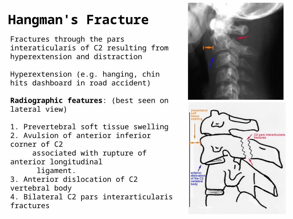
Hangman's FractureFractures through the pars interaticularis of C2 resulting from hyperextension and distraction
Hyperextension (e.g. hanging, chin hits dashboard in road accident)
Radiographic features: (best seen on lateral view)
1. Prevertebral soft tissue swelling2. Avulsion of anterior inferior corner of C2 associated with rupture of anterior longitudinal ligament. 3. Anterior dislocation of C2 vertebral body4. Bilateral C2 pars interarticularis fractures

Bilateral Facet Dislocation
Complete anterior dislocation of vertebral body resulting from extreme hyperflexion injury
Associated with a very high risk of cord damage

Unilateral Facet Dislocation
Facet joint dislocation and rupture of the apophyseal joint ligaments resulting from rotatory injury
Mechanism: simultaneous flexion and rotation

Burst FractureResults from axial compression
Injury to spinal cord is common due to displacement of posterior fragments
CT is required for all patient to evaluate extent of injury

INFECTIONS

Usually the result of blood–borne agents Especially from lung and urinary tract Most common pathogen is staphylococcus, Streptococcus less commonGram-negative rods in IV drug abusers or immunocompromised patients
E. Coli Proteus Non-pyogenic
Tuberculosis Coccidioidomycosis
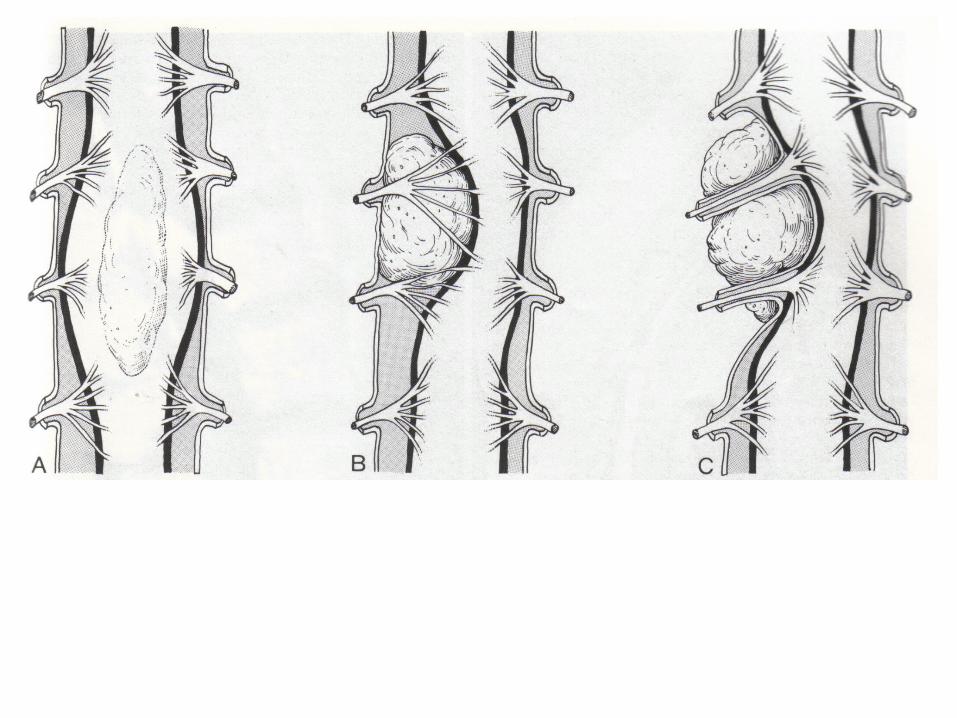
May occur after invasive procedure like Surgery, Discography, Myelography In children, infection begins in vascularized disc In adults, in anterior inferior corner of vertebral body with spread across disk to adjacent vertebral endplate Site of involvement
L3/4 L4/5 Unusual above T9 Usually involvement of one disk space (occasionally 2)
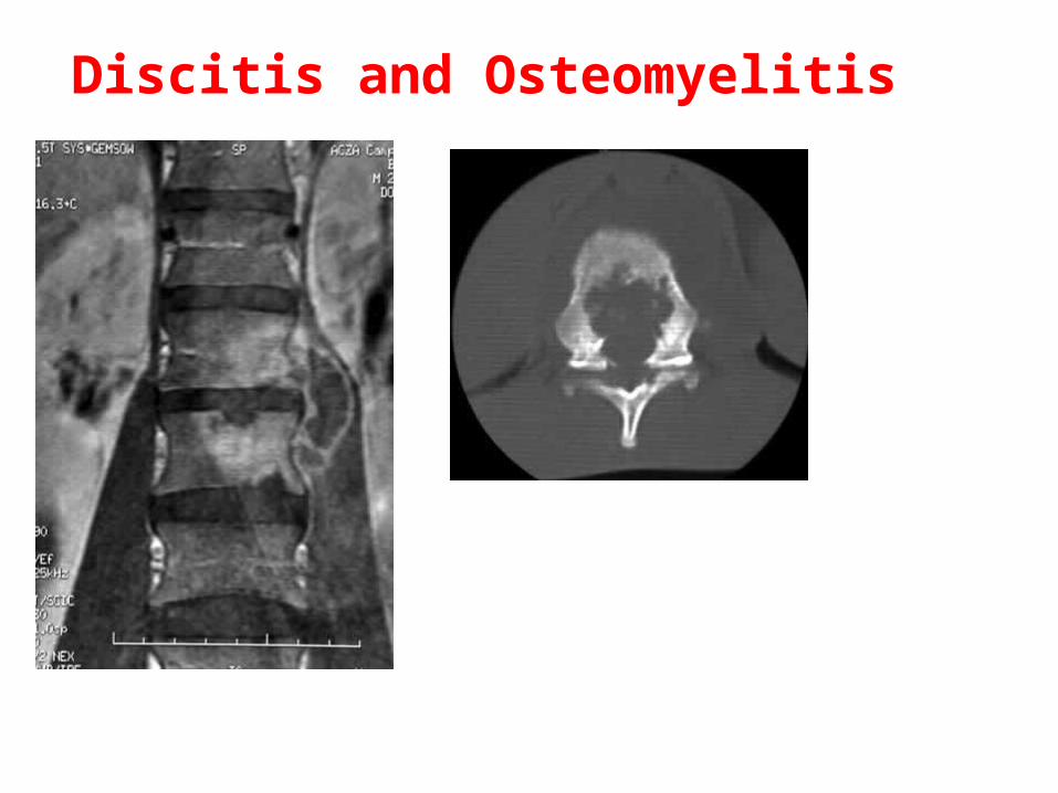
Discitis and Osteomyelitis

IMAGING FINDINGSPLAIN FILMS
Narrowing and destruction of an intervertebral disk Earliest plain film sign
Indistinct adjacent endplates with destruction Often associated with bony sclerosis of the two contiguous vertebral bodies Paravertebral soft tissue mass Endplate sclerosis (during healing phase beginning anywhere from 8 weeks to 8 months after onset) Bone fusion after 6 months to 2 years
MRI Bone marrow edema in infected vertebrae, discs and paraspinal soft tissues
Dark on T1 and bright on T2 imagesEnhancement of inflammed tissues after contrastFluid collections (abscesses) are common
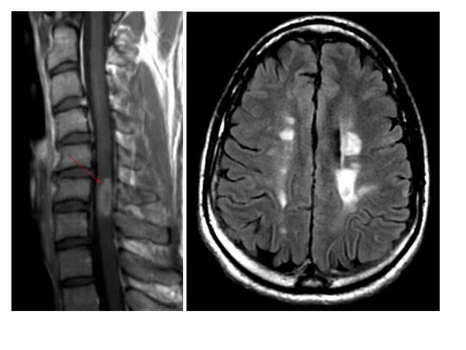
Discitis and Osteomyelitis
c
Discitis and Osteomyelitis

A. Sagittal T1 MRI shows decreased signal of vertebral bodies and disc with end plate destructionB. Sagittal T2 MRI shows increased signal in corresponding areas with anterior subligamentous abscess, epidural involvement and extension of inflammation in T6 with preserved endplateC. Axial contrast-enhanced T1 MRI shows peripheral enhancement of paravertebral abscess and marked enhancement of epidural tissues causing displacement of spinal cordD. CT shows lytic lesion in vertebral body and paravertebral abscess with calcifications

TUMORS

AJNR


THANKS