Embed Size (px)
Citation preview

IMAGInGinsigHtsolutions, products and news from Matrox Imaging
Product news:coaXpress (cXp) frame grabber debuts
Case study: Machine vision helps port terminals increase productivity
the vision squad files: GpU processing using MIl
Vol. 12 no. 2
Celebrating 35 years
2 Celebrating 35 years of vision: contents / IMAGInG insigHt Vol. 12 no. 2
CONTENTS
Corporate headquarters:Canada and U.S.A. Matrox Electronic Systems Ltd.1055 St. Regis Blvd.Dorval, QC H9P 2T4CanadaTel: +1 (514) 685-2630 Fax: +1 (514) 822-6273
GermanyMatrox Electronic Systems GmbH Inselkammerstr. 8 D-82008 Unterhaching Germany Tel: +49 (0) 89 / 62170 0 Fax: +49 (0) 89 / 614 97 43
Offices:Europe, Middle East & AfricaMatrox VITE LimitedChaplin HouseWidewater PlaceMoorhall RoadHarefieldMiddlesex United Kingdom, UB9 6NSTel: +44 (0) 1895 827300Fax: +44 (0) 1895 827301
Publisher: Matrox ImagingEditor / Marketing Communications: Catherine Overbury
Matrox Graphic Designers: Julie Lefort, Roland Joly
Reproduction in whole or in part, without the prior written permission of Matrox Imaging, is prohibited. For more information on articles published in this issue, or to
share your comments, please contact the editor:
Tel: 1-514-685-7230 ext. 2459 Email: [email protected]
R
About Us . . . . . . . . . . . . . . . . . . . . . . . . . . . . . . . . . . . . . . . . . . . . . 03Celebrating 35 years of vision Product News . . . . . . . . . . . . . . . . . . . . . . . . . . . . . . . . . . . . . . . . 04Matrox Imaging announces CoaXPress (CXP) frame grabber and discusses new standard
Interview . . . . . . . . . . . . . . . . . . . . . . . . . . . . . . . . . . . . . . . . . . . . . 06Laval Tremblay, Matrox Imaging Vice President, Engineering, talks trends in machine vision
Case Study: IBG Automation GmbH . . . . . . . . . . . . . . . . . . . . . . . . . . . . . 07Smart camera helps the wheels go ’round and ’round
Case Study: MicroView & LingZhi . . . . . . . . . . . . . . . . . . . . . . . . . . . . . . . 10Machine vision makes ports more productive
The Vision Squad Files . . . . . . . . . . . . . . . . . . . . . . . . . . . . . 13GPU processing using MIL
Want to subs cribe? Go to: www.matroximaging.com/newsletter
07
04
06
10
IMAGInG insigHt Vol. 12 no. 2 / Celebrating 35 years of vision: ABoUt Us 3
In the beginning...Co-founded in Montreal, Canada by electrical engineers Branko Matic and Lorne Trottier, Matrox began as a pioneer of microprocessor technology with the 1976 release of Video RAM, the market’s first specialized video display device. In 1982, Matrox introduced the Multibus-compatible RGB-GRAPH–an extremely successful color graphics and video frame grabber card duo. This product opened up a wide range of applications for the imaging, graphics, and video markets, thus paving the way for future Matrox products.
The PC platformIn 1983, the megapixel display of the GXB 1000 series quadrupled the number of pixels supported by any other graphics card at the time. Two year later, Matrox introduced the industry’s first frame grabber for the PC platform, the PIP-512, and in 1986, the MVP-AT–the industry’s first hardware-accelerated image processing board set.
Another major breakthrough for Matrox occurred in 1986 when the company won a $72 million contract with the US Army to develop and manufacture an Electronic Information Delivery System (EIDS). EIDS was the world’s first multimedia PC that combined color graphics, video, digital audio, and computer data on a single laser disk. This project launched Matrox into the field of multimedia content creation and delivery.
Processing milestonesMatrox introduced the Image Series modular image processing platform in 1989, setting new industry standards with six custom chips that provided real-time pipelined neighborhood processing. In 1993, the Matrox Imaging Library (MIL) was released as the industry’s first hardware-independent library. And almost 20 years later, MIL remains the toolkit of choice for developing machine vision, image analysis, and medical imaging applications. The multiple award-winning Genesis vision processors family launched in 1996. Integrating flexible acquisition, real-time processing, custom ASICS, and high-resolution display, the vision processor established a new performance standard with its highly pipelined, parallel-processing architecture. The Meteor-II family of high-performance, fully programmable PCI frame grabbers for cost-sensitive applications debuted in 1997 and remains a best seller to this day.
Integrated solutionsIn 1999, Matrox expanded into new markets with its 4Sight family of industrial vision computers that integrates capture, processing, display, networking, and general purpose I/O on one compact platform. Several years later, Matrox took this concept of integration even further, with the launch of the Matrox Iris smart camera family. In 2008, the next generation of this camera, the Iris GT, debuted with Design Assistant, an intuitive, versatile, and extendable integrated development environment (IDE).
Matrox continues to innovate by providing such products as the Supersight high-performance computing (HPC) platform that integrates CPUs, GPUs, FPGAs, and frame grabbers on a configurable high-speed switched fabric. Matrox also stays true to its board-level roots by developing video capture and display cards for HD and SD video, and frame grabbers for the latest interface standards like CoaXPress (CXP).
Moving forwardOffices in the United Kingdom, Ireland, Germany, and Hong Kong, and a network of sales representatives in 20-plus countries, guarantee that Matrox has a strong international presence. Matrox Imaging’s dynamic teams of engineers, sales and marketing professionals, technical support representatives, operations experts, and production staff–both at headquarters and abroad–ensure the division’s ongoing growth.
The corporate strategies that have served Matrox Imaging so well over the past 35 years–technical expertise, a bold commercial approach, and an unwavering commitment to our customers will continue.
The future is bright.
Celebrating 35 years of vision
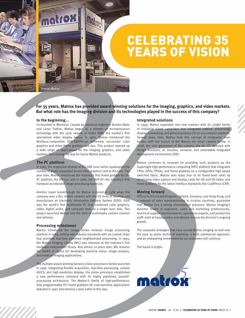
For 35 years, Matrox has provided award-winning solutions for the imaging, graphics, and video markets. But what role has the Imaging division and its technologies played in the success of this company?
Source: Matrox
4 Celebrating 35 years of vision: prodUct news / IMAGInG insigHt Vol. 12 no. 2
At Vision 2011, Matrox Imaging announced the Matrox Radient eV-CXP, a cost-effective CoaXPress (CXP) frame grabber derived from the original Matrox Radient family. By combining a field proven design with the new CXP interface, the Matrox Radient eV-CXP offers a dependable high-performance image capture solution for today and tomorrow.
The Matrox Radient eV-CXP provides four independent CXP links through the required BNC connectors. This allows for simultaneous capture from up to four cameras each running at different CXP speeds (i.e. 1.25, 2.5, 3.125, 5.0 or 6.25 Gbps). For high-bandwidth applications, the frame grabber can also capture from a single camera transmitting image data at up to 25 Gbps using link aggregation.
To handle high data rates, the Matrox Radient eV-CXP has a PCIe® 2.0 x8 host interface–with a peak transfer rate of up to 4GB/s–combined with up to 4GB SDRAM of on-board buffering. This ensures reliable capture to host memory. In cases with extremely high video frame rates (i.e., thousands of frames per second), users have the option of relying on the Matrox Radient eV-CXP’s on-board MicroBlaze™ soft processor to offload image acquisition management from the host CPU. The frame grabber can also offload the host CPU from having to perform image pre-processing (i.e. Bayer interpolation, color space conversion and LUT mapping) tasks.
Beyond host offloading, the Matrox Radient eV-CXP simplifies overall system integration by providing camera power, trigger and control over each CXP link, as well as four independent sets of auxiliary I/O for interfacing with rotary encoders, photoelectric sensors and strobe controllers. By having the primary set of auxiliary I/Os on the same bracket as the BNC connections, the Matrox Radient eV-CXP offers a true single PCIe® slot solution for single camera applications.
Like all Matrox frame grabbers, the Matrox Radient eV-CXP has a managed lifecycle offering long term availability to help reduce development and validation costs. This value-packed high-performance CXP frame grabber is fully supported by the Matrox Imaging Library (MIL) toolkit on 32-bit and 64-bit Windows® 7 and Linux®.
To learn more about the Matrox Radient eV-CXP, please contact your local Matrox Imaging representative.
White paper: Effectively applying high-performance computing (HPC) to imaging
Applications with image resolutions, data rates and analysis requirements that exceed the capabilities of a typical workstation computer continue to exist to this day. Moreover, developers must decide how to select and best use the processing technologies—multi-core CPU, GPU and FPGA—at their disposal. The suitability of a scalable heterogeneous computing platform for demanding applications will be examined by way of a representative scenario.
Download the whitepaper at: www.matrox.com/imaging/hpc
MaTrOx radiENT EV-CxP COaxPrESS (CxP) fraME grabbEr dEbuTS
ProDUCt neWs

IMAGInG insigHt Vol. 12 no. 2 / Celebrating 35 years of vision: prodUct news 5
Imaging Insight recently interviewed Matrox Imaging Product Manager, Michael Chee, Hardware Design Director, Donald Connolly, and Software Development Director, Stephane Maurice to learn about the emergence and significance of CoaXPress, a new camera interface standard.
Imaging Insight: Let’s begin by describing CoaXPress (CXP).Michael: CoaXPress (CXP) is an asymmetric high speed point-to-point serial communication standard for transmitting video and still images. Originally specified by a consortium of camera and frame grabber vendors, it was adopted and is now maintained by the JIIA (Japan Industrial Imaging Association). In April 2011, it was approved as an international standard through the G3 Agreement (Cooperation Agreement on Global Coordination of Machine Vision Standardization) between the AIA (Automated Imaging Association), the EMVA (European Machine Vision Association) and the JIIA.
Imaging Insight: What advantages does CXP offer over other industrial camera interface standards like Camera Link® and GigE Vision®?Donald: CXP delivers greater bandwidth while addressing the other vital requirements which are reach, determinism, robustness, ease of upgrade, complexity and cost. To date, Camera Link® has provided the most bandwidth at 850 Mbytes per second (in 10 tap mode). This is not enough for the new generation of larger and faster image sensors.
CXP has a full duplex design. The downlink (from camera to frame grabber) can transmit image data at up to 6.25 Gbits/sec (Gbps). The uplink (from frame grabber to camera) can handle command and control data at up to 20 Mbits/sec. Greater downlink performance can be achieved by combining links. One can, for example, join four links to obtain a peak bandwidth of 25 Gbps.
Camera Link® is often criticized for having a maximum cable length of 10 meters (without the added burden of repeaters), which is not even at the maximum operating speed of 85 MHz. CXP uses coax cabling and new transceiver technology to cover distances over 100 meters (without the need for repeaters). Gigabit Ethernet (used by GigE Vision®) has a similar range to CXP but it lacks the low latency and low jitter trigger characteristics of CXP.
The flexibility of coaxial cable makes CXP well suited for applications where a camera is mounted on a moving arm. Coax has the added benefit of already being installed in many analog systems, which makes it easier to move these to digital with CXP. Finally, CXP helps reduce cable complexity and cost by offering triggering and 13W of power over the same coax cable.
Stephane: Like GigE Vision®, CXP leverages the GenICam™ software interface to provide a standard, yet flexible way to identify and control camera features. This simplifies the integration work for both vendors and users.
Imaging Insight: What applications does CXP target?Michael: Medical and defense applications are good candidates because their analog implementations routinely make use of coax cabling. With CXP, these applications can be more easily upgraded to use faster, higher-resolution and higher-fidelity digital imaging technology. CXP’s additional bandwidth also provides high-end machine vision applications with the ability to handle higher production rates and perform finer inspections.
Imaging insight: How do you see CXP evolving? Donald: The technology that was available when the standard was first put together, particularly the SERDES (serializers/deserializers) inside FPGA devices, limit the speed of a single downlink to 6.25 Gbps. The SERDES in next generation FPGA devices will handle higher speeds–possibly enabling up to 12.5 Gbps per downlink. There is also a working group looking at improving signal integrity to make use of these higher speeds over longer distances (using a single hop).
Other users may want CXP to support image transmission at lower data rates (i.e., below 1.25 Gbps or CXP-1) over even longer distances (i.e., hundreds of meters), thereby providing an appropriate replacement for applications using legacy analog cameras.
Besides the work being done on signal integrity to further boost speed and distance, there is work being done on cabling and interconnect. Although link aggregation is a good way of increasing bandwidth, the present need to use four BNC connectors makes it somewhat cumbersome. This is why the technical committee has set up a working group to investigate solutions for integrating multiple links into a single compact connector.
Imaging Insight: Thank you for taking the time to speak with us on this topic.
Resources: CoaXPress: www.coaxpress.comJIIA: www.jiia.orgEMVA: www.emva.orgAIA: www.machinevisiononline.org
TECh Talk: COaxPrESS
R

6 Celebrating 35 years of vision: InterVIew / IMAGInG insigHt Vol. 12 no. 2
Q: Has the machine-vision industry recovered from the global recession?A: The industry has recovered exceptionally well as a result of the manufacturing sector leading the overall recovery. Major players in the industry—including Matrox Imaging—are experiencing record sales. Manufacturers, especially those in the electronics and semiconductor sectors, better managed their inventories, having learned from the dot-com bubble. This discipline has resulted in an upsurge in demand for machine-vision components. Moreover, although the latest recession severely affected all economic activity, it had a greater negative impact on the financial, real-estate, and construction sectors. The question to ask, though, is how long can this strong resurgence be sustained?
Q: Which industries are leading the way in adopting inspection solutions based on machine vision?A: Industries like semiconductors, electronics, and flat-panel displays continue to be big consumers of machine-vision inspection technology. Industries that are tightly regulated and those that need to mitigate potential liability—like food and beverage and pharmaceuticals—are also increasingly using vision. Plus, we’re seeing a rebound in automotive demand with the growth in electronics content for battery management, start/stop systems, onboard infotainment, and communications. LED lighting and new power-train investments, which promote smarter use of our scarce energy resources, are also creating new demand for machine vision in the automotive sector.
Q: What are some typical applications for the Matrox Supersight system?A: The Matrox Supersight computing platform is designed for high-throughput and computationally demanding vision applications, such as semiconductor wafer and mask inspection and flat-panel-display inspection. Among its key features is a unique PCIe Gen 2 switched-fabric backplane that removes I/O bottlenecks between installed devices. Supersight is also well-suited to medical imaging, where applications demand high data and data/task-level parallelism and employ multiple CPU cores or GPU accelerator boards, or a mix of both of these processing technologies.
Q: Can you briefly sort out the landscape of vision interface standards?A: For moderate-bandwidth applications, GigE Vision has become the preferred choice over IEEE 1394 and USB because of cabling advantages. GigE provides enough bandwidth for all but the highest-speed cameras, and cables can be as long as 100 m. Camera Link is holding its own for more exacting applications because of the better determinism, despite the fact that it requires specialized computer-interface hardware.
For high bandwidth, Camera Link is still king, although it is losing some of its dominance. This situation has prompted the creation of the CoaXPress and Camera Link HS standards, which offer greater bandwidth over longer distances. Initially, we see CoaXPress as being complementary to Camera Link, but we do see it eroding the Camera Link market as time goes on. CoaXPress offers several advantages, such as the ability to transfer higher data rates over longer distances with simplified cabling.
Q: How have smart cameras changed the machine-vision field?A: It is not the camera hardware that is changing machine vision, but rather the software environment that is associated with the camera. Customers have certain expectations, such as quick-and-easy application development, which includes algorithms, the human-machine interface, and connections to other equipment. Software plays a major role in meeting those needs.
Q: Where are frame grabbers still prevalent?A: High-bandwidth interfaces like CoaXPress and Camera Link HS will still require frame grabbers. Frame grabbers are also needed in such vision applications as semiconductor and flat-panel inspection, which require high resolution and high-data-rate cameras.
Visit www.matrox.com/imaging/tmw to read the rest of the interview with Laval Tremblay.
This interview first published in the September 2011 issue of Test & Measurement World. Used with permission.
intervieW With a teChnology leaDer
Larry Maloney, Contributing Editor, Test & Measurement World, conducted an exclusive interview with Laval Tremblay, Matrox Imaging Vice President, Engineering, on trends in machine-vision applications.

IMAGInG insigHt Vol. 12 no. 2 / Celebrating 35 years of vision: cAse stUdY 7
sMart CaMera helPs the Wheels go ’roUnD anD ’roUnD
Assembly system fits and mounts wheels onto continuously moving vehicles By automating the wheel installation process, automotive manufacturers not only see labor costs drastically reduced, but overall manufacturing quality improves as assembly errors are eliminated. Source: IBG Automation GmbH
8 Celebrating 35 years of vision: cAse stUdY / IMAGInG insigHt Vol. 12 no. 2
MaChiNE ViSiON-baSEd aSSEMbly SySTEM fiTS aNd MOuNTS whEElS ONTO CarS iN CONTiNuOuS OPEraTiONUsing manual assembly methods to mount wheels onto cars in continuous operation is extremely costly for automotive manufacturers. This is mainly because several assembly workers are required to perform the work.
IBG Automation GmbH (Neuenrade, Germany), an automation solutions provider, has designed a sophisticated assembly system for the automotive industry that automatically fits and mounts wheels onto car bodies moving continuously along the line. This highly flexible system can be used for a variety of vehicles and wheel types. By automating this process, automotive manufacturers not only see labor costs drastically reduced, but overall manufacturing quality improve as assembly errors are eliminated.
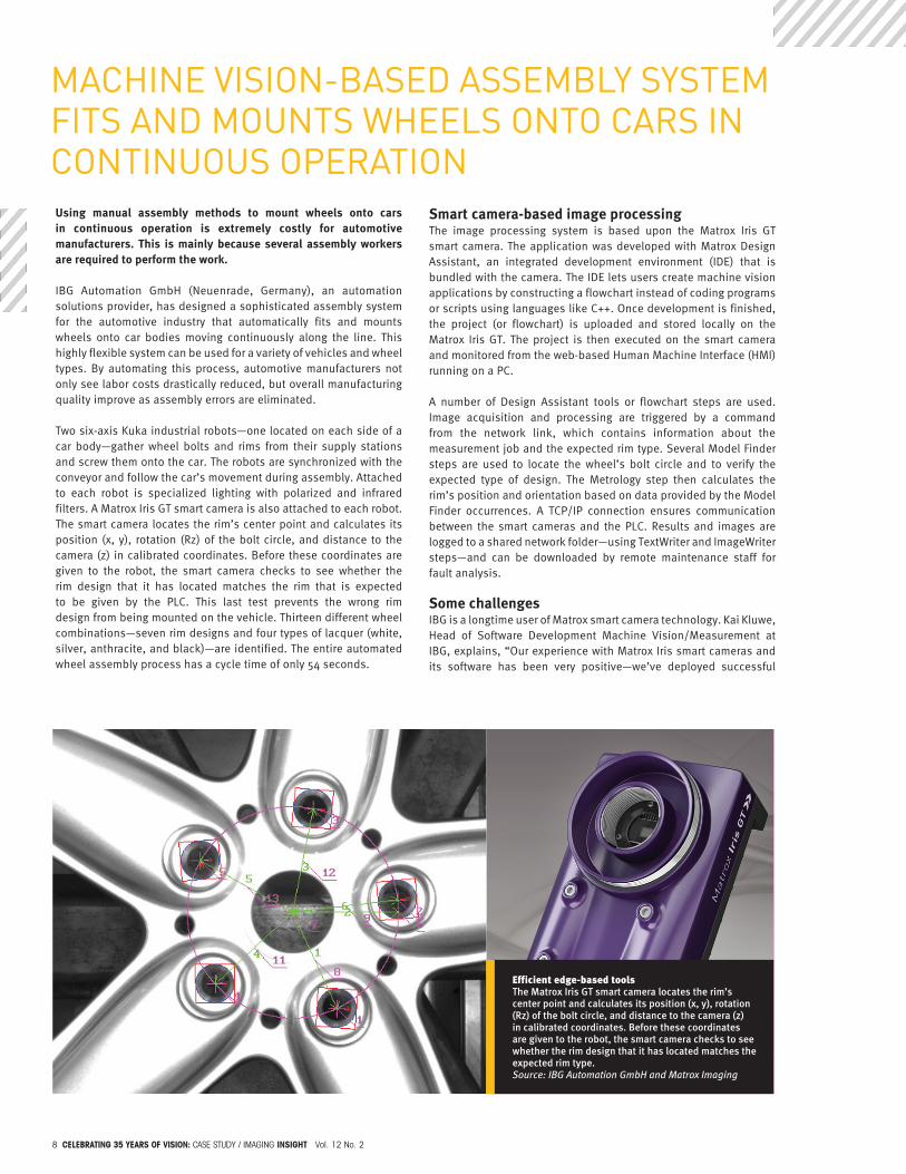
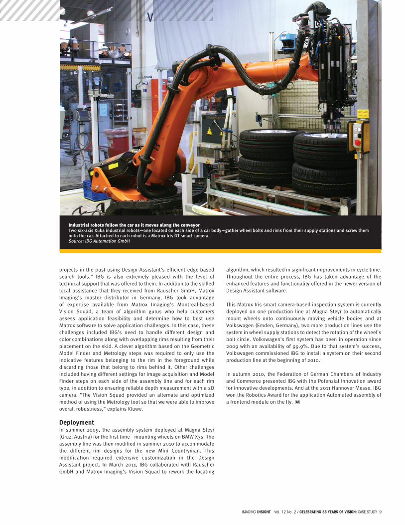
Two six-axis Kuka industrial robots—one located on each side of a car body—gather wheel bolts and rims from their supply stations and screw them onto the car. The robots are synchronized with the conveyor and follow the car’s movement during assembly. Attached to each robot is specialized lighting with polarized and infrared filters. A Matrox Iris GT smart camera is also attached to each robot. The smart camera locates the rim’s center point and calculates its position (x, y), rotation (Rz) of the bolt circle, and distance to the camera (z) in calibrated coordinates. Before these coordinates are given to the robot, the smart camera checks to see whether the rim design that it has located matches the rim that is expected to be given by the PLC. This last test prevents the wrong rim design from being mounted on the vehicle. Thirteen different wheel combinations—seven rim designs and four types of lacquer (white, silver, anthracite, and black)—are identified. The entire automated wheel assembly process has a cycle time of only 54 seconds.
Smart camera-based image processingThe image processing system is based upon the Matrox Iris GT smart camera. The application was developed with Matrox Design Assistant, an integrated development environment (IDE) that is bundled with the camera. The IDE lets users create machine vision applications by constructing a flowchart instead of coding programs or scripts using languages like C++. Once development is finished, the project (or flowchart) is uploaded and stored locally on the Matrox Iris GT. The project is then executed on the smart camera and monitored from the web-based Human Machine Interface (HMI) running on a PC.
A number of Design Assistant tools or flowchart steps are used. Image acquisition and processing are triggered by a command from the network link, which contains information about the measurement job and the expected rim type. Several Model Finder steps are used to locate the wheel’s bolt circle and to verify the expected type of design. The Metrology step then calculates the rim’s position and orientation based on data provided by the Model Finder occurrences. A TCP/IP connection ensures communication between the smart cameras and the PLC. Results and images are logged to a shared network folder—using TextWriter and ImageWriter steps—and can be downloaded by remote maintenance staff for fault analysis.
Some challengesIBG is a longtime user of Matrox smart camera technology. Kai Kluwe, Head of Software Development Machine Vision/Measurement at IBG, explains, “Our experience with Matrox Iris smart cameras and its software has been very positive—we’ve deployed successful
Efficient edge-based tools The Matrox Iris GT smart camera locates the rim’s center point and calculates its position (x, y), rotation (Rz) of the bolt circle, and distance to the camera (z) in calibrated coordinates. Before these coordinates are given to the robot, the smart camera checks to see whether the rim design that it has located matches the expected rim type. Source: IBG Automation GmbH and Matrox Imaging
IMAGInG insigHt Vol. 12 no. 2 / Celebrating 35 years of vision: cAse stUdY 9
projects in the past using Design Assistant’s efficient edge-based search tools.” IBG is also extremely pleased with the level of technical support that was offered to them. In addition to the skilled local assistance that they received from Rauscher GmbH, Matrox Imaging’s master distributor in Germany, IBG took advantage of expertise available from Matrox Imaging’s Montreal-based Vision Squad, a team of algorithm gurus who help customers assess application feasibility and determine how to best use Matrox software to solve application challenges. In this case, these challenges included IBG’s need to handle different design and color combinations along with overlapping rims resulting from their placement on the skid. A clever algorithm based on the Geometric Model Finder and Metrology steps was required to only use the indicative features belonging to the rim in the foreground while discarding those that belong to rims behind it. Other challenges included having different settings for image acquisition and Model Finder steps on each side of the assembly line and for each rim type, in addition to ensuring reliable depth measurement with a 2D camera. “The Vision Squad provided an alternate and optimized method of using the Metrology tool so that we were able to improve overall robustness,” explains Kluwe.
DeploymentIn summer 2009, the assembly system deployed at Magna Steyr (Graz, Austria) for the first time—mounting wheels on BMW X3s. The assembly line was then modified in summer 2010 to accommodate the different rim designs for the new Mini Countryman. This modification required extensive customization in the Design Assistant project. In March 2011, IBG collaborated with Rauscher GmbH and Matrox Imaging’s Vision Squad to rework the locating
algorithm, which resulted in significant improvements in cycle time. Throughout the entire process, IBG has taken advantage of the enhanced features and functionality offered in the newer version of Design Assistant software.
This Matrox Iris smart camera-based inspection system is currently deployed on one production line at Magna Steyr to automatically mount wheels onto continuously moving vehicle bodies and at Volkswagen (Emden, Germany), two more production lines use the system in wheel supply stations to detect the rotation of the wheel’s bolt circle. Volkswagen’s first system has been in operation since 2009 with an availability of 99.9%. Due to that system’s success, Volkswagen commissioned IBG to install a system on their second production line at the beginning of 2010.
In autumn 2010, the Federation of German Chambers of Industry and Commerce presented IBG with the Potenzial Innovation award for innovative developments. And at the 2011 Hannover Messe, IBG won the Robotics Award for the application Automated assembly of a frontend module on the fly.
Industrial robots follow the car as it moves along the conveyor Two six-axis Kuka industrial robots—one located on each side of a car body—gather wheel bolts and rims from their supply stations and screw them onto the car. Attached to each robot is a Matrox Iris GT smart camera. Source: IBG Automation GmbH
10 Celebrating 35 years of vision: cAse stUdY / IMAGInG insigHt Vol. 12 no. 2
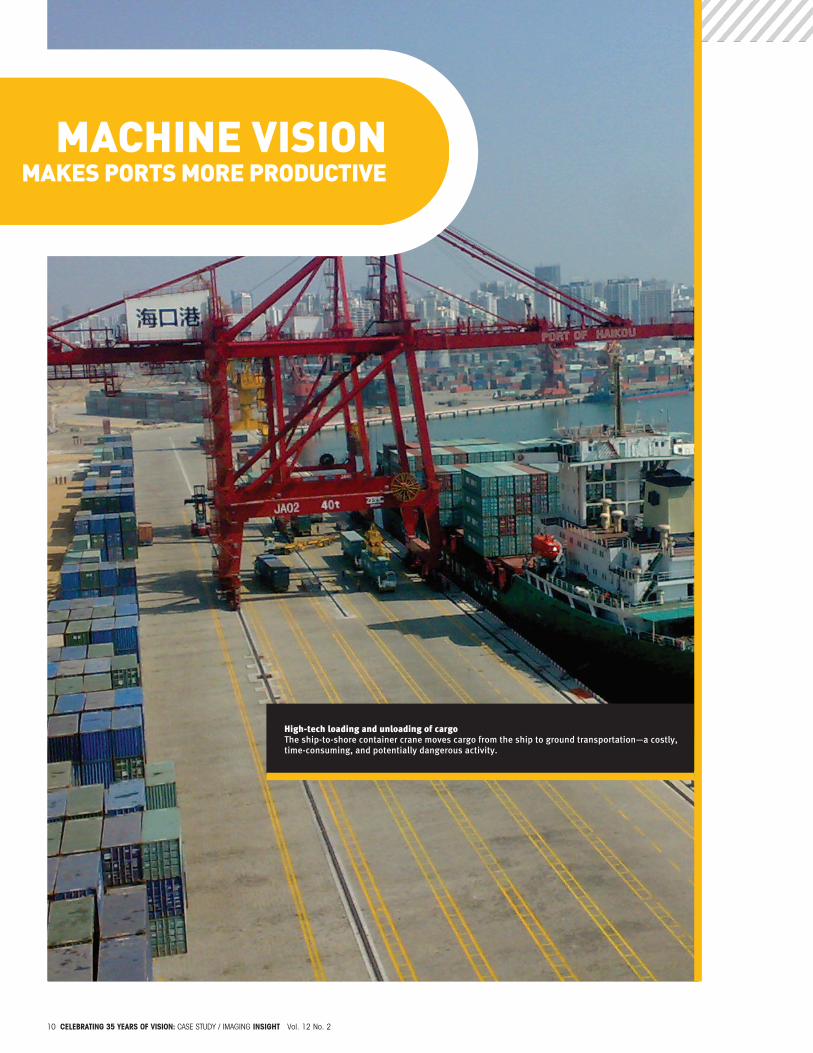
High-tech loading and unloading of cargoThe ship-to-shore container crane moves cargo from the ship to ground transportation—a costly, time-consuming, and potentially dangerous activity.
MaChine vision MaKes Ports More ProDUCtive
IMAGInG insigHt Vol. 12 no. 2 / Celebrating 35 years of vision: cAse stUdY 11
Ship-to-shore container cranesIn today’s highly competitive world economy, customers require fast, low cost, and dependable shipping of cargo. In response to these demands, port terminals are automating their container handling processes and investing in high-tech loading and unloading equipment. This is in the ports’ best interests, since it allows them to improve efficiency by minimizing the amount of time that ships are docked in the berths.
Ship-to-shore (STS) container craneOne of the most significant investments in the port terminal system is the ship-to-shore crane. The ship-to-shore (STS) container cranes move cargo from the ship to ground transportation—a costly, time-consuming, and potentially dangerous activity.
STS container cranes are classified by their degrees of automation. Conventional cranes are manually operated. The operators are highly-skilled, but because they sit in crane cabins for long periods of time performing the same tasks, operators can experience fatigue and boredom. This inattention can result in accidents that injure dock workers, damage cargo, and delay load handling.
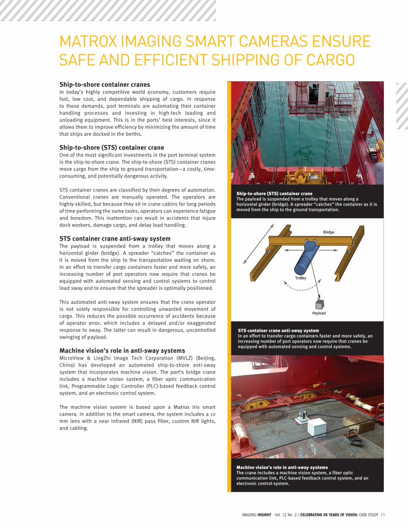
STS container crane anti-sway systemThe payload is suspended from a trolley that moves along a horizontal girder (bridge). A spreader “catches” the container as it is moved from the ship to the transportation waiting on shore. In an effort to transfer cargo containers faster and more safely, an increasing number of port operators now require that cranes be equipped with automated sensing and control systems to control load sway and to ensure that the spreader is optimally positioned.
This automated anti-sway system ensures that the crane operator is not solely responsible for controlling unwanted movement of cargo. This reduces the possible occurrence of accidents because of operator error, which includes a delayed and/or exaggerated response to sway. The latter can result in dangerous, uncontrolled swinging of payload.
Machine vision’s role in anti-sway systemsMicroView & LingZhi Image Tech Corporation (MVLZ) (Beijing, China) has developed an automated ship-to-shore anti-sway system that incorporates machine vision. The port’s bridge crane includes a machine vision system, a fiber optic communication link, Programmable Logic Controller (PLC)-based feedback control system, and an electronic control system.
The machine vision system is based upon a Matrox Iris smart camera. In addition to the smart camera, the system includes a 12 mm lens with a near infrared (NIR) pass filter, custom NIR lights, and cabling.
Ship-to-shore (STS) container craneThe payload is suspended from a trolley that moves along a horizontal girder (bridge). A spreader “catches” the container as it is moved from the ship to the ground transportation.
STS container crane anti-sway systemIn an effort to transfer cargo containers faster and more safely, an increasing number of port operators now require that cranes be equipped with automated sensing and control systems.
Machine vision’s role in anti-sway systemsThe crane includes a machine vision system, a fiber optic communication link, PLC-based feedback control system, and an electronic control system.
MaTrOx iMagiNg SMarT CaMEraS ENSurE SafE aNd EffiCiENT ShiPPiNg Of CargO

12 Celebrating 35 years of vision: cAse stUdY / IMAGInG insigHt Vol. 12 no. 2
The Matrox Iris smart camera is mounted on the trolley, while the light sources on the spreader are used as markers. The camera grabs images of the markers continuously and calculates the center point of two markers in real time. This information is transmitted over an RS-232 link, itself converted to a fiber optic link (and then back to an RS-232 link) to reliably cover the long distance between the smart camera and PLC. The location of the center point is continuously provided to the PLC. The PLC gives commands to the electronic control system, which regulates trolley movement so that container sway is reduced.
The working distance from the smart camera to the markers on the spreader is between 3 m and 50 m. The view angle of the camera is 28°. The spreader should always be in the camera’s field of view. The system precision is 10 mm when the working distance is 50 m. The control frequency of the trolley is 20 Hz.
Smart camera-based vision systemA smart camera-based vision system is ideally suited for meeting the STS system’s precision and control frequency requirements. Ms. Xing Xiao, Technical Support Manager, MVLZ comments, “There is no space in the system for a traditional, PC-based vision system, plus the PLC only needs the markers’ positions for control. A smart camera can do all the work—grabbing, processing, and outputting the results via the RS-232 port.”
The sensor on the Matrox Iris smart camera can operate in the NIR range. Two custom NIR lamps are used as markers for imaging processing. “We chose NIR,” Ms. Xiao continues, “because it is immune to the effects of bad weather, like rain. A powerful light source is necessary to ensure that the markers are kept in the foreground, while everything else in the field of view is seen as background.”
The application was developed with Matrox Design Assistant, an integrated development environment (IDE) that is bundled with the smart camera. Design Assistant lets users create machine vision applications by constructing a flowchart instead of coding programs or scripts. “The smart camera software is very easy to use and does not require highly-skilled programmers. We simply initialize the serial port, grab the raw image, perform blob analysis, and write to the serial port,” explains Ms. Xiao.
DeploymentThe ship-to-shore anti-sway system is used in port terminals in China, including Zhenjiang, Guangdong province and Haikou, Hainan province. Looking to the future, more and more port authorities are demanding that their ship-to-shore container cranes include an automated anti-sway system in their quest to process containers faster and more efficiently.
All images courtesy of MicroView & LingZhi Image Tech Corporation (MVLZ).
Smart camera-based vision systemThe machine vision system is based upon a Matrox Iris smart camera. The light sources on the spreader are used as markers. The location of the markers’ center point is continuously provided to the PLC.
STS system’s precision and control requirementsBecause there is no space in the system for a PC-based vision system and because the PLC only needs the markers’ positions for control, a smart camera can do all the work—grabbing, processing, and outputting the results.
Processed image of light sources used as markersThe application involves initializing the serial port, grabbing the raw image of the markers, performing blob analysis, and writing to the serial port.
IMAGInG insigHt Vol. 12 no. 2 / Celebrating 35 years of vision: the VIsIon sqUAd fIles 13
gPu PrOCESSiNg uSiNg Mil
the vision sQUaD files
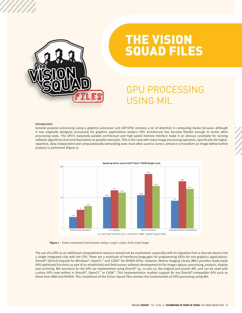
IntroductionGeneral purpose processing using a graphics processor unit (GP-GPU) receives a lot of attention in computing media because–although it was originally designed exclusively for graphics applications–today’s GPU architecture has become flexible enough to tackle other processing tasks. The GPU’s massively parallel architecture and high-speed memory interface make it an obvious candidate for running software algorithms that lend themselves to parallel execution. This is the case with many image processing operators, specifically the highly-repetitive, data-independent and computationally-demanding ones most often used to correct, enhance or transform an image before further analysis is performed (Figure 1).
Figure 1 – Some comparative benchmarks using a 2048 x 2048 x 8-bit sized image.
The use of a GPU as an additional computational resource should not be overlooked–especially with its migration from a discrete device into a single integrated chip with the CPU. There are a multitude of interfaces/languages for programming GPUs for non-graphics applications: DirectX® (DirectCompute) for Windows®, OpenCL™ and CUDA™ for NVIDIA GPUs. However, Matrox Imaging Library (MIL) provides ready-made GPU-optimized functions as part of an established and field-proven software development kit for image capture, processing, analysis, display and archiving. MIL functions for the GPU are implemented using DirectX® (9, 10 and 11), the original and proven API, and can be used with custom GPU code written in DirectX®, OpenCL™ or CUDA™. This implementation enables support for any DirectX®-compatible GPU such as those from AMD and NVIDIA. This installment of the Vision Squad Files reviews the fundamentals of GPU processing using MIL.
The
VISIONSQUAD
The
VISIONSQUAD
The
57.8
100
Speed-up factor versus Intel® Xeon® E5620 (single core)
10.4111.82
7.9
17.2
33.6
14.4
23.6
19.1
10
2.31
4
5.3
1Addition (with saturation) LUT mapping 15x15 convolution Warp (with bilinear interpolation)
2 x Intel® Xeon® E5645 (12 cores) ATI FirePro™ V8800 NVIDIA® Quadro® 6000

14 Celebrating 35 years of vision: the VIsIon sqUAd fIles / IMAGInG insigHt Vol. 12 no. 2
Setup and useBefore a MIL function can run on a GPU, the application must first explicitly allocate the MIL GPU system followed by the necessary suitable buffers on this system. The maximum size of a buffer on a GPU is dictated by the GPU itself with newer GPUs supporting larger buffer sizes. The computer graphics effect, or GPU binary code, for the MIL function must then be generated and loaded onto the GPU. Depending upon how the system is allocated, this can be accomplished in one of two ways. If the system is allocated using the M_PARTIAL (or M_DEFAULT) method, then the effect is generated and loaded onto the GPU the first time the MIL function is called to run on the GPU. This on-demand approach greatly accelerates the overall allocation of the system but penalizes the first execution of the MIL function on the GPU. If the system is allocated using the M_COMPLETE method, then all the supported effects are generated and loaded onto the GPU when the system is allocated. This all-at-once approach significantly slows down the allocation of the system but does not penalize the first call to a MIL function on the GPU. Which effects are automatically generated and loaded during this system allocation can be adjusted through MILConfig (Figure 2).
Figure 2 – Listing available GPU effects through MILConfig.
If an effect is deselected but the corresponding MIL function is still asked to run on the GPU, MIL will compensate and transparently execute the function on the host system (i.e., CPU).
Beware of data transfer overheadsThe performance achieved by a GPU is limited by the overhead in getting the data to and from the GPU’s memory through its computer interface (e.g., up to 5.2 GB/sec for a common GPU with a PCIe® 2.0 x16 interface). When calling a MIL function to run on the GPU, all associated buffers must reside in GPU memory to avoid hidden data transfer overheads. Conversely, when calling a MIL function to run on a CPU, all associated buffers must reside in CPU memory. An application should call functions on a GPU one after the other (e.g., warping followed by binarize followed by morphology) in order to keep the necessary data on the GPU and thus minimize the overhead before moving the end data to CPU memory for subsequent analysis (e.g., blob analysis).
Other performance optimization stepsIn addition to being conscious of data transfer overheads, an application should avoid in-place GPU processing. That is, the application should stay away from calling a MIL function to run on a GPU with the same buffer being used as a source and the destination. This constraint also applies to using child buffers derived from the same parent buffer. In-place GPU processing results in the automatic cloning of a buffer, which adversely affects performance. Another performance optimization concerns monochrome buffers, which should have a horizontal size and offset (from a parent buffer) that is a multiple of four. Packed BGR (color) buffers do not need to follow this recommendation. For neighbourhood operations (e.g., spatial filters, geometric transformations, etc.), the corresponding MIL function should be called with the M_OVERSCAN_FAST flag or after setting the M_OVERSCAN control to the M_FAST state. This lets MIL choose the fastest overscan method for a particular system. Finally, one should always make sure to use the latest display driver as these routinely introduce performance optimizations. The need for proper synchronizationThe execution of a MIL function on a GPU is asynchronous. That is, the function returns control to the calling host thread or process before it actually completes. Care must therefore be taken when benchmarking function speed. The application must ensure that the execution of all functions is completed before the time stamping occurs (Figure 3).
Care must also be taken when putting the GPU to use from more than one thread. The application must wait for the completion of all threads before making use of the combine results or taking a time stamp for benchmarking (Figure 4). Doing otherwise will lead to invalid results.

IMAGInG insigHt Vol. 12 no. 2 / Celebrating 35 years of vision: the VIsIon sqUAd fIles 15
Figure 3 – Synchronizing to function execution for proper benchmarking (top).Figure 4 – Making sure all threads complete (bottom).
Confirming GPU usageBy default, MIL automatically and transparently compensates for functions that cannot run on a GPU by running them on the host CPU. There are two ways to confirm if a function is executed on a GPU. The first method requires the application to explicitly disable compensation by the host CPU. This is achieved by calling MappControl (M_PROCESSING, M_COMPENSATION_DISABLE). Calling a function that is supposed to, but that does not, run on a GPU will produce an error message. The second method consists of using Process Explorer 15.0 available from the Windows® Sysinternals™ web site. Process Explorer 15.0 monitors resource usage including the GPU (Figure 5). Note that the tool supports Windows® Vista® and later.
Figure 5 – GPU usage as seen through Process Explorer 15.0.
No monitor requiredUntil recently, GPU processing with MIL required that a monitor or dongle emulating the EDID (Extended Display Identification Data) response be connected to the graphics card. This peculiarity is no longer the case on Windows® Vista® and later with the latest MIL update1 for GPU processing.
Locating additional informationFurther information on GPU processing using MIL is available in the release notes (i.e., MIL Readme) for the MIL GPU driver included in the documentation (i.e., MIL Help). This additional information includes more details on the MIL GPU system (device allocation and control, and memory management), the list of MIL functions that can run on a GPU with their particulars, and the list of validated graphic cards and corresponding display driver versions. MIL Help is included with the MIL DVD and evaluation download and is accessible from the Matrox Imaging web site. Also available from the MIL DVD and evaluation download are programming examples specific to GPU processing including some showing the interoperability between MIL and custom DirectX®, CUDA™ and OpenCL™1 code.
1 As of MIL9 Update 35.
…
MappTimer (M_TIMER_RESET + M_SYNCHRONOUS, M_NULL);// Start of sequence to benchmarkMimArith (Src1, Src2, Dest, M_ADD);// End of sequence to benchmarkMappTimer (M_TIMER_READ + M_SYNCHRONOUS, &FuncTime);
…
…
MthrWait (Thread1, M_THREAD_WAIT, M_NULL);
MthrWait (Thread2, M_THREAD_WAIT, M_NULL);
…

©M
atro
x im
agin
g P
rint
ed in
Can
ada
$iE
-549
0-b