Embed Size (px)
Citation preview

445-093
Specifications subject to
881A-GS Imaging OCTOBER 2014-REVISED MAY 2017
Copyright © 2014 - 2018 change without notice www.imagenex.com Imagenex Technology Corp.
IMAGENEX MODEL 881A-GS GYRO STABILIZED
MULTI-FREQUENCY IMAGING SONAR
APPLICATIONS: FEATURES:
• ROV, AUV, & UUV • Serial Communications • Manned Submersibles • Programmable (format available) • Search & Recovery • Gyro stabilized transducer steering • Borehole/cave work • Simple set-up and installation • Drop sonar • Full scale range from 1 m to 200 m • Scientific Research • Orientation module
Gyro-stabilization of the Imagenex Model 881A-GS
makes the high resolution 881A sonar into a system capable of crystal clear visualization of the ocean environment from moving platforms, no longer compromised by the blurring effects of host vehicle rotation. An advanced, low drift gyro is integrated directly into the sonar head, so the sonar can now compensate for vehicle motion in real time with unprecedented accuracy, stability, and robustness.
The enhanced capabilities of the 881A-GS have not compromised the performance of the 881A sonar. On short range, this sonar scans using a 2 mm range resolution, and can auto-adjust acoustic frequency and resolution to scan up to a 200 m radius, 360° surrounding area.
The Model 881A-GS still has low power, simple set-up, and small size that make it an ideal tool for large work ROV’s and small inspection vehicles. On it’s own it is now an amazingly simple drop sonar and borehole inspection package: just add a laptop computer and power supply and run the included Imagenex software.
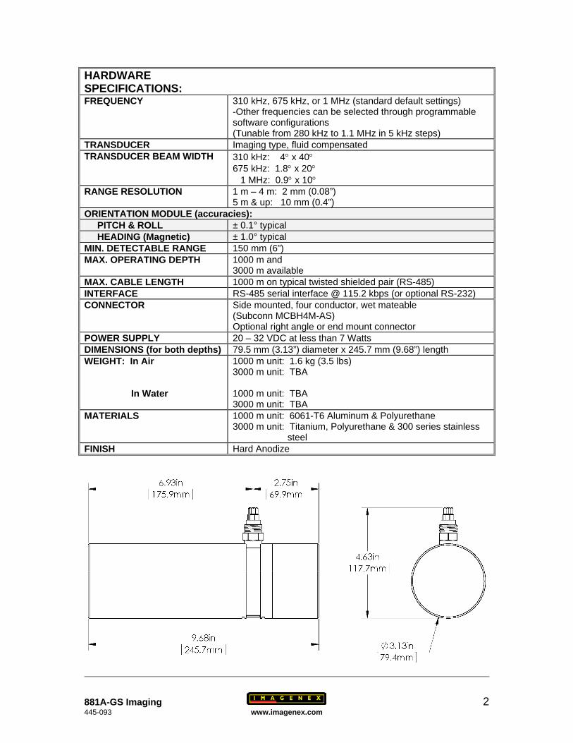
HARDWARE SPECIFICATIONS: FREQUENCY 310 kHz, 675 kHz, or 1 MHz (standard default settings)
-Other frequencies can be selected through programmable software configurations (Tunable from 280 kHz to 1.1 MHz in 5 kHz steps)
TRANSDUCER Imaging type, fluid compensated TRANSDUCER BEAM WIDTH 310 kHz: 4° x 40°
675 kHz: 1.8° x 20° 1 MHz: 0.9° x 10°
RANGE RESOLUTION 1 m – 4 m: 2 mm (0.08”) 5 m & up: 10 mm (0.4”)
ORIENTATION MODULE (accuracies): PITCH & ROLL ± 0.1° typical HEADING (Magnetic) ± 1.0° typical MIN. DETECTABLE RANGE 150 mm (6”) MAX. OPERATING DEPTH 1000 m and
3000 m available MAX. CABLE LENGTH 1000 m on typical twisted shielded pair (RS-485) INTERFACE RS-485 serial interface @ 115.2 kbps (or optional RS-232) CONNECTOR Side mounted, four conductor, wet mateable
(Subconn MCBH4M-AS) Optional right angle or end mount connector
POWER SUPPLY 20 – 32 VDC at less than 7 Watts DIMENSIONS (for both depths) 79.5 mm (3.13”) diameter x 245.7 mm (9.68”) length WEIGHT: In Air In Water
1000 m unit: 1.6 kg (3.5 lbs) 3000 m unit: TBA 1000 m unit: TBA 3000 m unit: TBA
MATERIALS 1000 m unit: 6061-T6 Aluminum & Polyurethane 3000 m unit: Titanium, Polyurethane & 300 series stainless steel
FINISH Hard Anodize
881A-GS Imaging 2 445-093 www.imagenex.com
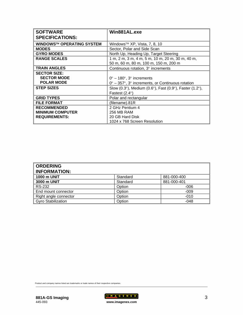
SOFTWARE SPECIFICATIONS:
Win881AL.exe
WINDOWS™ OPERATING SYSTEM Windows™ XP, Vista, 7, 8, 10 MODES Sector, Polar and Side Scan GYRO MODES North Up, Heading Up, Target Steering RANGE SCALES 1 m, 2 m, 3 m, 4 m, 5 m, 10 m, 20 m, 30 m, 40 m,
50 m, 60 m, 80 m, 100 m, 150 m, 200 m TRAIN ANGLES Continuous rotation, 3° increments SECTOR SIZE: SECTOR MODE POLAR MODE
0° – 180°, 3° increments 0° – 357°, 3° increments, or Continuous rotation
STEP SIZES Slow (0.3°), Medium (0.6°), Fast (0.9°), Faster (1.2°), Fastest (2.4°)
GRID TYPES Polar and rectangular FILE FORMAT (filename).81R RECOMMENDED MINIMUM COMPUTER REQUIREMENTS:
2 GHz Pentium 4 256 MB RAM 20 GB Hard Disk 1024 x 768 Screen Resolution
ORDERING INFORMATION: 1000 m UNIT Standard 881-000-400 3000 m UNIT Standard 881-000-401 RS-232 Option -006 End mount connector Option -009 Right angle connector Option -010 Gyro Stabilization Option -048
Product and company names listed are trademarks or trade names of their respective companies.
881A-GS Imaging 3 445-093 www.imagenex.com
IMAGENEX TECHNOLOGY CORP.
Model 881A-GS Gyro Stabilized Scanning Sonar
(Serial Version)
Quick Start
Number 430 - 031
Revision Date Description00 May 6, 2014 Release01 January 22, 2015 Software update02 July 6, 2015 Updated Gyro calibration description
Specifications subject to change without notice
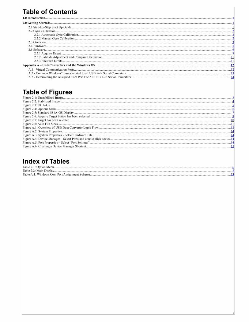
Table of Contents1.0 Introduction.....................................................................................................................................................................................................................................1
2.0 Getting Started:...............................................................................................................................................................................................................................12.1 Step-By-Step Start Up Guide.....................................................................................................................................................................................................12.2 Gyro Calibration.........................................................................................................................................................................................................................2
2.2.1 Automatic Gyro Calibration.............................................................................................................................................................................................22.2.2 Manual Gyro Calibration.................................................................................................................................................................................................2
2.3 Overview....................................................................................................................................................................................................................................32.4 Hardware....................................................................................................................................................................................................................................52.5 Software.....................................................................................................................................................................................................................................6
2.5.1 Acquire Target..................................................................................................................................................................................................................82.5.2 Latitude Adjustment and Compass Declination.............................................................................................................................................................112.5.3 File Size Limits..............................................................................................................................................................................................................11
Appendix A – USB Converters and the Windows OS......................................................................................................................................................................12A.1 - Virtual Communication Ports................................................................................................................................................................................................12A.2 - Common Windows© Issues related to all USB <--> Serial Converters................................................................................................................................13A.3 - Determining the Assigned Com Port For All USB <--> Serial Converters..........................................................................................................................14
Table of FiguresFigure 2.1: Unstabilized Image...............................................................................................................................................................................................................3Figure 2.2: Stabilized Image...................................................................................................................................................................................................................4Figure 2.3: 881A-GS...............................................................................................................................................................................................................................5Figure 2.4: Options Menu.......................................................................................................................................................................................................................6Figure 2.5: Standard 881A-GS Display..................................................................................................................................................................................................7Figure 2.6: Acquire Target button has been selected...............................................................................................................................................................................9Figure 2.7: Target has been selected......................................................................................................................................................................................................10Figure 2.8: Auto File Sizes....................................................................................................................................................................................................................11Figure A.1: Overview of USB Data Converter Logic Flow..................................................................................................................................................................12Figure A.2: System Properties...............................................................................................................................................................................................................14Figure A.3: System Properties - Select Hardware Tab..........................................................................................................................................................................14Figure A.4: Device Manager – Select Ports and double click device...................................................................................................................................................14Figure A.5: Port Properties – Select “Port Settings”.............................................................................................................................................................................14Figure A.6: Creating a Device Manager Shortcut.................................................................................................................................................................................15
Index of TablesTable 2.1: Option Menu...........................................................................................................................................................................................................................6Table 2.2: Main Display..........................................................................................................................................................................................................................8Table A.1: Windows Com Port Assignment Scheme............................................................................................................................................................................13
i
Model 881A-GS Setup Guide 1.0 Introduction
1.0 Introduction
The Model 881A-GS is an advanced gyro-stabilized, high-resolution scanning sonar system that has been designed to provide simple, reliable, and accurate representation of underwater images.
2.0 Getting Started:
The 881A-GS was designed to be user friendly and simple to set up in the field. It is generally recommended however to perform a preliminary setup before heading out into the field.
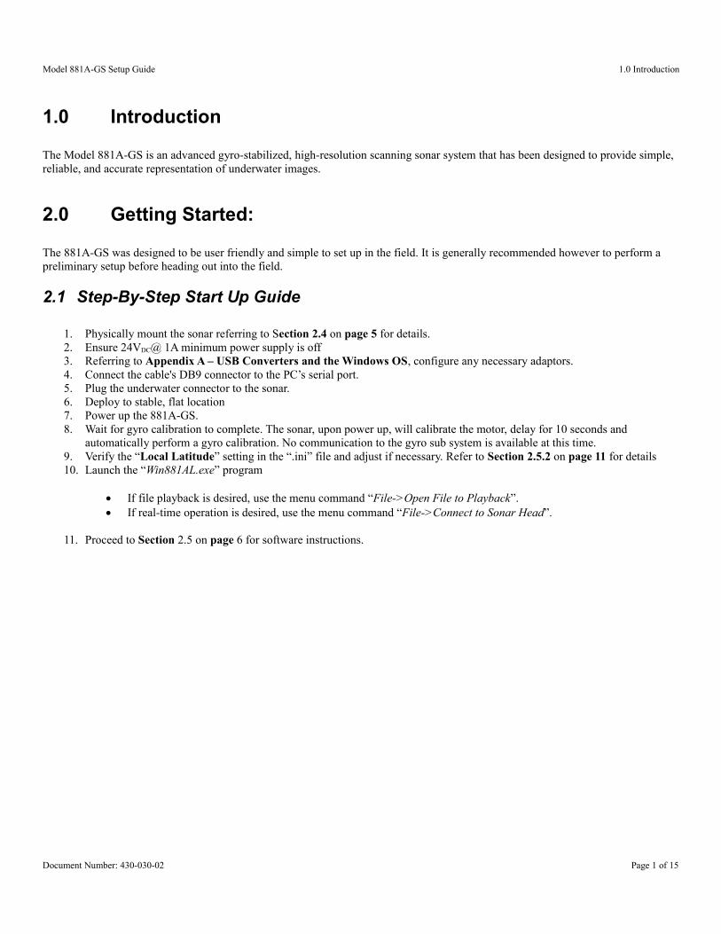
2.1 Step-By-Step Start Up Guide
1. Physically mount the sonar referring to Section 2.4 on page 5 for details.2. Ensure 24VDC@ 1A minimum power supply is off3. Referring to Appendix A – USB Converters and the Windows OS, configure any necessary adaptors.4. Connect the cable's DB9 connector to the PC’s serial port.5. Plug the underwater connector to the sonar.6. Deploy to stable, flat location7. Power up the 881A-GS.8. Wait for gyro calibration to complete. The sonar, upon power up, will calibrate the motor, delay for 10 seconds and
automatically perform a gyro calibration. No communication to the gyro sub system is available at this time.9. Verify the “Local Latitude” setting in the “.ini” file and adjust if necessary. Refer to Section 2.5.2 on page 11 for details10. Launch the “Win881AL.exe” program
If file playback is desired, use the menu command “File->Open File to Playback”. If real-time operation is desired, use the menu command “File->Connect to Sonar Head”.
11. Proceed to Section 2.5 on page 6 for software instructions.
Document Number: 430-030-02 Page 1 of 15
Model 881A-GS Setup Guide 2.2 Gyro Calibration
2.2 Gyro CalibrationAll gyros are sensitive to the environment (i.e. temperature, motion, Earth's rotation, etc.) and will naturally drift with time. Therefore,from time to time, it is recommended to issue a gyro calibration (in manual mode) or recalibrate the motor (auto mode) to remove the accumulated drift.
2.2.1 Automatic Gyro Calibration
Imagenex Gyro enabled scanning sonars now incorporate an automatic gyro biasing feature which is selectable in the user program. This mode continuously re-bias's the gyro in real time accommodating for temperature fluctuations and internal drift. Refer to Table 2.1 on page 6 for details on enabling / disabling this mode. When first starting the sonar, the bias adjustment will be very rapid as the temperature stabilizes. While the gyro will still internally drift, the sonar image will be coherent, allowing the operator to continue to work. Note that the absolute heading will not be exact during this time as the sonar does not differentiate between induced drift and real movement. After a few minutes, re-calibrate the motor to realign the sonar and the transducer. This will reset the accumulated driftthat occurred during the warmup period. It is recommended to periodically re-issue the calibrate motor command to reset the accumulated drift.
2.2.2 Manual Gyro Calibration
The information below describes the manual biasing mode which may be necessary in strong magnetic field environments. Do not calibrate the gyro until the internal temperature of the sonar has stabilized, approximately 30-60minutes underwater.
1. Mount sonar on a level, stable surface, or settle the ROV on a flat bottom.2. Under the “Options” Menu, select “Calibrate Gyro”.3. Standard sonar operation is suspended during gyro calibration.4. The message “Calibrating Gyro” will appear. Calibration takes approximately 30secs.5. Once the message disappears, standard operation commences.
When using MANUAL biasing, It is ESSENTIAL that the sonar is completely stationary and at constant temperature
during gyro calibration. ANY movement will cause undesirable drift in the gyro.
Document Number: 430-030-02 Page 2 of 15
Model 881A-GS Setup Guide 2.3 Overview
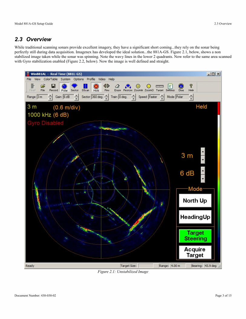
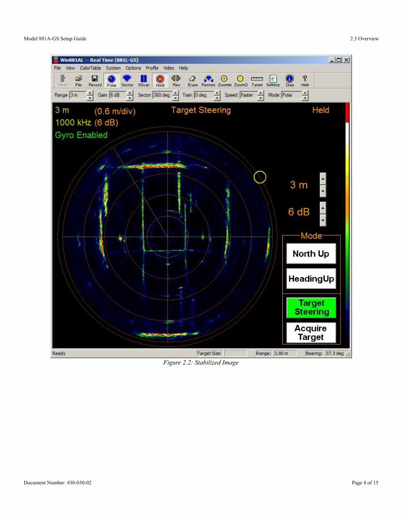
2.3 OverviewWhile traditional scanning sonars provide excellent imagery, they have a significant short coming...they rely on the sonar being perfectly still during data acquisition. Imagenex has developed the ideal solution...the 881A-GS. Figure 2.1, below, shows a non stabilized image taken while the sonar was spinning. Note the wavy lines in the lower 2 quadrants. Now refer to the same area scannedwith Gyro stabilization enabled (Figure 2.2, below). Now the image is well defined and straight.
Document Number: 430-030-02 Page 3 of 15
Figure 2.1: Unstabilized Image
Model 881A-GS Setup Guide 2.3 Overview
Document Number: 430-030-02 Page 4 of 15
Figure 2.2: Stabilized Image
Model 881A-GS Setup Guide 2.4 Hardware
2.4 Hardware
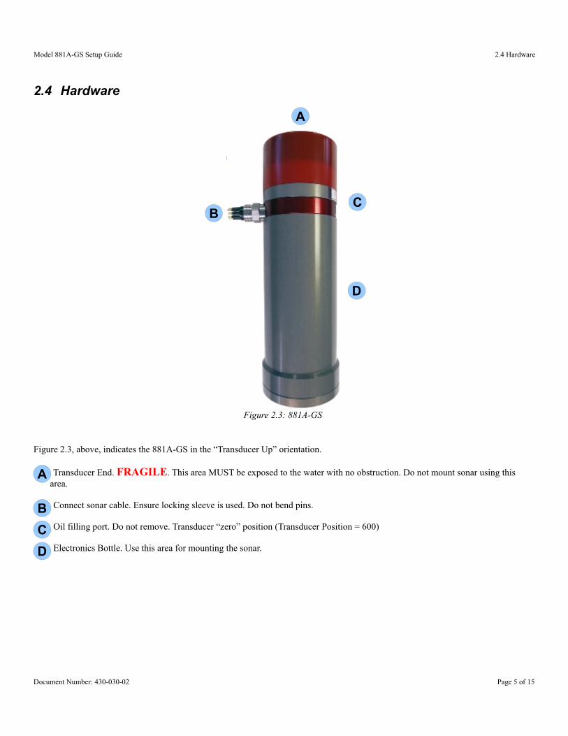
Figure 2.3: 881A-GS
Figure 2.3, above, indicates the 881A-GS in the “Transducer Up” orientation.
Transducer End. FRAGILE. This area MUST be exposed to the water with no obstruction. Do not mount sonar using this area.
Connect sonar cable. Ensure locking sleeve is used. Do not bend pins.
Oil filling port. Do not remove. Transducer “zero” position (Transducer Position = 600)
Electronics Bottle. Use this area for mounting the sonar.
Document Number: 430-030-02 Page 5 of 15
A
BC
D
A
B
C
D
A
Model 881A-GS Setup Guide 2.5 Software
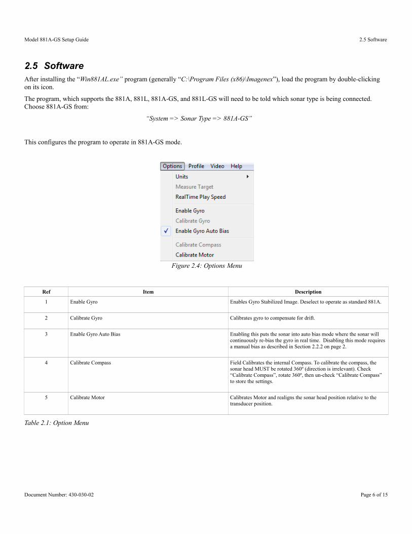
2.5 Software After installing the “Win881AL.exe” program (generally “C:\Program Files (x86)\Imagenex”), load the program by double-clicking on its icon.
The program, which supports the 881A, 881L, 881A-GS, and 881L-GS will need to be told which sonar type is being connected. Choose 881A-GS from:
“System => Sonar Type => 881A-GS”
This configures the program to operate in 881A-GS mode.
Figure 2.4: Options Menu
Ref Item Description
1 Enable Gyro Enables Gyro Stabilized Image. Deselect to operate as standard 881A.
2 Calibrate Gyro Calibrates gyro to compensate for drift.
3 Enable Gyro Auto Bias Enabling this puts the sonar into auto bias mode where the sonar will continuously re-bias the gyro in real time. Disabling this mode requiresa manual bias as described in Section 2.2.2 on page 2.
4 Calibrate Compass Field Calibrates the internal Compass. To calibrate the compass, the sonar head MUST be rotated 360º (direction is irrelevant). Check “Calibrate Compass”, rotate 360º, then un-check “Calibrate Compass” to store the settings.
5 Calibrate Motor Calibrates Motor and realigns the sonar head position relative to the transducer position.
Table 2.1: Option Menu
Document Number: 430-030-02 Page 6 of 15
Model 881A-GS Setup Guide 2.5 Software
Figure 2.5: Standard 881A-GS Display
Document Number: 430-030-02 Page 7 of 15
8
7
6 5
4
321
9
1
5
Model 881A-GS Setup Guide 2.5 Software
Ref Item Description
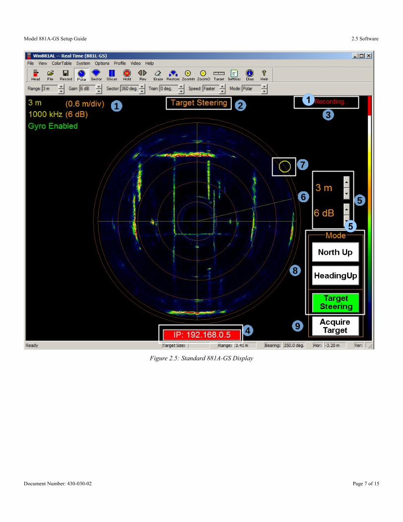
1 Range / Frequency Display Display current acoustic range and frequency of sonar in yellow. Displays Grid scale and current gain in orange
2 Gyro stabilized operating mode Displays only when Gyro Stabilized Image is enabled. One of: North Up, Heading Up, or Target Steering.
3 File Recording information Displays “Not Recording” or “Recording...”
4 Communication Error Status Displays “No Connection” when communication to the sonar is interrupted.
5 Quick Setting Quick Setting for sonar range and gain
6 Wiper Current transducer position for the “ping”
7 Sonar Position Indicator The yellow circle indicates the current sonar position independent of thetransducer position.
In North Up mode, the circle will transverse around the perimeter of thesonar image which remains stationary in a North up orientation.
In Heading Up mode, the circle will remain stationary at the top of the screen, while the sonar image rotates.
In Target Steering mode, the circle will transverse around the perimeter of the sonar image which remains stationary
8 Gyro Stabilized Image mode selection Selects the various modes of display.
In North Up mode, the circle will transverse around the perimeter of thesonar image which remains stationary in a North up orientation.
In Heading Up mode, the circle will remain stationary at the top of the screen, while the sonar image rotates according to the heading.
In Target Steering mode, the circle will transverse around the perimeter of the sonar image which remains stationary
9 Acquire Target Only active in “Target Steering mode, “Acquire Target” allow the user to select a target location. The sector will then be centred on the selected target and rotated to place the target at the top of the display. See Section 2.5.1, below for details.
Table 2.2: Main Display
2.5.1 Acquire Target
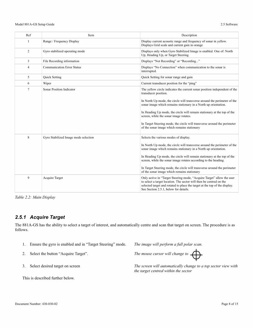
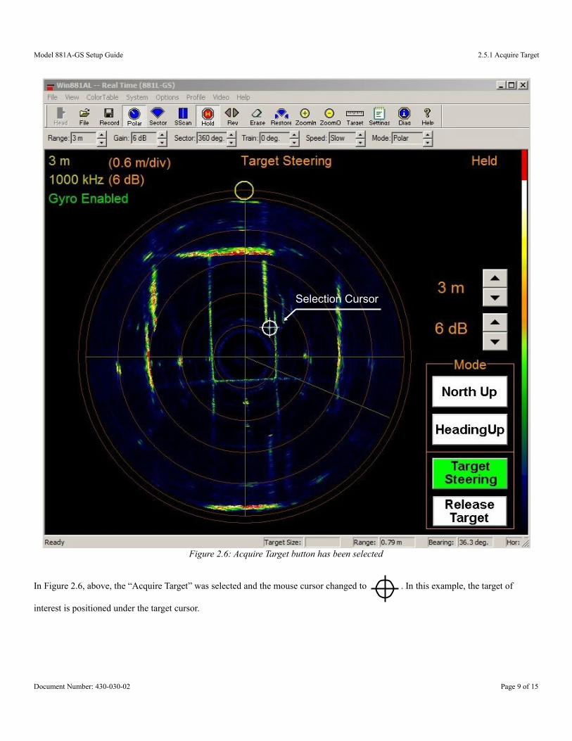
The 881A-GS has the ability to select a target of interest, and automatically centre and scan that target on screen. The procedure is as follows.
1. Ensure the gyro is enabled and in “Target Steering” mode. The image will perform a full polar scan.
2. Select the button “Acquire Target”. The mouse cursor will change to
3. Select desired target on screen The screen will automatically change to a top sector view withthe target centred within the sector
This is described further below.
Document Number: 430-030-02 Page 8 of 15
Model 881A-GS Setup Guide 2.5.1 Acquire Target
In Figure 2.6, above, the “Acquire Target” was selected and the mouse cursor changed to . In this example, the target of
interest is positioned under the target cursor.
Document Number: 430-030-02 Page 9 of 15
Figure 2.6: Acquire Target button has been selected
Selection Cursor
Model 881A-GS Setup Guide 2.5.1 Acquire Target
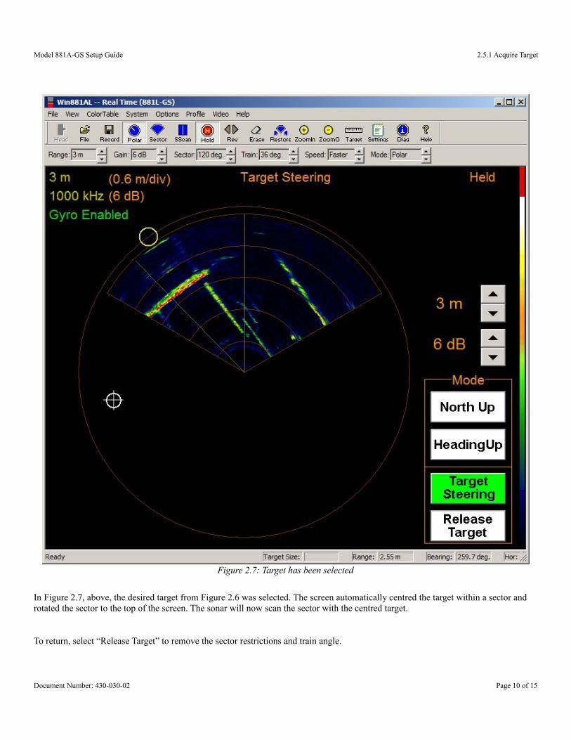
In Figure 2.7, above, the desired target from Figure 2.6 was selected. The screen automatically centred the target within a sector and rotated the sector to the top of the screen. The sonar will now scan the sector with the centred target.
To return, select “Release Target” to remove the sector restrictions and train angle.
Document Number: 430-030-02 Page 10 of 15
Figure 2.7: Target has been selected
Model 881A-GS Setup Guide 2.5.2 Latitude Adjustment and Compass Declination
2.5.2 Latitude Adjustment and Compass Declination
The geographical local latitude compensates for drift caused by the Earth's rotation. To set the latitude of the current location, open thefile “Win881AL.ini” in a text editor and edit the lines:
• Local Latitude=49.250000 → (0 to 90 for northern latitudes, 0 to -90 for southern latitudes)• CompassDeclination=16.5 → (±180º, offset to Magnetic North. West is negative, East is positive).
To match the approximate location of the sonar.Once these are set, run the “Win881AL.exe” program as per usual.
The “Local Latitude” will not take effect until a “CALIBRATE GYRO” command is initiatedmanually under the “Options” menu.
The compass declination angle is used for displaying the sonar image referenced to True North rather than Magnetic North.The default values are for Vancouver, BC, Canada which has a latitude of 49.25º North and a magnetic compass declination of 16.5º East (as of 2014).
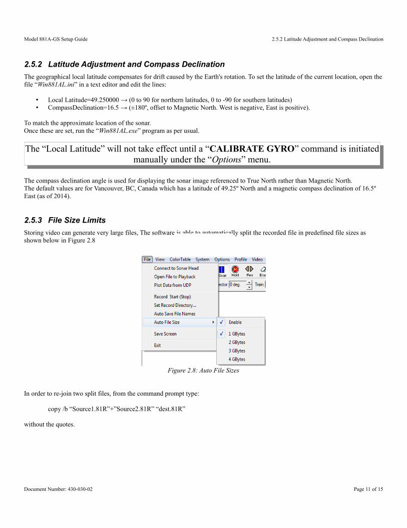
2.5.3 File Size Limits
Storing video can generate very large files, The software is able to automatically split the recorded file in predefined file sizes as shown below in Figure 2.8
Figure 2.8: Auto File Sizes
In order to re-join two split files, from the command prompt type:
copy /b “Source1.81R”+”Source2.81R” “dest.81R”
without the quotes.
Document Number: 430-030-02 Page 11 of 15
Model 881A-GS Setup Guide Appendix A – USB Converters and the Windows OS
Appendix A – USB Converters and the Windows OS
With the proliferation of the “Universal Serial Bus” (USB) compatible devices available for notebook and desktop computers, manufacturers are rapidly omitting physical serial ports on their products in order to cut production costs. The USB bus is extremely versatile as there are are no Com Port conflicts, no IRQ's to deal with, and has support for up to 256 devices on one bus(while there are usually multiple USB ports on a computer, there are usually only two physical USB buses).
With all that is going for it, one would wonder why use serial devices at all. Good question. Major factors in retaining a true physical serial device are:
● Cable length – USB has a maximum cable length support of 5m (~16')● Latency – USB is a packet driven technology and as such delays occur due to USB driver packaging schemes.
A.1 - Virtual Communication Ports
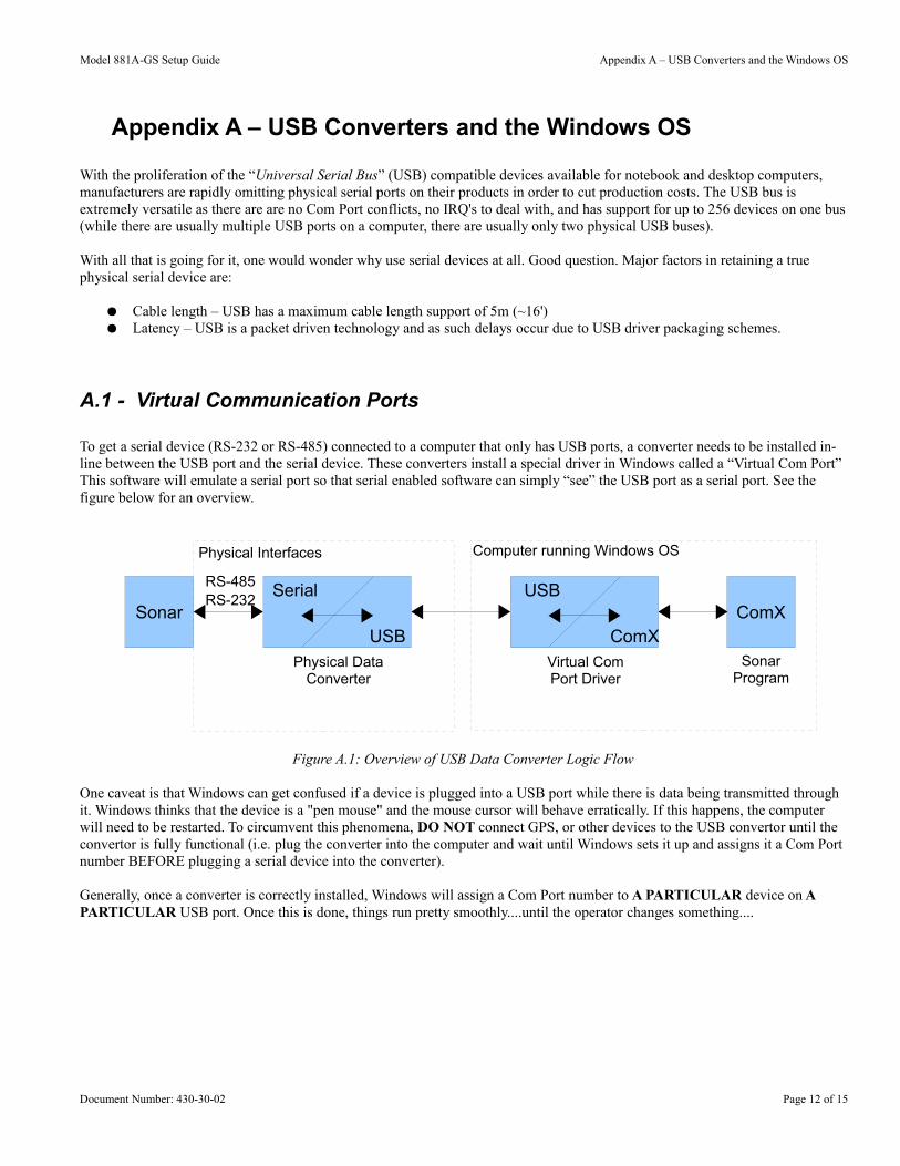
To get a serial device (RS-232 or RS-485) connected to a computer that only has USB ports, a converter needs to be installed in-line between the USB port and the serial device. These converters install a special driver in Windows called a “Virtual Com Port” This software will emulate a serial port so that serial enabled software can simply “see” the USB port as a serial port. See the figure below for an overview.
One caveat is that Windows can get confused if a device is plugged into a USB port while there is data being transmitted through it. Windows thinks that the device is a "pen mouse" and the mouse cursor will behave erratically. If this happens, the computer will need to be restarted. To circumvent this phenomena, DO NOT connect GPS, or other devices to the USB convertor until the convertor is fully functional (i.e. plug the converter into the computer and wait until Windows sets it up and assigns it a Com Port number BEFORE plugging a serial device into the converter).
Generally, once a converter is correctly installed, Windows will assign a Com Port number to A PARTICULAR device on A PARTICULAR USB port. Once this is done, things run pretty smoothly....until the operator changes something....
Document Number: 430-30-02 Page 12 of 15
Figure A.1: Overview of USB Data Converter Logic Flow
RS-232Sonar ComX
Physical Data Converter
Virtual ComPort Driver
RS-485Serial
USB
USB
ComXSonar
Program
Computer running Windows OSPhysical Interfaces
Model 881A-GS Setup Guide Appendix A – USB Converters and the Windows OS
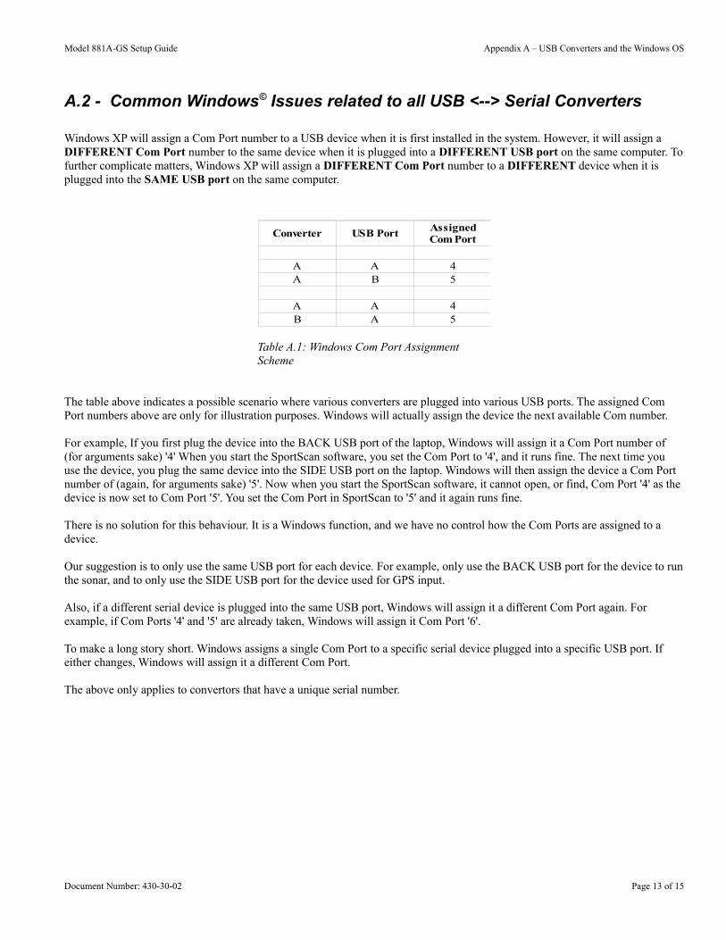
A.2 - Common Windows© Issues related to all USB <--> Serial Converters
Windows XP will assign a Com Port number to a USB device when it is first installed in the system. However, it will assign a DIFFERENT Com Port number to the same device when it is plugged into a DIFFERENT USB port on the same computer. Tofurther complicate matters, Windows XP will assign a DIFFERENT Com Port number to a DIFFERENT device when it is plugged into the SAME USB port on the same computer.
The table above indicates a possible scenario where various converters are plugged into various USB ports. The assigned Com Port numbers above are only for illustration purposes. Windows will actually assign the device the next available Com number.
For example, If you first plug the device into the BACK USB port of the laptop, Windows will assign it a Com Port number of (for arguments sake) '4' When you start the SportScan software, you set the Com Port to '4', and it runs fine. The next time you use the device, you plug the same device into the SIDE USB port on the laptop. Windows will then assign the device a Com Port number of (again, for arguments sake) '5'. Now when you start the SportScan software, it cannot open, or find, Com Port '4' as the device is now set to Com Port '5'. You set the Com Port in SportScan to '5' and it again runs fine.
There is no solution for this behaviour. It is a Windows function, and we have no control how the Com Ports are assigned to a device.
Our suggestion is to only use the same USB port for each device. For example, only use the BACK USB port for the device to runthe sonar, and to only use the SIDE USB port for the device used for GPS input.
Also, if a different serial device is plugged into the same USB port, Windows will assign it a different Com Port again. For example, if Com Ports '4' and '5' are already taken, Windows will assign it Com Port '6'.
To make a long story short. Windows assigns a single Com Port to a specific serial device plugged into a specific USB port. If either changes, Windows will assign it a different Com Port.
The above only applies to convertors that have a unique serial number.
Document Number: 430-30-02 Page 13 of 15
Table A.1: Windows Com Port Assignment Scheme
Converter USB Port
A A 4A B 5
A A 4B A 5
AssignedCom Port
Model 881A-GS Setup Guide Appendix A – USB Converters and the Windows OS
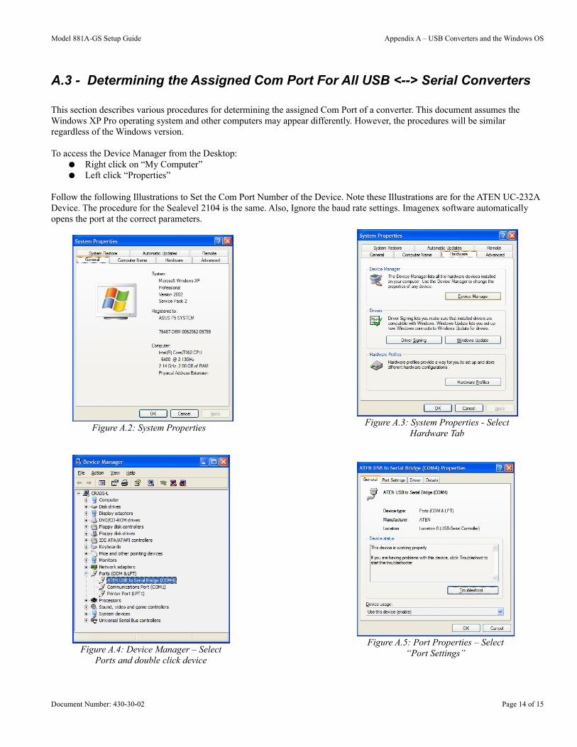
A.3 - Determining the Assigned Com Port For All USB <--> Serial Converters
This section describes various procedures for determining the assigned Com Port of a converter. This document assumes the Windows XP Pro operating system and other computers may appear differently. However, the procedures will be similar regardless of the Windows version.
To access the Device Manager from the Desktop:● Right click on “My Computer”● Left click “Properties”
Follow the following Illustrations to Set the Com Port Number of the Device. Note these Illustrations are for the ATEN UC-232A Device. The procedure for the Sealevel 2104 is the same. Also, Ignore the baud rate settings. Imagenex software automatically opens the port at the correct parameters.
Figure A.2: System Properties
Figure A.3: System Properties - SelectHardware Tab
Figure A.4: Device Manager – SelectPorts and double click device
Figure A.5: Port Properties – Select“Port Settings”
Document Number: 430-30-02 Page 14 of 15
Model 881A-GS Setup Guide Appendix A – USB Converters and the Windows OS
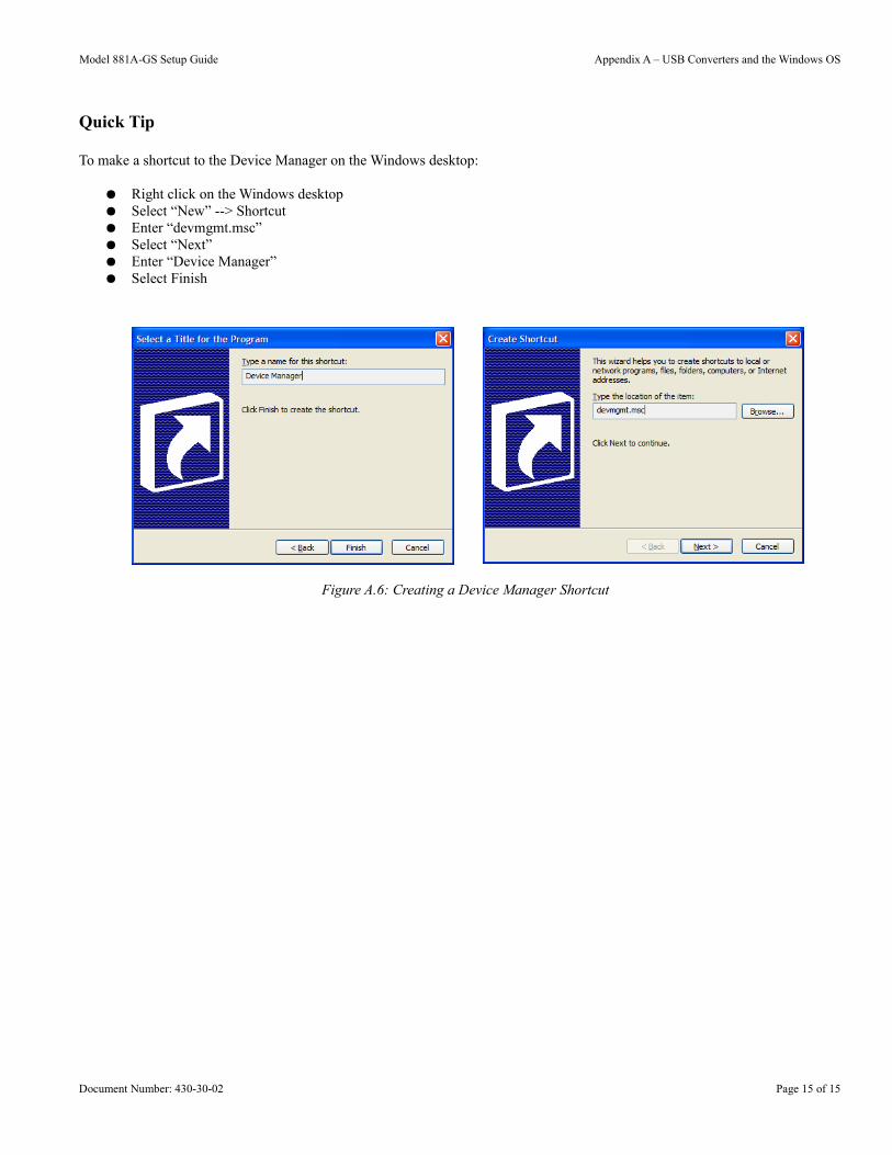
Quick Tip
To make a shortcut to the Device Manager on the Windows desktop:
● Right click on the Windows desktop● Select “New” --> Shortcut● Enter “devmgmt.msc”● Select “Next”● Enter “Device Manager”● Select Finish
Document Number: 430-30-02 Page 15 of 15
Figure A.6: Creating a Device Manager Shortcut
IMAGENEX TECHNOLOGY CORP. 13APR16
Imagenex 81R Raw Sonar Data File Format.doc Page 1 of 11
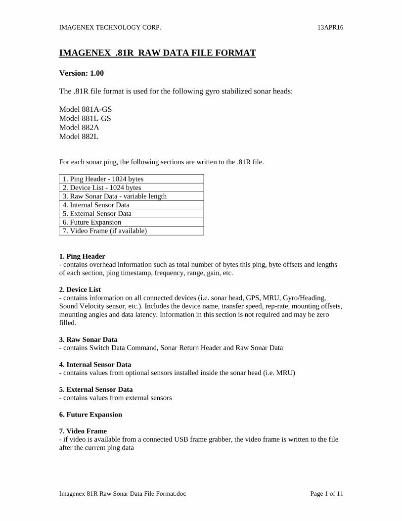
IMAGENEX .81R RAW DATA FILE FORMAT
Version: 1.00
The .81R file format is used for the following gyro stabilized sonar heads:
Model 881A-GS
Model 881L-GS
Model 882A
Model 882L
For each sonar ping, the following sections are written to the .81R file.
1. Ping Header - 1024 bytes
2. Device List - 1024 bytes
3. Raw Sonar Data - variable length
4. Internal Sensor Data
5. External Sensor Data
6. Future Expansion
7. Video Frame (if available)
1. Ping Header - contains overhead information such as total number of bytes this ping, byte offsets and lengths
of each section, ping timestamp, frequency, range, gain, etc.
2. Device List - contains information on all connected devices (i.e. sonar head, GPS, MRU, Gyro/Heading,
Sound Velocity sensor, etc.). Includes the device name, transfer speed, rep-rate, mounting offsets,
mounting angles and data latency. Information in this section is not required and may be zero
filled.
3. Raw Sonar Data - contains Switch Data Command, Sonar Return Header and Raw Sonar Data
4. Internal Sensor Data - contains values from optional sensors installed inside the sonar head (i.e. MRU)
5. External Sensor Data - contains values from external sensors
6. Future Expansion
7. Video Frame - if video is available from a connected USB frame grabber, the video frame is written to the file
after the current ping data
IMAGENEX TECHNOLOGY CORP. 13APR16
Imagenex 81R Raw Sonar Data File Format.doc Page 2 of 11
Storage Format
All data is stored LSB first (least significant byte first or "Little-Endian" mode). The following
conventions are used:
char 1-byte signed value
BYTE 1-byte unsigned value
ASCII 1-byte unsigned value
short 2-byte signed value (LSB,MSB)
WORD 2-byte unsigned value (LSB,MSB)
int 4-byte signed value (LSB,MDL,MDH,MSB)
DWORD 4-byte unsigned value (LSB,MDL,MDH,MSB)
float 4-byte single precision floating point value (LSB,MDL,MDH,MSB)
IMAGENEX TECHNOLOGY CORP. 13APR16
Imagenex 81R Raw Sonar Data File Format.doc Page 3 of 11
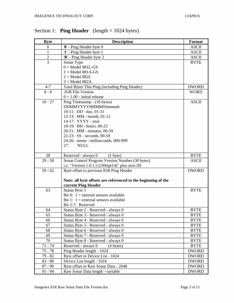
Section 1: Ping Header (length = 1024 bytes)
Byte Description Format
0 '8' - Ping Header byte 0 ASCII
1 '1' - Ping Header byte 1 ASCII
2 'R' - Ping Header byte 2 ASCII
3 Sonar Type
0 = Model 881L-GS
1 = Model 881A-GS
2 = Model 882L
3 = Model 882A
BYTE
4-7 Total Bytes This Ping (including Ping Header) DWORD
8 - 9 .81R File Version
0 = 1.00 - initial release
WORD
10 - 27 Ping Timestamp - (18 bytes)
DDMMYYYYHHMMSSmmmh
10-11: DD - day, 01-31
12-13: MM - month, 01-12
14-17: YYYY - year
18-19: HH - hours, 00-23
20-21: MM - minutes, 00-59
22-23: SS - seconds, 00-59
24-26: mmm - milliseconds, 000-999
27: NULL
ASCII
28 Reserved - always 0 (1 byte) BYTE
29 - 58 Sonar Control Program Version Number (30 bytes)
i.e. "Version 1.0.1.5 (19Sept14)" plus zero fill
ASCII
59 - 62 Byte offset to previous 81R Ping Header
Note: all byte offsets are referenced to the beginning of the
current Ping Header
DWORD
63 Status Byte 1
Bit 0: 1 = internal sensors available
Bit 1: 1 = external sensors available
Bit 2-7: Reserved
BYTE
64 Status Byte 2 - Reserved - always 0 BYTE
65 Status Byte 3 - Reserved - always 0 BYTE
66 Status Byte 4 - Reserved - always 0 BYTE
67 Status Byte 5 - Reserved - always 0 BYTE
68 Status Byte 6 - Reserved - always 0 BYTE
69 Status Byte 7 - Reserved - always 0 BYTE
70 Status Byte 8 - Reserved - always 0 BYTE
71 - 74 Reserved - always 0 (4 bytes) BYTE
75 - 78 Ping Header length - 1024 DWORD
79 - 82 Byte offset to Device List - 1024 DWORD
83 - 86 Device List length - 1024 DWORD
87 - 90 Byte offset to Raw Sonar Data - 2048 DWORD
91 - 94 Raw Sonar Data length - variable DWORD
IMAGENEX TECHNOLOGY CORP. 13APR16
Imagenex 81R Raw Sonar Data File Format.doc Page 4 of 11
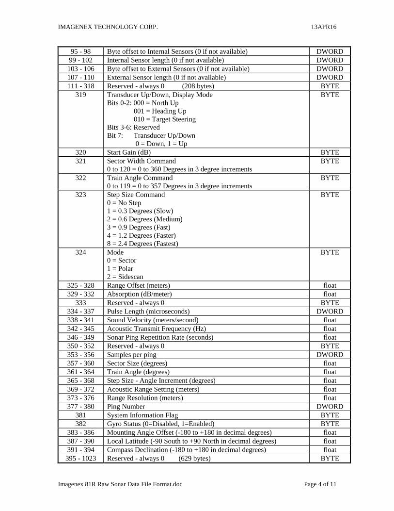
95 - 98 Byte offset to Internal Sensors (0 if not available) DWORD
99 - 102 Internal Sensor length (0 if not available) DWORD
103 - 106 Byte offset to External Sensors (0 if not available) DWORD
107 - 110 External Sensor length (0 if not available) DWORD
111 - 318 Reserved - always 0 (208 bytes) BYTE
319 Transducer Up/Down, Display Mode
Bits 0-2: 000 = North Up
001 = Heading Up
010 = Target Steering
Bits 3-6: Reserved
Bit 7: Transducer Up/Down
0 = Down, 1 = Up
BYTE
320 Start Gain (dB) BYTE
321 Sector Width Command
0 to 120 = 0 to 360 Degrees in 3 degree increments
BYTE
322 Train Angle Command
0 to 119 = 0 to 357 Degrees in 3 degree increments
BYTE
323 Step Size Command
0 = No Step
1 = 0.3 Degrees (Slow)
2 = 0.6 Degrees (Medium)
3 = 0.9 Degrees (Fast)
4 = 1.2 Degrees (Faster)
8 = 2.4 Degrees (Fastest)
BYTE
324 Mode
0 = Sector
1 = Polar
2 = Sidescan
BYTE
325 - 328 Range Offset (meters) float
329 - 332 Absorption (dB/meter) float
333 Reserved - always 0 BYTE
334 - 337 Pulse Length (microseconds) DWORD
338 - 341 Sound Velocity (meters/second) float
342 - 345 Acoustic Transmit Frequency (Hz) float
346 - 349 Sonar Ping Repetition Rate (seconds) float
350 - 352 Reserved - always 0 BYTE
353 - 356 Samples per ping DWORD
357 - 360 Sector Size (degrees) float
361 - 364 Train Angle (degrees) float
365 - 368 Step Size - Angle Increment (degrees) float
369 - 372 Acoustic Range Setting (meters) float
373 - 376 Range Resolution (meters) float
377 - 380 Ping Number DWORD
381 System Information Flag BYTE
382 Gyro Status (0=Disabled, 1=Enabled) BYTE
383 - 386 Mounting Angle Offset (-180 to +180 in decimal degrees) float
387 - 390 Local Latitude (-90 South to +90 North in decimal degrees) float
391 - 394 Compass Declination (-180 to +180 in decimal degrees) float
395 - 1023 Reserved - always 0 (629 bytes) BYTE
IMAGENEX TECHNOLOGY CORP. 13APR16
Imagenex 81R Raw Sonar Data File Format.doc Page 5 of 11
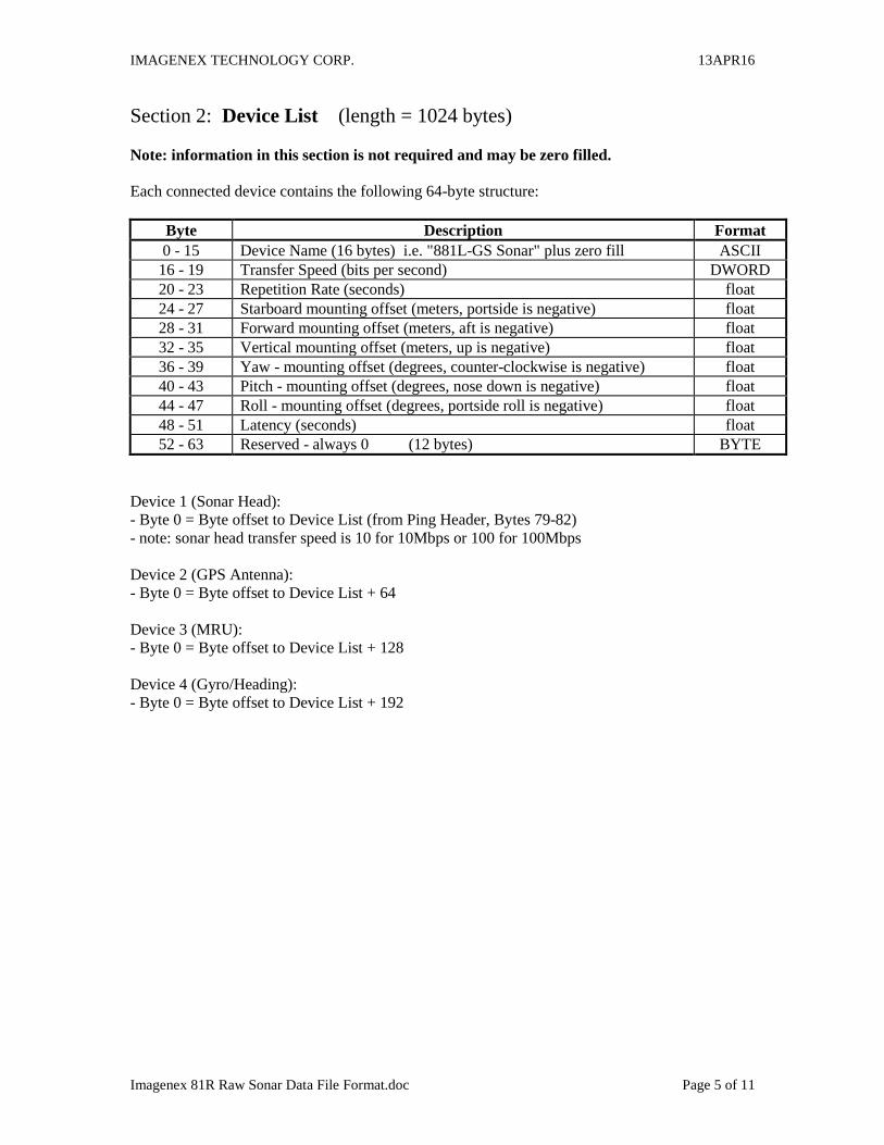
Section 2: Device List (length = 1024 bytes)
Note: information in this section is not required and may be zero filled.
Each connected device contains the following 64-byte structure:
Byte Description Format
0 - 15 Device Name (16 bytes) i.e. "881L-GS Sonar" plus zero fill ASCII
16 - 19 Transfer Speed (bits per second) DWORD
20 - 23 Repetition Rate (seconds) float
24 - 27 Starboard mounting offset (meters, portside is negative) float
28 - 31 Forward mounting offset (meters, aft is negative) float
32 - 35 Vertical mounting offset (meters, up is negative) float
36 - 39 Yaw - mounting offset (degrees, counter-clockwise is negative) float
40 - 43 Pitch - mounting offset (degrees, nose down is negative) float
44 - 47 Roll - mounting offset (degrees, portside roll is negative) float
48 - 51 Latency (seconds) float
52 - 63 Reserved - always 0 (12 bytes) BYTE
Device 1 (Sonar Head):
- Byte 0 = Byte offset to Device List (from Ping Header, Bytes 79-82)
- note: sonar head transfer speed is 10 for 10Mbps or 100 for 100Mbps
Device 2 (GPS Antenna):
- Byte 0 = Byte offset to Device List + 64
Device 3 (MRU):
- Byte 0 = Byte offset to Device List + 128
Device 4 (Gyro/Heading):
- Byte 0 = Byte offset to Device List + 192
IMAGENEX TECHNOLOGY CORP. 13APR16
Imagenex 81R Raw Sonar Data File Format.doc Page 6 of 11
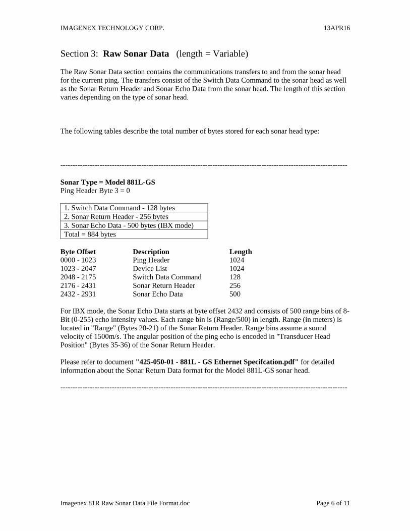
Section 3: Raw Sonar Data (length = Variable)
The Raw Sonar Data section contains the communications transfers to and from the sonar head
for the current ping. The transfers consist of the Switch Data Command to the sonar head as well
as the Sonar Return Header and Sonar Echo Data from the sonar head. The length of this section
varies depending on the type of sonar head.
The following tables describe the total number of bytes stored for each sonar head type:
---------------------------------------------------------------------------------------------------------------------
Sonar Type = Model 881L-GS
Ping Header Byte 3 = 0
1. Switch Data Command - 128 bytes
2. Sonar Return Header - 256 bytes
3. Sonar Echo Data - 500 bytes (IBX mode)
Total = 884 bytes
Byte Offset Description Length
0000 - 1023 Ping Header 1024
1023 - 2047 Device List 1024
2048 - 2175 Switch Data Command 128
2176 - 2431 Sonar Return Header 256
2432 - 2931 Sonar Echo Data 500
For IBX mode, the Sonar Echo Data starts at byte offset 2432 and consists of 500 range bins of 8-
Bit (0-255) echo intensity values. Each range bin is (Range/500) in length. Range (in meters) is
located in "Range" (Bytes 20-21) of the Sonar Return Header. Range bins assume a sound
velocity of 1500m/s. The angular position of the ping echo is encoded in "Transducer Head
Position" (Bytes 35-36) of the Sonar Return Header.
Please refer to document "425-050-01 - 881L - GS Ethernet Specifcation.pdf" for detailed
information about the Sonar Return Data format for the Model 881L-GS sonar head.
---------------------------------------------------------------------------------------------------------------------

IMAGENEX TECHNOLOGY CORP. 13APR16
Imagenex 81R Raw Sonar Data File Format.doc Page 7 of 11
---------------------------------------------------------------------------------------------------------------------
Sonar Type = Model 881A-GS
Ping Header Byte 3 = 1
1. Switch Data Command - 40 bytes
2. Sonar Return Header - 32 bytes
3. Sonar Echo Data - 500 bytes (INB mode)
Total = 572 bytes
Byte Offset Description Length
0000 - 1023 Ping Header 1024
1023 - 2047 Device List 1024
2048 - 2087 Switch Data Command 40
2088 - 2119 Sonar Return Header 32
2120 - 2619 Sonar Echo Data 500
For INB mode, the Sonar Echo Data starts at byte offset 2120 and consists of 500 range bins of 7-
Bit (0-127) echo intensity values. Each range bin is (Range/500) in length. Range (in meters) is
located in "Range" (Byte 7) of the Sonar Return Header. Range bins assume a sound velocity of
1500m/s. The angular position of the ping echo is encoded in "Transducer Head Position" (Bytes
5-6) of the Sonar Return Header.
Please refer to document "425-051-03 - 881A - gyro Serial Specifcation.pdf" for detailed
information about the Sonar Return Data format for the Model 881A-GS sonar head.
---------------------------------------------------------------------------------------------------------------------
IMAGENEX TECHNOLOGY CORP. 13APR16
Imagenex 81R Raw Sonar Data File Format.doc Page 8 of 11
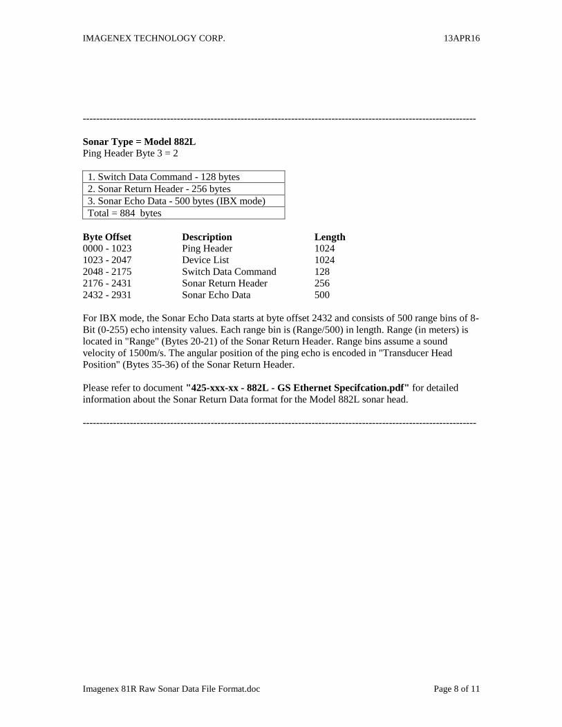
---------------------------------------------------------------------------------------------------------------------
Sonar Type = Model 882L
Ping Header Byte 3 = 2
1. Switch Data Command - 128 bytes
2. Sonar Return Header - 256 bytes
3. Sonar Echo Data - 500 bytes (IBX mode)
Total = 884 bytes
Byte Offset Description Length
0000 - 1023 Ping Header 1024
1023 - 2047 Device List 1024
2048 - 2175 Switch Data Command 128
2176 - 2431 Sonar Return Header 256
2432 - 2931 Sonar Echo Data 500
For IBX mode, the Sonar Echo Data starts at byte offset 2432 and consists of 500 range bins of 8-
Bit (0-255) echo intensity values. Each range bin is (Range/500) in length. Range (in meters) is
located in "Range" (Bytes 20-21) of the Sonar Return Header. Range bins assume a sound
velocity of 1500m/s. The angular position of the ping echo is encoded in "Transducer Head
Position" (Bytes 35-36) of the Sonar Return Header.
Please refer to document "425-xxx-xx - 882L - GS Ethernet Specifcation.pdf" for detailed
information about the Sonar Return Data format for the Model 882L sonar head.
---------------------------------------------------------------------------------------------------------------------
IMAGENEX TECHNOLOGY CORP. 13APR16
Imagenex 81R Raw Sonar Data File Format.doc Page 9 of 11
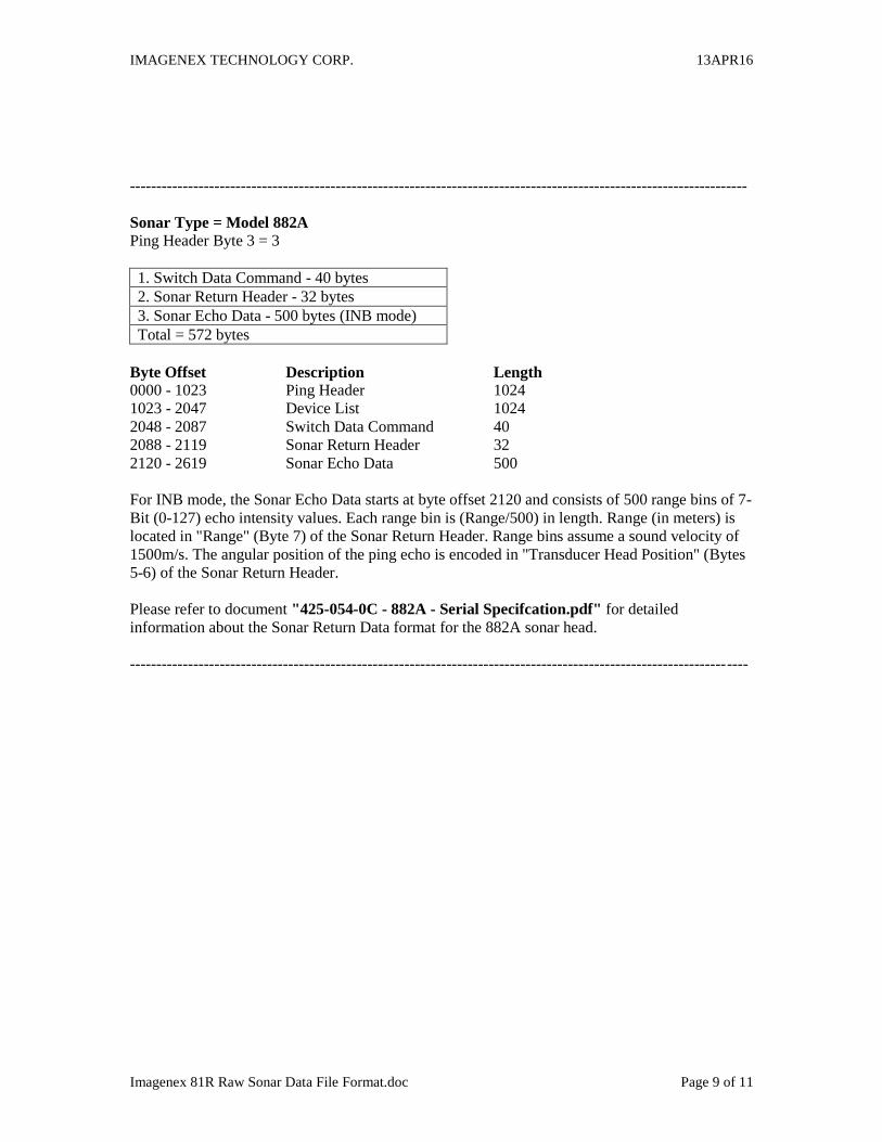
---------------------------------------------------------------------------------------------------------------------
Sonar Type = Model 882A
Ping Header Byte 3 = 3
1. Switch Data Command - 40 bytes
2. Sonar Return Header - 32 bytes
3. Sonar Echo Data - 500 bytes (INB mode)
Total = 572 bytes
Byte Offset Description Length
0000 - 1023 Ping Header 1024
1023 - 2047 Device List 1024
2048 - 2087 Switch Data Command 40
2088 - 2119 Sonar Return Header 32
2120 - 2619 Sonar Echo Data 500
For INB mode, the Sonar Echo Data starts at byte offset 2120 and consists of 500 range bins of 7-
Bit (0-127) echo intensity values. Each range bin is (Range/500) in length. Range (in meters) is
located in "Range" (Byte 7) of the Sonar Return Header. Range bins assume a sound velocity of
1500m/s. The angular position of the ping echo is encoded in "Transducer Head Position" (Bytes
5-6) of the Sonar Return Header.
Please refer to document "425-054-0C - 882A - Serial Specifcation.pdf" for detailed
information about the Sonar Return Data format for the 882A sonar head.
---------------------------------------------------------------------------------------------------------------------
IMAGENEX TECHNOLOGY CORP. 13APR16
Imagenex 81R Raw Sonar Data File Format.doc Page 10 of 11
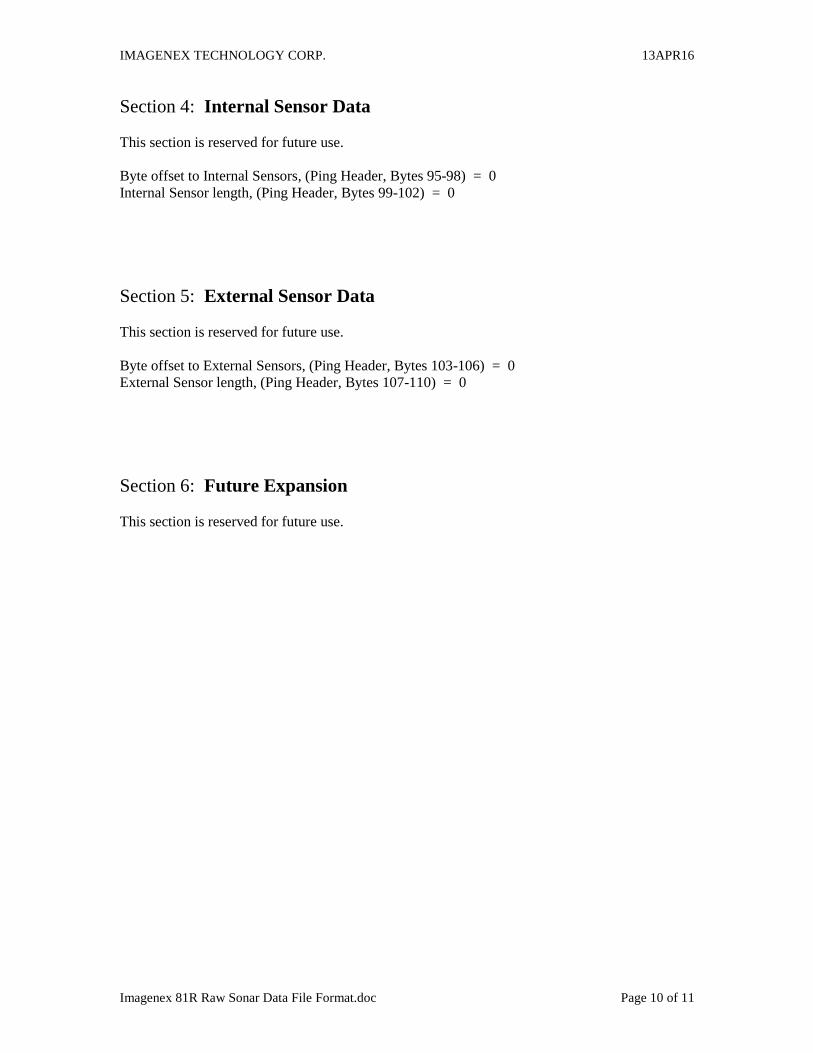
Section 4: Internal Sensor Data
This section is reserved for future use.
Byte offset to Internal Sensors, (Ping Header, Bytes 95-98) = 0
Internal Sensor length, (Ping Header, Bytes 99-102) = 0
Section 5: External Sensor Data
This section is reserved for future use.
Byte offset to External Sensors, (Ping Header, Bytes 103-106) = 0
External Sensor length, (Ping Header, Bytes 107-110) = 0
Section 6: Future Expansion
This section is reserved for future use.
IMAGENEX TECHNOLOGY CORP. 13APR16
Imagenex 81R Raw Sonar Data File Format.doc Page 11 of 11
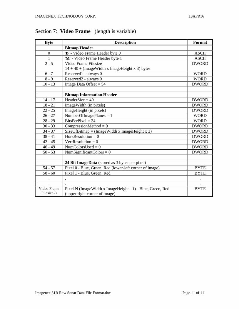
Section 7: Video Frame (length is variable)
Byte Description Format
Bitmap Header
0 'B' - Video Frame Header byte 0 ASCII
1 'M' - Video Frame Header byte 1 ASCII
2 - 5 Video Frame Filesize
14 + 40 + (ImageWidth x ImageHeight x 3) bytes
DWORD
6 - 7 Reserved1 - always 0 WORD
8 - 9 Reserved2 - always 0 WORD
10 - 13 Image Data Offset = 54 DWORD
Bitmap Information Header
14 - 17 HeaderSize = 40 DWORD
18 - 21 ImageWidth (in pixels) DWORD
22 - 25 ImageHeight (in pixels) DWORD
26 - 27 NumberOfImagePlanes = 1 WORD
28 - 29 BitsPerPixel = 24 WORD
30 - 33 CompressionMethod = 0 DWORD
34 - 37 SizeOfBitmap = (ImageWidth x ImageHeight x 3) DWORD
38 - 41 HorzResolution = 0 DWORD
42 - 45 VertResolution = 0 DWORD
46 - 49 NumColorsUsed = 0 DWORD
50 - 53 NumSignificantColors = 0 DWORD
24 Bit ImageData (stored as 3 bytes per pixel)
54 - 57 Pixel 0 - Blue, Green, Red (lower-left corner of image) BYTE
58 - 60 Pixel 1 - Blue, Green, Red BYTE
. . .
. . . Video Frame
Filesize-3 Pixel N (ImageWidth x ImageHeight - 1) - Blue, Green, Red
(upper-right corner of image)
BYTE

Imagenex Technology Corp.
IMAGENEX MODEL 881A-GS
with GYRO STABLIZED Option
MULTI-FREQUENCY SCANNING DIGITAL SONAR HEADImager / Profiler
SERIAL INTERFACESPECIFICATION
Version 2.0
Document Number 425-051
Revision Date Description
0A March 31, 2014 New Format0B April 22, 2014 Updates00 May 1, 2014 Initial Release01 July 21, 2014 Added variable gyro biasing time02 September 5, 2014 Added Compass calibrating status03 November 25, 2014 Adds motion tolerent gyro biasing, gyro compass
Specifications subject to change
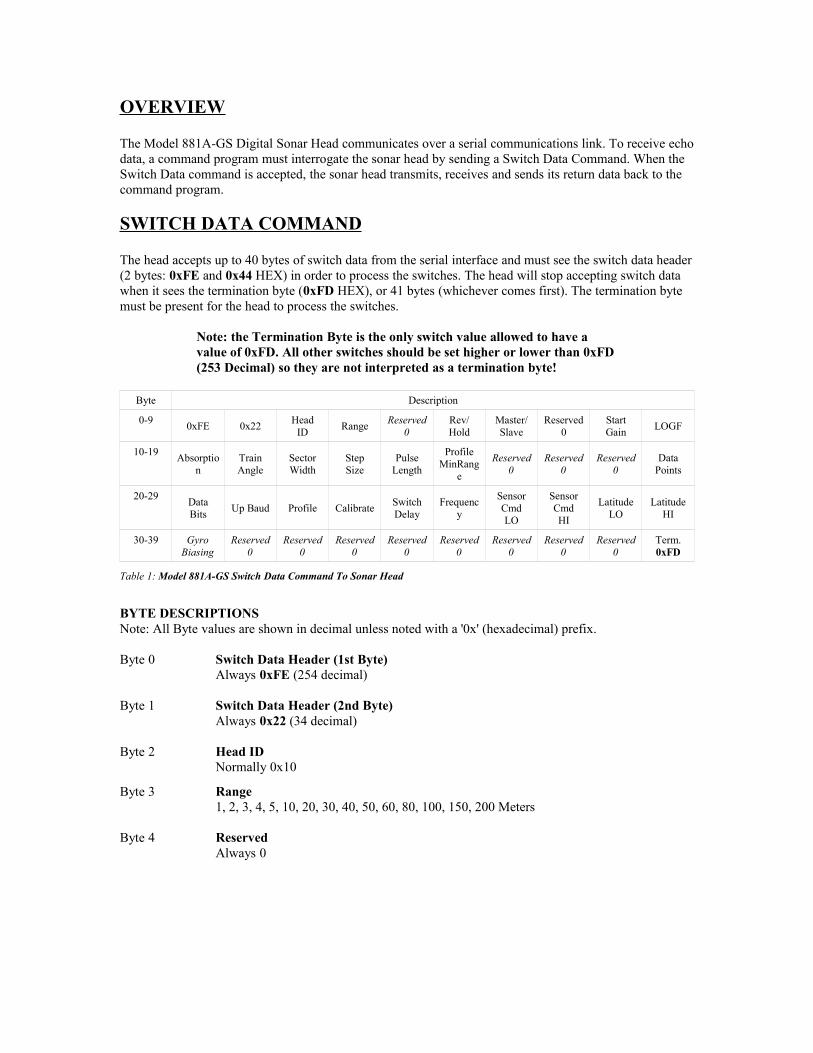
OVERVIEW
The Model 881A-GS Digital Sonar Head communicates over a serial communications link. To receive echodata, a command program must interrogate the sonar head by sending a Switch Data Command. When the Switch Data command is accepted, the sonar head transmits, receives and sends its return data back to the command program.
SWITCH DATA COMMAND
The head accepts up to 40 bytes of switch data from the serial interface and must see the switch data header(2 bytes: 0xFE and 0x44 HEX) in order to process the switches. The head will stop accepting switch data when it sees the termination byte (0xFD HEX), or 41 bytes (whichever comes first). The termination byte must be present for the head to process the switches.
Note: the Termination Byte is the only switch value allowed to have a value of 0xFD. All other switches should be set higher or lower than 0xFD(253 Decimal) so they are not interpreted as a termination byte!
Byte Description
0-90xFE 0x22
HeadID
RangeReserved
0Rev/Hold
Master/Slave
Reserved0
StartGain
LOGF
10-19Absorptio
nTrainAngle
SectorWidth
StepSize
PulseLength
ProfileMinRang
e
Reserved0
Reserved0
Reserved0
DataPoints
20-29DataBits
Up Baud Profile CalibrateSwitchDelay
Frequency
SensorCmdLO
SensorCmdHI
LatitudeLO
LatitudeHI
30-39 GyroBiasing
Reserved0
Reserved0
Reserved0
Reserved0
Reserved0
Reserved0
Reserved0
Reserved0
Term.0xFD
Table 1: Model 881A-GS Switch Data Command To Sonar Head
BYTE DESCRIPTIONSNote: All Byte values are shown in decimal unless noted with a '0x' (hexadecimal) prefix.
Byte 0 Switch Data Header (1st Byte)Always 0xFE (254 decimal)
Byte 1 Switch Data Header (2nd Byte)Always 0x22 (34 decimal)
Byte 2 Head IDNormally 0x10
Byte 3 Range1, 2, 3, 4, 5, 10, 20, 30, 40, 50, 60, 80, 100, 150, 200 Meters
Byte 4 ReservedAlways 0
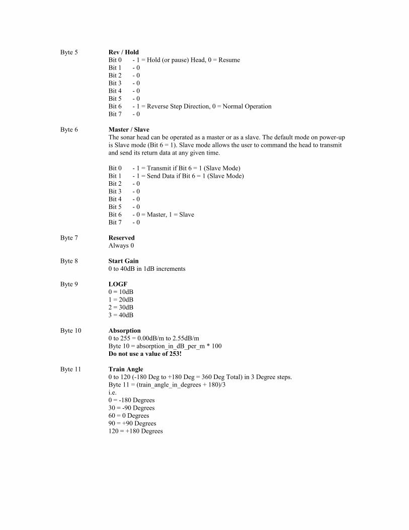
Byte 5 Rev / HoldBit 0 - 1 = Hold (or pause) Head, 0 = ResumeBit 1 - 0Bit 2 - 0Bit 3 - 0Bit 4 - 0Bit 5 - 0Bit 6 - 1 = Reverse Step Direction, 0 = Normal OperationBit 7 - 0
Byte 6 Master / SlaveThe sonar head can be operated as a master or as a slave. The default mode on power-up is Slave mode (Bit 6 = 1). Slave mode allows the user to command the head to transmit and send its return data at any given time.
Bit 0 - 1 = Transmit if Bit 6 = 1 (Slave Mode)Bit 1 - 1 = Send Data if Bit 6 = 1 (Slave Mode)Bit 2 - 0Bit 3 - 0Bit 4 - 0Bit 5 - 0Bit 6 - 0 = Master, 1 = SlaveBit 7 - 0
Byte 7 ReservedAlways 0
Byte 8 Start Gain0 to 40dB in 1dB increments
Byte 9 LOGF0 = 10dB1 = 20dB2 = 30dB3 = 40dB
Byte 10 Absorption0 to 255 = 0.00dB/m to 2.55dB/mByte 10 = absorption_in_dB_per_m * 100Do not use a value of 253!
Byte 11 Train Angle0 to 120 (-180 Deg to +180 Deg = 360 Deg Total) in 3 Degree steps.Byte 11 = (train_angle_in_degrees + 180)/3i.e.0 = -180 Degrees30 = -90 Degrees60 = 0 Degrees90 = +90 Degrees120 = +180 Degrees
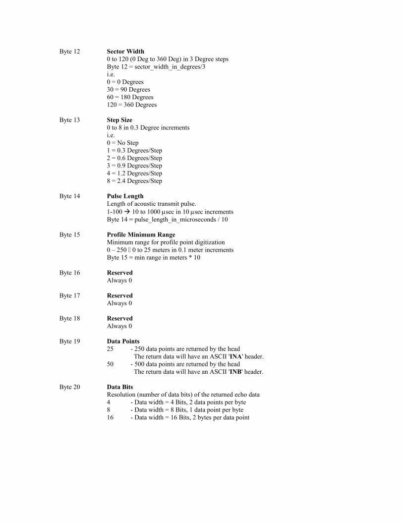
Byte 12 Sector Width0 to 120 (0 Deg to 360 Deg) in 3 Degree stepsByte 12 = sector_width_in_degrees/3i.e.0 = 0 Degrees30 = 90 Degrees60 = 180 Degrees120 = 360 Degrees
Byte 13 Step Size0 to 8 in 0.3 Degree incrementsi.e.0 = No Step1 = 0.3 Degrees/Step2 = 0.6 Degrees/Step3 = 0.9 Degrees/Step4 = 1.2 Degrees/Step8 = 2.4 Degrees/Step
Byte 14 Pulse LengthLength of acoustic transmit pulse.1-100 10 to 1000 msec in 10 msec incrementsByte 14 = pulse_length_in_microseconds / 10
Byte 15 Profile Minimum RangeMinimum range for profile point digitization0 – 250 0 to 25 meters in 0.1 meter incrementsByte 15 = min range in meters * 10
Byte 16 ReservedAlways 0
Byte 17 ReservedAlways 0
Byte 18 ReservedAlways 0
Byte 19 Data Points25 - 250 data points are returned by the head
The return data will have an ASCII 'INA' header.50 - 500 data points are returned by the head
The return data will have an ASCII 'INB' header.
Byte 20 Data BitsResolution (number of data bits) of the returned echo data4 - Data width = 4 Bits, 2 data points per byte8 - Data width = 8 Bits, 1 data point per byte16 - Data width = 16 Bits, 2 bytes per data point
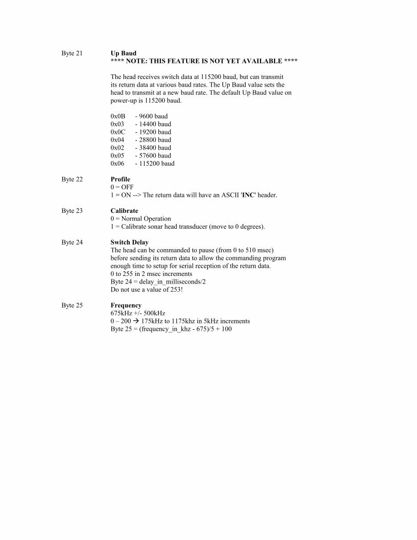
Byte 21 Up Baud**** NOTE: THIS FEATURE IS NOT YET AVAILABLE ****
The head receives switch data at 115200 baud, but can transmitits return data at various baud rates. The Up Baud value sets thehead to transmit at a new baud rate. The default Up Baud value onpower-up is 115200 baud.
0x0B - 9600 baud0x03 - 14400 baud0x0C - 19200 baud0x04 - 28800 baud0x02 - 38400 baud0x05 - 57600 baud0x06 - 115200 baud
Byte 22 Profile0 = OFF1 = ON --> The return data will have an ASCII 'INC' header.
Byte 23 Calibrate0 = Normal Operation1 = Calibrate sonar head transducer (move to 0 degrees).
Byte 24 Switch DelayThe head can be commanded to pause (from 0 to 510 msec)before sending its return data to allow the commanding programenough time to setup for serial reception of the return data.0 to 255 in 2 msec incrementsByte 24 = delay_in_milliseconds/2Do not use a value of 253!
Byte 25 Frequency675kHz +/- 500kHz0 – 200 175kHz to 1175khz in 5kHz incrementsByte 25 = (frequency_in_khz - 675)/5 + 100
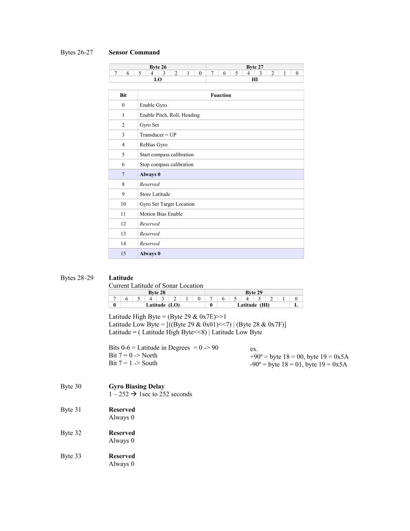
Bytes 26-27 Sensor Command
Byte 26 Byte 277 6 5 4 3 2 1 0 7 6 5 4 3 2 1 0
LO HI
Bit Function
0 Enable Gyro
1 Enable Pitch, Roll, Heading
2 Gyro Set
3 Transducer = UP
4 ReBias Gyro
5 Start compass calibration
6 Stop compass calibration
7 Always 0
8 Reserved
9 Store Latitude
10 Gyro Set Target Location
11 Motion Bias Enable
12 Reserved
13 Reserved
14 Reserved
15 Always 0
Bytes 28-29 LatitudeCurrent Latitude of Sonar Location
Byte 28 Byte 297 6 5 4 3 2 1 0 7 6 5 4 3 2 1 00 Latitude (LO) 0 Latitude (HI) L
Latitude High Byte = (Byte 29 & 0x7E)>>1 Latitude Low Byte = [((Byte 29 & 0x01)<<7) | (Byte 28 & 0x7F)] Latitude = ( Latitude High Byte<<8) | Latitude Low Byte
Bits 0-6 = Latitude in Degrees = 0 -> 90Bit 7 = 0 -> NorthBit 7 = 1 -> South
Byte 30 Gyro Biasing Delay1 – 252 1sec to 252 seconds
Byte 31 ReservedAlways 0
Byte 32 ReservedAlways 0
Byte 33 ReservedAlways 0
ex. +90º = byte 18 = 00, byte 19 = 0x5A -90º = byte 18 = 01, byte 19 = 0x5A
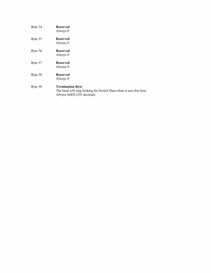
Byte 34 ReservedAlways 0
Byte 35 ReservedAlways 0
Byte 36 ReservedAlways 0
Byte 37 ReservedAlways 0
Byte 38 ReservedAlways 0
Byte 39 Termination ByteThe head will stop looking for Switch Data when it sees this byte.Always 0xFD (253 decimal)
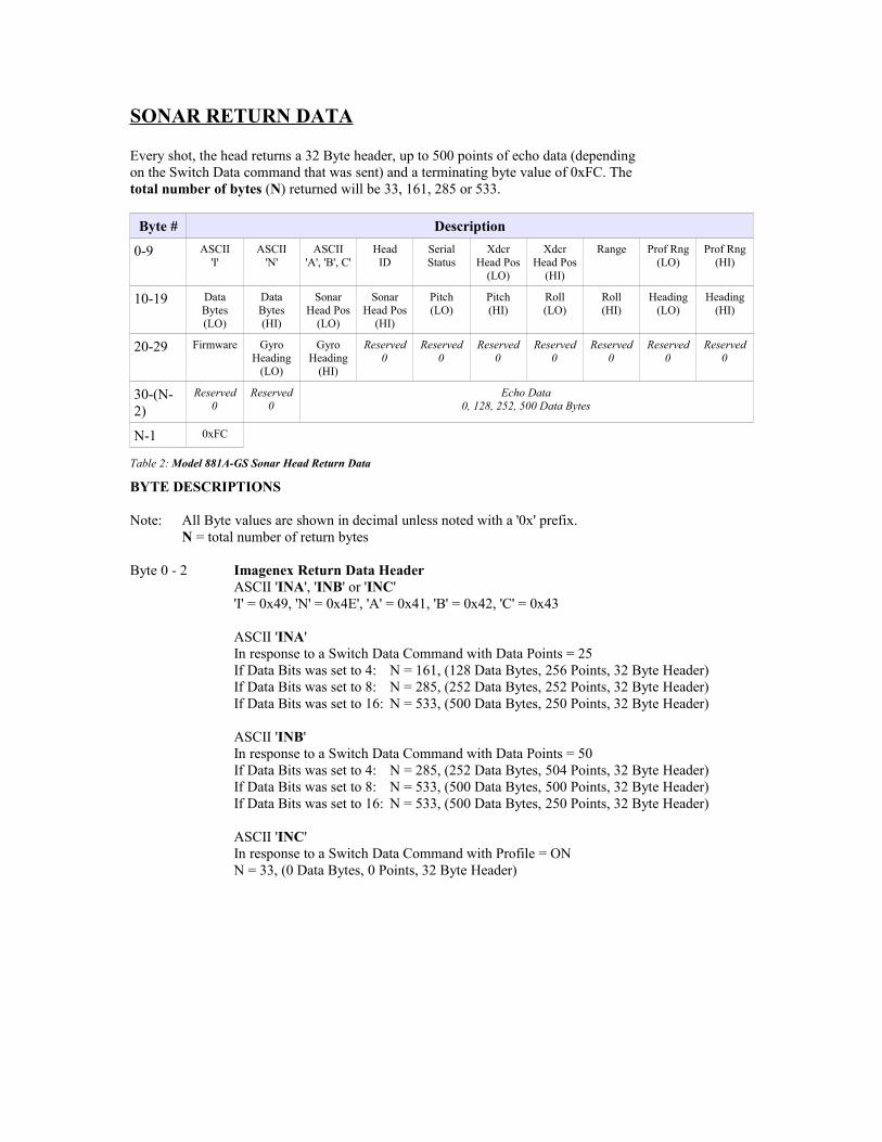
SONAR RETURN DATA
Every shot, the head returns a 32 Byte header, up to 500 points of echo data (dependingon the Switch Data command that was sent) and a terminating byte value of 0xFC. Thetotal number of bytes (N) returned will be 33, 161, 285 or 533.
Byte # Description
0-9 ASCII'I'
ASCII'N'
ASCII'A', 'B', C'
HeadID
SerialStatus
XdcrHead Pos
(LO)
XdcrHead Pos
(HI)
Range Prof Rng(LO)
Prof Rng(HI)
10-19 DataBytes(LO)
DataBytes(HI)
SonarHead Pos
(LO)
SonarHead Pos
(HI)
Pitch(LO)
Pitch(HI)
Roll(LO)
Roll(HI)
Heading(LO)
Heading(HI)
20-29 Firmware GyroHeading
(LO)
GyroHeading
(HI)
Reserved0
Reserved0
Reserved0
Reserved0
Reserved0
Reserved0
Reserved0
30-(N-2)
Reserved0
Reserved0
Echo Data0, 128, 252, 500 Data Bytes
N-1 0xFC
Table 2: Model 881A-GS Sonar Head Return Data
BYTE DESCRIPTIONS
Note: All Byte values are shown in decimal unless noted with a '0x' prefix.N = total number of return bytes
Byte 0 - 2 Imagenex Return Data HeaderASCII 'INA', 'INB' or 'INC''I' = 0x49, 'N' = 0x4E', 'A' = 0x41, 'B' = 0x42, 'C' = 0x43
ASCII 'INA'In response to a Switch Data Command with Data Points = 25If Data Bits was set to 4: N = 161, (128 Data Bytes, 256 Points, 32 Byte Header)If Data Bits was set to 8: N = 285, (252 Data Bytes, 252 Points, 32 Byte Header)If Data Bits was set to 16: N = 533, (500 Data Bytes, 250 Points, 32 Byte Header)
ASCII 'INB'In response to a Switch Data Command with Data Points = 50If Data Bits was set to 4: N = 285, (252 Data Bytes, 504 Points, 32 Byte Header)If Data Bits was set to 8: N = 533, (500 Data Bytes, 500 Points, 32 Byte Header)If Data Bits was set to 16: N = 533, (500 Data Bytes, 250 Points, 32 Byte Header)
ASCII 'INC'In response to a Switch Data Command with Profile = ONN = 33, (0 Data Bytes, 0 Points, 32 Byte Header)
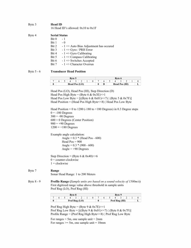
Byte 3 Head ID16 Head ID’s allowed: 0x10 to 0x1F
Byte 4 Serial StatusBit 0 - 1 Bit 1 - 0Bit 2 - 1 => Auto Bias Adjustment has occuredBit 3 - 1 => Gyro / PRH ErrorBit 4 - 1 => Gyro CalibratingBit 5 - 1 => Compass Calibrating Bit 6 - 1 => Switches AcceptedBit 7 - 1 => Character Overrun
Byte 5 - 6 Transducer Head Position
Byte 5 Byte 67 6 5 4 3 2 1 0 7 6 5 4 3 2 1 00 Head Pos (LO) 0 D Head Pos (HI) L
Head Pos (LO), Head Pos (HI), Step Direction (D)Head Pos High Byte = (Byte 6 & 0x3E)>>1Head Pos Low Byte = [((Byte 6 & 0x01)<<7) | (Byte 5 & 0x7F)]Head Position = (Head Pos High Byte<<8) | Head Pos Low Byte
Head Position = 0 to 1200 (-180 to +180 Degrees) in 0.3 Degree steps0 = -180 Degrees300 = -90 Degrees600 = 0 Degrees (Center Position)900 = +90 Degrees1200 = +180 Degrees
Example angle calculation:Angle = 0.3 * (Head Pos - 600)Head Pos = 900Angle = 0.3 * (900 - 600)Angle = +90 Degrees
Step Direction = (Byte 6 & 0x40)>>60 = counter-clockwise1 = clockwise
Byte 7 RangeSonar Head Range: 1 to 200 Meters
Byte 8 - 9 Profile Range (Sample units are based on a sound velocity of 1500m/s)First digitized range value above threshold in sample unitsProf Rng (LO), Prof Rng (HI)
Byte 8 Byte 97 6 5 4 3 2 1 0 7 6 5 4 3 2 1 00 Prof Rng (LO) 0 Prof Rng (HI) L
Prof Rng High Byte = (Byte 9 & 0x7E)>>1Prof Rng Low Byte = [((Byte 9 & 0x01)<<7) | (Byte 8 & 0x7F)]Profile Range = (Prof Rng High Byte<<8) | Prof Rng Low Byte
For ranges < 5m, one sample unit = 2mmFor ranges >= 5m, one sample unit = 10mm
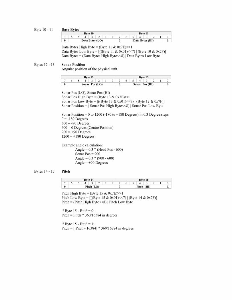
Byte 10 - 11 Data BytesByte 10 Byte 11
7 6 5 4 3 2 1 0 7 6 5 4 3 2 1 00 Data Bytes (LO) 0 Data Bytes (HI) L
Data Bytes High Byte = (Byte 11 & 0x7E)>>1Data Bytes Low Byte = [((Byte 11 & 0x01)<<7) | (Byte 10 & 0x7F)]Data Bytes = (Data Bytes High Byte<<8) | Data Bytes Low Byte
Bytes 12 - 13 Sonar PositionAngular position of the physical unit
Byte 12 Byte 137 6 5 4 3 2 1 0 7 6 5 4 3 2 1 00 Sonar Pos (LO) 0 Sonar Pos (HI) L
Sonar Pos (LO), Sonar Pos (HI)Sonar Pos High Byte = (Byte 13 & 0x7E)>>1Sonar Pos Low Byte = [((Byte 13 & 0x01)<<7) | (Byte 12 & 0x7F)]Sonar Position = ( Sonar Pos High Byte<<8) | Sonar Pos Low Byte
Sonar Position = 0 to 1200 (-180 to +180 Degrees) in 0.3 Degree steps0 = -180 Degrees300 = -90 Degrees600 = 0 Degrees (Centre Position)900 = +90 Degrees1200 = +180 Degrees
Example angle calculation:Angle = 0.3 * (Head Pos - 600)Sonar Pos = 900Angle = 0.3 * (900 - 600)Angle = +90 Degrees
Bytes 14 - 15 Pitch
Byte 14 Byte 157 6 5 4 3 2 1 0 7 6 5 4 3 2 1 00 Pitch (LO) 0 Pitch (HI) L
Pitch High Byte = (Byte 15 & 0x7E)>>1 Pitch Low Byte = [((Byte 15 & 0x01)<<7) | (Byte 14 & 0x7F)] Pitch = (Pitch High Byte<<8) | Pitch Low Byte
if Byte 15 - Bit 6 = 0:Pitch = Pitch * 360/16384 in degrees
if Byte 15 - Bit 6 = 1:Pitch = [ Pitch - 16384] * 360/16384 in degrees
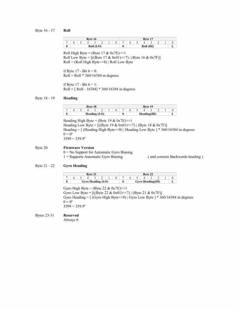
Byte 16 - 17 Roll
Byte 16 Byte 177 6 5 4 3 2 1 0 7 6 5 4 3 2 1 00 Roll (LO) 0 Roll (HI) L
Roll High Byte = (Byte 17 & 0x7E)>>1 Roll Low Byte = [((Byte 17 & 0x01)<<7) | (Byte 16 & 0x7F)] Roll = (Roll High Byte<<8) | Roll Low Byte
if Byte 17 - Bit 6 = 0:Roll = Roll * 360/16384 in degrees
if Byte 17 - Bit 6 = 1:Roll = [ Roll - 16384] * 360/16384 in degrees
Byte 18 - 19 Heading
Byte 18 Byte 197 6 5 4 3 2 1 0 7 6 5 4 3 2 1 00 Heading (LO) 0 Heading(HI) L
Heading High Byte = (Byte 19 & 0x7E)>>1 Heading Low Byte = [((Byte 19 & 0x01)<<7) | (Byte 18 & 0x7F)] Heading = [ (Heading High Byte<<8) | Heading Low Byte ] * 360/16384 in degrees0 = 0º 3599 = 359.9º
Byte 20 Firmware Version0 = No Support for Automatic Gyro Biasing1 = Supports Automatic Gyro Biasing ( and corrects Backwards heading )
Byte 21 - 22 Gyro Heading
Byte 21 Byte 227 6 5 4 3 2 1 0 7 6 5 4 3 2 1 00 Gyro Heading (LO) 0 Gyro Heading(HI) L
Gyro High Byte = (Byte 22 & 0x7E)>>1 Gyro Low Byte = [((Byte 22 & 0x01)<<7) | (Byte 21 & 0x7F)] Gyro Heading = [ (Gyro High Byte<<8) | Gyro Low Byte ] * 360/16384 in degrees0 = 0º 3599 = 359.9º
Bytes 23-31 ReservedAlways 0
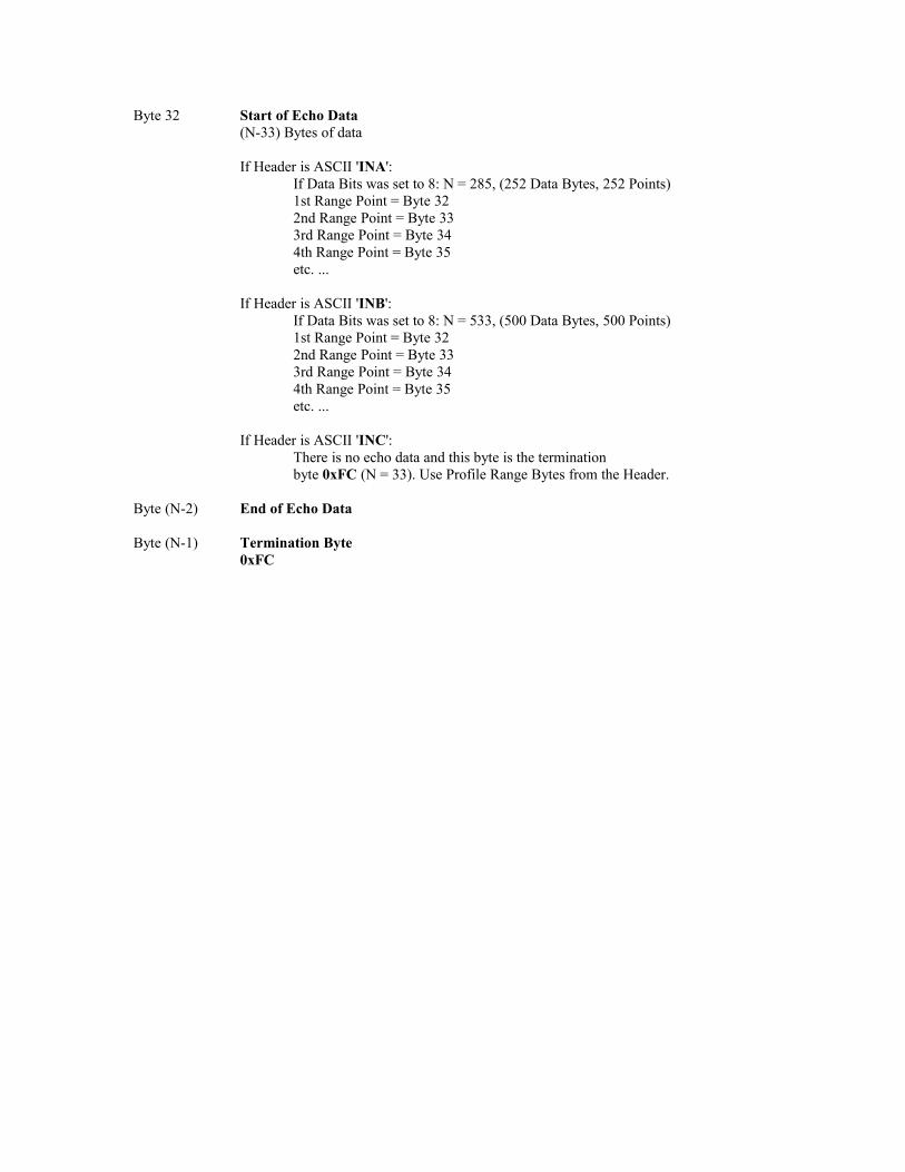
Byte 32 Start of Echo Data(N-33) Bytes of data
If Header is ASCII 'INA':If Data Bits was set to 8: N = 285, (252 Data Bytes, 252 Points)1st Range Point = Byte 322nd Range Point = Byte 333rd Range Point = Byte 344th Range Point = Byte 35etc. ...
If Header is ASCII 'INB':If Data Bits was set to 8: N = 533, (500 Data Bytes, 500 Points)1st Range Point = Byte 322nd Range Point = Byte 333rd Range Point = Byte 344th Range Point = Byte 35etc. ...
If Header is ASCII 'INC':There is no echo data and this byte is the terminationbyte 0xFC (N = 33). Use Profile Range Bytes from the Header.
Byte (N-2) End of Echo Data
Byte (N-1) Termination Byte0xFC