Embed Size (px)
Citation preview
IMAGE TO COME
Zimmer® Gender Solutions™
Patello-Femoral Joint (PFJ) System
Surgical Technique
Advancing the science of partial knee replacement.

INTRO
DescriptionThe Zimmer® Gender Solutions™ Patello-Femoral Joint Prosthesis (PFJ) is intended for replacement of the femoral trochlea of the patellofemoral joint that has been affected by the disease process and/or injury. The PFJ prosthesis may be used alone or with the Zimmer Unicompartmental Knee System or M/G® Unicompartmental Knee System to treat conditions of the patellofemoral or tibiofemoral regions of the knee. The PFJ prosthesis is compatible with either an unresurfaced patella, a NexGen® all-polyethylene, porous or augmentation patella or a Gender Solutions Natural-Knee® Flex all-polyethylene or metal-backed patella. PFJ prostheses are manufactured from Cobalt-Chromium-Molybdenum alloy and utilize Poly Methyl Methacrylate (PMMA) precoat.
Indications •Osteoarthritis,traumaticarthritis,polyarthritis,and/or severe chondrocalcinosis of the patellofemoral joint
•Thesalvageofpreviouslyfailedsurgicalattempts(e.g., arthroscopy, lateral release, cartilage transplantation)
•Historyofpatellardislocationorpatellafracture
•Dysplasia-inducedpatellofemoraldegeneration
This device is intended for cemented use only.
Contraindications •Previoushistoryofinfectionintheaffectedjointand/or local/systemic infection that may affect the prosthetic joint
•Insufficientbonestock
•Insufficientmenisciand/orligamentstructures
•Skeletalimmaturity
•Neuropathicarthropathy
•Severeinstability,maltracking,malalignmentofthepatella, patellofemoral and/or tibiofemoral joints
•Patellofemoralarthroplastyiscontraindicatedinpatients who have rheumatoid arthritis (RA) and an ulcer of the skin or a history of recurrent breakdown of the skin because their risk of postoperative infection is greater. RA patients using steroids may also have increased risk of infection. Late infections in RA patients have been reported 24+ months postoperative.
Zimmer® Gender Solutions™ Patello-Femoral Joint (PFJ) System

TOCTOC
1 Exposure
1 Exposure . . . . . . . . . . . . . . . . . . . . . . . . . . . . . . . . . . . . . . . . . . . . . . . . . . . . . 1
2 Resect Patella
Resecting the Patella. . . . . . . . . . . . . . . . . . . . . . . . . . . . . . . . . . . . . . . . . . . . 2
3 Mark Femoral Landmarks
Marking Femoral Anatomic Landmarks . . . . . . . . . . . . . . . . . . . . . . . . . . . . . 3
4 Perform Femoral Anterior Cut
4.1 Drilling the IM Hole . . . . . . . . . . . . . . . . . . . . . . . . . . . . . . . . . . . . . . . . . 4
4.2 Assembling the Telescoping Boom to the IM Anterior Cut Guide . . . . . 4
4.3 Inserting the IM Anterior Cut Guide with Telescoping Boom . . . . . . . . . 6
4.4 Setting External Rotation and Depth for Anterior Cut . . . . . . . . . . . . . . . 7
4.5 Securing the Guide and Making the Anterior Cut . . . . . . . . . . . . . . . . . . 9
5 Size Femoral Trochlea
5.1 Milling Guide Set-up and Positioning. . . . . . . . . . . . . . . . . . . . . . . . . . . 11
5.2 Trochlear Component Size Determination . . . . . . . . . . . . . . . . . . . . . . . 14
6 Mill Femoral Trochlea
6.1 Securing the Milling Guide . . . . . . . . . . . . . . . . . . . . . . . . . . . . . . . . . . . 16
6.2 Performing the Milling Operation. . . . . . . . . . . . . . . . . . . . . . . . . . . . . . 17
7 Drill Peg and Tail Holes
Drilling Peg and Tail Holes. . . . . . . . . . . . . . . . . . . . . . . . . . . . . . . . . . . . . . . . 22
8 Perform Trial Reduction
Performing Trial Reduction . . . . . . . . . . . . . . . . . . . . . . . . . . . . . . . . . . . . . . . 25
SECTION PAGE
Table of Contents
Zimmer® Gender Solutions™ Patello-Femoral Joint (PFJ) System
Zimmer® Gender Solutions™ Patello-Femoral Joint (PFJ) System Surgical Technique

TOCTOC
SECTION PAGE
9 Implant Trochlea and Patella Prostheses
9.1 Cementing/Implanting the PFJ Implant . . . . . . . . . . . . . . . . . . . . . . . . . 28
9.2 Cementing/Implanting the Patella and Checking Motion . . . . . . . . . . . 29
10 Bicompartmental Arthroplasty: Using the Zimmer Gender SolutionsPFJ with a Zimmer Unicompartmental Implant
10.1 Compatibility. . . . . . . . . . . . . . . . . . . . . . . . . . . . . . . . . . . . . . . . . . . . . . 30
10.2 Sequence - Implanting the Gender Solutions Patello-Femoral Joint First . . . . . . . . . . . . . . . . . . . . . . . . . . . . . . . . . . . 30
10.3 Unicondylar Technique . . . . . . . . . . . . . . . . . . . . . . . . . . . . . . . . . . . . . . 30
11 Closure
1 Closure. . . . . . . . . . . . . . . . . . . . . . . . . . . . . . . . . . . . . . . . . . . . . . . . . . . . . . . 31
Zimmer® Gender Solutions™ Patello-Femoral Joint (PFJ) System
1
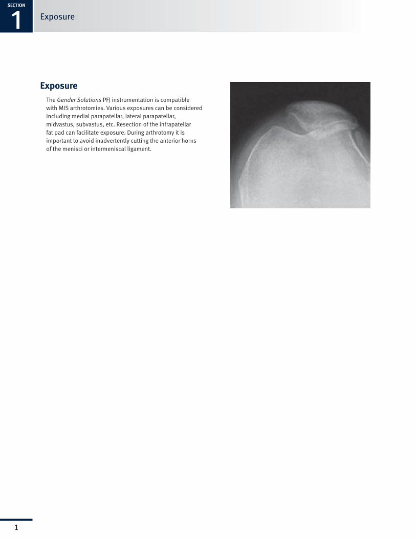
ExposureThe Gender Solutions PFJ instrumentation is compatible with MIS arthrotomies. Various exposures can be considered including medial parapatellar, lateral parapatellar, midvastus, subvastus, etc. Resection of the infrapatellar fatpadcanfacilitateexposure.Duringarthrotomyitis important to avoid inadvertently cutting the anterior horns of the menisci or intermeniscal ligament.
ExposureSECTION
1

SECTION
1
2
Surgical Technique HeaderSECTION
2
2
Resect Patella
Resect Patella• AfterselectingtheappropriateZimmerpatellarsystem,one of the following options may be used to prepare the patella.
- MIS Patella Resection Guide
- Standard Patella Instruments
- Patella Reamer System
• Selecttheappropriatesizepatellawhichprovidesforthebest support of the patella on the condyles after it transitions off of the trochlear component.

1SECTION
3
Surgical Technique Header3SECTION
3
Mark Femoral Landmarks•Mark the A/P axis (Whiteside’s line) from the lowest part of
the trochlea to the highest part of the intercondylar notch (Fig1).
•With a skin marker, mark a line perpendicular to the A/P axis (Fig2).
NOTE: These marks will serve as references in setting external rotation in subsequent steps.
Fig. 1
Mark the A/P axis.
Mark Femoral Landmarks
TECHNIQUE TIP 3.A
Technique Tip: Alternatively, the transepicondylar axis may be used as reference.
Fig. 2
Mark a line perpendicular to the A/P axis.

SECTION
1
4
Surgical Technique HeaderSECTION
4
4
Femoral Anterior Cut 4.1 Drilling the IM Hole
• Use the 6mm Intramedullary (IM) drill to drill the hole (Fig. 3).
NOTE: Hole location is 10 mm anterior to the origin of the posterior cruciate ligament.
4.2 Assembling the Telescoping Boom to the IM Anterior Cut Guide
• Unlock the Telescoping Boom by loosening the knurled knob. (Fig. 4).
NOTE: The locking boom (00-5983-028-00) is compatible with the IM Anterior Cut Guide and is available separately.
Femoral Anterior Cut
Fig.3
Drilling IM hole.
Fig.4
Unlock Telescoping Boom.

1SECTION
5
Surgical Technique Header4SECTION
5
• Push down and hold adjustment knob on the IM Anterior Cut Guide (Fig.5) while sliding the Telescoping Boom onto the IM guide collar (Fig.6). Boom may be inserted from either medial or lateral side.
• Release the IM guide adjustment knob.
• Lock the Telescoping Boom by tightening the knurled knob on the boom.
Femoral Anterior Cut
Fig.6
Slide on Telescoping Boom.
Fig.5
Push down and hold adjustment knob.
TECHNIQUE TIP 4.A
It may be necessary to slightly rotate adjustment knob while depressing to allow boom insertion.

SECTION
1
6
Surgical Technique HeaderSECTION
4
6
4.3 Inserting the IM Anterior Cut Guide With Telescoping Boom
• Insert the IM Guide into the medullary canal until the proxi-mal aspect of the guide slightly contacts the distal femoral sulcus. The guide may be inserted by hand (Fig. 7) or with the Inserter/Extractor handle (Fig. 8).
Femoral Anterior Cut
- If impaction is required, impact using the Inserter/ Extractor handle or impact directly on the IM Anterior Cut Guide only at the location marked “IMPACT AREA” (Fig. 9).
CAUTION: Avoid over-impacting the guide to prevent damage to the condyles.
NOTE: Impacting the proximal aspect of the IM Anterior Cut Guide could cause instrument damage and should be avoided.
TECHNIQUE TIP 4.B
To provide additional clearance for the Telescoping Boom to clear the anterior femur during insertion, adjust the IM guide to the “open” position (turning adjustment knob on top of IM guide counter-clockwise).
Fig.7
Insert by hand.
Fig.8
Optionally, insert with handle.
Fig.9
Impact where indicated.
C

1SECTION
7
Surgical Technique Header4SECTION
7
4.4 Setting External Rotation and Depth for Anterior Cut
• Rotate the IM guide to the desired external rotation.
- To align to the A/P axis, rotate the IM guide until the vertical reference lines on the guide are parallel with the A/P axis.
- If using transepicondylar axis or line perpendicular to the A/P axis, rotate until the horizontal lines on the guide are parallel to the marked lines. (Fig. 10).
TECHNIQUE TIP 4.C
Moving the knee closer to extension will improve visibility of the anterior femur.
Femoral Anterior Cut
Fig. 10
Setting external rotation parallel to marked lines.
Fig. 11
Creating a "flush" cut.
• Extend the knee and move the Telescoping Boom tip onto the lateral facet of anterior cortex (to help avoid notching).
- The goal is to create a flush cut with the anterior cortex. (Fig. 11).

SECTION
1
8
Surgical Technique HeaderSECTION
4
8
Femoral Anterior Cut
• Adjust A/P height of the cut guide by turning the IM guide adjustment knob until the boom tip just contacts the cortex (Fig. 12).
NOTE: Avoid excessive pressure on the boom tip.
• ConfirmanteriorcutwiththeResectionGuide(Fig.13).
Fig. 12
Adjusting height of cut guide.
Fig. 13
Confirm anterior cut.
1SECTION
9
Surgical Technique Header4SECTION
9
Femoral Anterior Cut
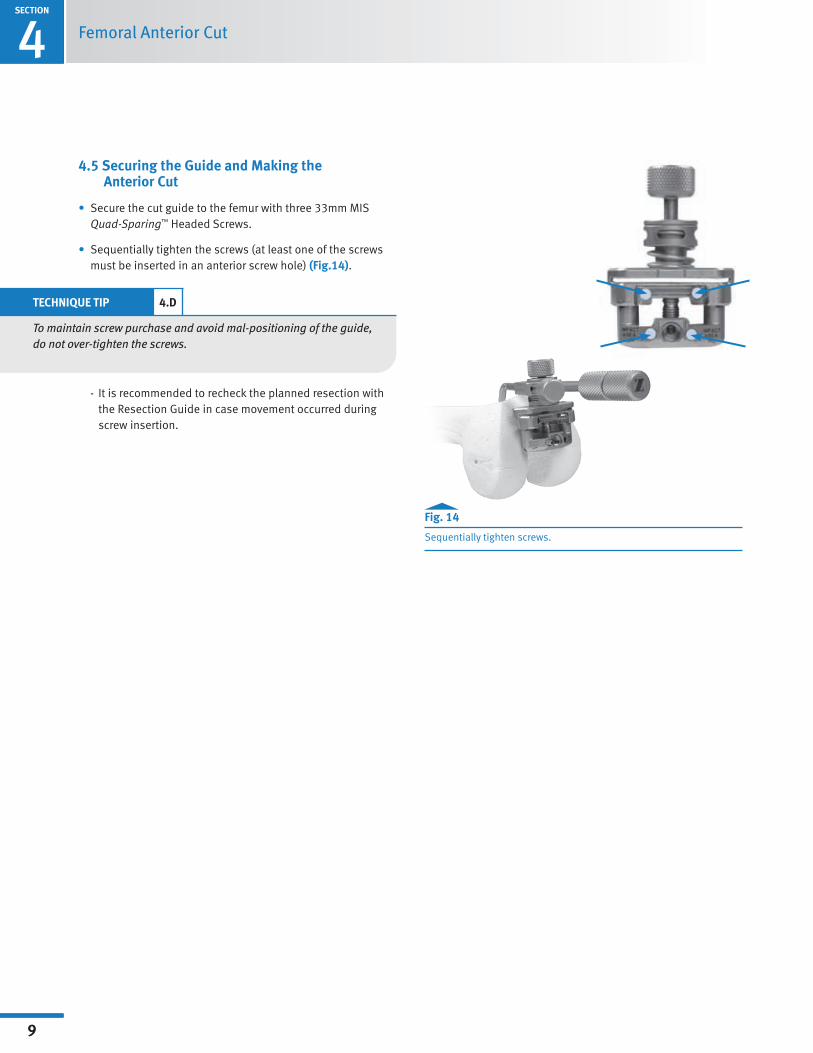
4.5 Securing the Guide and Making the Anterior Cut
• Secure the cut guide to the femur with three 33mm MIS Quad-Sparing™HeadedScrews.
• Sequentially tighten the screws (at least one of the screws must be inserted in an anterior screw hole) (Fig.14).
- It is recommended to recheck the planned resection with the Resection Guide in case movement occurred during screw insertion.
Fig. 14
Sequentially tighten screws.
TECHNIQUE TIP 4.D
To maintain screw purchase and avoid mal-positioning of the guide, do not over-tighten the screws.
SECTION
1
10
Surgical Technique HeaderSECTION
4
10
Femoral Anterior Cut
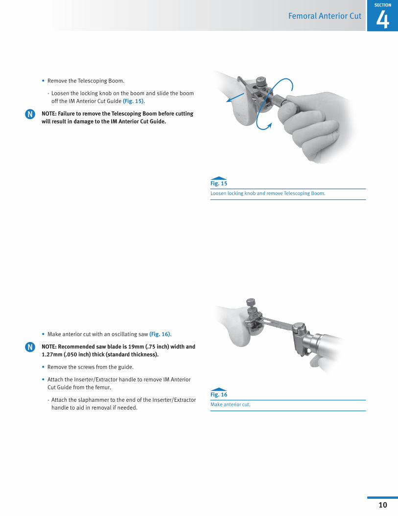
• Remove the Telescoping Boom.
- Loosen the locking knob on the boom and slide the boom off the IM Anterior Cut Guide (Fig. 15).
NOTE: Failure to remove the Telescoping Boom before cutting will result in damage to the IM Anterior Cut Guide.
• Make anterior cut with an oscillating saw (Fig. 16).
NOTE: Recommended saw blade is 19mm (.75 inch) width and 1.27mm (.050 inch) thick (standard thickness).
•Remove the screws from the guide.
• Attach the Inserter/Extractor handle to remove IM Anterior Cut Guide from the femur.
- Attach the slaphammer to the end of the Inserter/Extractor handle to aid in removal if needed.
Fig. 15
Loosen locking knob and remove Telescoping Boom.
Fig. 16
Make anterior cut.

1SECTION
11
Surgical Technique Header5SECTION
11
Fig. 17/18
Milling guides match the implant geometry and serve as sizing guides.
SIZE FEMORAL TROCHLEA5.1 Milling Guide Set-up and Positioning
NOTE: The Milling Guides are designed to match the outside geometry of the implant and therefore serve as sizing guides (Fig. 17-18).
• Select the appropriate size and side Milling Guide (Left or Right).
• Move the feet to the middle or “set” position as described below.
Size Femoral Trochlea
- Depressandholdthespring-loadedbuttonwhilepulling up or down on each foot until each foot is in the "set" position (Fig. 19).
- Tug slightly on the foot without the button depressed to ensure the foot is locked.
Fig. 19
Adjust feet to "set" position.
- When the feet are in the “set” position the gold band will not be visible.
"Set" Position
Anterior Flange Gold band not visibleFoot

SECTION
1
12
Surgical Technique HeaderSECTION
5
12
Size Femoral Trochlea
Fig. 20
Correct orientation of Milling Guide for sizing.
• Ensure the anterior flange and two feet of the guide are simultaneously in contact with femur during this step (Fig. 20).
Feet flush on surface of bone

1SECTION
13
Surgical Technique Header5SECTION
13
INCORRECT
INCORRECT
Fig. 23
Fig. 22
CORRECT
Size Femoral Trochlea
Fig. 21
Determine desired location on femur.
• If necessary, reposition Milling Guide both mediolaterally and in varus/valgus until the desired location on the femur is determined. (see section 5.2) (Fig. 21).
CAUTION: Incorrect sizing will result if the feet are not in the “set” position and the anterior flange and feet are not in contact with the femur. See examples of correct and incorrect positioning (Figs. 22-24).
Fig. 24
Correct and incorrect set/sizing position (Fig. 25).
C

SECTION
1
14
Surgical Technique HeaderSECTION
5
14
Size Femoral Trochlea
5.2 Trochlear Component Size Determination
• With the Milling Guide positioned properly as described previously, select the trochlear component size by evaluating the following:
- Mediolateral Coverage:
Anterior flange should cover anterior cut without overhang. A small amount of underhang/clearance is acceptable (Fig. 25).
The engraved line on the Milling Guide and the central milling track represents the location of the patellofemoral track on the implant and may be used as reference (Fig. 26).
Fig. 25
Flange should cover anterior cut without overhang.
NOTE: Mediolateral widths of the implants are in 4 to 5mm increments (Fig. 27).
Fig. 26
Use engraved line and central milling track as placement reference.
Fig. 27
Sizes in 4 to 5mm increments.
Size 1 Size 2 Size 3 Size 4 Size 5
1SECTION
15
Surgical Technique Header5SECTION
15
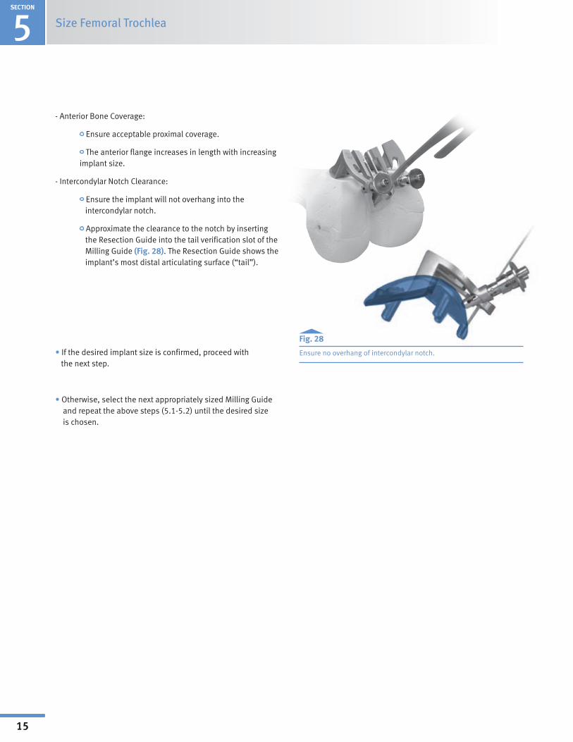
- Anterior Bone Coverage:
Ensure acceptable proximal coverage.
The anterior flange increases in length with increasing implant size.
-IntercondylarNotchClearance:
Ensure the implant will not overhang into the intercondylar notch.
Approximate the clearance to the notch by inserting the Resection Guide into the tail verification slot of the Milling Guide (Fig. 28). The Resection Guide shows the implant’s most distal articulating surface (“tail”).
•If the desired implant size is confirmed, proceed with the next step.
•Otherwise,selectthenextappropriatelysizedMillingGuide and repeat the above steps (5.1-5.2) until the desired size is chosen.
Size Femoral Trochlea
Fig. 28
Ensure no overhang of intercondylar notch.

SECTION
1
16
Surgical Technique Header
16
Mill Femoral Trochlea 6SECTION
Mill Femoral Trochlea6.1 Secure the Milling Guide
• Ensure the Milling Guide anterior flange is flat on the resected anterior bone cut with both feet in contact with the femur.
• The feet must be in the “set” position as described in section 5.1.
CAUTION: Failure to set both feet in direct contact with the cartilage will result in shallow bone preparation and distalization of the implant, leaving it proud relative to the condylar articular cartilage. This can result in patellar catching and snapping at the transition point. Care should be taken to avoid driving the feet too deep into the cartilage as this would result in proximalization of the implant, leaving it recessed excessively. The intention is to have the trochlear implant flush to 1mm recessed relative to the condylar cartilage. This will be achieved when both feet are just touching the condylar cartilage.
• Insert three 33mm MIS Quad-SparingHeadedscrews (00-5893-040-33) in the anterior flange of the guide.
• Tighten the screws sequentially in the following order:
- Central oblique screw (Fig. 29)
- Lateral screw (Fig. 30)
- Medial screw (Fig. 31)
Fig. 29
Tighten central oblique screw.
Fig. 30
Tighten lateral screw.
Fig. 31
Tighten medial screw.
TECHNIQUE TIP 6.A
To maintain screw purchase and avoid mal-positioning of the guide, do not over-tighten the screws.
•Use of the 33 mm screws will prevent violation of the posterior cortex.
•Re-verify the Milling Guide feet are touching cartilage and the anterior flange is resting flat on the anterior cut before proceeding.
- To reposition (if needed), remove the screws and repeat the above steps.
Central obliquescrew
Medial screw
Lateral screw
C
1SECTION
17
Surgical Technique Header6SECTION
17
Align red dots
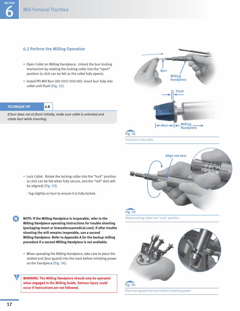
6.2 Perform the Milling Operation
•OpenColletonMillingHandpiece:Unlocktheburrlockingmechanism by rotating the locking collar into the “open” position (a click can be felt as the collet fully opens).
•Install PFJ Mill Burr (00-5927-050-00): Insert burr fully into collet until flush (Fig. 32).
•Lock Collet: Rotate the locking collar into the “lock” position (a click can be felt when fully secure, and the “red” dots will be aligned) (Fig. 33).
- Tug slightly on burr to ensure it is fully locked.
•WhenoperatingtheMillingHandpiece,takecaretoplacetheslotted end (burr guard) into the track before initiating power on the handpiece (Fig. 34).
WARNING: The Milling Handpiece should only be operated when engaged in the Milling Guide. Serious injury could occur if instructions are not followed.
Mill Femoral Trochlea
Fig. 32
Insert burr into collet.
Fig. 33
Rotate locking collar into "Lock" position.
Fig. 34
Place burr guard into track before initiating power.
Burr
Milling Handpiece
TECHNIQUE TIP 6.B
If burr does not sit flush initially, make sure collet is unlocked and rotate burr while inserting.
Burr Milling Handpiece
Flush
NOTE: If the Milling Handpiece is inoperable, refer to the Milling Handpiece operating instructions for trouble shooting (packaging insert or brasselerusamedical.com). If after trouble shooting the mill remains inoperable, use a second Milling Handpiece. Refer to Appendix A for the backup milling procedure if a second Milling Handpiece is not available.
N
!

SECTION
1
18
Surgical Technique HeaderSECTION
6
18
Mill Femoral Trochlea
•GuidetheMillingHandpiecewithahandonthelowerhalfof the handpiece, similar to holding a pencil (Fig. 35).
- Minimize binding or toggle by keeping the Milling HandpieceperpendiculartotheMillingGuide.
-Holdthehose(youorassistant)tominimize MillingHandpiecetoggle.
• The tracks should be milled in the order described below.
Fig. 35
Suggested holding position.
TECHNIQUE TIP 6.C
Run the Milling Handpiece at full throttle. If it stalls at any point, proceed more slowly through the tracks. Irrigation is not necessary with this device, but may be used if desired.
- Central track (Fig. 36)
o Apply slight and steady downward pressure while progressing distally along the central track.
o Be sure to mill the full length to the distal extreme of the central track.
o After central track milling is complete, disengage the throttle lever prior to exiting the track. Fig. 36
Milling the central track.
Central track
1SECTION
19
Surgical Technique Header6SECTION
19
Mill Femoral Trochlea
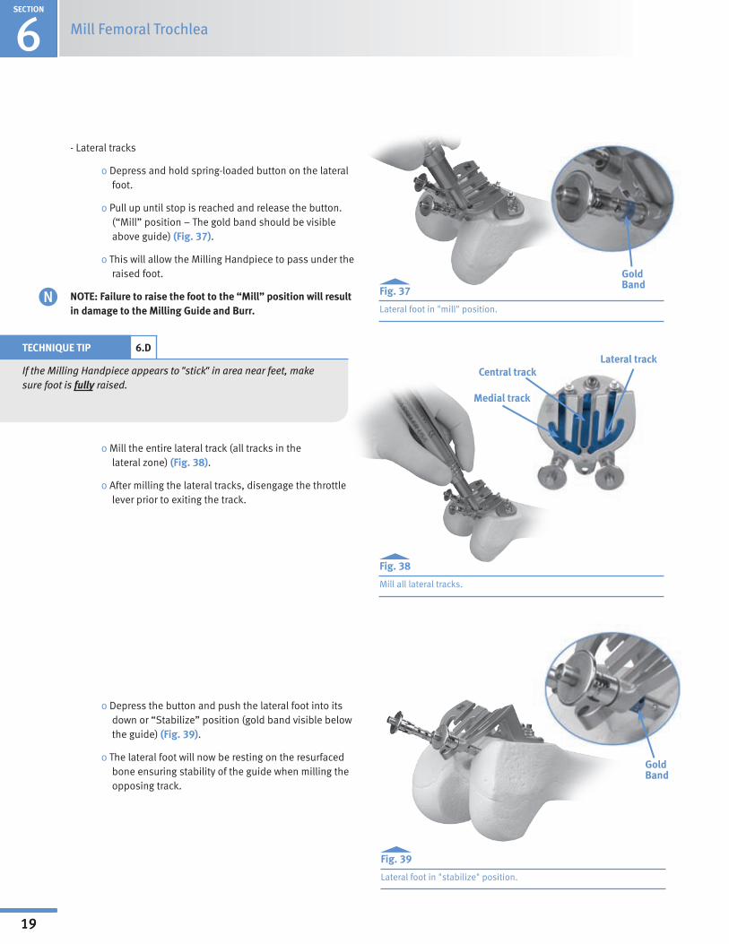
- Lateral tracks
oDepressandholdspring-loadedbuttononthelateralfoot.
o Pull up until stop is reached and release the button. (“Mill” position – The gold band should be visible above guide) (Fig. 37).
oThiswillallowtheMillingHandpiecetopassundertheraised foot.
NOTE: Failure to raise the foot to the “Mill” position will result in damage to the Milling Guide and Burr.
o Mill the entire lateral track (all tracks in the lateral zone) (Fig. 38).
o After milling the lateral tracks, disengage the throttle lever prior to exiting the track.
oDepressthebuttonandpushthelateralfootintoitsdown or “Stabilize” position (gold band visible below the guide) (Fig. 39).
o The lateral foot will now be resting on the resurfaced bone ensuring stability of the guide when milling the opposing track.
Fig. 37
Lateral foot in "mill" position.
Fig. 38
Mill all lateral tracks.
Fig. 39
Lateral foot in "stabilize" position.
Central track
Medial track
Lateral trackTECHNIQUE TIP 6.D
If the Milling Handpiece appears to "stick" in area near feet, make sure foot is fully raised.
GoldBand
GoldBand
SECTION
1
20
Surgical Technique HeaderSECTION
6
20
Mill Femoral Trochlea
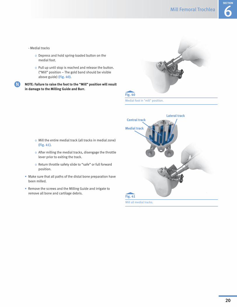
- Medial tracks
o Depressandholdspring-loadedbuttononthe medial foot.
o Pull up until stop is reached and release the button. (“Mill” position – The gold band should be visible above guide) (Fig. 40).
NOTE: Failure to raise the foot to the “Mill” position will result in damage to the Milling Guide and Burr.
o Mill the entire medial track (all tracks in medial zone) (Fig. 41).
o After milling the medial tracks, disengage the throttle lever prior to exiting the track.
o Return throttle safety slide to “safe” or full forward position.
•Make sure that all paths of the distal bone preparation have been milled.
•Remove the screws and the Milling Guide and irrigate to remove all bone and cartilage debris.
Fig. 40
Medial foot in "mill" position.
Fig. 41
Mill all medial tracks.
Central track
Medial track
Lateral track

1SECTION
21
Surgical Technique Header6SECTION
21
Mill Femoral Trochlea
•The bone preparation should appear as illustrated (Fig. 42).
•Please note that a small area of bone may remain distally but will be removed during the tail preparation.
- Freehand removal is not recommended.
Fig. 42
Bone Preparation
SECTION
1
22
Surgical Technique Header
22
7SECTION
Drill Peg and Tail Holes
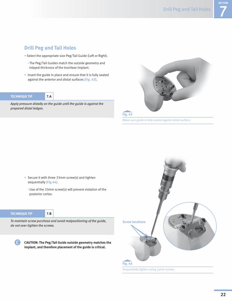
Drill Peg and Tail Holes• Select the appropriate size Peg/Tail Guide (Left or Right).
- The Peg/Tail Guides match the outside geometry and inlayed thickness of the trochlear implant.
• Insert the guide in place and ensure that it is fully seated against the anterior and distal surfaces (Fig. 43).
Fig. 43
Make sure guide is fully seated against distal surface.
Fig. 44
Sequentially tighten using 33mm screws.
• Secure it with three 33mm screw(s) and tighten sequentially (Fig.44).
- Use of the 33mm screw(s) will prevent violation of the posterior cortex.
TECHNIQUE TIP 7.A
Apply pressure distally on the guide until the guide is against the prepared distal ledges.
TECHNIQUE TIP 7.B
To maintain screw purchase and avoid malpositioning of the guide, do not over-tighten the screws.
CAUTION: The Peg/Tail Guide outside geometry matches the implant, and therefore placement of the guide is critical.
Screw locations
C
1SECTION
23
Surgical Technique Header
23
SECTION
Drill Peg and Tail Holes7
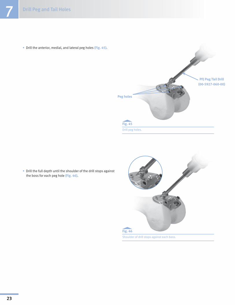
Peg holes
•Drilltheanterior,medial,andlateralpegholes(Fig. 45).
Fig. 45
Drill peg holes.
•Drillthefulldepthuntiltheshoulderofthedrillstopsagainstthe boss for each peg hole (Fig. 46).
Fig. 46
Shoulder of drill stops against each boss.
PFJ Peg/Tail Drill(00-5927-060-00)

SECTION
1
24
Surgical Technique Header
24
7Drill Peg and Tail HolesSECTION
•Drillthetailslot(distalovalpeg)by:
- Insert the drill into the entry hole on the left of the guide (Fig. 47).
Fig. 47
Drill the tail slot (distal oval peg).
TECHNIQUE TIP 7.C
Applying pressure (drill shaft) to the right with a finger may aid the drill movement (Fig. 48). Take care to prevent glove from catching.
-Oncetheuppershoulderonthedrillreachesthebosson the guide, continue drilling while sliding the drill from left to right.
o The drill’s upper shoulder must remain flush with the guide’s boss.
Fig. 48
Apply pressure to aid side-cutting action.
PFJ Peg/Tail Drill
Upper shoulder

25
8SECTION
Perform Trial Reduction
Perform Trial Reduction
•AttachtheInserter/ExtractorHandletotheappropriatesizePFJ Provisional (Left or Right) (Fig. 49).
TECHNIQUE TIP 8.A
The provisional can be inserted onto the femur by hand if desired (Fig. 50).
Fig. 49
Attach Inserter/Extractor handle.
Perform Trial Reduction
Fig. 50
Optionally, insert provisional by hand.

26
Perform Trial Reduction 8SECTION
•Insert the provisional onto the femur, taking care to properly align the pegs and tail with the holes (Fig. 51). The pegs should engage into peg holes at the same time.
Fig. 51
•Onceinsertedinplace,removethe Inserter/ExtractorHandleandimpact the provisional with the PFJ Impactor until it is fully seated.
- The impaction force should be delivered in the direction of the pegs’ axis (Figs. 51,52, and 53).
CAUTION: Some press-fit may be necessary to ensure an optimal fit, but be careful to avoid impinging or damaging cartilage at the transition area during impaction.
Fig. 52
Fig. 53
Correct and incorrect insertion angles.
CORRECT
INCORRECT
INCORRECT
C

27
8SECTION
Perform Trial Reduction
•Insert the appropriate Patella Provisional selected in Section 2.
•Evaluate patellofemoral tracking throughout range of motion.
NOTE: The patella should transition smoothly throughout range-of-motion.
Fig. 54
Cartilage at the edge of the anterior cut may be blended.
Fig. 55
Carefully remove provisional.
TECHNIQUE TIP 8.B
If necessary, remaining cartilage at the edge of the anterior cut shown circled in Fig. 54, in particular sharp corners, may be blended to prevent soft tissue irritation. Also, areas around the patella may be blended to prevent impingement and provide for smoother contact.
•Remove the Patella Provisional.
•Attach the Inserter/Extractor handle to the PFJ Provisional (trochlea) (Fig. 55).
•Carefully remove the provisional in the direction of the pegs’ axis.
- Attach slaphammer to the end of the Inserter/Extractor handle to aid in removal.
CAUTION: Do not rock the provisional back and forth during removal as this could compromise the bone preparation, peg hole preparation, surrounding cartilage, and the implant’s fit.
C
SECTION
1
28
Surgical Technique Header
28
9SECTION
Implant Trochlea and Patella Prosthesis
Implant Trochlea and Patella Prostheses
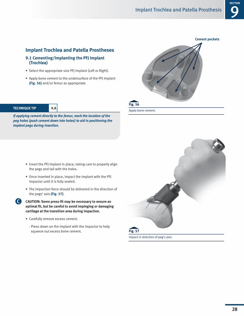
9.1 Cementing/Implanting the PFJ Implant (Trochlea)
•Select the appropriate size PFJ Implant (Left or Right).
•Apply bone cement to the undersurface of the PFJ Implant (Fig. 56) and/or femur as appropriate.
Fig. 56
Apply bone cement.
Fig. 57
Impact in direction of peg's axis.
•Insert the PFJ Implant in place, taking care to properly align the pegs and tail with the holes.
•Onceinsertedinplace,impacttheimplantwiththePFJImpactor until it is fully seated.
•The impaction force should be delivered in the direction of the pegs’ axis (Fig. 57).
CAUTION: Some press-fit may be necessary to ensure an optimal fit, but be careful to avoid impinging or damaging cartilage at the transition area during impaction.
•Carefully remove excess cement.
- Press down on the implant with the impactor to help squeeze out excess bone cement.
Cement pockets
TECHNIQUE TIP 9.A
If applying cement directly to the femur, mark the location of the peg holes (push cement down into holes) to aid in positioning the implant pegs during insertion.
C
1SECTION
29
Surgical Technique Header
29
9 Implant Trochlea and Patella ProsthesisSECTION
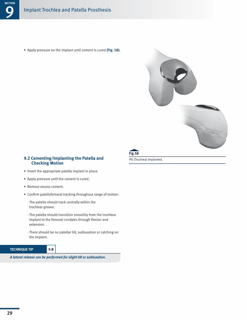
•Apply pressure on the implant until cement is cured (Fig. 58).
9.2 Cementing/Implanting the Patella and Checking Motion
•Insert the appropriate patella implant in place.
•Apply pressure until the cement is cured.
•Remove excess cement.
•Confirm patellofemoral tracking throughout range of motion.
- The patella should track centrally within the trochlear groove.
- The patella should transition smoothly from the trochlear implant to the femoral condyles through flexion and extension.
- There should be no patellar tilt, subluxation or catching on the implant.
Fig.58
PFJ (Trochlea) implanted.
TECHNIQUE TIP 9.B
A lateral release can be performed for slight tilt or subluxation.

SECTION
1
30
Surgical Technique Header
30
10SECTION
Bicompartmental Arthroplasty
Bicompartmental Arthroplasty
10.1 Compatibility
• The Zimmer Gender Solutions Patello-Femoral Joint System is compatible with the Zimmer Unicompartmental Knee System and the M/G Unicompartmental Knee System.
• Cadaveric testing has shown that adequate clearance between the Zimmer Gender Solutions Patello-Femoral and a Zimmer Unicompartmental Knee is achieved when proper surgical technique for both prostheses are followed (Fig. 59).
10.2 Sequence - Implanting the Zimmer Gender Solutions Patello-Femoral Joint First
• The Zimmer Gender Solutions Patello-Femoral Joint System may be used with Zimmer Unicompartmental implants, whether combined simultaneously or in a staged approach.
• In a staged approach, the Zimmer Gender Solutions PFJ and Zimmer Unicompartmental are implanted during separate surgical interventions. The Unicompartmental may be added to an existing PFJ or the PFJ may be added to an existing Unicompartmental.
• In a simultaneous approach, the Zimmer Gender Solutions Patello-Femoral Joint and Zimmer Unicompartmental Knee are implanted during the same surgical intervention. In this presentation, it is recommended that the Zimmer Gender Solutions Patello-Femoral Joint be implanted first. This sequence enables proper placement of the PFJ Milling Guide for resurfacing of the trochlea.
10.3 Unicondylar Technique
• The Zimmer Unicompartmental components should then be implanted using their respective surgical techniques. The SpacerBlockOptionisrecommendedwhenusingthe Zimmer Unicompartmental Knee System combined with the Zimmer Gender Solutions PFJ.
Fig. 59

1SECTION
31
Surgical Technique Header
31
11 ClosureSECTION
•CAUTION: Cleanse surgical site of bone chips, bone cement, or other debris as foreign particles at the articular interface may cause excessive wear.
•Suture/close

SECTION
1
32
Surgical Technique Header
32
Appendix A
Appendix A: Backup Milling ProcedureRationale:
ThePFJDrillMillingAdaptercanbeused to complete the milling operation intheeventtheMillingHandpieceisinoperable at the time of surgery. The DrillMillingAdapterjoinsthePFJMillBurr to a standard surgical drill via a Jacob’s Chuck and utilizes a PFJ Milling Guide for accurate bone preparation. The milling operation is more challenging when using this approach and should only be used as a backup to the Milling Handpiece.
Fig. 1 Insert burr into adapter
With a 1/4 in. or smaller Jacob’s Chuck facing upright, insert the shank of the PFJMillBurrwithPFJDrillMillingAdapterinto the Jacob’s Chuck until they both bottom out (Fig. 2). Tighten securely with chuck key (Fig. 3). Rotate assembly to visually verify that the burr is clamped straightandthatthePFJDrillMillingAdapter rotates independently from the PFJ Mill Burr.
Caution: To minimize the potential for over-resection, hold Jacob’s Chuck verti-cally during tightening and ensure there is no axial play in the assembly (Figs. 4 & 5).
Fig. 3 Tighten Jacob’s Chuck securely
Fig. 4 Backup Milling Assembly (CORRECT)
Place Backup Milling Assembly into a standard surgical drill.
Caution: The use of a reamer/wire driver is not recommended. Ensure the standard surgical drill/Jacob’s Chuck can achieve 750-25,000 rpm. Too slow/ fast may result in poor bone preparation and/or damage to the instruments.
2. Secure the Milling Guide: Additional Fixation
In addition to the three (3) anterior fixation screws, it is recommended to utilize a 48mm MIS headless screw (00-5983-041-48) in the Milling Guide’s posterior fixation hole when using this approach. This will help ensure adequate fixation (Fig. 6).
1. Assembly:
Insert new PFJ Mill Burr (00-5927-050-00)intothePFJDrillMilling Adapter as shown in (Fig. 1).
Fig. 2 Burr and adapter in Jacob’s Chuck
Fig. 6 Posterior screw insertion
CORRECT
Fig. 5 Backup Milling Assembly (INCORRECT)
INCORRECT
1SECTION
33
Surgical Technique Header
33
Appendix A
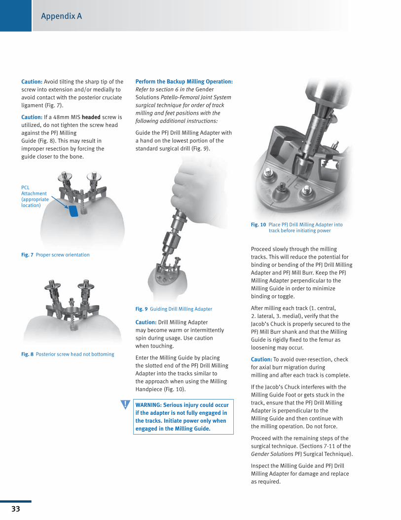
Perform the Backup Milling Operation:Refer to section 6 in the Gender Solutions Patello-Femoral Joint System surgical technique for order of track milling and feet positions with the following additional instructions:
GuidethePFJDrillMillingAdapterwitha hand on the lowest portion of the standard surgical drill (Fig. 9).
Fig. 9 GuidingDrillMillingAdapter
Caution: DrillMillingAdapter may become warm or intermittently spin during usage. Use caution when touching.
Enter the Milling Guide by placing theslottedendofthePFJDrillMillingAdapter into the tracks similar to the approach when using the Milling Handpiece(Fig.10).
WARNING: Serious injury could occur if the adapter is not fully engaged in the tracks. Initiate power only when engaged in the Milling Guide.
Fig. 10 PlacePFJDrillMillingAdapterinto track before initiating power
Proceed slowly through the milling tracks. This will reduce the potential for bindingorbendingofthePFJDrillMillingAdapter and PFJ Mill Burr. Keep the PFJ Milling Adapter perpendicular to the Milling Guide in order to minimize binding or toggle.
After milling each track (1. central, 2. lateral, 3. medial), verify that the Jacob’s Chuck is properly secured to the PFJ Mill Burr shank and that the Milling Guideisrigidlyfixedtothefemurasloosening may occur.
Caution: To avoid over-resection, check for axial burr migration during milling and after each track is complete.
If the Jacob’s Chuck interferes with the Milling Guide Foot or gets stuck in the track,ensurethatthePFJDrillMillingAdapter is perpendicular to the Milling Guide and then continue with themillingoperation.Donotforce.
Proceed with the remaining steps of the surgical technique. (Sections 7-11 of the Gender Solutions PFJ Surgical Technique).
InspecttheMillingGuideandPFJDrillMilling Adapter for damage and replace as required.
Caution: Avoid tilting the sharp tip of the screw into extension and/or medially to avoid contact with the posterior cruciate ligament (Fig. 7).
Caution: If a 48mm MIS headed screw is utilized, do not tighten the screw head against the PFJ Milling Guide (Fig. 8). This may result in improper resection by forcing the guide closer to the bone.
Fig. 7 Proper screw orientation
Fig. 8 Posterior screw head not bottoming
PCL Attachment (appropriate location)
!

Contact your Zimmer representative or visit us at www.zimmer.com
97-5926-002-00 Rev. 1 0811-K10 5ML Printed in USA ©2008, 2009 Zimmer, Inc.
+H124975926002001/$081106R1F09
Please refer to package insert for complete product information, including contraindications, warnings, precautions, and adverse effects.