Embed Size (px)
Citation preview
IEEE TRANSACTIONS ON ELECTROMAGNETIC COMPATIBILITY, VOL. 37, NO. 3, AUGUST 1995 463
Image Theory for the Unidirectionally Conducting Screen
Ismo V. Lindell
Abstract- Image theory is developed for electromagnetic sources in front of a planar unidirectionally conducting screen, made of ideally conducting parallel wires with thickness and interspace dimensions much smaller than the wavelength. Replacing the screen by the image sources gives the correct reflected and transmitted fields on the respective sides of the screen. The problem is solved through a decomposition of the original source in two parts, giving rise to fields TE and TM with respect to the direction of the wires. For the TE and TM source components, the images can be constructed from previous knowledge. For an electric dipole source, the images are seen to involve dipole and transmission-line SOU^^.
I. INTRODUCTION The unidirectionally conducting screen consists of a plane of
parallel perfectly conducting wires isolated from one another with thickness and interspace dimensions much smaller than the wave- length, so that the screen can be considered as a continuous surface. There have been studies on wave reflection from, and transmission through such a surface, as well as analyses of surface wave excitation and propagation along the surface [1]-[4], when the screen is in an isotropic medium. The uniconducting screen is a useful model for a parallel-wire shield or polarization screen for small-enough frequencies, which are of importance in electromagnetic engineering.
To solve general problems of electromagnetic fields due to sources in front of a uniconducting screen, an image theory analogous to that of a perfectly electrically conducting (PEC) or perfectly magnetically conducting (PMC) plane would be of great advantage. In terms of such a theory, any such problem can be reduced to one in homogeneous space, when the images of the sources are taken into account. Thus, existing computer codes based on the free-space Green function can be applied without making a new numerical code for the extended Green function corresponding to the screen. The present theory can also be seen as an extension of the corresponding static theory valid for dc current sources in a conducting medium [5], [6], although the approach is totally different. A parallel theory was recently constructed by the present author for the related soft and hard surface, which is basically a boundary realizable by a tuned corrugated surface [7]. The method applied was based on a T W decomposition of the source [8], [9], which was seen to split the problem in two simple ones. The same decomposition will be applied here.
11. THEORY The unidirectionally conducting screen is defined to exist on the
plane i = 0 in a homogeneous medium with parameters p , e . The direction of conductivity is assumed to be parallel to the x-axis. The electric field satisfies the condition
U, .E( , - 0) = 0 (1)
on both sides of the screen while the z component of the magnetic field and the y component of the electric field are continuous. The y component of the magnetic field at the screen has a discontinuity
Manuscript received June 16, 1994; revised April 26, 1995. The author is with the Electromagnetics Laboratory, Helsinki University of
IEEE Log Number 9413138. Technology, Otakaari 5A, Espoo 02150, Finland.
whose magnitude equals that of the surface current density (current per unit width) on the screen.
As primary sources in the half space z > 0, we consider an electric current source J (r) and a magnetic current source M( r). The objective of the paper is to find the reflection image sources Jv . M, in the region z < 0, which, together with the primary sources, gives rise to the total field in 2 > 0 without the presence of the screen. Similarly, the transmission image sources Jt, Mt in the region I > 0, giving the fields in the region 3 < 0, are looked after.
A. TE/TM Decomposition The primary sources J(r). M(r) are split in two components [8]
(2) (3)
The TE and Th4 source components create in a homogeneous space without the screen the respective electromagnetic fields ETE. HTE, and ET”, ~ T - 2 1 satisfying
J = JTE + JT“
M = MTE + M’”.
u, . ET” = 0. HTM = 0. (4)
It can be quite easily seen that, for a TE source (like a r-directed magnetic dipole), introduction of the screen does not change the field at all because the condition (1) is valid for the incident field. Since there are no induced currents in the screen, the magnetic field also satisfies the continuity condition at z = 0.
For the TM source, the screen acts like a PEC plane. In fact, a TM source (like a x-directed electric dipole) above a PEC plane induces currents which are parallel to the z-axis. Thus, the PEC plane can be replaced by the uniconducting screen without changing the current pattern.
The unidirectional screen can be seen as a TElTM filter, because it reflects the Th4 component and transmits the TE component of the electromagnetic field arising from any source. A dual screen with unidirectional magnetic conductivity would reflect the TE component and transmit the TM component.
TE Image: Because for a TE source the screen does not have any effect, it can be neglected. Thus, the reflection and transmission image sources corresponding to the screen are very simple in the TE case-there is no reflection image while the transmission image equals the original source
u2- .
JTE(r) = 0 ,
JFE(r) = JT”(r). MTE(r) = O ( 5 )
M:E(r) =M“‘”(r). (6)
TM Image: For the TM source, the screen can be replaced by a PEC plane, whence there is no transmitted image and the reflection image equals that of the PEC plane [9]
JT”(r) = 0,
J:”(r) = O (7)
The mirror reflection dyadic is defined as - - - - c = I - 2u,u,.
0018-9375/95$04.00 0 1995 IEEE
464 IEEE TRANSACTIONS ON ELJXTROhfAGNETIC COMPATIBILITY, VOL. 37, NO. 3, AUGUST 1995
Total Image: To sum up, we see that for a screen in a homoge-
J,(r) = -z. JTM(E.r) ,
neous isotropic space, the reflection and transmission images are
M,(r) = MTM ( E . r) (10)
Jt(r) = JTE(r),
Mt(r) =MTE(r). (1 1)
and they can be easily computed whenever the TEYlN decomposition for the original source has been found.
B. Electric Dipole Knowing the TE and TM components of the primary source leads
us directly to the expressions for its image. Let us consider the electric dipole, i.e., the electric current element. For any other source, the result can be obtained by integration. Assume the source
J(r) =ILS(r - u,h)
= ILS(z)6(y)6(2 - h) (12)
(13)
where I is a current vector defined by
I = u,I, + uyIy + u*I*.
It was shown in [7]-[9] that the TM/TE splitting can be written as a combination of dipole and line sources
TM J (r) = uz[u2 . J(r)l - U,G‘(~)LI. ~ [ 6 ( ~ ) 6 ( ~ - h)] (14)
JTE(r) = J(r) - JTM(r). (15)
Here, G(z) denotes the one-dimensional Green function defined by
G”(x) + kZG(z) = -6(z), G(z) = (16)
The line source can be interpreted as a transmission-line current [8], [9] fed by the projection of the original dipole in the yz, plane.
To check these expressions, we note that because the source JTM(r) is parallel to the z-axis, it produces in homogeneous space an electromagnetic field which satisfies u, . H = 0, or is TM to x. On the other hand, the source JTE = J - JTM can be shown to satisfy the condition
u, . ( k z f + VV) . JTE(r) = 0. (17)
Because the corresponding electric field satisfies the Helmholtz equation
2 j k
(0’ + k’)E(r) = j w p ( ? + a VV) . JTE(r) (18)
its z component E,(r) = u, . E(r) satisfies a source-free equation. From uniqueness of the physical field, the solution E, = 0 is thus valid everywhere and the field from JTE is really TE to 2.
The image sources corresponding to the electric dipole source (12) can be written from (lo), (1 1) in the form
J,(r) =-F.JTM(E.r) - - -u,U, . J ( F . r) + U , G ~ ( ~ ) L [ I ~ ~ ~ ( ~ ) S ( ~ + h )
- I A ( Y ) S ’ ( Z + h)] (19) Jt(r) = JTE(r)
-
= Tyz . J(r) - u,G’(z)L[Iy6’(y)6(z - h )
+ Iz6(y)6‘(z - h)] . (20) - -
with Iyz = uyuy + u a u n .
C. Magnetic Dipole The TFflXl decomposition for the magnetic dipole
M(r) =ImL6(r - u,h)
= ImL6(x)6(y)6(2 - h ) (21)
can be written from the duality principle. In fact, applying the simple duality transformation E -+ H, H + E, E + -p , p + --E,
J + -M, M + -J, implying I + -Im, for which the Maxwell equations are invariant, we can write the decomposition directly from (15), (14) by interchanging TE and TM
TE M (r) = uz[uz . M(r)l - u,G’(x)LI, . V[S(y)S(z - h)] (22)
MTM(r) =M(r) - MTE(r). (23)
If the same duality transformation is applied to the previously obtained image of the electric dipole, the image in the unidirectionally magnetically conducting screen is obtained. Applying the expressions (lo), (11) we obtain the image corresponding to the electrically conducting screen. The result is
Mt (r) = MTE (r) = u,uZ . I,L6(r - u,h)]
- u,G’(z)LI, . V[6(y)6(~ - h ) ] (24)
M, (r) = F . MTM ( E . r)
= (uyuy - u , u z ) . ImL6(r + u,h) - ~zG‘(x)L[Imy6’(~)6(~ + h ) - Im,6(y)6’(z + h)]. (25)
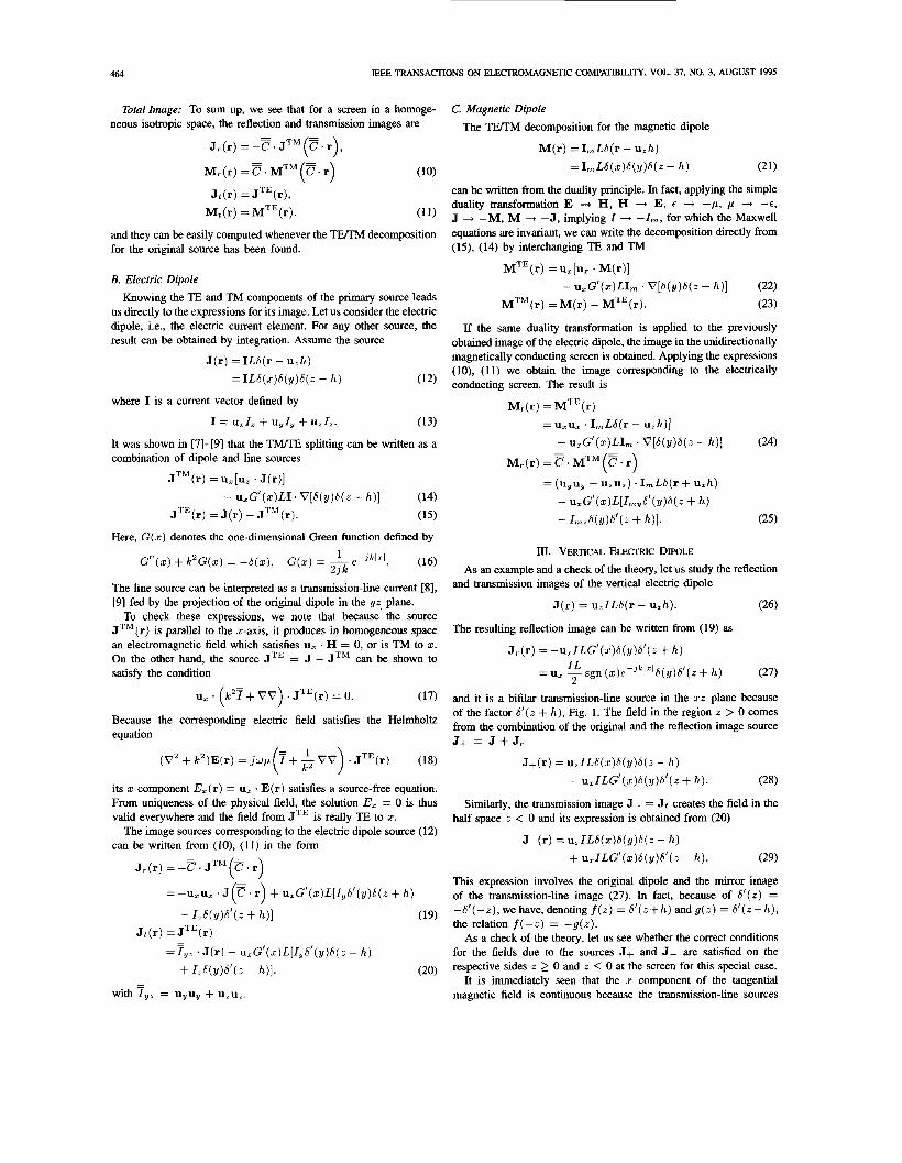
III. VERTICAL ELECTRIC DIPOLE As an example and a check of the theory, let us study the reflection
(26)
and transmission images of the vertical electric dipole
J(r) = u,ILS(r - u,h).
The resulting reflection image can be written from (19) as
J,.(r) = -u2ILG‘(z)6(y)6’(z + h )
(27) I L 2
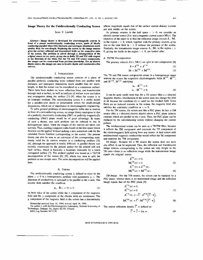
= u, - sgn ( z )e -~~ l~ l6 (y )6 ‘ (z + h )
and it is a bifilar transmission-line source in the xz plane because of the factor 6’(z + h), Fig. 1. The field in the region z > 0 comes from the combination of the original and the reflection image source J+ = J + J,
J+(r) = uZIL6(z)6(y)6(z - h )
- u,lLG‘(x)S(y)S‘(z + h). (28)
Similarly, the transmission image J- = Jt creates the field in the half space z < 0 and its expression is obtained from (20)
JL(r) = uZIL6(x)6(y)6(z - h)
+ u , ~ ~ ~ ‘ ( z ) 6 ( y ) 6 ’ ( z - h ) . (29)
This expression involves the original dipole and the mirror image of the transmission-line image (27). In fact, because of 6 ’ ( z ) = -6’(-z),wehave,denotingf(z) = 6’(z+h) andg(z) = 6 ‘ ( z - h ) , the relation f(-z) = -g(z).
As a check of the theory, let us see whether the correct conditions for the fields due to the sources J+ and J- are satisfied on the respective sides z 2 0 and z 5 0 at the screen for this special case.
It is immediately seen that the x component of the tangential magnetic field is continuous because the transmission-line sources
IEEE TRANSACTIONS ON ELECTROMAGNETIC COMPATIBILITY, VOL. 37, NO. 3, AUGUST 1995 465
Fig. 1. Vertical electric dipole J above a uniconducting screen, together with the continuous part of its reflection image J, consisting of a transmission-line current source.
of J+ and J- radiate no L component and the dipole sources are the same. The y component of the tangential magnetic field suffers a jump which is created by the transmission-line sources.
Conditions for the electric field at the screen can be found by developing the source expressions
s+, = u, . (k’+ CV) . J+(r)
=ILS’(s )6(y)[6‘ (2 - h) + S ‘ ( Z + h)] (30)
(31) SL, = u , . (k’?+ VV ) . J-(r) = 0.
s+, = u, . ( k 2 7 + GO) . J+(r)
=ILS’(y){S(.z)[6’(2 - h ) + 6’(L + h)]
+ k 2 G ( z ) S ‘ ( z + h ) }
s-, = u, . (k’? + CV) . J-(r)
= - ILk2G(z)6’ (y)S’ (z - h ) .
Taking the z component of the Helmholtz equation
and inserting the zero from (31), shows us that for t < 0 the E, component vanishes, Le., that the transmitted field has TE polarization. Because the function s+, is antisymmetric in t, (30) shows that so is the corresponding solution E,, where at the screen in the half space 2 2 0, we have the correct boundary condition E, = 0 satisfied.
Finally, let us consider the y component of (34) and insert (32), (33) to the right-hand sides. The term in square brackets in (32) is antisymmetric in L and gives zero field at L = 0 while the remaining term and (33) are a symmetric pair in t and hence, produce the same E, component at the screen.
We have thus shown, in this special case, that applying the image sources, the fields satisfy the correct boundary conditions: E, vanishes on both sides of the screen and E,, H, are continuous across the screen.
IV. SUMMARY
Image theory has been developed for the unidirectionally con- ducting screen, which has applications in screening and polarization transfonnation. The theory applies TE/Iu decomposition of the primary source with respect to the direction of conductivity. It is seen that the screen is invisible to the TE component and perfectly reflecting to the Th4 component. Image sources of a dipole perpen- dicular to the screen is studied, and as a check, the fields are seen to satisfy the correct boundary conditions at the screen.
REFERENCES
S. N. Karp, “Diffraction of a plane wave by a unidirectionally conducting half plane,” Courant Znst. Math. Sci., Div. EM Res. Rep. no. EM-108, 1957. S. N. Karp and F. C. Karal, Jr., “Excitation of surface waves on a unidirectionally conducting screen by a phased line source,” ZEEE Trans. Antennas Propagat., vol. 12, no. 4, pp. 470-478, 1964. S. R. Seshadri, “Plane wave reflection and transmission by a unidi- rectionally conducting screen,” in Proc. ZEEE, vol. 57, pp. 722-724, 1969. J. C. Monzon, “Excitation of surface waves on a unidirectionally conducting screen by an arbitrary phased line source parallel to it,” ZEEE Trans. Antennas Propagat., vol. 36, no. 2, pp. 258-268, Feb. 1988. I. V. Lindell and M. J. Flykt, “Image theory for DC problems involving a conducting half space bounded by a perfect anisotropic surface,” IEEE Trans. Electromagn. Compat.. vol. 36, no. 2, pp. 92-96, May 1994. - , “Image theory for DC problems involving a conducting half space bounded by the general anisotropic impedance surface,” Radio Sci., vol. 29, no. 2, pp. 441450, Mar./Apr. 1994. I. V. Lindell, “Image theory for the soft and hard surface,” ZEEE Trans. Antennas Propagut., vol. 43, no. 1, pp. 117-119, Ian. 1995. __ , “TE/Iu decomposition of electromagnetic sources,” ZEEE Trans. Antennas Propagat., vol. 36, no. 10, pp. 1382-1388, Oct. 1988. -, Methodsfor Electromagnetic Field Anatysis. Oxford Clarendon Press, 1992.
Field Dynamics in a Parallel-Plate Simulator
J. S. Seregelyi, S. Kashyap, and A. Louie
Abstruct-Establishing the properties of the excitation field is critical in the process of evaluating the electromagnetic susceptibiiity of a piece of equipment. This paper examines the electric and magnetic fields gen- erated in and around a large parallel plate simulator, both numerically, using the numerical electromagnetic code (NEC) 111, and experimentally, in an effort to better understand the field dynamics inherent to the system. Comparison of the computed and measured results shows good correlation. In addition, the contribution of the three sections (front taper, middle section, and back taper) of the simulator are numerically isolated and the contribution of each to the overall field waveshape is discussed. The optimal positioning of a test object is determined based on the above results.
Manuscript received July 1, 1994; revised January 30, 1995. J. S. Seregelyi is with the Communications Research Centre, 3701 Carling
S. Kashyap and A. Louie are with the Defence Research Establishment
IEEE Log Number 9413135.
Avenue, P.O. Box 11490, Station “H,” Ottawa, ON Canada, K2H 8S2.
Ottawa, 3701 Carling Avenue, Ottawa, ON Canada, KIA O D .
0018-9375/95$04.00 0 1995 IEEE