Embed Size (px)
Citation preview
GeoEye Proprietary. © 2012 GeoEye, Inc. All Rights Reserved
Overview of Image Quality Performance of the GeoEye-1 High Resolution Imaging Satellite
Nancy E. Podger, PhD
GeoEye
JACIE, April 18, 2012
Overview
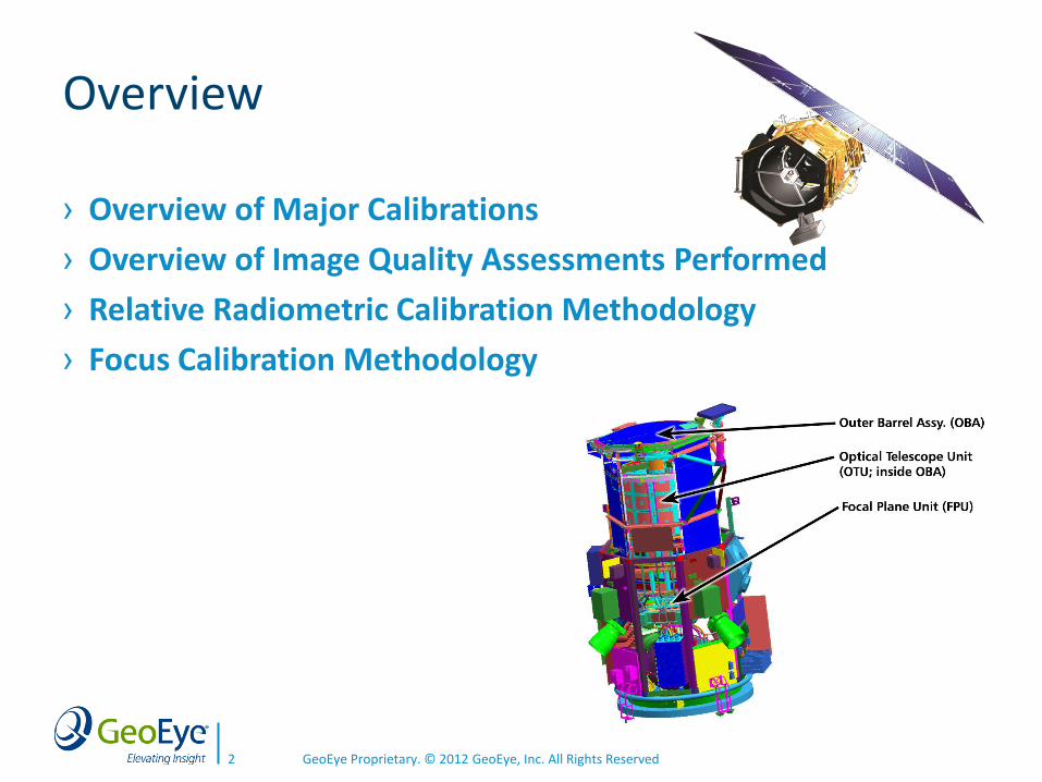
› Overview of Major Calibrations
› Overview of Image Quality Assessments Performed
› Relative Radiometric Calibration Methodology
› Focus Calibration Methodology
GeoEye Proprietary. © 2012 GeoEye, Inc. All Rights Reserved 2
Overview of Major Calibrations for the GE-1 sensor
› Geometric ‒ Geometric calibration provides the mapping of the satellite sensor for
geopositioning imagery.
› Radiometric ‒ Relative radiometric calibration is a detector equalization process to
reduce pixel-to-pixel and sub-array to sub-array variations.
‒ Absolute radiometric is the mapping between digital pixel values and at aperture spectral radiance.
› Focus ‒ Focus calibration is the process of determining the best focus position
of the secondary mirror of telescope.
GeoEye Proprietary. © 2012 GeoEye, Inc. All Rights Reserved 3
Overview of Major Image Quality Assessments
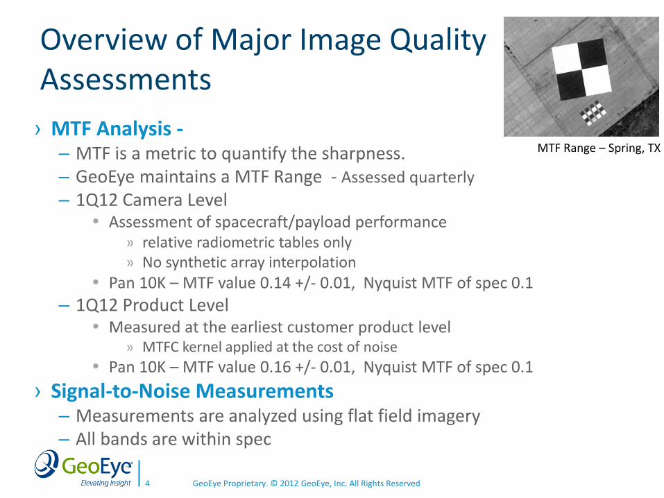
› MTF Analysis - ‒ MTF is a metric to quantify the sharpness. ‒ GeoEye maintains a MTF Range - Assessed quarterly
‒ 1Q12 Camera Level Assessment of spacecraft/payload performance
» relative radiometric tables only » No synthetic array interpolation
Pan 10K – MTF value 0.14 +/- 0.01, Nyquist MTF of spec 0.1
‒ 1Q12 Product Level Measured at the earliest customer product level
» MTFC kernel applied at the cost of noise
Pan 10K – MTF value 0.16 +/- 0.01, Nyquist MTF of spec 0.1
› Signal-to-Noise Measurements ‒ Measurements are analyzed using flat field imagery ‒ All bands are within spec
GeoEye Proprietary. © 2012 GeoEye, Inc. All Rights Reserved 4
MTF Range – Spring, TX
Overview of Major Image Quality Assessments (cont.)
› Time Delay Integration (TDI) Selection Optimization ‒ TDI selection controls detector exposure time (charged
integration time)
‒ TDI stages for GE-1 Panchromatic - 8,16,32,48,64
Multispectral - 3, 6, 10, 14, 18, 21, 24
‒ Optimum selection of TDI is needed to consistently obtain wide dynamic ranges without saturation when imaging.
› Visual assessment of operational imagery for artifact/anomaly characterization and resolution.
GeoEye Proprietary. © 2012 GeoEye, Inc. All Rights Reserved 5
Relative Radiometric Calibration
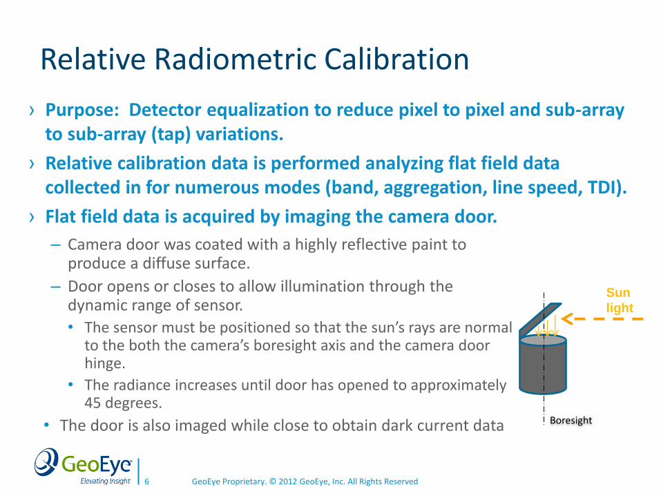
‒ Camera door was coated with a highly reflective paint to produce a diffuse surface.
‒ Door opens or closes to allow illumination through the dynamic range of sensor.
• The sensor must be positioned so that the sun’s rays are normal to the both the camera’s boresight axis and the camera door hinge.
• The radiance increases until door has opened to approximately 45 degrees.
• The door is also imaged while close to obtain dark current data
GeoEye Proprietary. © 2012 GeoEye, Inc. All Rights Reserved 6
Sun
light
Boresight
› Purpose: Detector equalization to reduce pixel to pixel and sub-array to sub-array (tap) variations.
› Relative calibration data is performed analyzing flat field data collected in for numerous modes (band, aggregation, line speed, TDI).
› Flat field data is acquired by imaging the camera door.
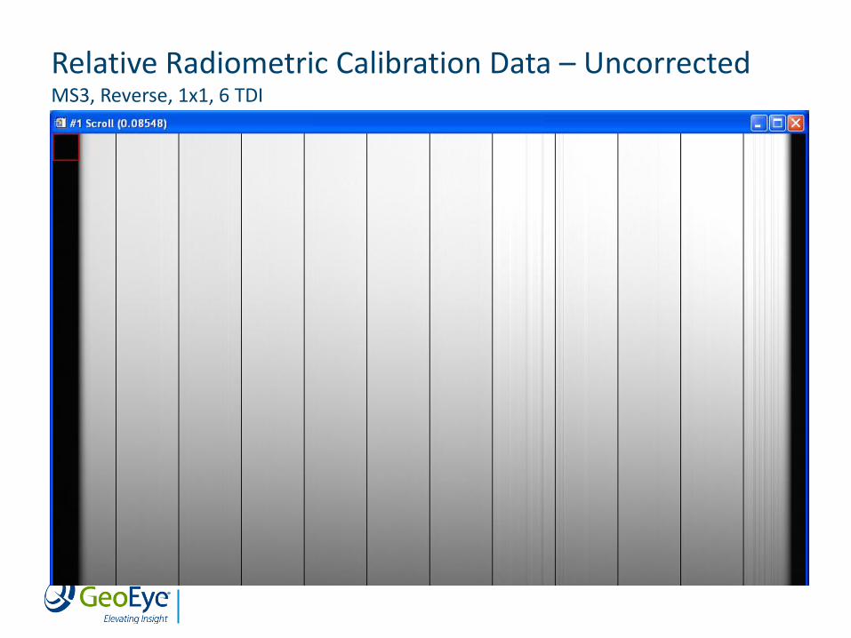
Relative Radiometric Calibration Data – Uncorrected MS3, Reverse, 1x1, 6 TDI
Relative Radiometric Calibration Methodology
› Dark current value per detector
‒ Calculated from data acquired when the camera door is closed.
‒ An average value from approx. 100 scan lines is calculated for each detector.
› Gain correction
‒ Seven illumination (light) level responses are calculated from the door data for each detector
average of approximately 100 lines.
‒ The dark current value is subtracted from each light levels for each detector.
‒ Target responses for each light level is determined by the mean value of the 500 middle detector values.
‒ The target responses and the light levels for each detector make up a lookup table
Piecewise linear interpolation during image reconstruction for any digital pixel value
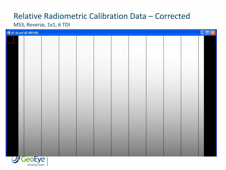
Relative Radiometric Calibration Data – Corrected MS3, Reverse, 1x1, 6 TDI
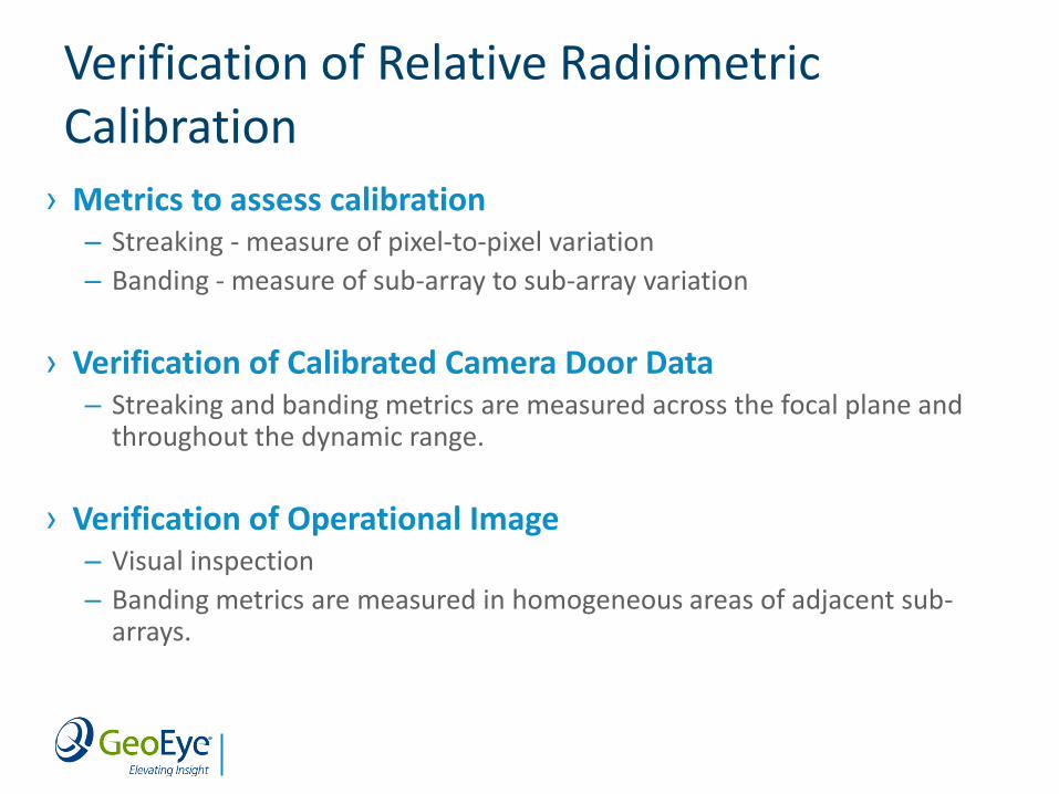
Verification of Relative Radiometric Calibration
› Metrics to assess calibration ‒ Streaking - measure of pixel-to-pixel variation
‒ Banding - measure of sub-array to sub-array variation
› Verification of Calibrated Camera Door Data ‒ Streaking and banding metrics are measured across the focal plane and
throughout the dynamic range.
› Verification of Operational Image ‒ Visual inspection
‒ Banding metrics are measured in homogeneous areas of adjacent sub-arrays.
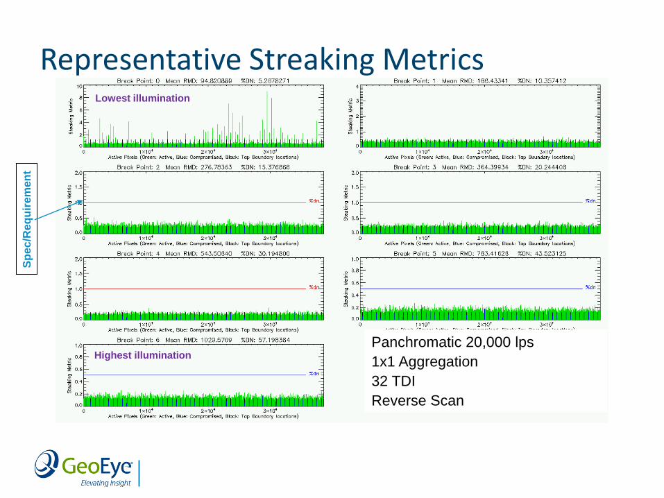
Representative Streaking Metrics S
pec
/Re
qu
ire
men
t
Panchromatic 20,000 lps
1x1 Aggregation
32 TDI
Reverse Scan
Lowest illumination
Highest illumination
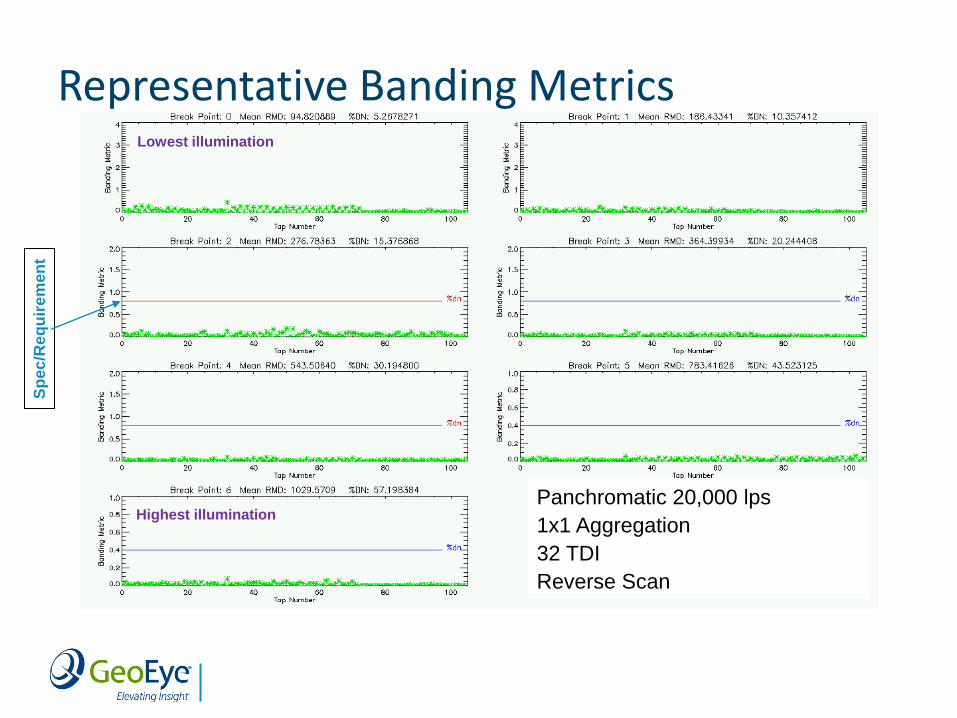
Representative Banding Metrics
Panchromatic 20,000 lps
1x1 Aggregation
32 TDI
Reverse Scan
Sp
ec
/Re
qu
ire
men
t
Lowest illumination
Highest illumination
Focus Calibration
› Focus calibration is performed to determine the best focus position of the secondary mirror of telescope.
› Methodology for Obtaining Best Focus ‒ Acquire a “through-focus” image by continuously changing focus during
a scan by slewing secondary mirror.
‒ Measure image sharpness by a digital edge detector throughout the “through-focus” image.
‒ A polynomial curve is fitted to the edge detector metrics and the maximum determines the optimum focus (secondary mirror position).
GeoEye Proprietary. © 2012 GeoEye, Inc. All Rights Reserved 13
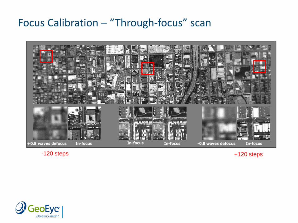
Focus Calibration – “Through-focus” scan
In-focus+0.8 waves defocus -0.8 waves defocusIn-focus In-focus In-focus
-120 steps +120 steps
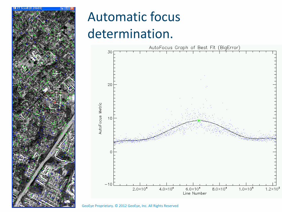
Automatic focus determination.
GeoEye Proprietary. © 2012 GeoEye, Inc. All Rights Reserved 15
Summary
› The GE-1 system continues to provide high quality imagery
› GE-1 remains in specification ‒ Radiometric
‒ Geometric
‒ MTF
‒ SNR
› Scans are continuously monitored to maintain high image quality.
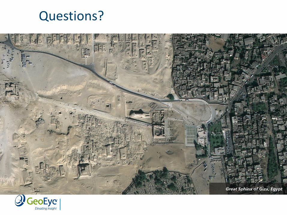
Questions?
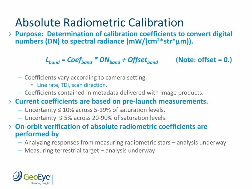
Absolute Radiometric Calibration › Purpose: Determination of calibration coefficients to convert digital
numbers (DN) to spectral radiance (mW/(cm2*str*m)).
Lband = Coefband * DNband + Offsetband (Note: offset = 0.)
‒ Coefficients vary according to camera setting. Line rate, TDI, scan direction.
‒ Coefficients contained in metadata delivered with image products.
› Current coefficients are based on pre-launch measurements. ‒ Uncertainty ≤ 10% across 5-19% of saturation levels. ‒ Uncertainty ≤ 5% across 20-90% of saturation levels.
› On-orbit verification of absolute radiometric coefficients are performed by ‒ Analyzing responses from measuring radiometric stars – analysis underway ‒ Measuring terrestrial target – analysis underway


![Lossless Image Compression through Super-Resolution … · 2020-04-07 · image given a low-resolution image [6,10,13,20,26,28,29,34,44,45,48,53,56]. Recent works have advanced the](https://img.pdfslide.us/doc/110x75/5f99ad0a9f53825d9c514c46/lossless-image-compression-through-super-resolution-2020-04-07-image-given-a-low-resolution.jpg)