Embed Size (px)
Citation preview

11
Image Processing Based Image Processing Based Autonomous Bradley RoverAutonomous Bradley Rover
Bradley University Bradley University -- ECE DepartmentECE DepartmentMay 3, 2005May 3, 2005
Team Members:Team Members: Steve GogginsSteve GogginsPete LangePete LangeRob ScherbinskeRob Scherbinske
Advisors:Advisors: Dr. HugginsDr. HugginsDr. MalinowskiDr. MalinowskiDr. SchertzDr. Schertz
Secondary Advisors:Secondary Advisors: Dr. StewartDr. StewartDr. AhnDr. AhnMr. SanchezMr. Sanchez

22
OutlineOutline
Project DescriptionProject DescriptionStatus of CompletionStatus of CompletionFuture OpportunityFuture OpportunityQuestionsQuestions

33
Project DescriptionProject Description
Block DiagramBlock DiagramAutonomous Vehicle Autonomous Vehicle NavigationNavigation
Global NavigationGlobal NavigationLocal NavigationLocal Navigation
Wireless Communication Wireless Communication LinkLinkPower Distribution CircuitPower Distribution Circuit

44
Project DescriptionProject Description
Block DiagramBlock DiagramAutonomous Vehicle Autonomous Vehicle NavigationNavigation
Global NavigationGlobal NavigationLocal NavigationLocal Navigation
Wireless Communication Wireless Communication LinkLinkPower Distribution CircuitPower Distribution Circuit

55
PC
GPS Receiver
Digital Compass
Linear Actuator
8051RF
Transceiver
Internet
Stereoscopic Cameras
Mission Control Web Server
RF Transceiver
UserClient C
Steering
Battery Power
Power Distribution
Photons
GP
S S
igna
l
Motors Speed
Project Description Project Description (Block Diagram)(Block Diagram)

66
Project DescriptionProject Description
Block DiagramBlock DiagramAutonomous Vehicle Autonomous Vehicle NavigationNavigation
Global NavigationGlobal NavigationLocal NavigationLocal Navigation
Wireless Communication Wireless Communication LinkLinkPower Distribution CircuitPower Distribution Circuit

77
Global NavigationGlobal Navigation
Sensor InputSensor InputGPS GPS –– to to –– local coordinate conversionlocal coordinate conversionNavigation algorithmNavigation algorithmMicrocontroller implementationMicrocontroller implementationChallengesChallengesSummarySummary
88
Global NavigationGlobal Navigation
Sensor InputSensor InputGPS GPS –– to to –– local coordinate conversionlocal coordinate conversionNavigation algorithmNavigation algorithmMicrocontroller implementationMicrocontroller implementationChallengesChallengesSummarySummary

99
Global NavigationGlobal Navigation(Sensor Input (Sensor Input –– GPS Receiver)GPS Receiver)
AshtechAshtech G8 GPS Receiver chosenG8 GPS Receiver chosenNMEA message protocol employedNMEA message protocol employedJava serial port interface writtenJava serial port interface writtenGraceful initialization, communication, and Graceful initialization, communication, and disconnect accomplisheddisconnect accomplishedApproximately 4 meter accuracy (nonApproximately 4 meter accuracy (non--differential) taken into accountdifferential) taken into account

1010
Global NavigationGlobal Navigation(Sensor Input (Sensor Input –– Digital Compass)Digital Compass)PNI Magnetometer mounted on PNI Magnetometer mounted on CommBoardCommBoard chosenchosenNMEA message protocol employedNMEA message protocol employedJava serial port interface writtenJava serial port interface writtenInterference accounted forInterference accounted for

1111
Global NavigationGlobal Navigation(Sensor Input)(Sensor Input)
GPS Receiver InputGPS Receiver InputNED flatNED flat--plane approximation coordinate plane approximation coordinate conversion from GPS latitude and longitudeconversion from GPS latitude and longitudeSouthwest corner reference obtained with Southwest corner reference obtained with 1000 data points1000 data points
Compass Heading InputCompass Heading InputApplicationApplication--specific calibrationspecific calibrationInterference accounted forInterference accounted for

1212
Global NavigationGlobal Navigation
Sensor InputSensor InputGPS GPS –– to to –– local coordinate conversionlocal coordinate conversionNavigation algorithmNavigation algorithmMicrocontroller implementationMicrocontroller implementationChallengesChallengesSummarySummary

1313
Local East CoordinateLocal East Coordinate
Local North CoordinateLocal North Coordinate
Global NavigationGlobal Navigation(Coordinate Conversion)(Coordinate Conversion)
)_()180
cos( referencelongitudelongitudelatitudeRadiusEquatorialEast −×Π
××=
180)_( Π×−×= referencelatitudelatitudesPolarRadiuNorth

1414
Global NavigationGlobal Navigation
Sensor InputSensor InputGPS GPS –– to to –– local coordinate conversionlocal coordinate conversionNavigation algorithmNavigation algorithmMicrocontroller implementationMicrocontroller implementationChallengesChallengesSummarySummary

1515
Global NavigationGlobal Navigation(Algorithm)(Algorithm)
South West Reference
Point
Current Rover Location(East,North)
Rover Destination(Destination
East,Destination North)
Rover Heading
Destination Angle
Heading Angle

1616
Global NavigationGlobal Navigation(Algorithm)(Algorithm)
Heading Angle and Destination Angle Heading Angle and Destination Angle comparedcomparedComparison dictates left or right turn for Comparison dictates left or right turn for RoverRoverHigh and low range allowed for possible High and low range allowed for possible turning overshootturning overshoot

1717
Global NavigationGlobal Navigation
Sensor InputSensor InputGPS GPS –– to to –– local coordinate conversionlocal coordinate conversionNavigation algorithmNavigation algorithmMicrocontroller implementationMicrocontroller implementationChallengesChallengesSummarySummary

1818
Global NavigationGlobal Navigation(Microcontroller Implementation)(Microcontroller Implementation)SC26C92 DUART used for serial SC26C92 DUART used for serial communicationcommunicationACSII message received from Rover ACSII message received from Rover laptoplaptopMessage read to specify turning commandMessage read to specify turning commandMotors & linear actuator engaged by Motors & linear actuator engaged by onboard port pinsonboard port pins

1919
Global NavigationGlobal Navigation
Sensor InputSensor InputGPS GPS –– to to –– local coordinate conversionlocal coordinate conversionNavigation algorithmNavigation algorithmMicrocontroller implementationMicrocontroller implementationChallengesChallengesSummarySummary

2020
Global NavigationGlobal Navigation(Challenges)(Challenges)
Satellite switching & building interferenceSatellite switching & building interferenceDifferential GPS would helpDifferential GPS would helpPerhaps a higherPerhaps a higher--mounted antenna would mounted antenna would helphelp
Digital compass interferenceDigital compass interferenceLaptop shieldedLaptop shieldedMicrocontroller shieldedMicrocontroller shielded

2121
Global NavigationGlobal Navigation
Sensor InputSensor InputGPS GPS –– to to –– local coordinate conversionlocal coordinate conversionNavigation algorithmNavigation algorithmMicrocontroller implementationMicrocontroller implementationChallengesChallengesSummarySummary

2222
Global NavigationGlobal NavigationSummarySummary
Bradley University quad successfully Bradley University quad successfully mapped with local coordinatesmapped with local coordinatesGPS & digital compass successfully GPS & digital compass successfully integrated with navigation algorithmintegrated with navigation algorithmNavigation algorithm successfully Navigation algorithm successfully implementedimplementedCommunication to microcontroller Communication to microcontroller successfully implementedsuccessfully implemented

2323
Project DescriptionProject Description
Block DiagramBlock DiagramAutonomous Vehicle Autonomous Vehicle NavigationNavigation
Global NavigationGlobal NavigationLocal NavigationLocal Navigation
Wireless Communication Wireless Communication LinkLinkPower Distribution CircuitPower Distribution Circuit
2424
Local NavigationLocal Navigation(Object Avoidance)(Object Avoidance)
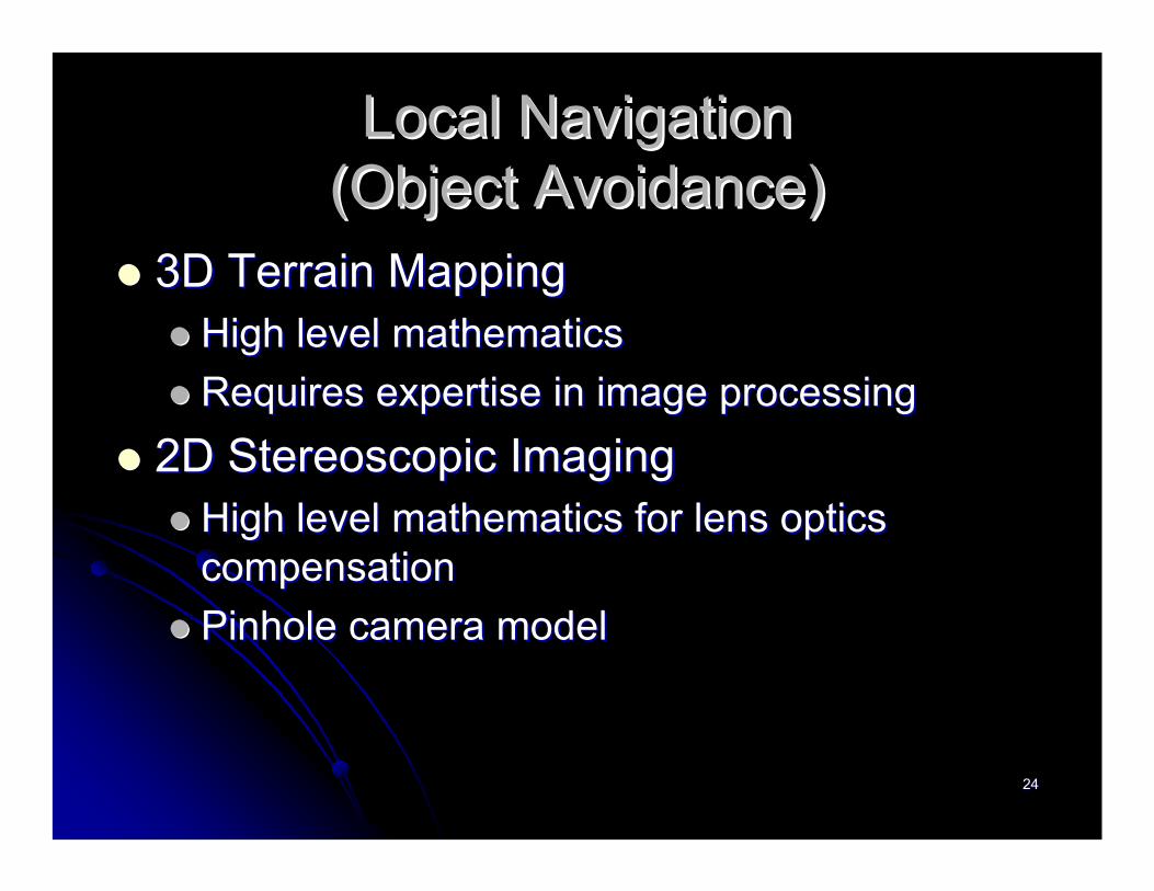
3D Terrain Mapping 3D Terrain Mapping High level mathematicsHigh level mathematicsRequires expertise in image processingRequires expertise in image processing
2D Stereoscopic Imaging2D Stereoscopic ImagingHigh level mathematics for lens optics High level mathematics for lens optics compensationcompensationPinhole camera model Pinhole camera model

2525
Local NavigationLocal Navigation(Camera Platform)(Camera Platform)
Matlab Matlab Image Acquisition ToolboxImage Acquisition ToolboxImage Processing ToolboxImage Processing Toolbox
CamerasCameras2x Logitech USBv1.1 Buddy Cams2x Logitech USBv1.1 Buddy Cams
Rover must be stopped to capture imagesRover must be stopped to capture images
InitializationInitializationMatlab startup and preview windowsMatlab startup and preview windows

2626
Local NavigationLocal Navigation(Task Breakdown)(Task Breakdown)
25% research 25% research –– over 30 conference/ over 30 conference/ journal papers, Matlab toolbox textjournal papers, Matlab toolbox text25% writing and debugging Matlab code25% writing and debugging Matlab code50% exploring options, collecting data, 50% exploring options, collecting data, testing datatesting data

2727
Local NavigationLocal Navigation(Object Detection Methods)(Object Detection Methods)
Edge Detection (unsuccessful)Edge Detection (unsuccessful)Contrast Levels (unsuccessful)Contrast Levels (unsuccessful)Combination of Contrast and Edge Combination of Contrast and Edge Detection (unsuccessful)Detection (unsuccessful)
Color Spectrum Analysis (Successful!)Color Spectrum Analysis (Successful!)Requires object of known colorRequires object of known color
2828
Local NavigationLocal Navigation(How Stereoscopic Imaging Works)(How Stereoscopic Imaging Works)
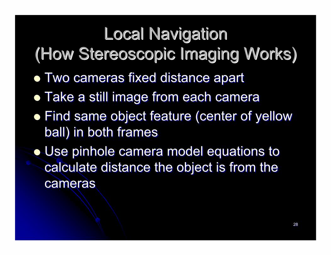
Two cameras fixed distance apartTwo cameras fixed distance apartTake a still image from each cameraTake a still image from each cameraFind same object feature (center of yellow Find same object feature (center of yellow ball) in both framesball) in both framesUse pinhole camera model equations to Use pinhole camera model equations to calculate distance the object is from the calculate distance the object is from the camerascameras

2929
Local NavigationLocal Navigation(Imaging Algorithm)(Imaging Algorithm)
Read original imagesRead original imagesFilter all but RGB yellow pixelsFilter all but RGB yellow pixelsFilter out gray RGB pixelsFilter out gray RGB pixelsConvert images to binaryConvert images to binaryCrop out remaining object in imagesCrop out remaining object in imagesUse cropped images to correlate and get Use cropped images to correlate and get objectobject’’s center location in each frames center location in each frameUse center locations to compute object distanceUse center locations to compute object distance

3030
Object Avoidance
Original Images
Filtered Yellow

3131
Object Avoidance
Grayscale Images
Cropped Images

3232
Local NavigationLocal Navigation(Object Classification)(Object Classification)
Use lookUse look--up table to compute distance up table to compute distance instead of pinhole equationsinstead of pinhole equationsClassify object into 6 rangesClassify object into 6 ranges

3333
Local NavigationLocal Navigation(Imaging Algorithm Output )(Imaging Algorithm Output )
Three parameters required by Global Three parameters required by Global Navigation algorithmNavigation algorithm
Object present?Object present?Range (1Range (1--6)6)Left of Right of RoverLeft of Right of Rover
Written to test fileWritten to test file
3434
Local NavigationLocal Navigation(Imaging Algorithm Shortcomings )(Imaging Algorithm Shortcomings )
Object partially off of frame results in Object partially off of frame results in wrong classificationwrong classification
Algorithm only works for 1 yellow object at Algorithm only works for 1 yellow object at a timea time

3535
Image Processing SummaryImage Processing Summary
Have single yellow object detection from Have single yellow object detection from less than 6 feet to about 22 feetless than 6 feet to about 22 feet6 classification ranges6 classification rangesUses empirical data in a lookUses empirical data in a look--up table to up table to determine distancedetermine distanceCommunicates with global navigation via Communicates with global navigation via text filestext files

3636
Project DescriptionProject Description
Block DiagramBlock DiagramAutonomous Vehicle Autonomous Vehicle NavigationNavigation
Global NavigationGlobal NavigationLocal NavigationLocal Navigation
Wireless Communication Wireless Communication LinkLinkPower Distribution CircuitPower Distribution Circuit

3737
WirelessWireless--G PCI adapter with G PCI adapter with removable antenna at removable antenna at ““Mission Mission ControlControl””
Replace factory antenna with designed Replace factory antenna with designed antennaantenna
WirelessWireless--G portable USB adapter on G portable USB adapter on Rover PCRover PC
Antenna is nonAntenna is non--removableremovablePointPoint--toto--point communication point communication
Minimal interferenceMinimal interference
802.11 Wireless Link802.11 Wireless Link
3838
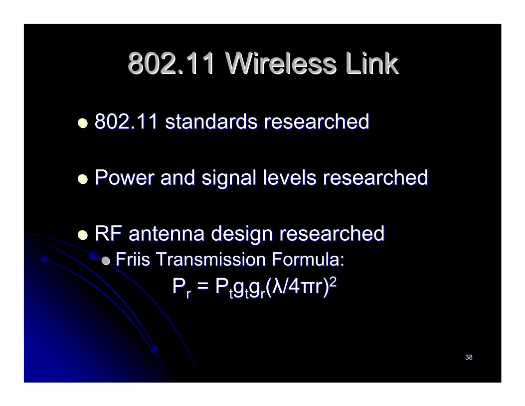
802.11 Wireless Link802.11 Wireless Link
802.11 standards researched802.11 standards researched
Power and signal levels researchedPower and signal levels researched
RF antenna design researchedRF antenna design researchedFriis Transmission Formula:Friis Transmission Formula:
PPrr = = PPttggttggrr((λλ/4/4ππrr))22

3939
Friis Transmission Friis Transmission Formula Example:Formula Example:
PPrr = = PPttggttggrr((λλ/4/4ππrr))22
Rewritten as:Rewritten as:PPrr(dBm(dBm) = ) = PPtt(dBm)+G(dBm)+Gtt(dB)+G(dB)+Grr(dB)(dB)--FSL(dBFSL(dB))where FSL = 20logwhere FSL = 20log1010((44ππr/ r/ λλ) ) ––Free Space LossFree Space Loss
Note: Note: λλ = c/f (wavelength)= c/f (wavelength)where c = 3*10where c = 3*1088 m/sm/s
and f = frequency [Hz]and f = frequency [Hz]

4040
AssumptionsAssumptions--Transmit Power of 19dBm (PTransmit Power of 19dBm (Ptt = 19)= 19)Transmitter Gain of 0dB (Transmitter Gain of 0dB (GGtt = 0)= 0)Receiver Gain of 0dB (Receiver Gain of 0dB (GGrr = 0)= 0)Distance of 200 meters (r = 200)Distance of 200 meters (r = 200)Frequency of 2.4GHz (Frequency of 2.4GHz (λλ = 0.125)= 0.125)
PPrr = 19dBm + 0dB + 0dB = 19dBm + 0dB + 0dB –– 20log20log1010((44ππ*200/0.125)*200/0.125)PPrr = = --67dBm67dBm
--Receiver with sensitivity of Receiver with sensitivity of --67dBm is required67dBm is required
Friis Transmission Friis Transmission Formula Example:Formula Example:

4141
Wireless Link SummaryWireless Link Summary
Initial steps taken to establish wireless linkInitial steps taken to establish wireless linkMethod determinedMethod determinedDesign researchedDesign researchedSample calculations madeSample calculations made
Final steps left for futureFinal steps left for futureFocus turned to rover powerFocus turned to rover powerJava interface put on holdJava interface put on hold

4242
Project DescriptionProject Description
Autonomous Vehicle NavigationAutonomous Vehicle NavigationGlobal NavigationGlobal NavigationLocal NavigationLocal Navigation
WebWeb--Based Rover ControlBased Rover ControlWireless Communication LinkWireless Communication LinkPower Distribution CircuitPower Distribution Circuit

4343
Power DistributionPower Distribution
Power to motorsPower to motorsPower to linear actuatorPower to linear actuatorPower to microcontrollerPower to microcontrollerPower to USB hubPower to USB hub

4444
Power DistributionPower Distribution
Two 12Two 12--V batteries provide power to all V batteries provide power to all electronics on board the roverelectronics on board the rover1212--V battery V battery ‘‘AA’’ powers motors & linear powers motors & linear actuatoractuator1212--V battery V battery ‘‘BB’’ powers microcontroller & powers microcontroller & USB hubUSB hub55--V signal provided by 12V signal provided by 12--V battery V battery ‘‘BB’’converted by DC/DC converterconverted by DC/DC converter

4545
Power DistributionPower Distribution
Power to motorsPower to motorsPower to linear actuatorPower to linear actuatorPower to microcontrollerPower to microcontrollerPower to USB hubPower to USB hub

4646
Power DistributionPower Distribution(Power to Motors)(Power to Motors)
Previous work by Ramona Cone & Erin Previous work by Ramona Cone & Erin CundiffCundiff
Motor model for PSPICEMotor model for PSPICEComplicated control circuit designComplicated control circuit design
Simplified control circuit designSimplified control circuit designRemoved unneeded componentsRemoved unneeded componentsEnded up with completely different designEnded up with completely different design
Current & voltage issues resolvedCurrent & voltage issues resolved

4747
Power DistributionPower Distribution(Power to Motors)(Power to Motors)
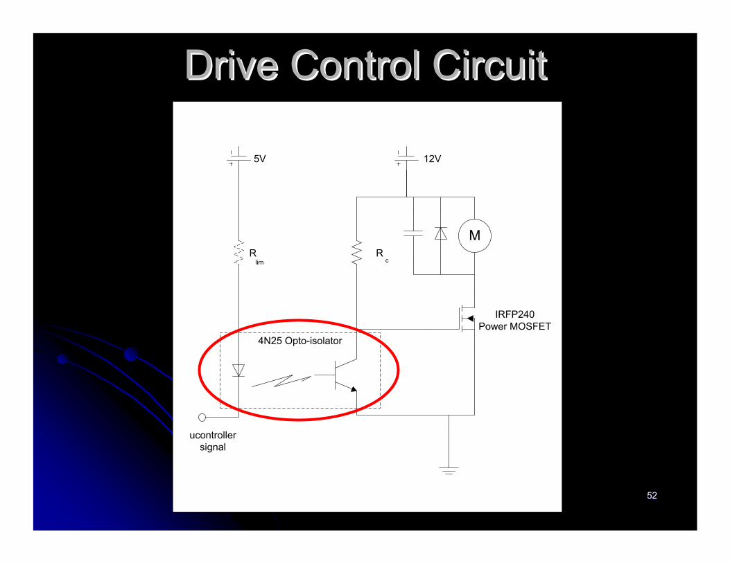
Control signal provided by microcontrollerControl signal provided by microcontroller
OptoOpto--isolator isolates microcontroller from DC isolator isolates microcontroller from DC motormotor
1212--V battery V battery ‘‘AA’’ powers drive motors through powers drive motors through IRFP240 power IRFP240 power MOSFETMOSFET’’ss
1212--V battery V battery ‘‘BB’’ provides 5provides 5--V signal needed for V signal needed for circuitrycircuitry

4848
Drive Control CircuitDrive Control Circuit
MR R
lim c
4N25 Opto-isolator
ucontrollersignal
5V 12V
IRFP240Power MOSFET

4949
Drive Control CircuitDrive Control Circuit
MR R
lim c
4N25 Opto-isolator
ucontrollersignal
5V 12V
IRFP240Power MOSFET

5050
Drive Control CircuitDrive Control Circuit
MR R
lim c
4N25 Opto-isolator
ucontrollersignal
5V 12V
IRFP240Power MOSFET

5151
Drive Control CircuitDrive Control Circuit
MR R
lim c
4N25 Opto-isolator
ucontrollersignal
5V 12V
IRFP240Power MOSFET
5252
Drive Control CircuitDrive Control Circuit
MR R
lim c
4N25 Opto-isolator
ucontrollersignal
5V 12V
IRFP240Power MOSFET

5353
Drive Control CircuitDrive Control Circuit
MR R
lim c
4N25 Opto-isolator
ucontrollersignal
5V 12V
IRFP240Power MOSFET

5454
Drive Control CircuitDrive Control Circuit
MR R
lim c
4N25 Opto-isolator
ucontrollersignal
5V 12V
IRFP240Power MOSFET

5555
Power DistributionPower Distribution
Power to motorsPower to motorsPower to linear actuatorPower to linear actuatorPower to microcontrollerPower to microcontrollerPower to USB hubPower to USB hub

5656
Power DistributionPower Distribution(Power to Linear Actuator)(Power to Linear Actuator)
Controlled by LMD18200 HControlled by LMD18200 H--BridgeBridge
1212--V battery V battery ‘‘AA’’ powers the linear actuatorpowers the linear actuator
Control signals provided by microcontrollerControl signals provided by microcontroller

5757
Power DistributionPower Distribution(Power to Linear Actuator)(Power to Linear Actuator)
LMD18200 HLMD18200 H--bridgebridgeSignals from microcontrollerSignals from microcontroller
Direction (high vs. low)Direction (high vs. low)Brake (high = brake, low = no brake)Brake (high = brake, low = no brake)PWM (75% duty cycle from previous group)PWM (75% duty cycle from previous group)
Supply BypassingSupply BypassingC = 4uF C = 4uF –– bypasses currents of inductive loadbypasses currents of inductive loadTransorbTransorb –– bibi--directional diode (extra protection)directional diode (extra protection)
BootstrapBootstrapC = 10nF C = 10nF –– charge pump to switch charge pump to switch FETFET’’ss

5858
Steering Control CircuitSteering Control Circuit
PWM
DIRECTION
BRAKE
V = 12V
C = 10nF
C = 4uF
C = 10nF

5959
Steering Control CircuitSteering Control Circuit
PWM
DIRECTION
BRAKE
V = 12V
C = 10nF
C = 4uF
C = 10nF

6060
Steering Control CircuitSteering Control Circuit
PWM
DIRECTION
BRAKE
V = 12V
C = 10nF
C = 4uF
C = 10nF

6161
Steering Control CircuitSteering Control Circuit
PWM
DIRECTION
BRAKE
V = 12V
C = 10nF
C = 4uF
C = 10nF

6262
Power DistributionPower Distribution
Power to motorsPower to motorsPower to linear actuatorPower to linear actuatorPower to microcontrollerPower to microcontrollerPower to USB hubPower to USB hub

6363
Power DistributionPower Distribution(Power to Microcontroller)(Power to Microcontroller)
Powered directly by 12Powered directly by 12--V battery V battery ‘‘BB’’
Internal circuitry converts 12Internal circuitry converts 12--V signal to 5VV signal to 5V
No external circuitry neededNo external circuitry needed

6464
Power DistributionPower Distribution
Power to motorsPower to motorsPower to linear actuatorPower to linear actuatorPower to microcontrollerPower to microcontrollerPower to USB hubPower to USB hub

6565
Power DistributionPower Distribution(Power to USB Hub)(Power to USB Hub)
1212--V battery V battery ‘‘BB’’ converted to 5V through converted to 5V through DC/DC converterDC/DC converter
USB hub powered by 5USB hub powered by 5--V converted signalV converted signal
3A of current needed by USB hub3A of current needed by USB hub

6666
Power Distribution SummaryPower Distribution Summary
MotorsMotorsSimple circuit for simple controlSimple circuit for simple controlFuture work Future work –– develop sophisticated controldevelop sophisticated control
Linear ActuatorLinear ActuatorLMD18200 LMD18200 ––convenient Hconvenient H--Bridge chip to Bridge chip to control linear actuatorcontrol linear actuator
MicrocontrollerMicrocontrollerDirectly powered by 12Directly powered by 12--V batteryV battery
USB HubUSB HubPowered by 5Powered by 5--V converted voltageV converted voltage

6767

6868
Image Processing Based Image Processing Based Autonomous Bradley RoverAutonomous Bradley Rover
Bradley UniversityBradley UniversityECE DepartmentECE Department
May 3May 3rdrd, 2005, 2005
Questions?Questions?Team Members:Team Members: Steve GogginsSteve Goggins
Pete LangePete LangeRob ScherbinskeRob Scherbinske

6969
Supplemental Presentation SlidesSupplemental Presentation Slides

7070
Stereoscopic Equations using Stereoscopic Equations using Pinhole Camera ModelPinhole Camera Model
RL
L
XXdXX
−∗
=
RL
L
XXdYY
−∗
=
kXXdfZ
RL )( −∗
=