Embed Size (px)
Citation preview
University of Freiburg – Computer Science Department – Computer Graphics - 1
Matthias Teschner
Computer Science DepartmentUniversity of Freiburg
Image Processing and Computer Graphics
Shadow Algorithms

University of Freiburg – Computer Science Department – Computer Graphics - 2
Outline
introduction
projection shadows
shadow maps
shadow volumes
conclusion

University of Freiburg – Computer Science Department – Computer Graphics - 3
Motivation
shadows help to improve the realism in rendered images
illustrate spatial relations between objects

University of Freiburg – Computer Science Department – Computer Graphics - 4
Goal
determination of shadowed parts in 3D scenes
only the geometry is considered
point light
occluderreceiver
shadow
[Akenine-Moeller et al.: Real-time Rendering]
area light
occluder
receiver

University of Freiburg – Computer Science Department – Computer Graphics - 5
Context
shadow algorithms are not standard functionalityof the rasterization-based rendering pipeline
rendering pipeline generates 2D images from 3D scenes (camera, light, objects)
evaluates lighting models using local information
spatial relations among objects are not considered
camera
image plane /frame buffer
light
view volume / frustum
LV
N
occlusion of thelight source isnot considered

University of Freiburg – Computer Science Department – Computer Graphics - 6
Outline
introduction
projection shadows
shadow maps
shadow volumes
conclusion

University of Freiburg – Computer Science Department – Computer Graphics - 7
Projection Shadows
project the primitives ofoccluders onto a receiver plane (ground or wall) based on the light source location
projected primitives form the shadow geometry
projection matrix
lightsourceposition
occluder
receiver

University of Freiburg – Computer Science Department – Computer Graphics - 8
Projection ShadowsImplementation
draw the receiver plane increment stencil where the receiver is rendered
disable depth test
draw shadow geometry (projected occluders) for stencil=1
enable depth test
draw occluders
University of Freiburg – Computer Science Department – Computer Graphics - 9
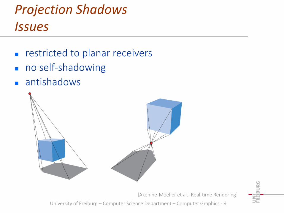
Projection ShadowsIssues
restricted to planar receivers
no self-shadowing
antishadows
[Akenine-Moeller et al.: Real-time Rendering]

University of Freiburg – Computer Science Department – Computer Graphics - 10
Outline
introduction
projection shadows
shadow maps
shadow volumes
conclusion

University of Freiburg – Computer Science Department – Computer Graphics - 11
Concept
see shadow casting as a visibility problem
scene points are visible from the light source (illuminated)
invisible from the light source (in shadow)
resolving visibility is standard functionalityin the rendering pipeline (z-buffer algorithm) frame
buffer
A
B
camera
light
C

University of Freiburg – Computer Science Department – Computer Graphics - 12
Algorithm
render scene from the light source
store all distances to visible (illuminated) scene points in a shadow map
render scene from the camera
compare the distance of rendered scene points to the light with stored values in the shadow map
if both distances are equal, the rendered scene point is illuminated
framebuffer
A
B
camera
light
C
za=za*
zb>zc*zc*
zshadowmap

University of Freiburg – Computer Science Department – Computer Graphics - 13
Coordinate Systems
in the second rendering pass, for each fragment, its position in the shadow map has to be determined convert the 3D position of a
fragment to object space apply modelview transform
of the light L-1M apply projective transform
of the light Plight
homogenization and screen mapping
mapping to texture space results in (x', y', z', 1)T
z' > shadowMap (x', y') point in shadow
cameraspace
objectspace
worldspace
lightspace
V
M
L
V-1
M-1
L-1

University of Freiburg – Computer Science Department – Computer Graphics - 14
Shadow Map Generation
scene is rendered from theposition of the light source
[Akenine-Moeller et al.: Real-time Rendering]
shadow map. a texture that represents distances of illuminatedsurface points to the light source.

University of Freiburg – Computer Science Department – Computer Graphics - 15
Scene Rendering
[Akenine-Moeller et al.: Real-time Rendering]
in a second rendering pass, thecamera view is generated. For each fragment, it is tested whetherit is represented in the shadow mapor not.
in the second rendering pass, va and vb
are rendered. va is represented in theshadow map (illuminated). vb is occludedand not represented in the shadow map(in shadow).

University of Freiburg – Computer Science Department – Computer Graphics - 16
Algorithm
use two depth buffers the “usual” depth buffer for the view point
a second depth buffer for the light position (shadow map)
render the scene from the light position into the shadow map
render the scene from the view position into the depth buffer transform depth buffer values to shadow map values
compare transformed depth buffer values and shadow map values to decide whether a fragment is shadowed or not

University of Freiburg – Computer Science Department – Computer Graphics - 17
Aliasing
discretized representation of depth values can causean erroneous classification of scene points
offset of shadow map values reduces aliasing artifacts
no offset correct offset
[Mark J. Kilgard]

University of Freiburg – Computer Science Department – Computer Graphics - 18
Sampling
in large scenes, sampling artifacts can occur
uniform sampling of the shadow map can result in non-uniform resolution for shadows in a scene
shadow map resolution tends to be too coarse for nearby objects and too high for distant objects
block artifacts
[Stamminger, Drettakis]

University of Freiburg – Computer Science Department – Computer Graphics - 19
SamplingPerspective Shadow Maps
scene and light are transformed using the projective transformation of the camera
compute the shadow map in post-perspective space
[Stamminger, Drettakis]

University of Freiburg – Computer Science Department – Computer Graphics - 20
SamplingPerspective Shadow Maps
uniform shadow map
perspective shadow map [Stamminger, Drettakis]

University of Freiburg – Computer Science Department – Computer Graphics - 21
Summary
image-space technique with two rendering passes
no knowledge of the scene geometry is required
works best for distant spot light sources
light looks at the scene through a single view frustum scene geometry outside the view frustum is not handled
aliasing artifacts and sampling issues

University of Freiburg – Computer Science Department – Computer Graphics - 22
Outline
introduction
projection shadows
shadow maps
shadow volumes
conclusion

University of Freiburg – Computer Science Department – Computer Graphics - 23
Concept
employ a polygonal representation of the shadow volume
point-in-volume test
light
occluder
shadowvolume
camera
receiver
A
A is illuminated,ray does not intersectthe shadow volume
B
B is in shadow,ray enters the shadow volume
C
C is illuminated,ray enters andleaves the shadow volume

University of Freiburg – Computer Science Department – Computer Graphics - 24
Implementation Issues
classification of shadow volume polygons into front and back faces rays enter the volume at front faces / leave it at back faces
stencil buffer values count the number of intersected front and back faces
light
camera
frontface
backface
stencil+=1
stencil-=1

University of Freiburg – Computer Science Department – Computer Graphics - 25
Algorithm (Z-pass)
render scene to initialize depth buffer depth values indicate the closest visible fragment
stencil enter / leave counting approach render shadow volume twice using face culling
render front faces and increment stencil when depth test passes (count occluding front faces)
render back faces and decrement stencil when depth test passes (count occluding back faces)
do not update depth and color
finally, if pixel is in shadow, stencil is non-zero
if pixel is illuminated, stencil is zero

University of Freiburg – Computer Science Department – Computer Graphics - 26
Implementation
render the scene with only ambient lighting
render front facing shadow volume polygons(without depth and color update)to determine how many front face polygons are in front of the depth buffer pixels
render back facing shadow volume polygons(without depth and color update)to determine how many back face polygons are in front of the depth buffer pixels
render the scene with full shading where stencil is zero

University of Freiburg – Computer Science Department – Computer Graphics - 27
Example
occluder
light
camera
0
0
+1
+1
+2 +2
+3
illuminatedpoint
+ ---+ +
stencil value = +1+1+1-1-1-1 = 0

University of Freiburg – Computer Science Department – Computer Graphics - 28
Example
0
0
+1
+1
+2 +2
+3
point in shadow
+ -+ +
stencil value = +1+1+1-1 = 2
occluder
light
camera

University of Freiburg – Computer Science Department – Computer Graphics - 29
Example
zero
zero
+1
+1
+2 +2
+3
illuminatedpoint
stencil value = 0
occluder
light
camera

University of Freiburg – Computer Science Department – Computer Graphics - 30
Example
rendered scene
stencil value = 1stencil value = 0
stencil buffer
light source
occluder

University of Freiburg – Computer Science Department – Computer Graphics - 31
Missed Intersections
0
0
+1+1
+2
+2
+3
nearplane
far plane
Missed shadow volume intersection due to near plane clipping

University of Freiburg – Computer Science Department – Computer Graphics - 32
Solutions
Z-fail counts the difference of
occluded front and back faces
misses intersections behind the far plane
Z-fail with depth clamping do not clip primitives at the far plane
clamp the actual depth value to the far plane
Z-fail with far plane at infinity adapt the perspective projection matrix

University of Freiburg – Computer Science Department – Computer Graphics - 33
Algorithm (Z-fail)
render scene to initialize depth buffer depth values indicate the closest visible fragment
stencil enter / leave counting approach render shadow volume twice using face culling
render back faces and increment stencil when depth test fails (count occluded back faces)
render front faces and decrement stencil when depth test fails (count occluded front faces)
do not update depth and color
finally, if pixel is in shadow, stencil is non-zero
if pixel is illuminated, stencil is zero

University of Freiburg – Computer Science Department – Computer Graphics - 34
Improving Z-fail
depth clamping do not clip primitives to the far plane
draw primitives with a maximum depth value instead(clamp the actual depth value to the far plane)
extend the shadow volume to infinity
set the far plane to infinity (matrices in OpenGL form with negated values for n and f)

University of Freiburg – Computer Science Department – Computer Graphics - 35
Outline
introduction
projection shadows
shadow maps
shadow volumes
conclusion

University of Freiburg – Computer Science Department – Computer Graphics - 36
Summary
projection shadows restricted to planar receivers, no self-shadowing
shadow maps image-space technique, two rendering passes
works correct, if all relevant objects are "seen" by the light
sampling issues
shadow volumes requires a polygonal representation of the shadow volume
multiple rendering passes
clipping of shadow volume polygons has to be addressed

University of Freiburg – Computer Science Department – Computer Graphics - 37
References
Shadow Maps
Williams, "Casting Curved Shadows on Curved Surfaces", SIGGRAPH, 1978.
Brabec, Annen, Seidel, "Practical Shadow Mapping", Journal of Graphics Tools, 2002.
Stamminger, Drettakis, "Perspective Shadow Maps", SIGGRAPH, 2002.
Wimmer, Scherzer, Purgathofer, "Light Space Perspective Shadow Maps", Eurographics Symposium on Rendering, 2004.
Shadow Volumes
Crow, "Shadow Algorithms for Computer Graphics", SIGGRAPH, 1977.
Heidmann, "Real Shadows, Real Time", Iris Universe, 1991.
Diefenbach, "Multi-pass Pipeline Rendering: Interaction and Realism through Hardware Provisions", PhD thesis, University of Pennsylvania, 1996.
McGuire, Hughes, Egan, Kilgard, Everitt, "Fast, Practical and Robust Shadows", Technical Report, NVIDIA, 2003.


![Alias-Free Shadow Maps - NVIDIA Research Homepageresearch.nvidia.com/.../files/pubs/2004-06_Alias-Free-Shadow-Maps/... · Alias-Free Shadow Maps ... I.3.7 [Computer Graphics]: Three-Dimensional](https://img.pdfslide.us/doc/110x75/5aa5dbc37f8b9ae7438e123a/alias-free-shadow-maps-nvidia-research-shadow-maps-i37-computer-graphics.jpg)