Embed Size (px)
Citation preview
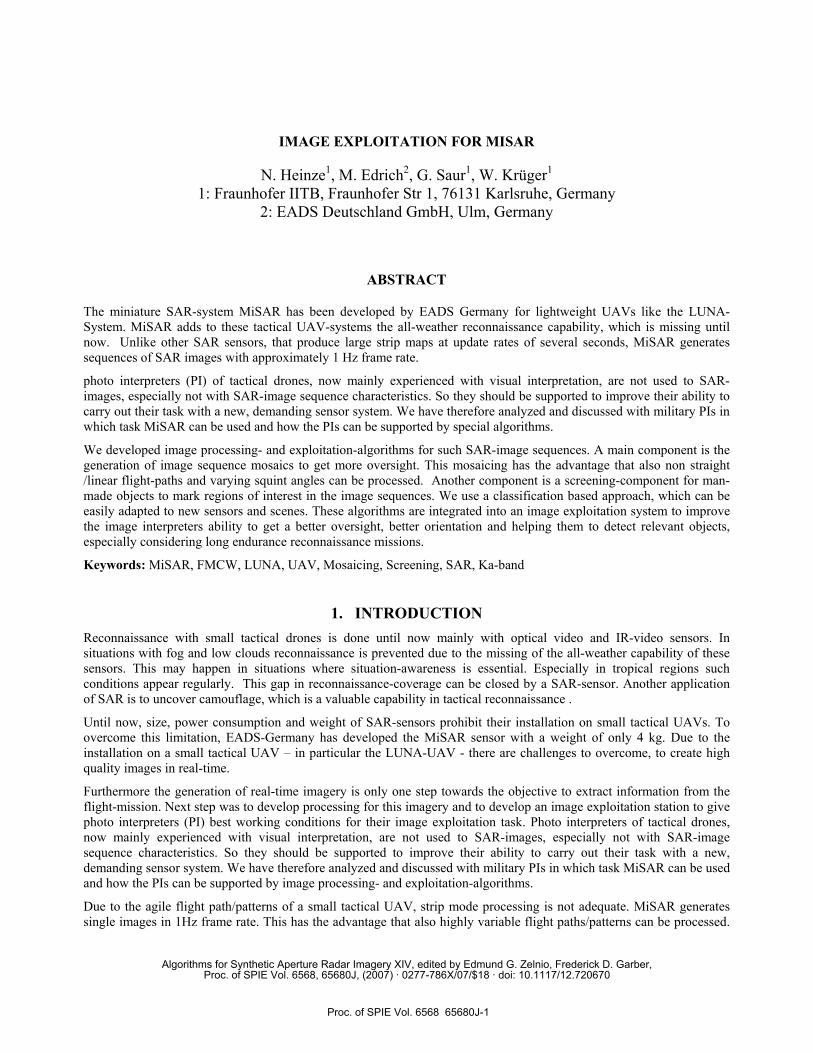
IMAGE EXPLOITATION FOR MISAR
N. Heinze1, M. Edrich2, G. Saur1, W. Krüger1 1: Fraunhofer IITB, Fraunhofer Str 1, 76131 Karlsruhe, Germany
2: EADS Deutschland GmbH, Ulm, Germany
ABSTRACT
The miniature SAR-system MiSAR has been developed by EADS Germany for lightweight UAVs like the LUNA-System. MiSAR adds to these tactical UAV-systems the all-weather reconnaissance capability, which is missing until now. Unlike other SAR sensors, that produce large strip maps at update rates of several seconds, MiSAR generates sequences of SAR images with approximately 1 Hz frame rate.
photo interpreters (PI) of tactical drones, now mainly experienced with visual interpretation, are not used to SAR-images, especially not with SAR-image sequence characteristics. So they should be supported to improve their ability to carry out their task with a new, demanding sensor system. We have therefore analyzed and discussed with military PIs in which task MiSAR can be used and how the PIs can be supported by special algorithms.
We developed image processing- and exploitation-algorithms for such SAR-image sequences. A main component is the generation of image sequence mosaics to get more oversight. This mosaicing has the advantage that also non straight /linear flight-paths and varying squint angles can be processed. Another component is a screening-component for man-made objects to mark regions of interest in the image sequences. We use a classification based approach, which can be easily adapted to new sensors and scenes. These algorithms are integrated into an image exploitation system to improve the image interpreters ability to get a better oversight, better orientation and helping them to detect relevant objects, especially considering long endurance reconnaissance missions.
Keywords: MiSAR, FMCW, LUNA, UAV, Mosaicing, Screening, SAR, Ka-band
1. INTRODUCTION Reconnaissance with small tactical drones is done until now mainly with optical video and IR-video sensors. In situations with fog and low clouds reconnaissance is prevented due to the missing of the all-weather capability of these sensors. This may happen in situations where situation-awareness is essential. Especially in tropical regions such conditions appear regularly. This gap in reconnaissance-coverage can be closed by a SAR-sensor. Another application of SAR is to uncover camouflage, which is a valuable capability in tactical reconnaissance .
Until now, size, power consumption and weight of SAR-sensors prohibit their installation on small tactical UAVs. To overcome this limitation, EADS-Germany has developed the MiSAR sensor with a weight of only 4 kg. Due to the installation on a small tactical UAV – in particular the LUNA-UAV - there are challenges to overcome, to create high quality images in real-time.
Furthermore the generation of real-time imagery is only one step towards the objective to extract information from the flight-mission. Next step was to develop processing for this imagery and to develop an image exploitation station to give photo interpreters (PI) best working conditions for their image exploitation task. Photo interpreters of tactical drones, now mainly experienced with visual interpretation, are not used to SAR-images, especially not with SAR-image sequence characteristics. So they should be supported to improve their ability to carry out their task with a new, demanding sensor system. We have therefore analyzed and discussed with military PIs in which task MiSAR can be used and how the PIs can be supported by image processing- and exploitation-algorithms.
Due to the agile flight path/patterns of a small tactical UAV, strip mode processing is not adequate. MiSAR generates single images in 1Hz frame rate. This has the advantage that also highly variable flight paths/patterns can be processed.
Algorithms for Synthetic Aperture Radar Imagery XIV, edited by Edmund G. Zelnio, Frederick D. Garber,Proc. of SPIE Vol. 6568, 65680J, (2007) · 0277-786X/07/$18 · doi: 10.1117/12.720670
Proc. of SPIE Vol. 6568 65680J-1
T ti±T
The resulting imagery has the form of an image sequence with its own characteristics. A disadvantage of image sequences is the small coverage of each individual frame. To overcome this, we use a mosaicing algorithm, which was initially developed to process video-imagery and was adapted to the characteristics of MiSAR-imagery. The generation of mosaics is based on the extraction of image features from successive images and matching of these features. From the matched features the transformation can be estimated and the mosaic can be generated.
Furthermore a screening algorithm for detecting man-made objects is integrated in our exploitation system. Other methods like along track stereo and stabilized SAR-Video are covered by this paper.
2. MiSAR-SENSOR The overall goal was to design a miniaturized SAR sensor which can be integrated even in small UAVs currently operated on a regular basis. The image resolution and swath should be comparable to the respective capabilities of electro optical sensors used in small UAVs [1]. To transmit the SAR data to the UAV ground control station, the standard analogue video data links used for the E/O sensors should be usable. With these preconditions, the design goals were determined as shown in table 1. The following sections describe the design considerations leading to the MiSAR system concept.
Carrier platforms small size UAVs
Image resolution ∼ 0.5m x 0.5m
Swath 500m ... 1000m
max. onboard weight 4kg
max. onboard volume 10 liter
max. onboard power demand 100W
data link type analogue
data link bandwidth 5MHz
Table 1: Design goals for the MiSAR sensor system
Fig. 1: right: MiSAR, weight: 4kg, volume: < 10 l, power consumption < 100 W, right: Luna with MiSAR
Proc. of SPIE Vol. 6568 65680J-2

2.1 Radar Range
The MiSAR-antenna depression angle φ was chosen to φ =18°... 30°. This range of values provides a good compromise between the three goals of preserving a significant object shadow length for image evaluation purposes, maximising the shadow-free area and minimising resolution deterioration. Considering typical small-UAV flight altitudes of h < 1800m, the maximum radar range can thus be limited to rmax < 4km.
2.2 Radar Principle
Basically, a pulse-doppler (PD) and a FMCW (Frequency Modulated Continuous Wave) concept are potential candidates for the radar frontend. Based on EADS‘ experience in similar applications [4], a FMCW system has clear advantages over the PD system when it comes to size, weight and power considerations. A PD system typically requires a high peak transmission power, which in turn leads to comparatively heavy power amplifiers and power supplies as well as to a higher over-all power consumption. In contrast, the FMCW system operates with a constant low transmission power which can be generated by highly integrated solid-state power amplifiers on MMIC basis. Furthermore, the PD system requires a higher-rate signal processing as compared to the FMCW system, which can reduce its raw data bandwidth drastically by the deramp-on-receive operation [5]. This again leads to lower weight and less power consumption for the FMCW system. However, this is only true if the inherent problems of FMCW systems can be solved [2, 4]: Ensuring sufficient transmitter-receiver isolation and frequency ramp linearity for the envisaged range of 4km is a challenge that requires a solid technology basis and long-term experience in this area [3].
2.3 Selection of Frequency Band
For a highly miniaturised UAV SAR, Ka-band was found to be the optimum choice. Ka-band signals are subject to higher atmospheric and precipitation losses as compared to Ku-band and X-band signals. However, at the given maximum radar range, see section 2.2, these losses are still moderate and can be accounted for in the radar system power budget. Clear advantages of the Ka-band are the good perceptibility of man-made objects in the SAR images, the motion compensation relaxation for a given cross-range resolution and the potential for component miniaturisation at these high frequencies.
2.4 Partitioning of the Image Chain
Fig. 2 shows the typical SAR image chain. The radar front-end consists of the waveform generator, transmitter, antenna system and receiver. In a FMCW radar with a deramp-on-receive concept, the radar raw data at the output of the receiver is an analogue signal with a bandwidth of several MHz. This signal is sampled and digitally processed in the following SAR processor unit. At the output of the SAR-processor unit, SAR images are available to be displayed on a display unit or to be fed into an optional image processor unit with an ATR (Automated Target Recognition) function to assist the operator in the image exploitation process. In the UAV SAR application, this image chain has to be split up in an onboard segment and a ground-based segment. Whereas the radar front-end clearly has to be air-borne and the display unit must be on the ground, the SAR processor unit and the optional image processor unit can be either onboard or on the ground. To minimize onboard size, weight and power for the SAR sensor, it is advantageous to do the digital processing in the ground segment. However, the overall radar systems design has to account for the bandwidth and signal dynamics constraints given by the UAV legacy data link systems as mentioned in table 1.
trans-mitter
antenna control
receiver
waveformgenerator
A SAR
processor
image
processor
display unit
Radar Frontend Digital Processing Unit
D
Fig. 2: SAR image chain
Proc. of SPIE Vol. 6568 65680J-3
//n fT
3. IMAGE GENERATION AND CHARACTERISTICS The images delivered from the SAR processor have the following characteristics:
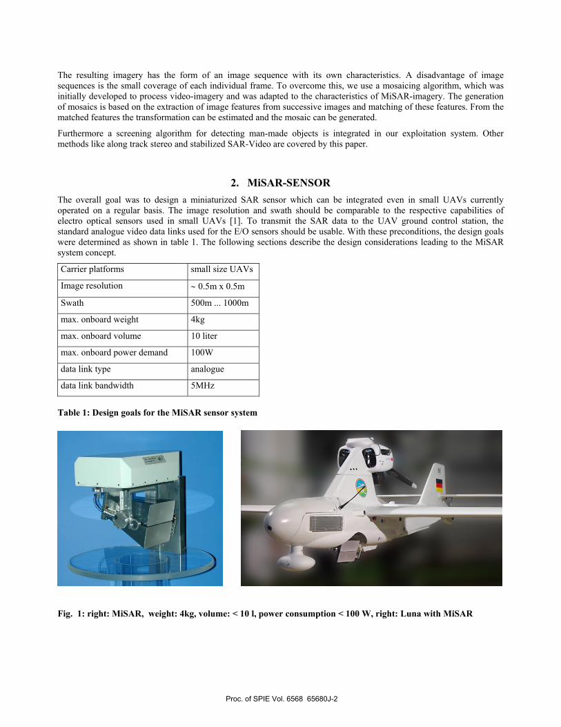
- Coverage of about 400 (azimuth) x 700 (range) meters. The area is a trapezoid with less width in near range than in far range. The angle of the mid axes depends on the squint angle which can vary within the flight (see Fig. 3).
- The radar incidence angle (off nadir) varies from 68° in near range to 76° in far range.
- At a speed of up to 40 meter/second and a frame rate of 1 Hz, consecutive images will have an overlap of approximately 90 %.
- The MiSAR image frames have a gray value range that is coded by 16bit.
- For each image frame, some collateral data carry information about the SAR parameters, the imaging geometry and the flight path (see Fig. 3).
Thus, the image sequences have the characteristics of a “SAR video” of 1 Hz and so we applied some video-like processing to these data.
Fig. 3: Single MiSAR image (left) with trapezoidal coverage (yellow lines) and squint direction (magenta line) and a flight track (red), with line of sights (orange) and some corresponding SAR images over map background Image pre-processing is done in an initial step for displaying purposes and before applying further algorithms (e. g. mosaicing). This includes some filter and a gray value scaling, so that consecutive MiSAR images have the same gray value characteristics. This is essential, since due to the different variations e.g. in the scene, the aspect angle, the squint angle etc. the images must have a uniform gray scaling, so that the mosaicing result has no “gray steps”.
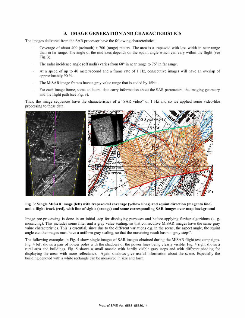
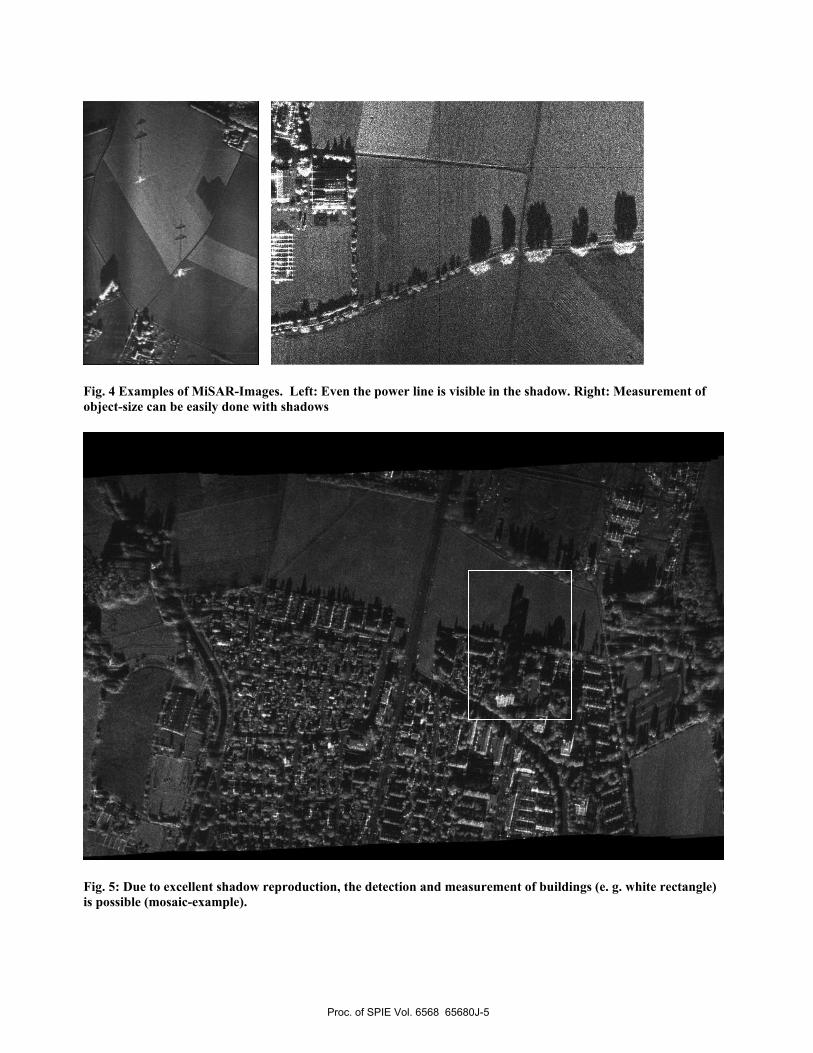
The following examples in Fig. 4 show single images of SAR images obtained during the MiSAR flight test campaigns. Fig. 4 left shows a pair of power poles with the shadows of the power lines being clearly visible. Fig. 4 right shows a rural area and buildings. Fig. 5 shows a small mosaic with hardly visible gray steps and with different shading for displaying the areas with more reflectance. Again shadows give useful information about the scene. Especially the building denoted with a white rectangle can be measured in size and form.
Proc. of SPIE Vol. 6568 65680J-4
,'fr
::.
Fig. 4 Examples of MiSAR-Images. Left: Even the power line is visible in the shadow. Right: Measurement of object-size can be easily done with shadows
Fig. 5: Due to excellent shadow reproduction, the detection and measurement of buildings (e. g. white rectangle) is possible (mosaic-example).
Proc. of SPIE Vol. 6568 65680J-5
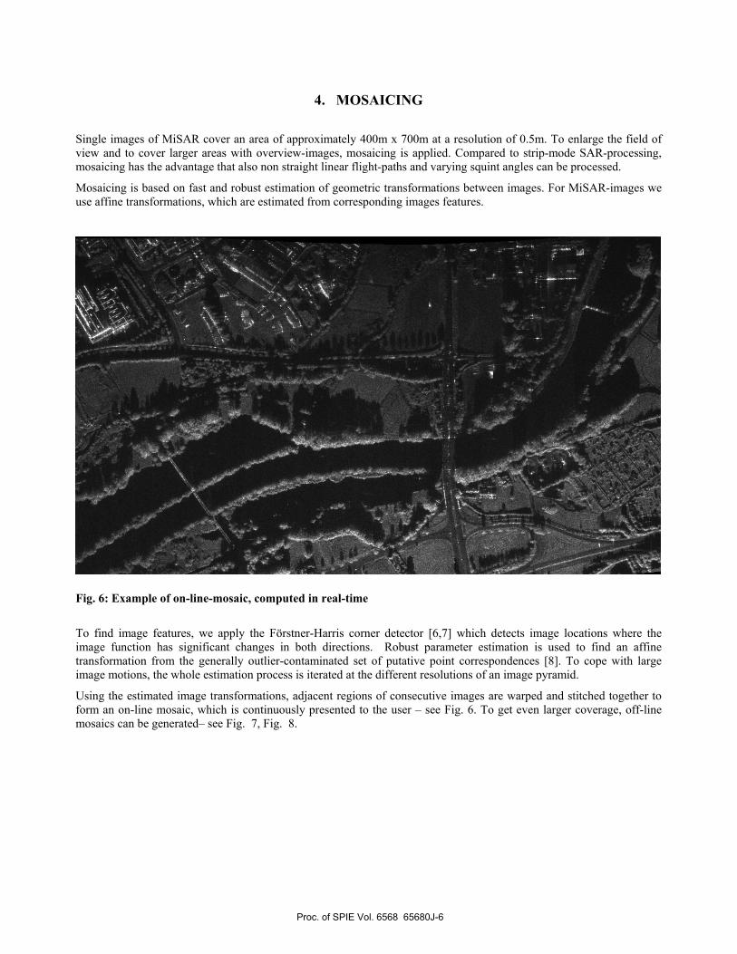
4. MOSAICING Single images of MiSAR cover an area of approximately 400m x 700m at a resolution of 0.5m. To enlarge the field of view and to cover larger areas with overview-images, mosaicing is applied. Compared to strip-mode SAR-processing, mosaicing has the advantage that also non straight linear flight-paths and varying squint angles can be processed.
Mosaicing is based on fast and robust estimation of geometric transformations between images. For MiSAR-images we use affine transformations, which are estimated from corresponding images features.
Fig. 6: Example of on-line-mosaic, computed in real-time
To find image features, we apply the Förstner-Harris corner detector [6,7] which detects image locations where the image function has significant changes in both directions. Robust parameter estimation is used to find an affine transformation from the generally outlier-contaminated set of putative point correspondences [8]. To cope with large image motions, the whole estimation process is iterated at the different resolutions of an image pyramid.
Using the estimated image transformations, adjacent regions of consecutive images are warped and stitched together to form an on-line mosaic, which is continuously presented to the user – see Fig. 6. To get even larger coverage, off-line mosaics can be generated– see Fig. 7, Fig. 8.
Proc. of SPIE Vol. 6568 65680J-6
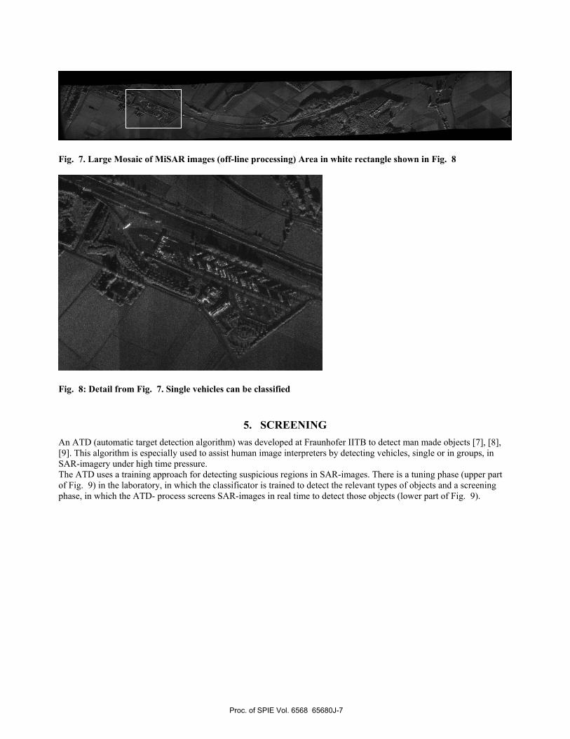
Fig. 7. Large Mosaic of MiSAR images (off-line processing) Area in white rectangle shown in Fig. 8
Fig. 8: Detail from Fig. 7. Single vehicles can be classified
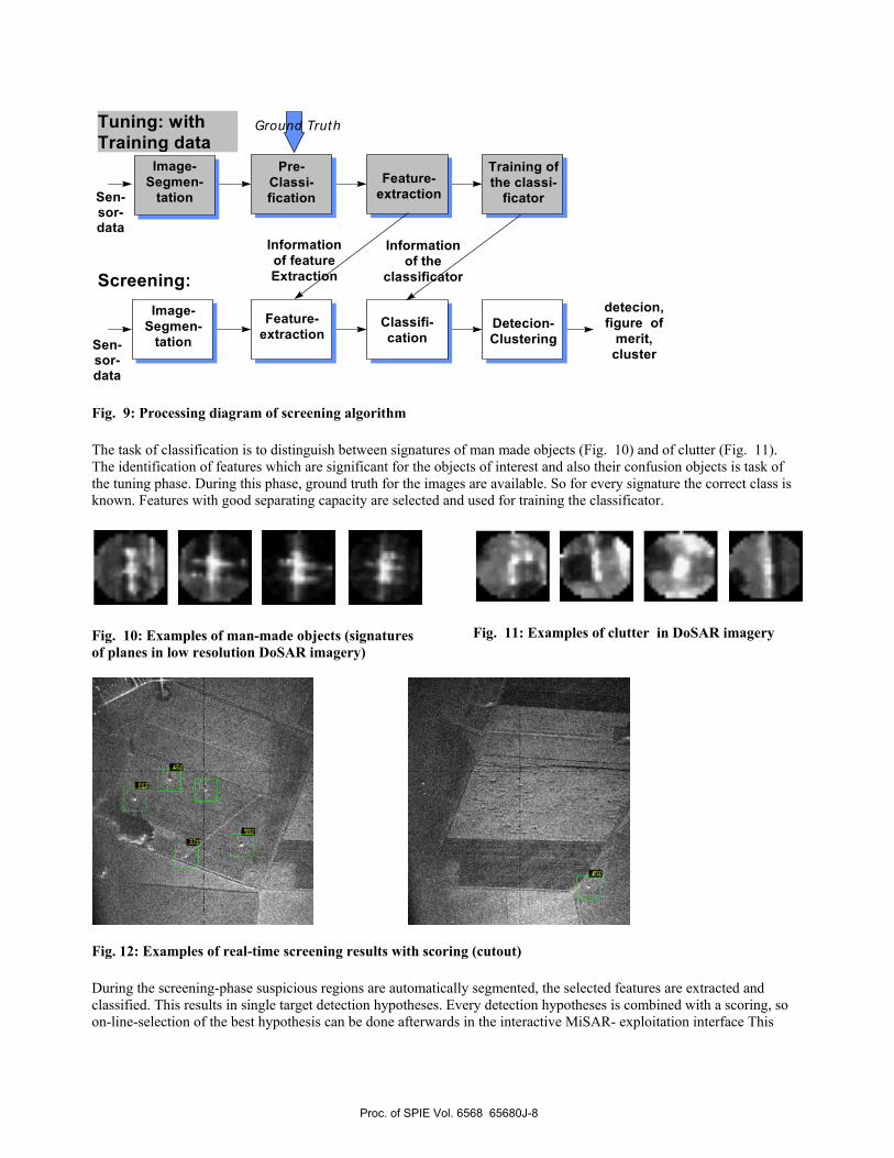
5. SCREENING An ATD (automatic target detection algorithm) was developed at Fraunhofer IITB to detect man made objects [7], [8], [9]. This algorithm is especially used to assist human image interpreters by detecting vehicles, single or in groups, in SAR-imagery under high time pressure. The ATD uses a training approach for detecting suspicious regions in SAR-images. There is a tuning phase (upper part of Fig. 9) in the laboratory, in which the classificator is trained to detect the relevant types of objects and a screening phase, in which the ATD- process screens SAR-images in real time to detect those objects (lower part of Fig. 9).
Proc. of SPIE Vol. 6568 65680J-7
Tuning: with Training data
Pre- Classi- fication
Feature- extraction
Training of the classi-
ficator
Image- Segmen-
tation Classifi-cation
Feature- extraction
Image- Segmen-
tation
Screening:
Detecion- Clustering
Information of feature Extraction
Information of the
classificator
detecion, figure of
merit, cluster
Sen- sor- data
Ground Truth
Sen- sor- data
Fig. 9: Processing diagram of screening algorithm The task of classification is to distinguish between signatures of man made objects (Fig. 10) and of clutter (Fig. 11). The identification of features which are significant for the objects of interest and also their confusion objects is task of the tuning phase. During this phase, ground truth for the images are available. So for every signature the correct class is known. Features with good separating capacity are selected and used for training the classificator.
Fig. 10: Examples of man-made objects (signatures of planes in low resolution DoSAR imagery)
Fig. 11: Examples of clutter in DoSAR imagery
Fig. 12: Examples of real-time screening results with scoring (cutout) During the screening-phase suspicious regions are automatically segmented, the selected features are extracted and classified. This results in single target detection hypotheses. Every detection hypotheses is combined with a scoring, so on-line-selection of the best hypothesis can be done afterwards in the interactive MiSAR- exploitation interface This
Proc. of SPIE Vol. 6568 65680J-8
scoring-value is a measure of the similarity of the extracted signatures compared to signatures presented during the tuning phase – see Fig. 9. By using this scoring as threshold, the PI can adapt the Receiver Operation Characteristic (ROC) to his own preference. A further clustering step prevents that clusters of man made objects generate more than one detection annotation. The ATD and the integration in an human machine interface was approved by elaborate assessments with military PIs see [12].
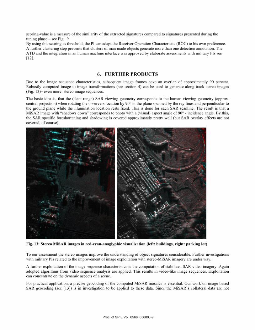
6. FURTHER PRODUCTS Due to the image sequence characteristics, subsequent image frames have an overlap of approximately 90 percent. Robustly computed image to image transformations (see section 4) can be used to generate along track stereo images (Fig. 13)– even more: stereo image sequences.
The basic idea is, that the (slant range) SAR viewing geometry corresponds to the human viewing geometry (approx. central projection) when rotating the observers location by 90° in the plane spanned by the ray lines and perpendicular to the ground plane while the illumination location rests fixed. This is done for each SAR scanline. The result is that a MiSAR image with “shadows down” corresponds to photo with a (visual) aspect angle of 90° - incidence angle. By this, the SAR specific foreshortening and shadowing is covered approximately pretty well (but SAR overlay effects are not covered, of course).
Fig. 13: Stereo MiSAR images in red-cyan-anaglyphic visualization (left: buildings, right: parking lot) To our assessment the stereo images improve the understanding of object signatures considerable. Further investigations with military PIs related to the improvement of image exploitation with stereo-MiSAR imagery are under way.
A further exploitation of the image sequence characteristics is the computation of stabilized SAR-video imagery. Again adopted algorithms from video sequence analysis are applied. This results in video-like image sequences. Exploitation can concentrate on the dynamic aspects of a scene.
For practical application, a precise geocoding of the computed MiSAR mosaics is essential. Our work on image based SAR geocoding (see [13]) is in investigation to be applied to these data. Since the MiSAR`s collateral data are not
Proc. of SPIE Vol. 6568 65680J-9
I - IirI r I— II— - -- I I ]
- - • N 1 nj If ——- N e_I —• •;_js I •_ _a__J -
accurate enough to create the mosaics without looking at the images, these data are not accurate enough for correct geopositioning, too. In our approach, the extracted image structures are matched to the structures given by a geocoded vector map or extracted from a geocoded second image. The resulting transformation delivers the georeference of the MiSAR mosaic.
7. GROUND SEGMENT The ground segment is entirely made up of commercial 19‘‘ rack-mounted PC components. For the image formation part the intrinsic SAR processor unit is a workstation which is linked by a gigabit ethernet switch to two peripheral workstations for data preprocessing and data storage. The exploitation station part are two rack-mounted PCs used for Human-Machine interface, visualization and running of automatic image processing and exploitation algorithms.
The interface to the UAV datalink is given by a standard PCI A/D converter card. For SAR image display, a CRT display with a maximum resolution of 2048x1536 pixels is used. The analogue radar raw data of the onboard radar frontend is transmitted via the standard video link from the UAV to the ground segment. Hence, the radar design parameters were chosen to keep the raw data bandwidth well below the datalink bandwidth. Allocation data, i.e. GPS and motion sensor information as well as sensor status data is transmitted to the ground together with the radar data by a special frequency multiplexing scheme. SAR processing is essentially based on a range-doppler algorithm. Antenna stabilisation and motion compensation have shown to be extremely critical in the small-UAV environment and can be implemented based on measured motion data from an INS system. In the SAR processor, the INS-based motion compensation can be assisted by an autofocus approach, thereby relaxing the accuracy requirements for the motion sensors.
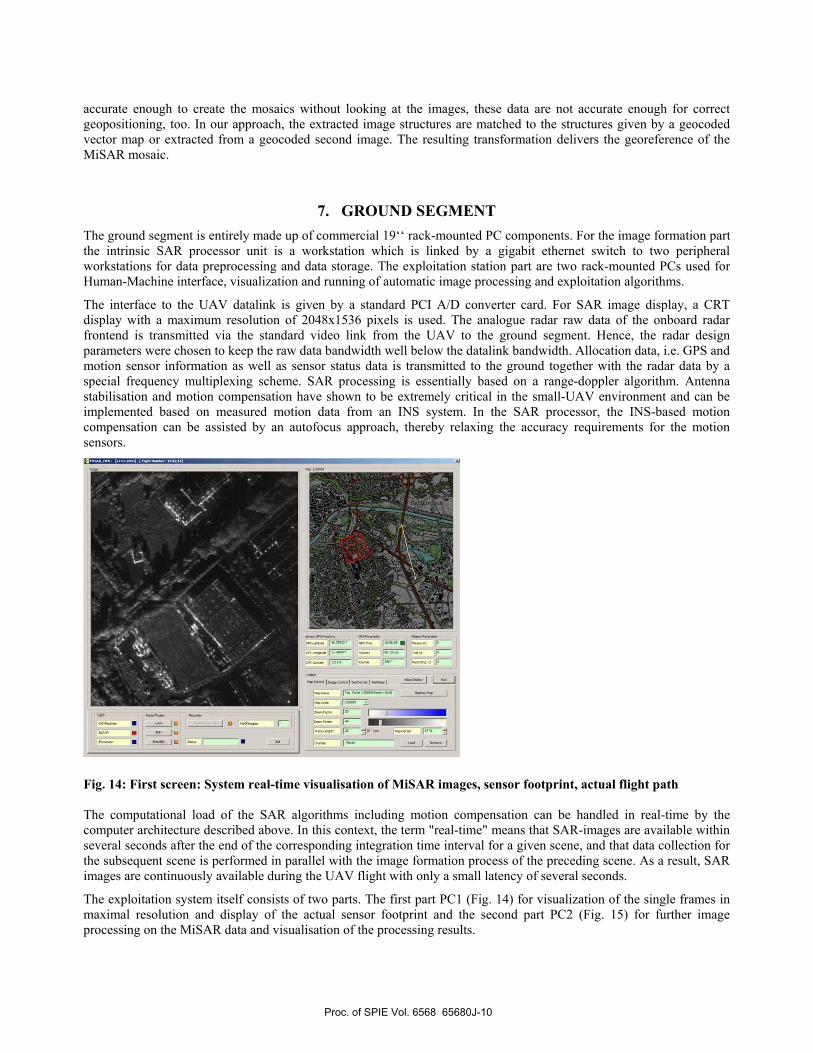
Fig. 14: First screen: System real-time visualisation of MiSAR images, sensor footprint, actual flight path The computational load of the SAR algorithms including motion compensation can be handled in real-time by the computer architecture described above. In this context, the term "real-time" means that SAR-images are available within several seconds after the end of the corresponding integration time interval for a given scene, and that data collection for the subsequent scene is performed in parallel with the image formation process of the preceding scene. As a result, SAR images are continuously available during the UAV flight with only a small latency of several seconds.
The exploitation system itself consists of two parts. The first part PC1 (Fig. 14) for visualization of the single frames in maximal resolution and display of the actual sensor footprint and the second part PC2 (Fig. 15) for further image processing on the MiSAR data and visualisation of the processing results.
Proc. of SPIE Vol. 6568 65680J-10
4 ___Ifl HT3x
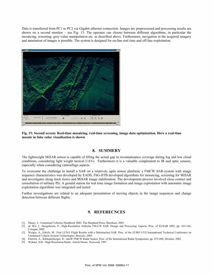
Data is transferred from PC1 to PC2 via Gigabit ethernet connection. Images are preprocessed and processing results are shown on a second monitor – see Fig. 15. The operator can choose between different algorithms, in particular the mosaicing, screening, grey-value manipulation etc. as described above. Furthermore, navigation in the acquired imagery and annotation of images is possible. The system is designed for on-line real time and off-line exploitation.
Fig. 15: Second screen: Real-time mosaicing, real-time screening, image data optimization. Here a real-time mosaic in false color visualisation is shown
8. SUMMERY The lightweight MiSAR sensor is capable of filling the actual gap in reconnaissance coverage during fog and low cloud conditions, considering light weight tactical UAVs. Furthermore it is a valuable complement to IR and optic sensors, especially when considering camouflage aspects.
To overcome the challenge to install a SAR on a relatively agile sensor platform, a FMCW SAR-system with image sequence characteristics was developed by EADS. FhG-IITB developed algorithms for mosaicing, screening for MiSAR and investigates along track stereo and MiSAR image stabilization. The development process involved close contact and consultation of military PIs. A ground station for real time image formation and image exploitation with automatic image exploitation algorithms was integrated and tested.
Further investigations are related to an adequate presentation of moving objects in the image sequences and change detection between different flights.
9. REFERECNCES [1] Masey, J.: Unmanned Vehicles Handbook 2003. The Shephard Press, Burnham, 2003. [2] de Wit, J., Hoogeboom, P.: High-Resolution Airborne FM-CW SAR: Design and Processing Aspects. Proc. of EUSAR 2002, pp. 163-166,
Cologne, 2002. [3] Wergin, A., Edrich, M.: First LUNA Flight Results with a Miniaturised SAR. Proc. of the EURO UVS International Technical Conference on
Unmanned Vehicle System Technologies, Brussels, 2003. [4] Elterich, A., Schmalenberger, R.: mmW FMCW Radar Seeker. Proc. of the International Radar Symposium, pp. 475-480, Dresden, 2003. [5] Wehner, D.R.: High Resolution Radar. Artech House, Norwood, 1987.
Proc. of SPIE Vol. 6568 65680J-11

[6] W. Förstner, E. Gülch. A Fast Operator for Detection and Precise Location of Distinct Points, Corners and Centers of Circular Features. Proc. of the Intercommission Conference on Fast Processing of Photogrammetric Data, Interlaken, Switzerland, 1987, 281-305.
[7] C. Harris, M. Stephens. A combined corner and edge detector. Proc. 4th Alvey Vision Conference, University of Manchester, 31st August - 2nd September 1988, 147-151.
[8] W. Krüger. Robust and efficient map-to-image registration with line segments. Machine Vision and Applications 13 (2001), 30-50. [9] N. Heinze, A. Korn, C.-K. Sung, L. Berger, “Vehicle Classification within the System SAFIR”, in Proceedings of the IAPR TC-7 Workshop
“Remote Sensing and Mapping” Technical University Graz, Austria 2.-3. September, 1996, Editors: F. Leberl, R. Kalliany, M. Gruber, R. Oldenbourg, Wien München 1996, pp. 309-317.
[10] M. Mueller, W. Krueger, N. Heinze, “Model-based target and background characterization“ in Proc. SPIE Vol. 4029, Targets and Backgrounds VI: Characterization, Visualization, and the Detection Process; W. R. Watkins, D. Clement, W. R. Reynolds; Eds. Publication July 2000, pp. 88-92.
[11] M. Mueller, W. Krueger, N. Heinze, “Multisensor data fusion and GIS utilization for ATR“ in Proc. SPIE Vol. 4370, Targets and Backgrounds VII: Characterization and Representation; Wendell R. Watkins, Dieter Clement, William R. Reynolds; Eds. Publication September 2003. pp. 36-41.
[12] A. Berger, R. Eck, N. Heinze, E. Peinsipp-Byma, “Integration of Automatic Detection Algorithms into Interactive Image Interpretation” in Proc. SCI 2004, 8th conference, Vol. 6, July 18-21, 2004 Orlando, Florida, Editors: N. Callaos, W. Lesso, A. Ahmad, pp. 408-413.
[13] G. Saur, W. Krueger , “Fine-geocoding of SAR using robust map-to-image registration”, in Proc. EUSAR 2004, Ulm, Germany, pp. 937-940, VDE 2004
Proc. of SPIE Vol. 6568 65680J-12

Year:2007
Author(s):Heinze, N.; Edrich, M.; Saur, G.; Krüger, W.
Title:Image exploitation for MiSAR
DOI: 10.1117/12.720670 (http://dx.doi.org/10.1117/12.720670)
Copyright 2007 Society of Photo-Optical Instrumentation Engineers. One print or electronic copy may be made for personal use only. Systematic reproduction and distribution, duplication of any material in this paper for a fee or for commercial purposes, or modification of the content of the paper are prohibited.
Details:Zelnio, E.G. ; Society of Photo-Optical Instrumentation Engineers -SPIE-, Bellingham/Wash.:Algorithms for Synthetic Aperture Radar Imagery XIV : Orlando, FL, 10 April 2007Bellingham, WA: SPIE, 2007 (SPIE Proceedings Series 6568)ISBN: 978-0-8194-6690-7Paper 65680J