Embed Size (px)
Citation preview

Image Quality Artifacts in Digital Imaging
Napapong Pongnapang, Ph.D.Department of Radiological Technology
Faculty of Medical TechnologyMahidol University, Bangkok, Thailand
MAHIDOL UNIVERSITYWisdom of the Land

Content
• Image Quality
• Image artifacts
• Types of CR artifacts
• Types of DR artifacts

Image quality
Noise
Contrast Resolution
Modulation Transfer
Function (MTF)
Wiener
Spectra
Contrast-to-
Noise Ratio
(CNR)Contrast-detail Analysis
Rose Model
ROC Analysis
Hasegawa BH, The Physics of Medical X-ray Imaging, 2nd Ed, 1991.

Contrast- The difference in image brightness between
areas in the radiography.
S8
S7
S6
S4
S5
S1
S3
S2

Contrast
%)100(
A
BAC
-OD in screen/film
-Pixel values in DR

Scatter reduces contrast
S S
)(
)()(
SA
SBSAC
SA
BA

Spatial resolution
- The smallest distance that 2 objects can be separated and still appear distinct.
Large focal spot
Small focal spot
Noise
- The uncertainty or imprecision with which a signal is recorded.
5% contrast, 1% noise 5% contrast, 3% noise
s

Quantum Noise
• Although the average number of x-rays interacting in the screen may be constant across the field (a uniform beam).
• The actual number interacting in any given small area will obey a statistical law called the POISSON DISTRIBUTION.
• (doesn’t have to do with quantum mechanics, but with the fact that x-rays come as individual photons or quanta)

The Signal-to-Noise Ratio: A Way to Quantify Noise
If the signal is composed of N photons
and if the noise is given by s = sqrt(N),
then the signal-to-noise ratio is given by
SNR = signal/noise = N/sqrt(N) = sqrt(N)
SNR is the inverse of the fractional noise (noise/signal)Bigger SNR is better (within dose constraints).

Poisson Statistics: Raindrops Analogy
N = 10 40 100s = 3.2 6.3 10 SNR = 3.2 6.3 10
sprinkle shower downpour
low dose medium dose high dose

Contrast-to-Noise Ratio (CNR)- Low contrast detectibility can be directly
related to CNR.
- CNR is proportional to SNR, or square-root of NEQ (Noise equivalent quanta).
s
SCNR
s
S
S
S
SNRC

Modulation Transfer Function (MTF)
- The contrast produced by an imaging system as a function of the spatial frequency of the object or input signal.
=
object psf image
)(mod_
)(mod_)(
uulationInput
uulationOutputuMTF
minmax
minmax
II
IIModulation

Detective Quantum Efficiency (DQE)
- The efficiency for a detector system to use x-ray to generate images with adequate SNR.
2
in
out
SNR
SNRDQE
detectorSNRin SNRout

Artifacts and Digital Systems
• Artifacts are any fault impressions appear on the images
• Digital imaging produces different kinds of artifacts commonly found in conventional screen/film

Artifacts and Digital Systems
• Recognizing artifacts in digital radiograph can avoid misinterpreting those distracting patterns as pathological findings
• Can be generated from users who are not aware of proper imaging techniques or image processing selection

Classification of artifacts in digital imaging
• Hardware
• Software/Image processing
• Image display
• Operator error

Hardware – Image Plate
• Image plate are susceptible for cracking
• Deterioration progress appears from the middle of the plate
• Debris that blocks IP emission of light when scanning with laser will make image appear bright at the site
• Back-scatter can also produce artifacts due to high sensitivity to scatter radiation of the IP

Image plate artifact
Residue from adhesive tape used to attach lead markers tothe outside of the cassette

Image plate artifact
CRACK OF THE IP:
Image shows artifacts appears in anatomical region

Image plate artifact
Static caused a hair to cling to the IP on this skull image.

CR Artifacts
Crack in IP : looks like a foreign body
L J CESAR, et al BJR 74 (2001)

Image plate artifact
Debris from IP crack:
Normally radiologist
can tolerate, sometimes confusing with foreign bodies

Image plate artifact
The dark line along the lateral portion of this upper abdomen is caused
by backscatter transmitted through the back of the cassette.
The line corresponds to the cassette hinge where the lead coating
was weakened or cracked.

How to solve these problems from image plate artifacts
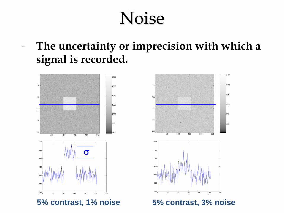
• Clean IP plate regularly
• Refer to vendor’s recommendation regarding methods for cleaning
• Frequency of cleaning depends on the usage

Manufacterer’s recommendation

Manufacturer’s Recommendation
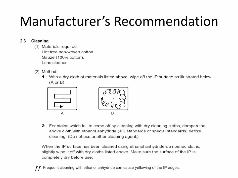
Manufacturer’s Recommendation
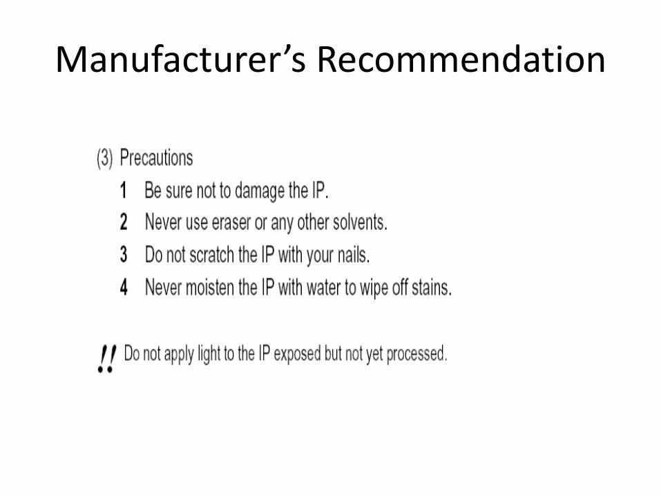
Manufacturer’s Recommendation

Hardware: Image reader
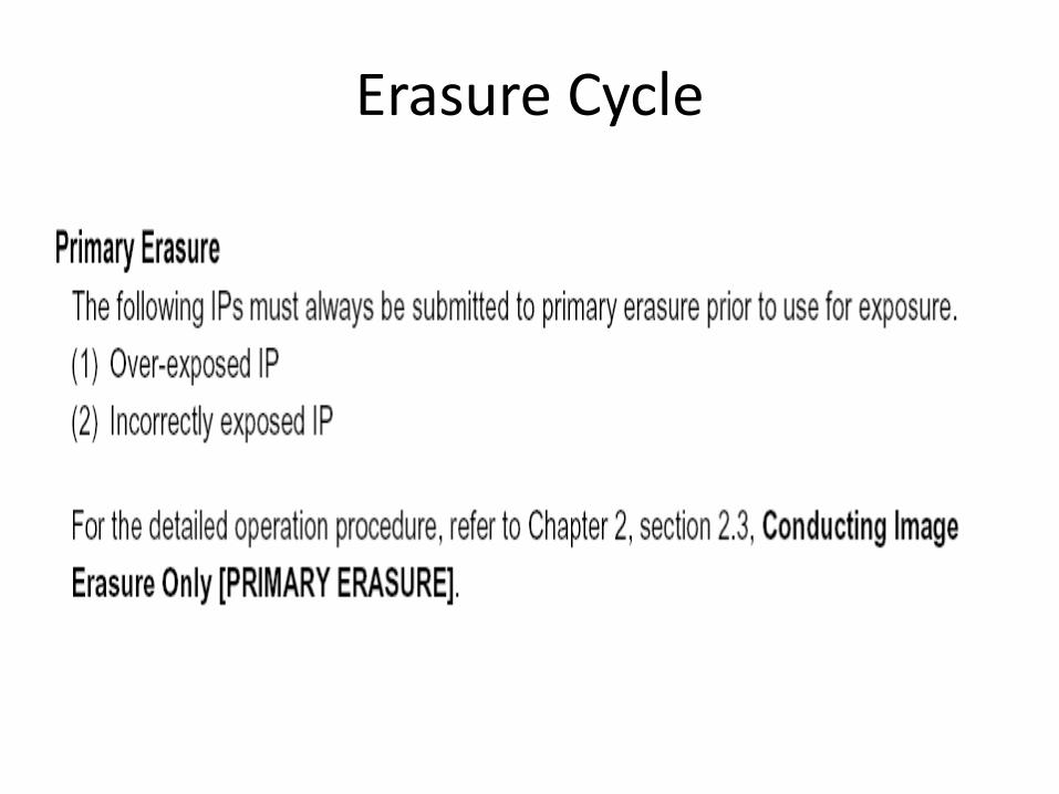
• Normally IPs are automatically reased after used
• IPs must be manually erased after not in use for a period of time
• For incorrect (intense) exposure, IPs should be erased with longer erasure cycle
• Incomplete erasure can produce artifacts

Plate reader artifacts
The electronic board that controlled the photomultiplier tube was malfunctioned.
Call in service engineer

Plate reader artifacts
Dirt on the light-guide cause line artifact

Plate reader artifacts
Plate reader artefact. This artifact occurredbecause the plate reader loaded two imaging plates(IPs) in a single cassette. After an exposure, thebottom IP was extracted, read and replaced as usual,leaving the top IP to be exposed numerous times.Artefact remedy: double-loaded cassettes will be discoveredduring routine IP cleaning. If a cassette containingtwo IPs is discovered, the IPs should beerased before being put back into use.

Plate reader artifacts
Plate reader artefact. This bilateral kneeimage was spoiled when the incorrect erasure settingwas used to eliminate a previous femur image.Evidence of this is the residual image of the leadmarker in the top corner of the image, the tissue linefrom the previous image (upper arrow) and the additionalline of collimation along the bottom of theimage (lower arrow). Artefact remedy: radiographersmust select the correct erasure setting according tothe type of exposure that has occurred.

Erasure Cycle
Erasure Cycle

Image processing
• Proper image processing should be employed to avoid appearance of artifacts
• Keep in mind that we cannot create anything that is not part of the patient
• Image processing cannot correct for everything!

Image processing artifacts

Image processing artifacts
Inadequate image processing Mismatch technique/post processing

Image processing artifacts

Image processing artifacts

Image processing artifacts

Image processing artifacts

Image Display: Laser printer artifact

Operator Error Artifacts
• Radiographers can create artifacts
• Care should be taken when working with CR
• Learning about patterns of artifacts and remedy are encouraged

Operator error

Operator error

Operator error

Operator error

Operator error

Operator error

Other types

Other types

Other types

Other types

Other types

To avoid artifacts in CR
• Aware of cause of artifacts
• Learn about appearance of different artifact types
• Clean your IP
• Make sure service people come in regularly

What about DR?

59
Characteristics of “Direct” capture
systems
+ Rapid acquisition and processing
+ Typically integrated with x-ray generator
+ No mechanical scan mechanism
— High initial capital investment
— Challenging manufacturing processes
— Limited systems for bedside radiography
? Brief history of clinical operation? Life cycle issues unknown
(durability?)? Image rendering unknown? Exposure factor issues
Courtesy JA Seibert, UC-DavisRadiation Protection in Digital Radiology L07 Avoiding Artefacts in Digital Radiography

60
What was the previous view
acquired?
• All DR systems are subject to “ghosting” and/or “lag”– Lag is effective
increase in dark current (offset)
– Ghosting is a change in detector sensitivity (gain)• a-Se = reduction
• CsI(Tl), a-Si:H = increase
Radiation Protection in Digital Radiology L07 Avoiding Artefacts in Digital Radiography

61
Uncorrected DR image is
inherently non-uniform
Radiation Protection in Digital Radiology L07 Avoiding Artefacts in Digital Radiography

62
Non-uniformities are corrected
by
“flat-fielding”
Radiation Protection in Digital Radiology L07 Avoiding Artefacts in Digital Radiography

63
Chest image from a flat
panel obtained at 75 kV
(mistake, using
abdomen protocol).
More entrance dose
and slight saturation
Radiation Protection in Digital Radiology L07 Avoiding Artefacts in Digital Radiography

64
Chest image from a flat
panel obtained at 75 kV
(mistake, using abdomen
protocol).
More entrance dose and
slight saturation
Radiation Protection in Digital Radiology L07 Avoiding Artefacts in Digital Radiography

65
Raw vs. Corrected DR Image
Bushberg, Seibert, Leidholdt, Boone The Essential Physics of Medical Imaging 2nd Ed
Radiation Protection in Digital Radiology L07 Avoiding Artefacts in Digital Radiography

66
Artifacts related to gain and offset correction
Willis CE et al. Appl Radiol. 11-20, 2004
GE DR Canon DR
Radiation Protection in Digital Radiology L07 Avoiding Artefacts in Digital Radiography

67
Composition of image affects
display processing
Default Reprocessed
Radiation Protection in Digital Radiology L07 Avoiding Artefacts in Digital Radiography

68
Gonadal shielding has
drawbacks• Ovary locations vary
• Shield may obscure clinical features
• Shield may interfere with automatic image processing
Processed Unprocessed
Radiation Protection in Digital Radiology L07 Avoiding Artefacts in Digital Radiography

69
Large patient – covers entire
detector
(if there’s no contrast in the raw image, there’s not much image processing can do)
Radiation Protection in Digital Radiology L07 Avoiding Artefacts in Digital Radiography

70
Was there a clinical necessity
for this “appliance”?
Would this have been any
less of an error with
conventional screen-film?
Radiation Protection in Digital Radiology L07 Avoiding Artefacts in Digital Radiography

71
Summary
• DR systems are inherently non-uniform in
two dimensions
– Proper correction of non-uniformity is critical
to DR image quality
– Periodic correction is necessary
• DR systems are subject to lag and
ghosting
• The composition of the DR image affects
the outcome of digital image processing
Radiation Protection in Digital Radiology L07 Avoiding Artefacts in Digital Radiography

References
• Solomon SL, Jost RG, Glazer HS, et al. Artifacts in computed radiography. Am J Roentgenol 1991; 157(1): 181-5.
• Cesar LJ, Schueler BA, Zink FE, et al. Artefacts found in computed radiography. Brit J Radiol 2001; 74(878): 195-202
• N. Pongnapang. Practical guidelines for radiographers to improve computed radiography image quality. Biomed Imaging Interv J 2005; 1(2):e12 5
• IAEA Digital Imaging Training Materials