Embed Size (px)
Citation preview

PROUDLY MADE IN THE
USA
Ce
rtified Company
ISO9001:2008
iMAG 4700p Municipal/Industrial Magmeter
Instructions
iMAG 4700p

IMAG 4700p INSTRUCTIONS
Seametrics • 253.872.0284 Page 2 seametrics.com
TABLE OF CONTENTS
General Information General Information ...................................................................................................................................................Page 3Features ...........................................................................................................................................................................Page 3Specifications ................................................................................................................................................................Page 4Dimensions ....................................................................................................................................................................Page 5Accuracy ..........................................................................................................................................................................Page 6Flow Rate ........................................................................................................................................................................Page 6
Installation Positioning the Meter ..................................................................................................................................................Page 7Equalization and Grounding (Metal and Plastic Pipe) .....................................................................................Page 7Straight Pipe Recommendations ...........................................................................................................................Page 8Full Pipe Recommendations ....................................................................................................................................Page 9
Connections
General Cable Information .......................................................................................................................................Page 10Cable Gland Opening and Sealing ........................................................................................................................Page 10Cable Installation .........................................................................................................................................................Page 11Wiring Diagrams ..........................................................................................................................................................Page 12Cable Wiring Table ......................................................................................................................................................Page 14
ConfigurationSourcing Mode Output Application .....................................................................................................................Page 15Sinking Mode Output Application ........................................................................................................................Page 15Analog (4-20mA Current Loop) Output Application .....................................................................................Page 15Cable Shield ...................................................................................................................................................................Page 16Pulse Output ..................................................................................................................................................................Page 16Analog (4-20mA) Output ..........................................................................................................................................Page 16HART Output .................................................................................................................................................................Page 16Modbus Output............................................................................................................................................................Page 16Digital Output ...............................................................................................................................................................Page 16
OperationChanging Flow Meter Settings - Home Screen and General Navigation ..............................................Page 17Changing Flow Meter Settings - Making Selections ......................................................................................Page 17Changing Flow Meter Settings - Standard Menu Options ..........................................................................Page 18Changing Flow Meter Settings - Special Submenu ........................................................................................Page 18
Troubleshooting Problem ...........................................................................................................................................................................Page 19Probable Cause .............................................................................................................................................................Page 19Things to Try ..................................................................................................................................................................Page 19
Note: These instructions cover the iMAG 4700p For details on the iMAG 4700 or 4700r, see the iMAG 4700 or iMAG 4700r Municipal/Industrial Magmeter Instructions.

IMAG 4700p INSTRUCTIONS
Seametrics • 253.872.0284 Page 3 seametrics.com
GENERAL INFORMATION
The iMAG-Series are the most economical flanged electromagnetic flowmeters on the market. With electrodes designed to discourage fouling, it is available in 4” to 12” pipe in municipal or industrial water, waste and reclaimed water, pump stations, and packaged plant applications. (For 3” version, see iMAG 4600-300.) Minimal straight pipe requirements allow iMAG-Series meters to be used in piping configurations where there is little space between the meter and an elbow.
iMAG-Series meters are NSF-61 approved and are rated IP68 for applications where the meter may be operated underwater to a depth of at least 10 feet (3 meters) continuously.
Both rate and total indication are standard. Rate and total units and pulse scaling can be set via the front panel touch key pad by the user. Bidirectional flow is standard with forward, reverse, and net flow.
A power/output cable allows outputs for use with a variety of Seametrics and other displays and controls for remote reading and telemetry applications. Pulse output and 4-20mA passive current loop are standard on all units. Additionally, HART protocol, high speed digital, and Modbus® protocol outputs are optional. The iMAG 4700p can be supplied with an optional internal AC power supply.
Features
No moving parts!
iMAG 4700p
Welded steel epoxy-coated flow tube
Flanges, 150 lb. ANSI pattern
Santoprene/Polypropylene Liner
Equalization lug
Powder-coated diecast aluminum electronics housing
Rate and total indicator with light sensor button controls
316SS electrodes (Inside)
Power and Output cable port access
User access lid (on back)
Data logger port (right side, not shown)

IMAG 4700p INSTRUCTIONS
Seametrics • 253.872.0284 Page 4 seametrics.com
GENERIAL INFORMATION
Specifications*
Pipe Sizes 4”, 6”, 8”, 10”, 12” (For 3” version, see iMAG 4600-300.)
Flanges 150 lb. ANSI Pattern
Pressure 150 psi (10.3 bar) line pressure
Temperature Operating 10˚ to 130˚ F (-12˚ to 54˚ C)
Storage -40˚ to 158˚ F (-40˚ to 70˚ C)
Accuracy ±0.75% of reading, ±0.025% of full-scale flow from low flow cutoff to maximum flow rate of 10 m/sec
Low Flow Cutoff 0.5% of maximum flow rate
Material Body (4”-12”) Welded steel, epoxy-coated
Liner (4”-12”) Santoprene flange/Polypropylene liner body
Electronics Housing Powder-coated diecast aluminum
Electrodes 316 stainless steel
Display Type 128x64 dot-matrix LCD
Digits 5 Digit Rate 8 Digit Total
Units
Please Note:All iMAG meters are factory set for gallons per minute (GPM) rate and gallons total. If other units are required, they can be set in the field.
Rate Volume Units Rate Time Units Total Volume Units
GallonsLitersBarrels (42 gallons)Cubic FeetCubic MetersMillion Gallons2
Mega LitersImperial Gallons Million Imperial Gallons2
SecondMinuteHourDay
GallonsGallons x 1000Million GallonsLitersKilo LitersMega LitersBarrels (42 gallons)Cubic Meters
Cubic Meters x 1000Cubic FeetCubic Feet x 1000Million Cubic FeetImperial GallonsImperial Gallons x 1000Million Imperial Gallons
Bi-directional1 Forward Total, Reverse Total, Net Total
Power DC Power 9-36 Vdc @ 250 mA max, 30 mA average
AC Power 85-264Vac, 50/60Hz, 0.12A
Backup Battery DC powered units: Two lithium 3.6V ‘D’ batteries, replaceable. AC powered units: Two lithium 3.6V ‘AA’ batteries, replaceable.
Scaled Pulse Output
Signal Current sinking pulse, isolated, 36 Vdc at 10 mA max
Pulse Rates User-scalable from 0.1 to 99,999.9 volume units/pulse. Pulse width is one-half of pulse period with minimum pulse width of 2.5 ms, 200 pulses/sec max
4-20mA Current Loop Isolated, passive, 24Vdc, 650 Ω maximum current loop
Options HART/4-20mA HART protocol over 4-20mA line
High Speed Digital Output
Isolated, open collector, 24 Vdc
Serial Communications
Isolated, asynchronous serial RS485 (Reconfigurable for RS232 or 3.3V CMOS), Modbus® RTU protocol (factory selectable)
Cable Power/Output Cable 20ft (6m) standard length polyurethane jacketed cable—for power and outputs (lengths up to 200’ available).
Conductivity >20 microSiemens/cm
Empty Pipe Detection Hardware/software, conductivity-based
Regulatory (EN 61326) pending, NSF-61
Environmental IP68 (10ft (3m) depth, continuously)
Modbus is a registered trademark of Schneider Electric.* Specifications subject to change. Please consult our website for the most current data (www.seametrics.com).1 If forward and reverse flow data needs to be sent to another device, either the Digital or Modbus output is required.2 Rate Time Unit is available in Day only.

IMAG 4700p INSTRUCTIONS
Seametrics • 253.872.0284 Page 5 seametrics.com
Dimensions
GENERAL INFORMATION
iMAGMeter Size
L H T ID Shipping Weight
Flange Bolt Torque
inch mm inch mm inch mm inch mm lbs Kg ft-lb Nm
4” 10.24 260 8.6 218 .62 15.7 3.12 79 27 12 20 276” 12.27 312 9.4 239 .69 17.5 5.05 128 42 19 42 578” 14.24 362 10.4 264 .69 17.5 6.44 164 64 29 65 88
10” 18.18 462 11.5 292 .69 17.5 8.61 219 120 54.5 73 9912” 19.68 500 12.5 317 .81 20.6 10.55 268 162 73.5 97 132
Remote Display shipped separately 2.75 1.25 n/a n/a
Flanges Standard ANSI 150 lb. drilling Cable 1 lb.REPEAT CROSS-
TIGHTENING PATTERN TO FINAL TORQUE VALUE
H
L
T
ID
Install security seals during installation if regulations require.

IMAG 4700p INSTRUCTIONS
Seametrics • 253.872.0284 Page 6 seametrics.com
Flow Rate (4” - 12”)
Pipe Size (Inches in diameter) 4” 6” 8” 10” 12”
Max Flow Rate (Gallons/Minute) 1285 2891 5140 8031 11565
Cut-off (min) Flow Rate(Gallons/Minute) 6.43 14.46 25.70 40.15 57.82
Max Flow Rate (Liters/Second) 81 182 324 507 730
Cut-off (min) Flow Rate(Liters/Second) 0.41 0.91 1.62 2.54 3.65
Max Flow Velocity (Meters/Second) 10 10 10 10 10
GENERAL INFORMATION
0
1
2
3
4
5
33 0 5 10 15 20 25 30
Acc
urac
y (%
)
Flow Velocity
(m/s)
(ft/s)
0
1
2
3
4
5
5 10 15 20 25 30 330
420 6 8 10
iMAG Accuracy

IMAG 4700p INSTRUCTIONS
Seametrics • 253.872.0284 Page 7 seametrics.com
Equalization and Grounding
Metal Pipe Installations. To equalize the electrical potential of the fluid, the iMAG meter, and the surrounding pipe, secure the flange plates (factory-installed on the equalization wire) to both pipe flanges at one of the bolt holes, as shown below. Be sure the lock washer fits between the pipe flange and the flange plate. For the best electrical bonding, remove rust and paint to expose clean, bare metal where the equalization flange plate lock washer contacts the pipe flange. Connection must be inspected periodically for corrosion to maintain the necessary low resistance connection.
Run wire from equalization lug to both pipe flanges; secure flange plates under bolt heads as shown.
Plastic Pipe Installations. When the iMAG is installed in a plastic piping system, grounding rings may be required, especially in the presence of electrical interference sources such as VFD pump drives. As shown in the diagram below, the equalization wires should then be connected to the grounding ring tabs instead of the flange bolts as in metal piping installations. Where lightning is a threat, or in severe electrical environments, an optional connection to a nearby equipment ground or ground rod may be advisable.
Grounding Ring Part Numbers
4” = 100876 6” = 100877 8” = 100878 10” = 100879 12” = 103288SEAMETRICS
GROUND RING (2X)
FLANGE GASKETSURFACE
O-RING (Not suppliedby Seametrics)
CAUTION: Grounding rings are recommended for installations that could damage the flange gasket.
WARNING: ELECTRICAL SHOCK HAZARD When the meter is externally AC powered, the piping system must be grounded to meet national and local electrical safety codes. Failure to do so can result in electrocution.
Metal Pipe Metal Pipe
Meter Equalization Lug
Flange PlateLockwasher
Meter FlangePipe Flange
Meter Flange
Pipe Flange
#6, #8 or #12 AWG Stranded Copper Ground Wire < 5’
Ground Clamp
8’ Ground RodEarth
Exothermically weld when corrosion is a concern
Meter Equalization Lug
Plastic Pipe
Plastic PipeGrounding
Ring
Positioning the Meter
These meters can be installed horizontally, vertically (with downward flow), and in any radial position. Using a check valve on the upstream side of the meter, and/or an air vent (vacuum relief valve) in the same, unobstructed run of pipe as the meter, is required in any installation where the meter may be exposed to suction when the system is not in normal operation. Suction can cause damage to the liner. Liner damage caused by suction, without the use of a check valve and/or air vent, may void the warranty.
Straight Pipe Recommendations. The iMAG requires straight pipe before and after the meter for best accuracy. However, the ability of electromagnetic meters to average the flow across the entire pipe allows for shorter straight pipe recommendations than most mechanical meters (see page 8).
Full Pipe Recommendations. To prevent false readings, this meter is designed to indicate ‘EMPTY PIPE’ if one or more electrodes is exposed. For highest accuracy, install the meter so that the pipe will be full when there is flow. If air bubbles may be present in the pipe or sludge accumulation is an issue, rotate the meter by one flange hole to position the control housing at a 45˚ angle (see diagrams on page 9).
Fittings. The iMAG has ANSI 150 lb. drilled flanges and will mate with any other ANSI 150 lb. flanges. See table on page 5 for flange bolt tightening torque specifications.
Calibration. The iMAG is factory-calibrated and will not require any form of field calibration.
Chemical Injection. When the iMAG is used in a chemical injection application, the chemical injection point must be placed downstream of the magmeter OR far enough upstream for complete mixing to occur before the fluid reaches the meter. When unmixed chemical alternates with water passing through the meter, the rapid changes in conductivity may cause sudden spikes and drops in the meter’s reading, resulting in inaccurate measurement. The magmeter will restabilize, however, with a steady flow of fluid of uniform conductivity.
CAUTION: These flow sensors are not recommended where installation may expose the flow sensor to boiler pressure and temperature. Maximum recommended operating temperature is 130˚ F.
CAUTION: In chemical injection applications, install chemical injection point downstream of magmeter, or far enough upstream to allow complete mixing of fluids.
INSTALLATION

IMAG 4700p INSTRUCTIONS
Seametrics • 253.872.0284 Page 8 seametrics.com
INSTALLATION
12345
12345
12345
12345
12345
12345
1X2X
2X
2X
1X5X
5X
5X
Reduced Pipe
Two Elbows In Plane
Two Elbows, Out Of Plane
Expanded Pipe
Swirling Flow:
Propeller Meter
Partially OpenButterfly Valve
1X
1X
1X
1X
Swirling Flow:
iMAG
iMAG
iMAG
iMAG
iMAG
iMAG
Straight Pipe Recommendations (X = diameter)

IMAG 4700p INSTRUCTIONS
Seametrics • 253.872.0284 Page 9 seametrics.com
12345 12345
12345
12345
INSTALLATION
Not Ideal:Air bubbles and sediment on the
electrodes can affect accuracy
Intermittent airbubbles
pass overelectrode
Possible sediment build-up
iMAG
Recommended:Improved accuracy results from
unimpeded electrodes
Electrode moved from
top by rotating meter
Intermittent airbubbles
miss electrode
Electrodes free from sediment
build-upiMAG
12345
12345
Not Ideal:Allows air pockets to form at meter
iMAG
Recommended:Keep pipe full at meter for accuracy
iMAG
12345
12345
Not Ideal:Air can be trapped
iMAG
Recommended:Allows air to bleed off
Full Pipe Recommendations
12345 12345
12345
12345
Not Ideal:Post-valve cavitation can create air pocket
Recommended:Keeps pipe full at meter for accuracy
12345 12345
12345
12345
12345 12345
12345
12345
iMAG
iMAG iMAG
IMAG 4700p INSTRUCTIONS
Seametrics • 253.872.0284 Page 10 seametrics.com
CONNECTIONS
General Cable Information
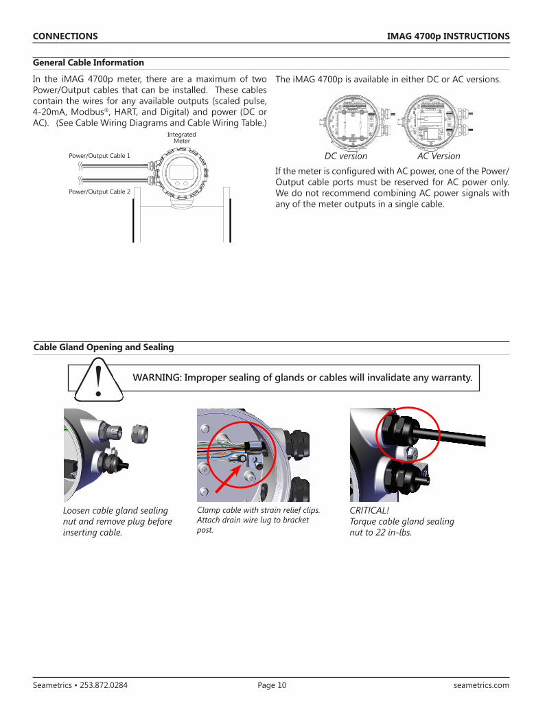
In the iMAG 4700p meter, there are a maximum of two Power/Output cables that can be installed. These cables contain the wires for any available outputs (scaled pulse, 4-20mA, Modbus®, HART, and Digital) and power (DC or AC). (See Cable Wiring Diagrams and Cable Wiring Table.)
Power/Output Cable 2
Power/Output Cable 1
IntegratedMeter
WARNING: Improper sealing of glands or cables will invalidate any warranty.
Cable Gland Opening and Sealing
The iMAG 4700p is available in either DC or AC versions.
DC version AC Version
If the meter is configured with AC power, one of the Power/Output cable ports must be reserved for AC power only. We do not recommend combining AC power signals with any of the meter outputs in a single cable.
CRITICAL! Torque cable gland sealing nut to 22 in-lbs.
Loosen cable gland sealing nut and remove plug before inserting cable.
Clamp cable with strain relief clips. Attach drain wire lug to bracket post.

IMAG 4700p INSTRUCTIONS
Seametrics • 253.872.0284 Page 11 seametrics.com
8. Strip cable jacket and conductors and install 3 conductor power cable and wire to Line (L), Neutral (N) and ground (G) positions on power supply terminal block.
9. Plug the 15 pin screw connector into its socket.10. Plug the backup battery cable into either of
the two connectors to the left of the 15 pin connector. (Standard backup batteries are two 3.6V “D” lithium cells. For the AC option, the backup batteries are two 3.6V “AA” lithium cells.)
11. Secure the cables inside the internal strain relief clip and tighten the cable gland sealing nut securely. (torque nut to 22 in-lbs.). A loose nut could cause moisture ingress and compromise the meter head’s IP68 rating, voiding the warranty.
12. Reinstall the user access lid. Be sure to avoid cross-threading the lid and to not pinch any wires with the lid.
Internal AC wires
15 pin connectorBackup
battery connection
Power supply terminal block (AC versions)
CONNECTIONS
Cable Installation
1. On the back of the meter, unscrew the black user access lid and remove it.
2. Remove the 15 pin screw connector from its bag.3. Loosen the cable gland sealing nut(s), removing
the plug(s) and insert the cable end(s) through the open hole(s).
4. Strip cable jacket and conductors and install the wires into the 15 pin screw connector in their respective locations for your options, Modbus®, pulse, HART, etc. (See Cable Wiring Table for details.)
5. If using AC power version continue here. If not, then skip to step 9. If AC then take the red and black wires coming out of the AC supply board and install in POWER+ and POWER- (red wire to pin 15, black wire to pin 14).
6. When the AC power supply board is installed, 85-264 VAC power is supplied via a 3 conductor power cord. If installed outdoors or less than 33ft. (10m) from a utility power service entrance, AC power should be supplied via a properly-grounded surge suppression device.
7. Loosen the cable gland sealing nut, removing the plug and insert the unconnected cable end through the open hole.

IMAG 4700p INSTRUCTIONS
Seametrics • 253.872.0284 Page 12 seametrics.com
CONNECTIONS
Wiring Diagrams
On the back of the meter, unscrew the black user access lid and remove it. Remove the 15 pin screw connector from its bag. Install the wires through the cable glands into the 15 pin screw connector in their respective locations. Plug the 15 pin screw connector into its socket. (C1 = power/output cable 1, C2 = power/output cable 2)
DC Power with Pulse and 4-20mA (D1X/D2X) DC Power with Pulse and HART/4-20mA (D1H/D2H)
DC Power with Pulse, 4-20mA, and Modbus® (D1S/D2S) DC Power with Pulse, 4-20mA, and Digital Out (D1G/D2G)
Blue (C1) 4-20mA-Orange (C1) 4-20mA+Green (C1) Pulse+White (C1) Pulse-
Black (C1) DC-Red (C1) DC+
C1
Blue (C1) 4-20mA-Orange (C1) 4-20mA+Green (C1) Pulse+White (C1) Pulse-
Black (C1) DC-Red (C1) DC+
C1
Blue (C1) 4-20mA-Orange (C1) 4-20mA+Green (C1) Pulse+White (C1) Pulse-
Orange (C2) Modbus A/TXBlue (C2) Modbus B/RXWhite (C2) Modbus Gnd Black (C1) DC-Red (C1) DC+
C2
C1
Green (C2) DOUT1+Blue (C1) 4-20mA-Orange (C1) 4-20mA+Green (C1) Pulse+White (C1) Pulse-
White (C2) DOUT1-Blue (C2) DOUT2+Orange (C2) DOUT2-Black (C1) DC-Red (C1) DC+
C2
C1
Plug the backup battery cable into either of the two connectors to the left of the 15 pin connector.

IMAG 4700p INSTRUCTIONS
Seametrics • 253.872.0284 Page 13 seametrics.com
Wiring Diagrams (continued)
On the back of the meter, unscrew the black user access lid and remove it. Remove the 15 pin screw connector from its bag. Install the wires through the cable gland into the 15 pin screw connector in their respective locations. Connect internal black and red wires to pins 14 and 15, respectively. Plug the 15 pin screw connector into its socket. Install AC power cable through cable gland and connect to AC connector, as shown. (C1 = power/output cable, AC = AC power cable)
AC Power with Pulse and 4-20mA (A1X/A2X) AC Power with Pulse and HART/4-20mA (A1H/A2H)
AC Power with Pulse, 4-20mA, and Modbus® (A1S/A2S) AC Power with Pulse, 4-20mA, and Digital Out (A1G/A2G)
CONNECTIONS
AC
C1
Blue (C1) 4-20mA-Orange (C1) 4-20mA+Green (C1) Pulse+White (C1) Pulse-
Black (Internal)Red (Internal
Black (Line)White (Neutral)Green (Ground)
AC
C1
Blue (C1) 4-20mA-Orange (C1) 4-20mA+Green (C1) Pulse+White (C1) Pulse-
Black (Internal)Red (Internal
Black (Line)White (Neutral)Green (Ground)
Black (Line)White (Neutral)Green (Ground)
AC
C1
Blue (C1) 4-20mA-Orange (C1) 4-20mA+Green (C1) Pulse+White (C1) Pulse-
Black (C1) Modbus A/TXBrown (C1) Modbus B/RXYellow (C1) Modbus Gnd Black (Internal)Red (Internal)
Black (Line)White (Neutral)Green (Ground)
Red (C1) DOUT1+Blue (C1) 4-20mA-Orange (C1) 4-20mA+Green (C1) Pulse+White (C1) Pulse-
Black (C1) DOUT1-Brown (C1) DOUT2+Yellow (C1) DOUT2-Black (Internal)Red (Internal)
AC
C1
Plug the backup battery cable into either of the two connectors to the left of the 15 pin connector.
IMAG 4700p INSTRUCTIONS
Seametrics • 253.872.0284 Page 14 seametrics.com
PIN 15 14 13 12 11 10 9 8 7 6 5 4 3 2 1
O ID PWR+ PWR- ISO-GND
DOUT2 -
DOUT2 +
DOUT1 -
DOUT1 + B/RX A/TX RTS VISO 4-20 - 4-20 + PULSE
SCLD+PULSESCLD-
D1X/D2X
REDC1
BLACKC1
BLUEC1
ORNGC1
GREENC1
WHITEC1
D1H/D2H
REDC1
BLACKC1
BLUEC1
ORNGC1
GREENC1
WHITEC1
D1S/D2S
REDC1
BLACKC1
WHITEC2
BLUEC2
ORNGC2
BLUEC1
ORNGC1
GREENC1
WHITEC1
D1G/D2G
REDC1
BLACKC1
ORNGC2
BLUEC2
WHITEC2
GREENC2
BLUEC1
ORNGC1
GREENC1
WHITEC1
A1X/A2X
REDINT
BLACKINT
BLUEC1
ORNGC1
GREENC1
WHITEC1
A1H/A2H
REDINT
BLACKINT
BLUEC1
ORNGC1
GREENC1
WHITEC1
A1S/A2S
REDINT
BLACKINT
YELLOWC1
BROWNC1
BLACKC1
BLUEC1
ORNGC1
GREENC1
WHITEC1
A1G/A2G
REDINT
BLACKINT
YELLOWC1
BROWNC1
BLACKC1
REDC1
BLUEC1
ORNGC1
GREENC1
WHITEC1
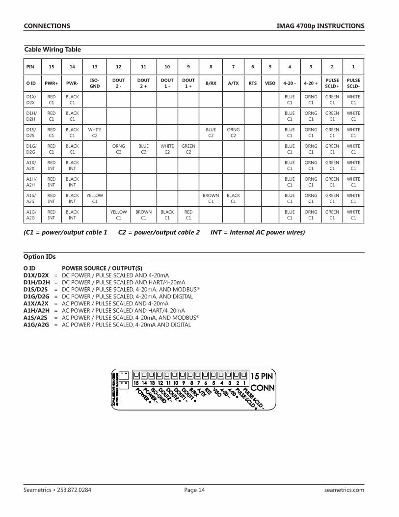
Cable Wiring Table
(C1 = power/output cable 1 C2 = power/output cable 2 INT = Internal AC power wires)
Option IDs
O ID POWER SOURCE / OUTPUT(S)D1X/D2X = DC POWER / PULSE SCALED AND 4-20mAD1H/D2H = DC POWER / PULSE SCALED AND HART/4-20mAD1S/D2S = DC POWER / PULSE SCALED, 4-20mA, AND MODBUS®
D1G/D2G = DC POWER / PULSE SCALED, 4-20mA, AND DIGITALA1X/A2X = AC POWER / PULSE SCALED AND 4-20mAA1H/A2H = AC POWER / PULSE SCALED AND HART/4-20mAA1S/A2S = AC POWER / PULSE SCALED, 4-20mA, AND MODBUS®
A1G/A2G = AC POWER / PULSE SCALED, 4-20mA AND DIGITAL
CONNECTIONS

IMAG 4700p INSTRUCTIONS
Seametrics • 253.872.0284 Page 15 seametrics.com
Pulse or Digital Output Application - Sourcing Mode (Recommended for Rin < 30kΩ)
Pulse or Digital Output Application - Sinking Mode (Recommended for Rin > 30kΩ)
Analog (4-20mA Current Loop) Output Application
** Minimum resistor value is (100 x Vs) ohms. Higher resistances maybe used depending on frequency and cable length. Longer cables and high frequencies require lower resistance.*** Resistor RL converts 4-20mA current to voltage for voltage input only devices.
CONFIGURATION
IMAG 4700p INSTRUCTIONS
Seametrics • 253.872.0284 Page 16 seametrics.com
CONFIGURATION
Cable Shield. In general, the cable shield and its bare drain wire should be left unconnected at the user equipment end of the cable to minimize “ground loop” problems.
Pulse Output Configuration. A pulse output is standard on all models except AC models with Modbus®. Since this is an isolated output, the external equipment must include a DC power source to regenerate the pulse from the open-collector output (transistor equivalent of a contact closure). A pull-up or pull-down resistor may be needed if not included in the user equipment as shown in the diagrams. Both the power source and resistor may be supplied internally in some types of control and monitoring devices. If not, as for most PLC discrete input modules, they must be added externally at the module input terminals. The pulse output rate in volume units/pulse can be set by the user via the SET P tab on the meter’s setup menus.
Analog Output (4-20mA) Configuration. Since the meter’s analog output is isolated and passive, loop power must be supplied externally as shown on previous page. (In addition, an external resistor RL will be needed to convert the loop current to voltage for voltage-only input devices.) The meter’s loop transmitter minimum voltage drop is 6Vdc (8Vdc with HART) which, with wiring resistance and loop power supply voltage, will determine the maximum resistance for RL. The flow rates corresponding to 4 and 20mA can be set by the user via the SET 4 and SET20 tabs on the meter’s setup menus.
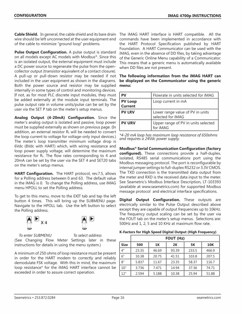
HART Configuration. The HART protocol, rev.7.5, allows for a Polling address between 0 and 63. The default value in the iMAG is 0. To change the Polling address, use iMAG menu HPOLL to set the Polling address.
To get to this menu, move to the EXIT tab and tap the left button 4 times. This will bring up the SUBMENU page. Navigate to the HPOLL tab. Use the left button to select the Polling address.
To enter SUBMENU To select address (See Changing Flow Meter Settings later in these instructions for details in using the menu system.)
A minimum of 250 ohms of loop resistance must be present in order for the HART modem to correctly and reliably demodulate FSK voltage. With this in mind, the maximum loop resistance* for the iMAG HART interface cannot be exceeded in order to assure correct operation.
TAP
X 4TAP
The iMAG HART interface is HART compatible. All the commands have been implemented in accordance with the HART Protocol Specification published by HART Foundation. A HART Communicator can be used with the iMAG, even in the absence of DD files, by taking advantage of the Generic Online Menu capability of a Communicator. This means that a generic menu is automatically available when DD files are not present.
The following information from the iMAG HART can be displayed on the Communicator using the generic menu:
PV Flowrate in units selected for iMAGPV Loop Current
Loop current in mA
PV LRV Lower range value of PV in units selected for iMAG
PV URV Upper range of PV in units selected for iMAG
*4-20 mA loop has maximum loop resistance of 650ohms and requires a 24Vdc power supply.
Modbus® Serial Communication Configuration (factory configured). These connections provide a half-duplex, isolated, RS485 serial communications port using the Modbus messaging protocol. The port is reconfigurable by internal jumper settings to full-duplex RS232 or 3.3V CMOS. The TXD connection is the transmitted data output from the meter and RXD is the received data input to the meter. See Seametric’s Modbus Interface Description, LT-103393 (available at www.seametrics.com) for supported Modbus message protocol and electrical interface specifications.
Digital Output Configuration. These outputs are electrically similar to the Pulse Output described above except they are capable of output frequencies up to 10kHz. The frequency output scaling can be set by the user via the FOUT tab on the meter’s setup menus. Selections are: 500Hz and 1, 2, 5 and 10 KHz at maximum flow rate.
K-Factors for High Speed Digital Output (High Frequency)
FOUT (Hz)Size 500 1K 2K 5K 10K4” 23.35 46.69 93.39 233.5 466.96” 10.38 20.75 41.51 103.8 207.58” 5.837 11.67 23.35 58.37 116.710” 3.736 7.471 14.94 37.36 74.7112” 2.594 5.188 10.38 25.94 51.88

IMAG 4700p INSTRUCTIONS
Seametrics • 253.872.0284 Page 17 seametrics.com
OPERATION
Changing Flow Meter Settings
Home Screen and General Navigation
The HOME Screen displays TOTAL FORWARD flow volume, direction of the flow total and flow RATE along with status conditions such as Empty Pipe. Two buttons below the LCD display are used to access menu screens for viewing and changing meter setup parameters.
These two buttons are light sensors which can detect when a finger is covering them. Only three button touch actions are needed to control navigation through the menus, settings changes and back to the home screen.
1.2345678 100
TOTALCU FTX1000RATEGPM
T UNIT R UNIT SET P DAMP
SET 4 SET 20 SET F EXIT
TOTAL = GALLONSPRESS + TO SET TOTALUNITS FOR DISPLAY
T UNIT R UNIT SET P DAMP
SET 4 SET 20 SET F EXIT
TOTAL:
PRESS TO CHANGE
G A L L O N S
F W D T O TA L
Making Selections
Select the parameter. In the screen for the highlighted tab you will see the current parameter value for that tab. Tapping the right button, move to the tab for the parameter you want to change.
In this example, the first line indicates that the current unit for the TOTAL is GALLONS. The next two lines tell you what to do next.
If you would like to change the TOTAL units, just perform the hold and tap sequence to bring up a screen to change the setting.
Select a new setting. Select the new setting by scrolling through a list of selections as in the screen illustration below by tapping the left button to find a different TOTAL unit.
Accept changes. To accept any changes you have made, perform the hold and tap sequence.
When finished making changes. When you are finished making changes, move to the EXIT tab using the right button.
To return to the HOME screen, perform the hold and tap sequence.
TAP1.2345678 100
TOTALCU FTX1000RATEGPM
T UNIT R UNIT SET P DAMP
SET 4 SET 20 SET F EXIT
TOTAL = GALLONSPRESS + TO SET TOTALUNITS FOR DISPLAY
T UNIT R UNIT SET P DAMP
SET 4 SET 20 SET F EXIT
TOTAL:
PRESS TO CHANGE
G A L L O N S
F W D T O TA L
+HOLD TAP
1.2345678 100
TOTALCU FTX1000RATEGPM
T UNIT R UNIT SET P DAMP
SET 4 SET 20 SET F EXIT
TOTAL = GALLONSPRESS + TO SET TOTALUNITS FOR DISPLAY
T UNIT R UNIT SET P DAMP
SET 4 SET 20 SET F EXIT
TOTAL:
PRESS TO CHANGE
G A L L O N S
F W D T O TA L
TAP
+HOLD TAP
TAP
+HOLD TAP
HORIZONTAL SCROLLING:Tap right button to scroll horizontally through menu tabs or move horizontally within a tab dialog when applicable.
SELECT: Tap left button to change a highlighted item within a tab dialog.
ENTER/EXIT: Hold left button while tapping right button once to enter or exit a tab dialog or to navigate between the HOME and other menu screens.
To enter the Menu System perform the hold and tap sequence. All menu screens consist of two rows of tabs surrounding a dialog box that lets you view and change setup parameters.
Once in the Menu System, move from tab to tab by tapping the right button. (See the next page for details on the various available tabs.)
TAP
TAP
+HOLD TAP
+HOLD TAP
1.2345678 100
TOTALCU FTX1000RATEGPM
T UNIT R UNIT SET P DAMP
SET 4 SET 20 SET F EXIT
TOTAL = GALLONSPRESS + TO SET TOTALUNITS FOR DISPLAY
T UNIT R UNIT SET P DAMP
SET 4 SET 20 SET F EXIT
TOTAL:
PRESS TO CHANGE
G A L L O N S
F W D T O TA L
TAP

IMAG 4700p INSTRUCTIONS
Seametrics • 253.872.0284 Page 18 seametrics.com
OPERATION
Standard Menu Options
Special SUBMENU for further options
The EXIT tab in the MAIN MENU has a second function. If, instead of using the hold and tap sequence to return to the HOME screen, you tap four times, you will be redirected to a SUBMENU screen from which you can access several more options.
Navigation in this SUBMENU is the same as for the MAIN MENU. Whenever you wish, go to the EXIT tab in the SUBMENU and perform the hold and tap sequence to return to the MAIN MENU.
Sub-Menu
INFO COMM MBID FL DIR
SAMP HPOLL FOUT EXIT
PRESS + TO VIEW INFO ABOUT METER
INFO: Meter model number, serial number, and firmware version.
COMM: Modbus® baud rate and parity.
MBID: Modbus® address
FL DIR: Bidirectional flow display options: FWD, REV, or NET.
HPOLL: HART Address
EXIT: Return to MAIN MENU.
Note: Available options will depend on specific meter configuration. Not all options are available on all meters. Options not ordered with your meter will not appear on the meter menu.
T UNITView or change TOTAL volume units
R UNITView or change flow RATE units
SET PView or change pulse output scaling
DAMPView or change filter settings
SET 4View or change flow rate corresponding to 4mA.
SET 20View or change flow rate corresponding to 20mA.
SET FView or change high frequency output scaling.
EXITReturn to HOME SCREEN or enter SUBMENU
T UNIT R UNIT SET P DAMP
SET 4 SET 20 SET F EXIT
TOTAL = GALLONSPRESS + TO SET TOTALUNITS FOR DISPLAY
T UNIT R UNIT SET P DAMP
SET 4 SET 20 SET F EXIT
FLOW RATE = GALLONS/MINPRESS + TO SET RATEUNITS FOR DISPLAY
T UNIT R UNIT SET P DAMP
SET 4 SET 20 SET F EXIT
00001.0 GALLONSPRESS + TO SET GALLONS TOTALIZED PER PULSE SENT OUT PULSE1
T UNIT R UNIT SET P DAMP
SET 4 SET 20 SET F EXIT
DAMPING = 1PRESS + TO SET DAMPING VALUE
T UNIT R UNIT SET P DAMP
SET 4 SET 20 SET F EXIT
00040.0 GALLONS/MINPRESS + TO SET FLOW RATE AT WHICH 4mA(MIN) OUTPUT IS DESIRED
T UNIT R UNIT SET P DAMP
SET 4 SET 20 SET F EXIT
00200.0 GALLONS/MINPRESS + TO SET FLOW RATE AT WHICH 20mA(MAX) OUTPUT IS DESIRED
T UNIT R UNIT SET P DAMP
SET 4 SET 20 SET F EXIT
FMAX = 1 KHzPRESS + TO SET MAX FOUT
T UNIT R UNIT SET P DAMP
SET 4 SET 20 SET F EXIT
PRESS + EXIT MENU AND RETURN TO FLOWDISPLAY

IMAG 4700p INSTRUCTIONS
Seametrics • 253.872.0284 Page 19 seametrics.com
Seametrics • 19026 72nd Avenue South • Kent, Washington 98032 • USA (P) 253.872.0284 • (F) 253.872.0285 • 1.800.975.8153 • seametrics.com
LT-14273r1.0-201604014/1/16
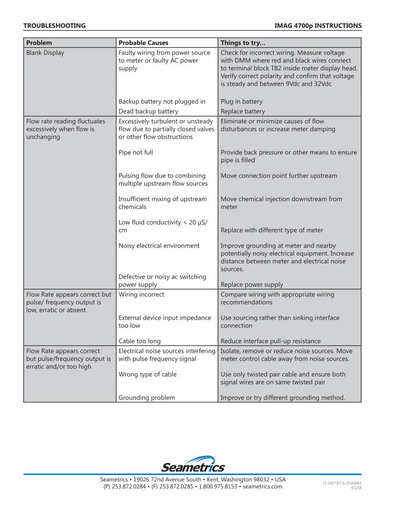
IMAG 4700p INSTRUCTIONSTROUBLESHOOTING
Problem Probable Causes Things to try…Blank Display Faulty wiring from power source
to meter or faulty AC power supply
Check for incorrect wiring. Measure voltage with DMM where red and black wires connect to terminal block TB2 inside meter display head. Verify correct polarity and confirm that voltage is steady and between 9Vdc and 32Vdc
Backup battery not plugged in Plug in batteryDead backup battery Replace battery
Flow rate reading fluctuates excessively when flow is unchanging
Excessively turbulent or unsteady flow due to partially closed valves or other flow obstructions
Pipe not full
Pulsing flow due to combining multiple upstream flow sources
Insufficient mixing of upstream chemicals
Low fluid conductivity < 20 µS/cm
Noisy electrical environment
Defective or noisy ac switching power supply
Eliminate or minimize causes of flow disturbances or increase meter damping
Provide back pressure or other means to ensure pipe is filled
Move connection point further upstream
Move chemical injection downstream from meter
Replace with different type of meter
Improve grounding at meter and nearby potentially noisy electrical equipment. Increase distance between meter and electrical noise sources.
Replace power supplyFlow Rate appears correct but pulse/ frequency output is low, erratic or absent
Wiring incorrect
External device input impedance too low
Cable too long
Compare wiring with appropriate wiring recommendations
Use sourcing rather than sinking interface connection
Reduce interface pull-up resistanceFlow Rate appears correct but pulse/frequency output is erratic and/or too high
Electrical noise sources interfering with pulse frequency signal
Wrong type of cable
Grounding problem
Isolate, remove or reduce noise sources. Move meter control cable away from noise sources.
Use only twisted pair cable and ensure both signal wires are on same twisted pair
Improve or try different grounding method.