Embed Size (px)
Citation preview

RANGER 225 GXT
OPERATOR’S MANUAL
For Machines with Code Number 11522
IM969December, 2008
Safety Depends on YouLincoln arc welding and cuttingequipment is designed and builtwith safety in mind. However, youroverall safety can be increased byproper installation ... and thought-ful operation on your part. DONOT INSTALL, OPERATE ORREPAIR THIS EQUIPMENTWITHOUT READING THISMANUAL AND THE SAFETYPRECAUTIONS CONTAINEDTHROUGHOUT. And, mostimportantly, think before you actand be careful.
• Sales and Service through Subsidiaries and Distributors Worldwide •
Cleveland, Ohio 44117-1199 U.S.A. TEL: 216.481.8100 FAX: 216.486.1751 WEB SITE: www.lincolnelectric.com
• World's Leader in Welding and Cutting Products •
Copyright © Lincoln Global Inc.
®
This manual covers equipment which is no longer in production by The Lincoln Electric Co. Speci�cations and availability of optional features may have changed.
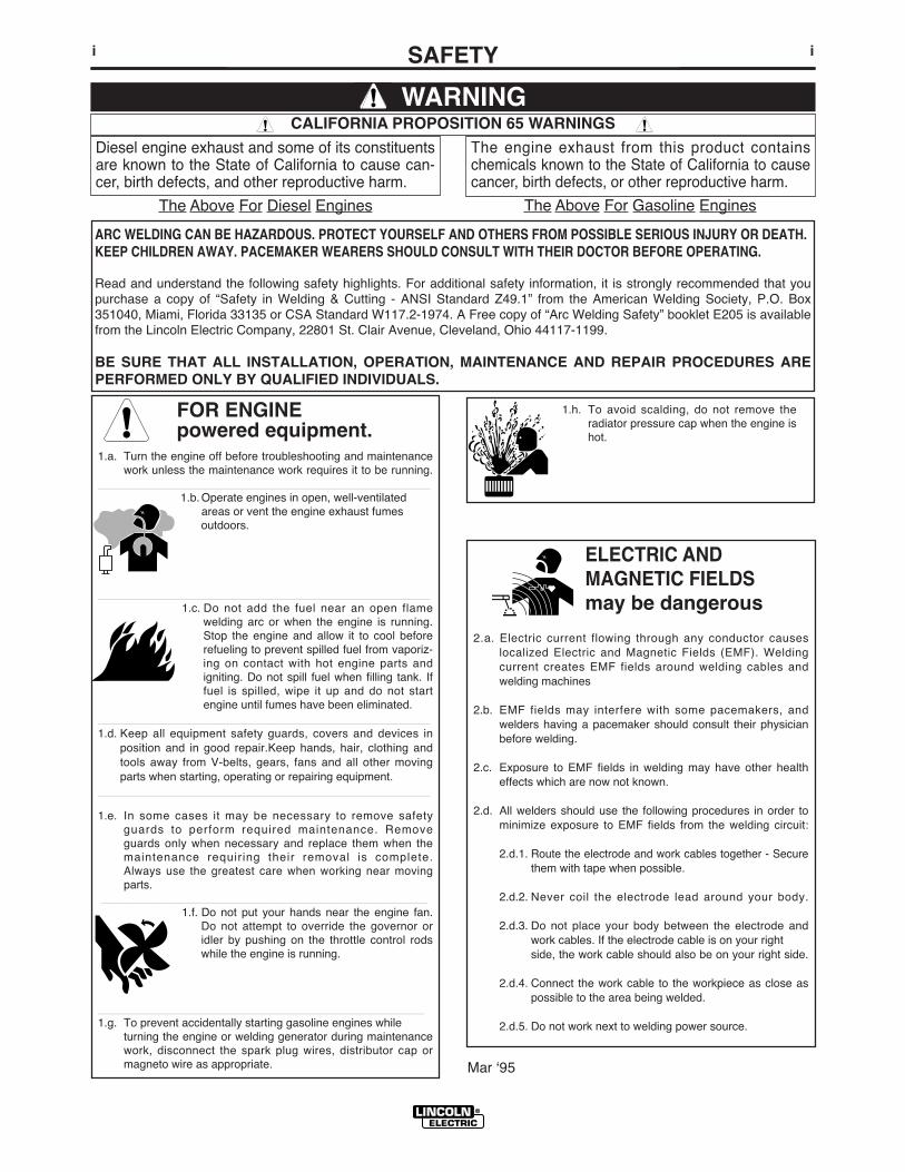
FOR ENGINEpowered equipment.
1.a. Turn the engine off before troubleshooting and maintenancework unless the maintenance work requires it to be running.
____________________________________________________1.b. Operate engines in open, well-ventilated
areas or vent the engine exhaust fumesoutdoors.
____________________________________________________1.c. Do not add the fuel near an open flame
welding arc or when the engine is running.Stop the engine and allow it to cool beforerefueling to prevent spilled fuel from vaporiz-ing on contact with hot engine parts andigniting. Do not spill fuel when filling tank. Iffuel is spilled, wipe it up and do not startengine until fumes have been eliminated.
____________________________________________________1.d. Keep all equipment safety guards, covers and devices in
position and in good repair.Keep hands, hair, clothing andtools away from V-belts, gears, fans and all other movingparts when starting, operating or repairing equipment.
____________________________________________________
1.e. In some cases it may be necessary to remove safetyguards to perform required maintenance. Removeguards only when necessary and replace them when themaintenance requiring their removal is complete.Always use the greatest care when working near movingparts.
___________________________________________________1.f. Do not put your hands near the engine fan.
Do not attempt to override the governor oridler by pushing on the throttle control rodswhile the engine is running.
___________________________________________________1.g. To prevent accidentally starting gasoline engines while
turning the engine or welding generator during maintenancework, disconnect the spark plug wires, distributor cap ormagneto wire as appropriate.
iSAFETYi
ARC WELDING CAN BE HAZARDOUS. PROTECT YOURSELF AND OTHERS FROM POSSIBLE SERIOUS INJURY OR DEATH.KEEP CHILDREN AWAY. PACEMAKER WEARERS SHOULD CONSULT WITH THEIR DOCTOR BEFORE OPERATING.
Read and understand the following safety highlights. For additional safety information, it is strongly recommended that youpurchase a copy of “Safety in Welding & Cutting - ANSI Standard Z49.1” from the American Welding Society, P.O. Box351040, Miami, Florida 33135 or CSA Standard W117.2-1974. A Free copy of “Arc Welding Safety” booklet E205 is availablefrom the Lincoln Electric Company, 22801 St. Clair Avenue, Cleveland, Ohio 44117-1199.
BE SURE THAT ALL INSTALLATION, OPERATION, MAINTENANCE AND REPAIR PROCEDURES AREPERFORMED ONLY BY QUALIFIED INDIVIDUALS.
WARNING
Mar ʻ95
ELECTRIC ANDMAGNETIC FIELDSmay be dangerous
2.a. Electric current flowing through any conductor causeslocalized Electric and Magnetic Fields (EMF). Weldingcurrent creates EMF fields around welding cables andwelding machines
2.b. EMF fields may interfere with some pacemakers, andwelders having a pacemaker should consult their physicianbefore welding.
2.c. Exposure to EMF fields in welding may have other healtheffects which are now not known.
2.d. All welders should use the following procedures in order tominimize exposure to EMF fields from the welding circuit:
2.d.1. Route the electrode and work cables together - Securethem with tape when possible.
2.d.2. Never coil the electrode lead around your body.
2.d.3. Do not place your body between the electrode andwork cables. If the electrode cable is on your rightside, the work cable should also be on your right side.
2.d.4. Connect the work cable to the workpiece as close aspossible to the area being welded.
2.d.5. Do not work next to welding power source.
1.h. To avoid scalding, do not remove theradiator pressure cap when the engine ishot.
CALIFORNIA PROPOSITION 65 WARNINGS
Diesel engine exhaust and some of its constituentsare known to the State of California to cause can-cer, birth defects, and other reproductive harm.
The engine exhaust from this product containschemicals known to the State of California to causecancer, birth defects, or other reproductive harm.
The Above For Diesel Engines The Above For Gasoline Engines
iiSAFETYii
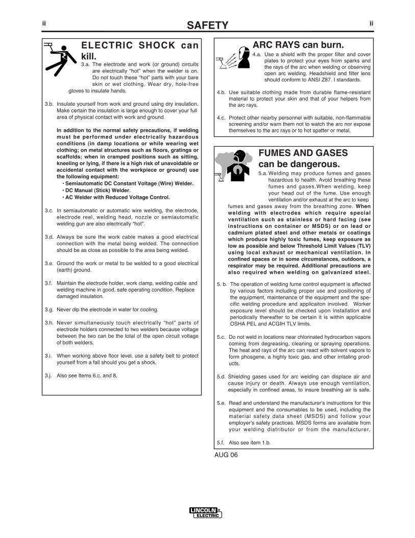
ARC RAYS can burn.4.a. Use a shield with the proper filter and cover
plates to protect your eyes from sparks andthe rays of the arc when welding or observingopen arc welding. Headshield and filter lensshould conform to ANSI Z87. I standards.
4.b. Use suitable clothing made from durable flame-resistantmaterial to protect your skin and that of your helpers fromthe arc rays.
4.c. Protect other nearby personnel with suitable, non-flammablescreening and/or warn them not to watch the arc nor exposethemselves to the arc rays or to hot spatter or metal.
ELECTRIC SHOCK cankill.3.a. The electrode and work (or ground) circuits
are electrically “hot” when the welder is on.Do not touch these “hot” parts with your bareskin or wet clothing. Wear dry, hole-free
gloves to insulate hands.
3.b. Insulate yourself from work and ground using dry insulation.Make certain the insulation is large enough to cover your fullarea of physical contact with work and ground.
In addition to the normal safety precautions, if weldingmust be performed under electrically hazardousconditions (in damp locations or while wearing wetclothing; on metal structures such as floors, gratings orscaffolds; when in cramped positions such as sitting,kneeling or lying, if there is a high risk of unavoidable oraccidental contact with the workpiece or ground) usethe following equipment:
• Semiautomatic DC Constant Voltage (Wire) Welder.• DC Manual (Stick) Welder.• AC Welder with Reduced Voltage Control.
3.c. In semiautomatic or automatic wire welding, the electrode,electrode reel, welding head, nozzle or semiautomaticwelding gun are also electrically “hot”.
3.d. Always be sure the work cable makes a good electricalconnection with the metal being welded. The connectionshould be as close as possible to the area being welded.
3.e. Ground the work or metal to be welded to a good electrical(earth) ground.
3.f. Maintain the electrode holder, work clamp, welding cable andwelding machine in good, safe operating condition. Replacedamaged insulation.
3.g. Never dip the electrode in water for cooling.
3.h. Never simultaneously touch electrically “hot” parts ofelectrode holders connected to two welders because voltagebetween the two can be the total of the open circuit voltageof both welders.
3.i. When working above floor level, use a safety belt to protectyourself from a fall should you get a shock.
3.j. Also see Items 6.c. and 8.
FUMES AND GASEScan be dangerous.5.a. Welding may produce fumes and gases
hazardous to health. Avoid breathing thesefumes and gases.When welding, keepyour head out of the fume. Use enoughventilation and/or exhaust at the arc to keep
fumes and gases away from the breathing zone. Whenwelding with electrodes which require specialventilation such as stainless or hard facing (seeinstructions on container or MSDS) or on lead orcadmium plated steel and other metals or coatingswhich produce highly toxic fumes, keep exposure aslow as possible and below Threshold Limit Values (TLV)using local exhaust or mechanical ventilation. Inconfined spaces or in some circumstances, outdoors, arespirator may be required. Additional precautions arealso required when welding on galvanized steel.
5. b. The operation of welding fume control equipment is affectedby various factors including proper use and positioning ofthe equipment, maintenance of the equipment and the spe-cific welding procedure and applicaiton involved. Workerexposure level should be checked upon installation andperiodically thereafter to be certain it is within applicableOSHA PEL and ACGIH TLV limits.
5.c. Do not weld in locations near chlorinated hydrocarbon vaporscoming from degreasing, cleaning or spraying operations.The heat and rays of the arc can react with solvent vapors toform phosgene, a highly toxic gas, and other irritating prod-ucts.
5.d. Shielding gases used for arc welding can displace air andcause injury or death. Always use enough ventilation,especially in confined areas, to insure breathing air is safe.
5.e. Read and understand the manufacturerʼs instructions for thisequipment and the consumables to be used, including thematerial safety data sheet (MSDS) and follow youremployerʼs safety practices. MSDS forms are available fromyour welding distributor or from the manufacturer.
5.f. Also see item 1.b.
AUG 06
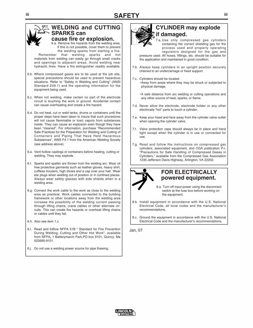
FOR ELECTRICALLYpowered equipment.
8.a. Turn off input power using the disconnectswitch at the fuse box before working onthe equipment.
8.b. Install equipment in accordance with the U.S. NationalElectrical Code, all local codes and the manufacturerʼsrecommendations.
8.c. Ground the equipment in accordance with the U.S. NationalElectrical Code and the manufacturerʼs recommendations.
CYLINDER may explodeif damaged.7.a. Use only compressed gas cylinders
containing the correct shielding gas for theprocess used and properly operatingregulators designed for the gas and
pressure used. All hoses, fittings, etc. should be suitable forthe application and maintained in good condition.
7.b. Always keep cylinders in an upright position securelychained to an undercarriage or fixed support.
7.c. Cylinders should be located:• Away from areas where they may be struck or subjected tophysical damage.
• A safe distance from arc welding or cutting operations andany other source of heat, sparks, or flame.
7.d. Never allow the electrode, electrode holder or any otherelectrically “hot” parts to touch a cylinder.
7.e. Keep your head and face away from the cylinder valve outletwhen opening the cylinder valve.
7.f. Valve protection caps should always be in place and handtight except when the cylinder is in use or connected foruse.
7.g. Read and follow the instructions on compressed gascylinders, associated equipment, and CGA publication P-l,“Precautions for Safe Handling of Compressed Gases inCylinders,” available from the Compressed Gas Association1235 Jefferson Davis Highway, Arlington, VA 22202.
iiiSAFETYiii
Jan, 07
WELDING and CUTTINGSPARKS cancause fire or explosion.6.a. Remove fire hazards from the welding area.
If this is not possible, cover them to preventthe welding sparks from starting a fire.
Remember that welding sparks and hotmaterials from welding can easily go through small cracksand openings to adjacent areas. Avoid welding nearhydraulic lines. Have a fire extinguisher readily available.
6.b. Where compressed gases are to be used at the job site,special precautions should be used to prevent hazardoussituations. Refer to “Safety in Welding and Cutting” (ANSIStandard Z49.1) and the operating information for theequipment being used.
6.c. When not welding, make certain no part of the electrodecircuit is touching the work or ground. Accidental contactcan cause overheating and create a fire hazard.
6.d. Do not heat, cut or weld tanks, drums or containers until theproper steps have been taken to insure that such procedureswill not cause flammable or toxic vapors from substancesinside. They can cause an explosion even though they havebeen “cleaned”. For information, purchase “RecommendedSafe Practices for the Preparation for Welding and Cutting ofContainers and Piping That Have Held HazardousSubstances”, AWS F4.1 from the American Welding Society(see address above).
6.e. Vent hollow castings or containers before heating, cutting orwelding. They may explode.
6.f. Sparks and spatter are thrown from the welding arc. Wear oilfree protective garments such as leather gloves, heavy shirt,cuffless trousers, high shoes and a cap over your hair. Wearear plugs when welding out of position or in confined places.Always wear safety glasses with side shields when in awelding area.
6.g. Connect the work cable to the work as close to the weldingarea as practical. Work cables connected to the buildingframework or other locations away from the welding areaincrease the possibility of the welding current passingthrough lifting chains, crane cables or other alternate cir-cuits. This can create fire hazards or overheat lifting chainsor cables until they fail.
6.h. Also see item 1.c.
6.I. Read and folllow NFPA 51B “ Standard for Fire PreventionDuring Welding, Cutting and Other Hot Work”, availablefrom NFPA, 1 Batterymarch Park,PO box 9101, Quincy, Ma022690-9101.
6.j. Do not use a welding power source for pipe thawing.

Mar. ʻ93
ivSAFETYiv
PRÉCAUTIONS DE SÛRETÉPour votre propre protection lire et observer toutes les instructionset les précautions de sûreté specifiques qui parraissent dans cemanuel aussi bien que les précautions de sûreté générales suiv-antes:
Sûreté Pour Soudage A LʼArc1. Protegez-vous contre la secousse électrique:
a. Les circuits à lʼélectrode et à la piéce sont sous tensionquand la machine à souder est en marche. Eviter toujourstout contact entre les parties sous tension et la peau nueou les vétements mouillés. Porter des gants secs et sanstrous pour isoler les mains.
b. Faire trés attention de bien sʼisoler de la masse quand onsoude dans des endroits humides, ou sur un planchermetallique ou des grilles metalliques, principalement dansles positions assis ou couché pour lesquelles une grandepartie du corps peut être en contact avec la masse.
c. Maintenir le porte-électrode, la pince de masse, le câblede soudage et la machine à souder en bon et sûr étatdefonctionnement.
d.Ne jamais plonger le porte-électrode dans lʼeau pour lerefroidir.
e. Ne jamais toucher simultanément les parties sous tensiondes porte-électrodes connectés à deux machines à souderparce que la tension entre les deux pinces peut être letotal de la tension à vide des deux machines.
f. Si on utilise la machine à souder comme une source decourant pour soudage semi-automatique, ces precautionspour le porte-électrode sʼapplicuent aussi au pistolet desoudage.
2. Dans le cas de travail au dessus du niveau du sol, se protégercontre les chutes dans le cas ou on recoit un choc. Ne jamaisenrouler le câble-électrode autour de nʼimporte quelle partiedu corps.
3. Un coup dʼarc peut être plus sévère quʼun coup de soliel,donc:
a. Utiliser un bon masque avec un verre filtrant appropriéainsi quʼun verre blanc afin de se protéger les yeux du ray-onnement de lʼarc et des projections quand on soude ouquand on regarde lʼarc.
b. Porter des vêtements convenables afin de protéger lapeau de soudeur et des aides contre le rayonnement delʻarc.
c. Protéger lʼautre personnel travaillant à proximité ausoudage à lʼaide dʼécrans appropriés et non-inflammables.
4. Des gouttes de laitier en fusion sont émises de lʼarc desoudage. Se protéger avec des vêtements de protection libresde lʼhuile, tels que les gants en cuir, chemise épaisse, pan-talons sans revers, et chaussures montantes.
5. Toujours porter des lunettes de sécurité dans la zone desoudage. Utiliser des lunettes avec écrans lateraux dans leszones où lʼon pique le laitier.
6. Eloigner les matériaux inflammables ou les recouvrir afin deprévenir tout risque dʼincendie dû aux étincelles.
7. Quand on ne soude pas, poser la pince à une endroit isolé dela masse. Un court-circuit accidental peut provoquer unéchauffement et un risque dʼincendie.
8. Sʼassurer que la masse est connectée le plus prés possiblede la zone de travail quʼil est pratique de le faire. Si on placela masse sur la charpente de la construction ou dʼautresendroits éloignés de la zone de travail, on augmente le risquede voir passer le courant de soudage par les chaines de lev-age, câbles de grue, ou autres circuits. Cela peut provoquerdes risques dʼincendie ou dʼechauffement des chaines et descâbles jusquʼà ce quʼils se rompent.
9. Assurer une ventilation suffisante dans la zone de soudage.Ceci est particuliérement important pour le soudage de tôlesgalvanisées plombées, ou cadmiées ou tout autre métal quiproduit des fumeés toxiques.
10. Ne pas souder en présence de vapeurs de chlore provenantdʼopérations de dégraissage, nettoyage ou pistolage. Lachaleur ou les rayons de lʼarc peuvent réagir avec les vapeursdu solvant pour produire du phosgéne (gas fortement toxique)ou autres produits irritants.
11. Pour obtenir de plus amples renseignements sur la sûreté,voir le code “Code for safety in welding and cutting” CSAStandard W 117.2-1974.
PRÉCAUTIONS DE SÛRETÉ POURLES MACHINES À SOUDER ÀTRANSFORMATEUR ET ÀREDRESSEUR
1. Relier à la terre le chassis du poste conformement au code delʼélectricité et aux recommendations du fabricant. Le dispositifde montage ou la piece à souder doit être branché à unebonne mise à la terre.
2. Autant que possible, Iʼinstallation et lʼentretien du poste seronteffectués par un électricien qualifié.
3. Avant de faires des travaux à lʼinterieur de poste, la debranch-er à lʼinterrupteur à la boite de fusibles.
4. Garder tous les couvercles et dispositifs de sûreté à leurplace.

vv
Thank You for selecting a QUALITY product by Lincoln Electric. We want youto take pride in operating this Lincoln Electric Company product••• as much pride as we have in bringing this product to you!
Read this Operators Manual completely before attempting to use this equipment. Save this manual and keep ithandy for quick reference. Pay particular attention to the safety instructions we have provided for your protection.The level of seriousness to be applied to each is explained below:
WARNINGThis statement appears where the information must be followed exactly to avoid serious personal injury or loss of life.
This statement appears where the information must be followed to avoid minor personal injury or damage to this equipment.
CAUTION
Please Examine Carton and Equipment For Damage ImmediatelyWhen this equipment is shipped, title passes to the purchaser upon receipt by the carrier. Consequently, Claimsfor material damaged in shipment must be made by the purchaser against the transportation company at thetime the shipment is received.
Please record your equipment identification information below for future reference. This information can befound on your machine nameplate.
Product _________________________________________________________________________________
Model Number ___________________________________________________________________________
Code Number or Date Code_________________________________________________________________
Serial Number____________________________________________________________________________
Date Purchased___________________________________________________________________________
Where Purchased_________________________________________________________________________
Whenever you request replacement parts or information on this equipment, always supply the information youhave recorded above. The code number is especially important when identifying the correct replacement parts.
On-Line Product Registration
- Register your machine with Lincoln Electric either via fax or over the Internet.
• For faxing: Complete the form on the back of the warranty statement included in the literature packetaccompanying this machine and fax the form per the instructions printed on it.
• For On-Line Registration: Go to our WEB SITE at www.lincolnelectric.com. Choose “Quick Links” and then“Product Registration”. Please complete the form and submit your registration.
CUSTOMER ASSISTANCE POLICYThe business of The Lincoln Electric Company is manufacturing and selling high quality welding equipment, consumables, and cutting equip-ment. Our challenge is to meet the needs of our customers and to exceed their expectations. On occasion, purchasers may ask LincolnElectric for advice or information about their use of our products. We respond to our customers based on the best information in our posses-sion at that time. Lincoln Electric is not in a position to warrant or guarantee such advice, and assumes no liability, with respect to such infor-mation or advice. We expressly disclaim any warranty of any kind, including any warranty of fitness for any customerʼs particular purpose,with respect to such information or advice. As a matter of practical consideration, we also cannot assume any responsibility for updating orcorrecting any such information or advice once it has been given, nor does the provision of information or advice create, expand or alter anywarranty with respect to the sale of our products.
Lincoln Electric is a responsive manufacturer, but the selection and use of specific products sold by Lincoln Electric is solely within the controlof, and remains the sole responsibility of the customer. Many variables beyond the control of Lincoln Electric affect the results obtained inapplying these types of fabrication methods and service requirements.
Subject to Change – This information is accurate to the best of our knowledge at the time of printing. Please refer to www.lincolnelectric.comfor any updated information.

vi vi TABLE OF CONTENTSPage
Installation.......................................................................................................................Section ATechnical Specifications.......................................................................................................A-1
Safety Precautions ........................................................................................................A-2Machine Grounding.......................................................................................................A-2Spark Arrester ...............................................................................................................A-2Towing...........................................................................................................................A-2Vehicle Mounting...........................................................................................................A-3
Pre-Operation Engine Service..............................................................................................A-3Fuel, Oil, Battery Connections ......................................................................................A-3Welding Cable Connections..........................................................................................A-4 Angle of Operation ........................................................................................................A-4Lifting, Additional Safety Precautions............................................................................A-4High Altitude Operation .................................................................................................A-4Muffler Outlet Pipe ........................................................................................................A-4Location and Ventilation................................................................................................A-5Stacking ........................................................................................................................A-5Connection of Wire Feeders .........................................................................................A-5Connection of Tig Module .............................................................................................A-5Additional Safety Precautions .......................................................................................A-5
Welding Operation Output, Auxiliary Power Receptacles, and Plugs .................................A-6Motor Starting and Extension Cord Length Table ................................................................A-6Electrical Device Used with the Ranger 10,000 ...................................................................A-7Auxiliary Power While Welding, Standby Power Connections ............................................A-8Premises Wiring ...................................................................................................................A-9
________________________________________________________________________________Operation.........................................................................................................................Section B
Safety Precautions ...............................................................................................................B-1General Description..............................................................................................................B-1Welder Controls Function and Operation .............................................................................B-1Range, Polarity Control Switch and Fuel Consumption .......................................................B-2
Start in/Shutdown Instructions.....................................................................................................B-3 Starting the Engine........................................................................................................B-3Safety Precautions ........................................................................................................B-3Stopping the Engine......................................................................................................B-3Break-In Period .............................................................................................................B-3
Welding Process ..................................................................................................................B-4Stick (Constant Current) Welding..................................................................................B-4TIG (Constant Current) Welding ..................................................................................B-4Wire Feed Welding Processes (Constant Voltage)......................................................B-4Arc Gouging ..................................................................................................................B-4Summary of Welding Processes ...................................................................................B-5
________________________________________________________________________________Accessories ........................................................................................................Section C
Optional Equipment ...............................................................................................C-1Recommended Equipment ....................................................................................C-2
________________________________________________________________________Maintenance ....................................................................................................Section D
Safety Precautions ................................................................................................D-1Routine Engine Maintenance ..........................................................................D-1,D2Engine Adjustments...............................................................................................D-3Slip Rings ..............................................................................................................D-3
Battery Maintenance .......................................................................................D-3Engine Maintenance Parts..............................................................................D-3
________________________________________________________________________Troubleshooting ..............................................................................................Section E
How to Use Troubleshooting Guide.......................................................................E-1Troubleshooting Guide...................................................................................E-2, E-3
________________________________________________________________________Wiring Diagrams & Dimension Print..............................................................Section F
Wiring and Connection Diagrams....................................................................F-1,F-2Dimension Print .............................................................................................................F3
________________________________________________________________________Parts List.................................................................................................................P-581
________________________________________________________________________
A-1INSTALLATION
RANGER® 225 GXT
A-1
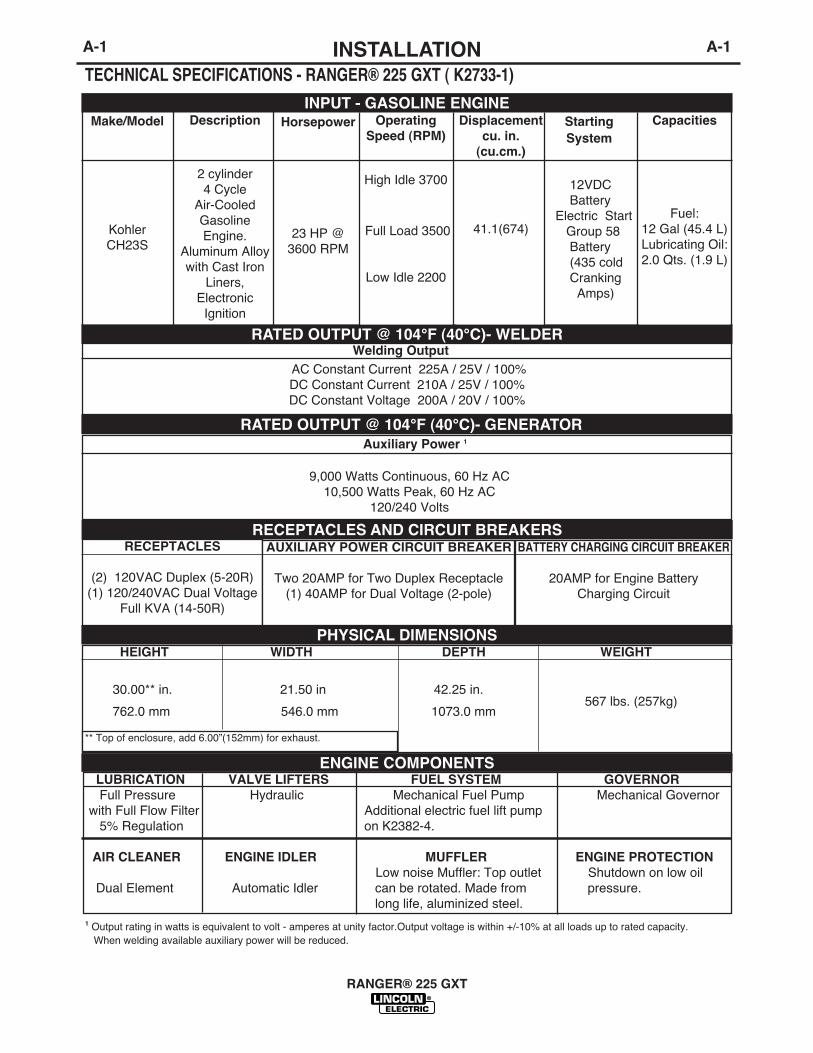
TECHNICAL SPECIFICATIONS - RANGER® 225 GXT ( K2733-1)
INPUT - GASOLINE ENGINE
RATED OUTPUT @ 104°F (40°C)- WELDER
RATED OUTPUT @ 104°F (40°C)- GENERATOR
Welding Output AC Constant Current 225A / 25V / 100%DC Constant Current 210A / 25V / 100%DC Constant Voltage 200A / 20V / 100%
Auxiliary Power 1
9,000 Watts Continuous, 60 Hz AC10,500 Watts Peak, 60 Hz AC
120/240 Volts
Make/Model
KohlerCH23S
Description
2 cylinder4 Cycle
Air-CooledGasolineEngine.
Aluminum Alloywith Cast Iron
Liners,Electronic
Ignition
OperatingSpeed (RPM)
High Idle 3700
Full Load 3500
Low Idle 2200
Displacementcu. in.
(cu.cm.)
41.1(674)
Capacities
Fuel:12 Gal (45.4 L)Lubricating Oil:2.0 Qts. (1.9 L)
Horsepower
23 HP @3600 RPM
StartingSystem
12VDCBattery
Electric StartGroup 58Battery(435 coldCranking
Amps)
1 Output rating in watts is equivalent to volt - amperes at unity factor.Output voltage is within +/-10% at all loads up to rated capacity.When welding available auxiliary power will be reduced.
RECEPTACLES
(2) 120VAC Duplex (5-20R)(1) 120/240VAC Dual Voltage
Full KVA (14-50R)
BATTERY CHARGING CIRCUIT BREAKER
20AMP for Engine BatteryCharging Circuit
AUXILIARY POWER CIRCUIT BREAKER
Two 20AMP for Two Duplex Receptacle(1) 40AMP for Dual Voltage (2-pole)
RECEPTACLES AND CIRCUIT BREAKERS
HEIGHT WIDTH DEPTH WEIGHT
30.00** in. 21.50 in 42.25 in.
762.0 mm 546.0 mm 1073.0 mm
LUBRICATION VALVE LIFTERS FUEL SYSTEM GOVERNORFull Pressure Hydraulic Mechanical Fuel Pump Mechanical Governor
with Full Flow Filter Additional electric fuel lift pump5% Regulation on K2382-4.
AIR CLEANER ENGINE IDLER MUFFLER ENGINE PROTECTIONLow noise Muffler: Top outlet Shutdown on low oil
Dual Element Automatic Idler can be rotated. Made from pressure.long life, aluminized steel.
PHYSICAL DIMENSIONS
ENGINE COMPONENTS
** Top of enclosure, add 6.00”(152mm) for exhaust.
567 lbs. (257kg)

A-2INSTALLATION
RANGER® 225 GXT
A-2
SAFETY PRECAUTIONS
MACHINE GROUNDING
Because this portable engine driven welder or genera-tor creates itʼs own power, it is not necessary to con-nect itʼs frame to an earth ground, unless the machineis connected to premises wiring (your home, shop,etc.).
To prevent dangerous electric shock, other equip-ment to which this engine driven welder suppliespower must:
• be grounded to the frame of the welder using a grounded type plug, or be double insulated.
Do not ground the machine to a pipe that carriesexplosive or combustible material.------------------------------------------------------------------------
When this welder is mounted on a truck or trailer, itʼsframe must be electrically bonded to the metal frameof the vehicle. Use a #8 or larger copper wire connect-ed between the machine grounding stud and theframe of the vehicle.
Where this engine driven welder is connected topremises wiring such as that in your home or shop, itʼsframe must be connected to the system earth ground.See further connection instructions in the section enti-tled “Standby Power Connections”, as well as the arti-cle on grounding in the latest National Electrical Codeand the local code.
In general, if the machine is to be grounded, it shouldbe connected with a #8 or larger copper wire to a solidearth ground such as a metal water pipe going intothe ground for at least ten feet and having no insulat-ed joints, or to the metal framework of a buildingwhich has been effectively grounded. The NationalElectrical Code lists a number of alternate means ofgrounding electrical equipment. A machine groundingstud marked with the symbol is provided on thefront of the welder.
SPARK ARRESTER
Some federal, state, or local laws may require thatgasoline engines be equipped with exhaust sparkarresters when they are operated in certain locationswhere unarrested sparks may present a fire hazard.The standard muffler included with this welder doesnot qualify as a spark arrester. When required by localregulations, the K1898-1 spark arrester must beinstalled and properly maintained.
An incorrect arrester may lead to damage to theengine or adversely affect performance.------------------------------------------------------------------------TOWINGThe recommended trailer for use with this equipmentfor road, in-plant and yard towing by a vehicle(1) isLincolnʼs K2635-1. If the user adapts a non-Lincolntrailer, he must assume responsibility that the methodof attachment and usage does not result in a safetyhazard nor damage the welding equipment. Some ofthe factors to be considered are as follows:
1. Design capacity of trailer vs. weight of Lincolnequipment and likely additional attachments.
2. Proper support of, and attachment to, the base ofthe welding equipment so there will be no unduestress to the framework.
CAUTION
Do not attempt to use this equipment until youhave thoroughly read the engine manufacturerʼsmanual supplied with your welder. It includesimportant safety precautions, detailed enginestarting, operating and maintenance instructions,and parts lists.------------------------------------------------------------------------
ELECTRIC SHOCK can kill.• Do not touch electrically live parts orelectrode with skin or wet clothing.• Insulate yourself from work andground• Always wear dry insulating gloves.
------------------------------------------------------------------------ENGINE EXHAUST can kill.• Use in open, well ventilated areas orvent exhaust outside.
------------------------------------------------------------------------MOVING PARTS can injure.• Do not operate with doors open orguards off.• Stop engine before servicing.• Keep away from moving parts.
------------------------------------------------------------------------
See additional warning information atfront of this operatorʼs manual.
-----------------------------------------------------------
WARNING
WARNING
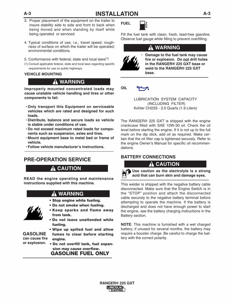
FUEL
Fill the fuel tank with clean, fresh, lead-free gasoline.Observe fuel gauge while filling to prevent overfilling.
OIL
The RANGER® 225 GXT is shipped with the enginecrankcase filled with SAE 10W-30 oil. Check the oillevel before starting the engine. If it is not up to the fullmark on the dip stick, add oil as required. Make cer-tain that the oil filler cap is tightened securely. Refer tothe engine Ownerʼs Manual for specific oil recommen-dations.
BATTERY CONNECTIONS
Use caution as the electrolyte is a strongacid that can burn skin and damage eyes.
-----------------------------------------------------------------------This welder is shipped with the negative battery cabledisconnected. Make sure that the Engine Switch is inthe “STOP” position and attach the disconnectedcable securely to the negative battery terminal beforeattempting to operate the machine. If the battery isdischarged and does not have enough power to startthe engine, see the battery charging instructions in theBattery section.
NOTE: This machine is furnished with a wet chargedbattery; if unused for several months, the battery mayrequire a booster charge. Be careful to charge the bat-tery with the correct polarity.
3. Proper placement of the equipment on the trailer toinsure stability side to side and front to back whenbeing moved and when standing by itself whilebeing operated or serviced.
4. Typical conditions of use, i.e., travel speed; rough-ness of surface on which the trailer will be operated;environmental conditions.
5. Conformance with federal, state and local laws(1)
(1) Consult applicable federal, state and local laws regarding specific
requirements for use on public highways.
A-3INSTALLATION
RANGER® 225 GXT
A-3
PRE-OPERATION SERVICE
READ the engine operating and maintenanceinstructions supplied with this machine.
CAUTION
LUBRICATION SYSTEM CAPACITY(INCLUDING FILTER)
Kohler CH23S - 2.0 Quarts (1.9 Liters)
• Damage to the fuel tank may causefire or explosion. Do not drill holesin the RANGER® 225 GXT base orweld to the RANGER® 225 GXTbase.
-----------------------------------------------------------------------
WARNING
CAUTION
• Stop engine while fueling.• Do not smoke when fueling.• Keep sparks and flame away
from tank.• Do not leave unattended while
fueling.• Wipe up spilled fuel and allow
fumes to clear before startingengine.
• Do not overfill tank, fuel expan-sion may cause overflow.
GASOLINE FUEL ONLY------------------------------------------------------------------------
WARNING
GASOLINEcan cause fireor explosion.
VEHICLE MOUNTING
Improperly mounted concentrated loads maycause unstable vehicle handling and tires or othercomponents to fail.
• Only transport this Equipment on serviceablevehicles which are rated and designed for suchloads.
• Distribute, balance and secure loads so vehicleis stable under conditions of use.
• Do not exceed maximum rated loads for compo-nents such as suspension, axles and tires.
• Mount equipment base to metal bed or frame ofvehicle.
• Follow vehicle manufacturerʼs instructions.------------------------------------------------------------------------
WARNING

A-4INSTALLATION
RANGER® 225 GXT
A-4
WELDING OUTPUT CABLES
With the engine off, connect the electrode and workcables to the studs provided. These connectionsshould be checked periodically and tightened if neces-sary. Loose connections will result in overheating ofthe output studs.
When welding at a considerable distance from thewelder, be sure you use ample size welding cables.Listed below are copper cable sizes recommended forthe rated current and duty cycle. Lengths stipulatedare the distance from the welder to work and back tothe welder again. Cable sizes are increased forgreater lengths primarily for the purpose of minimizingcable voltage drop.
ANGLE OF OPERATION
Internal combustion engines are designed to run in alevel condition which is where the optimum perfor-mance is achieved. The maximum angle of operationfor the engine is 15 degrees from horizontal in anydirection. If the engine is to be operated at an angle,provisions must be made for checking and maintain-ing the oil at the normal (FULL) oil capacity in thecrankcase in a level condition.
When operating at an angle, the effective fuel capacitywill be slightly less than the specified 12 Gal. (45 L).
LIFTING
The RANGER® 225 GXT weighs approximately685lbs.(411kg) with a full tank of gasoline. A lift bail ismounted to the machine and should always be usedwhen lifting the machine.
ADDITIONAL SAFETY PRECAUTION
HIGH ALTITUDE OPERATIONAt higher altitudes, Welder output de-rating may benecessary. For maximum rating, de-rate the welderoutput 3.5% for every 1000 ft. (305m) above 3000 ft.(914m). If operation will consistently be at altitudesabove 5,000 ft. (1525m), a carburetor jet designed forhigh altitudes should be installed. This will result inbetter fuel economy, cleaner exhaust and longerspark plug life. It will not give increased power.Contact your local authorized engine service shop forhigh altitude jet kits that are available from the enginemanufacturer.
Do not operate with a high altitude jet installed ataltitudes below 5000 ft. This will result in theengine running too lean and result in higherengine operating temperatures which can shortenengine life.------------------------------------------------------------------------MUFFLER OUTLET PIPE
Using the clamp provided secure the outlet pipe to theoutlet tube with the pipe positioned such that it willdirect the exhaust in the desired direction. Tightenusing a 9/16” socket or wrench.
CAUTION
• Lift only with equipment ofadequate lifting capacity.
• Be sure machine is stablewhen lifting.
• Do not lift this machine usinglift bail if it is equipped with aheavy accessory such as trail-er or gas cylinder.
FALLING • Do not lift machine if lift bail is
EQUIPMENT can damaged.
cause injury. • Do not operate machine while
suspended from lift bail.
------------------------------------------------------------------------
WARNING
TOTAL COMBINED LENGTH OFELECTRODE AND WORK CABLES
0-100 Ft. (0-31m)
100-150 Ft. (31-46m)
150-200 Ft. (46-61m)
225 Amps100% Duty Cycle
1 AWG
1 AWG
1/0 AWG

A-5INSTALLATION
RANGER® 225 GXT
A-5
LOCATION / VENTILATIONThe welder should be located to provide an unrestrict-ed flow of clean, cool air to the cooling air inlets and toavoid heated air coming out of the welder recirculating back to the cooling air inlet. Also, locate the welder sothat engine exhaust fumes are properly vented to anoutside area.
STACKING
RANGER® 225 GXT machines cannot be stacked.
CONNECTION OF LINCOLN ELECTRICWIRE FEEDERS
Shut off welder before making any electricalconnections.------------------------------------------------------------------------WIRE FEED (CONSTANT VOLTAGE)CONNECTION OF LN-15 ACROSS-THE-ARC WIREFEEDERThe LN-15 has an internal contactor and the electrodeis not energized until the gun trigger is closed. Whenthe gun trigger is closed the wire will begin to feed andthe welding process is started.
• Shut the welder off.• Connect the electrode cable from the LN-15 to
the“ELECTRODE” terminal of the welder. Connectthe work cable to the “TO WORK” terminal of thewelder.
• Set the Polarity switch to the desired polarity, eitherDC (-) or DC (+).
• Attach the single lead from the front of the LN-15to work using the spring clip at the end of the lead.This is a control lead to supply current to the wirefeeder motor; it does not carry welding current.
• Set the “RANGE” switch to the “WIRE FEED-CV”position
• Place the Engine switch in the “Auto Idle” positionwhen welding with MIG wire instead of self-shieldedcore wire, weld starts can be improved by settingthe idle mode to “HIGH”.
• Adjust the wire feed speed at the LN-15 and adjustthe welding voltage with the output “CONTROL” atthe welder. Output “CONTROL” must be set above 3when welding with MIG wire instead of self-shieldedcore wire, weld starts can be improved by settingthe idle mode to “HIGH”.
Note: LN-15 Control Cable model will not work withthe RANGER® 225 GXT.
• Position the “RANGE” switch to the “WIRE FEEDCV” position.
• Attach the single lead from the LN-25 control boxto the work using the spring clip on the end of thelead - it carries no welding current.
• Place the engine switch in the “AUTO IDLE” posi-tion.
• When welding with MIG wire instead of self-shielded core wire, weld starts can be improvedby setting the idle mode to “HIGH”.
• Adjust wire feed speed at the LN-25 and adjustthe welding voltage with the output “CONTROL”at the welder.
NOTE: The welding electrode is energized at alltimes, unless an LN-25 with built-in contactor is used.If the output “CONTROL” is set below “3”, the LN-25contactor may not pull in.
CONNECTION OF THE LN-25 TO THE RANGER®225 GXT • Shut the welder off.• Connect the electrode cable from the LN-25 to
the“ELECTRODE” terminal of the welder.Connect the work cable to the “TO WORK” termi-nal of the welder.
• Position the welder “Polarity” switch to the desired polarity, either DC (-) or DC (+).
CONNECTION OF K930-2 TIG MODULE TO THERANGER® 225 GXT.
The TIG Module is an accessory that provides highfrequency and shielding gas control for AC and DCGTAW (TIG) welding. See IM528 supplied with theTIG Module for installation instructions.
Note: The TIG Module does not require the use of ahigh frequency bypass capacitor. However, if theRANGER® 225 GXT is used with any other high fre-quency equipment, the bypass capacitor must beinstalled, order kit T12246.
INSTRUCTIONSADDITIONAL SAFETY PRECAUTIONS
Always operate the welder with the roof and casesides in place as this provides maximum protectionfrom moving parts and assures proper cooling air flow.
Read and understand all Safety Precautions beforeoperating this machine. Always follow these and anyother safety procedures included in this manual and inthe Engine Ownerʼs Manual.
WARNING

A-6INSTALLATION
RANGER® 225 GXT
A-6
120/240 VOLT DUAL VOLTAGE RECEPTACLE
The 120/240 volt receptacle can supply up to 38amps of 240 volt power to a two wire circuit, up to 38amps of 120 volts power from each side of a threewire circuit (up to 76 amps total). Do not connect the120 volt circuits in parallel. Current sensing for theautomatic idle feature is only in one leg of the threewire circuit as shown in the following column.
120 V DUPLEX RECEPTACLES
The 120V auxiliary power receptacles should only beused with three wire grounded type plugs or approveddouble insulated tools with two wire plugs.
The current rating of any plug used with the systemmust be at least equal to the current load through theassociated receptacle.
MOTOR STARTING
Most 1.5 hp AC single phase motors can be started ifthere is no load on the motor or other load connectedto the machine, since the full load current rating of a1.5 hp motor is approximately 20 amperes (10amperes for 240 volt motors). The motor may be runat full load when plugged into only one side of theduplex receptacle. Larger motors through 2 hp can berun provided the receptacle rating as previously statedis not exceeded. This may necessitate 240V operationonly.
GND
120 V
120 V*
240 V
*Current Sensing for Automatic Idle.(Receptacle viewed from front of Machine)
RANGER® 225 GXT Extension Cord Length Recommendations(Use the shortest length extension cord possible sized per the following table.)
WELDER OPERATIONWELDER OUTPUT• Maximum Open Circuit Voltage at 3700 RPM is
80 Volts RMS.• Duty Cycle is the percentage of time the load is
being applied in a 10 minute period. For example, a60% duty cycle represents 6 minutes of load and 4minutes of no load in a 10 minute period. DutyCycle for the RANGER® 225 GXT is 100%.
AUXILIARY POWER
The RANGER® 225 GXT can provide up to 9,000watts of 120/240 volts AC, single phase 60Hz powerfor continuous use, and up to 10,500 watts of 120/240volts AC, single phase 60Hz power peak use. Thefront of the machine includes three receptacles forconnecting the AC power plugs; one 50 amp 120/240volt NEMA 14-50R receptacle and two 20 amp 120volt NEMA 5-20R receptacles. Output voltage is within+/-10% at all loads up to rated capacity.
All auxiliary power is protected by circuit breakers. the120V has 20 Amp circuit breakers for each duplexreceptacle. The 120/240V Single Phase has a 40 Amp2-pole Circuit Breaker that disconnects both hot leadssimultaneously.
Do not connect any plugs that connect to thepower receptacles in parallel.------------------------------------------------------------------------Start the engine and set the “IDLER” control switch tothe desired operating mode. Set the “CONTROL” to10. Voltage is now correct at the receptacles for auxil-iary power.
CAUTION
Current(Amps)
1520152038
VoltageVolts120120240240240
Load(Watts)18002400360048009000
14 AWG30 (9)
60 (18)
12 AWG40 (19)30 (9)75 (23)60 (18)
10 AWG75 (23)50 (15)150 (46)100 (30)50 (15)
8 AWG125 (38)88 (27)225 (69)175 (53)90 (27)
6 AWG175 (53)138 (42)350 (107)275 (84)150 (46)
4 AWG300 (91)225 (69)600 (183)450 (137)225 (69)
Conductor size is based on maximum 2.0% voltage drop.
Maximum Allowable Cord Length in ft. (m) for Conductor Size
RANGER® 225 GXT
Constant Current 225 Amps AC @ 25 Volts210 Amps DC @ 25 Volts
Constant Voltage 200 Amps DC @ 20 Volts

A-7INSTALLATION
RANGER® 225 GXT
A-7
TABLE lllELECTRICAL DEVICE USE WITH THE RANGER® 225 GXT.
Type Common Electrical Devices Possible Concerns
Resistive Heaters, toasters, incandescent NONElight bulbs, electric range, hot pan, skillet, coffee maker.
Capacitive TV sets, radios, microwaves, Voltage spikes or high voltageappliances with electrical control. regulation can cause the capac-
itative elements to fail. Surgeprotection, transient protection,and additional loading is recom-mended for 100% fail-safeoperation. DO NOT RUNTHESE DEVICES WITHOUTADDITIONAL RESISTIVE TYPELOADS.
Inductive Single-phase induction motors, These devices require largedrills, well pumps, grinders, small current inrush for starting. refrigerators, weed and hedge Some synchronous motors may trimmers be frequency sensitive to attain
maximum output torque, butthey SHOULD BE SAFE fromany frequency induced failures.
Capacitive/Inductive Computers, high resolution TV sets, An inductive type line condition-complicated electrical equipment. er along with transient and
surge protection is required,and liabilities still exist. DONOT USE THESE DEVICESWITH A RANGER® 225 GXT
The Lincoln Electric Company is not responsible for any damage to electrical components improperly connect-ed to the RANGER® 225 GXT.

A-8INSTALLATION
RANGER® 225 GXT
A-8
STANDBY POWER CONNECTIONS
The RANGER® 225 GXT is suitable for temporary,standby, or emergency power using the engine manu-facturerʼs recommended maintenance schedule.
The RANGER® 225 GXT can be permanently installedas a standby power unit for 240V-3 wire, single phase38 ampere service.
(Connections must be made by a licensed electri-cian who can determine how the 120/240V powercan be adapted to the particular installation andcomply with all applicable electrical codes.) Thefollowing information can be used as a guide bythe electrician for most applications (refer also tothe connection diagram shown in Figure 1.)-------------------------------------------------------------------------
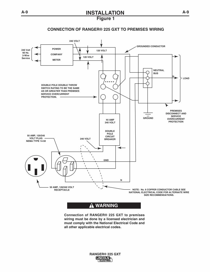
1. Install a double pole, double throw switch betweenthe power company meter and the premises dis-connect.
Switch rating must be the same or greater than thecustomerʼs premises disconnect and service over-current protection.
2. Take necessary steps to assure load is limited tothe capacity of the RANGER® 225 GXT byinstalling a 40 amp 240V double pole circuit break-er. Maximum rated load for the 240V auxiliary is 38amperes. Loading above 38 amperes will reduceoutput voltage below the allowable -10% of ratedvoltage which may damage appliances or othermotor-driven equipment.
3. Install a 50 amp 120/240V plug (NEMA type 14-50)to the Double Pole Circuit Breaker using No. 8, 4conductor cable of the desired length. (The 50 amp120/240V plug is available in the optional plug kit.)
4. Plug this cable into the 50 amp 120/240V recepta-cle on the RANGER® 225 GXT case front.
WARNING
AUXILIARY POWER WHILE WELDING
Simultaneous welding and power loads are permittedby following Table I. The permissible currents shownassume that current is being drawn from either the120V or 240V supply (not both at the same time).Also, the “Output Control” is set at “10” for maximumauxiliary power.
TABLE ISIMULTANEOUS WELDING AND POWER
Output Selector Permissible Power Permissible AuxiliarySetting Watts (Unity Power Current in Amperes
Factor) @ 120V *-or- @ 240V
Max. Stick or WireFeed Setting None 0 0
145 Stick Setting 3450 32** 16
90 Stick Setting 6000 50** 25
No Welding 9000 76** 38
* Each duplex receptacle is limited to 20 amps.
**Not to exceed 40A per 120VAC branch circuit when
splitting the 240 VAC output.
A-9INSTALLATION
RANGER® 225 GXT
A-9
Connection of RANGER® 225 GXT to premiseswiring must be done by a licensed electrician andmust comply with the National Electrical Code andall other applicable electrical codes.
Figure 1
CONNECTION OF RANGER® 225 GXT TO PREMISES WIRING
WARNING

WELDER CONTROLS - FUNCTION ANDOPERATION
ENGINE SWITCHThe engine switch is used to Start the Engine, SelectHigh Idle or Auto Idle while the engine is running, andstop the Engine.
When placed in the “OFF” position, the ignitioncircuit is de-energized to shut down the engine.
When held in the “START” position, the enginestarter motor is energized.
When in “HIGH IDLE” ( ) position, the engine willrun continuously at high idle.
When in “AUTO IDLE” ( / ) position, theengine will run continuously and the idler operates asfollows:
• Welding
When the electrode touches the work, the welding arc is initiated and the engine accelerates to fullspeed.
After welding ceases (and no auxiliary power isbeing drawn), the engine will return to low idleafter approximately 10 to 14 seconds.
• Auxiliary Power
With the engine running at low idle and auxiliarypower for lights or tools is drawn (approximately100-150 watts or greater) from the receptacles,the engine will accelerate to high speed. If nopower is being drawn from the receptacles (andnot welding) for 10-14 seconds, the idler reducesthe engine speed to low idle.
B-1OPERATION
RANGER® 225 GXT
B-1
SAFETY PRECAUTIONS
Do not attempt to use this equipment until youhave thoroughly read the engine manufacturerʼsmanual supplied with your welder. It includesimportant safety precautions, detailed enginestarting, operating and maintenance instructions,and parts lists.------------------------------------------------------------------------
ELECTRIC SHOCK can kill.• Do not touch electrically live parts or
electrode with skin or wet clothing.• Insulate yourself from work and
ground• Always wear dry insulating gloves.
• Always operate the welder with the hinged doorclosed and the side panels in place.
• Read carefully the Safety Precautions pagebefore operating this machine. Always followthese and any other safety procedures includedin this manual and in the Engine InstructionManual.
------------------------------------------------------------------------
GENERAL DESCRIPTIONThe RANGER® 225 GXT is a twin-cylinder, gasolinedriven, multiprocess arc welder and AC power gener-ator. It is built in a heavy gauge steel case for durabili-ty on the job site.
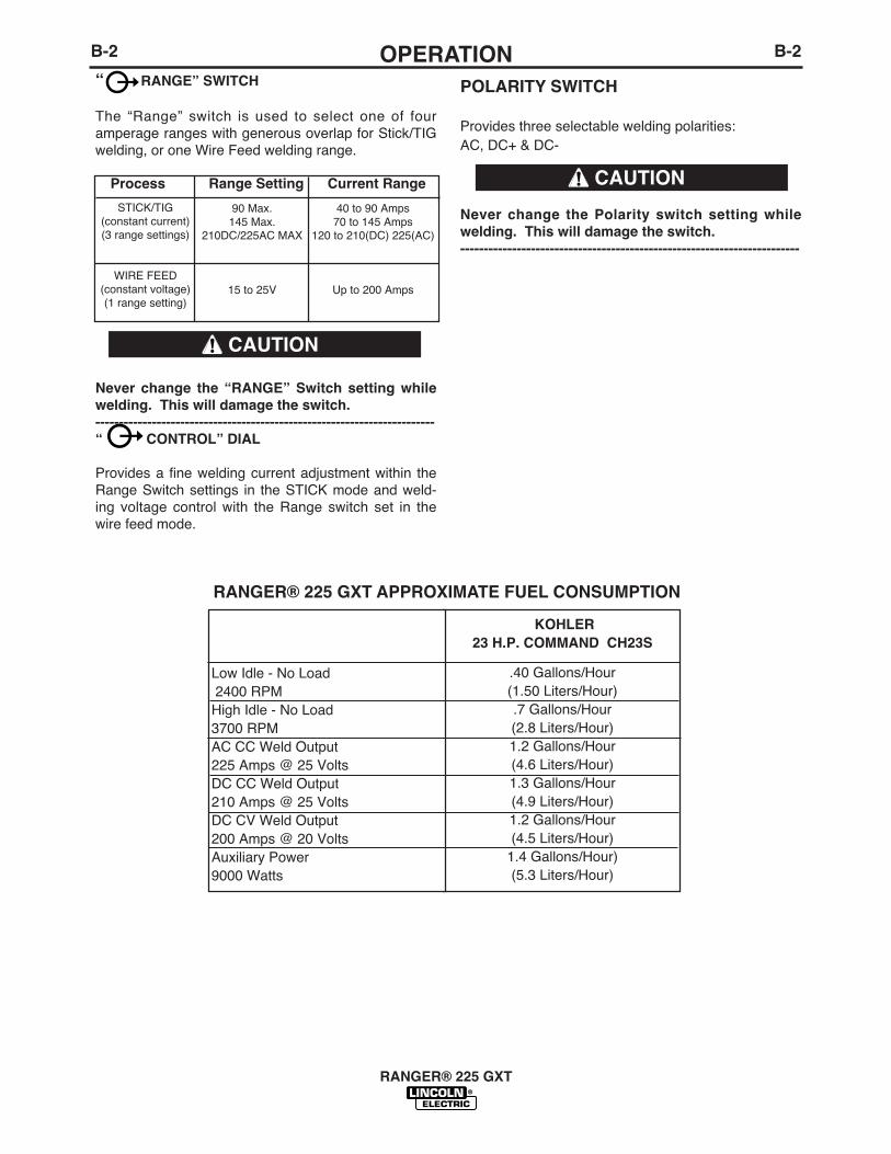
“ RANGE” SWITCH
The “Range” switch is used to select one of fouramperage ranges with generous overlap for Stick/TIGwelding, or one Wire Feed welding range.
Never change the “RANGE” Switch setting whilewelding. This will damage the switch.------------------------------------------------------------------------“ CONTROL” DIAL
Provides a fine welding current adjustment within theRange Switch settings in the STICK mode and weld-ing voltage control with the Range switch set in thewire feed mode.
Process Range Setting Current Range
POLARITY SWITCH
Provides three selectable welding polarities: AC, DC+ & DC-
Never change the Polarity switch setting whilewelding. This will damage the switch.------------------------------------------------------------------------
B-2OPERATIONB-2
RANGER® 225 GXT
CAUTION
CAUTION
KOHLER23 H.P. COMMAND CH23S
.40 Gallons/Hour(1.50 Liters/Hour).7 Gallons/Hour(2.8 Liters/Hour)1.2 Gallons/Hour(4.6 Liters/Hour)1.3 Gallons/Hour(4.9 Liters/Hour)1.2 Gallons/Hour(4.5 Liters/Hour)
1.4 Gallons/Hour)(5.3 Liters/Hour)
Low Idle - No Load2400 RPM
High Idle - No Load3700 RPMAC CC Weld Output225 Amps @ 25 VoltsDC CC Weld Output210 Amps @ 25 VoltsDC CV Weld Output200 Amps @ 20 VoltsAuxiliary Power9000 Watts
RANGER® 225 GXT APPROXIMATE FUEL CONSUMPTION
STICK/TIG (constant current)(3 range settings)
WIRE FEED(constant voltage)(1 range setting)
90 Max.145 Max.
210DC/225AC MAX
15 to 25V
40 to 90 Amps70 to 145 Amps
120 to 210(DC) 225(AC)
Up to 200 Amps

B-3OPERATIONB-3
STARTING/SHUTDOWN INSTRUCTIONSSTARTING THE ENGINE
Be sure all Pre-Operation Maintenance has been per-formed. Also, read the Engine Ownerʼs Manual beforestarting for the first time.
Remove all loads connected to the AC power recepta-cles. Use the choke control as follows:
KOHLER ENGINE - Always pull the choke control outwhen starting the engine; cold, warm or hot.
Turn the engine switch to the “start” position andcrank the engine until it starts. Release the switch assoon as the engine starts, slowly return the chokecontrol to the full “in” position (choke open), and turn the switch to the Auto Idle( / ) position. Do not turn the switch to the “start” positionwhile the engine is running because this will causedamage to the ring gear and/or starter motor
After running at high engine speed for 10-14 seconds,the engine will go to low idle.Allow the engine to warm up by letting it run at low idlefor a few minutes.
STOPPING THE ENGINE
Remove all welding and auxiliary power loads andallow engine to run at low idle speed for a few minutesto cool the engine.
Stop the engine by placing the Engine switch in the
“OFF” position.
A fuel shut off valve is not required on the RANGER®225 GXT because the fuel tank is mounted below theengine.
BREAK-IN PERIOD
It is normal for any engine to use a greater amount ofoil until the break-in is accomplished. Check the oillevel twice a day during the break-in period (approxi-mately 50 running hours).
IMPORTANT: IN ORDER TO ACCOMPLISH THISBREAK-IN, THE UNIT SHOULD BESUBJECTED TO MODERATE LOADS, WITHIN THE RATING OFTHE MACHINE. AVOID LONG IDLERUNNING PERIODS. REMOVE LOADS AND ALLOW ENGINE TO COOL BEFORE SHUTDOWN.
The engine manufacturerʼs recommendation for therunning time until the first oil change is as follows:
The oil filter is to be changed at the second oilchange. Refer to the Engine Ownerʼs Manual for moreinformation.
RANGER® 225 GXT
• Do not touch electrically live partsof electrode with skin or wetclothing.
• Keep flammable material away.
• Insulate yourself from work andground. Wear eye, ear, and bodyprotection.
• Keep your head out of the fumes.
• Use ventilation or exhaust to remove fumes from breathing zone.
WARNING
KOHLERCH23S
5 HRS
B-4OPERATIONB-4
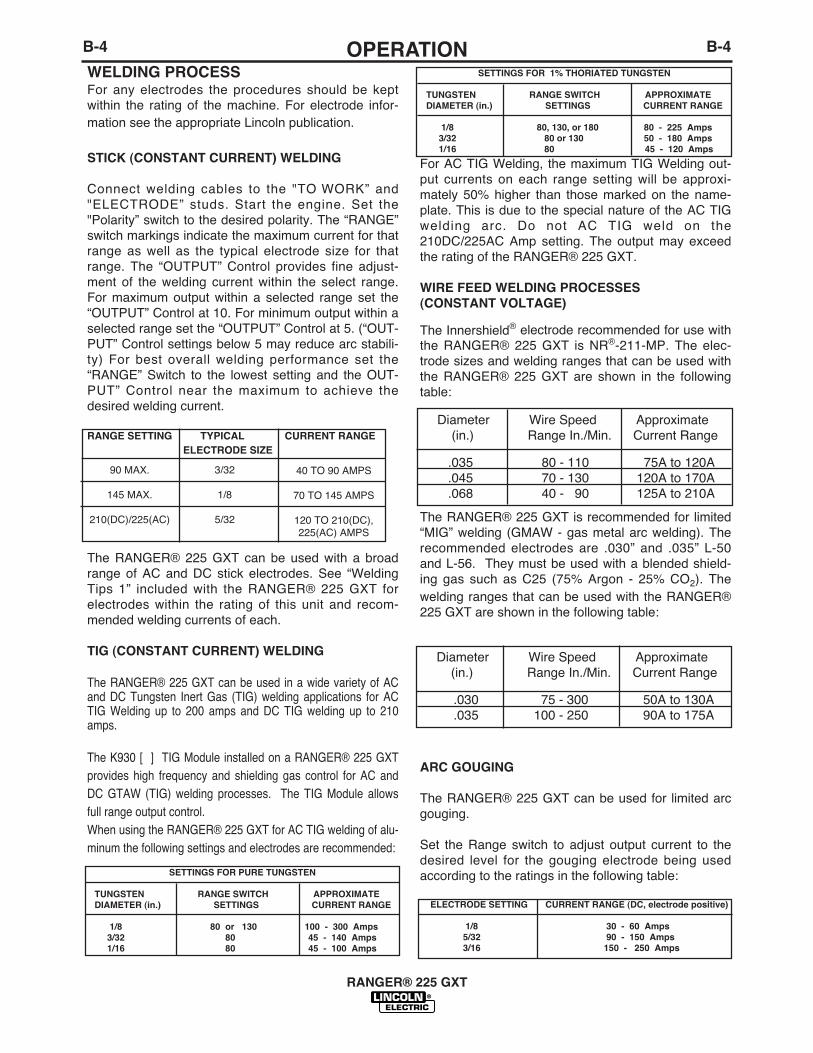
WELDING PROCESSFor any electrodes the procedures should be keptwithin the rating of the machine. For electrode infor-mation see the appropriate Lincoln publication.
STICK (CONSTANT CURRENT) WELDING
Connect welding cables to the "TO WORK” and"ELECTRODE” studs. Start the engine. Set the"Polarity” switch to the desired polarity. The “RANGE”switch markings indicate the maximum current for thatrange as well as the typical electrode size for thatrange. The “OUTPUT” Control provides fine adjust-ment of the welding current within the select range.For maximum output within a selected range set the“OUTPUT” Control at 10. For minimum output within aselected range set the “OUTPUT” Control at 5. (“OUT-PUT” Control settings below 5 may reduce arc stabili-ty) For best overall welding performance set the“RANGE” Switch to the lowest setting and the OUT-PUT” Control near the maximum to achieve thedesired welding current.
RANGE SETTING TYPICAL CURRENT RANGEELECTRODE SIZE
The RANGER® 225 GXT can be used with a broadrange of AC and DC stick electrodes. See “WeldingTips 1” included with the RANGER® 225 GXT forelectrodes within the rating of this unit and recom-mended welding currents of each.
TIG (CONSTANT CURRENT) WELDING
The RANGER® 225 GXT can be used in a wide variety of ACand DC Tungsten Inert Gas (TIG) welding applications for ACTIG Welding up to 200 amps and DC TIG welding up to 210amps.
The K930 [ ] TIG Module installed on a RANGER® 225 GXTprovides high frequency and shielding gas control for AC andDC GTAW (TIG) welding processes. The TIG Module allowsfull range output control. When using the RANGER® 225 GXT for AC TIG welding of alu-minum the following settings and electrodes are recommended:
For AC TIG Welding, the maximum TIG Welding out-put currents on each range setting will be approxi-mately 50% higher than those marked on the name-plate. This is due to the special nature of the AC TIGwelding arc. Do not AC TIG weld on the210DC/225AC Amp setting. The output may exceedthe rating of the RANGER® 225 GXT.
WIRE FEED WELDING PROCESSES(CONSTANT VOLTAGE)
The Innershield® electrode recommended for use withthe RANGER® 225 GXT is NR®-211-MP. The elec-trode sizes and welding ranges that can be used withthe RANGER® 225 GXT are shown in the followingtable:
The RANGER® 225 GXT is recommended for limited“MIG” welding (GMAW - gas metal arc welding). Therecommended electrodes are .030” and .035” L-50and L-56. They must be used with a blended shield-ing gas such as C25 (75% Argon - 25% CO2). Thewelding ranges that can be used with the RANGER®225 GXT are shown in the following table:
ARC GOUGING
The RANGER® 225 GXT can be used for limited arcgouging.
Set the Range switch to adjust output current to thedesired level for the gouging electrode being usedaccording to the ratings in the following table:
RANGER® 225 GXT
Diameter Wire Speed Approximate(in.) Range In./Min. Current Range
.035 80 - 110 75A to 120A
.045 70 - 130 120A to 170A
.068 40 - 90 125A to 210A
Diameter Wire Speed Approximate(in.) Range In./Min. Current Range
.030 75 - 300 50A to 130A
.035 100 - 250 90A to 175A
SETTINGS FOR PURE TUNGSTEN
TUNGSTEN RANGE SWITCH APPROXIMATEDIAMETER (in.) SETTINGS CURRENT RANGE
1/8 80 or 130 100 - 300 Amps3/32 80 45 - 140 Amps1/16 80 45 - 100 Amps
SETTINGS FOR 1% THORIATED TUNGSTEN
TUNGSTEN RANGE SWITCH APPROXIMATEDIAMETER (in.) SETTINGS CURRENT RANGE
1/8 80, 130, or 180 80 - 225 Amps3/32 80 or 130 50 - 180 Amps1/16 80 45 - 120 Amps
ELECTRODE SETTING CURRENT RANGE (DC, electrode positive)
1/8 30 - 60 Amps5/32 90 - 150 Amps3/16 150 - 250 Amps
90 MAX.
145 MAX.
210(DC)/225(AC)
3/32
1/8
5/32
40 TO 90 AMPS
70 TO 145 AMPS
120 TO 210(DC),225(AC) AMPS
B-5OPERATIONB-5
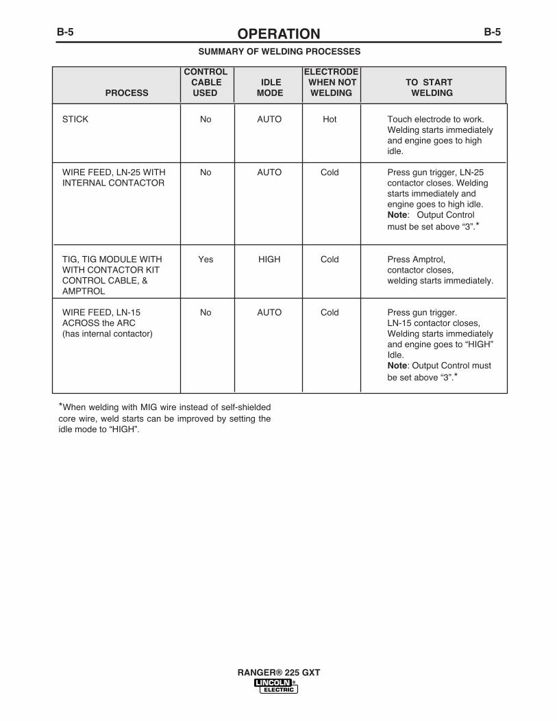
*When welding with MIG wire instead of self-shieldedcore wire, weld starts can be improved by setting theidle mode to “HIGH”.
RANGER® 225 GXT
SUMMARY OF WELDING PROCESSES
CONTROL ELECTRODECABLE IDLE WHEN NOT TO START
PROCESS USED MODE WELDING WELDING
STICK No AUTO Hot Touch electrode to work.Welding starts immediatelyand engine goes to highidle.
WIRE FEED, LN-25 WITH No AUTO Cold Press gun trigger, LN-25INTERNAL CONTACTOR contactor closes. Welding
starts immediately andengine goes to high idle.Note: Output Control must be set above “3”.*
TIG, TIG MODULE WITH Yes HIGH Cold Press Amptrol,WITH CONTACTOR KIT contactor closes,CONTROL CABLE, & welding starts immediately.AMPTROL
WIRE FEED, LN-15 No AUTO Cold Press gun trigger.ACROSS the ARC LN-15 contactor closes,(has internal contactor) Welding starts immediately
and engine goes to “HIGH”Idle.Note: Output Control must be set above “3”.*
C-1ACCESSORIESC-1
RANGER® 225 GXT
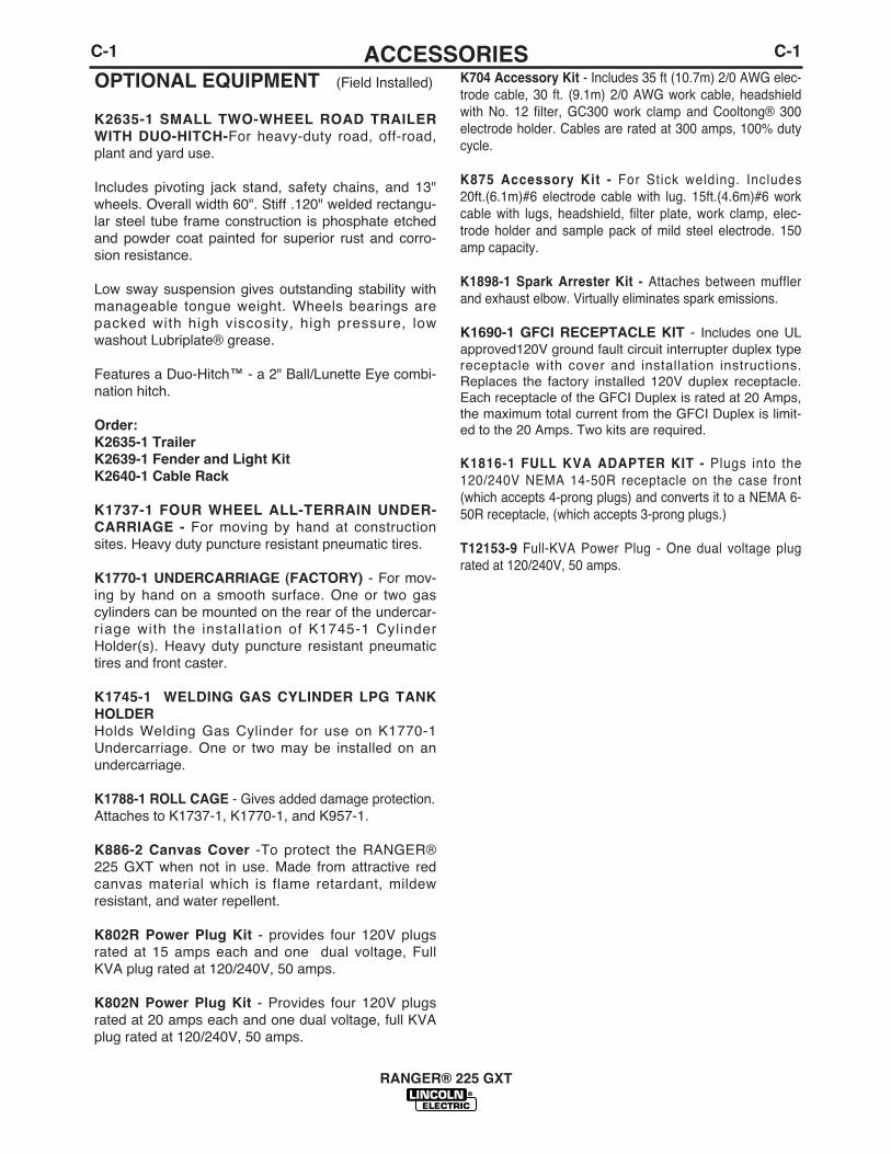
OPTIONAL EQUIPMENT (Field Installed)
K2635-1 SMALL TWO-WHEEL ROAD TRAILERWITH DUO-HITCH-For heavy-duty road, off-road,plant and yard use.
Includes pivoting jack stand, safety chains, and 13"wheels. Overall width 60". Stiff .120" welded rectangu-lar steel tube frame construction is phosphate etchedand powder coat painted for superior rust and corro-sion resistance.
Low sway suspension gives outstanding stability withmanageable tongue weight. Wheels bearings arepacked with high viscosity, high pressure, lowwashout Lubriplate® grease.
Features a Duo-Hitch™ - a 2" Ball/Lunette Eye combi-nation hitch.
Order:K2635-1 TrailerK2639-1 Fender and Light KitK2640-1 Cable Rack
K1737-1 FOUR WHEEL ALL-TERRAIN UNDER-CARRIAGE - For moving by hand at constructionsites. Heavy duty puncture resistant pneumatic tires.
K1770-1 UNDERCARRIAGE (FACTORY) - For mov-ing by hand on a smooth surface. One or two gascylinders can be mounted on the rear of the undercar-riage with the installation of K1745-1 CylinderHolder(s). Heavy duty puncture resistant pneumatictires and front caster.
K1745-1 WELDING GAS CYLINDER LPG TANKHOLDERHolds Welding Gas Cylinder for use on K1770-1Undercarriage. One or two may be installed on anundercarriage.
K1788-1 ROLL CAGE - Gives added damage protection.Attaches to K1737-1, K1770-1, and K957-1.
K886-2 Canvas Cover -To protect the RANGER®225 GXT when not in use. Made from attractive redcanvas material which is flame retardant, mildewresistant, and water repellent.
K802R Power Plug Kit - provides four 120V plugsrated at 15 amps each and one dual voltage, FullKVA plug rated at 120/240V, 50 amps.
K802N Power Plug Kit - Provides four 120V plugsrated at 20 amps each and one dual voltage, full KVAplug rated at 120/240V, 50 amps.
K704 Accessory Kit - Includes 35 ft (10.7m) 2/0 AWG elec-trode cable, 30 ft. (9.1m) 2/0 AWG work cable, headshieldwith No. 12 filter, GC300 work clamp and Cooltong® 300electrode holder. Cables are rated at 300 amps, 100% dutycycle.
K875 Accessory Kit - For Stick welding. Includes20ft.(6.1m)#6 electrode cable with lug. 15ft.(4.6m)#6 workcable with lugs, headshield, filter plate, work clamp, elec-trode holder and sample pack of mild steel electrode. 150amp capacity.
K1898-1 Spark Arrester Kit - Attaches between mufflerand exhaust elbow. Virtually eliminates spark emissions.
K1690-1 GFCI RECEPTACLE KIT - Includes one ULapproved120V ground fault circuit interrupter duplex typereceptacle with cover and installation instructions.Replaces the factory installed 120V duplex receptacle.Each receptacle of the GFCI Duplex is rated at 20 Amps,the maximum total current from the GFCI Duplex is limit-ed to the 20 Amps. Two kits are required.
K1816-1 FULL KVA ADAPTER KIT - Plugs into the120/240V NEMA 14-50R receptacle on the case front(which accepts 4-prong plugs) and converts it to a NEMA 6-50R receptacle, (which accepts 3-prong plugs.)
T12153-9 Full-KVA Power Plug - One dual voltage plugrated at 120/240V, 50 amps.
C-2ACCESSORIESC-2
RANGER® 225 GXT
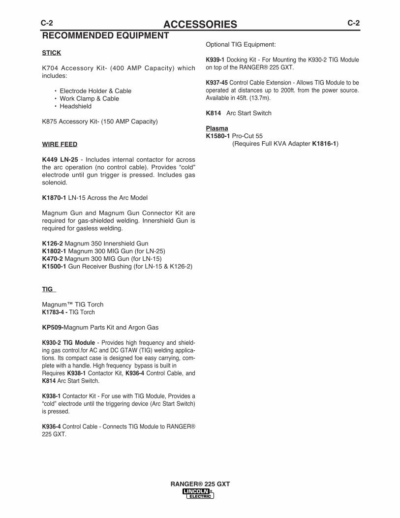
RECOMMENDED EQUIPMENT
STICK
K704 Accessory Kit- (400 AMP Capacity) whichincludes:
• Electrode Holder & Cable• Work Clamp & Cable• Headshield
K875 Accessory Kit- (150 AMP Capacity)
WIRE FEED
K449 LN-25 - Includes internal contactor for acrossthe arc operation (no control cable). Provides “cold”electrode until gun trigger is pressed. Includes gassolenoid.
K1870-1 LN-15 Across the Arc Model
Magnum Gun and Magnum Gun Connector Kit arerequired for gas-shielded welding. Innershield Gun isrequired for gasless welding.
K126-2 Magnum 350 Innershield GunK1802-1 Magnum 300 MIG Gun (for LN-25)K470-2 Magnum 300 MIG Gun (for LN-15)K1500-1 Gun Receiver Bushing (for LN-15 & K126-2)
TIG
Magnum™ TIG TorchK1783-4 - TIG Torch
KP509-Magnum Parts Kit and Argon Gas
K930-2 TIG Module - Provides high frequency and shield-ing gas control.for AC and DC GTAW (TIG) welding applica-tions. Its compact case is designed foe easy carrying, com-plete with a handle. High frequency bypass is built inRequires K938-1 Contactor Kit, K936-4 Control Cable, andK814 Arc Start Switch.
K938-1 Contactor Kit - For use with TIG Module, Provides a“cold” electrode until the triggering device (Arc Start Switch)is pressed.
K936-4 Control Cable - Connects TIG Module to RANGER®225 GXT.
Optional TIG Equipment:
K939-1 Docking Kit - For Mounting the K930-2 TIG Moduleon top of the RANGER® 225 GXT.
K937-45 Control Cable Extension - Allows TIG Module to beoperated at distances up to 200ft. from the power source.Available in 45ft. (13.7m).
K814 Arc Start Switch
PlasmaK1580-1 Pro-Cut 55
(Requires Full KVA Adapter K1816-1)
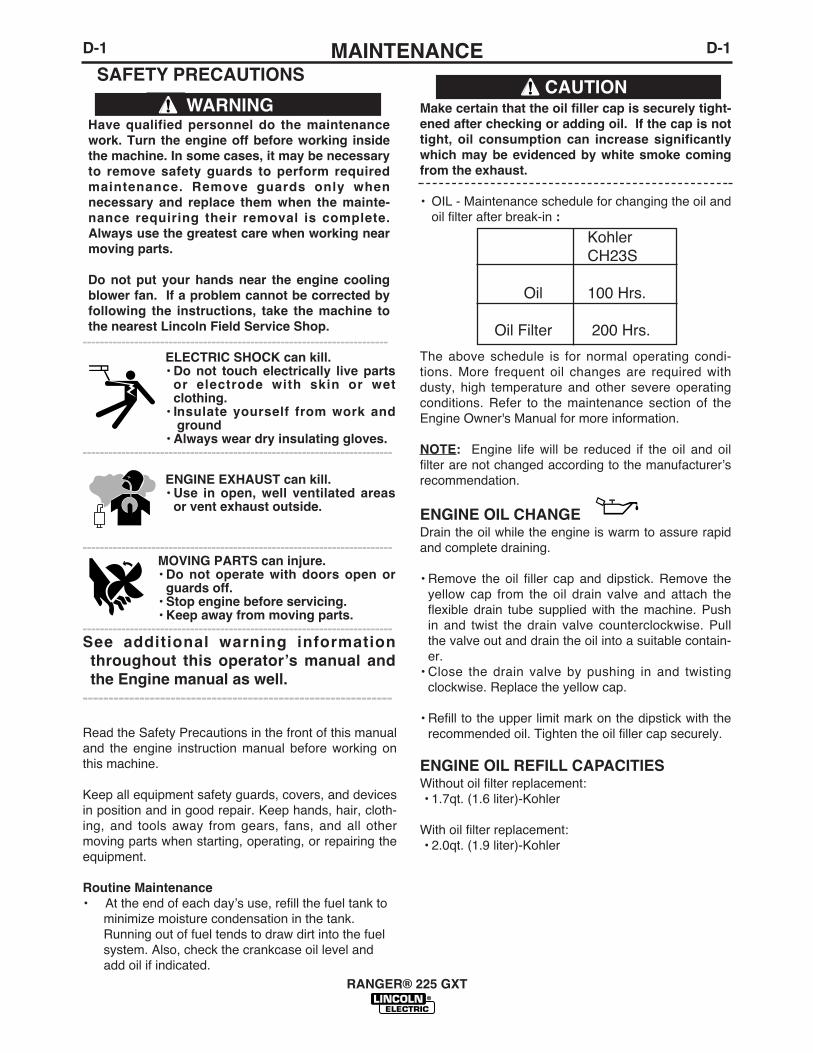
Have qualified personnel do the maintenancework. Turn the engine off before working insidethe machine. In some cases, it may be necessaryto remove safety guards to perform requiredmaintenance. Remove guards only whennecessary and replace them when the mainte-nance requiring their removal is complete.Always use the greatest care when working nearmoving parts.
Do not put your hands near the engine coolingblower fan. If a problem cannot be corrected byfollowing the instructions, take the machine tothe nearest Lincoln Field Service Shop.
-----------------------------------------------------------------------ELECTRIC SHOCK can kill.• Do not touch electrically live parts
or electrode with skin or wetclothing.
• Insulate yourself from work andground
• Always wear dry insulating gloves.------------------------------------------------------------------------
ENGINE EXHAUST can kill.• Use in open, well ventilated areas
or vent exhaust outside.
------------------------------------------------------------------------MOVING PARTS can injure.• Do not operate with doors open or
guards off.• Stop engine before servicing.• Keep away from moving parts.
------------------------------------------------------------------------See additional warning informationthroughout this operatorʼs manual andthe Engine manual as well.
------------------------------------------------------------
Make certain that the oil filler cap is securely tight-ened after checking or adding oil. If the cap is nottight, oil consumption can increase significantlywhich may be evidenced by white smoke comingfrom the exhaust.
• OIL - Maintenance schedule for changing the oil andoil filter after break-in :
The above schedule is for normal operating condi-tions. More frequent oil changes are required withdusty, high temperature and other severe operatingconditions. Refer to the maintenance section of theEngine Owner's Manual for more information.
NOTE: Engine life will be reduced if the oil and oilfilter are not changed according to the manufacturerʼsrecommendation.
ENGINE OIL CHANGE Drain the oil while the engine is warm to assure rapidand complete draining.
• Remove the oil filler cap and dipstick. Remove theyellow cap from the oil drain valve and attach theflexible drain tube supplied with the machine. Pushin and twist the drain valve counterclockwise. Pullthe valve out and drain the oil into a suitable contain-er.
• Close the drain valve by pushing in and twistingclockwise. Replace the yellow cap.
• Refill to the upper limit mark on the dipstick with therecommended oil. Tighten the oil filler cap securely.
ENGINE OIL REFILL CAPACITIESWithout oil filter replacement:• 1.7qt. (1.6 liter)-Kohler
With oil filter replacement:• 2.0qt. (1.9 liter)-Kohler
WARNING
D-1MAINTENANCED-1
RANGER® 225 GXT
SAFETY PRECAUTIONSCAUTION
Read the Safety Precautions in the front of this manualand the engine instruction manual before working onthis machine.
Keep all equipment safety guards, covers, and devicesin position and in good repair. Keep hands, hair, cloth-ing, and tools away from gears, fans, and all othermoving parts when starting, operating, or repairing theequipment.
Routine Maintenance• At the end of each dayʼs use, refill the fuel tank to
minimize moisture condensation in the tank.Running out of fuel tends to draw dirt into the fuel system. Also, check the crankcase oil level andadd oil if indicated.
KohlerCH23S
Oil 100 Hrs.
Oil Filter 200 Hrs.

D-2MAINTENANCED-2
Use 4-stroke motor oil that meets or exceeds therequirements for API service classification SG or SH.Always check the API SERVICE label on the oil con-tainer to be sure it includes the letters SG or SH.
SAE 10W-30 is recommended for general, all-tempera-ture use, -5 F to 104 F (-20 C to 40 C).
See Engine Ownerʼs Manual for more specific informa-tion on oil viscosity recommendations.
Wash your hands with soap and water after handlingused oil.
Please dispose of used motor oil in a manner that iscompatible with the environment. We suggest you takeit in a sealed container to your local service station orrecycling center for reclamation.
Do not throw it in the trash, pour it on the ground ordown a drain.
OIL FILTER CHANGE
1. Drain the engine oil.
2. Remove the oil filter, and drain the oil into a suitablecontainer. Discard the used oil filter.
3. Clean the filter mounting base, and coat the gasketof the new oil filter with clean engine oil.
4. Screw on the new oil filter by hand, until the gasketcontacts the filter mounting base, then use an oil fil-ter socket tool to tighten the filter an additional 1/2 to7/8 turn.
5. Refill the crankcase with the specified amount of therecommended oil. Reinstall the oil filler cap.
6. Start the engine and check for oil filter leaks.
7. Stop the engine, and check the oil level. If neces-sary, add oil to the upper limit mark on the dipstick.
AIR CLEANER AND OTHER MAINTENANCE
• Air Cleaner - With normal operating conditions, themaintenance schedule for cleaning and re-oilingthe foam pre-filter is every 25 hours and replace-ment of the air cleaner filter every 100 hours.More frequent servicing is required with dustyoperating conditions. Refer to the maintenancesection of the Engine Ownerʼs Manual for moreinformation.
• Refer to the maintenance section of the EngineOwnerʼs Manual for the maintenance schedule,spark plug servicing, cooling system servicing, andfuel filter replacement.
• Blow out the machine with low pressure air period-ically. In particularly dirty locations, this may berequired once a week.
• Output Ranger Selector and Polarity Switches:Switch contacts should not be greased. To keepcontacts clean, rotate the switch through its entirerange frequently. Good practice is to turn the han-dle from maximum to minimum setting twice eachmorning before starting to weld.
RANGER® 225 GXT
D-3MAINTENANCED-3
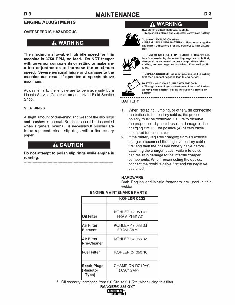
ENGINE ADJUSTMENTS
OVERSPEED IS HAZARDOUS
The maximum allowable high idle speed for thismachine is 3750 RPM, no load. Do NOT tamperwith governor components or setting or make anyother adjustments to increase the maximumspeed. Severe personal injury and damage to themachine can result if operated at speeds abovemaximum.------------------------------------------------------------------------Adjustments to the engine are to be made only by aLincoln Service Center or an authorized Field ServiceShop.
SLIP RINGS
A slight amount of darkening and wear of the slip ringsand brushes is normal. Brushes should be inspectedwhen a general overhaul is necessary.If brushes areto be replaced, clean slip rings with a fine emerypaper.
Do not attempt to polish slip rings while engine isrunning.------------------------------------------------------------------------
BATTERY
1. When replacing, jumping, or otherwise connectingthe battery to the battery cables, the properpolarity must be observed. Failure to observethe proper polarity could result in damage to thecharging circuit. The positive (+) battery cablehas a red terminal cover.
2. If the battery requires charging from an external charger, disconnect the negative battery cablefirst and then the positive battery cable beforeattaching the charger leads. Failure to do socan result in damage to the internal chargercomponents. When reconnecting the cables,connect the positive cable first and the negativecable last.
HARDWAREBoth English and Metric fasteners are used in thiswelder.
RANGER® 225 GXT
WARNING
GASES FROM BATTERY can explode.• Keep sparks, flame and cigarettes away from battery.
To prevent EXPLOSION when:• INSTALLING A NEW BATTERY - disconnect negativecable from old battery first and connect to new batterylast.
• CONNECTING A BATTERY CHARGER - Remove bat-tery from welder by disconnecting negative cable first,then positive cable and battery clamp. When rein-stalling, connect negative cable last. Keep well venti-lated.
• USING A BOOSTER - connect positive lead to batteryfirst then connect negative lead to engine foot.
BATTERY ACID CAN BURN EYES AND SKIN.• Wear gloves and eye protection and be careful whenworking near battery. Follow instructions printed onbattery.
WARNING
CAUTION
KOHLER C23S
KOHLER 12 050 01Oil Filter FRAM PH8172*
Air Filter KOHLER 47 083 03Element FRAM CA79
Air Filter KOHLER 24 083 02Pre-Cleaner
Fuel Filter KOHLER 24 050 10
Spark Plugs CHAMPION RC12YC(Resistor (.030” GAP)
Type)
* Oil capacity increases from 2.0 Qts. to 2.1 Qts. when using this filter.
ENGINE MAINTENANCE PARTS

E-1TROUBLESHOOTINGE-1
RANGER® 225 GXT
If for any reason you do not understand the test procedures or are unable to perform the tests/repairs safely, contact yourLocal Lincoln Authorized Field Service Facility for technical troubleshooting assistance before you proceed.
CAUTION
This Troubleshooting Guide is provided to help youlocate and repair possible machine malfunctions.Simply follow the three-step procedure listed below.
Step 1. LOCATE PROBLEM (SYMPTOM).Look under the column labeled “PROBLEM (SYMP-TOMS)”. This column describes possible symptomsthat the machine may exhibit. Find the listing thatbest describes the symptom that the machine isexhibiting.
Step 2. POSSIBLE CAUSE.The second column labeled “POSSIBLE CAUSE” liststhe obvious external possibilities that may contributeto the machine symptom.
Step 3. RECOMMENDED COURSE OF ACTIONThis column provides a course of action for thePossible Cause, generally it states to contact yourlocal Lincoln Authorized Field Service Facility.
If you do not understand or are unable to perform theRecommended Course of Action safely, contact yourlocal Lincoln Authorized Field Service Facility.
HOW TO USE TROUBLESHOOTING GUIDE
Service and Repair should only be performed by Lincoln Electric Factory Trained Personnel.Unauthorized repairs performed on this equipment may result in danger to the technician andmachine operator and will invalidate your factory warranty. For your safety and to avoid ElectricalShock, please observe all safety notes and precautions detailed throughout this manual.
__________________________________________________________________________
WARNING
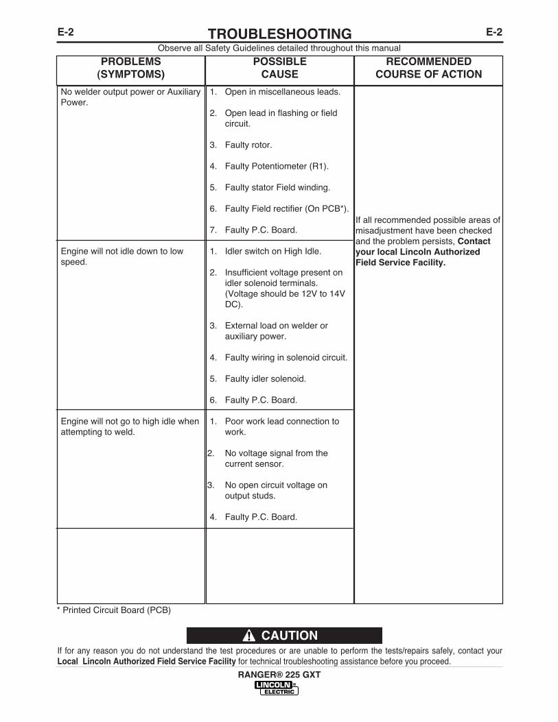
E-2TROUBLESHOOTINGE-2
RANGER® 225 GXT
Observe all Safety Guidelines detailed throughout this manual
If for any reason you do not understand the test procedures or are unable to perform the tests/repairs safely, contact yourLocal Lincoln Authorized Field Service Facility for technical troubleshooting assistance before you proceed.
CAUTION
PROBLEMS(SYMPTOMS)
POSSIBLE CAUSE
RECOMMENDEDCOURSE OF ACTION
No welder output power or AuxiliaryPower.
Engine will not idle down to lowspeed.
Engine will not go to high idle whenattempting to weld.
1. Open in miscellaneous leads.
2. Open lead in flashing or fieldcircuit.
3. Faulty rotor.
4. Faulty Potentiometer (R1).
5. Faulty stator Field winding.
6. Faulty Field rectifier (On PCB*).
7. Faulty P.C. Board.
1. Idler switch on High Idle.
2. Insufficient voltage present onidler solenoid terminals.(Voltage should be 12V to 14VDC).
3. External load on welder orauxiliary power.
4. Faulty wiring in solenoid circuit.
5. Faulty idler solenoid.
6. Faulty P.C. Board.
1. Poor work lead connection towork.
2. No voltage signal from thecurrent sensor.
3. No open circuit voltage on output studs.
4. Faulty P.C. Board.
If all recommended possible areas ofmisadjustment have been checkedand the problem persists, Contactyour local Lincoln AuthorizedField Service Facility.
* Printed Circuit Board (PCB)
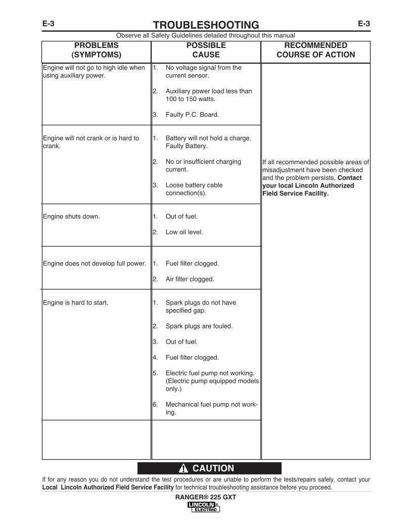
E-3TROUBLESHOOTINGE-3
RANGER® 225 GXT
Observe all Safety Guidelines detailed throughout this manual
If for any reason you do not understand the test procedures or are unable to perform the tests/repairs safely, contact yourLocal Lincoln Authorized Field Service Facility for technical troubleshooting assistance before you proceed.
CAUTION
PROBLEMS(SYMPTOMS)
POSSIBLE CAUSE
RECOMMENDEDCOURSE OF ACTION
Engine will not go to high idle whenusing auxiliary power.
Engine will not crank or is hard tocrank.
Engine shuts down.
Engine does not develop full power.
Engine is hard to start.
1. No voltage signal from thecurrent sensor.
2. Auxiliary power load less than100 to 150 watts.
3. Faulty P.C. Board.
1. Battery will not hold a charge.Faulty Battery.
2. No or insufficient chargingcurrent.
3. Loose battery cableconnection(s).
1. Out of fuel.
2. Low oil level.
1. Fuel filter clogged.
2. Air filter clogged.
1. Spark plugs do not havespecified gap.
2. Spark plugs are fouled.
3. Out of fuel.
4. Fuel filter clogged.
5. Electric fuel pump not working.(Electric pump equipped modelsonly.)
6. Mechanical fuel pump not work-ing.
If all recommended possible areas ofmisadjustment have been checkedand the problem persists, Contactyour local Lincoln AuthorizedField Service Facility.
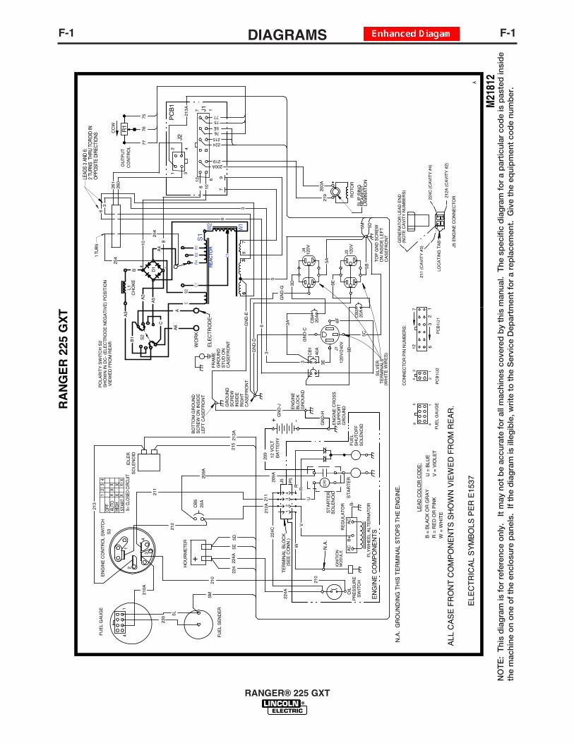
F-1DIAGRAMSF-1
RANGER® 225 GXT
NO
TE
: T
his
dia
gra
m is
fo
r re
fere
nce
onl
y.
It m
ay n
ot
be
accu
rate
fo
r al
l mac
hine
s co
vere
d b
y th
is m
anua
l. T
he s
pec
ific
dia
gra
m f
or
a p
artic
ular
co
de
is p
aste
d in
sid
eth
e m
achi
ne o
n o
ne o
f th
e en
clo
sure
pan
els.
If
the
dia
gra
m is
ille
gib
le, w
rite
to
the
Ser
vice
Dep
artm
ent
for
a re
pla
cem
ent.
Giv
e th
e eq
uip
men
t co
de
num
ber
.
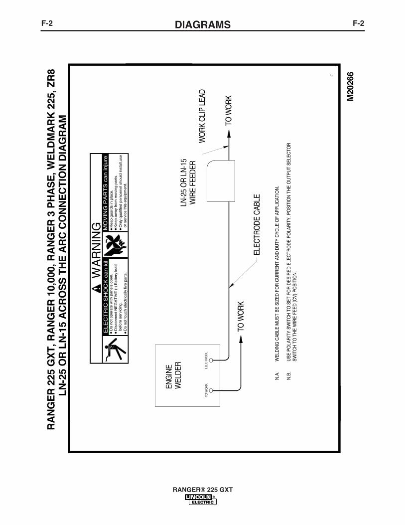
F-2DIAGRAMSF-2
RANGER® 225 GXT
M20
266C
RA
NG
ER
225
GX
T, R
AN
GE
R 1
0,00
0, R
AN
GE
R 3
PH
AS
E, W
EL
DM
AR
K 2
25, Z
R8
LN
-25
OR
LN
-15
AC
RO
SS
TH
E A
RC
CO
NN
EC
TIO
N D
IAG
RA
M
TO W
OR
KEL
ECTR
OD
E
TO W
ORK
TO W
ORK
ELEC
TRO
DE C
ABLE
WO
RK C
LIP
LEAD
N.A
.W
ELD
ING
CAB
LE M
UST
BE
SIZE
D F
OR
CU
RR
ENT
AND
DU
TY C
YCLE
OF
APPL
ICAT
ION
. N
.B.
USE
PO
LAR
ITY
SWIT
CH
TO
SET
FO
R D
ESIR
ED E
LEC
TRO
DE
POLA
RIT
Y. P
OSI
TIO
N T
HE
OU
TPU
T SE
LEC
TOR
SWIT
CH
TO
TH
E W
IRE
FEED
(CV)
PO
SITI
ON
.
ELE
CT
RIC
SH
OC
K c
an k
illD
o no
t ope
rate
with
pan
els
open
.D
isco
nnec
t NE
GA
TIV
E (
-) B
atte
ry le
adbe
fore
ser
vici
ng.
Do
not t
ouch
ele
ctric
ally
live
par
ts.W
AR
NIN
G MO
VIN
G P
AR
TS
can in
jure
Kee
p gu
ards
in p
lace
.K
eep
away
from
mov
ing
part
s.O
nly
qual
ified
per
sonn
el s
houl
d in
stal
l,use
or s
ervi
ce th
is e
quip
men
t.
LN-2
5 O
R LN
-15
WIR
E FE
EDER
ENG
INE
WEL
DER
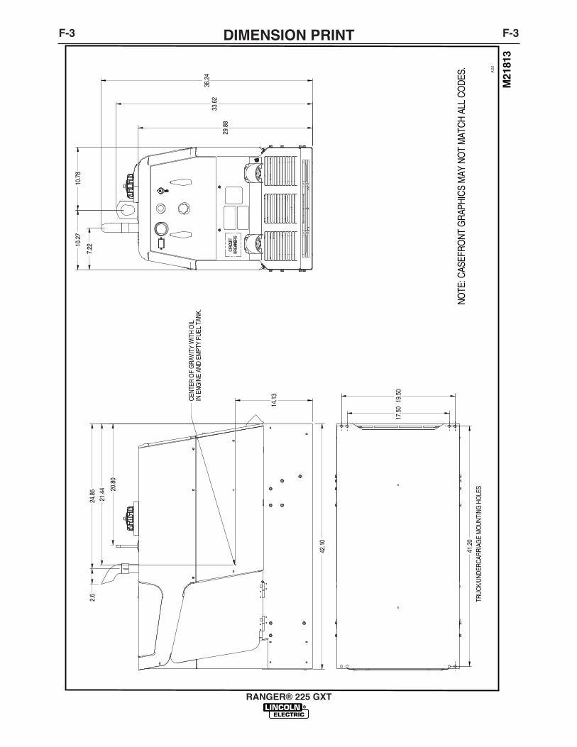
F-3DIMENSION PRINTF-3
RANGER® 225 GXT
M21
813
A.02
CIRC
UCUIT
BRE A
KEAKER
S
41.2
0
17.5
019
.50
14.1
3
TRUC
K/UN
DERC
ARRI
AGE
MO
UNTI
NG H
OLE
S
24.8
62.
67.
22
29.8
8
CENT
ER O
F G
RAVI
TY W
ITH
OIL
IN E
NGIN
E AN
D EM
PTY
FUEL
TAN
K.
21.4
4 20.8
0
42.1
0
33.6
236
.24
10.2
710
.78
NOTE
: CAS
EFRO
NT G
RAPH
ICS
MAY
NO
T M
ATCH
ALL
CO
DES.

NOTES
RANGER® 225 GXT
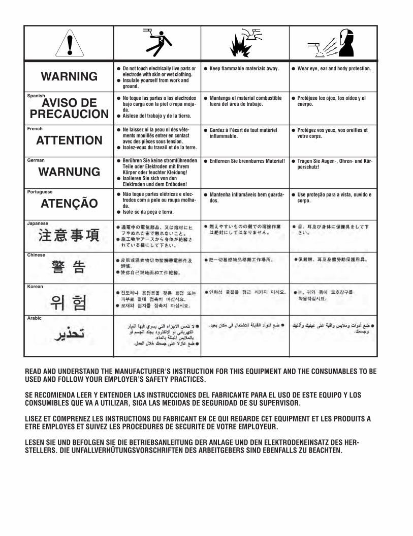
WARNING
AVISO DEPRECAUCION
ATTENTION
WARNUNG
ATENÇÃO
Spanish
French
German
Portuguese
Japanese
Chinese
Korean
Arabic
READ AND UNDERSTAND THE MANUFACTURER’S INSTRUCTION FOR THIS EQUIPMENT AND THE CONSUMABLES TO BEUSED AND FOLLOW YOUR EMPLOYER’S SAFETY PRACTICES.
SE RECOMIENDA LEER Y ENTENDER LAS INSTRUCCIONES DEL FABRICANTE PARA EL USO DE ESTE EQUIPO Y LOSCONSUMIBLES QUE VA A UTILIZAR, SIGA LAS MEDIDAS DE SEGURIDAD DE SU SUPERVISOR.
LISEZ ET COMPRENEZ LES INSTRUCTIONS DU FABRICANT EN CE QUI REGARDE CET EQUIPMENT ET LES PRODUITS AETRE EMPLOYES ET SUIVEZ LES PROCEDURES DE SECURITE DE VOTRE EMPLOYEUR.
LESEN SIE UND BEFOLGEN SIE DIE BETRIEBSANLEITUNG DER ANLAGE UND DEN ELEKTRODENEINSATZ DES HER-STELLERS. DIE UNFALLVERHÜTUNGSVORSCHRIFTEN DES ARBEITGEBERS SIND EBENFALLS ZU BEACHTEN.
● Do not touch electrically live parts orelectrode with skin or wet clothing.
● Insulate yourself from work andground.
● No toque las partes o los electrodosbajo carga con la piel o ropa moja-da.
● Aislese del trabajo y de la tierra.
● Ne laissez ni la peau ni des vête-ments mouillés entrer en contactavec des pièces sous tension.
● Isolez-vous du travail et de la terre.
● Berühren Sie keine stromführendenTeile oder Elektroden mit IhremKörper oder feuchter Kleidung!
● Isolieren Sie sich von denElektroden und dem Erdboden!
● Não toque partes elétricas e elec-trodos com a pele ou roupa molha-da.
● Isole-se da peça e terra.
● Keep flammable materials away.
● Mantenga el material combustiblefuera del área de trabajo.
● Gardez à l’écart de tout matérielinflammable.
● Entfernen Sie brennbarres Material!
● Mantenha inflamáveis bem guarda-dos.
● Wear eye, ear and body protection.
● Protéjase los ojos, los oídos y elcuerpo.
● Protégez vos yeux, vos oreilles etvotre corps.
● Tragen Sie Augen-, Ohren- und Kör-perschutz!
● Use proteção para a vista, ouvido ecorpo.
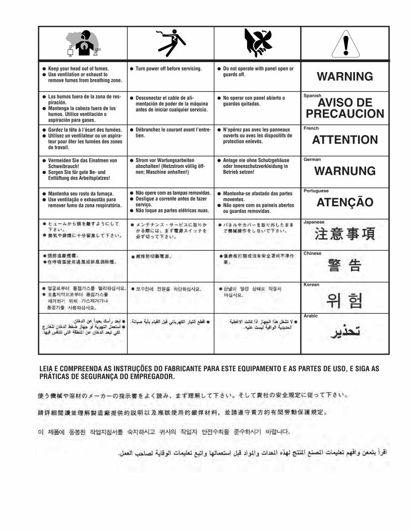
WARNING
AVISO DEPRECAUCION
ATTENTION
WARNUNG
ATENÇÃO
Spanish
French
German
Portuguese
Japanese
Chinese
Korean
Arabic
LEIA E COMPREENDA AS INSTRUÇÕES DO FABRICANTE PARA ESTE EQUIPAMENTO E AS PARTES DE USO, E SIGA ASPRÁTICAS DE SEGURANÇA DO EMPREGADOR.
● Keep your head out of fumes.● Use ventilation or exhaust to
remove fumes from breathing zone.
● Los humos fuera de la zona de res-piración.
● Mantenga la cabeza fuera de loshumos. Utilice ventilación oaspiración para gases.
● Gardez la tête à l’écart des fumées.● Utilisez un ventilateur ou un aspira-
teur pour ôter les fumées des zonesde travail.
● Vermeiden Sie das Einatmen vonSchweibrauch!
● Sorgen Sie für gute Be- undEntlüftung des Arbeitsplatzes!
● Mantenha seu rosto da fumaça.● Use ventilação e exhaustão para
remover fumo da zona respiratória.
● Turn power off before servicing.
● Desconectar el cable de ali-mentación de poder de la máquinaantes de iniciar cualquier servicio.
● Débranchez le courant avant l’entre-tien.
● Strom vor Wartungsarbeitenabschalten! (Netzstrom völlig öff-nen; Maschine anhalten!)
● Não opere com as tampas removidas.● Desligue a corrente antes de fazer
serviço.● Não toque as partes elétricas nuas.
● Do not operate with panel open orguards off.
● No operar con panel abierto oguardas quitadas.
● N’opérez pas avec les panneauxouverts ou avec les dispositifs deprotection enlevés.
● Anlage nie ohne Schutzgehäuseoder Innenschutzverkleidung inBetrieb setzen!
● Mantenha-se afastado das partesmoventes.
● Não opere com os paineis abertosou guardas removidas.

• Sales and Service through Subsidiaries and Distributors Worldwide •
Cleveland, Ohio 44117-1199 U.S.A. TEL: 216.481.8100 FAX: 216.486.1751 WEB SITE: www.lincolnelectric.com
• World's Leader in Welding and Cutting Products •