Embed Size (px)
Citation preview

Ranger 250
OPERATOR’S MANUAL
IM741-AApril, 2003
Safety Depends on YouLincoln arc welding and cuttingequipment is designed and builtwith safety in mind. However, youroverall safety can be increased byproper installation ... and thought-ful operation on your part. DONOT INSTALL, OPERATE ORREPAIR THIS EQUIPMENTWITHOUT READING THISMANUAL AND THE SAFETYPRECAUTIONS CONTAINEDTHROUGHOUT. And, mostimportantly, think before you actand be careful.
For use with machines having Code Numbers: 10795; 10854; 10953; 10954
• Sales and Service through Subsidiaries and Distributors Worldwide •
Cleveland, Ohio 44117-1199 U.S.A. TEL: 216.481.8100 FAX: 216.486.1751 WEB SITE: www.lincolnelectric.com
• World's Leader in Welding and Cutting Products •
Copyright © 2003 Lincoln Global Inc.
This manual covers equipment which is no longer in production by The Lincoln Electric Co. Speci�cations and availability of optional features may have changed.

FOR ENGINEpowered equipment.
1.a. Turn the engine off before troubleshooting and maintenancework unless the maintenance work requires it to be running.
____________________________________________________1.b. Operate engines in open, well-ventilated
areas or vent the engine exhaust fumes outdoors.
____________________________________________________1.c. Do not add the fuel near an open flame
welding arc or when the engine is running.Stop the engine and allow it to cool beforerefueling to prevent spilled fuel from vaporiz-ing on contact with hot engine parts andigniting. Do not spill fuel when filling tank. Iffuel is spilled, wipe it up and do not startengine until fumes have been eliminated.
____________________________________________________1.d. Keep all equipment safety guards, covers and devices in
position and in good repair.Keep hands, hair, clothing andtools away from V-belts, gears, fans and all other movingparts when starting, operating or repairing equipment.
____________________________________________________
1.e. In some cases it may be necessary to remove safetyguards to perform required maintenance. Removeguards only when necessary and replace them when themaintenance requiring their removal is complete.Always use the greatest care when working near movingparts.
___________________________________________________1.f. Do not put your hands near the engine fan.
Do not attempt to override the governor oridler by pushing on the throttle control rodswhile the engine is running.
___________________________________________________1.g. To prevent accidentally starting gasoline engines while
turning the engine or welding generator during maintenancework, disconnect the spark plug wires, distributor cap ormagneto wire as appropriate.
iSAFETYi
ARC WELDING CAN BE HAZARDOUS. PROTECT YOURSELF AND OTHERS FROM POSSIBLE SERIOUS INJURY OR DEATH.KEEP CHILDREN AWAY. PACEMAKER WEARERS SHOULD CONSULT WITH THEIR DOCTOR BEFORE OPERATING.
Read and understand the following safety highlights. For additional safety information, it is strongly recommended that youpurchase a copy of “Safety in Welding & Cutting - ANSI Standard Z49.1” from the American Welding Society, P.O. Box351040, Miami, Florida 33135 or CSA Standard W117.2-1974. A Free copy of “Arc Welding Safety” booklet E205 is availablefrom the Lincoln Electric Company, 22801 St. Clair Avenue, Cleveland, Ohio 44117-1199.
BE SURE THAT ALL INSTALLATION, OPERATION, MAINTENANCE AND REPAIR PROCEDURES AREPERFORMED ONLY BY QUALIFIED INDIVIDUALS.
WARNING
Mar ‘95
ELECTRIC AND MAGNETIC FIELDSmay be dangerous
2.a. Electric current flowing through any conductor causes localized Electric and Magnetic Fields (EMF). Welding current creates EMF fields around welding cables and welding machines
2.b. EMF fields may interfere with some pacemakers, andwelders having a pacemaker should consult their physicianbefore welding.
2.c. Exposure to EMF fields in welding may have other healtheffects which are now not known.
2.d. All welders should use the following procedures in order tominimize exposure to EMF fields from the welding circuit:
2.d.1. Route the electrode and work cables together - Securethem with tape when possible.
2.d.2. Never coil the electrode lead around your body.
2.d.3. Do not place your body between the electrode andwork cables. If the electrode cable is on your right side, the work cable should also be on your right side.
2.d.4. Connect the work cable to the workpiece as close aspossible to the area being welded.
2.d.5. Do not work next to welding power source.
1.h. To avoid scalding, do not remove theradiator pressure cap when the engine ishot.
CALIFORNIA PROPOSITION 65 WARNINGS
Diesel engine exhaust and some of its constituentsare known to the State of California to cause can-cer, birth defects, and other reproductive harm.
The engine exhaust from this product containschemicals known to the State of California to causecancer, birth defects, or other reproductive harm.
The Above For Diesel Engines The Above For Gasoline Engines

iiSAFETYii
ARC RAYS can burn.4.a. Use a shield with the proper filter and cover
plates to protect your eyes from sparks andthe rays of the arc when welding or observingopen arc welding. Headshield and filter lensshould conform to ANSI Z87. I standards.
4.b. Use suitable clothing made from durable flame-resistantmaterial to protect your skin and that of your helpers fromthe arc rays.
4.c. Protect other nearby personnel with suitable, non-flammablescreening and/or warn them not to watch the arc nor exposethemselves to the arc rays or to hot spatter or metal.
ELECTRIC SHOCK cankill.3.a. The electrode and work (or ground) circuits
are electrically “hot” when the welder is on.Do not touch these “hot” parts with your bareskin or wet clothing. Wear dry, hole-free
gloves to insulate hands.
3.b. Insulate yourself from work and ground using dry insulation.Make certain the insulation is large enough to cover your fullarea of physical contact with work and ground.
In addition to the normal safety precautions, if weldingmust be performed under electrically hazardousconditions (in damp locations or while wearing wetclothing; on metal structures such as floors, gratings orscaffolds; when in cramped positions such as sitting,kneeling or lying, if there is a high risk of unavoidable oraccidental contact with the workpiece or ground) usethe following equipment:
• Semiautomatic DC Constant Voltage (Wire) Welder.• DC Manual (Stick) Welder.• AC Welder with Reduced Voltage Control.
3.c. In semiautomatic or automatic wire welding, the electrode,electrode reel, welding head, nozzle or semiautomaticwelding gun are also electrically “hot”.
3.d. Always be sure the work cable makes a good electricalconnection with the metal being welded. The connectionshould be as close as possible to the area being welded.
3.e. Ground the work or metal to be welded to a good electrical(earth) ground.
3.f. Maintain the electrode holder, work clamp, welding cable andwelding machine in good, safe operating condition. Replacedamaged insulation.
3.g. Never dip the electrode in water for cooling.
3.h. Never simultaneously touch electrically “hot” parts ofelectrode holders connected to two welders because voltagebetween the two can be the total of the open circuit voltageof both welders.
3.i. When working above floor level, use a safety belt to protectyourself from a fall should you get a shock.
3.j. Also see Items 6.c. and 8.
Mar ‘95
FUMES AND GASEScan be dangerous.5.a. Welding may produce fumes and gases
hazardous to health. Avoid breathing thesefumes and gases.When welding, keepyour head out of the fume. Use enoughventilation and/or exhaust at the arc to keep
fumes and gases away from the breathing zone. Whenwelding with electrodes which require specialventilation such as stainless or hard facing (seeinstructions on container or MSDS) or on lead orcadmium plated steel and other metals or coatingswhich produce highly toxic fumes, keep exposure aslow as possible and below Threshold Limit Values (TLV)using local exhaust or mechanical ventilation. Inconfined spaces or in some circumstances, outdoors, arespirator may be required. Additional precautions arealso required when welding on galvanized steel.
5.b. Do not weld in locations near chlorinated hydrocarbon vaporscoming from degreasing, cleaning or spraying operations.The heat and rays of the arc can react with solvent vapors toform phosgene, a highly toxic gas, and other irritating prod-ucts.
5.c. Shielding gases used for arc welding can displace air andcause injury or death. Always use enough ventilation,especially in confined areas, to insure breathing air is safe.
5.d. Read and understand the manufacturer’s instructions for thisequipment and the consumables to be used, including thematerial safety data sheet (MSDS) and follow youremployer’s safety practices. MSDS forms are available fromyour welding distributor or from the manufacturer.
5.e. Also see item 1.b.

FOR ELECTRICALLYpowered equipment.
8.a. Turn off input power using the disconnectswitch at the fuse box before working onthe equipment.
8.b. Install equipment in accordance with the U.S. NationalElectrical Code, all local codes and the manufacturer’srecommendations.
8.c. Ground the equipment in accordance with the U.S. NationalElectrical Code and the manufacturer’s recommendations.
CYLINDER may explodeif damaged.7.a. Use only compressed gas cylinders
containing the correct shielding gas for theprocess used and properly operatingregulators designed for the gas and
pressure used. All hoses, fittings, etc. should be suitable forthe application and maintained in good condition.
7.b. Always keep cylinders in an upright position securelychained to an undercarriage or fixed support.
7.c. Cylinders should be located:• Away from areas where they may be struck or subjected tophysical damage.
• A safe distance from arc welding or cutting operations andany other source of heat, sparks, or flame.
7.d. Never allow the electrode, electrode holder or any otherelectrically “hot” parts to touch a cylinder.
7.e. Keep your head and face away from the cylinder valve outletwhen opening the cylinder valve.
7.f. Valve protection caps should always be in place and handtight except when the cylinder is in use or connected foruse.
7.g. Read and follow the instructions on compressed gascylinders, associated equipment, and CGA publication P-l,“Precautions for Safe Handling of Compressed Gases inCylinders,” available from the Compressed Gas Association1235 Jefferson Davis Highway, Arlington, VA 22202.
iiiSAFETYiii
Mar ‘95
WELDING SPARKS cancause fire or explosion.6.a. Remove fire hazards from the welding area.
If this is not possible, cover them to preventthe welding sparks from starting a fire.Remember that welding sparks and hot
materials from welding can easily go through small cracksand openings to adjacent areas. Avoid welding nearhydraulic lines. Have a fire extinguisher readily available.
6.b. Where compressed gases are to be used at the job site,special precautions should be used to prevent hazardoussituations. Refer to “Safety in Welding and Cutting” (ANSIStandard Z49.1) and the operating information for theequipment being used.
6.c. When not welding, make certain no part of the electrodecircuit is touching the work or ground. Accidental contactcan cause overheating and create a fire hazard.
6.d. Do not heat, cut or weld tanks, drums or containers until theproper steps have been taken to insure that such procedureswill not cause flammable or toxic vapors from substancesinside. They can cause an explosion even though they havebeen “cleaned”. For information, purchase “RecommendedSafe Practices for the Preparation for Welding and Cutting ofContainers and Piping That Have Held HazardousSubstances”, AWS F4.1 from the American Welding Society(see address above).
6.e. Vent hollow castings or containers before heating, cutting orwelding. They may explode.
6.f. Sparks and spatter are thrown from the welding arc. Wear oilfree protective garments such as leather gloves, heavy shirt,cuffless trousers, high shoes and a cap over your hair. Wearear plugs when welding out of position or in confined places.Always wear safety glasses with side shields when in awelding area.
6.g. Connect the work cable to the work as close to the weldingarea as practical. Work cables connected to the buildingframework or other locations away from the welding areaincrease the possibility of the welding current passingthrough lifting chains, crane cables or other alternate cir-cuits. This can create fire hazards or overheat lifting chainsor cables until they fail.
6.h. Also see item 1.c.

ivSAFETYiv
PRÉCAUTIONS DE SÛRETÉPour votre propre protection lire et observer toutes les instructionset les précautions de sûreté specifiques qui parraissent dans cemanuel aussi bien que les précautions de sûreté générales suiv-antes:
Sûreté Pour Soudage A L’Arc1. Protegez-vous contre la secousse électrique:
a. Les circuits à l’électrode et à la piéce sont sous tensionquand la machine à souder est en marche. Eviter toujourstout contact entre les parties sous tension et la peau nueou les vétements mouillés. Porter des gants secs et sanstrous pour isoler les mains.
b. Faire trés attention de bien s’isoler de la masse quand onsoude dans des endroits humides, ou sur un planchermetallique ou des grilles metalliques, principalement dans les positions assis ou couché pour lesquelles une grandepartie du corps peut être en contact avec la masse.
c. Maintenir le porte-électrode, la pince de masse, le câblede soudage et la machine à souder en bon et sûr étatdefonctionnement.
d.Ne jamais plonger le porte-électrode dans l’eau pour lerefroidir.
e. Ne jamais toucher simultanément les parties sous tensiondes porte-électrodes connectés à deux machines à souderparce que la tension entre les deux pinces peut être letotal de la tension à vide des deux machines.
f. Si on utilise la machine à souder comme une source decourant pour soudage semi-automatique, ces precautionspour le porte-électrode s’applicuent aussi au pistolet desoudage.
2. Dans le cas de travail au dessus du niveau du sol, se protégercontre les chutes dans le cas ou on recoit un choc. Ne jamaisenrouler le câble-électrode autour de n’importe quelle partiedu corps.
3. Un coup d’arc peut être plus sévère qu’un coup de soliel,donc:
a. Utiliser un bon masque avec un verre filtrant appropriéainsi qu’un verre blanc afin de se protéger les yeux du ray-onnement de l’arc et des projections quand on soude ouquand on regarde l’arc.
b. Porter des vêtements convenables afin de protéger lapeau de soudeur et des aides contre le rayonnement del‘arc.
c. Protéger l’autre personnel travaillant à proximité ausoudage à l’aide d’écrans appropriés et non-inflammables.
4. Des gouttes de laitier en fusion sont émises de l’arc desoudage. Se protéger avec des vêtements de protection libresde l’huile, tels que les gants en cuir, chemise épaisse, pan-talons sans revers, et chaussures montantes.
5. Toujours porter des lunettes de sécurité dans la zone desoudage. Utiliser des lunettes avec écrans lateraux dans les
zones où l’on pique le laitier.
6. Eloigner les matériaux inflammables ou les recouvrir afin deprévenir tout risque d’incendie dû aux étincelles.
7. Quand on ne soude pas, poser la pince à une endroit isolé dela masse. Un court-circuit accidental peut provoquer unéchauffement et un risque d’incendie.
8. S’assurer que la masse est connectée le plus prés possiblede la zone de travail qu’il est pratique de le faire. Si on placela masse sur la charpente de la construction ou d’autresendroits éloignés de la zone de travail, on augmente le risquede voir passer le courant de soudage par les chaines de lev-age, câbles de grue, ou autres circuits. Cela peut provoquerdes risques d’incendie ou d’echauffement des chaines et descâbles jusqu’à ce qu’ils se rompent.
9. Assurer une ventilation suffisante dans la zone de soudage.Ceci est particuliérement important pour le soudage de tôlesgalvanisées plombées, ou cadmiées ou tout autre métal quiproduit des fumeés toxiques.
10. Ne pas souder en présence de vapeurs de chlore provenantd’opérations de dégraissage, nettoyage ou pistolage. Lachaleur ou les rayons de l’arc peuvent réagir avec les vapeursdu solvant pour produire du phosgéne (gas fortement toxique)ou autres produits irritants.
11. Pour obtenir de plus amples renseignements sur la sûreté,voir le code “Code for safety in welding and cutting” CSAStandard W 117.2-1974.
PRÉCAUTIONS DE SÛRETÉ POURLES MACHINES À SOUDER ÀTRANSFORMATEUR ET ÀREDRESSEUR
1. Relier à la terre le chassis du poste conformement au code del’électricité et aux recommendations du fabricant. Le dispositifde montage ou la piece à souder doit être branché à unebonne mise à la terre.
2. Autant que possible, I’installation et l’entretien du poste seronteffectués par un électricien qualifié.
3. Avant de faires des travaux à l’interieur de poste, la debranch-er à l’interrupteur à la boite de fusibles.
4. Garder tous les couvercles et dispositifs de sûreté à leurplace.
Mar. ‘93

vv
Thank You for selecting a QUALITY product by Lincoln Electric. We want youto take pride in operating this Lincoln Electric Company product••• as much pride as we have in bringing this product to you!
Read this Operators Manual completely before attempting to use this equipment. Save this manual and keep ithandy for quick reference. Pay particular attention to the safety instructions we have provided for your protection.The level of seriousness to be applied to each is explained below:
WARNINGThis statement appears where the information must be followed exactly to avoid serious personal injury orloss of life.
This statement appears where the information must be followed to avoid minor personal injury or damage tothis equipment.
CAUTION
Please Examine Carton and Equipment For Damage ImmediatelyWhen this equipment is shipped, title passes to the purchaser upon receipt by the carrier. Consequently, Claimsfor material damaged in shipment must be made by the purchaser against the transportation company at thetime the shipment is received.
Please record your equipment identification information below for future reference. This information can befound on your machine nameplate.
Product _________________________________________________________________________________
Model Number ___________________________________________________________________________
Code Number or Date Code_________________________________________________________________
Serial Number____________________________________________________________________________
Date Purchased___________________________________________________________________________
Where Purchased_________________________________________________________________________
Whenever you request replacement parts or information on this equipment, always supply the information youhave recorded above. The code number is especially important when identifying the correct replacement parts.
On-Line Product Registration
- Register your machine with Lincoln Electric either via fax or over the Internet.
• For faxing: Complete the form on the back of the warranty statement included in the literature packetaccompanying this machine and fax the form per the instructions printed on it.
• For On-Line Registration: Go to our WEB SITE at www.lincolnelectric.com. Choose “Quick Links” and then“Product Registration”. Please complete the form and submit your registration.

viviTABLE OF CONTENTS
Page
Installation.......................................................................................................................Section ATechnical Specifications.......................................................................................................A-1Machine Specifications ........................................................................................................A-2Safety Precautions. ..............................................................................................................A-3
Location and Ventilation................................................................................................A-3Stacking ........................................................................................................................A-3Angle of Operation ........................................................................................................A-3Lifting.............................................................................................................................A-3Additional Safety Precautions .......................................................................................A-3High Altitude Operation .................................................................................................A-3High Temperature Operation ........................................................................................A-3Towing...........................................................................................................................A-3
Pre-Operation Engine Service..............................................................................................A-4Oil ..................................................................................................................................A-4Fuel ...............................................................................................................................A-4Engine Coolant..............................................................................................................A-4Battery Connections......................................................................................................A-4Muffler Outlet Pipe ........................................................................................................A-4Spark Arrester ...............................................................................................................A-4High Frequency Generators for Tig Applications ..........................................................A-4Remote Control .............................................................................................................A-4
Electrical Connections..........................................................................................................A-5Machine Grounding.......................................................................................................A-5Welding Terminals ........................................................................................................A-5Welding Output Cables .................................................................................................A-5Cable Installation...........................................................................................................A-5
Auxiliary Power Receptacles and Plugs...............................................................................A-6Standby Power Connections ................................................................................................A-6Premises Wiring ...................................................................................................................A-7Connection of Lincoln Electric Wire Feeders .......................................................................A-8
________________________________________________________________________________
Operation.........................................................................................................................Section BSafety Precautions ..............................................................................................................B-1General Description..............................................................................................................B-1Design Features ...................................................................................................................B-1
Engine Operation ..........................................................................................................B-1Fuel ...............................................................................................................................B-1
Welding Controls ..................................................................................................................B-2Engine Controls....................................................................................................................B-3
Starting and Stopping the Engine .................................................................................B-3Stopping .......................................................................................................................B-4
Welding Operation................................................................................................................B-4DC Stick Welding ..........................................................................................................B-4Constant Current (Stick) Welding..................................................................................B-4Pipe Welding .................................................................................................................B-4Fuel Consumption .........................................................................................................B-4Tig Welding ...................................................................................................................B-5Typical Current Ranges for Tungsten Electrodes .........................................................B-5Wire Welding-CV...........................................................................................................B-5Arc Gouging ..................................................................................................................B-6Auxiliary Power .............................................................................................................B-6Simultaneous Welding and Auxiliary Power Loads.......................................................B-6Extension Cord Recommendations...............................................................................B-6
________________________________________________________________________________
Accessories .....................................................................................................Section CRecommended Optional Equipment.....................................................................C-1
________________________________________________________________________

vii viiTABLE OF CONTENTS
Maintenance......................................................................................................Section DSafety Precautions ................................................................................................D-1
Routine Maintenance ......................................................................................D-1Kohler / Onan Engine Maintenance Components .................................................D-1Kohler Engine .......................................................................................................D-1Onan P220 OHV Engine .......................................................................................D-1
Engine Oil Change..........................................................................................D-2Engine Oil Refill Capacities (Kohler / Onan) ...................................................D-2Oil Filter Change .............................................................................................D-2Air Cleaner Service .........................................................................................D-2Air Pre-Cleaner Service ...........................................................................D-2,D-3Air Filter Paper Element..................................................................................D-3Spark Plug ......................................................................................................D-3Spark Plug Service .........................................................................................D-3Fuel Filter ........................................................................................................D-4Engine Adjustment ..........................................................................................D-4Battery Maintenance .......................................................................................D-4Option Spark Arrestor ...............................................................................D-4,D-5
Welder / Generator Maintenance ........................................................................D-5Storage ...........................................................................................................D-5Cleaning..........................................................................................................D-5Brush Removal and Replacement ..................................................................D-5
________________________________________________________________________
Troubleshooting ..............................................................................................Section EHow to Use Troubleshooting Guide.......................................................................E-1Troubleshooting Guide ..........................................................................................E-2Troubleshooting Guide ..........................................................................................E-3Troubleshooting Guide ..........................................................................................E-4Troubleshooting Guide ..........................................................................................E-5
________________________________________________________________________
Diagrams & Dimension Print ..........................................................................Section F________________________________________________________________________
Parts List ......................................................................................................P411 Series________________________________________________________________________

Make/Model Description Horsepower Operating Displacement cu. in.(cu. cm) Starting Capacities@ 3600 RPM SPEED Bore x Stroke in.(mm) System
RANGER 250
1. Output rating in watts is equivalent to volt-amperes at unity power factor. Output voltage is within ± 10% at all loads up torated capacity. When welding, available auxiliary power will be reduced.
A-1INSTALLATION A-1
TECHNICAL SPECIFICATIONS - Ranger 250 ( K1725-2, K1725-4)
INPUT - GASOLINE ENGINE
RATED OUTPUT @ 104°F(40C°) - WELDER
HEIGHT WIDTH DEPTH WEIGHT
30.00** in. 21.50 in. 42.25 in.762.0 mm 546.0 mm 1073.0 mm 500 lbs. (227kg.)
**Top of enclosure, add 6.0” (152mm) for exhaust.
LUBRICATION VALVE LIFTERS FUEL SYSTEM GOVERNORFull Pressure Solid-(Onan P220 OHV) Diaphragm Pulse Pump(Onan OHV) Mechanical Governorwith Full Flow Filter Hydraulic- (Kohler) Mechanical Fuel Pump (Kohler) 5% Regulation (Kohler)
Centrifugal Flywheel (Onan OHV)AIR CLEANER ENGINE IDLER MUFFLER ENGINE PROTECTION
Low noise Muffler: Top outlet Shutdown on low oilDual Element Automatic Idler can be rotated. Made from pressure.
long life, aluminized steel.
RATED OUTPUT @ 104°F(40C°) - GENERATOR
Welding Output Volts at Rated Amps Duty Cycle Max. OCV @ 3700 RPMCC STICK & PIPE DC Output 28 Volts at 250 Amps 100%STICK / PIPE Output Range 40 to 250 AmpsTIG Output Range 20 to 250 Amps 80 VoltsCV WIRE DC Output 28 Volts at 250 Amps 100%CV WIRE DC Output 27 Volts at 275 Amps 60% CV WIRE Output Range 14 to 28 volts
Auxiliary Power 1
9,000 Watts Peak, 8500 Watts Continuous, 60 Hz120/240 Volts
PHYSICAL DIMENSIONS
ENGINE COMPONENTS
K1725-2Kohler CH20
OHV
K1725-4Onan P220
OHV
2 Cylinder4 Cycle
Air CooledGasolineEngine
20 HP
20.5 HP
High3700RPM
Full Load3500RPM
Low Idle2400RPM
38 (624)3.03x 2.64 (77x67)
39.9 (653)3.15x 2.56 (80x65)
12VDC Batteryand starter
Push Button Starter
Group 58 Battery(435 cold
crank amps)
Fuel: 12gal.(45.4L)Oil: 2.0qts.(1.9L)
Fuel: 12gal.(45.4L)Oil: 1.6qts.(1.6L)

A-2INSTALLATION
RANGER 250
A-2
MACHINE SPECIFICATIONS - Ranger 250 (K1725-2, K1725-4)
RECEPTACLES AUXILIARY POWER CIRCUIT BREAKER OTHER CIRCUIT BREAKERS
(2) 120VAC Duplex (5-20R) Two 20AMP for Two Duplex Receptacle 25AMP for Battery Charging Circuit(1) 120/240VAC Dual Voltage Two 40AMP for Dual Voltage 15AMP for 42V Wire Feeder Power
Full KVA (14-50R)

A-3INSTALLATION
RANGER 250
A-3
LIFTINGThe RANGER 250 weighs approximately 575 lbs. witha full tank of gasoline. A lift bail is mounted to themachine and should always be used when lifting themachine.
ADDITIONAL SAFETY PRECAUTIONS
FALLING EQUIPMENT can causeinjury.• Do not lift this machine using lift
bale if it is equipped with aheavy accessory such as traileror gas cylinder.
• Lift only with equipment of ade-quate lifting capacity.
• Be sure machine is stable when lifting.------------------------------------------------------------------------HIGH ALTITUDE OPERATIONAt higher altitudes, output de-rating may be neces-sary. For maximum rating, de-rate the welder output3.5% for every 1000 ft. (305m). Contact an autho-rized engine service shop for modifications to operateabove 5,000 ft. (1525m).
HIGH TEMPERATURE OPERATIONAt temperatures above 40°C, output de-rating is nec-essary. For maximum output ratings, de-rate thewelder output 2Volts for every 10°C above 40°C.
TOWINGThe recommended trailer for use with this equipmentfor road, in-plant and yard towing by a vehicle(1) isLincoln’s K957-1. If the user adapts a non-Lincolntrailer, he must assume responsibility that the methodof attachment and usage does not result in a safetyhazard nor damage the welding equipment. Some ofthe factors to be considered are as follows:
1. Design capacity of trailer vs. weight of Lincolnequipment and likely additional attachments.
2. Proper support of, and attachment to, the base ofthe welding equipment so there will be no unduestress to the framework.
3. Proper placement of the equipment on the trailer toinsure stability side to side and front to back whenbeing moved and when standing by itself whilebeing operated or serviced.
4. Typical conditions of use, i.e., travel speed; rough-ness of surface on which the trailer will be operat-ed; environmental conditions.
SAFETY PRECAUTIONS
• Only qualified personnel should install, use, or service this equipment.
LOCATION AND VENTILATIONThe welder should be located to provide an unrestrict-ed flow of clean, cool air to the cooling air inlets and toavoid restricting the cooling air outlets. Also, locatethe welder so that the engine exhaust fumes are prop-erly vented to an outside area.
STACKINGRanger 250 machines cannot be stacked.
ANGLE OF OPERATIONEngines are designed to run in the level conditionwhich is where the optimum performance is achieved.The maximum angle of continuous operation is 15degrees in any direction. If the engine is to be operat-ed at an angle, provisions must be made for checkingand maintaining the oil level at the normal (FULL) oilcapacity in the crankcase.When operating the welder at an angle, the effectivefuel capacity will be slightly less than the specified 12gallons.
Do not attempt to use this equipment until youhave thoroughly read the engine manufacturer’smanual supplied with your welder. It includesimportant safety precautions, detailed enginestarting, operating and maintenance instructions,and parts lists.------------------------------------------------------------------------
ELECTRIC SHOCK can kill.• Do not touch electrically live parts or
electrode with skin or wet clothing.• Insulate yourself from work and
ground• Always wear dry insulating gloves.
------------------------------------------------------------------------ENGINE EXHAUST can kill.• Use in open, well ventilated areas or
vent exhaust outside.
------------------------------------------------------------------------MOVING PARTS can injure.• Do not operate with doors open or
guards off.• Stop engine before servicing.• Keep away from moving parts.
------------------------------------------------------------------------
• See additional warning information atfront of this operator’s manual.
-----------------------------------------------------------
WARNING
WARNING

A-4INSTALLATION
RANGER 250
A-4
5. Conformance with federal, state and local laws.(1)
(1) Consult applicable federal, state and local lawsregarding specific requirements for use on publichighways.
PRE-OPERATION ENGINE SERVICEREAD the engine operating and maintenance instruc-tions supplied with this machine.
• Stop engine and allow to cool before fueling• Do not smoke when fueling• Fill fuel tank at a moderate rate and do not overfill• Wipe up spilled fuel and allow fumes to clear before
starting engine• Keep sparks and flame away from tank-------------------------------------------------------------------------------
OIL
The RANGER 250 is shipped with the enginecrankcase filled with high quality SAE 10W-30 oil.Check the oil level before starting the engine. If it isnot up to the full mark on the dip stick, add oil asrequired. Check the oil level every four hours of run-ning time during the first 25 running hours. Refer tothe engine Operator’s Manual for specific oil recom-mendations and break-in information. The oil changeinterval is dependent on the quality of the oil and theoperating environment. Refer to the Engine Operator’sManual for the proper service and maintenance inter-vals.
FUEL
USE GASOLINE FUEL ONLY
Fill the fuel tank with clean, fresh fuel. The capaci-ty of the fuel tank is 12 gallons (45.4 liters). Whenthe fuel gauge reads empty the tank containsapproximately 2 gallons (45.4 liters).of reservefuel.
NOTE: The fuel tank is mounted below the engineso a fuel shutoff valve is not required.
-----------------------------------------------------------------------ENGINE COOLING SYSTEMAir to cool the engine is drawn in lower set of louverson the case back. It is important that the intake air isnot restricted. Allow a minimum clearance of 2 feet(0.6m) from the case back to a vertical surface.
BATTERY CONNECTION
Use caution as the electrolyte is a strong acid thatcan burn skin and damage eyes.------------------------------------------------------------------------The RANGER 250 is shipped with the negative bat-tery cable disconnected. Make certain that the RUN-STOP switch is in the STOP position. Remove the twoscrews from the rear battery tray using a screwdriveror a 3/8" socket. Attach the negative battery cable tothe negative battery terminal and tighten using a 1/2"socket or wrench.
NOTE: This machine is furnished with a wet chargedbattery; if unused for several months, the battery mayrequire a booster charge. Be careful to charge the bat-tery with the correct polarity.------------------------------------------------------------------------MUFFLER OUTLET PIPEUsing the clamp provided secure the outlet pipe to theoutlet tube with the pipe positioned such that it willdirect the exhaust in the desired direction. Tightenusing a 9/16" socket or wrench.
SPARK ARRESTERSome federal, state or local laws may require thatgasoline or diesel engines be equipped with exhaustspark arresters when they are operated in certainlocations where unarrested sparks may present a firehazard. The standard muffler included with this welderdoes not qualify as a spark arrester. When requiredby local regulations, a suitable spark arrester, such asthe S24647 must be installed and properly main-tained.
An incorrect spark arrester may lead to damage tothe engine or adversely affect performance.------------------------------------------------------------------------HIGH FREQUENCY GENERATORS FORTIG APPLICATIONS
The K930-2 TIG Module is suitable for use with theRanger 250. The Ranger 250 and any high frequencygenerating equipment must be properly grounded.See the K930-2 Operating Manual for completedinstructions on installation, operation, and mainte-nance.
REMOTE CONTROLThe Ranger 250 is equipped with a 6 pin and a 14 pinAmphenol connector. The 6 pin connector is for con-necting the K857 or K857-1 Remote Control (optional)or for TIG welding, the K870 foot Amptrol or the K812hand Amptrol.
CAUTION
CAUTION
WARNING
WARNING

A-5INSTALLATION
RANGER 250
A-5
When in the CC-STICK, PIPE, and CV-WIRE modesand when a remote control is connected to theAmphenol, the auto-sensing circuit in the Ranger 250automatically switches the OUTPUT control from con-trol at the welder to remote control .
The 14 pin connector is used to directly connect awire feeder or TIG Module (K930-2) control cable. Inthe CV-WIRE mode, the Ranger 250 auto-sensing cir-cuit automatically makes the Ranger 250 OutputControl inactive and the wire feeder voltage controlactive when the control cable is connected to the 14pin connector.
NOTE: When a wire feeder with a built in welding volt-age control is connected to the 14 pin connector, donot connect anything to the 6 pin connector.
ELECTRICAL CONNECTIONS
MACHINE GROUNDING
Because this portable engine driven weldercreates its own power, it is not necessary to connectits frame to an earth ground, unless the machine isconnected to premises wiring (home, shop, etc.)
To prevent dangerous electric shock, other equipmentto which this engine driven welder supplies powermust:
1) Be grounded to the frame of the welder using agrounded type plug.
2) Be double insulated.
Do not ground the machine to a pipe that carriesexplosive or combustible material.------------------------------------------------------------------------When this welder is mounted on a truck or trailer, itsframe must be securely connected to the metal frameof the vehicle. When this engine driven welder is con-nected to premises wiring such as that in a home orshop, its frame must be connected to the system earthground. See further connection instructions in the sec-tion entitled "Standby Power Connections" as well asthe article on grounding in the latest U.S. NationalElectrical Code and the local code.
In general, if the machine is to be grounded, it shouldbe connected with a #8 or larger copper wire to a solidearth ground such as a metal water pipe going intothe ground for at least ten feet and having no insulat-ed joints, or to the metal framework of a buildingwhich has been effectively grounded.
The U.S. National Electrical Code lists a number ofalternate means of grounding electrical equipment. Amachine grounding stud marked with the symbol
is provided on the front of the welder.
WELDING TERMINALSThe Ranger 250 is equipped with a toggle switch forselecting "hot" welding terminal when in the "WELDTERMINALS ON" position or "cold" welding terminalwhen in the "REMOTELY CONTROLLED" position.
WELDING OUTPUT CABLES With the engine off connect the electrode and workcables to the output studs. The welding process dic-tates the polarity of the electrode cable. These con-nections should be checked periodically and tightenedwith a 3/4" wrench.
Table A.1 lists recommended cable sizes and lengthsfor rated current and duty cycle. Length refers to thedistance from the welder to the work and back to thewelder. Cable diameters are increased for long cablelengths to reduce voltage drops.
TABLE A-1CABLE INSTALLATIONInstall the welding cables to your RANGER 250 as fol-lows.
1. The gasoline engine must be OFF to install weldingcables.
2. Remove the flanged nuts from the output terminals.
3. Connect the electrode holder and work cables tothe weld output terminals. The terminals are identi-fied on the case front.
4. Tighten the flanged nuts securely.
5. Be certain that the metal piece you are welding (the“work”) is properly connected to the work clamp andcable.
WARNING
TOTAL COMBINED LENGTH OFELECTRODE AND WORK CABLES
Cable Length
0-100Ft. (0-31meters)
100-150 Ft. (30-46 meters)
150-200 Ft. (46-61 meters)
Cable Size for 250 Amps
100% Duty Cycle1 AWG
1 AWG
1/0 AWG

A-6INSTALLATION
RANGER 250
A-6
6. Check and tighten the connections periodically.• Loose connections will cause the output terminals to
overheat. The terminals may eventually melt.
• Do not cross the welding cables at the outputterminal connection. Keep the cables isolatedand separate from one another.
------------------------------------------------------------------------
AUXILIARY POWER RECEPTACLESThe auxiliary power of the RANGER 250 consists oftwo 20 Amp-120 VAC (5-20R) duplex receptacles andone 50 Amp 120/240 VAC (14-50R) receptacle. The240 VAC receptacle can be split for single phase 120VAC operation.
The auxiliary power capacity is 9,000 Watts Peak,8500 Watts Continuous of 60 Hz, single phase power.The auxiliary power capacity rating in watts is equiva-lent to volt-amperes at unity power factor. The maxpermissible current of the 240 VAC output is 35 Amps.The 240 VAC output can be split to provide two sepa-rate 120 VAC outputs with a max permissible currentof 35 Amps per output to two separate 120 VACbranch circuits (these circuits cannot be paralleled).Output voltage is within ± 10% at all loads up to ratedcapacity.
The 120 V auxiliary power receptacles should only beused with three wire grounded type plugs or approveddouble insulated tools with two wire plugs. The currentrating of any plug used with the system must be atleast equal to the current capacity of the associatedreceptacle.
NOTE: The 240 V receptacle has two 120 V circuits,but are of opposite polarities and cannot be paralleled.
STANDBY POWER CONNECTIONS
The RANGER 250 is suitable for temporary, standbyor emergency power using the engine manufacturer’srecommended maintenance schedule.
The RANGER 250 can be permanently installed as astandby power unit for 240 VAC, 3 wire, single phase,35 amp service. Connections must be made by alicensed electrician who can determine how the120/240 VAC power can be adapted to the particularinstallation and comply with all applicable electricalcodes.
1. Install the double-pole, double-throw switchbetween the power company meter and the premis-es disconnect. Switch rating must be the same orgreater than the customer’s premises disconnectand service over current protection.
2. Take necessary steps to assure load is limited tothe capacity of the RANGER 250 by installing a 40amp, 240 VAC double pole circuit breaker.Maximum rated load for each leg of the 240 VACauxiliary is 35 amperes. Loading above the ratedoutput will reduce output voltage below the allow-able - 10% of rated voltage which may damageappliances or other motor-driven equipment andmay result in overheating of the RANGER 250engine and/or alternator windings.
3. Install a 50 amp, 120/240 VAC plug (NEMA Type14-50) to the double-pole circuit breaker using No.6, 4 conductor cable of the desired length. (The 50amp, 120/240 VAC plug is available in the optionalK802R plug kit or as part number T12153-9.)
4. Plug this cable into the 50 Amp, 120/240 Voltreceptacle on the RANGER 250 case front.
CAUTION

A-7INSTALLATION
RANGER 250
A-7
240 Volt60 Hz.3-WireService
POWER
COMPANY
METER
240 VOLT
120 VOLT
120 VOLT
LOADN
NEUTRALBUS
GROUND
PREMISESDISCONNECT AND
SERVICEOVERCURRENT
PROTECTION
GND
N
NOTE: No. 6 COPPER CONDUCTOR CABLE SEENATIONAL ELECTRICAL CODE FOR ALTERNATE WIRE
SIZE RECOMMENDATIONS.
240 VOLT
GROUNDED CONDUCTOR
40AMP240 VOLT
DOUBLEPOLE
CIRCUITBREAKER
DOUBLE POLE DOUBLE THROWSWITCH RATING TO BE THE SAMEAS OR GREATER THAN PREMISESSERVICE OVERCURRENTPROTECTION.
50 AMP, 120/240VOLT PLUG
NEMA TYPE 14-50
50 AMP, 120/240 VOLTRECEPTACLE
CONNECTION OF RANGER 250 TO PREMISES WIRING
WARNING• Only a licensed, certified, trained electrician should install the machine to a premises or residential
electrical system. Be certain that:
•The installation complies with the National Electrical Code and all other applicable electrical codes.
•The premises is isolated and no feedback into the utility system can occur. Certain state and locallaws require the premises to be isolated before the generator is linked to the premises. Check yourstate and local requirements.
•A double pole, double throw transfer switch in conjunction with the properly rated double throw circuit breaker is connected between the generator power and the utility meter.

A-8INSTALLATION
RANGER 250
A-8
CONNECTION OF LINCOLN ELEC-TRIC WIRE FEEDERS
Connection of LN-7 or LN-8 to the Ranger 250
1. Shut the welder off.
2. Connect the LN-7 or LN-8 per instructions on theappropriate connection diagram in Section F
3. Set the "WIRE FEEDER VOLTMETER" switch toeither "+" or "-" as required by the electrode beingused.
4. Set the "MODE" switch to the "CV WIRE " posi-tion.
5. Set the "ARC CONTROL" knob to "0" initially andadjust to suit.
6 Set the "WELD TERMINALS" switch to the"REMOTELY CONTROLLED" position.
7. Set the "IDLE" switch to the "HIGH" position.
Connection of an LN-23P Wire Feeder to theRanger 250
1. Shut the welder off.
2. Connect the LN-23P as per instructions on theappropriate connection diagram in Section F.(NOTE): When connecting an LN-23P to theRanger 250, a K350-1 adapter kit must be used.
3. Set the "VOLTMETER" switch to "-".
4. Set the "MODE" switch to "CV WIRE" position.
5. Set the "WELD TERMINALS" switch to"REMOTELY CONTROLLED".
6. Set the "ARC CONTROL" knob to "0" initially andadjust to suit.
7. Set the "IDLE" switch to the "AUTO" position.When not welding, the Ranger 250 engine will beat the low idle speed. If you are using an LN-23Pwith the K350-1 adapter kit, the electrode is notenergized until the gun trigger is closed. Whenthe gun trigger is closed, the current sensing cir-cuit will cause the Ranger 250 engine to go to thehigh idle speed, the wire will begin to feed and thewelding process can be started. When welding isstopped, the engine will revert to low idle speedafter approximately 12 seconds unless welding isresumed.
Connection of the LN-25 to the Ranger 250
The LN-25 with or without an external contactor maybe used with the Ranger 250. See the appropriateconnection diagram in Section F.
Note: The LN-25 (K431) Remote Control Module and(K432) Remote Cable are not recommended for usewith the Ranger 250.
1. Shut the welder off.
2. For electrode Positive, connect the electrodecable from the LN-25 to the "+" terminal of thewelder and work cable to the "-" terminal of thewelder. For electrode Negative, connect the elec-trode cable from the LN-25 to the "-" terminal ofthe welder and work cable to the "+" terminal ofthe welder.
3. Attach the single lead from the front of the LN-25to work using the spring clip at the end of the lead.This is a control lead to supply current to the wirefeeder motor; it does not carry welding current.
4. Set the MODE switch to the "CV-WIRE " position.
5. Set the "WELD TERMINALS" switch to "WELDTERMINALS ON"
6. Set the "ARC CONTROL" knob to "0" initially andadjust to suit.
7. Set the "IDLE" switch to the "AUTO" position.When not welding, the Ranger 250 engine will beat the low idle speed. If you are using an LN-25with an internal contactor, the electrode is notenergized until the gun trigger is closed.
8. When the gun trigger is closed, the current sens-ing circuit will cause the Ranger 250 engine to goto the high idle speed, the wire will begin to feedand the welding process started. When welding isstopped, the engine will revert to low idle speedafter approximately 12 seconds unless welding isresumed.
Connection of LN-742, Spool Gun, and Cobramaticto Ranger 250
1. Shut the welder off.
2. Connect per instructions on the appropriate con-nection diagram in Section F.

B-1OPERATION
RANGER 250
B-1
GENERAL DESCRIPTION
The Ranger 250 is a gasoline engine powered DCmulti-process welding power source and 120 / 240volt AC power generator. The engine drives a genera-tor that supplies three phase power for the DC weld-ing circuit and single phase power for the AC auxiliaryoutlets. The DC welding control system uses state ofthe art Chopper Technology (CT tm) for superior weld-ing performance. The Ranger 250 is not recom-mended for pipe thawing.
DESIGN FEATURES
ENGINE OPERATIONBefore Starting the Engine:
1. Be sure the machine is on a level surface.
2. Open top engine door and remove the engine oildipstick and wipe it with a clean cloth. Reinsert thedipstick and check the level on the dipstick.
3. Add oil (if necessary) to bring the level up to the fullmark. Do not overfill. Close engine door.
4. See Engine Owner’s Manual for specific oil recom-mendations.
ADD FUEL
GASOLINE can cause fire orexplosion.• Stop engine when fueling.• Do not smoke when fueling. • Do not overfill tank.• Avoid contact with skin or
breathing of vapor.• Keep sparks and flame away from tank.------------------------------------------------------------------------1. Remove the fuel tank cap.
2. Fill the tank approximately 4 inches (100mm) fromthe top of the filler neck to allow for fuel expansion(observe the fuel gauge while filling). DO NOT FILLTHE TANK TO THE POINT OF OVERFLOW.
3. Replace the fuel cap and tighten securely.
4. See Engine Owner’s Manual for specific fuel rec-ommendations.
WARNING
SAFETY PRECAUTIONS
Read and understand this entire section beforeoperating your Ranger 250.Do not attempt to use this equipment until youhave thoroughly read all operating and mainte-nance manuals supplied with your machine. Theyinclude important safety precautions, detailedengine starting, operating and maintenanceinstructions and parts lists.
ELECTRIC SHOCK can kill.•Do not touch electrically live partssuch as output terminals or internalwiring.
•Insulate yourself from the work andground.
•Always wear dry insulating gloves.------------------------------------------------------------------------
ENGINE EXHAUST can kill.•Use in open, well ventilated areas orvent exhaust outside
•Do not stack anything near theengine.
------------------------------------------------------------------------
MOVING PARTS can injure.•Do not operate with doors open orguards off.
•Stop engine before servicing.
•Keep away from moving parts------------------------------------------------------------------------• Only qualified personnel should operate this
equipment.
ADDITIONAL SAFETY PRECAUTIONS
Always operate the welder with the hinged doorclosed and the side panels in place as these pro-vide maximum protection from moving parts andinsure proper cooling air flow.

B-2OPERATIONB-2
WELDING CONTROLS:1. OUTPUT CONTROL: The CONTROL dialprovides continuous control of the welding current orwelding voltage depending on the selected weldingmode. This control is not active in the CC-STICK,PIPE, and CV-WIRE modes when a remote control orwire feeder with remote control is connected to eitherthe 6 pin or 14 pin Amphenol.
2. WELD MODE SELECTOR SWITCH:(Provides four selectable welding modes)
CV-WIREPIPECC-STICKTOUCH START TIG
3. ARC CONTROL :
The ARC CONTROL WIRE/STICK dial is active inthe WIRE, STICK and PIPE modes, and has differentfunctions in these modes. This control is not active inthe TIG mode. DC PIPE mode for machines belowcode 10900.
CC-STICK/PIPE modes: In these modes, the ARCCONTROL knob sets the short circuit current duringstick welding (arc-force). Increasing the number from -10 to +10 increases the short circuit current and pre-vents sticking of the electrode to the plate while weld-ing. This can also increase spatter. It is recommendedthat the ARC CONTROL be set to the minimum num-ber without electrode sticking. Start with a setting at 0.
CV-WIRE mode: In this mode, turning the ARC CON-TROL clockwise from –10 (soft) to +10 (crisp) changesthe arc from soft and washed-in to crisp and narrow. Itacts as an inductance control. The proper settingdepends on the procedure and operator preference.Start with a setting at 0.
4. WELD OUTPUT TERMINALS WITHFLANGE NUT:Provides a connection point for the electrode and workcables.
RANGER 250
1
9
6
3
8
4
7
10
11
12
5
14
13
15
2

B-3OPERATIONB-3
5. GROUND STUD: (graphic)Provides a connection point for connecting themachine case to earth ground for the safest groundingprocedure.
6. 14-PIN AMPHENOL:For attaching wire feeder control cables to the Ranger250. Includes contactor closure circuit, auto-sensingremote control circuit, and 120V and 42V power. Theremote control circuit operates the same as the 6 PinAmphenol.
7. 6-PIN AMPHENOL:For attaching optional remote control equipment.When in the CC-STICK, PIPE, and CV-WIRE modesand when a remote control is connected to theAmphenol, the auto-sensing circuit in the Ranger 250automatically switches the OUTPUT control from con-trol at the welder to remote control .
When using the TOUCH START TIG mode with a TIGModule connected to the Ranger 250, the OUTPUTcontrol on the front of the Ranger 250 is used to setthe maximum current range of the CURRENT CON-TROL on the TIG Module.
8. WELD TERMINALS CONTROL SWITCH:In the WELD TERMINALS ON position, the output iselectrically hot all the time. In the REMOTELY CON-TROLLED position, the output is controlled by a wirefeeder or amptrol device, and is electrically off until aremote switch is depressed.
9. WIRE FEEDER VOLTMETER SWITCH:Matches the polarity of the wire feeder voltmeter tothe polarity of the electrode.
ENGINE CONTROLS:
10. RUN/STOP SWITCH - RUN position ener-gizes the engine prior to starting. STOP position stopsthe engine. The oil pressure interlock switch preventsbattery drain if the switch is left in the RUN positionand the engine is not operating.
11. CHOKE - When pulled out, it closes the chokevalve on the engine carburetor for quick starting.
12. START PUSH BUTTON - Energizes thestarter motor to crank the engine.
13. IDLER SWITCH- Has two positions as follows:
1) In the HIGH position, the engine runs at the highidle speed controlled by the engine governor.
2) In the AUTO position, the idler operates as follows:• When switched from HIGH to AUTO or after start-
ing the engine, the engine will operate at fullspeed for approximately 12 seconds and then goto low idle speed.
• When the electrode touches the work or power isdrawn for lights or tools (approximately 100 Wattsminimum), the engine accelerates and operatesat full speed.
• When welding ceases or the AC power load isturned off, a fixed time delay of approximately 12seconds starts. If the welding or AC power load isnot restarted before the end of the time delay, theidler reduces the engine speed to low idle speed.
• The engine will automatically return to high idlespeed when there is welding load or AC powerload reapplied.
14. ENGINE ALTERNATOR TROUBLELIGHT-The engine alternator light is off when batterycharging system is functioning normally. If light turnson, the alternator or the voltage regulator may not beoperating correctly. The light may also come on dueto the battery not holding a charge. It is normal for thelight to come on during shut down of the engine. Thelight will remain lit with the meters for a short period oftime after the engine has shut down.
15. ENGINE HOUR METER – Displays the totaltime that the engine has been running. This meter isuseful for scheduling prescribed maintenance.
STARTING AND STOPPINGTHE ENGINE1. Remove all plugs connected to the AC power
receptacles.
2. Set IDLER switch to AUTO.
3. Set the RUN/STOP switch to RUN.
4. Pull the choke to the full out position.
5. Press and hold the engine START button until theengine starts.
6. Release the engine START button when the enginestarts.
7. Push the choke back in.
8. The engine will run at high idle speed for approxi-mately 12 seconds and then go to low idle speed.Allow the engine to warm up at low idle for severalminutes before applying a load and/or switching tohigh idle. Allow a longer warm up time in coldweather.
RANGER 250

B-4OPERATIONB-4
Operating the starter motor for more than 5 sec-onds can damage the motor. If the engine fails tostart, release the switch and wait 10 secondsbefore operation the starter again. Do NOT pushthe START button while the engine is runningbecause this can damage the ring gear and/or thestarter motor.
NOTE: When starting a Ranger 250 for the first time,or after an extended period of time of not operating, itwill take longer than normal because the fuel pumphas to fill the fuel line and carburetor.
STOPPINGRemove all welding and auxiliary power loads andallow the engine to run at low idle speed for a fewminutes to cool the engine.
Stop the engine by placing the RUN-STOP in theSTOP position.
NOTE: A fuel shut off valve is not required on theRanger 250 because the fuel tank is mounted belowthe engine.
WELDER OPERATIONDC Stick WeldingThe Ranger 250 can be used with a broad range ofDC stick electrodes. The MODE switch provides two stick welding settingsas follows:
Constant Current (CC-STICK) WeldingThe CC-STICK position of the MODE switch isdesigned for horizontal and vertical-up welding with alltypes of electrodes, especially low hydrogen. The out-put CONTROL dial adjusts the full output range forstick welding.
The ARC CONTROL knob sets the short circuit cur-rent during stick welding (arc-force). Increasing thenumber from -10 to +10 increases the short circuit cur-rent and prevents sticking of the electrode to the platewhile welding. This can also increase spatter. It is rec-ommended that the ARC CONTROL be set to theminimum number without electrode sticking. Start withthe dial set at 0.
PIPE WeldingThis slope controlled setting is intended for "out-of-position" and "down hill" pipe welding where the oper-ator would like to control the current level by changingthe arc length. The output CONTROL dial adjusts thefull output range for pipe welding. The ARC CON-TROL knob sets the short circuit current during stickwelding (arc-force). Increasing the number from -10 to+10 increases the short circuit current and preventssticking of the electrode to the plate while welding.This can also increase spatter. It is recommended thatthe ARC CONTROL be set to the minimum numberwithout electrode sticking. Start with the dial set at 0.
RANGER 250
CAUTION
TYPICAL RANGER 250 FUEL CONSUMPTIONKohler CH20 Onan P220 OHV Running Time for20HP @ 3600 RPM 20.5HP @ 3600 RPM 12 gallons-hoursGal./Hr (Liters/Hr) Gal./Hr (Liters/Hr) CH20/P220 OHV
Low Idle - No Load2400 R.P.M. 0.6 (2.3) 0.5 (1.9) 20/24
High Idle - No Load3700 R.P.M. 0.8 (3.0) 0.8 (3.0) 15/15
DC Weld Output250 Amps @ 28 Volts 1.40 (5.3) 1.6 (5.9) 8.6/7.5
Auxiliary Power8,500 Watts 1.47 (5.6) 1.7 (6.4) 8.2/7.0

B-5OPERATIONB-5
TIG WELDINGThe TOUCH START TIG setting of the MODE switch is forDC TIG (Tungsten Inert Gas) welding. To initiate a weld,the CONTROL dial is first set to the desired current andthe tungsten is touched to the work. During the time thetungsten is touching the work there is very little voltage orcurrent and, in general, no tungsten contamination. Then,the tungsten is gently lifted off the work in a rockingmotion, which establishes the arc.
The ARC CONTROL is not active in the TIG mode. ToSTOP a weld, simply pull the TIG torch away from thework. When the arc voltage reaches approximately 30Volts the arc will go out and the machine will reset the cur-rent to the Touch Start level. To reinitiate the arc, retouchthe tungsten to the work and lift. Alternatively, the weldcan be stopped by releasing the Amptrol or arc startswitch.
The Ranger 250 can be used in a wide variety of DC TIGwelding applications. In general the ‘Touch Start’ featureallows contamination free starting without the use of a Hi-frequency unit. If desired, the K930-2 TIG Module can beused with the Ranger 250. The settings are for reference.
Ranger 250 settings when using the K930-2 TIG Modulewith an Amptrol or Arc Start Switch:• Set the MODE Switch to the TOUCH START TIG setting.• Set the "IDLER" Switch to the "AUTO" position.• Set the "WELDING TERMINALS" switch to the
"REMOTELY CONTROLLED" position. This will keepthe "Solid State" contactor open and provide a "cold"electrode until the Amptrol or Arc Start Switch ispressed.
When using the TIG Module, the OUTPUT control onthe Ranger 250 is used to set the maximum range ofthe CURRENT CONTROL on the TIG Module or anAmptrol if connected to the TIG Module.
WIRE WELDING-CVConnect a wire feeder to the Ranger 250 according tothe instructions in INSTALLATION INSTRUCTIONSSection.The Ranger 250 in the CV-WIRE mode, permits it tobe used with a broad range of f lux cored wire(Innershield and Outershield) electrodes and solidwires for MIG welding (gas metal arc welding).Welding can be finely tuned using the ARC CON-TROL. Turning the ARC CONTROL clockwise from–10 (soft) to +10 (crisp) changes the arc from soft andwashed-in to crisp and narrow. It acts as an induc-tance control. The proper setting depends on the pro-cedure and operator preference. Start with the dial setat 0.
Listed below are some wires suitable for use on thismachine:• Innershield - NR-311, NS-3M, NR-207, NR-203 Ni
1%, NR-204-H.• Outershield - 0S-70, 0S-71M.• Solid wires for MIG welding - .035 (0.9 mm), and
.045 (1.1 mm), L-50 and L-56, .035 (0.9 mm) and
.045 (1.1 mm) Blue Max MIG 308 LS.
Contact your local authorized Lincoln ElectricDistributor or the Lincoln Electric Company for specificwires used on certain applications with this machine.
RANGER 250
TYPICAL CURRENT RANGES (1) FOR TUNGSTEN ELECTRODES(2)
Tungsten Electrode DCEN (-) DCEP (+) Approximate Argon Gas Flow TIG TORCH
Diameter in. (mm) Flow Rate C.F.H. ( l /min.) Nozzle Size (4), (5)
1%, 2% Thoriated 1%, 2% Thoriated Aluminum Stainless SteelTungsten Tungsten
.010 (.25) 2-15 (3) 3-8 (2-4) 3-8 (2-4) #4, #5, #60.020 (.50) 5-20 (3) 5-10 (3-5) 5-10 (3-5)0.040 (1.0) 15-80 (3) 5-10 (3-5) 5-10 (3-5)
1/16 (1.6) 70-150 10-20 5-10 (3-5) 9-13 (4-6) #5, #6
3/32 (2.4) 150-250 15-30 13-17 (6-8) 11-15 (5-7) #6, #7, #81/8 (3.2) 250-400 25-40 15-23 (7-11) 11-15 (5-7)
5/32 (4.0) 400-500 40-55 21-25 (10-12) 13-17 (6-8) #8, #103/16 (4.8) 500-750 55-80 23-27 (11-13) 18-22 (8-10)1/4 (6.4) 750-1000 80-125 28-32 (13-15) 23-27 (11-13)
(1) When used with argon gas. The current ranges shown must be reduced when using argon/helium or pure helium shielding gases.(2) Tungsten electrodes are classified as follows by the American Welding Society (AWS):
Pure EWP1% Thoriated EWTh-12% Thoriated EWTh-2
Though not yet recognized by the AWS, Ceriated Tungsten is now widely accepted as a substitute for 2% Thoriated Tungsten in AC and DC applications.(3) DCEP is not commonly used in these sizes.(4) TIG torch nozzle "sizes" are in multiples of 1/16ths of an inch:
# 4 = 1/4 in. (6 mm)# 5 = 5/16 in. (8 mm)# 6 = 3/8 in. (10 mm)# 7 = 7/16 in. (11 mm)# 8 = _ in. (12.5 mm)#10 = 5/8 in. (16 mm)
(5) TIG torch nozzles are typically made from alumina ceramic. Special applications may require lava nozzles, which are less prone to breakage, but cannot withstand high temperaturesand high duty cycles.

B-6OPERATIONB-6
ARC GOUGINGThe Ranger 250 can be used for limited arc gouging.For optimal performance, set the MODE switch to CC-STICK and the ARC CONTROL to +10.
Set the CONTROL knob to adjust output current to thedesired level for the gouging electrode being usedaccording to the ratings in the following table.
Electrode Diameter Current Range (DC, electrodepositive)
1/8" (3.2mm) 30-60 Amps
5/32" (4.0mm) 90-150 Amps
3/16" (4.0mm) 150-200 Amps
AUXILIARY POWER:Start the engine and set the IDLER control switch tothe desired operating mode. Full power is availableregardless of the welding control settings providing nowelding current is being drawn.
The auxiliary power of the RANGER 250 consists oftwo 20 Amp-120 VAC (5-20R) duplex receptacles andone 50 Amp 120/240 VAC (14-50R) receptacle. The240 VAC receptacle can be split for single phase 120VAC operation.
The auxiliary power capacity is 9,000 Watts Peak,8500 Watts Continuous of 60 Hz, single phase power.The auxiliary power capacity rating in watts is equiva-lent to volt-amperes at unity power factor. The maxpermissible current of the 240 VAC output is 35 Amps.
The 240 VAC output can be split to provide two sepa-rate 120 VAC outputs with a max permissible currentof 35 Amps per output to two separate 120 VACbranch circuits (these circuits cannot be paralleled).Output voltage is within ± 10% at all loads up to ratedcapacity.
The 120 V auxiliary power receptacles should only beused with three wire grounded type plugs or approveddouble insulated tools with two wire plugs. The currentrating of any plug used with the system must be atleast equal to the current capacity of the associatedreceptacle.
NOTE: The 240 V receptacle has two circuits, each ofwhich measure 120 V to neutral but are of oppositepolarities and cannot be paralleled.
Simultaneous Welding and Auxiliary Power LoadsThe above auxiliary power ratings are with no weldingload. Simultaneous welding and power loads arespecified in the following table. The permissible cur-rents shown assume that current is being drawn fromeither the 120 VAC or 240 VAC supply (not both at thesame time).
RANGER 250
WeldingOutput-Amps
0100150200250
Permissible Power-Watts (Unity Power Factor)
85006200480034002000
PermissibleCurrent in
@120 VAC *70**52**40**2816
Auxiliary-Amps
@ 240 VAC 352620148
* Each duplex receptacle is limited to 20 amps.** Not to exceed 35 A per 120 VAC branch circuit when splitting the 240 VAC output.
Ranger 250 Simultaneous Welding and Power Loads
Ranger 250 Extension Cord Length Recommendations(Use the shortest length extension cord possible sized per the following table.)
Current(Amps)
1520152035
VoltageVolts120120240240240
Load(Watts)18002400360048008500
30
60
(9)
(18)
40307560
(12)(9)
(23)(18)
7550
15010060
(23)(15)(46)(30)(18)
12588
225175100
(38)(27)(69)(53)(30)
175138350275175
(53)(42)
(107)(84)(53)
300225600450250
(91)(69)
(183)(137)(76)
Maximum Allowable Cord Length in ft. (m) for Conductor Size
Conductor size is based on maximum 2.0% voltage drop.
14 AWG 12 AWG 10 AWG 8 AWG 6 AWG 4 AWG

C-1ACCESSORIESC-1
RECOMMENDED OPTIONALEQUIPMENTK957-1 HEAVY DUTY, TWO WHEEL TRAILER FORSMALL WELDERS - For road, off-road and in-plantand yard towing. (For highway use, consult applicablefederal, state and local laws regarding requirementsfor brakes, lights, fenders, etc.). Order:
K957-1 TrailerK958-1 Ball HitchK958-2 Lunette Eye HitchK959-2 Fender & Light KitK965-1 Cable Storage Rack
K1737-1 FOUR WHEEL ALL-TERRAIN UNDER-CARRIAGE - For moving by hand at constructionsites. Heavy duty puncture resistant pneumatic tires.
K1770-1 UNDERCARRIAGE (FACTORY)For moving by hand on a smooth surface. Heavy dutypuncture resistant pneumatic tires and front caster.One or two gas cylinders can be mounted on the rearof the undercarriage with the installation of K1745-1Cylinder Holder(s).
K1739-1 CABLE CARRIER KIT - For use on K1737-1and K1770-1 Undercarriages.
K1745-1 SINGLE GAS CYLINDER HOLDER - Foruse on K1770-1 Undercarriage. One or two may beinstalled on an undercarriage.
K1788-1 ROLL CAGE - Gives added damage protection.
K886-2 CANVAS COVER - Protects machine when notin use.
K1898-1 SPARK ARRESTER - Mounts insideexhaust pipe.
K704 ACCESSORY KIT - 400 Amp Stick weldingAccessory Kit (Includes Headshield, electrode cableholder, work cable and work clamp.
K857 25 ft (7.5m) or K857-1 100 ft. (30.4m) REMOTE CON-TROL - Portable control provides same dial range as theoutput control on the welder. Has a convenient 6 pin plug foreasy connection to the welder.
K1690-1 GFCI RECEPTACLE KIT - Includes one ULapproved 120V ground fault circuit interrupter duplextype receptacle with cover and installation instruc-tions. Replaces the factory installed 120V duplex
receptacle. Each receptacle of the GFCI Duplex israted at 20 Amps, the maximum total current from the
GFCI Duplex is limited to the 20 Amps. Two kits arerequired.
K802-N POWER PLUG KITProvides four 120 volt plugs rated at 20 amps eachand one dual voltage, full KVA plug rated at 120/240volts, 50 amps.
K802-R POWER PLUG KITProvides four 120 volt plugs rated at 15 amps eachand one dual voltage, full KVA plug rated at 120/240volts, 50 amps.
T12153-9 50 AMP, 120/240V POWER PLUG
K1816-1 FULL KVA ADAPTER KITPlugs into the 120/240V NEMA 14-50R receptacle onthe case front (which accepts 4-prong plugs) and con-verts it to a NEMA 6-50R receptacle, (which accepts3-prong plugs.)
TIG WeldingK1783-9 TIG Torch PTA-26V (25ft.)K963-2 Hand AmptrolK870 Foot AmptrolS19257-2 Power Cable AdapterKP506 Magnum Hook-Up KitKP509 Magnum Parts Kit
Spool GunK1692-2 Prince XL Spool Gun (25ft.)
RANGER 250

D-1MAINTENANCED-1
RANGER 250
KOHLER ENGINE
(1) Service more frequently when used in dusty areas and/or at high ambienttemperatures.
SAFETY PRECAUTIONS
• Have qualified personnel do all maintenanceand troubleshooting work.
• Turn the engine off before working inside themachine or servicing the engine.
• Remove guards only when necessary toperform maintenance and replace them whenthe maintenance requiring their removal iscomplete. If guards are missing from themachine, obtain replacements from a LincolnDistributor. (See Operating Manual Parts List.)
Read the Safety Precautions in the front of thismanual and in the Engine Owner’s Manual beforeworking on this machine.
Keep all equipment safety guards, covers, anddevices in position and in good repair. Keephands, hair, clothing, and tools away from thegears, fans, and all other moving parts whenstarting, operating, or repairing the equipment.
Routine Maintenance
At the end of each day’s use, refill the fuel tank tominimize moisture condensation in the tank. Runningout of fuel tends to draw dirt into the fuel system.Also, check the crankcase oil level and add oil ifindicated.
WARNING
ITEM MAKE AND PART NUMBERONAN P220 OHV ENGINE KOHLER CH20 ENGINE
Oil Filter Onan 122-0737, Fram PH4967 Kohler 1205001, Fram PH3614
Air Filter Element Onan 187-6068 Kohler 4708303, Fram CA79
Air Filter Pre-Cleaner N/A Kohler 2408302
Fuel Filter Onan 187-6119 Kohler 2405002, Fram G
Spark Plug Onan 167-1638, NGK BPR4EY Champion RC12YC (.030" Gap)
Battery BCI Group 58 (435 CCA) BCI Group 58 (435 CCA)
FREQUENCYDaily or BeforeStarting Engine
5 Hours
Every 25 Hours
Every 100 HoursEvery 100 HoursEvery 100 Hours
Every 100 HoursEvery 200 HoursEvery 200 Hours
MAINTENANCE REQUIRED• Fill fuel tank.• Check oil level.• Check air cleaner for dirty, loose, or dam-
aged parts.• Check air intake and cooling areas, clean
as necessary.First Oil Change
• Service air pre-cleaner..
• Change engine oil. (1)
• Replace fuel filter element.• Clean or replace air filter element. (1)
• Spark Arrester • Replace oil filter. (1)
• Check spark plug and gap
• Check fuel lines and clamps.
ENGINE MAINTENANCE COMPONENTS
ONAN P220 OHV
FREQUENCYDaily or BeforeStarting Engine
After initial 20 Hours
Every 50 Hours
Every 100 Hours
Every 200 Hours
Every 500 Hours
Every 1000 Hours
MAINTENANCE REQUIRED• Fill fuel tank.• Check oil level.• Check air cleaner for dirty, loose, or damaged parts.• Check air intake and cooling areas, clean as necessary.• Inspect for loose hardware and retighten.• Check for fuel leakage from fuel system. Repair if needed.•Change oil and oil filter.• Clean spark plugs.• Clean outer element of air cleaner.• Change engine oil. (1)
• Clean fuel strainer.• Replace air cleaner assembly. (1)
• Inspect, clean, and re-gap Spark Plugs. • Change engine oil filter. (1)
• Clean Carburetor.• Clean cylinder head.• Adjust engine valve clearance.• Replace spark plugs.
• Replace fuel lines and filter.
(1) Service more frequently when used in dusty areas and/or at high ambienttemperatures.

D-2MAINTENANCED-2
ENGINE OIL CHANGEDrain the oil while the engine is warm to assure rapidand complete draining.
• Remove the oil filler cap and dipstick. Remove theyellow cap from the oil drain valve and attach theflexible drain tube supplied with the machine. Pushin and twist the drain valve counterclockwise. Pullthe valve out and drain the oil into a suitable contain-er.
• Close the drain valve by pushing in and twistingclockwise. Replace the yellow cap.
• Refill to the upper limit mark on the dipstick with therecommended oil. Tighten the oil filler cap securely.
ENGINE OIL REFILL CAPACITIESWithout oil filter replacement:•1.7 US qt. (1.4 Imp qt., 1.6 liter)-Kohler •1.5 US qt. (1.2 Imp qt., 1.4 liter)-Onan P220 OHV
With oil filter replacement:•2.0 US qt. (1.7 Imp qt., 1.9 liter) -Kohler •1.65 US qt. (1.4 Imp qt., 1.6 liter)-Onan P220 OHV
Use 4-stroke motor oil that meets or exceeds therequirements for API service classification SG or SH.Always check the API SERVICE label on the oil con-tainer to be sure it includes the letters SG or SH.SAE 10W-30 is recommended for general, all-temper-ature use, -5 F to 104 F (-20 C to 40 C). For the Onanengine, it is recommended that SAE 30 oil be usedabove 82 F (27 C). See Engine Owner’s Manual for more specific infor-mation on oil viscosity recommendations.Wash your hands with soap and water after handlingused oil.Please dispose of used motor oil in a manner that iscompatible with the environment. We suggest youtake it in a sealed container to your local service sta-tion or recycling center for reclamation. Do not throw itin the trash, pour it on the ground or down a drain.
OIL FILTER CHANGE1. Drain the engine oil.
2. Remove the oil filter, and drain the oil into a suitablecontainer. Discard the used oil filter.
3. Clean the filter mounting base, and coat the gasketof the new oil filter with clean engine oil.
4. Screw on the new oil filter by hand, until the gasketcontacts the filter mounting base, then use an oil fil-ter socket tool to tighten the filter an additional 1/2to 7/8 turn.
5. Refill the crankcase with the specified amount ofthe recommended oil. Reinstall the oil filler cap.
6. Start the engine and check for oil filter leaks.
7. Stop the engine, and check the oil level. If neces-sary, add oil to the upper limit mark on the dipstick.
AIR CLEANER SERVICEA dirty air cleaner will restrict air flow to the carbure-tor. To prevent carburetor malfunction, service the aircleaner regularly. Service more frequently whenoperating the engine in extremely dusty areas.
• Never use gasoline or low flash point solventsfor cleaning the air cleaner element. A fire orexplosion could result.
• Never run the engine without the air cleaner.Rapid engine wear will result from contaminants,such as dust and dirt being drawn into theengine.
-----------------------------------------------------------------------
AIR PRE-CLEANER SERVICE1. Loosen the cover retaining knob and remove the
cover.
2. Remove the pre-cleaner from the paper element.
3. Wash the pre-cleaner in warm water with detergent.Rinse the pre-cleaner thoroughly until all traces ofdetergent are eliminated. Squeeze out excesswater (do not wring). Allow the pre-cleaner to airdry.
4. Saturate the pre-cleaner with new engine oil.Squeeze out all excess oil.
5. Reinstall the pre-cleaner over the paper element.
6. Reinstall the air cleaner cover. Secure cover withthe cover retaining knob.
RANGER 250
CAUTION
WARNING

D-3MAINTENANCED-3
AIR FILTER PAPER ELEMENT1. Loosen the cover retaining knob and remove the
cover.
2. Remove the pre-cleaner from the paper element.
3. Remove the element cover nut, element cover, andpaper element.
4. Do not wash the paper element or use pressurizedair, as this will damage the element. Replace a dirty, bent, or damaged element with a new ele-ment. Handle new elements carefully; do not use ifthe sealing surfaces are bent or damaged.
5.When servicing the air cleaner, check the air cleanerbase. Make sure it is secured and not bent or dam-aged. Also check the element cover for damaged orimproper fit. Replace all damaged air cleaner com-ponents.
NOTE: Before air cleaner is reassembled make surerubber seal is in position around stud. Inspect, makingsure it is not damaged and seals with the elementcover.
6. Reinstall the paper element, pre-cleaner, elementcover, element cover nut, and air cleaner cover.Secure cover with the cover retaining knob.
SPARK PLUGTo ensure proper engine operation, the spark plugmust be properly gapped and free of deposits.
NOTE: Before removing spark plug, the mufflerbecomes very hot during operation and remainshot for a while after stopping the engine. Be care-ful not to touch the muffler while it is hot.------------------------------------------------------------------------SPARK PLUG SERVICE
To ensure proper engine operation, the spark plugmust be properly gapped and free of deposits.
1. Remove the spark plug cap.
2. Clean any dirt from around the spark plug base.
3. Use a plug wrench to remove the spark plug.
4. Visually inspect the spark plug. Discard them if theinsulator is cracked or chipped. Clean the sparkplug with a wire brush if it is to be reused.
5. Measure the plug gap with a feeler gauge. Correctas necessary by bending the side electrode.
6. Check that the spark plug washer is in good condi-tion and thread the spark plug in by hand to preventcross-threading.
7. After the spark plug is seated, tighten with a sparkplug wrench to compress the washer. (See properspark plug torque which is specified below).
Spark Plug Gap: .030 in. (0.76 mm)-Kohler Engine.025 in. (0.64 mm)-Onan Engine’s
Spark Plug Torque: 20 ft. Lb. (27 N-m)-Kohler Engine11 ft. Lb. (14 N-m)-Onan Engine’s
The spark plug must be securely tightened. Animproperly tightened spark plug can become veryhot and may cause engine damage.Use only the recommended spark plug or equiva-lent. A spark plug which has an improper heatrange may cause engine damage.------------------------------------------------------------------------
RANGER 250
CAUTION
WARNING

D-4MAINTENANCED-4
FUEL FILTER1. Check the fuel filter for water accumulation or sedi-
ment.
2. Replace the fuel filter if it is found with excessivewater accumulation or sediment.
ENGINE ADJUSTMENT
Adjustments to the engine are to be made only by aLincoln Service Center or an authorized Field ServiceShop.
BATTERY MAINTENANCETo access the battery, Remove the 2 screws from therear battery tray using a screwdriver or a 3/8" socket.Slide the battery tray out only far enough to accessthe battery terminals.
GASES FROM BATTERY can explode.• Keep sparks, flame and cigarettes
away from battery.
To prevent EXPLOSION when:
• INSTALLING A NEW BATTERY — disconnectnegative cable from old battery first and con-nect to new battery last.
• CONNECTING A BATTERY CHARGER —remove battery from welder by disconnectingnegative cable first, then positive cable andbattery clamp. When reinstalling, connectnegative cable last. Keep well ventilated.
• USING A BOOSTER — connect positive lead tobattery first then connect negative lead to neg-ative battery lead at engine foot.
BATTERY ACID can burn eyes andskin.
• Wear gloves and eye protectionand be careful when working nearbattery.
• Follow instructions printed on battery.
RANGER 250
OVERSPEED IS HAZARDOUSThe maximum allowable high idle speed for thismachine is 3750 RPM, no load. Do NOT tamper withgovernor components or setting or make any otheradjustments to increase the maximum speed. Severepersonal injury and damage to the machine can resultif operated at speeds above maximum.
CLEANING THE BATTERYKeep the battery clean by wiping it with a damp clothwhen dirty. If the terminals appear corroded, discon-nect the battery cables and wash the terminals with anammonia solution or a solution of 1/4 pound (0.12 kg)of baking soda and 1 quart (0.9461liter) of water. Besure the battery vent plugs (if equipped) are tight sothat none of the solution enters the cells.After cleaning, flush the outside of the battery, the bat-tery compartment, and surrounding areas with clearwater. Coat the battery terminals lightly with petroleumjelly or a non-conductive grease to retard corrosion.Keep the battery clean and dry. Moisture accumula-tion on the battery can lead to more rapid dischargeand early battery failure.
CHECKING THE ELECTROLYTE LEVELIf battery cells are low, fill them to the neck of the fillerhole with distilled water and recharge. If one cell islow, check for leaks.
CHARGING THE BATTERYWhen you charge, jump, replace, or otherwise con-nect battery cables to the battery, be sure the polarityis correct. Improper polarity can damage the chargingcircuit. The RANGER 250 positive (+) battery terminalhas a red terminal cover.If you need to charge the battery with an externalcharger, disconnect the negative cable first, then thepositive cable before you attach the charger leads.After the battery is charged, reconnect the positivebattery cable first and the negative cable last. Failureto do so can result in damage to the internal chargercomponents.Follow the instructions of the battery charger manu-facturer for proper charger settings and charging time.
SERVICING OPTIONAL SPARKARRESTERClean every 100 hours.
MUFFLER MAY BE HOT
• ALLOW ENGINE TO COOL BEFORE INSTALLINGTHE SPARK ARRESTER!
• DO NOT OPERATE ENGINE WHILE INSTALLINGTHE SPARK ARRESTER!
------------------------------------------------------------------------------------------
WARNING
WARNING

D-5MAINTENANCED-5
RANGER 250
WELDER / GENERATORMAINTENANCE
STORAGE: Store the RANGER 250 in clean, dry pro-tected areas.
CLEANING: Blow out the generator and controls peri-odically with low pressure air. Do this at least once aweek in particularly dirty areas.
BRUSH REMOVAL AND REPLACEMENT: It’s nor-mal for the brushes and slip rings to wear and darkenslightly. Inspect the brushes when a generator over-haul is necessary.
• Do not attempt to polish slip rings while theengine is running.
• Service and Repair should only be performed byLincoln Electric Factory Trained Personnel.Unauthorized repairs performed on this equip-ment may result in danger to the technician andmachine operator and will invalidate your factorywarranty. For your safety and to avoid ElectricalShock, please observe all safety notes and pre-cautions.
------------------------------------------------------------------------
WARNING
CAUTION

E-1TROUBLESHOOTINGE-1
RANGER 250
If for any reason you do not understand the test procedures or are unable to perform the tests/repairs safely, contact yourLocal Lincoln Authorized Field Service Facility for technical troubleshooting assistance before you proceed.
CAUTION
This Troubleshooting Guide is provided to help youlocate and repair possible machine malfunctions.Simply follow the three-step procedure listed below.
Step 1. LOCATE PROBLEM (SYMPTOM).Look under the column labeled “PROBLEM (SYMP-TOMS)”. This column describes possible symptomsthat the machine may exhibit. Find the listing thatbest describes the symptom that the machine isexhibiting.
Step 2. POSSIBLE CAUSE.The second column labeled “POSSIBLE CAUSE” liststhe obvious external possibilities that may contributeto the machine symptom.
Step 3. RECOMMENDED COURSE OF ACTIONThis column provides a course of action for thePossible Cause, generally it states to contact yourlocal Lincoln Authorized Field Service Facility.
If you do not understand or are unable to perform theRecommended Course of Action safely, contact yourlocal Lincoln Authorized Field Service Facility.
HOW TO USE TROUBLESHOOTING GUIDE
Service and Repair should only be performed by Lincoln Electric Factory Trained Personnel.Unauthorized repairs performed on this equipment may result in danger to the technician andmachine operator and will invalidate your factory warranty. For your safety and to avoid ElectricalShock, please observe all safety notes and precautions detailed throughout this manual.
__________________________________________________________________________
WARNING

E-2TROUBLESHOOTINGE-2
RANGER 250
Observe all Safety Guidelines detailed throughout this manual
If for any reason you do not understand the test procedures or are unable to perform the tests/repairs safely, contact yourLocal Lincoln Authorized Field Service Facility for technical troubleshooting assistance before you proceed.
CAUTION
PROBLEMS(SYMPTOMS)
POSSIBLE AREAS OFMISADJUSTMENT(S)
RECOMMENDEDCOURSE OF ACTION
Major Physical or ElectricalDamage is Evident.
Engine will not "crank".
Engine will "crank" but not start.
Engine shuts down shortly afterstarting.
Battery does not stay charged.Engine alternator trouble light is onwhile machine is running.
1. If al l recommended possibleareas of misadjustment havebeen checked and the problempersists,Contact your localLincoln Authorized FieldService Facility.
1. Battery is low.
2. Loose battery cable connections.
3. Faulty engine starter motor.
4. “Battery Circuit” circuit breaker istripped.
1. Out of fuel.
2. Faulty fuel solenoid or faulty PCboard or ignition system.
1. Low oil level.
2. Faulty oil pressure switch orother engine component.
3. Open rotor circuit.
1. Faulty battery.
2. Loose connections at battery oralternator.
3. Faulty engine alternator orcharger module.
If all recommended possible areasof misadjustment have beenchecked and the problem persists,Contact your local LincolnAuthorized Field Service Facility.

E-3TROUBLESHOOTINGE-3
RANGER 250
Observe all Safety Guidelines detailed throughout this manual
If for any reason you do not understand the test procedures or are unable to perform the tests/repairs safely, contact yourLocal Lincoln Authorized Field Service Facility for technical troubleshooting assistance before you proceed.
CAUTION
PROBLEMS(SYMPTOMS)
POSSIBLE AREAS OFMISADJUSTMENT(S)
RECOMMENDEDCOURSE OF ACTION
Engine will not idle down to lowspeed.
Engine will not go to high idle whenattempting to weld.
Engine will not go to high idle whenusing auxiliary power.
Engine does not develop full power.
1. Idler switch in High idle position.
2. External load on welder or auxil-iary power.
3. Faulty PC board or idler sole-noid.
1. Poor work lead connection towork.
2. "Contactor" switch is in wrongposition.
3. Faulty PC board. Low idle speedset to low.
1. Auxiliary power load is less than100 watts.
2. Faulty PC board.
1. Fuel filter clogged.
2. Air filter clogged.
3. Fouled spark plugs.
4. Valves out of adjustment.
If all recommended possible areasof misadjustment have beenchecked and the problem persists,Contact your local LincolnAuthorized Field Service Facility.

E-4TROUBLESHOOTINGE-4
RANGER 250
Observe all Safety Guidelines detailed throughout this manual
If for any reason you do not understand the test procedures or are unable to perform the tests/repairs safely, contact yourLocal Lincoln Authorized Field Service Facility for technical troubleshooting assistance before you proceed.
CAUTION
PROBLEMS(SYMPTOMS)
POSSIBLE AREAS OFMISADJUSTMENT (S)
RECOMMENDEDCOURSE OF ACTION
No welding power output.
Welder has output but no control.
Wire feeder does not work whencontrol cable is connected to 14 pinAmphenol.
No auxiliary power.
1. Poor work lead connection towork.
2. "Weld Terminals" switch inwrong position.
3. Faulty PC board or welder alter-nator.
1. Poor remote / control cable con-nection to 6 pin or 14 pinAmphenol connector.
2. Faulty remote cable or faultywire feeder or wire feeder cable.
3. Faulty control potentiometer orPC board.
1. Wire Feeder Power circuitbreaker open.
2. Faulty control cable.
3. Faulty wire feeder.
1. Open circuit breakers.
2. Faulty connections to auxiliaryreceptacles.
3. GFCI tripped (if installed).
4. Faulty PC board or welder alter-nator.
If all recommended possible areasof misadjustment have beenchecked and the problem persists,Contact your local LincolnAuthorized Field ServiceFacility.

E-5TROUBLESHOOTINGE-5
RANGER 250
Observe all Safety Guidelines detailed throughout this manual
If for any reason you do not understand the test procedures or are unable to perform the tests/repairs safely, contact yourLocal Lincoln Authorized Field Service Facility for technical troubleshooting assistance before you proceed.
CAUTION
PROBLEMS(SYMPTOMS)
POSSIBLE AREAS OFMISADJUSTMENTS(S)
RECOMMENDEDCOURSE OF ACTION
The welding arc is “cold.” Thewelding arc is not stable or is notsatisfactory. the engine runs nor-mally. The auxiliary power is nor-mal.
1. Make sure the MODE selectorswitch is in the correct positionfor the process being used. (Forexample, CV-WIRE, PIPE, CC-STICK.)
2. Make sure the electrode (wire,gas, voltage, current etc.) is cor-rect for the process being used.
3. Check for loose or faulty con-nections at the weld output ter-minals and welding cable con-nections.
4. The welding cables may be toolong or coiled, causing an exces-sive voltage drop.
If all recommended possible areasof misadjustment have beenchecked and the problem persists,Contact your local LincolnAuthorized Field Service Facility.

F-1DIAGRAMSF-1
RANGER 250

F-2DIAGRAMSF-2
RANGER 250

F-3DIAGRAMSF-3
RANGER 250

F-4DIAGRAMSF-4
RANGER 250

F-5DIAGRAMSF-5
RANGER 250

F-6DIAGRAMSF-6
RANGER 250
or s
ervi
ce th
is e
quip
men
t.O
nly
qual
ified
per
sonn
el s
houl
d in
stal
l,use
Kee
p aw
ay fr
om m
ovin
g pa
rts.
Kee
p gu
ards
in p
lace
.M
OV
ING
PA
RT
S c
an in
jure
WAR
NIN
G
Do
not t
ouch
ele
ctric
ally
live
par
ts.
befo
re s
ervi
cing
.D
isco
nnec
t NE
GA
TIV
E (-
) Bat
tery
lead
Do
not o
pera
te w
ith p
anel
s op
en.
ELE
CT
RIC
SH
OC
K c
an k
ill
14 P
IN
AMPH
ENO
L
TO W
OR
K
+_
ENG
INE
WEL
DERS
/LN-
8 C
ON
NEC
TIO
N DI
AG
RAM
S247
87-6
4-14
-200
0
TO L
N-8
INPU
TC
ABLE
PLU
G
ELEC
TRO
DE
CAB
LETO
WIR
E FE
ED U
NIT
CAU
TIO
N:
ANY
INC
REA
SE O
F TH
E H
IGH
IDLE
EN
GIN
E R
PM B
Y C
HAN
GIN
G T
HE
GO
VER
NO
R S
ETTI
NG
OR
OVE
RR
IDIN
G T
HE
THR
OTT
LE L
INKA
GE
WIL
L C
AUSE
AN IN
CR
EASE
IN T
HE
AC W
IRE
FEED
ER V
OLT
AGE,
WH
ICH
CAN
DAM
AGE
THE
CO
NTR
OL
CIR
CU
IT. T
HE
ENG
INE
GO
VER
NO
R S
ETTI
NG
IS P
RE-
SET
AT T
HE
FAC
TOR
Y –
DO
NO
T AD
JUST
ABO
VE R
PM S
PEC
IFIC
ATIO
NS
LIST
ED IN
TH
E EN
GIN
E W
ELD
ER O
PER
ATIN
G M
ANU
AL.
N.A
. W
ELD
ING
CAB
LES
MU
ST B
E O
F PR
OPE
R C
APAC
ITY
FOR
TH
E C
UR
REN
T AN
D D
UTY
CYC
LE O
F IM
MED
IATE
AN
D F
UTU
RE
A
PPLI
CAT
ION
S. S
EE O
PER
ATIN
G M
ANU
AL.
N.B
. C
ON
NEC
T W
ELD
ING
CAB
LES
TO O
UTP
UT
STU
DS
FOR
DES
IRED
PO
LAR
ITY.
PO
SITI
ON
TH
E W
IRE
FEED
ER V
OLT
MET
ER S
WIT
CH
TO
M
ATC
H T
HE
POLA
RIT
Y O
F TH
E EL
ECTR
OD
E C
ABLE
.N
.C.
PLA
CE
IDLE
R S
WIT
CH
IN “
HIG
H” P
OSI
TIO
N.
K595
CO
NTR
OL
CAB
LE

F-7DIAGRAMSF-7
RANGER 250

F-8DIAGRAMSF-8
RANGER 250

F-9DIAGRAMSF-9
RANGER 250
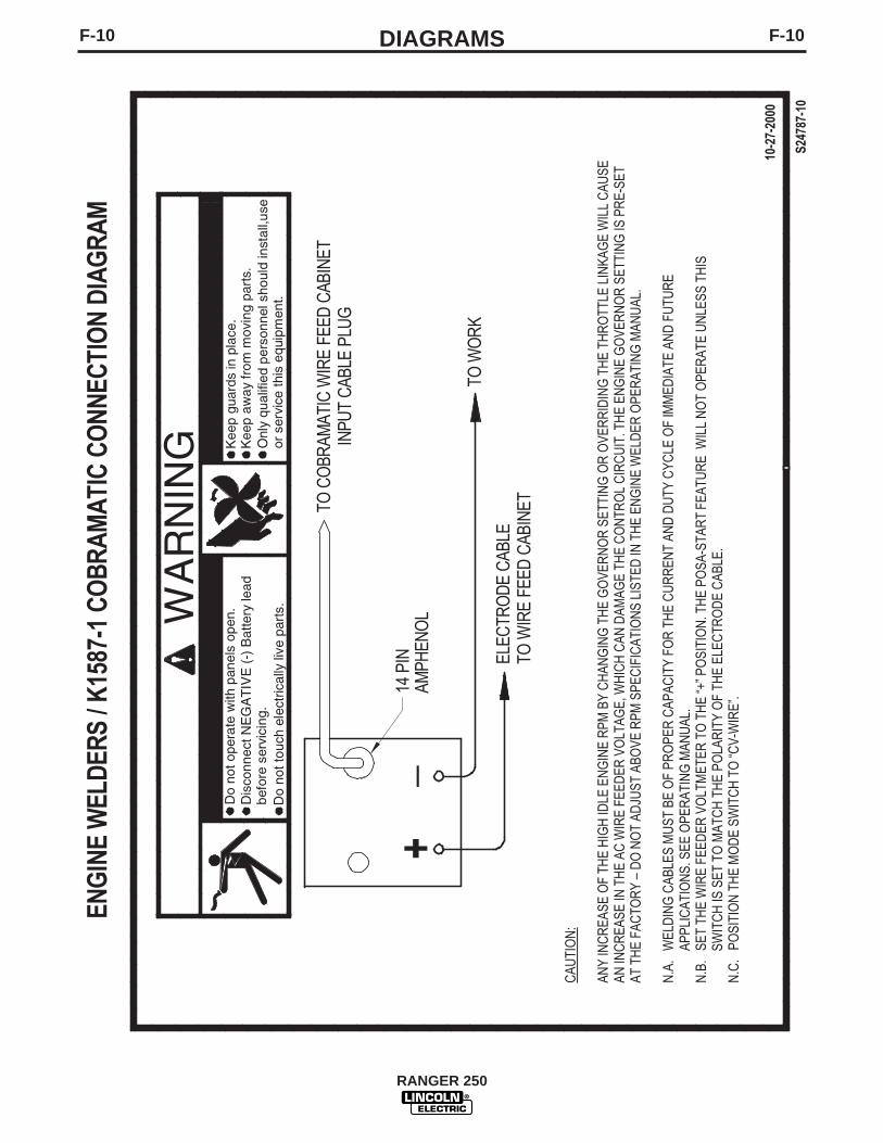
F-10DIAGRAMSF-10
RANGER 250

F-11DIAGRAMSF-11
RANGER 250

F-12DIAGRAMSF-12
RANGER 250
NO
TE
: T
his
dia
gra
m is
fo
r re
fere
nce
onl
y.
It m
ay n
ot
be
accu
rate
fo
r al
l mac
hine
s co
vere
d b
y th
is m
anua
l. T
he s
pec
ific
dia
gra
m f
or
a p
artic
ular
co
de
is p
aste
d in
sid
eth
e m
achi
ne o
n o
ne o
f th
e en
clo
sure
pan
els.
If
the
dia
gra
m is
ille
gib
le, w
rite
to
the
Ser
vice
Dep
artm
ent
for
a re
pla
cem
ent.
Giv
e th
e eq
uip
men
t co
de
num
ber
..

F-13DIAGRAMSF-13
RANGER 250
NO
TE
: T
his
dia
gra
m is
fo
r re
fere
nce
onl
y.
It m
ay n
ot
be
accu
rate
fo
r al
l mac
hine
s co
vere
d b
y th
is m
anua
l. T
he s
pec
ific
dia
gra
m f
or
a p
artic
ular
co
de
is p
aste
d in
sid
eth
e m
achi
ne o
n o
ne o
f th
e en
clo
sure
pan
els.
If
the
dia
gra
m is
ille
gib
le, w
rite
to
the
Ser
vice
Dep
artm
ent
for
a re
pla
cem
ent.
Giv
e th
e eq
uip
men
t co
de
num
ber
..
CONT
ACTO
RCO
NTRO
L
SHOW
N IN
"WEL
DING
ON"
POSI
TION
WIR
E F
EED
PO
WE
R
W
IND
ING
42 V
AC
C11
C10
42 V
AC
FIE
LD W
INDI
NG
GN
D. S
CR
EW O
N L
EFT
INS
IDE
CA
SE
FRO
NT
D3
ARC
CO
NTR
OL
10K
ALL
CAS
E FR
ON
T C
OM
PON
ENTS
SH
OW
N V
IEW
ED
FR
OM
RE
AR
.
42
W3
CB7
15A
S1
9
7
W1
STA
TOR
WE
LDW
IND
ING
S
W3
W2
75
R1
7677
278
CC
WOU
TPUT
CON
T. P
OT
S3
2
GN
D-G
GN
D-D
GND
-E
300
AM
PM
OD
ULE
SHU
NT
50M
V=4
00 A
MP
S
3
RO
TOR
5A
3D3A
5A
5B
5C
3
6
3E6F
BLACK
50A
50A20
A
20A
BLA
CK
WHITEWHITE
BLACK
BLA
CK
WH
ITE
BLA
CK
BLA
CK
SIL
VER
SIL
VER
STA
TOR
AU
X. W
IND
ING
CONN
ECTO
RS V
IEW
ED F
ROM
INSE
RTIO
N EN
DEL
ECTR
ICAL
SYM
BOLS
PER
E15
37
FRAM
E GN
D.
5C
3A36B 6
6B
CB1 CB2
CB5
CB6
6B
5B
J101
J102
J100
3E
6E
115/
230V
10K
97
41
206B
206A
200A
201
201A20
0B
32
3A
5C
+
HO
UR
MET
ER22
4B
5
5H
HE
ATS
INK
208
4
279
BOTT
OM
GN
D IN
SID
E C
ASE
FRO
NT
PCB
1
D1
- TH
REE
PH
ASE
BRID
GE
REC
TIFI
ERW
4
W5
W6
63
W10
21
P6-J
6
16
8 1
9
P3-J
3
9
1
16
PCB
2 W
ELD
CO
NTR
OL
PC
BO
ARD
Shun
t
Sens
e/Id
ler/
PWM
204S
206S
S6
MO
DE
SE
LE
CT
OR
SW
ITC
H
2A
13
5G
206S
204S
14
208A
208B
A
432
1
222
TIG
CC
PIP
E
CV
220
218
214
8
CC
WR
2
B7
B8
L1 C
HOKE
W9 W8
36
WRA
P TW
O TU
RNS
#3 &
#6 LE
ADS
IN D
IREC
TION
SHOW
N TH
ROUG
HTO
ROID 3
6
RA
NG
ER 2
50G
- W
IRIN
G D
IAG
RA
M F
OR
CO
DE
1095
4 (K
OH
LER
) 109
53 (O
NA
N P
220
OH
V)
IDLE
R CO
NTRO
L
SHOW
N IN
"AUT
O" P
OSIT
ION
S4
252
251
C3
800u
f15
0vdc
POSI
TIVE
BR
USH
CO
NNE
CTE
DTO
SLI
P R
ING
NEA
RES
TTO
TH
E LA
MIN
ATIO
N
WH
ITE
TER
M.
L2
L3
TWIS
TED
PA
IRW
6
12 V
OLT
BATT
ERY
-
GND
-H
ENG
INE
BLO
CK
+
W11
(LO
CAT
ED
BEL
OW
TER
MIN
AL
2)
S1R
UN
-STO
PS
WIT
CH
(SH
OW
N IN
RU
N P
OS
.)
127
61
1 2
L2, L
3: R
F CH
OKE
S
169
81
CB8
TOP
GND.
SC
REW
ON
INSI
DE
OF
CASE
FR
ON
T
LEA
D C
OLO
R C
OD
E:
B=B
LAC
K O
R G
RA
YR
=RED
OR
PIN
KW
=WH
ITE
G=G
RE
EN (W
/YE
LLO
W S
TRIP
E)
FRAM
E GN
D.
41A
42A15
A
206A
21
S5
VOLT
ME
TER
POLA
RIT
YS
WIT
CH
SHO
WN
INPO
SIT
IVE
(+)
POS
ITIO
N
G42
84
31 32 GND
-B
A B C D E F
77B
21 75B
GN
D-A
41A
42A
76B
115V
AC
CO
NTA
CTO
R
77B
76B
WO
RK
75B
RE
MO
TEC
ON
TRO
L
42V
AC
GR
OU
ND
AM
PH
ENO
L 1
REM
OTE
CO
NTA
CTO
R
GR
OU
ND
AM
PH
ENO
L 2
CO
NTR
OL
J A D CH BK E F GI
208C
206C
BY
PAS
SFI
LTE
RA
SS
EM
BLY
5N
GND
-B
4B 2B 2B 4B
208C
206C
206B
4A
77A
76A
75A
2A 4AB
atte
ry C
harg
eLi
ght
PL2
9
1
16
8
7
1
12
6
P7 -
J7O
utpu
t &A
rc C
ont.
Mod
eSe
lect
P2 -
J2En
gine
&B
atte
ryFu
nctio
n
P1 -
J1A
mph
enol
,M
odel
Sele
ct,
Hot
Sta
rt
C8
C9
2523
Twis
ted
Pai
r
B4
B5
B6
B1
B2
B3
W5
200
777675
277
279
278
277
214
218
220
222
215
252
251
77A
76A
75A
2 4
208B
260
261
1314 23
260
261
224B
5G21
0C 5K
5K
210B
200N
GND
-K
GND
-N
GND
-E
GND
-N
5K5
5N
GND
-GG
ND-D G
ND-C
GND
-C
GND
-B GND
-A
31
GND
-J
GND
-J
200N
R3
25
Key
Key
S2
STA
RT
BU
TTO
N
224
5H
210A
R4
301
302
FRAM
EG
ROU
ND
GND
-K
GND
. SC
REW
ON
FAN
BAF
FLE.
209
EN
GIN
E C
OM
PO
NE
NT
S
B-AC
ACB +
GROU
NDIN
G TH
IS C
IRCU
ITST
OPS
THE
ENGI
NE
IGNI
TION
MOD
ULE
STAR
TER
12
3
P51
J51
OIL
PRES
SURE
SWIT
CH
VW
HITE
R
FUE
LS
HU
TOFF
SO
LEN
OID
ENGI
NE T
ERM
INAL
BLO
CK4
224
210
REGU
LATO
R
FLY
WH
EE
L A
LTE
RN
ATO
R212A
STAR
TER
CR1
SOLE
NOID
RU
225
211A
221
229
211
228
225
229
228
212
210A
210
210B
211
211A
221 5J
5J
IDLE
SOLE
NO
ID
215
210C
A.03
W10
W7

CE
NT
ER
OF
GR
AV
ITY
WIT
H O
IL I
N
EN
GIN
E A
ND
EM
PT
Y F
UE
L T
AN
K
TR
UC
K/U
ND
ER
CA
RR
IAG
E M
OU
NT
ING
HO
LE
S
41
.20
17
.50
19
.50
42
.10
20
.80
"A
"
"
B"
29
.88
33
.62
36
.24
10
.28
10
.78
7.2
22
4.8
62
.6
F-14DIAGRAMSF-14
RANGER 250
DIM
ENSI
ON
PR
INT
R
AN
GER
250
ON
AN
P22
0OH
V 22
.25
15.2
5D
IMEN
SIO
N“A
”D
IMEN
SIO
N“B
”
KO
HLE
R C
H20
23
.50
15.5
0
8/00
M19
410

NOTES
RANGER 250

NOTES
RANGER 250

WARNING
AVISO DEPRECAUCION
ATTENTION
WARNUNG
ATENÇÃO
Spanish
French
German
Portuguese
Japanese
Chinese
Korean
Arabic
READ AND UNDERSTAND THE MANUFACTURER’S INSTRUCTION FOR THIS EQUIPMENT AND THE CONSUMABLES TO BEUSED AND FOLLOW YOUR EMPLOYER’S SAFETY PRACTICES.
SE RECOMIENDA LEER Y ENTENDER LAS INSTRUCCIONES DEL FABRICANTE PARA EL USO DE ESTE EQUIPO Y LOSCONSUMIBLES QUE VA A UTILIZAR, SIGA LAS MEDIDAS DE SEGURIDAD DE SU SUPERVISOR.
LISEZ ET COMPRENEZ LES INSTRUCTIONS DU FABRICANT EN CE QUI REGARDE CET EQUIPMENT ET LES PRODUITS AETRE EMPLOYES ET SUIVEZ LES PROCEDURES DE SECURITE DE VOTRE EMPLOYEUR.
LESEN SIE UND BEFOLGEN SIE DIE BETRIEBSANLEITUNG DER ANLAGE UND DEN ELEKTRODENEINSATZ DES HER-STELLERS. DIE UNFALLVERHÜTUNGSVORSCHRIFTEN DES ARBEITGEBERS SIND EBENFALLS ZU BEACHTEN.
● Do not touch electrically live parts orelectrode with skin or wet clothing.
● Insulate yourself from work andground.
● No toque las partes o los electrodosbajo carga con la piel o ropa moja-da.
● Aislese del trabajo y de la tierra.
● Ne laissez ni la peau ni des vête-ments mouillés entrer en contactavec des pièces sous tension.
● Isolez-vous du travail et de la terre.
● Berühren Sie keine stromführendenTeile oder Elektroden mit IhremKörper oder feuchter Kleidung!
● Isolieren Sie sich von denElektroden und dem Erdboden!
● Não toque partes elétricas e elec-trodos com a pele ou roupa molha-da.
● Isole-se da peça e terra.
● Keep flammable materials away.
● Mantenga el material combustiblefuera del área de trabajo.
● Gardez à l’écart de tout matérielinflammable.
● Entfernen Sie brennbarres Material!
● Mantenha inflamáveis bem guarda-dos.
● Wear eye, ear and body protection.
● Protéjase los ojos, los oídos y elcuerpo.
● Protégez vos yeux, vos oreilles etvotre corps.
● Tragen Sie Augen-, Ohren- und Kör-perschutz!
● Use proteção para a vista, ouvido ecorpo.

WARNING
AVISO DEPRECAUCION
ATTENTION
WARNUNG
ATENÇÃO
Spanish
French
German
Portuguese
Japanese
Chinese
Korean
Arabic
LEIA E COMPREENDA AS INSTRUÇÕES DO FABRICANTE PARA ESTE EQUIPAMENTO E AS PARTES DE USO, E SIGA ASPRÁTICAS DE SEGURANÇA DO EMPREGADOR.
● Keep your head out of fumes.● Use ventilation or exhaust to
remove fumes from breathing zone.
● Los humos fuera de la zona de res-piración.
● Mantenga la cabeza fuera de loshumos. Utilice ventilación oaspiración para gases.
● Gardez la tête à l’écart des fumées.● Utilisez un ventilateur ou un aspira-
teur pour ôter les fumées des zonesde travail.
● Vermeiden Sie das Einatmen vonSchweibrauch!
● Sorgen Sie für gute Be- undEntlüftung des Arbeitsplatzes!
● Mantenha seu rosto da fumaça.● Use ventilação e exhaustão para
remover fumo da zona respiratória.
● Turn power off before servicing.
● Desconectar el cable de ali-mentación de poder de la máquinaantes de iniciar cualquier servicio.
● Débranchez le courant avant l’entre-tien.
● Strom vor Wartungsarbeitenabschalten! (Netzstrom völlig öff-nen; Maschine anhalten!)
● Não opere com as tampas removidas.● Desligue a corrente antes de fazer
serviço.● Não toque as partes elétricas nuas.
● Do not operate with panel open orguards off.
● No operar con panel abierto oguardas quitadas.
● N’opérez pas avec les panneauxouverts ou avec les dispositifs deprotection enlevés.
● Anlage nie ohne Schutzgehäuseoder Innenschutzverkleidung inBetrieb setzen!
● Mantenha-se afastado das partesmoventes.
● Não opere com os paineis abertosou guardas removidas.

• Sales and Service through Subsidiaries and Distributors Worldwide •
Cleveland, Ohio 44117-1199 U.S.A. TEL: 216.481.8100 FAX: 216.486.1751 WEB SITE: www.lincolnelectric.com
• World's Leader in Welding and Cutting Products •