Embed Size (px)
Citation preview

RANGER 300 D and 300 DLX™
OPERATOR’S MANUAL
IM571-AFebruary, 2003
Safety Depends on YouLincoln arc welding and cuttingequipment is designed and builtwith safety in mind. However, youroverall safety can be increased byproper installation ... and thought-ful operation on your part. DONOT INSTALL, OPERATE ORREPAIR THIS EQUIPMENTWITHOUT READING THISMANUAL AND THE SAFETYPRECAUTIONS CONTAINEDTHROUGHOUT. And, mostimportantly, think before you actand be careful.
For use with machines having Code Numbers: 10399; 10400; 10850
• Sales and Service through Subsidiaries and Distributors Worldwide •
Cleveland, Ohio 44117-1199 U.S.A. TEL: 216.481.8100 FAX: 216.486.1751 WEB SITE: www.lincolnelectric.com
• World's Leader in Welding and Cutting Products •
Date of Purchase:Serial Number:Code Number:Model:Where Purchased:
Copyright © 2003 Lincoln Global Inc.
This manual covers equipment which is no longer in production by The Lincoln Electric Co. Speci�cations and availability of optional features may have changed.

FOR ENGINEpowered equipment.
1.a. Turn the engine off before troubleshooting and maintenancework unless the maintenance work requires it to be running.
____________________________________________________1.b. Operate engines in open, well-ventilated
areas or vent the engine exhaust fumes outdoors.
____________________________________________________1.c. Do not add the fuel near an open flame
welding arc or when the engine is running.Stop the engine and allow it to cool beforerefueling to prevent spilled fuel from vaporiz-ing on contact with hot engine parts andigniting. Do not spill fuel when filling tank. Iffuel is spilled, wipe it up and do not startengine until fumes have been eliminated.
____________________________________________________1.d. Keep all equipment safety guards, covers and devices in
position and in good repair.Keep hands, hair, clothing andtools away from V-belts, gears, fans and all other movingparts when starting, operating or repairing equipment.
____________________________________________________
1.e. In some cases it may be necessary to remove safetyguards to perform required maintenance. Removeguards only when necessary and replace them when themaintenance requiring their removal is complete.Always use the greatest care when working near movingparts.
___________________________________________________1.f. Do not put your hands near the engine fan.
Do not attempt to override the governor oridler by pushing on the throttle control rodswhile the engine is running.
___________________________________________________1.g. To prevent accidentally starting gasoline engines while
turning the engine or welding generator during maintenancework, disconnect the spark plug wires, distributor cap ormagneto wire as appropriate.
iSAFETYi
ARC WELDING CAN BE HAZARDOUS. PROTECT YOURSELF AND OTHERS FROM POSSIBLE SERIOUS INJURY OR DEATH.KEEP CHILDREN AWAY. PACEMAKER WEARERS SHOULD CONSULT WITH THEIR DOCTOR BEFORE OPERATING.
Read and understand the following safety highlights. For additional safety information, it is strongly recommended that youpurchase a copy of “Safety in Welding & Cutting - ANSI Standard Z49.1” from the American Welding Society, P.O. Box351040, Miami, Florida 33135 or CSA Standard W117.2-1974. A Free copy of “Arc Welding Safety” booklet E205 is availablefrom the Lincoln Electric Company, 22801 St. Clair Avenue, Cleveland, Ohio 44117-1199.
BE SURE THAT ALL INSTALLATION, OPERATION, MAINTENANCE AND REPAIR PROCEDURES AREPERFORMED ONLY BY QUALIFIED INDIVIDUALS.
WARNING
Mar ‘95
ELECTRIC AND MAGNETIC FIELDSmay be dangerous
2.a. Electric current flowing through any conductor causes localized Electric and Magnetic Fields (EMF). Welding current creates EMF fields around welding cables and welding machines
2.b. EMF fields may interfere with some pacemakers, andwelders having a pacemaker should consult their physicianbefore welding.
2.c. Exposure to EMF fields in welding may have other healtheffects which are now not known.
2.d. All welders should use the following procedures in order tominimize exposure to EMF fields from the welding circuit:
2.d.1. Route the electrode and work cables together - Securethem with tape when possible.
2.d.2. Never coil the electrode lead around your body.
2.d.3. Do not place your body between the electrode andwork cables. If the electrode cable is on your right side, the work cable should also be on your right side.
2.d.4. Connect the work cable to the workpiece as close aspossible to the area being welded.
2.d.5. Do not work next to welding power source.
1.h. To avoid scalding, do not remove theradiator pressure cap when the engine ishot.
CALIFORNIA PROPOSITION 65 WARNINGS
Diesel engine exhaust and some of its constituentsare known to the State of California to cause can-cer, birth defects, and other reproductive harm.
The engine exhaust from this product containschemicals known to the State of California to causecancer, birth defects, or other reproductive harm.
The Above For Diesel Engines The Above For Gasoline Engines

iiSAFETYii
ARC RAYS can burn.4.a. Use a shield with the proper filter and cover
plates to protect your eyes from sparks andthe rays of the arc when welding or observingopen arc welding. Headshield and filter lensshould conform to ANSI Z87. I standards.
4.b. Use suitable clothing made from durable flame-resistantmaterial to protect your skin and that of your helpers fromthe arc rays.
4.c. Protect other nearby personnel with suitable, non-flammablescreening and/or warn them not to watch the arc nor exposethemselves to the arc rays or to hot spatter or metal.
ELECTRIC SHOCK cankill.3.a. The electrode and work (or ground) circuits
are electrically “hot” when the welder is on.Do not touch these “hot” parts with your bareskin or wet clothing. Wear dry, hole-free
gloves to insulate hands.
3.b. Insulate yourself from work and ground using dry insulation.Make certain the insulation is large enough to cover your fullarea of physical contact with work and ground.
In addition to the normal safety precautions, if weldingmust be performed under electrically hazardousconditions (in damp locations or while wearing wetclothing; on metal structures such as floors, gratings orscaffolds; when in cramped positions such as sitting,kneeling or lying, if there is a high risk of unavoidable oraccidental contact with the workpiece or ground) usethe following equipment:
• Semiautomatic DC Constant Voltage (Wire) Welder.• DC Manual (Stick) Welder.• AC Welder with Reduced Voltage Control.
3.c. In semiautomatic or automatic wire welding, the electrode,electrode reel, welding head, nozzle or semiautomaticwelding gun are also electrically “hot”.
3.d. Always be sure the work cable makes a good electricalconnection with the metal being welded. The connectionshould be as close as possible to the area being welded.
3.e. Ground the work or metal to be welded to a good electrical(earth) ground.
3.f. Maintain the electrode holder, work clamp, welding cable andwelding machine in good, safe operating condition. Replacedamaged insulation.
3.g. Never dip the electrode in water for cooling.
3.h. Never simultaneously touch electrically “hot” parts ofelectrode holders connected to two welders because voltagebetween the two can be the total of the open circuit voltageof both welders.
3.i. When working above floor level, use a safety belt to protectyourself from a fall should you get a shock.
3.j. Also see Items 6.c. and 8.
FUMES AND GASEScan be dangerous.5.a. Welding may produce fumes and gases
hazardous to health. Avoid breathing thesefumes and gases.When welding, keepyour head out of the fume. Use enoughventilation and/or exhaust at the arc to keep
fumes and gases away from the breathing zone. Whenwelding with electrodes which require specialventilation such as stainless or hard facing (seeinstructions on container or MSDS) or on lead orcadmium plated steel and other metals or coatingswhich produce highly toxic fumes, keep exposure aslow as possible and below Threshold Limit Values (TLV)using local exhaust or mechanical ventilation. Inconfined spaces or in some circumstances, outdoors, arespirator may be required. Additional precautions arealso required when welding on galvanized steel.
5.b. Do not weld in locations near chlorinated hydrocarbon vaporscoming from degreasing, cleaning or spraying operations.The heat and rays of the arc can react with solvent vapors toform phosgene, a highly toxic gas, and other irritating prod-ucts.
5.c. Shielding gases used for arc welding can displace air andcause injury or death. Always use enough ventilation,especially in confined areas, to insure breathing air is safe.
5.d. Read and understand the manufacturer’s instructions for thisequipment and the consumables to be used, including thematerial safety data sheet (MSDS) and follow youremployer’s safety practices. MSDS forms are available fromyour welding distributor or from the manufacturer.
5.e. Also see item 1.b.
Mar ‘95

FOR ELECTRICALLYpowered equipment.
8.a. Turn off input power using the disconnectswitch at the fuse box before working onthe equipment.
8.b. Install equipment in accordance with the U.S. NationalElectrical Code, all local codes and the manufacturer’srecommendations.
8.c. Ground the equipment in accordance with the U.S. NationalElectrical Code and the manufacturer’s recommendations.
CYLINDER may explodeif damaged.7.a. Use only compressed gas cylinders
containing the correct shielding gas for theprocess used and properly operatingregulators designed for the gas and
pressure used. All hoses, fittings, etc. should be suitable forthe application and maintained in good condition.
7.b. Always keep cylinders in an upright position securelychained to an undercarriage or fixed support.
7.c. Cylinders should be located:• Away from areas where they may be struck or subjected tophysical damage.
• A safe distance from arc welding or cutting operations andany other source of heat, sparks, or flame.
7.d. Never allow the electrode, electrode holder or any otherelectrically “hot” parts to touch a cylinder.
7.e. Keep your head and face away from the cylinder valve outletwhen opening the cylinder valve.
7.f. Valve protection caps should always be in place and handtight except when the cylinder is in use or connected foruse.
7.g. Read and follow the instructions on compressed gascylinders, associated equipment, and CGA publication P-l,“Precautions for Safe Handling of Compressed Gases inCylinders,” available from the Compressed Gas Association1235 Jefferson Davis Highway, Arlington, VA 22202.
iiiSAFETYiii
Mar ‘95
WELDING SPARKS cancause fire or explosion.6.a. Remove fire hazards from the welding area.
If this is not possible, cover them to preventthe welding sparks from starting a fire.Remember that welding sparks and hot
materials from welding can easily go through small cracksand openings to adjacent areas. Avoid welding nearhydraulic lines. Have a fire extinguisher readily available.
6.b. Where compressed gases are to be used at the job site,special precautions should be used to prevent hazardoussituations. Refer to “Safety in Welding and Cutting” (ANSIStandard Z49.1) and the operating information for theequipment being used.
6.c. When not welding, make certain no part of the electrodecircuit is touching the work or ground. Accidental contactcan cause overheating and create a fire hazard.
6.d. Do not heat, cut or weld tanks, drums or containers until theproper steps have been taken to insure that such procedureswill not cause flammable or toxic vapors from substancesinside. They can cause an explosion even though they havebeen “cleaned”. For information, purchase “RecommendedSafe Practices for the Preparation for Welding and Cutting ofContainers and Piping That Have Held HazardousSubstances”, AWS F4.1 from the American Welding Society(see address above).
6.e. Vent hollow castings or containers before heating, cutting orwelding. They may explode.
6.f. Sparks and spatter are thrown from the welding arc. Wear oilfree protective garments such as leather gloves, heavy shirt,cuffless trousers, high shoes and a cap over your hair. Wearear plugs when welding out of position or in confined places.Always wear safety glasses with side shields when in awelding area.
6.g. Connect the work cable to the work as close to the weldingarea as practical. Work cables connected to the buildingframework or other locations away from the welding areaincrease the possibility of the welding current passingthrough lifting chains, crane cables or other alternate cir-cuits. This can create fire hazards or overheat lifting chainsor cables until they fail.
6.h. Also see item 1.c.

ivSAFETYiv

Thank You for selecting a QUALITY product by Lincoln Electric. We want youto take pride in operating this Lincoln Electric Company product••• as much pride as we have in bringing this product to you!
Read this Operators Manual completely before attempting to use this equipment. Save this manual and keep ithandy for quick reference. Pay particular attention to the safety instructions we have provided for your protection.The level of seriousness to be applied to each is explained below:
WARNINGThis statement appears where the information must be followed exactly to avoid serious personal injury orloss of life.
This statement appears where the information must be followed to avoid minor personal injury or damage tothis equipment.
CAUTION
Please Examine Carton and Equipment For Damage ImmediatelyWhen this equipment is shipped, title passes to the purchaser upon receipt by the carrier. Consequently, Claimsfor material damaged in shipment must be made by the purchaser against the transportation company at thetime the shipment is received.
Please record your equipment identification information below for future reference. This information can befound on your machine nameplate.
Model Name & Number _____________________________________
Code & Serial Number _____________________________________
Date of Purchase _____________________________________
Whenever you request replacement parts for or information on this equipment always supply the informationyou have recorded above.
vv

viTABLE OF CONTENTSPage
Installation.......................................................................................................................Section ATechnical Specifications.......................................................................................................A-1Installation Instructions. ........................................................................................................A-2
Location and Ventilation................................................................................................A-2Storing...........................................................................................................................A-2Stacking ........................................................................................................................A-2Tilting.............................................................................................................................A-2High Altitude Operation .................................................................................................A-3Lifting.............................................................................................................................A-3Additional Safety Precautions .......................................................................................A-3
Pre-Operation Engine Service..............................................................................................A-3Oil ..................................................................................................................................A-3Fuel ...............................................................................................................................A-4Engine Coolant..............................................................................................................A-4Battery Connections......................................................................................................A-4Exhaust Deflector ..........................................................................................................A-4Spark Arrester ...............................................................................................................A-4
Electrical Connections..........................................................................................................A-5Machine Grounding.......................................................................................................A-5Welding Cable Connections..........................................................................................A-5
Auxiliary Power Receptacles, Plugs, and Hand-Held Equipment ........................................A-6Circuit Breakers....................................................................................................................A-6Premises Wiring ...................................................................................................................A-6
Operation.........................................................................................................................Section BGeneral Description..............................................................................................................B-1Design Features ...................................................................................................................B-1Additional Features ..............................................................................................................B-2Recommended Applications.................................................................................................B-2Limitations ............................................................................................................................B-2Additional Safety Precautions .............................................................................................B-2
Controls and Settings ..................................................................................................................B-2Welder / Generator Controls .........................................................................................B-3Engine Controls.............................................................................................................B-4
Engine Operation .................................................................................................................B-5Before Starting the Engine ............................................................................................B-5Starting the Engine........................................................................................................B-6Cold Weather Starting and Operation ...........................................................................B-6Stoping the Engine........................................................................................................B-6Break-In Period .............................................................................................................B-7
Welding Operation................................................................................................................B-7AC / DC Stick (Constant Current) Welding ...................................................................B-8AC / DC TIG (Constant Current) Welding .....................................................................B-9DC Wire Feed Welding (CV) with Ranger 300 DLX......................................................B-9DC Wire Feed Welding (CV) with Ranger 300 D ........................................................B-10Carbon Arc Gouging (Constant Current).....................................................................B-10Summary of Welding Processes and Machine Settings .............................................B-11
Auxiliary Power...................................................................................................................B-13Simultaneous Welding and Power Loads ...................................................................B-13120 / 240 Volt Dual Voltage Receptacle .....................................................................B-14120 V Duplex Receptacles..........................................................................................B-14
Accessories .....................................................................................................Section CGeneral Options / Accessories ..............................................................................C-1TIG Welding Options / Accessories.......................................................................C-1Semiautomatic FCAW and MIG Welding (Ranger 300 DLX) Options / Accessories ..........C-1Semiautomatic FCAW and MIG Welding (Ranger 300 D) Options / Accessories...............C-2

vii TABLE OF CONTENTSPage
Maintenance ....................................................................................................Section DSafety Precautions ................................................................................................D-1Kubota Engine Maintenance Schedule .................................................................D-1Kubota Engine Maintenance Components ............................................................D-1Routine and Periodic Engine Maintenance ...........................................................D-2
Oil....................................................................................................................D-2Oil Filter...........................................................................................................D-2Fuel .................................................................................................................D-3Bleeding The Fuel System..............................................................................D-3Air Filter...........................................................................................................D-3Tightening the Fan Belt ...................................................................................D-3Cooling System...............................................................................................D-3Battery Maintenance .......................................................................................D-4
Welder / Generator Maintenance ..........................................................................D-5Storage ...........................................................................................................D-5Cleaning..........................................................................................................D-5Brush Removal and Replacement ..................................................................D-5
Troubleshooting ..............................................................................................Section ESafety Precautions.................................................................................................E-1How to Use Troubleshooting Guide.......................................................................E-1Troubleshooting Guide.............................................................................E-2 thru E-4
Connection Diagrams, Wiring Diagrams & Dimension Print.......................Section F
Parts List .....................................................................................................P-290 Series

A-1INSTALLATION
RANGER 300 D AND 300 DLX
A-1
TECHNICAL SPECIFICATIONS - Ranger 300 D (K1522-1), Ranger 300 DLX (K1522-2)
Make/Model Description Speed (RPM) Displacement Starting CapacitiesSystem
Kubota 3 cylinder High Idle 3700 54.9 cu. in 12VDC battery Fuel: 10 gal.DH905 26.0 HP @ Low Idle 2150 (898 cc) (Group 45, 495 38 LDiesel Engine 3600 RPM Full Load 3600 cold crank amps)
Bore x Stroke 1 KW Starter Oil: 5.4 Qts.30 A. Alternator 5.1 L
2.83” x 2.90” w/ built in reg.(72 mm x 73.6mm) Coolant: 5.7 qts.
5.4 L
INPUT - DIESEL ENGINE
RATED OUTPUT - WELDER
HEIGHT WIDTH DEPTH WEIGHT
37.38 in. 24.75 in. 60.50 in. 1093 lbs. (300 D)1133 lbs. (300 DLX)
949.4 mm 628.7 mm 1528.6 mm 480.8 kg. (300 D)499.0 kg. (300 DLX)
OUTPUT - GENERATOR
Welding Output Volts at Rated Amps Duty Cycle Max. OCV @ 3700 RPM
DC Constant Current 300 amps 25 volts 100%AC Constant Current 300 amps 25 volts 100%
80 volts RMSDC Constant Voltage (300 D) 200 amps 20 volts 100%
DC Constant Voltage (300 DLX) 300 amps 30 volts 60%*DC Constant Voltage (300 DLX) 280 amps 30 volts 100%
Auxiliary Power 1
12,000 Watts, 60 Hz120/240 Volts
100 % Duty Cycle
PHYSICAL DIMENSIONS
1. Output rating in watts is equivalent to volt-amperes at unity power factor. Output voltage is within ± 10% at all loads up torated capacity. When welding, available auxiliary power will be reduced.
* Duty cycle is based on a 10 minute period. The machine can be loaded to 300 amps for 6 minutes out of every 10 minuteperiod.

A-2INSTALLATION
RANGER 300 D AND 300 DLX
A-2
SAFETY PRECAUTIONS
Only qualified personnel should install,use, or service this equipment.
LOCATION AND VENTILATION
Whenever you use the RANGER 300, be sure thatclean cooling air can flow through the machine’sdiesel engine and the machine case. Avoid dusty,dirty areas. Also, keep the machine away from heatsources. Do not place the engine end of the machineanywhere near hot engine exhaust from anothermachine or closer than two feet from a wall. And ofcourse, make sure that engine exhaust is ventilated toan open, outside area.
The RANGER 300 may be used outdoors. Do not setthe machine in puddles or otherwise submerge it inwater. Such practices pose safety hazards and causeimproper operation and corrosion of parts.
Always operate the RANGER 300 with the case roofon and all machine components completely assem-bled. This will protect you from the dangers of movingparts, hot metal surfaces, and live electrical devices.
Do not attempt to use this equipment until youhave thoroughly read the engine manufacturer’smanual supplied with your welder. It includesimportant safety precautions, detailed enginestarting, operating and maintenance instructions,and parts lists.------------------------------------------------------------------------
ELECTRIC SHOCK can kill.• Do not touch electrically live parts orelectrode with skin or wet clothing.• Insulate yourself from work andground• Always wear dry insulating gloves.
------------------------------------------------------------------------ENGINE EXHAUST can kill.• Use in open, well ventilated areas orvent exhaust outside.
------------------------------------------------------------------------MOVING PARTS can injure.• Do not operate with doors open orguards off.• Stop engine before servicing.• Keep away from moving parts.
------------------------------------------------------------------------
See additional warning information atfront of this operator’s manual.
-----------------------------------------------------------
WARNING
STORING
1. Store the machine in a cool, dry place when it is notin use. Protect it from dust and dirt. Keep it whereit can’t be accidentally damaged from constructionactivities, moving vehicles, and other hazards.
2. Drain the engine oil and refill with fresh 10W30 oil.Run the engine for about five minutes to circulateoil to all the parts. See the MAINTENANCE sectionof this manual for details on changing oil.
3. If you are storing the machine for more than 30days, drain the coolant from the radiator. Open thecock at the bottom of the radiator and remove thepressure cap so that the coolant drains completely.Attach a note that says “NO WATER” on the radia-tor.
4. Remove the battery, recharge it, and adjust theelectrolyte level. Store the battery in a dry, darkplace.
5. If the engine is not used for a long period of time,every two to three months fill the radiator and runthe engine for about five minutes to keep it freefrom rust.
STACKING
RANGER 300 machines CANNOT be stacked.
TILTING
Place the machine on a secure, level surface whenev-er you use it or store it. Any surfaces you place it onother than the ground must be firm, non-skid, andstructurally sound.
The diesel engine is designed to run in a level positionfor best performance. It can operate at an angle, butthis should never be more than 20 degrees in anydirection. If you do operate it at a slight angle, be sureto check the oil regularly and keep the oil level at theFULL mark as it would be in its normal level condition.Also, fuel capacity will be a little less at an angle.
DO NOT MOUNT OVER COMBUSTIBLE SUR-FACES.Where there is a combustible surface directly understationary or fixed electrical equipment, the surfaceshall be covered with a steel plate at least.06”(1.6mm) thick, which shall extend not more than5.90”(150mm) beyond the equipment on all sides.
CAUTION

A-3INSTALLATION
RANGER 300 D AND 300 DLX
A-3
HIGH ALTITUDE OPERATION
It may be necessary to de-rate the welder output athigher altitudes. Derate the welder output 0.4% forevery 100 ft. (30 m) above 500 ft. (150 m). Someengine adjustment may be required above 5,000 ft.(1,500 m). Contact a Kubota Service Representative.
LIFTING
The RANGER 300 weighs approximately 1150lbs/522 kg. A lift bail is mounted to the machine frameand should always be used when lifting the machine.
ADDITIONAL SAFETY PRECAUTIONS
FALLING EQUIPMENT can causeinjury.
● Do not lift this machine using liftbale if it is equipped with a heavyaccessory such as trailer or gascylinder.
● Lift only with equipment of adequate liftingcapacity.
● Be sure machine is stable when lifting.
The recommended undercarriage for use with thisequipment for in-plant and yard towing by a vehicle isLincoln’s K953-1. If the user adapts a non-Lincolnundercarriage, he must assume responsibility that themethod of attachment and usage does not result in asafety hazard nor damage the welding equipment.Some of the factors to be considered are as follows:
1. Design capacity of undercarriage vs. weight ofLincoln equipment and likely additional attach-ments.
2. Proper support of, and attachment to, the base ofthe welding equipment so there will be no unduestress to the framework.
3. Proper placement of the equipment on the under-carriage to insure stability side to side and front toback when being moved and when standing byitself while being operated or serviced.
WARNING
4. Typical conditions of use, i.e., travel speed; rough-ness of surface on which the undercarriage will beoperated; environmental conditions; likely mainte-nance.
5. Conformance with federal, state and local laws.(1)
(1) Consult applicable federal, state and local laws regardingspecific requirements for use on public highways.
PRE-OPERATION ENGINE SERVICE
READ and UNDERSTAND the engine operating andmaintenance instructions supplied with this machine.
------------------------------------------------------------------------
• Keep hands way from the engine muffler or HOTengine parts.
• Stop the engine when fueling.
• Do not smoke when fueling.
• Do not overfill the fuel tank.
• Wipe up spilled fuel and allow the fumes to clearbefore starting the engine.
• Keep sparks and flame away from the fuel tank.------------------------------------------------------------------------
OIL
The RANGER 300 is shipped with the engine filledwith SAE 10W-30 oil. CHECK THE OIL LEVELBEFORE YOU START THE ENGINE. If it is not full,add enough oil to fill it to the full mark.
Always use oil that is rated for diesel engine service(API classification of CD/CE).
For more information on oil viscosity and service con-ditions, see the MAINTENANCE section of this manu-al and the engine Operator’s Manual.
WARNING
CAUTION

A-4INSTALLATION
RANGER 300 D AND 300 DLX
A-4
FUEL
Fill the fuel tank with clean No. 2, diesel fuel only. Donot fill to the top of the filler neck to allow room forexpansion.
The RANGER 300 has a 10 gallon (38 liter) fuel tankwith a top fill and fuel gauge mounted on the controlpanel. See the OPERATION and MAINTENANCEsections of this manual for more details about fuel.
ENGINE COOLANT
HOT COOLANT can burn skin.
• Do not remove cap if radiator is hot.
------------------------------------------------------------------------The welder is shipped with the engine and radiatorfilled with a 50% mixture of ethylene glycol and water.The recovery bottle should be partially filled. See theMAINTENANCE section and the engine Operator’sManual for more information on coolant.
BATTERY CONNECTIONS
GASES FROM BATTERY can explode.
● Keep sparks, flame and cigarettesaway from battery.
To prevent EXPLOSION when:
● INSTALLING A NEW BATTERY — disconnectnegative cable from old battery first and connectto new battery last.
● CONNECTING A BATTERY CHARGER —remove battery from welder by disconnecting nega-tive cable first, then positive cable and batteryclamp. When reinstalling, connectnegative cable last. Keep well ventilated.
● USING A BOOSTER — connect positive lead tobattery first then connect negative lead to negativebattery lead at engine foot.
● BATTERY ACID can burn eyes andskin.
● Wear gloves and eye protection andbe careful when working near battery.
● Follow instructions printed on battery.
------------------------------------------------------------------------
WARNING
WARNING
IMPORTANT: To prevent ELECTRICAL DAMAGEWHEN:
a) Installing new batteries.
b) Using a booster.
Use correct polarity — Negative Ground.
The RANGER 300 is shipped with the negative bat-tery cable disconnected. Before you operate themachine, make sure the Engine Switch is in the OFFposition and attach the disconnected cable securely tothe negative (-) battery terminal.
Remove the insulating cap from the negative batteryterminal. Replace and tighten negative battery cableterminal. NOTE: This machine is furnished with a wetcharged battery; if unused for several months, the bat-tery may require a booster charge. Be sure to use thecorrect polarity when charging the battery.
EXHAUST DEFLECTOR
Shut off the machine and allow the muffler to coolbefore touching the muffler.------------------------------------------------------------------------
The RANGER 300 is shipped with the exhaust deflec-tor detached. Install it on the muffler outlet using theclamp supplied. Rotate the deflector to the desireddirection before tightening the clamp.
SPARK ARRESTER
Diesel engine mufflers may emit sparks when theengine is running. Some federal, state, or local lawsrequire spark arresters in locations where unarrestedsparks could present a fire hazard.
Standard muffler and deflectors (like the ones includ-ed with the RANGER 300 do not act as sparkarresters. When local laws require it, a spark arrestermust be installed on the machine and properly main-tained. An optional spark arrester kit (K903-1) isavailable for your RANGER 300. See theACCESSORIES section of this manual for more infor-mation.
An incorrect spark arrester may lead to damage to theengine or reduce performance.------------------------------------------------------------------------
CAUTION
CAUTION

A-5INSTALLATION
RANGER 300 D AND 300 DLX
A-5
ELECTRICAL CONNECTIONS
See Figure B.1 in the OPERATION section of thismanual for location of the 115 and 230 volt recepta-cles, weld output terminals, circuit breakers andground stud.
MACHINE GROUNDING
Because the RANGER 300 creates its own powerfrom its diesel-engine driven generator, and if themachine is not connected to premises wiring (home,shop, etc.), you do not need to connect the machineframe to an earth ground. However, for best protec-tion against electrical shock, connect a heavy gaugewire (#8 AWG or larger) from the ground stud locatedon the bottom of the output panel (See Figure B.1) toa suitable earth ground such as a metal pipe driveninto the ground.
Do not ground the machine to a pipe that carriesexplosive or combustible material.------------------------------------------------------------------------
When the Ranger 300 is mounted on a truck or a trail-er, the machine generator ground stud MUST besecurely connected to the metal frame of the vehicle.See Figure B.1. The ground stud is marked with theground symbol.
If the RANGER 300 is connected to premises wiringsuch as a home or shop, it must be properly connect-ed to the system earth ground.
WELDING CABLE CONNECTIONS
CABLE SIZE AND LENGTH
Be sure to use welding cables that are large enough.The correct size and length becomes especiallyimportant when you are welding at a distance from thewelder.
Table A.1 lists recommended cable sizes and lengthsfor rated current and duty cycle. Length refers to thedistance from the welder to the work and back to thewelder. Cable diameters are increased for long cablelengths to reduce voltage drops.
Lincoln Electric offers a welding accessory kit with theproperly specif ied welding cables. See theACCESSORIES section of this manual for more infor-mation.
WARNING
Table A.1
CABLE INSTALLATION
Install the welding cables to your RANGER 300 as fol-lows. See Figure B.1 for location of parts.
1. The diesel engine must be OFF to install weldingcables.
2. Remove the flanged nuts from the output terminals.
3. Connect the electrode holder and work cables tothe weld output terminals. The terminals are identi-fied on the case front.
4. Tighten the flanged nuts securely.
5. Be certain that the metal piece you are welding (the“work”) is properly connected to the work clamp andcable.
6. Check and tighten the connections periodically.
• Loose connections will cause the output terminals tooverheat. The terminals may eventually melt.
• Do not cross the welding cables at the output termi-nal connection. Keep the cables isolated and sepa-rate from one another.
------------------------------------------------------------------------
TOTAL COMBINED LENGTH OFELECTRODE AND WORK CABLES
Cable Length
0-50 Ft. (0-15 meters)
50-100 Ft. (15-39 meters)
100-150 Ft. (30-46 meters)
150-200 Ft. (46-61 meters)
200-250 Ft. (61-76 meters)
Cable Size for 300 Amps
100% Duty Cycle1/0 AWG
1/0 AWG
2/0 AWG
2/0 AWG
3/0 AWG
CAUTION
A-6INSTALLATION
RANGER 300 D AND 300 DLX
A-6
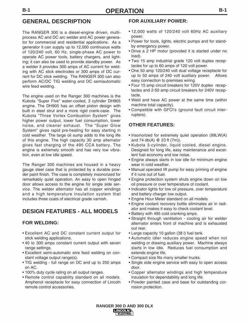
AUXILIARY POWER RECEPTACLES,PLUGS, AND HAND-HELD EQUIPMENT
The control panel of the RANGER 300 features threeauxiliary power receptacles: See Figure B.1.
• Two 15 amp, 120 volt duplex (double outlet) recepta-cles.
• One 50 amp 120/240 volt simplex (single outlet)receptacle.
Through these receptacles the machine can supply upto 12,000 rated continuous watts of single-phase, 60Hz AC power.
For further protection against electric shock, any elec-trical equipment connected to the generator recepta-cles must use a three-blade, grounded type plug or anUnderwriter’s Laboratories (UL) approved doubleinsulation system with a two-blade plug. Lincolnoffers an accessory plug kit that has the right type ofplugs. See the ACCESSORIES section of this manualfor more information.
If you need ground fault protection for hand-heldequipment refer to the K896-1 GFCI Receptacle kit inthe ACCESSORIES section of this manual for moreinformation.
CIRCUIT BREAKERS
The RANGER 300 machines are equipped with 50amp circuit breakers on the 120/240 V receptacle and15 amp circuit breakers on the 120 receptacles foroverload protection. Under high heat a breaker maytend to trip at lower loads than it would normally.
Never bypass the circuit breakers. Without overloadprotection, the RANGER 300 D/DLX could overheatand/or cause damage to the equipment being used.------------------------------------------------------------------------
CAUTION
PREMISES WIRING
The RANGER 300 is suitable for temporary, standby,or emergency power using the engine manufacturer’srecommended maintenance schedule. With its three-wire grounded neutral generator, it can be permanent-ly installed as a standby power unit for 240 volt, threewire, single phase 50 ampere service.
Only a licensed, certified, trained electrician shouldinstall the machine to a premises or residential elec-trical system. Be certain that:
• The installation complies with the National ElectricalCode and all other applicable electrical codes.
• The premises is isolated and no feedbacking intothe utility system can occur. Certain state and locallaws require the premises to be isolated before thegenerator is linked to the premises. Check yourstate and local requirements.
• A double pole, double throw transfer switch in con-junction with the properly rated double throw circuitbreaker is connected between the generator powerand the utility meter.
------------------------------------------------------------------------The following information and the connection diagram,Figure A.1, can be used as a guide by the electricianfor most applications to premises wiring.
1. Install a double pole, double throw switch betweenthe power company meter and the premises dis-connect. The switch rating must be the same as orgreater than the premises disconnect and serviceovercurrent protection.
2. Take the necessary steps to assure that the load islimited to the capacity of the RANGER 300 byinstalling a 50 amp 240 volt double pole circuitbreaker. Maximum rated load for the 240 volt auxil-iary is 50 amperes. Loading above 50 amperes willreduce output voltage below the allowable -10% ofrated voltage. This may damage appliances orother motor-driven equipment.
3. Install a 50 amp 120/240 volt plug (NEMA type 14-50) to a double pole circuit breaker using No. 8 orlarger, 4 conductor cable of the desired length.(The 50 amp 120/240 volt plug is available in theoptional power plug kit.
4. Plug this cable in to the 50 amp 120/240 volt recep-tacle on the RANGER 300 case front.
WARNING

A-7INSTALLATION
RANGER 300 D AND 300 DLX
A-7
Connection of Ranger 300 to premises wiringmust be done by a licensed electrician and mustcomply with the National Electrical Code and allother applicable electrical codes.
240 Volt60 Hz.3-WireService
POWER
COMPANY
METER
240 VOLT
120 VOLT
120 VOLT
LOADN
NEUTRALBUS
GROUND
PREMISESDISCONNECT AND
SERVICEOVERCURRENT
PROTECTION
GND
N
NOTE: No. 6 COPPER CONDUCTOR CABLE SEENATIONAL ELECTRICAL CODE FOR ALTERNATE WIRE
SIZE RECOMMENDATIONS.
240 VOLT
GROUNDED CONDUCTOR
50AMP240 VOLT
DOUBLEPOLE
CIRCUITBREAKER
DOUBLE POLE DOUBLE THROWSWITCH RATING TO BE THE SAMEAS OR GREATER THAN PREMISESSERVICE OVERCURRENTPROTECTION.
50 AMP, 120/240VOLT PLUG
NEMA TYPE 14-50
50 AMP, 120/240 VOLTRECEPTACLE
Figure A.1
CONNECTION OF RANGER 300 TO PREMISES WIRING
WARNING
B-1OPERATION
RANGER 300 D AND 300 DLX
B-1
GENERAL DESCRIPTION
The RANGER 300 is a diesel-engine driven, multi-process AC and DC arc welder and AC power genera-tor for commercial and residential applications. As agenerator it can supply up to 12,000 continuous wattsof 120/240 volt, 60 Hz, single-phase AC power tooperate AC power tools, battery chargers, and light-ing; it can also be used to provide standby power. Asa welder it provides 300 amps of AC current for weld-ing with AC stick electrodes or 300 amps of DC cur-rent for DC stick welding. The RANGER 300 can alsoperform AC/DC TIG welding and DC semiautomaticwire feed welding.
The engine used on the Ranger 300 machines is theKubota "Super Five" water-cooled, 3 cylinder DH905engine. The DH905 has an offset piston design withbuilt in steel strut and a more rigid crank-case. TheKubota "Three Vortex Combustion System" giveshigher power output, lower fuel consumption, lowernoise, and cleaner exhaust. The "Super GlowSystem" gives rapid pre-heating for easy starting incold weather. The large oil sump adds to the long lifeof this engine. The high capacity 30 amp alternatorgives fast charging of the 495 CCA battery. Theengine is extremely smooth and has very low vibra-tion, even at low idle speed.
The Ranger 300 machines are housed in a heavygauge steel case that is protected by a durable pow-der paint finish. The case is completely insonorized forremarkably quiet operation. An easy to open hingeddoor allows access to the engine for single side ser-vice. The welder alternator has all copper windingsand a high temperature insulation system thatincludes three coats of electrical grade varnish.
DESIGN FEATURES - ALL MODELS
FOR WELDING:
• Excellent AC and DC constant current output forstick welding applications.
• 40 to 300 amps constant current output with sevenrange settings.
• Excellent semi-automatic wire feed welding on con-stant voltage output range(s).
• TIG welding - full range on DC and up to 250 ampson AC.
• 100% duty cycle rating on all output ranges.• Remote control capability standard on all models.
Amphenol receptacle for easy connection of Lincolnremote control accessories.
FOR AUXILIARY POWER:
• 12,000 watts of 120/240 volt 60Hz AC auxiliarypower.
• Power for tools, lights, electric pumps and for stand-by emergency power.
• Drive a 2 HP motor (provided it is started under noload).
• Two 15 amp industrial grade 120 volt duplex recep-tacles for up to 60 amps of 120 volt power.
• One 50 amp 120/240 volt dual voltage receptacle forup to 50 amps of 240 volt auxiliary power. Allowseasy connection to premises wiring.
• Four 15 amp circuit breakers for 120V duplex recep-tacles and 2-50 amp circuit breakers for 240V recep-tacle.
• Weld and have AC power at the same time (withinmachine total capacity).
• Compatible with GFCI's (ground fault circuit inter-rupters).
OTHER FEATURES:
• Insonorized for extremely quiet operation (99LW(A)and 74 db(A) @ 23 ft (7m)).
• Kubota 3-cylinder, liquid cooled, diesel engine.Designed for long life, easy maintenance and excel-lent fuel economy and low noise.
• Engine always starts in low idle for minimum enginewear in cold weather.
• Manual operated lift pump for easy priming of engineif it runs out of fuel.
• Engine protection system shuts engine down on lowoil pressure or over temperature of coolant.
• Indicator lights for low oil pressure, over temperatureand battery charger low output.
• Engine Hour Meter standard on all models.• Engine coolant recovery bottle eliminates air in radi-
ator and makes it easy to check coolant level.• Battery with 495 cold cranking amps.• Straight through ventilation - cooling air for welder
alternator enters front of machine and is exhaustedout rear.
• Large capacity 10 gallon (38 l) fuel tank.• Automatic idler reduces engine speed when not
welding or drawing auxiliary power. Machine alwaysstarts in low idle. Reduces fuel consumption andextends engine life.
• Compact size fits many smaller trucks.• Single side engine service with easy to open access
door.• Copper alternator windings and high temperature
insulation for dependability and long life.• Powder painted case and base for outstanding cor-
rosion protection.

B-2OPERATIONB-2
ADDITIONAL FEATURES RANGER 300 D (K1522-1):
• One constant voltage wire-feed welding range - 80 to200 amps.The wire feed setting permits the Ranger 300D to beused with the LN-25 Wire Feeder and .035, .045 or.068 NR®-211-MP Innershield electrodes. LimitedMIG (GMAW) welding can also be done with .030 or.035 L-50 & L-56 using blended Argon shielding gas.“Auto-Idle” functions when using an LN-25 with aninternal contactor.
ADDITIONAL FEATURES RANGER 300 DLX (K1522-2):
• Four constant voltage (CV) wire-feed weldingranges with fine control on each range for welding at40 to 300 amps.
• Excellent arc characteristics with MIG (GMAW) andrecommended Innershield electrodes (FCAW).
• Wire feeder amphenol receptacle (14 pin) for quickconnection of control cable.
• Voltmeter for reading CV wire-feed welding arc volt-age.
• Built in contactor with front panel selection of "cold"or "hot" welding terminals.
• Aluminum TIG welding when used with K930-1 TIGModule. Output contactor control with Amptrol.
• Recommended wire feeders are the LN-25 with 42Volt Remote Output Control Module or with internalcontactor and all models of the LN-7.
RECOMMENDED APPLICATIONS
WELDER
The RANGER 300 provides excellent constant currentAC/DC welding output for stick (SMAW) welding andfor TIG welding, and it offers constant voltage outputfor DC semiautomatic wire feed welding.
GENERATOR
The RANGER 300 gives AC generator output formedium use demands.
LIMITATIONS
• The Ranger 300 is not recommended for anyprocesses besides those that are normally per-formed using stick welding (SMAW), TIG welding(GTAW), MIG (GMAW) welding and Innershield®(FCAW) welding.
• The RANGER 300 D/DLX is not recommended forpipe thawing.
• During welding, generator power is limited and out-put voltages can drop. Therefore, DO NOT OPER-ATE ANY SENSITIVE ELECTRICAL EQUIPMENTWHILE YOU ARE WELDING. See Table B.4 forpermissible simultaneous welding and auxiliarypower loads.
ADDITIONAL SAFETY PRECAUTIONS
Always operate the welder with the roof and casesides in place as this provides maximum protectionfrom moving parts and assures proper cooling air flow.
Read and understand all Safety Precautions beforeoperating this machine. Always follow these and anyother safety procedures included in this manual and inthe Engine Owner’s Manual.
Only qualified personnel should install, use, or servicethis equipment.
CONTROLS AND SETTINGS
All generator/welder controls are located on theOutput Control Panel of the machine case front.Diesel engine glow plug, idler control, and start/stopcontrols are also on the case front. See Figure B.1and the explanations that follow.
RANGER 300 D AND 300 DLX

B-3OPERATIONB-3
FIGURE B.1OUTPUT PANEL CONTROLS
WELDER/GENERATOR CONTROLS
See Figure B.1 for the location of the following features:
1. OUTPUT RANGE SELECTOR: Selects continuouscurrent output for constant current stick or TIG appli-cations (blue settings) and constant voltage wire feedapplications (red settings). The amperages on thedial correspond to the maximum amperages for eachcorresponding range setting. Never change the rangeswitch setting while welding since this could damagethe switch.
2. FINE OUTPUT CONTROL: Allows fine adjustment ofcurrent or voltage within the selected output range.
3. POLARITY SWITCH: Selects DC+, DC- or AC weld-ing output. Color codings aid in the proper selectionof stick (blue) or wire feed (red) polarity setting. Onthe RANGER 300 DLX the color setting of the polarityswitch must match the color setting of the OUTPUTRANGE SELECTOR. Never change the polarityswitch setting while welding since this could damagethe switch.
4. CONTROL AT WELDER/REMOTE CONTROLSWITCH: Allows the operator to control welding out-put at the welding control panel or at a remote station.Remote connections are made at the 6 pin or 14 pinamphenol connector.
5. WELDING TERMINALS SWITCH (DLX Model Only)The toggle switch labeled “WELDING TERMINALSALWAYS ON” and “WELDING TERMINALSREMOTELY CONTROLLED” is used to control theoperation of the RANGER 300 DLX output contactor.With the switch in the “WELDING TERMINALSALWAYS ON” position, the contactor is closed at lowand high idle.
When a wire feeder or TIG Module control cable isattached to either the 6 pin of 14 pin amphenol con-nector and the Welding Terminals switch is in the“WELDING TERMINALS REMOTELY CONTROLLED”position, the contactor is open in low idle and high idleuntil and the wire feeder trigger or Amptrol is closed.This closes the 2-4 circuit. When the gun trigger orAmptrol is released, the contactor opens and there isno voltage present at the electrode.
6. WIRE FEEDER POWER CIRCUIT BREAKER: Opensthe wire feeder circuit and disables the feeder if a faultis detected in the circuit.
7. 15 AMP, 120 VOLT DUPLEX RECEPTACLES:Connection point for supplying 120 volt power to oper-ate one or two electrical devices.
8. 50 AMP, 120/240 VOLT RECEPTACLE: Connectionpoint for supplying 240 volt power to operate oneelectrical device.
9. WELD OUTPUT TERMINAL (TO WORK) WITHFLANGE NUT: Provides the connection point for thework cable.
10. WELD OUTPUT TERMINAL (TO ELECTRODEHOLDER) WITH FLANGE NUT: Provides the con-nection point for the electrode holder.
11. GROUND STUD: Provides a connection point forconnecting the machine case to earth ground for thesafest grounding procedure.
12. 6 PIN AMPHENOL: For attaching optional remotecontrol equipment to the RANGER 300 D/DLX(Includes contactor closure circuit on the Ranger 300DLX & remote control circuit).
13. 14 PIN AMPHENOL (DLX Model Only): For attachingwire feeder control cables to the RANGER 300 DLX(Includes contractor closure circuit, remote controlcircuit, wire feeder 115/42 volt power source).
14. VOLTMETER (DLX MODEL ONLY) - Displays actualvoltage at the output terminals when welding in CV-mode.
RANGER 300 D AND 300 DLX
7
10
12
13
9
2
6
5
8
4
11
1
FE
3
14
B-4OPERATIONB-4
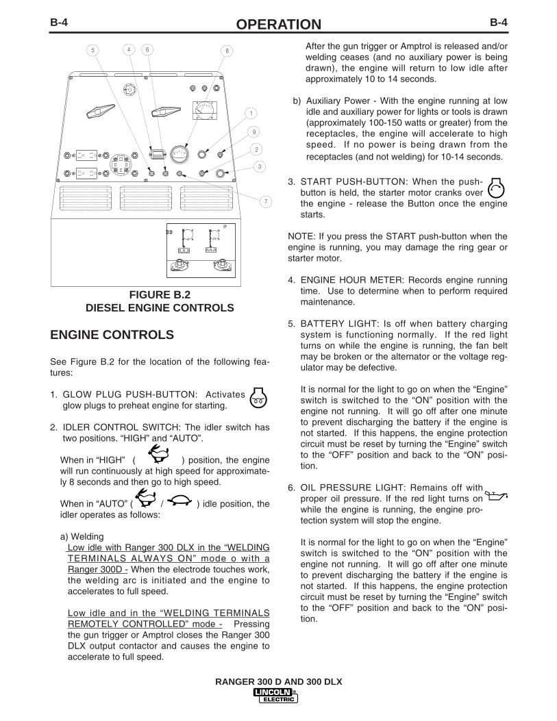
FIGURE B.2DIESEL ENGINE CONTROLS
ENGINE CONTROLS
See Figure B.2 for the location of the following fea-tures:
1. GLOW PLUG PUSH-BUTTON: Activatesglow plugs to preheat engine for starting.
2. IDLER CONTROL SWITCH: The idler switch hastwo positions. “HIGH” and “AUTO”.
When in “HIGH” ( ) position, the enginewill run continuously at high speed for approximate-ly 8 seconds and then go to high speed.
When in “AUTO” ( / ) idle position, theidler operates as follows:
a) Welding Low idle with Ranger 300 DLX in the “WELDINGTERMINALS ALWAYS ON” mode o with aRanger 300D - When the electrode touches work,the welding arc is initiated and the engine toaccelerates to full speed.
Low idle and in the “WELDING TERMINALSREMOTELY CONTROLLED” mode - Pressingthe gun trigger or Amptrol closes the Ranger 300DLX output contactor and causes the engine toaccelerate to full speed.
After the gun trigger or Amptrol is released and/orwelding ceases (and no auxiliary power is beingdrawn), the engine will return to low idle afterapproximately 10 to 14 seconds.
b) Auxiliary Power - With the engine running at lowidle and auxiliary power for lights or tools is drawn(approximately 100-150 watts or greater) from thereceptacles, the engine will accelerate to highspeed. If no power is being drawn from thereceptacles (and not welding) for 10-14 seconds.
3. START PUSH-BUTTON: When the push-button is held, the starter motor cranks overthe engine - release the Button once the enginestarts.
NOTE: If you press the START push-button when theengine is running, you may damage the ring gear orstarter motor.
4. ENGINE HOUR METER: Records engine runningtime. Use to determine when to perform requiredmaintenance.
5. BATTERY LIGHT: Is off when battery chargingsystem is functioning normally. If the red lightturns on while the engine is running, the fan beltmay be broken or the alternator or the voltage reg-ulator may be defective.
It is normal for the light to go on when the “Engine”switch is switched to the “ON” position with theengine not running. It will go off after one minuteto prevent discharging the battery if the engine isnot started. If this happens, the engine protectioncircuit must be reset by turning the “Engine” switchto the “OFF” position and back to the “ON” posi-tion.
6. OIL PRESSURE LIGHT: Remains off withproper oil pressure. If the red light turns onwhile the engine is running, the engine pro-tection system will stop the engine.
It is normal for the light to go on when the “Engine”switch is switched to the “ON” position with theengine not running. It will go off after one minuteto prevent discharging the battery if the engine isnot started. If this happens, the engine protectioncircuit must be reset by turning the “Engine” switchto the “OFF” position and back to the “ON” posi-tion.
RANGER 300 D AND 300 DLX
1
8
9
5 64
7
FE
3
2

B-5OPERATIONB-5
7. WATER TEMPERATURE LIGHT: Remainsoff under normal operating temperatures. Ifthe red light turns on, the engine protection systemwill stop the engine. The light will remain on whenthe engine is over temperature and the “Engine”switch is in the “ON” position (engine not running)but will go off as the engine cools.
8. FUEL LEVEL GAUGE: Displays the level of dieselfuel in the 10-gallon fuel tank.
9. ENGINE ON-OFF SWITCH: Energizes the fuelsolenoid in the ON position. In the STOP position,stops fuel flow to the injection pump and stops theengine.
ENGINE OPERATION
DO NOT RUN THE ENGINE AT EXCESSIVESPEEDS. The maximum allowable high idle speedfor the RANGER 300 is 3700 RPM, no load. Do NOTadjust the governor screw on the engine. Severe per-sonal injury and damage to the machine can result if itis operated at speeds above the maximum ratedspeed.------------------------------------------------------------------------Read and understand all safety instructions includedin the Kubota instruction manual that is shipped withyour RANGER 300.
BEFORE STARTING THE ENGINE
Check the engine oil level:See Figure D.1 for location of dipstick.
1. Be sure the machine is on a level surface.
2. Remove the engine oil dipstick and wipe it with aclean cloth. Reinsert the dipstick and check thelevel on the dipstick.
3. Add oil (if necessary) to bring the level up to the fullmark. Do not overfill.
4. Replace the dipstick.
Check and fill the engine fuel tank:
DIESEL fuel can cause fire orexplosion.• Stop engine when fueling.• Do not smoke when fueling.• Do not overfill tank.
• Keep sparks and flame away from tank.------------------------------------------------------------------------1. Remove the fuel tank cap.
2. Fill the tank approximately 4 inches (100 mm) fromthe top of the filler neck to allow for fuel expansion(observe the fuel gauge.) DO NOT FILL THETANK TO THE POINT OF OVERFLOW.
3. Replace the fuel tank cap and tighten securely.
RANGER 300 D AND 300 DLX
WARNING
WARNING

B-6OPERATIONB-6
NOTE: DO NOT allow the RANGER 300 to run out offuel. If it does, you will have to bleed the injec-tion system. See the Maintenance section ofthis manual and the Engine Operators Manualfor instructions on bleeding the fuel injectionsystem.
USE DIESEL FUEL ONLYPurchase diesel fuel in quantities that will be usedwithin 30 days, to assure freshness.------------------------------------------------------------------------
STARTING THE ENGINE
Remove all loads connected to the AC power recepta-cles and the welder before starting the diesel engine.------------------------------------------------------------------------1. Open the engine compartment door and check that
the fuel shutoff valve located above the clear plas-tic fuel filter housing is in the open position (lever inthe vertical position). See Figure B.3.
FIGURE B.3
2. Check for proper level of coolant in the plasticreserve overflow tank. The level should bebetween the full and the low marks.
3. Check for proper oil level on the oil dipstick. Closeengine compartment door.
4. Set “IDLER” switch to “AUTO”. /
5. Set the “ENGINE” switch to “ON”. Observe thatboth the oil pressure light and battery charger lightare on. Check the fuel gauge to make sure thatthere is an adequate fuel level (NEVER ALLOWTHE RANGER 300 D/DLX TO RUN OUT OFFUEL).
6. Press the “GLOW PLUG” button to pre-heatthe cylinders per the following table:
RANGER 300 D AND 300 DLX
CAUTION
CAUTION
Ambient Temperature
Above 50°F (10°C)
50°F (10°C) to 23°F(-5°C)
Below 23°F (-5°C)
Pre-Heat Time
NOT REQUIRED
Approximately 5 seconds
Approximately 10 seconds
CAUTIONNever press the Glow Plug button continuously formore than 20 seconds.------------------------------------------------------------------------
7. Release the "GLOW PLUG" button andpress the “START” button to crank theengine. Release when the engine starts.
8. Check that the indicator lights are off. If not, imme-diately stop the engine and investigate the indicat-ed problem.
9. Allow the engine to warm up at low idle speed forseveral minutes before applying a load and/orswitching to high idle. Allow a longer warm up timein cold weather.
NOTE:If the engine fails to start in 60 seconds orstops running the “ENGINE” switch must beswitched to “OFF” and then switched back to “ON”before attempting to restart the engine. This resetsthe engine protection circuit.
COLD WEATHER STARTING ANDOPERATION.
The Kubota engine used in the Ranger 300 can bestarted in temperatures as low as 5°F (-15°C). At tem-peratures below 23°F (-5° C), it is recommended thatNo. 1D diesel fuel be used in place of No. 2D. Allowengine to warm up before applying a load or switchingto HIGH idle.
STOPPING THE ENGINE
1. Remove all welding and generator power loadsand let the engine cool by running it for severalminutes at low idle.
2. Stop the engine by placing the Engine Switch inthe OFF position. This turns off the fuel solenoid.You can also stop the engine by turning off the fuelvalve located on the fuel filter housing.

B-7OPERATIONB-7
BREAK-IN PERIOD
Any engine will use a small amount of oil during its“break-in” period. For the diesel engine on theRANGER 300, break-in is about 50 running hours.
Check the oil every four hours during break-in.Change the oil after the first 50 hours of operation,every 100 hours thereafter. Change the oil filter at thesecond oil change.
During break-in, subject the RANGER 300 to moder-ate loads. Avoid long periods running at idle. Beforestopping the engine, remove all loads and allow theengine to cool several minutes.------------------------------------------------------------------------
TABLE B.1TYPICAL RANGER 300 FUEL CONSUMPTION
* DLX model only
WELDING OPERATION
The RANGER 300 machines can deliver from 45 to300 amps of constant current for AC/DC stick welding.The Ranger 300 DLX can deliver 45 to 300 amps ofconstant voltage current for DC semiautomatic wirefeed welding. The Ranger 300 D can deliver 45 to200 amps of constant voltage current for DC semiau-tomatic wire feed welding. AC/DC constant currentTIG welding is possible across the entire range from45 to 300 amps although 250 amps is the maximumrecommended for AC TIG welding of aluminum.
Output can be adjusted by setting the POLARITYSWITCH, the OUTPUT RANGE dial, and the FINECONTROL dial on the output control panel to the set-tings that are best for your selected welding process.
RANGER 300 D AND 300 DLX
CAUTION
Low Idle - No Load2000 RPM
High Idle - No Load3700 RPM
AC CC Weld Output300 Amps @ 25 Volts
DC CC Weld Output300 Amps @ 25 Volts
DC CV Weld Output300 Amps @ 28 Volts*
Auxiliary Power,12,000 kVA
.30 gallons/hour(1.0 liters/hour)
.60 gallons/hour(2.2 liters/hour)
1.1 gallons/hour(4.2 liters/hour)
1.2 gallons/hour(4.6 liters/hour)
.90 gallons/hour(3.6 liters/hour)
1.3 gallons/hour(4.9 liters/hour)
Do not attempt to use this equipment until youhave thoroughly read the engine manufacturer’smanual supplied with your welder. It includesimportant safety precautions, detailed enginestarting, operating and maintenance instructions,and parts lists.------------------------------------------------------------------------
ELECTRIC SHOCK can kill.• Do not touch electrically live parts or
electrode with skin or wet clothing.• Insulate yourself from work and
ground• Always wear dry insulating gloves.
------------------------------------------------------------------------FUMES AND GASES can be dangerous.• Keep your head out of fumes.• Use ventilation or exhaust to remove
fumes from breathing zone.
------------------------------------------------------------------------MOVING PARTS can injure.• Do not operate with doors open orguards off.• Stop engine before servicing.• Keep away from moving parts.
------------------------------------------------------------------------WELDING SPARKS can cause fire orexplosion.• Keep flammable material away.
------------------------------------------------------------------------ARC RAYS can burn.• Wear eye, ear and body protection.
------------------------------------------------------------------------See additional warning informationthroughout this operator’s manual.
WARNING

B-8OPERATIONB-8
AC/DC STICK (CONSTANT CURRENT)WELDING
1. Remove the flange nuts from output terminals andplace the work and electrode welding cables overthe terminals. See Figure B.4. Replace and tight-en the flange nuts securely. Be sure the connec-tions are tight.
2. Select the appropriate electrode. See “WeldingTips 1" included with your RANGER 300.
3. Attach the work clamp securely to the work you arewelding.
4. Insert the electrode into the electrode holder.
5. Set the IDLER CONTROL to AUTO and start thediesel engine.
6. Set the RANGE switch to a setting equal to orslightly lower than the welding current recommend-ed for the electrode being used. For the best weld-ing performance, always set the RANGE switch tothe lowest CC-blue setting that will give the desiredweld current. This will assure that the OUTPUTdial is set towards the high end of the dial. If theOUTPUT dial is set at 10 and the welding currentis to low, move the RANGE switch to the next high-est setting.
7. Set the POLARITY switch to the desired polarity(CC-blue setting).
8. Set the OUTPUT control. For stick welding,always use a setting between 5 and 10 on the dial(blue range).
9. Strike an arc and begin welding. The OUTPUTcontrol can be adjusted while welding.
DO NOT change the RANGE switch setting whilewelding. This can result in damage to the switch.------------------------------------------------------------------------
FIGURE B.4WELDING CIRCUIT CONNECTIONS
AFTER YOU FINISH WELDING:
1. Stop the engine.
2. Allow the electrode and work to cool completely.
3. Remove the work clamp from the work.
4. Remove any remaining piece of electrode from theelectrode holder.
5. If you are finished using the RANGER 300 forwelding, disconnect the welding cables from theweld output terminals. Reattach the flange nutsand leave them on the terminals.
RANGER 300 D AND 300 DLX
CAUTION
RANGE SETTINGON MACHINE
ACTUALCURRENT RANGE
5075100140180225300
30 to 50 AMPS50 to 75 AMPS70 to 100 AMPS95 to 140 AMPS110 to 180 AMPS130 to 225 AMPS160 to 300 AMPS
FE
OUTPUT TERMINALS

B-9OPERATIONB-9
AC/DC TIG (CONSTANT CURRENT)WELDING
1. Connect the K930-1 TIG Module to the RANGER 300.Follow the installation instructions provided with the kit.
2. Refer to the instruction manual with the TIG module (IM528) for operation with a RANGER 300. And propermachine settings.
3. Set the RANGE switch to the appropriate setting for theelectrode you are using. Refer to IM-528 with the TIGmodule or refer to Table B.2 for AC TIG welding.
4. Set the POLARITY SWITCH to the desired polarity.
5. Do not AC TIG weld on the 250 AC range setting. Theoutput current may exceed the rating of the RANGER300.
6. Start the arc and begin welding.
NOTE: When using the RANGER 300 for AC TIG weldingof aluminum, the TIG Module is to be set for CON-TINUOUS HF.
AFTER YOU FINISH WELDING:
1. Stop the engine.
2. Allow the electrode and work to cool completely.
3. Remove the work clamp from the work.
TABLE B.2AC TIG WELDING
TIG ELECTRODE / RANGE SETTINGS
(1) The welding current will be approximately 200 amps with the range switch set at120 and the OUTPUT CONTROL set at 10. Do not use a range setting higherthan 120 for AC TIG welding with a pure tungsten electrode.
DC WIRE FEED WELDING (CV)WITH RANGER 300 DLX
1. Connect one of the following: the LN-25, LN-7 orLN-8 Wire Feeder.
2. Some recommended Innershield electrodes are:.068 NR-211MP, .068 NR-232, NR-203 series,5/64 NR-311, and 5/64 NS-3M also Lincore® 33and 55 hardfacing electrodes can be used. Cablelength and other conditions can affect the ultimateresults of this application. Request Lincoln publi-cation N-675 for additional information.
Recommended Outershield electrodes are .045(1.1 mm), .052 (1.3 mm), and 1/16 (1.6 mm)Outershield 71 and 1/16 (1.6 mm) Outershield 70.Request Lincoln publication GS-200 for additionalinformation.
For MIG welding, the recommended electrodes are.030 (0.8 mm), .035 (0.9 mm) and .045 (1.1 mm) L-50 and L-56. You must use a blended shieldinggas such as C25 (75% Argon, 25% CO2 ).Request Lincoln publication GS-100 for additionalinformation.
3. Set the IDLER CONTROL to “AUTO” for the LN-25“HIGH” for the LN-7 or LN-8 and start the dieselengine.
4. Set the RANGE switch to either HIGH, MEDIUMHIGH, MEDIUM LOW, or LOW (CV-red) depend-ing on your wire size and speed.
5. Set the POLARITY SWITCH to either WIRE FEEDDC+ or WIRE FEED DC (red), depending on theelectrode.
6. Set the OUTPUT control to a setting between 1and 10 that gives the most stable arc for the appli-cation. Try a higher RANGE switch setting if thearc is unstable.
7. Strike an arc and begin welding. The OUTPUTcontrol can be adjusted while welding. DO NOTchange the RANGE switch setting while welding.This can result in damage to the switch.
AFTER YOU FINISH WELDING:
1. Stop the engine.
2. Allow the work to cool completely.
3. Remove the work clamp from the work.
RANGER 300 D AND 300 DLX
Pure (EWP)Tungsten Diameter
“Range”Switch Settings
AppropriateWelding Current
1/8”
3/32”
1/16”
75, 100 or 140(1)
50, 75 or 100
50, 75 or 100
100 - 200 amps
50 - 100 amps
45 - 150 amps
1% ThoriatedTungsten Diameter
“Range”Switch Settings
AppropriateWelding Current
1/8”
3/32”
1/16”
100, 140 or 180
50, 100 or 140
50 or 100
160 - 250 amps
100 - 180 amps
60 - 120 amps

B-10OPERATIONB-10
DC WIRE FEED WELDING (CV)WITH RANGER 300D
1. Connect an LN-25 with internal contactor to theRanger 300D.
2. The only Innershield electrode recommended foruse with the Ranger 300D is NR211MP. The elec-trode sizes and welding ranges that can be usedwith the Ranger 300D are shown in the followingtable:
The Ranger 300 D is recommended for limited "MIG"welding (GMAW - gas metal arc welding). The recom-mended electrodes are .030 and .035 L-50 and L-56.They must be used with a blended shielding gas suchas C25 (75% Argon - 25% CO2). The .035 diameterelectrode gives improved starting compared to .030diameter. The welding ranges that can be used withthe Ranger 300D are shown in the following table:
3. Set the IDLER control to AUTO.
4. Set the RANGER switch to the WIRE FEED (CV-red setting).
5. Set the POLARITY SWITCH to either WIRE FEEDDC+ (red) or WIRE FEED DC- (red), depending onthe electrode.
6. Set the OUTPUT control to a setting between 1and 10 that gives the most stable arc for the appli-cation.
7. Strike an arc and begin welding. the OUTPUTcontrol can be adjusted while welding. DO NOTchange the RANGE switch setting while welding.This can result in damage to the switch.
AFTER YOU FINISH WELDING:
1. Stop the engine
2. Allow the work to cool completely
3. Remove the work clamp from the work
CARBON ARC GOUGING (CONSTANT CURRENT)
1. The recommended electrode ia a 3/16” (4.8 mm)dia. carbon
2. Set the RANGE switch to 300
3. Set the POLARITY switch to DC+ (cc - blue setting)
4. Set the OUTPUT control to 10
5. Strike an arc and begin gouging
After you finish gouging:
1. Stop the engine
2. Allow the electrode and work to cool completely
3. Remove the work clamp from the work
RANGER 300 D AND 300 DLX
ElectrodeDiameter
Wire Speedin. / min.
ApproximateCurrent Range
.035”
.045”
.068”
70 - 110
70 - 130
40 - 90
60 - 120 amps
120 - 170 amps
125 - 210 amps
ElectrodeDiameter
Wire Speedin. / min.
ApproximateCurrent Range
.030”
.035”
150 - 450
100 - 350
80 - 170 amps
80 - 190 amps

B-11OPERATIONB-11
RANGER 300 D AND 300 DLX
SUMMARY OF WELDING PROCESSES AND MACHINE SETTINGSTABLE B.3
SUMMARY OF WELDING PROCESSES FOR RANGER 300 DLX
CONTROLCABLE &DIAGRAM
IDLEMODE
OUTPUTCONTROLSWITCH
WELDINGTERMINALS
SWITCH
ELECTRODEWHEN NOTWELDING
TO START WELDINGPROCESS
STICK - CCCARBON ARCGOUGING - CC
TIG - CCK930-1 TIG MODULE /K936-1 CONTROL CABLE
WIRE FEED - CV,LN-25 WITH 42VREMOTE CON-TROL KIT
WIRE FEED - CV,LN-25 WITHINTERNALCONTACTOR
WIRE FEED - CV,LN-742
WIRE FEED - CV,LN-7 or LN-8
K487-15 WIRE FEED-CV SPOOL GUN / K488CONTROL MODULE
Touch electrode to work.Welding starts immediatelyand engine goes to high idle.
Press Amptrol. Weldingstarts immediately.
Press gun trigger, Ranger300 DLX contactor closes.Welding starts immediatelyand engine goes to high idle.
Press gun trigger, LN-25contactor closes. Weldingstarts immediately and enginegoes to high idle.
Press gun trigger, Ranger300 DLX contactor closes.Welding starts immediatelyand engine goes to high idle.
Press gun trigger, Ranger300 DLX contactor closes.Welding starts immediately.
Press gun trigger, Ranger300 DLX contactor closes.Welding starts immediately.
NO
YESS23732-9
YESS23732-3
NOS23732-1S23732-2
YESS23732-5
YESS23732-4S23732-6
YESS23732-8
AUTO
AUTO
AUTO
AUTO
AUTO
HIGH
HIGH
ATWELDER
REMOTE
REMOTE
ATWELDER
REMOTE
REMOTE
AT WELDER
ALWAYSON
REMOTE
REMOTE
ALWAYSON
REMOTE
REMOTE
REMOTE
HOT
COLD
COLD
COLD
COLD
COLD
COLD

B-12OPERATIONB-12
RANGER 300 D AND 300 DLX
SUMMARY OF WELDING PROCESSES AND MACHINE SETTINGSTABLE B.4
SUMMARY OF WELDING PROCESSES FOR RANGER 300 D
CONTROLCABLE &DIAGRAM
IDLEMODE
OUTPUTCONTROLSWITCH
ELECTRODEWHEN NOTWELDING
TO START WELDINGPROCESS
STICK - CCCARBON ARCGOUGING - CC
TIG - CCK930-1 TIG MODULE /K936-1 CONTROL CABLE
WIRE FEED - CV,LN-25 / INTERNALCONTACTOR
WIRE FEED - CV,LN-7 / K240CONTACTOR KIT
Touch electrode to work.Welding starts immediatelyand engine goes to high idle.
Press Amptrol. Weldingstarts immediately.
Press gun trigger, LN-25contactor closes. Electrodetouches work, welding startsimmediately and engine goesto high idle.
Press gun trigger, K240contactor closes. Weldingstarts immediately.
NO
YESS23732-10
NOS23732-1S23732-2
YESS23732-11
AUTO
AUTO
AUTO
HIGH
ATWELDER
REMOTE
ATWELDER
ATWELDER
HOT
HOT
COLD
COLD

B-13OPERATIONB-13
AUXILIARY POWER
The Ranger 300 can provide up to 12,000 watts of120/240 volts AC, Single phase 60 HZ power for con-tinuous use. The front of the machine includes threereceptacles for connecting AC power Plugs, one 50amp 120/240 volt NEMA 14-50R receptacle and two15 amp 120 volt NEMA 5-15R receptacles. Do notconnect any plugs that connect to the power recepta-cles in parallel.
Start the engine and set the "IDLER" control switch tothe desired operating mode. Set the "CONTROL" to10. Voltage is now correct at the receptacles for auxil-iary power.
Most single phase motors through 2.0 HP can bestarted if there is no load on the motor or other loadconnected to the machine. Since the full load currentof a 2.0 HP motor is typically 18 to 20 Amps when
operated at 120 V or 9 to 11 Amps when operated at240 V, it should be connected to the 120/240 dualvoltage receptacle. The full load current of a 1.5 HPmotor is typically 15 to 17 Amps when operated at 120V or 7.5 to 8.5 Amps when operated at 240 V, it alsoshould be connected to the 120/240 dual voltagereceptacle. a 1.0 HP that draws less than 15 Amps at120 V can be plugged into one of the 120 V duplexreceptacles.
SIMULTANEOUS WELDING AND POWERLOADS
Auxiliary power ratings are with no welding load.Simultaneous welding and power loads are permittedby the following table. The permissible currentsshown assume that current is being drawn from eitherthe 120 volt or 240 volt supply (not both at the sametime).
RANGER 300 D AND 300 DLX
OutputSelectorSetting
WeldingOutputAmps
PermissiblePower Watts(Unity Power
Factor)
PermissibleAuxiliary Current in
Amperes @ 120V
PermissibleAuxiliary Current in
Amperes @ 240V
0132027333842
1740
1327
833
025
0254053606060
3360
2560
1760
050
NONE30004800640080009000
10,000
40009600
30008800
20008000
06000
3002251801401007550
20060
22580
250100
300150
3002251801401007550
CV LOW (300 DLX)CV (300 D)
CV MED. LOW(300 DLX)
CV MED. HIGH(300 DLX)
CV HIGH(300 DLX)
RANGER 300 SIMULTANEOUS WELDING AND POWER LOADS (OUTPUT CONTROL SET AT 10)
TABLE B.5
NOTE: Voltage and permissible watts decrease as "CONTROL" is adjusted to settings less than 10. It is recommended thatat settings less than 10, only incandescent lighting loads be connected to the auxiliary power receptacles.

B-14OPERATIONB-14
120/240 VOLT DUAL VOLTAGERECEPTACLE
The 120/240 volt receptacle can supply up to 50 ampsof 240 volt power to a two wire circuit, up to 50 ampsof 120 volt power from each side of the three wire cir-cuit, (up to 100 amps total). Do not connect the 115volt circuits in parallel. Current sensing for the auto-
matic idle feature is in both legs of the three wire cir-cuit as shown below.
FIGURE B.5
120V DUPLEX RECEPTACLES
The 120V auxiliary power receptacles should only beused with three wire grounding type plugs or approveddouble insulated tools with two wire plugs.
RANGER 300 D AND 300 DLX
GND
120 V
120 V
240 V
Maximum Current Draw from 120V DuplexReceptacles - No Welding
EACH HALF OFEACH 120V
DUPLEX
TOTAL FROMONE 120VDUPLEX
TOTAL FROMBOTH 120VDUPLEXES
240 V LOAD FROMFULL KVA
RECEPTACLE
0
20 AMPS
30 AMPS
40 AMPS
50 AMPS
15 AMPS
15 AMPS
15 AMPS
15 AMPS
0
30 AMPS
30 AMPS
30 AMPS
20 AMPS
0
60 AMPS
60 AMPS
40 AMPS
20 AMPS
0
Maximum Current Draw from Optional 120VGFCI Duplex Receptacles - No Welding
EACH HALF OFEACH 120V
DUPLEX
TOTAL FROMONE 120VDUPLEX
TOTAL FROMBOTH 120VDUPLEXES
240 V LOAD FROMFULL KVA
RECEPTACLE
0
35 AMPS
50 AMPS
15 AMPS
15 AMPS
0
15 AMPS
15 AMPS
0
30 AMPS
30 AMPS
0
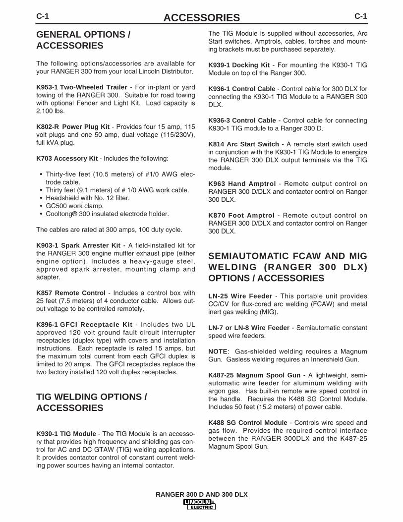
C-1ACCESSORIESC-1
GENERAL OPTIONS / ACCESSORIES
The following options/accessories are available foryour RANGER 300 from your local Lincoln Distributor.
K953-1 Two-Wheeled Trailer - For in-plant or yardtowing of the RANGER 300. Suitable for road towingwith optional Fender and Light Kit. Load capacity is2,100 lbs.
K802-R Power Plug Kit - Provides four 15 amp, 115volt plugs and one 50 amp, dual voltage (115/230V),full kVA plug.
K703 Accessory Kit - Includes the following:
• Thirty-five feet (10.5 meters) of #1/0 AWG elec-trode cable.
• Thirty feet (9.1 meters) of # 1/0 AWG work cable.• Headshield with No. 12 filter.• GC500 work clamp.• Cooltong® 300 insulated electrode holder.
The cables are rated at 300 amps, 100 duty cycle.
K903-1 Spark Arrester Kit - A field-installed kit forthe RANGER 300 engine muffler exhaust pipe (eitherengine option). Includes a heavy-gauge steel,approved spark arrester, mounting clamp andadapter.
K857 Remote Control - Includes a control box with25 feet (7.5 meters) of 4 conductor cable. Allows out-put voltage to be controlled remotely.
K896-1 GFCI Receptacle Kit - Includes two ULapproved 120 volt ground fault circuit interrupterreceptacles (duplex type) with covers and installationinstructions. Each receptacle is rated 15 amps, butthe maximum total current from each GFCI duplex islimited to 20 amps. The GFCI receptacles replace thetwo factory installed 120 volt duplex receptacles.
TIG WELDING OPTIONS / ACCESSORIES
K930-1 TIG Module - The TIG Module is an accesso-ry that provides high frequency and shielding gas con-trol for AC and DC GTAW (TIG) welding applications.It provides contactor control of constant current weld-ing power sources having an internal contactor.
The TIG Module is supplied without accessories, ArcStart switches, Amptrols, cables, torches and mount-ing brackets must be purchased separately.
K939-1 Docking Kit - For mounting the K930-1 TIGModule on top of the Ranger 300.
K936-1 Control Cable - Control cable for 300 DLX forconnecting the K930-1 TIG Module to a RANGER 300DLX.
K936-3 Control Cable - Control cable for connectingK930-1 TIG module to a Ranger 300 D.
K814 Arc Start Switch - A remote start switch usedin conjunction with the K930-1 TIG Module to energizethe RANGER 300 DLX output terminals via the TIGmodule.
K963 Hand Amptrol - Remote output control onRANGER 300 D/DLX and contactor control on Ranger300 DLX.
K870 Foot Amptrol - Remote output control onRANGER 300 D/DLX and contactor control on Ranger300 DLX.
SEMIAUTOMATIC FCAW AND MIGWELDING (RANGER 300 DLX)OPTIONS / ACCESSORIES
LN-25 Wire Feeder - This portable unit providesCC/CV for flux-cored arc welding (FCAW) and metalinert gas welding (MIG).
LN-7 or LN-8 Wire Feeder - Semiautomatic constantspeed wire feeders.
NOTE: Gas-shielded welding requires a MagnumGun. Gasless welding requires an Innershield Gun.
K487-25 Magnum Spool Gun - A lightweight, semi-automatic wire feeder for aluminum welding withargon gas. Has built-in remote wire speed control inthe handle. Requires the K488 SG Control Module.Includes 50 feet (15.2 meters) of power cable.
K488 SG Control Module - Controls wire speed andgas flow. Provides the required control interfacebetween the RANGER 300DLX and the K487-25Magnum Spool Gun.
RANGER 300 D AND 300 DLX

C-2ACCESSORIESC-2
SEMIAUTOMATIC FCAW AND MIGWELDING (RANGER 300 D) OPTIONS / ACCESSORIES
LN-25 Wire Feeder - The recommended wire feederfor use with the Ranger 300 D is the K449 LN-25.This portable unit provides CC/CV for flux-cored arcwelding (FCAW) and metal inert gas welding (MIG).for remote control use either a K857 Remote ControlKit (25 ft.) or a K444-1 Remote Voltage Control Kit (25ft.) which mounts inside the LN-25.
RANGER 300 D AND 300 DLX

D-1MAINTENANCED-1
KUBOTA ENGINE MAINTENANCESCHEDULE
TABLE D.1
(1) Replace air filter element after 600 hours of operation or sooner underdusty operating conditions.
(2) If the engine is operated under heavy load, in high ambient temperatures,or under dusty conditions, change the oil and oil filter every 100 hours.
Refer to your Kubota Operator's Manual for periodicmaintenance at 500 hours and beyond.
KUBOTA ENGINE MAINTENANCECOMPONENTS
TABLE D.2
RANGER 300 D AND 300 DLX
Have qualified personnel do the maintenancework. Turn the engine off before working insidethe machine. In some cases, it may benecessary to remove safety guards to performrequired maintenance. Remove guards onlywhen necessary and replace them when themaintenance requiring their removal iscomplete. Always use the greatest care whenworking near moving parts.
Do not put your hands near the engine coolingblower fan. If a problem cannot be corrected byfollowing the instructions, take the machine tothe nearest Lincoln Field Service Shop.
-----------------------------------------------------------------------ELECTRIC SHOCK can kill.• Do not touch electrically live parts or
electrode with skin or wet clothing.• Insulate yourself from work and
ground• Always wear dry insulating gloves.
------------------------------------------------------------------------ENGINE EXHAUST can kill.• Use in open, well ventilated areas or
vent exhaust outside.
------------------------------------------------------------------------MOVING PARTS can injure.• Do not operate with doors open or
guards off.• Stop engine before servicing.• Keep away from moving parts.
------------------------------------------------------------------------
See additional warning informationthroughout this operator’s manual andthe Engine manual as well.
-----------------------------------------------------------
WARNING
FREQUENCY
Daily or BeforeStarting Engine
Every 50 Hours
Every 100 Hours
Every 200 Hours
Every 400 Hours
MAINTENANCE REQUIRED
• Fill fuel tank.• Check oil level.• Check air cleaner for dirty, loose,
or damaged parts.• Check air intake and cooling
areas, clean as necessary.
• Check fuel lines and clamps.
• Clean air filter element. (1)
• Check battery electrolyte level.• Check fan belt tightness.
• Change engine oil. (2)
• Replace oil filter cartridge. (2)
• Check radiator hoses.
• Replace fuel filter element.
ITEM
Oil Filter Element
Air Cleaner Element
Fuel Filter Element
MAKE AND PART NUMBER
Kubota 16271-32092Fram PH 3593A
Donaldson P148970
Kubota 15231-43560Fram C6921

D-2MAINTENANCED-2
ROUTINE AND PERIODIC ENGINEMAINTENANCE
To prevent the engine from accidentally starting, dis-connect the negative battery cable before servicingthe engine.------------------------------------------------------------------------
See Table D.1 for a summary of maintenance inter-vals for the items listed below. More frequent servicemay be required, depending on your specific applica-tion and operating conditions. See the Kubota EngineOperator's Manual for further information
OILCheck the oil level before starting engine ordaily. BE SURE TO MAINTAIN THE OIL LEVEL.Change the oil for the first time after 50 hours of oper-ation. Then, under normal operating conditions,change the oil as specified in the maintenance sched-ule.
CHANGING THE OIL
Change the oil, while the engine is still warm, as fol-lows:
1. Drain the oil from the drain plug located on theengine bottom, as shown in Figure D.1.
2. Replace the plug and tighten it securely.
3. Remove the oil fill cap and add oil until the levelreaches the full mark on the dipstick. The quantityof oil required for an oil and oil filter change is 5.4quarts (5.1 L). Use oil that is rated for dieselengine service (API classification CD/CE). UseSAE viscosity grades per the following table:
4. Reinstall the oil fill cap and the dipstick and startthe engine. Run for several minutes and stopengine - Wait 5 minutes to allow the oil to comedown to the oil pan and check oil level again.
FIGURE D.1OIL COMPONENT LOCATIONS
OIL FILTER
Change the oil filter the first time after 50 hours ofoperation. Then, under normal operating conditions,change the oil filter at every oil change.
Change the oil filter as follows:
1. Drain the oil from the engine and allow the oil filterto drain.
2. Remove the old filter (spin it off) and discard it.Wipe off the filter mounting surface and adapter.
3. Apply a thin coat of new oil to the rubber gasket onthe new oil filter.
4. Spin the new filter on to the mounting adapter untilthe gasket just touches the mounting surface, thenturn it down another 1/2 to 3/4 turn. Do not over-tighten the new filter.
5. Refill the engine with the proper amount and typeof oil as described in the CHANGING THE OILsection. Start the engine and check for leaksaround the filter element. Correct any leaks (usu-ally by retightening the filter, but only enough tostop leaks) before placing the RANGER 300 backin service.
6. If there are no leaks, stop the engine and recheckthe oil level. If necessary, add oil to bring the levelup to the FULL mark, but do not overfill.
RANGER 300 D AND 300 DLX
WARNING
Ambient Temperature
Above 25°C (77°F)
0°C (32°F) to 25°C(77°F)
Below 0°C (32°F)
Viscosity Grades
SAE 10W-30, SAE10W-40 or SAE30
SAE 10W-30, SAE10W-40 or SAE20
SAE 10W-30, SAE10W-40 or SAE10
OIL DRAIN PLUG
OIL FILTER
OIL FILL CAPOIL LEVELDIP STICK

D-3MAINTENANCED-3
FUELAt the end of each day’s use, refill the fuel tankto minimize moisture condensation and dirt contami-nation in the fuel line. Do not overfill; leave room forthe fuel to expand.
Use only fresh, No. 2 grade DIESEL fuel. Do not usekerosene.
See the Kubota Engine Operator's Manual for instruc-tions on replacing the fuel filter.
BLEEDING THE FUEL SYSTEM
You will need to bleed air from the fuel system anytime the fuel filter or fuel lines have been detachedand refitted; after the fuel tank has been run out offuel; or before using the engine after long storage.Bleed the fuel system as follows:
To avoid personal injury, do not bleed a hot engine.This could cause fuel to spill onto a hot exhaust mani-fold, creating a danger of fire.------------------------------------------------------------------------
Refer to Figure D.2
1. Fill the fuel tank, Open the fuel cock.
2. Open the air vent plug on the fuel injection pumptwo turns using a 10mm wrench.
3. Move the fuel feed pump lever by hand until fuelflows out of the air vent plug.
4. Tighten the air vent plug.
AIR CLEANER
The Kubota diesel engine is equipped with a dry typeair filter. Never apply oil to it. Service the air cleaneras follows:
1. Remove the dust cup from the bottom of the aircleaner housing. Clean out any accumulated dust.
2. If dust is sticking to the element, blow compressedair through the element from the inside out. Turnthe element as you apply air. Air pressure shouldbe under 99 psi (68 newton/cm2). Replace the fil-ter if there is carbon or oil on the element.
3. Replace the element at least every 600 hours ofoperation and sooner under dusty conditions.
TIGHTENING THE FAN BELT
If the fan belt is loose, the engine can overheat andthe battery lose its charge. Check tightness by press-ing on the belt midway between the pulleys. It shoulddeflect bout .25 in. under a load of 20 lbs. (9 Kg) (6mm).
COOLING SYSTEM
HOT COOLANT can burn skin.
• Do not remove cap if radiator ishot.
------------------------------------------------------------------------
Check the coolant level by observing the level in theplastic reserve overflow tank. Add 50/50 antifreeze /water solution if the level is close to or below the"LOW" mark. do not fill above the "FULL" mark.Remove radiator cap and add coolant to radiator ifoverflow tank is empty.
To drain the coolant, open the petcock at the bottomor the radiator. Open the radiator cap to allow com-plete drainage. (Tighten the petcock and refill with a50/50 antifreeze/water solution.) Use an automotivegrade (low silicate) ethylene glycol antifreeze. Thecooling system capacity is 5.4 quarts (5.1L.). Replaceand tighten the radiator cap.
RANGER 300 D AND 300 DLX
WARNING
AIR VENT PLUG
FUEL FEED PUMP LEVERFIGURE D.2
FUEL BLEEDING COMPONENT LOCATIONS
WARNING

D-4MAINTENANCED-4
Always premix the antifreeze and clean tap waterbefore adding to the radiator or the overflow tank. It isvery important that a precise 50/50 solution be usedwith this engine year round. This gives proper coolingduring hot weather and freezing protection to -34° F (-37° C).
Cooling solution exceeding 50% ethylene glycol canresult in engine overheating and damage to theengine. Coolant solution must be premixed beforeadding to radiator.------------------------------------------------------------------------
Periodically remove the dirt from the radiator fins.
Periodically check the fan belt and radiator hoses.Replace if signs of deterioration are found.
BATTERY MAINTENANCE
GASES FROM BATTERY can explode.
● Keep sparks, flame and cigarettesaway from battery.
To prevent EXPLOSION when:
● INSTALLING A NEW BATTERY — disconnectnegative cable from old battery first and connect tonew battery last.
● CONNECTING A BATTERY CHARGER —remove battery from welder by disconnecting nega-tive cable first, then positive cable and batteryclamp. When reinstalling, connectnegative cable last. Keep well ventilated.
● USING A BOOSTER — connect positive lead tobattery first then connect negative lead to negativebattery lead at engine foot.
BATTERY ACID can burn eyes andskin.
● Wear gloves and eye protection andbe careful when working near battery.
● Follow instructions printed on battery.
To prevent ELECTRICAL DAMAGE when:a) Installing a battery.b) Using a booster.
Use correct polarity - Negative Ground.
To prevent BATTERY DISCHARGE, if you have an ignition switch, turn it off when engine is notrunning.
------------------------------------------------------------------------
CLEANING THE BATTERY
Keep the battery clean by wiping it with a damp clothwhen dirty. If the terminals appear corroded, discon-nect the battery cables and wash the terminals with anammonia solution or a solution of 1/4 pound (0.1113kg) of baking soda and 1 quart (0.946 l) of water. Besure the battery vent plugs (if equipped) are tight sothat none of the solution enters the cells.
After cleaning, flush the outside of the battery, the bat-tery compartment, and surrounding areas with clearwater. Coat the battery terminals lightly with petroleumjelly or a non-conductive grease to retard corrosion.
Keep the battery clean and dry. Moisture accumula-tion on the battery can lead to more rapid dischargeand early battery failure.
CHECKING ELECTROLYTE LEVEL
If battery cells are low, fill them to the neck of the fillerhole with distilled water and recharge. If one cell islow, check for leaks.
The battery is a group 45, with a rating of 495 coldcranking amps.
RANGER 300 D AND 300 DLX
CAUTION
WARNING

D-5MAINTENANCED-5CHARGING THE BATTERY
When you charge, jump, replace, or otherwise con-nect battery cables to the battery, be sure the polarityis correct. Improper polarity can damage the chargingcircuit. The RANGER 300 positive (+) battery termi-nal has a red terminal cover.
If you need to charge the battery with an externalcharger, disconnect the negative cable first, then thepositive cable before you attach the charger leads.after the battery is charged, reconnect the positivebattery cable first and the negative cable last. Failureto do co can result in damage to the internal chargercomponents.
Follow the instructions of the battery charger manu-facturer for proper charger settings and chargingtime.
WELDER / GENERATOR MAINTENANCE
STORAGE
Store the RANGER 300 in clean, dry protected areas.
CLEANING
Blow out the generator and controls periodically withlow pressure air. do this at least once a week in par-ticularly dirty areas.
OUTPUT RANGE SELECTOR ANDPOLARITY SWITCHES:
Switch contacts should not be greased. To keep con-tacts clean, rotate the switch though its entire rangefrequently. Good practice is to turn the handle frommaximum to minimum setting twice each morningbefore starting to weld.
BRUSH REMOVAL AND REPLACEMENT
It is normal for the brushes and slip rings to wear anddarken slightly. Inspect the brushes when a generatoroverhaul is necessary.
Do not attempt to polish slip rings while the engine isrunning.------------------------------------------------------------------------
RANGER 300 D AND 300 DLX
WARNING

E-1TROUBLESHOOTINGE-1
RANGER 300 D AND 300 DLX
If for any reason you do not understand the test procedures or are unable to perform the tests/repairs safely, contact yourLocal Lincoln Authorized Field Service Facility for technical troubleshooting assistance before you proceed.
CAUTION
WARNINGELECTRIC SHOCK can kill.• Do not touch electrically live parts such as output
terminals or internal wiring.
ENGINE EXHAUST can kill.• Use in open, well ventilated areas or vent exhaust
outside.
MOVING PARTS can injure.• Do not operate with doors open or guards off.• Stop engine before servicing.• Keep away from moving parts.
• Remove guards only when necessary and replace when workrequiring removal is complete.
• Only qualified personnel should install, use or service thisequipment.
This Troubleshooting Guide is provided to help youlocate and repair possible machine malfunctions.Simply follow the three-step procedure listed below.
Step 1. LOCATE PROBLEM (SYMPTOM).Look under the column labeled “PROBLEM (SYMP-TOMS)”. This column describes possible symptomsthat the machine may exhibit. Find the listing thatbest describes the symptom that the machine isexhibiting.
Step 2. POSSIBLE CAUSE.The second column labeled “POSSIBLE CAUSE” liststhe obvious external possibilities that may contributeto the machine symptom.
Step 3. RECOMMENDED COURSE OF ACTIONThis column provides a course of action for thePossible Cause, generally it states to contact yourlocal Lincoln Authorized Field Service Facility.
If you do not understand or are unable to perform theRecommended Course of Action safely, contact yourlocal Lincoln Authorized Field Service Facility.
HOW TO USE TROUBLESHOOTING GUIDE
Service and Repair should only be performed by Lincoln Electric Factory Trained Personnel.Unauthorized repairs performed on this equipment may result in danger to the technician andmachine operator and will invalidate your factory warranty. For your safety and to avoid ElectricalShock, please observe all safety notes and precautions detailed throughout this manual.
__________________________________________________________________________
WARNING

E-2TROUBLESHOOTINGE-2
RANGER 300 D AND 300 DLX
Observe all Safety Guidelines detailed throughout this manual
If for any reason you do not understand the test procedures or are unable to perform the tests/repairs safely, contact yourLocal Lincoln Authorized Field Service Facility for technical troubleshooting assistance before you proceed.
CAUTION
PROBLEMS(SYMPTOMS)
POSSIBLE AREAS OFMISADJUSTMENTS(S)
RECOMMENDEDCOURSE OF ACTION
Major Physical or Electrical Damageis Evident.
Engine will not "crank".
Engine will "crank" but not start.
Engine shuts down shortly afterstarting.
Engine shuts down while under load.
Battery does not stay charged.
1. Battery is low.2. Loose battery cable connections.3. Faulty engine starter motor.
1. Fuel shut off valve is in off posi-tion.
2. Out of fuel.
3. Engine switch in "OFF" position.4. High coolant temperature
(Indicator light lit).5. Faulty fuel solenoid or faulty PC
board.
1. Low oil level. Oil pressure indica-tor light will flash while engine isrunning.
2. Circuit breaker CB9 located inengine compartment is open. Oilpressure and charging indicatorlights will not be on when engineswitch is ON and engine is notrunning if CB9 is tripped.
1. High coolant temperature(Indicator light lit).
1. Faulty battery.2. Loose connections at battery or
alternator.3. Loose fan belt.4. Faulty engine alternator.
1. Contact your Local Lincoln AuthorizedField Service Facility.
1. Charge Battery.2. Inspect, clean and tighten.3. Contact authorized Kubota Service
Shop.
1. Move lever on fuel filter housing to"ON" (vertical) position.
2. Fill tank and bleed fuel system. SeeMAINTENANCE section
3. Set switch to "ON" position.4. Check engine cooling system.
5. Contact your Local Lincoln AuthorizedField Service Facility for technicaltroubleshooting assistance.
1. Change oil and oil filter and fill to prop-er level. Start engine and look forleaks.
2. Reset CB9. If it continues to trip, con-tact your Local Lincoln AuthorizedField Service Facility for technicaltroubleshooting assistance.
1. Reduce load if it is exceeding machinerating. Add coolant to system if low.Clean fins on radiator if dirty. Tightenfan belt if loose.
1. Replace2. Clean and tighten connections.
3. Tighten. See Maintenance Section.4. Consult authorized Kubota Service
Shop.

E-3TROUBLESHOOTINGE-3
RANGER 300 D AND 300 DLX
Observe all Safety Guidelines detailed throughout this manual
If for any reason you do not understand the test procedures or are unable to perform the tests/repairs safely, contact yourLocal Lincoln Authorized Field Service Facility for technical troubleshooting assistance before you proceed.
CAUTION
PROBLEMS(SYMPTOMS)
POSSIBLE AREAS OFMISADJUSTMENTS(S)
RECOMMENDEDCOURSE OF ACTION
Engine will not idle down to lowspeed.
Engine will not go to high idle whenattempting to weld.
Engine will not go to high idle whenusing auxiliary power.
Engine will not go to high idle andcircuit breaker CB8 located in enginecompartment is open.
1. Idler switch in High idle position.2. External load on welder or auxil-
iary power.3. Faulty wiring or PC board.
1. Poor work lead connection towork.
2. "Welding Terminals" switch is inwrong position.
3. Faulty high speed solenoid orfaulty PC board.
1. Auxiliary power load is less than100 watts.
2. Faulty high speed solenoid orfaulty PC board.
1. Faulty high speed solenoid
1. Set switch to Auto.2. Remove all external loads.3. Contact your Local Lincoln Authorized
Field Service Facility for technicaltroubleshooting assistance.
1. Make sure work clamp is tightly con-nected to clean base metal.
2. Set to "Always On" when welding with-out a welding terminal control cable.Refer to Operations chapter for properuse of this switch.
3. Contact your Local Lincoln AuthorizedField Service Facility for technicaltroubleshooting assistance.
1. Idler may not respond with less than a100 watt load. Set idler to "High".
2. Contact your Local Lincoln AuthorizedField Service Facility for technicaltroubleshooting assistance.
1. Reset CB8. If it continues to trip, con-tact your Local Lincoln AuthorizedField Service Facility for technicaltroubleshooting assistance.

E-4TROUBLESHOOTINGE-4
RANGER 300 D AND 300 DLX
Observe all Safety Guidelines detailed throughout this manual
If for any reason you do not understand the test procedures or are unable to perform the tests/repairs safely, contact yourLocal Lincoln Authorized Field Service Facility for technical troubleshooting assistance before you proceed.
CAUTION
PROBLEMS(SYMPTOMS)
POSSIBLE AREAS OFMISADJUSTMENTS(S)
RECOMMENDEDCOURSE OF ACTION
No welding power output.
Welder has output but no control.
No auxiliary power.
Wire feeder does not work whenconnected to welder 14 pin amphe-nol (DLX models only).
1. "Welding Terminals" switch inwrong position.
2. Faulty welding alternator or faultyPC board.
1. "Control" switch is in wrong posi-tion.
2. Poor remote kit connection.3. Faulty remote kit.4. Faulty control potentiometer or
faulty PC board.
1. Open circuit breakers.
2. Faulty connections to auxiliaryreceptacles.
3. GFCI tripped.
4. Faulty welding alternator or faultyPC board.
1. Wire Feeder Power circuit breakeropen.
2. Faulty wiring in control cable3. Faulty wire feeder.
1. Place switch in "Always On" positionwhen welding without welding terminalcontrol cable. Refer to Operationchapter for proper switch function.
2. Contact your Local Lincoln AuthorizedField Service Facility for technicaltroubleshooting assistance.
1. Place switch in "Control at Welder"position to control output at welder.Place switch in "Remote" position tocontrol output remotely. Refer toOperation chapter for proper switchfunction.
2. Check connections.3. Replace if necessary.4. Contact your Local Lincoln Authorized
Field Service Facility for technicaltroubleshooting assistance.
1. Reset breakers. If breakers keep trip-ping, reduce power draw.
2. Check connections.
3. Clear any ground fault and reset GFCIcircuit by pressing "Reset" button onthe 120 V receptacle.
4. Contact your Local Lincoln AuthorizedField Service Facility for technicaltroubleshooting assistance.
1. Reset
2. Repair or replace cable3. Replace with known good one.
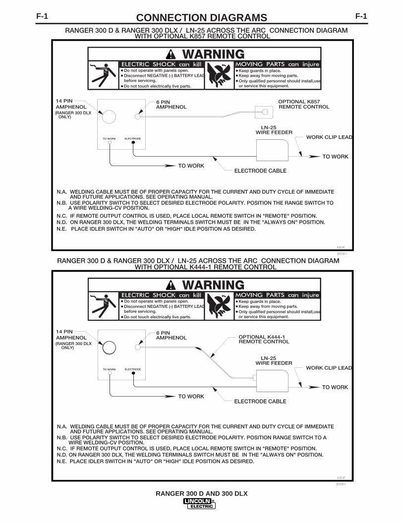
F-1CONNECTION DIAGRAMSF-1
RANGER 300 D AND 300 DLX
(RANGER 300 DLX ONLY)
6 PINAMPHENOL
TO WORK
14 PINAMPHENOL
LN-25
N.E. PLACE IDLER SWITCH IN "AUTO" OR "HIGH" IDLE POSITION AS DESIRED.
N.C. IF REMOTE OUTPUT CONTROL IS USED, PLACE LOCAL REMOTE SWITCH IN "REMOTE" POSITION.
6-20-97
S23732-1
ELECTRODE CABLE
WIRE FEEDER
TO WORK
WORK CLIP LEAD
OPTIONAL K857REMOTE CONTROL
N.A. WELDING CABLE MUST BE OF PROPER CAPACITY FOR THE CURRENT AND DUTY CYCLE OF IMMEDIATE AND FUTURE APPLICATIONS. SEE OPERATING MANUAL.
WARNING
or service this equipment.
Keep away from moving parts.Only qualified personnel should install,use
RANGER 300 D & RANGER 300 DLX / LN-25 ACROSS THE ARC CONNECTION DIAGRAMWITH OPTIONAL K857 REMOTE CONTROL
N.D. ON RANGER 300 DLX, THE WELDING TERMINALS SWITCH MUST BE IN THE "ALWAYS ON" POSITION.
N.B. USE POLARITY SWITCH TO SELECT DESIRED ELECTRODE POLARITY. POSITION THE RANGE SWITCH TO A WIRE WELDING-CV POSITION.
Do not operate with panels open.
before servicing.Disconnect NEGATIVE (-) BATTERY LEAD
Do not touch electrically live parts.
Keep guards in place.
ELECTRODETO WORK
S23732-2
RANGER 300 D & RANGER 300 DLX / LN-25 ACROSS THE ARC CONNECTION DIAGRAM
(RANGER 300 DLX ONLY)
N.C. IF REMOTE OUTPUT CONTROL IS USED, PLACE LOCAL REMOTE SWITCH IN "REMOTE" POSITION.
N.B. USE POLARITY SWITCH TO SELECT DESIRED ELECTRODE POLARITY. POSITION RANGE SWITCH TO A WIRE WELDING-CV POSITION.
N.A. WELDING CABLE MUST BE OF PROPER CAPACITY FOR THE CURRENT AND DUTY CYCLE OF IMMEDIATE AND FUTURE APPLICATIONS. SEE OPERATING MANUAL.
N.D. ON RANGER 300 DLX, THE WELDING TERMINALS SWITCH MUST BE IN THE "ALWAYS ON" POSITION.
6-20-97
ELECTRODE CABLE
WIRE FEEDER
OPTIONAL K444-1REMOTE CONTROL
TO WORK
WORK CLIP LEAD
Keep guards in place.
or service this equipment.
Keep away from moving parts.Only qualified personnel should install,use
WARNING
WITH OPTIONAL K444-1 REMOTE CONTROL
6 PINAMPHENOL
14 PINAMPHENOL
TO WORK
LN-25
Do not operate with panels open.Disconnect NEGATIVE (-) BATTERY LEADbefore servicing.Do not touch electrically live parts.
ELECTRODETO WORK
N.E. PLACE IDLER SWITCH IN "AUTO" OR "HIGH" IDLE POSITION AS DESIRED.
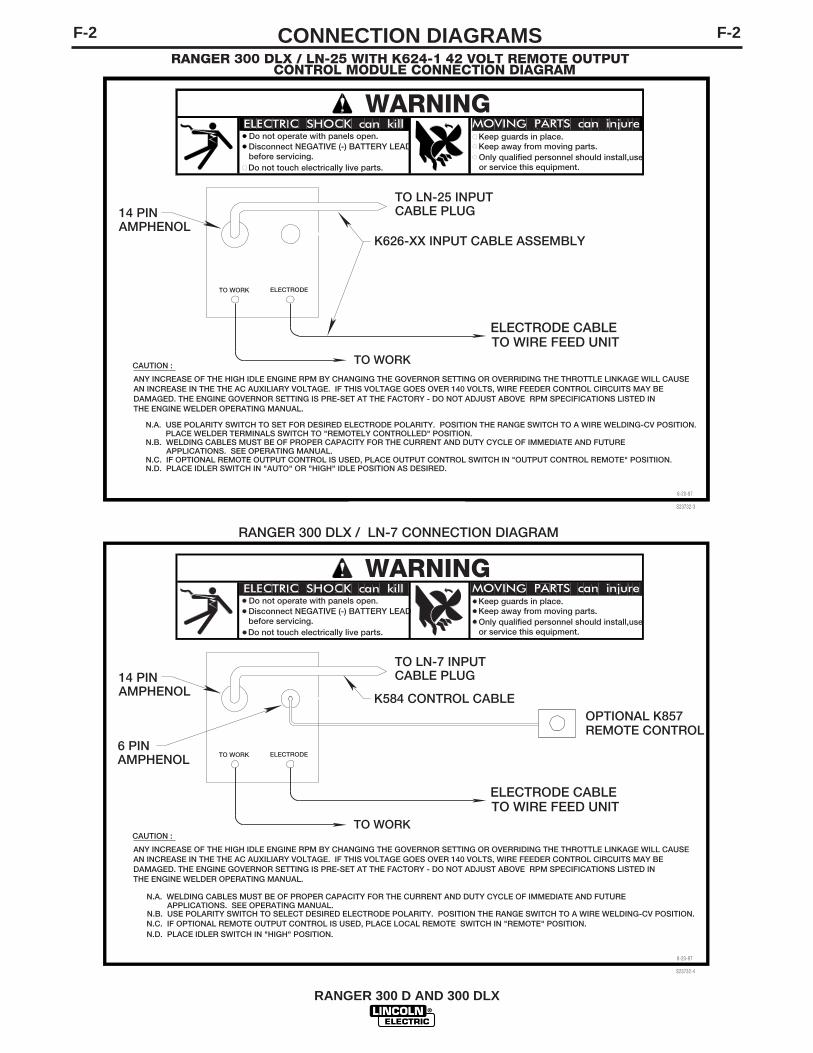
CONNECTION DIAGRAMS F-2F-2
RANGER 300 D AND 300 DLX
ELECTRODETO WORK
14 PIN
TO WORK
AMPHENOL
N.A. USE POLARITY SWITCH TO SET FOR DESIRED ELECTRODE POLARITY. POSITION THE RANGE SWITCH TO A WIRE WELDING-CV POSITION.
WARNINGKeep guards in place.
or service this equipment.
Keep away from moving parts.Only qualified personnel should install,use
CONTROL MODULE CONNECTION DIAGRAM RANGER 300 DLX / LN-25 WITH K624-1 42 VOLT REMOTE OUTPUT
N.B. WELDING CABLES MUST BE OF PROPER CAPACITY FOR THE CURRENT AND DUTY CYCLE OF IMMEDIATE AND FUTURE
6-20-97
Do not touch electrically live parts.
CABLE PLUG
CAUTION :
THE ENGINE WELDER OPERATING MANUAL.
PLACE WELDER TERMINALS SWITCH TO "REMOTELY CONTROLLED" POSITION.
APPLICATIONS. SEE OPERATING MANUAL.
N.D. PLACE IDLER SWITCH IN "AUTO" OR "HIGH" IDLE POSITION AS DESIRED.
AN INCREASE IN THE THE AC AUXILIARY VOLTAGE. IF THIS VOLTAGE GOES OVER 140 VOLTS, WIRE FEEDER CONTROL CIRCUITS MAY BEANY INCREASE OF THE HIGH IDLE ENGINE RPM BY CHANGING THE GOVERNOR SETTING OR OVERRIDING THE THROTTLE LINKAGE WILL CAUSE
DAMAGED. THE ENGINE GOVERNOR SETTING IS PRE-SET AT THE FACTORY - DO NOT ADJUST ABOVE RPM SPECIFICATIONS LISTED IN
N.C. IF OPTIONAL REMOTE OUTPUT CONTROL IS USED, PLACE OUTPUT CONTROL SWITCH IN "OUTPUT CONTROL REMOTE" POSITIION.
ELECTRODE CABLETO WIRE FEED UNIT
TO LN-25 INPUT
K626-XX INPUT CABLE ASSEMBLY
Do not operate with panels open.Disconnect NEGATIVE (-) BATTERY LEADbefore servicing.
S23732-3
WARNINGDo not operate with panels open.Disconnect NEGATIVE (-) BATTERY LEADbefore servicing.Do not touch electrically live parts.
ELECTRODETO WORK
S23732-4
CAUTION :
AN INCREASE IN THE THE AC AUXILIARY VOLTAGE. IF THIS VOLTAGE GOES OVER 140 VOLTS, WIRE FEEDER CONTROL CIRCUITS MAY BEANY INCREASE OF THE HIGH IDLE ENGINE RPM BY CHANGING THE GOVERNOR SETTING OR OVERRIDING THE THROTTLE LINKAGE WILL CAUSE
DAMAGED. THE ENGINE GOVERNOR SETTING IS PRE-SET AT THE FACTORY - DO NOT ADJUST ABOVE RPM SPECIFICATIONS LISTED INTHE ENGINE WELDER OPERATING MANUAL.
N.C. IF OPTIONAL REMOTE OUTPUT CONTROL IS USED, PLACE LOCAL REMOTE SWITCH IN "REMOTE" POSITION.
APPLICATIONS. SEE OPERATING MANUAL.
N.A. WELDING CABLES MUST BE OF PROPER CAPACITY FOR THE CURRENT AND DUTY CYCLE OF IMMEDIATE AND FUTURE
N.B. USE POLARITY SWITCH TO SELECT DESIRED ELECTRODE POLARITY. POSITION THE RANGE SWITCH TO A WIRE WELDING-CV POSITION.
N.D. PLACE IDLER SWITCH IN "HIGH" POSITION.
6-20-97
TO LN-7 INPUTCABLE PLUG14 PIN
AMPHENOL
OPTIONAL K857REMOTE CONTROL
6 PINAMPHENOL
ELECTRODE CABLE
TO WORK
TO WIRE FEED UNIT
Keep guards in place.Keep away from moving parts.Only qualified personnel should install,useor service this equipment.
K584 CONTROL CABLE
RANGER 300 DLX / LN-7 CONNECTION DIAGRAM

CONNECTION DIAGRAMS F-3F-3
RANGER 300 D AND 300 DLX
CAUTION :
or service this equipment.
Keep away from moving parts.Keep guards in place.
ELECTRODETO WORK
TO LN-742 INPUTCABLE PLUG14 PIN
K592 CONTROL CABLEAMPHENOL
ELECTRODE CABLE
TO WORK
TO WIRE FEED UNIT
N.E. PLACE IDLER SWITCH IN "AUTO" OR "HIGH" IDLE POSITION AS DESIRED.
6-20-97
S23732-5
RANGER 300 DLX / LN-742 CONNECTION DIAGRAM
THE ENGINE WELDER OPERATING MANUAL.
WARNINGDo not operate with panels open.Disconnect NEGATIVE (-) BATTERY LEADbefore servicing. Only qualified personnel should install,useDo not touch electrically live parts.
ANY INCREASE OF THE HIGH IDLE ENGINE RPM BY CHANGING THE GOVERNOR SETTING OR OVERRIDING THE THROTTLE LINKAGE WILL CAUSEAN INCREASE IN THE THE AC AUXILIARY VOLTAGE. IF THIS VOLTAGE GOES OVER 140 VOLTS, WIRE FEEDER CONTROL CIRCUITS MAY BEDAMAGED. THE ENGINE GOVERNOR SETTING IS PRE-SET AT THE FACTORY - DO NOT ADJUST ABOVE RPM SPECIFICATIONS LISTED IN
APPLICATIONS. SEE OPERATING MANUAL.N.A. WELDING CABLES MUST BE OF PROPER CAPACITY FOR THE CURRENT AND DUTY CYCLE OF IMMEDIATE AND FUTURE
N.C. PLACE WELDER TERMINALS SWITCH TO "REMOTELY CONTROLLED" POSITION. N.B. USE POLARITY SWITCH TO SET FOR DESIRED ELECTRODE POLARITY. POSITION THE RANGE SWITCH TO A WIRE WELDING-CV POSITION.
N.D. IF OPTIONAL REMOTE OUTPUT CONTROL IS USED, PLACE OUTPUT CONTROL SWITCH IN "OUTPUT CONTROL REMOTE" POSITIION.
Disconnect NEGATIVE (-) BATTERY LEAD
Do not touch electrically live parts.
14 PIN
AMPHENOL
TO WORK ELECTRODE
before servicing.
Do not operate with panels open.
TO WORKCAUTION :
THE ENGINE WELDER OPERATING MANUAL.
PLACE LOCAL / REMOTE SWITCH IN "REMOTE" POSITION.
APPLICATIONS. SEE OPERATING MANUAL.
N.C. PLACE IDLER SWITCH IN "HIGH" POSITION.
Keep guards in place.
S23732-6
Keep away from moving parts.
WARNING
Only qualified personnel should install,useor service this equipment.
TO LN-8 INPUT
K595 CONTROL CABLE
6-20-97
CABLE PLUG
RANGER 300 DLX / LN-8 CONNECTION DIAGRAM
ELECTRODE CABLETO WIRE FEED UNIT
N.A. WELDING CABLES MUST BE OF PROPER CAPACITY FOR THE CURRENT AND DUTY CYCLE OF IMMEDIATE AND FUTURE
AN INCREASE IN THE THE AC AUXILIARY VOLTAGE. IF THIS VOLTAGE GOES OVER 140 VOLTS, WIRE FEEDER CONTROL CIRCUITS MAY BEANY INCREASE OF THE HIGH IDLE ENGINE RPM BY CHANGING THE GOVERNOR SETTING OR OVERRIDING THE THROTTLE LINKAGE WILL CAUSE
DAMAGED. THE ENGINE GOVERNOR SETTING IS PRE-SET AT THE FACTORY - DO NOT ADJUST ABOVE RPM SPECIFICATIONS LISTED IN
N.B. USE POLARITY SWITCH TO SELECT DESIRED ELECTRODE POLARITY. POSITION THE RANGE SWITCH TO A WIRE WELDING-CV POSITION.

CONNECTION DIAGRAMS F-4F-4
RANGER 300 D AND 300 DLX
Keep away from moving parts.
31
NOT USED ON RANGER POWER SOURCES
42
TO WIRE FEED UNITELECTRODE CABLE
ADAPTER PLUGK867 UNIVERSAL
Only qualified personnel should install,use
82
41
81
Do not touch electrically live parts.
42
SPARE
6-20-97
S23732-7
CAUTION :
N.D. FOR WIRE FEEDERS THAT RETURN A SIGNAL FOR WELDING OUTPUT, USE ISOLATION
N.E. REFER TO POWER SOURCE INSTRUCTION MANUAL FOR MAXIMUM AUXILIARY CURRENT DRAW.
DAMAGED. THE ENGINE GOVERNOR SETTING IS PRE-SET AT THE FACTORY - DO NOT ADJUST ABOVE RPM SPECIFICATIONS LISTED INAN INCREASE IN THE THE AC AUXILIARY VOLTAGE. IF THIS VOLTAGE GOES OVER 140 VOLTS, WIRE FEEDER CONTROL CIRCUITS MAY BEANY INCREASE OF THE HIGH IDLE ENGINE RPM BY CHANGING THE GOVERNOR SETTING OR OVERRIDING THE THROTTLE LINKAGE WILL CAUSE
ELECTRODETO WORK
WARNING
THE ENGINE WELDER OPERATING MANUAL.
Do not operate with panels open.Disconnect NEGATIVE (-) BATTERY LEADbefore servicing.
N.B. USE POLARITY SWITCH TO SET DESIRED POLARITY, POSITION THE RANGE SWITCH TO A WIRE WELDING-CV POSITION.
Keep guards in place.
or service this equipment.
CONNECT TOGETHER FOR
WELDING OUTPUT
115 VACN.E.
TO2
4
N.A. WELDING CABLE MUST BE SIZED FOR CURRENT AND DUTY CYCLE OF APPLICATION.
RELAY TO CLOSE LEADS 2 & 4.
14 PIN
N.C. INSULATE EACH UNUSED LEAD INDIVIDUALLY.
TO WORK
AMPHENOL
RANGER 300 DLX TO K867 CONTROL CABLE ADAPTER CONNECTION DIAGRAM
K867
MIN.
WIRETO
FEEDER
N.D.
N.C.
REMOTE OUTPUT CONTROL10K
75
WIRE FEEDER VOLTMETER CONNECTION
76
POWER SOURCE FRAME CONNECTION
77CONNECTS TO (WORK TERMINAL) OF POWER SOURCE
42 VAC
21GND32
K488 SG
TO WORK
CONTROL MODULE
RECEPTACLE14 PIN WIRE FEEDER
RANGER
115V RECEPTACLE
THE ENGINE WELDER OPERATING MANUAL.
K487-25SPOOL GUN
BE SURE THAT CONTROL MODULE MODE SLIDE SWITCH IS IN THE "LINCOLN" (CONTACT CLOSURE) POSITION BEFORE ATTEMPTING TO OPERATECONTROL MODULE. INCORRECT SWITCH POSITION COULD RESULT IN DAMAGE TO THE CONTROL MODULE AND/OR POWER SOURCE.
before servicing.
ELECTRODE
RANGER 300 DLX / K691-10 / K488 / K487 SPOOL GUN CONNECTION DIAGRAM
Disconnect NEGATIVE (-) BATTERY LEAD
INPUT CABLEK691-10
or service this equipment.
N.A. WELDING CABLE MUST BE SIZED FOR CURRENT AND DUTY CYCLE OF APPLICATION.
PLACE WELDING TERMINALS SWITCH TO "REMOTELY CONTROLLED" POSITION.
ANY INCREASE OF THE HIGH IDLE ENGINE RPM BY CHANGING THE GOVERNOR SETTING OR OVERRIDING THE THROTTLE LINKAGE WILL CAUSEAN INCREASE IN THE THE AC AUXILIARY VOLTAGE. IF THIS VOLTAGE GOES OVER 140 VOLTS, WIRE FEEDER CONTROL CIRCUITS MAY BEDAMAGED. THE ENGINE GOVERNOR SETTING IS PRE-SET AT THE FACTORY - DO NOT ADJUST ABOVE RPM SPECIFICATIONS LISTED IN
Keep away from moving parts.Do not operate with panels open.
WARNINGKeep guards in place.
Only qualified personnel should install,useDo not touch electrically live parts.
N.C. IF OPTIONAL K857 REMOTE OUTPUT CONTROL IS CONNECTED TO 6 PIN RECEPTACLE,PLACE OUTPUT CONTROL SWITCH IN
N.B. USE POLARITY SWITCH TO SET FOR DESIRED ELECTRODE POLARITY. POSITION THE RANGE SWITCH TO A WIRE WELDING-CV POSITION.
"OUTPUT CONTROL REMOTE" POSITION.N.D. PLACE IDLER SWITCH IN "HIGH" IDLE POSITION.
6 PIN REMOTE
CAUTION :
S23732-8
TO CONTROL MODULEELECTRODE CABLE
RECEPTACLE
TO WORK
6-20-97

CONNECTION DIAGRAMS F-5F-5
RANGER 300 D AND 300 DLX
14 PINAMPHENOL
ELECTRODE
6-20-97
K963-1 HAND AMPTROL
-OR-
S23732-9
-OR-
K814 ARC START SWITCH
K870 FOOT AMPTROL
N.B. USE POLARITY SWITCH TO SELECT DESIRED ELECTRODE POLARITY. POSITION THE RANGE SWITCH TO A "STICK/WELD" POSITION.
DAMAGED. THE ENGINE GOVERNOR SETTING IS PRE-SET AT THE FACTORY - DO NOT ADJUST ABOVE RPM SPECIFICATIONS LISTED IN
AN INCREASE IN THE THE AC AUXILIARY VOLTAGE. IF THIS VOLTAGE GOES OVER 140 VOLTS, WIRE FEEDER CONTROL CIRCUITS MAY BEANY INCREASE OF THE HIGH IDLE ENGINE RPM BY CHANGING THE GOVERNOR SETTING OR OVERRIDING THE THROTTLE LINKAGE WILL CAUSE
THE ENGINE WELDER OPERATING MANUAL.
APPLICATIONS. SEE OPERATING MANUAL.
N.C. PLACE WELDER TERMINALS SWITCH TO " REMOTELY CONTROLLED" POSITION.
N.A. WELDING CABLES MUST BE OF PROPER CAPACITY FOR THE CURRENT AND DUTY CYCLE OF IMMEDIATE AND FUTURE
N.D. PLACE OUTPUT CONTROL SWITCH IN "REMOTE CONTROL" POSITION.N.E. PLACE IDLER SWITCH IN "AUTO" OR "HIGH" IDLE POSITION AS DESIRED.
FLOWMETER
CAUTION :
K936-1CONTROL CABLE
RANGER 300 DLX / K930-1 TIG MODULE / CONNECTION DIAGRAM
Keep guards in place.Keep away from moving parts.
WARNING
Only qualified personnel should install,useor service this equipment.
Do not operate with panels open.
Disconnect NEGATIVE (-) BATTERY LEADbefore servicing.
INPUT
REGULATOR
TO GAS
FITTING
Do not touch electrically live parts.
CYLINDER
ARGON GAS
TO WORK
ELECTRODE
-OR-
6 PINAMPHENOL
K814 ARC START SWITCH
S23732-10
K870 FOOT AMPTROL
-OR-K963-1 HAND AMPTROL
CRM after 9-23-97
CAUTION :
AN INCREASE IN THE THE AC AUXILIARY VOLTAGE. IF THIS VOLTAGE GOES OVER 140 VOLTS, WIRE FEEDER CONTROL CIRCUITS MAY BEANY INCREASE OF THE HIGH IDLE ENGINE RPM BY CHANGING THE GOVERNOR SETTING OR OVERRIDING THE THROTTLE LINKAGE WILL CAUSE
THE ENGINE WELDER OPERATING MANUAL.
APPLICATIONS. SEE OPERATING MANUAL.N.A. WELDING CABLES MUST BE OF PROPER CAPACITY FOR THE CURRENT AND DUTY CYCLE OF IMMEDIATE AND FUTURE
N.C. PLACE OUTPUT CONTROL SWITCH IN "REMOTE CONTROL" POSITION.
DAMAGED. THE ENGINE GOVERNOR SETTING IS PRE-SET AT THE FACTORY - DO NOT ADJUST ABOVE RPM SPECIFICATIONS LISTED IN
N.D. PLACE IDLER SWITCH IN "HIGH" IDLE POSITION.
N.B. USE POLARITY SWITCH TO SELECT DESIRED ELECTRODE POLARITY. POSITION THE RANGE SWITCH TO A "STICK/WELD" POSITION.
FLOWMETER
K963-3CONTROL CABLE
Keep guards in place.Keep away from moving parts.
WARNING
Only qualified personnel should install,useor service this equipment.
Do not operate with panels open.Disconnect NEGATIVE (-) BATTERY LEADbefore servicing.
INPUT
REGULATOR
TO GAS
FITTING
Do not touch electrically live parts.
CYLINDER
ARGON GAS
TO WORK
RANGER 300 D / K930-1 TIG MODULE WITH K938-1 CONTACTOR KIT / CONNECTION DIAGRAM

CONNECTION DIAGRAMS F-6F-6
RANGER 300 D AND 300 DLX
N.D.
CONNECT THE CONTROL CABLEGROUND LEAD TO THE FRAME
TO WORK
EXTENDED #21 LEAD SHOULD BE TAPED TO THE WELDING WORK LEAD.
N.G. TAPE UP BOLTED CONNECTION WHERE LEAD #21 IS EXTENDED.
N.E. WELDING CABLES MUST BE OF PROPER CAPACITY FOR THE CURRENT AND DUTY CYCLE OF IMMEDIATE AND FUTURE
FOR THE INSTALLATION. AN S16586-"LENGTH" REMOTE VOLTAGE SENSING WORK LEAD MAY BE ORDERED FOR THISN.F. IF LN-7 IS EQUIPPED WITH A METER KIT, EXTEND LEAD #21 USING #14 OR LARGER INSULATED WIRE PHYSICALLY SUITABLE
PURPOSE. CONNECT IT DIRECTLY TO THE WORK PIECE INDEPENDENT OF THE WELDING WORK CABLE. FOR CONVENIENCE, THIS
CAUTION: ANY SPEED UP OF THE ENGINE RPM BY CHANGING THE GOVERNOR SETTING OR OVERRIDING THETHROTTLE LINKAGE WILL CAUSE AN INCREASE IN THE AC AUXILIARY VOLTAGE. IF THIS VOLTAGE GOES ABOVE
FACTORY - DO NOT ADJUST ABOVE RPM SPECIFICATIONS LISTED IN ENGINE WELDER OPERATING MANUAL.140 VOLTS, THE LN-7 CONTROL CIRCUIT WILL BE DAMAGED. THE ENGINE GOVERNOR SETTING IS PRE-SET AT THE
NOTE: PLACE OUTPUT CONTROL SWITCH IN "OUTPUT CONTROL REMOTE" POSITION WHEN REMOTE OUTPUT CONTROL IS USED.
ELECTRODEWORK
POWERSOURCE
APPLICATIONS. (SEE OPERATOR’S MANUAL.)
OF 500 VOLT AMPERES.
N.D. LEADS #21 AND GND. DO NOT APPEAR ON LN-7’S WITH CODES BELOW 7026.
N.C. PLUG INTO 115 VOLT AC RECEPTACLE ON WELDER CONTROL PANEL OR OTHER 115 VOLT AC SUPPLY RATED AT A MINIMUM
N.B. 3 CONDUCTOR #16 POWER CORD PHYSICALLY SUITABLE FOR THE INSTALLATION AND PLUG RATED AT 115 VOLTS 15 AMPERES AC.
SWITCH ON THE POWER SOURCE TO THE CV POSITION.N.A. USE POWER SOURCE POLARITY SWITCH TO SET FOR DESIRED ELECTRODE POLARITY. POSITION THE OUTPUT SELECTOR
WELDER STANDARD OUTPUT TERMINALS
AN UNPAINTED FRAME SCREW.
CONTROL CABLE
THE TERMINAL STRIP OR TO TERMINAL MARKED
RANGER 300 D / LN-7 / K240 CONTACTOR KIT
Keep away from moving parts.
N.B.
Only qualified personnel should install,use
WARNING
21
Do not touch electrically live parts.before servicing.Disconnect NEGATIVE (-) BATTERY LEADDo not operate with panels open.
EQUIP.
N.H. IDLER SWITCH ON POWER SOURCE MUST BE IN HIGH IDLE POSITION.
K240 CONTACTOR KIT
N.J.
ELECTRODE CABLE TO LN-7
NEAR
N.F. & N.G.
6 PIN AMPHENOL
N.J. IF AN OPTIONAL K857 REMOTE OUTPUT CONTROL IS USED, CONNECT IT TO THE RANGER 300 D AMPHENOL CONNECTOR.
(NOTE : 600 AMP CAPACITY)
S23732-11
GND.
AUTO.
32
32
2
2
4
4
31
POWERSOURCE
31
N.C.
Keep guards in place.
or service this equipment.
115V (50/60HZ.)
TO LN-7
6-20-97

F-7WIRING DIAGRAMF-7
RANGER 300 D AND 300 DLX
5A
221
INDI
CATE
S JA
CK N
UMBE
R
51
CAP
ACIT
OR
S
236A
OU
TPU
T4
REC
TIFI
ER
5A
_
C2
(-)
A2
+24
5
DC
+
232
R4
R3
W7
224 22
4C
C1
3B
WHITE
3F
11
3A
15A
BLA
CK
BLACK
12BL
ACK
BLACK
WHITE
120/
240V
J8
BLACK
BLACKBLACK
BLACK
BLAC
K
BLACK
CB7
3D
(15A
MP)
SWIT
CH
A121
0W
14
S2A
(CLO
SED
POSI
TIO
N)
219
32
GN
D-C
9
10J1
0
SWIT
CH
9J10
221B
OIL
PRES
SURE
SWIT
CH 222D
5K
COIL
J11
ALT
ERNA
T0R
CON
NECT
ION
BLO
CK(H
ARNE
SS L
EAD
END)
FUE
L SH
UTDO
WN
SOL
ENOI
D(H
ARNE
SS L
EAD
END)
IDLE
R SO
LENO
ID(H
ARNE
SS L
EAD
END)
224A
5K
222F
222G
+
5H
226 CR
ANK
MOT
OR
"SIG
" TER
MIN
AL
5K
SOLE
NOID
J12
(-)
201
NO
TE
S:
RED
C4
(+)
R2
J4 J775A
48
W9
76A
76B
COIL
5G
5J10
ON S7
WAT
ER
222
221C
CONT
ROL
SWIT
CHSH
OWN
IN
WEL
DING
TER
MIN
AL
214B
"ALW
AYS
ON"
224E
POSI
TION
OIL
BLUE
224H
77
236
239
232
8J10
227A
FUEL
235B
235C
224G
CB9
15A
R
11J1
0
222C
221A
6J10
7J10
213B
254B
FBA
CO
NTA
CTO
R2
4B77B
AC
OU
TPU
TC
ON
TAC
TOR
VM
3H
WHITE
WHI
TE
3G
15A
CB5
3C
BLAC
K
GND-
G TERM
.CO
LORE
DSI
LVER
GREEN
BLACK
3D
5L
J9 120
V
120
VBLACK
3A
3E
5D
BLAC
K
3B
CB4
11
5
15A
5
15A
5L
5D
J10
REM
OTE
CO
NTR
OL
200A
MAX
(SH
OW
N IN
REM
OTE
SW
ITC
H
REM
OTE
PO
SITI
ON
)
CB6
A1
7REA
CTO
R
W12
W16
C1C2
125/
250V
. SIN
GLE
77A
6
31A
(-)
5B 5H
254B
3
W11
DC
-
CR1
C3
C4
R3
5A
C3
75A
76D
GAUG
E
GN
D-E
5
BYPA
SS P
C4
67
4C
5E
77B
2A
5
77C
76C
4A
50A
J5
75C
77A
F
REM
OTE
CO
NTR
OL
G
42VA
C
2C
PCB2
J6
1 3
3
GND-
D
1
2C 77A
67 21A
5E 5A
AC
(+)
214
TERM
INAL
SCO
LORE
DSI
LVER
GREEN
GND-
C
50A
CB2
6
BLACK
227
J13
CU
RR
ENT
SEN
SOR
224
W3
1
75
3
4
201A
J1
OU
TPU
TR
HEO
STAT
S8
CW
7510
K P
OT
76
GN
D-E
76D
GN
D-D
201A AC
7
(+)
RED
RED
200B
21
31A
32 4AC
ON
TAC
TOR
2AC
21H
WO
RK
77C
76C
75C
31B
I42
K
GN
D-A
GR
OU
ND
STAR
TS4
223A
222 "O
N" P
OSIT
ION
225
223
222B
GLOW
PLU
G
222B
222A 225
STAR
TER
224B
1J10
HOLD
L3 FUEL
5H
227
ALTE
RNAT
OR
254
254A
J2
610
5
200
201
C5
240
31
IDLE
R
S6ON
/OFF
IDLE
R A
C
J12
237
224B
W4
L
1026
2
PCB
1 7 3
R
CHAR
GER
5F
220
6-
20-9
7
W13
C2
SWIT
CH
W1
C3
2C
232
77A
W5
224C
GROU
ND S
CREW
BLOW
ER B
AFFL
E
W4
5E
SLI
PR
ING
S
(-)
220
221
E
GR
OU
ND
AM
PHEN
OL
2
247
SOLE
NOID
SPEE
DHI
GH
HOLD
76B
75B
4B
J10
1J10 IN
DICA
TES
CAVI
TY N
UMBE
R
800
MFD
GREEN
RECE
PTAC
LE
SILV
ER
3C
GN
D-G
6
W7
50W
240
241
R W2
35A
76A
CB
1
42
213
W6
ELEC
TRO
DE
POLA
RIT
Y
240
25W
W15
WIT
H S
2 IN
236
WO
RK
C476
A
(-)12
VOL
T
IGBCO
IL
BLAC
KSH
UTDO
WN
L
237
PULL
SOLE
NOID
CONT
ACTO
RST
ARTE
R
J13
WIR
ING
DIA
GR
AM
- R
AN
GE
R 3
00 D
LX
222
6
3 TU
RN
S
254C
IDLE
R W
ELD
CU
RR
ENT
L1(C
HO
KE)
210
247
250
SWIT
CH
213
235
2
3
(+)
R1
224C
FUEL
HOUR
MET
ER
5W
235
AUTO
235B
BATT
ERY
BLUE
SWIT
CH
5G
FLASHING CURRENT
77
2J10
5C
COLO
RED
TERM
INAL
S
CB3
3
A2
D2B GN
D-B
R2
COIL
CV+
100
254
C
31,0
00 M
FD
W3
239
D1
STAT
OR
9
254A
ELEC
TROD
E
AM
PHEN
OL
1
J
6
76A
4
E
(-)
(+)RED
214
201A
214
224
76
77200B
D2
77D
S1
CV-
W8
W10
4C
W1
1
25 O
HM
SEN
DER
+
S5
235A
12J1
0
ENGI
NE
220A
POSI
TION
224D
-
J11
3J10
GLOW
PLU
GS
224F
5F
L2
CB8
15A
BLAC
K
222J
222F 22
2K
2C
SWIT
CH
SHOW
N IN
"HIG
H"
S3
HIGH
222G
5C
8
J3
1
200B
1211
109
85 1
24
ENGI
NE H
ARNE
SS C
ONNE
CTOR
TO P
ANEL
HAR
NESS
TEM
P.W
ATER
222E
RED
PULL
COIL
222E
222H
WHI
TE
BLAC
K
224F
S
5B
BLACK
4J10
214A
213A
222D 22
4A
250
FRAM
EGR
OUND
220C
(+)
SWIT
CH
224E
ENGI
NEGR
OUND
R 220B
BATT
ERY
TEM
P.PR
ESSU
RE
WHI
TERE
D
SHOW
N IN
PCB
OAR
DSE
NSO
R
211
C1,
C2,
C3
OR
C4
C1
R6 R
7R
5
219
R1
RAN
GE
W12
S2
(+)
RED
RO
TOR
FIE
LD
PO
SIT
IVE
SLI
PR
ING
NEA
RES
TLA
MIN
ATI
ON
B
GR
OU
ND
SC
REW
ABO
VE A
MPH
ENO
L H
OLE
EL
EC
TR
ICA
L S
YM
BO
LS
PE
R E
1537
AL
L C
AS
E F
RO
NT
CO
MP
ON
EN
TS
VIE
WE
D F
RO
M R
EA
R.75
A
W9
W10
GN
D
21A
A11
5VAC
D
75B
2B
NO
TE
: T
his
dia
gra
m is
fo
r re
fere
nce
onl
y.
It m
ay n
ot
be
accu
rate
fo
r al
l mac
hine
s co
vere
d b
y th
is m
anua
l. T
he s
pec
ific
dia
gra
m f
or
a p
artic
ular
co
de
is p
aste
d in
sid
eth
e m
achi
ne o
n o
ne o
f th
e en
clo
sure
pan
els.
If
the
dia
gra
m is
ille
gib
le, w
rite
to
the
Ser
vice
Dep
artm
ent
for
a re
pla
cem
ent.
Giv
e th
e eq
uip
men
t co
de
num
ber
..

F-8WIRING DIAGRAMF-8
RANGER 300 D AND 300 DLX
67
75A
3C
PCB2
BYPA
SS P
C 41
76B
2
J10
227
76A
5E
4
BLACK
BLACK
11
RECE
PTAC
LE
3B
125/
250V
. SIN
GLE
BLA
CK
BLAC
K
BLACK
BLAC
K
3F
3A3B
201
B
1J10
2J10
222B
225
223
3J10
HIGH
GLOW
PLU
G
GLOW
PLU
GS
FLASHING CURRENT
5AC
9
15A
50A
77B
201
CB2
75B
3
CB7
15A
J10
5
W4
254
TERM
INAL
S
5L
GREEN
GND-
C
5H
ENGI
NEGR
OUND
5H
PULL
HOLD
L3 FUEL
IG L
ALTE
RNAT
OR
INDI
CATE
S JA
CK N
UMBE
R
1J10 IN
DICA
TES
CAVI
TY N
UMBE
R
GREEN
75A
R3M
AX10
K P
OT
75
CW
76D
77R
HEO
STAT
RED
J3
214
200B
219
224
A1
R1
W12
R
ENGI
NE H
ARNE
SS C
ONNE
CTOR
TO P
ANEL
HAR
NESS
GN
D
5E
15A
5K
222G
214
240
221
BO
ARD
PCB
1
254B
254A 25
4
224D
222
213B
5F
214B
15A
77
BATT
ERY
214A
213A
227A
SWIT
CH
SHOW
N IN
"HIG
H"PO
SITI
ON
AUTO
235
224F
5F
250
222D
3G
GND-
G J8 120/
240V
CB5
15A
3C
BLACK
12
76A
3A77
A
76B
75B
GN
D-B
5F
J11
J7
5D75
A
BLACK
FUE
L SH
UTDO
WN
SOL
ENOI
D(H
ARNE
SS L
EAD
END)
GR
OU
ND
SC
REW
IDLE
R SO
LENO
ID(H
ARNE
SS L
EAD
END)
ABO
VE A
MPH
ENO
L H
OLE
3HGN
D-G
5A
WHITE
WHITE
WHI
TE
COLO
RED
TERM
.
SILV
ER
WHITE
BLACK
BLACK
ALT
ERNA
T0R
CON
NECT
ION
BLO
CK(H
ARNE
SS L
EAD
END)
224A
222F
213
(+)
239
W15
W1
200A
OU
TPU
T
D2
RO
TOR
FIE
LD
(+) (-)
BLACK
BLAC
K
CB6
5D5L
J9
ELEC
TROD
E
3E
J13
J12
227
224B23
7
WO
RK
DC
+S1
SWIT
CH
7576
5W
GAUG
E226
SEN
DER
"SIG
" TER
MIN
AL
224E
+
240
222
224
CHAR
GER
SEN
SOR
254C
IDLE
R W
ELD
CU
RR
ENT
COIL
COIL
PULL RE
D
L2
WHI
TE
-
BLACK
J11
RTE
MP.
WAT
ER
220B
221C
12 V
OLT
BATT
ERY
+
222E
220C
TEM
P.W
ATER
OIL
224E
224
S
CRAN
KM
OTOR
WHI
TE
COIL
COIL
SOLE
NOID
5E
67 21A
NO
TE
S:
EL
EC
TR
ICA
L S
YM
BO
LS
PE
R E
1537
AL
L C
AS
E F
RO
NT
CO
MP
ON
EN
TS
VIE
WE
D F
RO
M R
EA
R.
GROU
NDJ1
2FR
AME
(-)
BLAC
KJ1
3SH
UTDO
WN
220A235B
CONT
ACTO
R
237
5K
5K
REM
OTE
SW
ITC
H
L1(C
HO
KE)
W6
224G R
224H
5G
221A
225
R
6J10
STAR
TER
SOLE
NOID
COIL
S5
SWIT
CH
IDLE
R
224B
222
RED
S4
S3
STAR
T
222G
222G
SWIT
CH
223A
ON/O
FFS6
5B
PRES
SURE
235A
222C
FUEL
8J10
FUEL
9J10
235C
235B
BLUE
221B
CB9
(+)
222D
11J1
0220
222B
BLUE
STAR
TER
ELEC
TRO
DE
POLA
RIT
Y
77B
REM
OTE
CO
NTR
OL
AC
DC
- AC
DC
-
DC
+
OU
TPU
T
D1
W11
REC
TIFI
ER
R2
W16
50 W
25 O
HM
77A
1
R3
3
SWIT
CH
C1
5
77D
S876
3D
3D
PC
CB8
15A
BLAC
KBL
ACK
222E
222F
222J
222K
222H
HIGH
HOLD
SPEE
DSO
LENO
ID
5G 224F
ENGI
NEHO
UR M
ETER
5H
SEN
SOR
CU
RR
ENT
IDLE
R A
C
(-)
5
200B
7
201A
W7
5M
5M
W10
213
RED
BLACK
GN
D-D
200 R
ED
6
PO
SIT
IVE
SLI
PR
ING
NEA
RES
TLA
MIN
ATI
ON
3
GN
D-E
BLAC
K
J5
201A
120
V
11
BLACK
R2
12J1
0
10
5
84
5A
2J1
214
1
A2R
EAC
TOR
C1
221
241
A1W
12
236
(-)
7J10
SWIT
CH
OIL
PRES
SURE
SWIT
CH
"ON"
POS
ITIO
N
10J1
0
SHOW
N IN
SWIT
CH
222A
236
239
5J10
4J10
67 3
224A
1211
109
85 1
24
219 (-
) RIN
GS
(+)
5A
BLOW
ER B
AFFL
E
C1
CB4
800
MFD
(SH
OW
N IN
REM
OTE
PO
SITI
ON
)7
A
GN
D-E
STAT
OR
SILV
ERCO
LORE
D
C
GR
OU
ND
AM
PHEN
OL
R6
R4
R7
R5
RAN
GE
S2
76A
W1
76D
77A
96
GROU
ND S
CREW
3
WIR
ING
DIA
GR
AM
- R
AN
GE
R 3
00 D
GN
D-C
CB3
50A
254A
W10
L
1055
6
9-
12-9
7A
77
6
3
TERM
INAL
S
B
77A
76A
3J6
F
W2
21A
GREEN
120
V
SILV
ERCO
LORE
D
5B
(+)
SLI
P
(+)
RED
ACGN
D-D
6
3 TU
RN
S
W7
W11
J2
250
16
220
200B
W4
420
1A23
525
4B
A21
W9
3
NO
TE
: T
his
dia
gra
m is
fo
r re
fere
nce
onl
y.
It m
ay n
ot
be
accu
rate
fo
r al
l mac
hine
s co
vere
d b
y th
is m
anua
l. T
he s
pec
ific
dia
gra
m f
or
a p
artic
ular
co
de
is p
aste
d in
sid
eth
e m
achi
ne o
n o
ne o
f th
e en
clo
sure
pan
els.
If
the
dia
gra
m is
ille
gib
le, w
rite
to
the
Ser
vice
Dep
artm
ent
for
a re
pla
cem
ent.
Giv
e th
e eq
uip
men
t co
de
num
ber
..

F-9WIRING DIAGRAMF-9
RANGER 300 D AND 300 DLX
NO
TE
: T
his
dia
gra
m is
fo
r re
fere
nce
onl
y.
It m
ay n
ot
be
accu
rate
fo
r al
l mac
hine
s co
vere
d b
y th
is m
anua
l. T
he s
pec
ific
dia
gra
m f
or
a p
artic
ular
co
de
is p
aste
d in
sid
eth
e m
achi
ne o
n o
ne o
f th
e en
clo
sure
pan
els.
If
the
dia
gra
m is
ille
gib
le, w
rite
to
the
Ser
vice
Dep
artm
ent
for
a re
pla
cem
ent.
Giv
e th
e eq
uip
men
t co
de
num
ber
..
5A
221
INDICATE
S JACK NUM
BER
51
CAPACITORS
236A
W
OUTPUT
4RECTIFIER
5A
_
C2
(-)
A2
+245
DC+
232
R4
R3
W7
224 224C
C1
3B
WHITE
3F
11
3A
15A
BLACK
BLACK
12BL
ACK
BLACK
WHITE
120/240V
J8
BLACK
A
BLACKBLACK
BLACK
BLAC
K
BLACK
CB7
3D
(15AMP)
SWITCH
A1
210
W14
S2A (CLOSED
POSITION)
219
32
GND-C 9
10J10
SWITCH
9J10
221B
OIL PRESS
URE
SWITCH
222D
5K
COIL
J11
ALTERNAT0R
CON
NECTION
BLOCK
(HAR
NESS LEA
D END)
FUEL SHUT
DOW
N
SOLENOID
(HAR
NESS LEA
D END)
IDLE
R SO
LENOID
(HAR
NESS LEA
D END)
224A
5K
222F
222G
+
5H
226 C
RANK
MOTOR
"SIG" TERMIN
AL
5K
SOLE
NOID
J12
(-)
201
NOTES:
RED
C4
(+)
R2
J4
J7
75A
48
W9
76A
76B
COIL
5G
5J10
ON S7
WATER
222
221C
CONT
ROL SWITCH
SHOWN IN
WELDING TE
RMINA
L
214B
"ALW
AYS ON"
224E
POSITION
OIL
BLUE
224H
77
236
239
232
8J10
227A
FUEL
235B
235C
224G
CB9
15A
R
11J10
222C
221A
6J10
7J10
213B
254B
A
FBA
CONTACTOR
2
4B
77B
AC
OUTPUT
CONTACTOR
VM
3H
WHITE
WHITE
3G
15A
CB5
3C
BLAC
K
GND-G TE
RM.
COLO
RED
SILV
ER
GREEN
BLACK
3D
5L
J9
120 V
120 V
BLACK
3A
3E
5D
BLAC
K
3B
CB4
11
5
15A
5
15A
5L
5D
J10
REMOTE CONTROL
200A
MAX
(SHOWN IN
REMOTE SWITCH
REMOTE POSITION)
CB6
A1
7REACTOR
W12
W16
C1C2
125/250V
.SINGLE
77A
6
31A
(-)
5B
5H
254B
3
W11
DC-
CR1
C3
C4
R3
5A
C3
75A
76D
GAUG
E
GND-E
5
BYPA
SS PC
4
67
4C
5E
77B
2A
5
77C
76C
4A
50A
J5
75C
77A
F
REMOTE CONTROL
G
42VAC
2C
PCB2
J6
1 3
3
GND-D
1
2C
77A
6721A
5E
5A
AC
(+)
214
TERMINAL
SCOLO
RED
SILV
ER
GREEN
GND-C
50A
CB2
6
BLACK
227
J13
CURRENT
SENSOR
224
W3
1
75
3
4
201A
J1
OUTPUT
RHEOSTAT
S8
CW
75
10K POT
76
GND-E
76D
GND-D
201A
AC
7
(+)
RED
RED
200B
21
31A
32 4A
CONTACTOR
2A
C
21
HWORK
77C
76C
75C
31B
I
42
K
GND-A
GROUND
START
S4
223A
222 "O
N" POSITION
225
223
222B
GLOW P
LUG
222B
222A
225
STARTE
R224B
1J10
HOLD
L3 FUEL
5H
227
ALTE
RNATO
R
254
254A
J2
610
5
200
201
C5
240
31
IDLE
R
S6
ON/OFF
IDLER AC
J12
237
224B
W4
PCB1 7 3
R
CHA
RGER
5F
220
2/20
01B
L117
02
W13
C2
SWITCH
W1
C3
2C
232
77A
W5
224C
GROUND SCREW
BLOWER
BAF
FLE
W4
5E
(-)
220
221
E
GROUND
AMPHENOL 2
247
SOLE
NOID
SPEE
DHIGH
HOLD
76B
75B
4B
J10
1J10 A
A
INDICATE
S CAVITY NUM
BER
800 MFD
GREEN
REC
EPTA
CLE
SILV
ER
3C
GND-G
6
W7
50W
240
241
R W2
35A
76A
CB1
42
213
W6
ELECTRODE POLARITY
240
25W
W15
WITH S2 IN
236
WORK
C476A
(-)
12 VOLT
IGBCOIL
BLAC
KSH
UTDOW
NL
237
PULL
SOLE
NOID
CONTACTOR
STARTE
R
J13
WIRING DIAGRA
M - RA
NGE
R 300DLX
222
6
3 TURNS
A A
254C
A
IDLER WELD
CURRENT
L1
(CHOKE)
210
247
250
SWITCH
213
235
2
3
(+)
R1
224C
FUEL
HOUR METE
R
5W
235
AUTO
235B
BATTERY
BLUE
SWITCH
5G
FLASHING CURRENT
77
2J10
5C
COLO
RED
TERMINAL
S
CB3
3
A2
A
D2B
GND-B
R2
COIL
CV+
100
254
C
31,000 MFD
W3
239
D1
STATOR
9
254A
ELEC
TROD
E
AMPHENOL 1
J
6
76A
4
E
(-)
(+)
RED
214
201A
214
224
76
77
200B
D2
77D
S1
CV-
W8
W10
4C
W1
1
25OHM
SENDE
R
+
S5
235A
12J10
ENGINE
220A
POSITION
224D
-
J11
3J10
GLOW P
LUGS
224F
5F
L2
CB8
25A
BLAC
K
222J
222F
222K
2C
SWITCH
SHOWN IN
"HIGH"
S3
HIGH
222G
5C
8
J3
1
200B
12
11
10
9
85 1
24
ENGINE HARNE
SS CON
NECTOR
TO PAN
EL HARNE
SS
TEMP.
WATER
222E
RED
PULL
COIL
222E
222H
WHITE
BLAC
K
224F
S
5B
4J10
214A
213A
222D 224A
250
FRAME
GROUND
220C
(+)
SWITCH
224E
ENGINE
GROUND
R
220B
BATTERY
TEMP.
PRESSURE
WHITE
RED
SHOWN IN
PC
BOARD
SENSOR
211
C1,C2,C3 OR C4
C1
R6R7
R5
219
R1
RANGE
W12
S2
(+)
RED ROTOR FIELD
POSITIVE SLIP
RING NEAREST
LAMINATION
B
GROUND SCREW
ABOVE AMPHENOL HOLE
ELECTRICAL SYMBOLS PER E1537
ALL CASE FRONT COMPONENTS VIEWED FROM REAR.
75A
W9
W10
GND
21A
A115VAC
D
75B
2B
CR
222W
214Z
213Y
222X
213X
5Z21
3Z
222Z
SLIP
RINGS

F-10DIMENSION PRINTF-10
RANGER 300 D AND 300 DLX
30.5
0
6-20
-97
13.0
0
33.8
1
60.1
8
13.8
5
18.4
8
6.75
34.8
6
20.2
5
12.3
6
60.5
0
17.3
7
18.0
0
11.9
8
6.26
M18
399
L
18.0
0
31.0
0
46.0
8C
RA
DIA
TOR
C
AP
CEN
TER
OF
GR
AVI
TY
.24
2.70
9.96
24.0
4
24.7
5
DIM
EN
SIO
N P
RIN
T -
RA
NG
ER
300

NOTES
RANGER 300 D AND 300 DLX

NOTES
RANGER 300 D AND 300 DLX

Now Available...12th EditionThe Procedure Handbook of Arc Welding
With over 500,000 copies of previous editions publishedsince 1933, the Procedure Handbook is considered by many to be the “Bible” of the arc welding industry.
This printing wil l go fast so don ’t delay. Place your order now using the coupon below.
The hardbound book contains over 750 pages of weldinginformation, techniques and procedures. Much of this material has never been included in any other book.
A must for al l welders, supervisors, engineers anddesigners. Many welding instructors will want to use the bookas a reference for all students by taking advantage of the lowquantity discount prices which include shipping by4th class parcel post.
$15.00 postage paid U.S.A. Mainland
How To Read Shop Drawings
The book contains the latest information and applicationdata on the American Welding Society Standard WeldingSymbols. Detailed discussion tells how engineers anddraftsmen use the “short-cut” language of symbols to passon assembly and welding information to shop personnel.
Practical exercises and examples develop the reader’s abilityto visualize mechanically drawn objects as they will appearin their assembled form.
187 pages with more than 100 illustrations. Size 8-1/2” x 11”Durable, cloth-covered board binding.
$4.50 postage paid U.S.A. Mainland
New Lessons in Arc WeldingLessons, simply written, cover manipulatory techniques;
machine and electrode characteristics; related subjects,such as distortion; and supplemental information on arcwelding applications, speeds and costs. Practice materials,exercises, questions and answers are suggested for each lesson.
528 pages, well illustrated, 6” x 9” size, bound in simulated,gold embossed leather.
$5.00 postage paid U.S.A. Mainland
Need Welding Training?The Lincoln Electric Company operates the oldest and
most respected Arc Welding School in the United States at itscorporate headquarters in Cleveland, Ohio. Over 100,000 stu-dents have graduated. Tuit ion is low and the training is “hands on”
For details write: Lincoln Welding School22801 St. Clair Ave. Cleveland, Ohio 44117-1199.
and ask for bulletin ED-80 or call 216-383-2259 and ask for theWelding School Registrar.
Lincoln Welding SchoolBASIC COURSE $700.00
5 weeks of fundamentalsThere is a 10% discount on all orders of $50.00 or more for shipment at one time to one location.Orders of $50 or less before discount or orders outside of North America must be prepaid with charge, check or money order in U.S. Funds Only.Prices include shipment by 4 thClass Book Rate for U.S.A. Mainland Only. Please allow up to 4 weeks for delivery.UPS Shipping for North America Only. All prepaid orders that request UPS shipment please add:
$5.00 For order value up to $49.99$10.00 For order value between $50.00 & $99.99$15.00 For order value between $100.00 & $149.00
For North America invoiced orders over $50.00 & credit card orders, if UPS is requested, it will be invoiced or charged to you at cost.Outside U.S.A. Mainland order must be prepaid in U.S. Funds. Please add $2.00 per book for surface mail or $15.00 per book for air parcel post shipment.METHOD OF PAYMENT: (Sorry, No C.O.D. Orders)
CHECK ONE:Name: _______________________________________________
Please Invoice (only if order is over $50.00)Address: _______________________________________________
Check or Money Order Enclosed, U.S. Funds only _______________________________________________
Credit Card - Telephone: _______________________________________________
Signature as it appears on Charge Card:Account No. |_|_|_|_|_|_|_|_|_|_|_|_|_|_|_|_|_|_|_|_|_| Exp Date |_|_| |_|_| ______________________Month Year
USE THIS FORM TO ORDER: Order from: BOOK DIVISION, The Lincoln Electric Company, 22801 St. Clair Avenue, Cleveland, Ohio 44117-1199BOOKS OR FREE INFORMATIVE CATALOGS Telephone: 216-383-2211 or, for fastest service, FAX this completed form to: 216-361-5901.
Lincoln Welding School Titles: Price Code Quantity Cost(ED-80) New Lessons in Arc Welding $5.00 L
Seminar Information Procedure Handbook “Twelfth Edition” $15.00 PH(ED-45) How to Read Shop Drawings $4.50 H
Educational Video Information Incentive Management $5.00 IM(ED-93) A New Approach to Industrial Economics $5.00 NA
James F. Lincoln Arc Welding The American Century of John C. Lincoln $5.00 ACFoundation Book Information Welding Preheat Calculator $3.00 WC-8
(JFLF-515) Pipe Welding Charts $4.50 ED-89SUB TOTAL
Additional Shipping Costs if anyTOTAL COST
MasterCard
VISA ®
AMERICAN EXPRESS
MasterCardMasterCard®
AMERICAN EXPRESS

WARNING
AVISO DEPRECAUCION
ATTENTION
WARNUNG
ATENÇÃO
Spanish
French
German
Portuguese
Japanese
Chinese
Korean
Arabic
READ AND UNDERSTAND THE MANUFACTURER’S INSTRUCTION FOR THIS EQUIPMENT AND THE CONSUMABLES TO BEUSED AND FOLLOW YOUR EMPLOYER’S SAFETY PRACTICES.
SE RECOMIENDA LEER Y ENTENDER LAS INSTRUCCIONES DEL FABRICANTE PARA EL USO DE ESTE EQUIPO Y LOSCONSUMIBLES QUE VA A UTILIZAR, SIGA LAS MEDIDAS DE SEGURIDAD DE SU SUPERVISOR.
LISEZ ET COMPRENEZ LES INSTRUCTIONS DU FABRICANT EN CE QUI REGARDE CET EQUIPMENT ET LES PRODUITS AETRE EMPLOYES ET SUIVEZ LES PROCEDURES DE SECURITE DE VOTRE EMPLOYEUR.
LESEN SIE UND BEFOLGEN SIE DIE BETRIEBSANLEITUNG DER ANLAGE UND DEN ELEKTRODENEINSATZ DES HER-STELLERS. DIE UNFALLVERHÜTUNGSVORSCHRIFTEN DES ARBEITGEBERS SIND EBENFALLS ZU BEACHTEN.
● Do not touch electrically live parts orelectrode with skin or wet clothing.
● Insulate yourself from work andground.
● No toque las partes o los electrodosbajo carga con la piel o ropa moja-da.
● Aislese del trabajo y de la tierra.
● Ne laissez ni la peau ni des vête-ments mouillés entrer en contactavec des pièces sous tension.
● Isolez-vous du travail et de la terre.
● Berühren Sie keine stromführendenTeile oder Elektroden mit IhremKörper oder feuchter Kleidung!
● Isolieren Sie sich von denElektroden und dem Erdboden!
● Não toque partes elétricas e elec-trodos com a pele ou roupa molha-da.
● Isole-se da peça e terra.
● Keep flammable materials away.
● Mantenga el material combustiblefuera del área de trabajo.
● Gardez à l’écart de tout matérielinflammable.
● Entfernen Sie brennbarres Material!
● Mantenha inflamáveis bem guarda-dos.
● Wear eye, ear and body protection.
● Protéjase los ojos, los oídos y elcuerpo.
● Protégez vos yeux, vos oreilles etvotre corps.
● Tragen Sie Augen-, Ohren- und Kör-perschutz!
● Use proteção para a vista, ouvido ecorpo.

WARNING
AVISO DEPRECAUCION
ATTENTION
WARNUNG
ATENÇÃO
Spanish
French
German
Portuguese
Japanese
Chinese
Korean
Arabic
LEIA E COMPREENDA AS INSTRUÇÕES DO FABRICANTE PARA ESTE EQUIPAMENTO E AS PARTES DE USO, E SIGA ASPRÁTICAS DE SEGURANÇA DO EMPREGADOR.
● Keep your head out of fumes.● Use ventilation or exhaust to
remove fumes from breathing zone.
● Los humos fuera de la zona de res-piración.
● Mantenga la cabeza fuera de loshumos. Utilice ventilación oaspiración para gases.
● Gardez la tête à l’écart des fumées.● Utilisez un ventilateur ou un aspira-
teur pour ôter les fumées des zonesde travail.
● Vermeiden Sie das Einatmen vonSchweibrauch!
● Sorgen Sie für gute Be- undEntlüftung des Arbeitsplatzes!
● Mantenha seu rosto da fumaça.● Use ventilação e exhaustão para
remover fumo da zona respiratória.
● Turn power off before servicing.
● Desconectar el cable de ali-mentación de poder de la máquinaantes de iniciar cualquier servicio.
● Débranchez le courant avant l’entre-tien.
● Strom vor Wartungsarbeitenabschalten! (Netzstrom völlig öff-nen; Maschine anhalten!)
● Não opere com as tampas removidas.● Desligue a corrente antes de fazer
serviço.● Não toque as partes elétricas nuas.
● Do not operate with panel open orguards off.
● No operar con panel abierto oguardas quitadas.
● N’opérez pas avec les panneauxouverts ou avec les dispositifs deprotection enlevés.
● Anlage nie ohne Schutzgehäuseoder Innenschutzverkleidung inBetrieb setzen!
● Mantenha-se afastado das partesmoventes.
● Não opere com os paineis abertosou guardas removidas.

• Sales and Service through Subsidiaries and Distributors Worldwide •
Cleveland, Ohio 44117-1199 U.S.A. TEL: 216.481.8100 FAX: 216.486.1751 WEB SITE: www.lincolnelectric.com
• World's Leader in Welding and Cutting Products •


![[XLS]obcindia.co.in Dividend... · Web view300 300 300 300 300 300 300 300 300 300 300 300 300 300 300 300 300 300 300 300 300 300 300 300 300 300 300 300 300 300 300 300 300 300](https://img.pdfslide.us/doc/110x75/5aa6e5047f8b9ac5648b5d08/xls-dividendweb-view300-300-300-300-300-300-300-300-300-300-300-300-300-300.jpg)


![Chapter – 4 Mediation as an ADRshodhganga.inflibnet.ac.in/bitstream/10603/44117/10... · Mediation as an ADR [4.1] Introduction: The greatest need of the hour given the overburdened](https://img.pdfslide.us/doc/110x75/5f45bdff3dd67265fe4bdb38/chapter-a-4-mediation-as-an-mediation-as-an-adr-41-introduction-the-greatest.jpg)