Embed Size (px)
Citation preview
WELD-PAK 100 PLUS
OPERATOR’S MANUAL
IM546September,1999
Safety Depends on YouLincoln arc welding and cuttingequipment is designed and builtwith safety in mind. However, youroverall safety can be increased byproper installation ... and thought-ful operation on your part. DONOT INSTALL, OPERATE ORREPAIR THIS EQUIPMENTWITHOUT READING THISMANUAL AND THE SAFETYPRECAUTIONS CONTAINEDTHROUGHOUT. And, mostimportantly, think before you actand be careful.
For use with machine Code Numbers 10207 and aboveFor use with machine Code Numbers 10023For use with machine Code Numbers 10024For use with machine Code Numbers 10025For use with machine Code Numbers 10026For use with machine Code Numbers 10134
WELD-PAK 100
WELD-PAK 100
• Sales and Service through Subsidiaries and Distributors Worldwide •
Cleveland, Ohio 44117-1199 U.S.A. TEL: 216.481.8100 FAX: 216.486.1751 WEB SITE: www.lincolnelectric.com
• World's Leader in Welding and Cutting Products •
i SAFETY
WELD-PAK 100
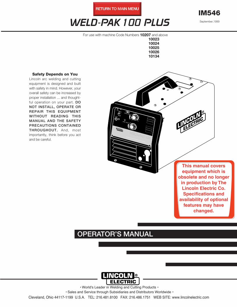
PROTECT YOURSELF AND OTHERS FROM POSSIBLE SERIOUS INJURY OR DEATH. KEEP CHILDREN
AWAY. PACEMAKER WEARERS SHOULD CONSULT WITH THEIR DOCTOR BEFORE OPERATING.
Read and understand the following safety highlights. For additional safety information, it is strongly recommended that you pur-chase a copy of “Safety in Welding & Cutting - ANSI Standard Z49.1” from the American Welding Society, P.O. Box 351040,Miami, Florida 33135 or CSA Standard W117.2-1974. A Free copy of “Arc Welding Safety” booklet E205 is available from theLincoln Electric Company, 22801 St. Clair Avenue, Cleveland, Ohio 44117-1199.
BE SURE THAT ALL INSTALLATION, OPERATION, MAINTENANCE AND REPAIR PROCEDURES ARE PER-
FORMED ONLY BY QUALIFIED INDIVIDUALS.
ARC RAYS can burn.2.a. Use a shield with the proper filter and cover
plates to protect your eyes from sparks andthe rays of the arc when welding or observingopen arc welding. Headshield and filter lensshould conform to ANSI Z87. I standards.
2.b. Use suitable clothing made from durable flame-resistantmaterial to protect your skin and that of your helpers fromthe arc rays.
2.c. Protect other nearby personnel with suitable, non-flammablescreening and/or warn them not to watch the arc nor exposethemselves to the arc rays or to hot spatter or metal.
ELECTRIC SHOCK can
kill.1.a. The electrode and work (or ground) circuits
are electrically “hot” when the welder is on.Do not touch these “hot” parts with your bareskin or wet clothing. Wear dry, hole-freegloves to insulate hands.
1.b. Insulate yourself from work and ground using dry insulation.Make certain the insulation is large enough to cover your fullarea of physical contact with work and ground.
In addition to the normal safety precautions, if welding
must be performed under electrically hazardous
conditions (in damp locations or while wearing wet
clothing; on metal structures such as floors, gratings or
scaffolds; when in cramped positions such as sitting,
kneeling or Iying, if there is a high risk of unavoidable or
accidental contact with the workpiece or ground) use
the following equipment:
• Semiautomatic DC Constant Voltage (Wire) Welder.
• DC Manual (Stick) Welder.
• AC Welder with Reduced Voltage Control.
1.c. In semiautomatic or automatic wire welding, the electrode,electrode reel, welding head, nozzle or semiautomaticwelding gun are also electrically “hot”.
1.d. Always be sure the work cable makes a good electricalconnection with the metal being welded. The connectionshould be as close as possible to the area being welded.
1.e. Ground the work or metal to be welded to a good electrical(earth) ground.
1.f. Maintain the electrode holder, work clamp, welding cable andwelding machine in good, safe operating condition. Replacedamaged insulation.
1.g. Never dip the electrode in water for cooling.
1.h. Never simultaneously touch electrically “hot” parts ofelectrode holders connected to two welders because voltagebetween the two can be the total of the open circuit voltageof both welders.
1.i. When working above floor level, use a safety belt to protectyourself from a fall should you get a shock.
1.j. Also see Items 4.c. and 6.
WARNING ARC WELDING can be hazardous.
FUMES AND GASES
can be dangerous.3.a. Welding may produce fumes and gases
hazardous to health. Avoid breathing thesefumes and gases.When welding, keepyour head out of the fume. Use enoughventilation and/or exhaust at the arc to keep
fumes and gases away from the breathing zone. When
welding with electrodes which require special
ventilation such as stainless or hard facing (see
instructions on container or MSDS) or on lead or
cadmium plated steel and other metals or coatings
which produce highly toxic fumes, keep exposure as
low as possible and below Threshold Limit Values (TLV)
using local exhaust or mechanical ventilation. In
confined spaces or in some circumstances, outdoors, a
respirator may be required. Additional precautions are
also required when welding on galvanized steel.
3.b. Do not weld in locations near chlorinated hydrocarbon vaporscoming from degreasing, cleaning or spraying operations.The heat and rays of the arc can react with solvent vapors toform phosgene, a highly toxic gas, and other irritatingproducts.
3.c. Shielding gases used for arc welding can displace air andcause injury or death. Always use enough ventilation,especially in confined areas, to insure breathing air is safe.
3.d. Read and understand the manufacturerʼs instructions for thisequipment and the consumables to be used, including thematerial safety data sheet (MSDS) and follow youremployerʼs safety practices. MSDS forms are available fromyour welding distributor or from the manufacturer.
3.e. Also see item 7b.
Apr. ʻ93
ii
WELD-PAK 100
SAFETY
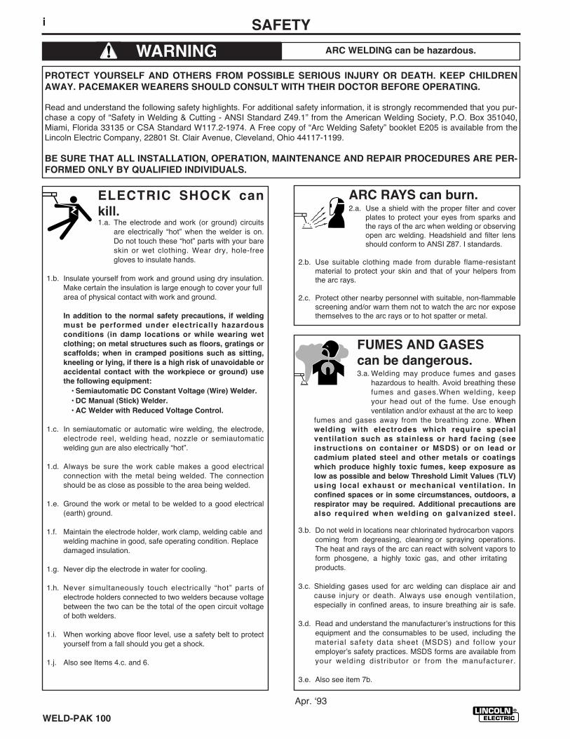
FOR ELECTRICALLYpowered equipment.
6.a. Turn off input power using the disconnectswitch at the fuse box before working onthe equipment.
6.b. Install equipment in accordance with the U.S. NationalElectrical Code, all local codes and the manufacturerʼsrecommendations.
6.c. Ground the equipment in accordance with the U.S. NationalElectrical Code and the manufacturerʼs recommendations.
CYLINDER may explode
if damaged.5.a. Use only compressed gas cylinders
containing the correct shielding gas for theprocess used and properly operatingregulators designed for the gas and
pressure used. All hoses, fittings, etc. should be suitable forthe application and maintained in good condition.
5.b. Always keep cylinders in an upright position securelychained to an undercarriage or fixed support.
5.c. Cylinders should be located:• Away from areas where they may be struck or subjected tophysical damage.
• A safe distance from arc welding or cutting operations andany other source of heat, sparks, or flame.
5.d. Never allow the electrode, electrode holder or any otherelectrically “hot” parts to touch a cylinder.
5.e. Keep your head and face away from the cylinder valve outletwhen opening the cylinder valve.
5.f. Valve protection caps should always be in place and handtight except when the cylinder is in use or connected foruse.
5.g. Read and follow the instructions on compressed gascylinders, associated equipment, and CGA publication P-l,“Precautions for Safe Handling of Compressed Gases inCylinders,” available from the Compressed Gas Association1235 Jefferson Davis Highway, Arlington, VA 22202.
Mar. ʻ93
WELDING SPARKS cancause fire or explosion.4.a. Remove fire hazards from the welding area.
If this is not possible, cover them to preventthe welding sparks from starting a fire.Remember that welding sparks and hot
materials from welding can easily go through small cracksand openings to adjacent areas. Avoid welding nearhydraulic lines. Have a fire extinguisher readily available.
4.b. Where compressed gases are to be used at the job site,special precautions should be used to prevent hazardoussituations. Refer to “Safety in Welding and Cutting” (ANSIStandard Z49.1) and the operating information for theequipment being used.
4.c. When not welding, make certain no part of the electrodecircuit is touching the work or ground. Accidental contactcan cause overheating and create a fire hazard.
4.d. Do not heat, cut or weld tanks, drums or containers until theproper steps have been taken to insure that such procedureswill not cause flammable or toxic vapors from substancesinside. They can cause an explosion even though they havebeen “cleaned”. For information, purchase “RecommendedSafe Practices for the Preparation for Welding and Cutting ofContainers and Piping That Have Held HazardousSubstances”, AWS F4.1 from the American Welding Society(see address above).
4.e. Vent hollow castings or containers before heating, cutting orwelding. They may explode.
4.f. Sparks and spatter are thrown from the welding arc. Wear oilfree protective garments such as leather gloves, heavy shirt,cuffless trousers, high shoes and a cap over your hair. Wearear plugs when welding out of position or in confined places.Always wear safety glasses with side shields when in awelding area.
4.g. Connect the work cable to the work as close to the weldingarea as practical. Work cables connected to the buildingframework or other locations away from the welding areaincrease the possibility of the welding current passingthrough lifting chains, crane cables or other alternate cir-cuits. This can create fire hazards or overheat lifting chainsor cables until they fail.
4.h. Also see item 7c.
iii SAFETY
WELD-PAK 100
Mar. ʻ93
ELECTRIC AND MAGNETIC
FIELDS
may be dangerous
8.a. Electric current flowing through any conductor causeslocalized Electric and Magnetic Fields (EMF). Weldingcurrent creates EMF fields around welding cables andwelding machines
8.b. EMF fields may interfere with some pacemakers, andwelders having a pacemaker should consult their physicianbefore welding.
8.c. Exposure to EMF fields in welding may have other healtheffects which are now not known.
8d. All welders should use the following procedures in order tominimize exposure to EMF fields from the welding circuit:
8.d.1. Route the electrode and work cables together - Securethem with tape when possible.
8.d.2. Never coil the electrode lead around your body.
8.d.3. Do not place your body between the electrode andwork cables. If the electrode cable is on your rightside, the work cable should also be on your right side.
8.d.4. Connect the work cable to the workpiece as close aspossible to the area being welded.
8.d.5. Do not work next to welding power source.
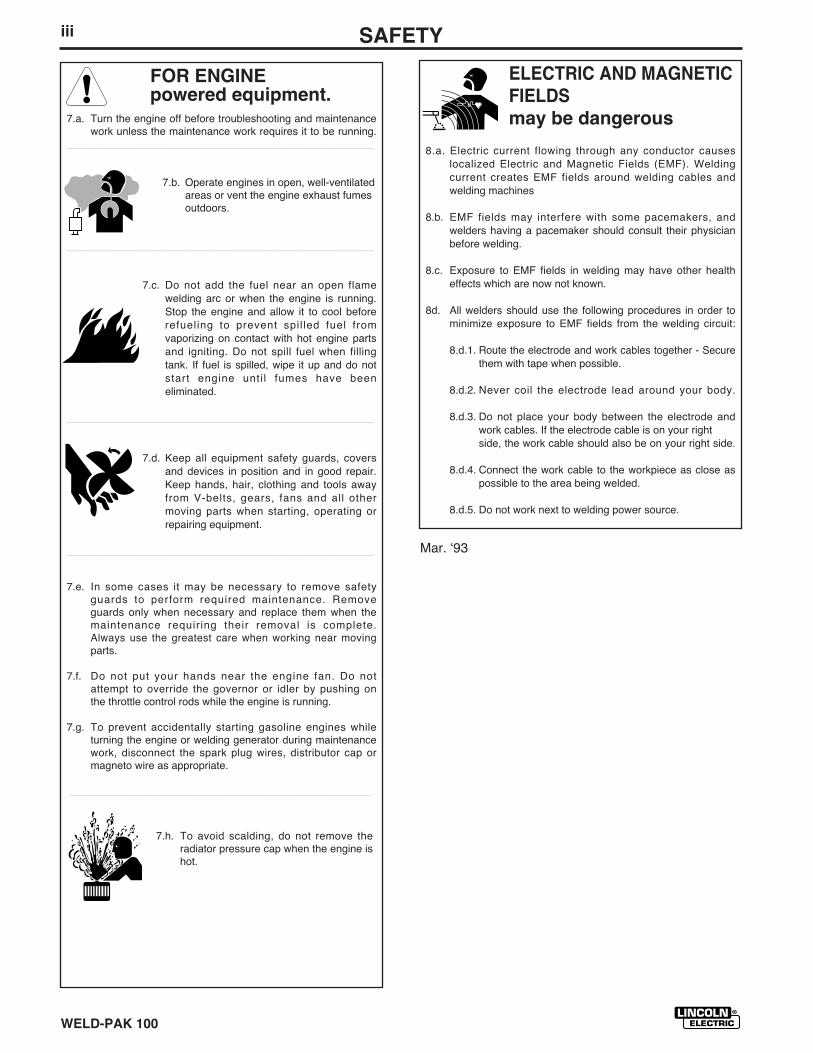
FOR ENGINEpowered equipment.
7.a. Turn the engine off before troubleshooting and maintenancework unless the maintenance work requires it to be running.
____________________________________________________
7.b. Operate engines in open, well-ventilatedareas or vent the engine exhaust fumesoutdoors.
____________________________________________________
7.c. Do not add the fuel near an open flamewelding arc or when the engine is running.Stop the engine and allow it to cool beforerefueling to prevent spil led fuel fromvaporizing on contact with hot engine partsand igniting. Do not spill fuel when fillingtank. If fuel is spilled, wipe it up and do notstart engine unti l fumes have beeneliminated.
____________________________________________________
7.d. Keep all equipment safety guards, coversand devices in position and in good repair.Keep hands, hair, clothing and tools awayfrom V-belts, gears, fans and all othermoving parts when starting, operating orrepairing equipment.
____________________________________________________
7.e. In some cases it may be necessary to remove safetyguards to perform required maintenance. Removeguards only when necessary and replace them when themaintenance requiring their removal is complete.Always use the greatest care when working near movingparts.
7.f. Do not put your hands near the engine fan. Do notattempt to override the governor or idler by pushing onthe throttle control rods while the engine is running.
7.g. To prevent accidentally starting gasoline engines whileturning the engine or welding generator during maintenancework, disconnect the spark plug wires, distributor cap ormagneto wire as appropriate.
___________________________________________________
7.h. To avoid scalding, do not remove theradiator pressure cap when the engine ishot.
ivSAFETY
WELD-PAK 100
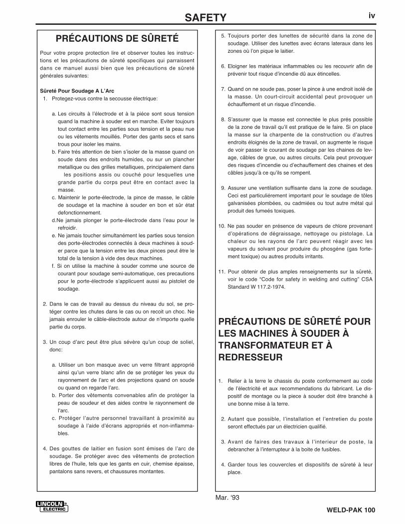
PRÉCAUTIONS DE SÛRETÉ
Pour votre propre protection lire et observer toutes les instruc-tions et les précautions de sûreté specifiques qui parraissentdans ce manuel aussi bien que les précautions de sûretégénérales suivantes:
Sûreté Pour Soudage A LʼArc
1. Protegez-vous contre la secousse électrique:
a. Les circuits à lʼélectrode et à la piéce sont sous tensionquand la machine à souder est en marche. Eviter toujourstout contact entre les parties sous tension et la peau nueou les vétements mouillés. Porter des gants secs et sanstrous pour isoler les mains.
b. Faire trés attention de bien sʼisoler de la masse quand onsoude dans des endroits humides, ou sur un planchermetallique ou des grilles metalliques, principalement dans
les positions assis ou couché pour lesquelles unegrande partie du corps peut être en contact avec lamasse.
c. Maintenir le porte-électrode, la pince de masse, le câblede soudage et la machine à souder en bon et sûr étatdefonctionnement.
d.Ne jamais plonger le porte-électrode dans lʼeau pour lerefroidir.
e. Ne jamais toucher simultanément les parties sous tensiondes porte-électrodes connectés à deux machines à soud-er parce que la tension entre les deux pinces peut être letotal de la tension à vide des deux machines.
f. Si on utilise la machine à souder comme une source decourant pour soudage semi-automatique, ces precautionspour le porte-électrode sʼapplicuent aussi au pistolet desoudage.
2. Dans le cas de travail au dessus du niveau du sol, se pro-téger contre les chutes dans le cas ou on recoit un choc. Nejamais enrouler le câble-électrode autour de nʼimporte quellepartie du corps.
3. Un coup dʼarc peut être plus sévère quʼun coup de soliel,donc:
a. Utiliser un bon masque avec un verre filtrant appropriéainsi quʼun verre blanc afin de se protéger les yeux durayonnement de lʼarc et des projections quand on soudeou quand on regarde lʼarc.
b. Porter des vêtements convenables afin de protéger lapeau de soudeur et des aides contre le rayonnement delʻarc.
c. Protéger lʼautre personnel travaillant à proximité ausoudage à lʼaide dʼécrans appropriés et non-inflamma-bles.
4. Des gouttes de laitier en fusion sont émises de lʼarc desoudage. Se protéger avec des vêtements de protectionlibres de lʼhuile, tels que les gants en cuir, chemise épaisse,pantalons sans revers, et chaussures montantes.
5. Toujours porter des lunettes de sécurité dans la zone desoudage. Utiliser des lunettes avec écrans lateraux dans leszones où lʼon pique le laitier.
6. Eloigner les matériaux inflammables ou les recouvrir afin deprévenir tout risque dʼincendie dû aux étincelles.
7. Quand on ne soude pas, poser la pince à une endroit isolé dela masse. Un court-circuit accidental peut provoquer unéchauffement et un risque dʼincendie.
8. Sʼassurer que la masse est connectée le plus prés possiblede la zone de travail quʼil est pratique de le faire. Si on placela masse sur la charpente de la construction ou dʼautresendroits éloignés de la zone de travail, on augmente le risquede voir passer le courant de soudage par les chaines de lev-age, câbles de grue, ou autres circuits. Cela peut provoquerdes risques dʼincendie ou dʼechauffement des chaines et descâbles jusquʼà ce quʼils se rompent.
9. Assurer une ventilation suffisante dans la zone de soudage.Ceci est particuliérement important pour le soudage de tôlesgalvanisées plombées, ou cadmiées ou tout autre métal quiproduit des fumeés toxiques.
10. Ne pas souder en présence de vapeurs de chlore provenantdʼopérations de dégraissage, nettoyage ou pistolage. Lachaleur ou les rayons de lʼarc peuvent réagir avec lesvapeurs du solvant pour produire du phosgéne (gas forte-ment toxique) ou autres produits irritants.
11. Pour obtenir de plus amples renseignements sur la sûreté,voir le code “Code for safety in welding and cutting” CSAStandard W 117.2-1974.
PRÉCAUTIONS DE SÛRETÉ POUR
LES MACHINES À SOUDER À
TRANSFORMATEUR ET À
REDRESSEUR
1. Relier à la terre le chassis du poste conformement au codede lʼélectricité et aux recommendations du fabricant. Le dis-positif de montage ou la piece à souder doit être branché àune bonne mise à la terre.
2. Autant que possible, Iʼinstallation et lʼentretien du posteseront effectués par un électricien qualifié.
3. Avant de faires des travaux à lʼinterieur de poste, ladebrancher à lʼinterrupteur à la boite de fusibles.
4. Garder tous les couvercles et dispositifs de sûreté à leurplace.
Mar. ʻ93
v
WELD-PAK 100
Thank Youfor selecting a QUALITY product by Lincoln Electric.We want you to take pride in operating this LincolnElectric Company product ••• as much pride as wehave in bringing this product to you!
Read this Operatorʼs Manual completely before attempting to use this equipment. Save this manual and keep ithandy for quick reference. Pay particular attention to the safety instructions we have provided for your protection.The level of seriousness to be applied to each is explained below:
WARNING
This statement appears where the information must be followed exactly to avoid serious personal injury orloss of life.
This statement appears where the information must be followed to avoid minor personal injury or damage to
this equipment.
CAUTION
Please Examine Carton and Equipment For Damage ImmediatelyWhen this equipment is shipped, title passes to the purchaser upon receipt by the carrier. Consequently, Claimsfor material damaged in shipment must be made by the purchaser against the transportation company at the timethe shipment is received.
Please record your equipment identification information below for future reference. This information can be foundon your machine nameplate.
Code Number _____________________________________
Serial Number _____________________________________
Model Name _____________________________________
Date of Purchase __________________________________
Whenever you request replacement parts for or information on this equipment always supply the information youhave recorded above.
vi
FEB 95 WELD-PAK 100
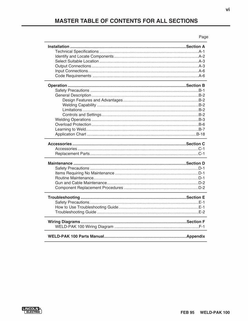
MASTER TABLE OF CONTENTS FOR ALL SECTIONS
Page
Installation .......................................................................................................Section A
Technical Specifications ........................................................................................A-1Identify and Locate Components ...........................................................................A-2Select Suitable Location ........................................................................................A-3Output Connections...............................................................................................A-3Input Connections..................................................................................................A-6Code Requirements ..............................................................................................A-6
Operation .........................................................................................................Section B
Safety Precautions ................................................................................................B-1General Description ...............................................................................................B-2
Design Features and Advantages...................................................................B-2Welding Capability ..........................................................................................B-2Limitations .......................................................................................................B-2Controls and Settings......................................................................................B-2
Welding Operations ...............................................................................................B-3Overload Protection...............................................................................................B-6Learning to Weld....................................................................................................B-7Application Chart .................................................................................................B-18
Accessories .....................................................................................................Section C
Accessories ...........................................................................................................C-1Replacement Parts ................................................................................................C-1
Maintenance ....................................................................................................Section D
Safety Precautions ................................................................................................D-1Items Requiring No Maintenance ..........................................................................D-1Routine Maintenance.............................................................................................D-1Gun and Cable Maintenance.................................................................................D-2Component Replacement Procedures ..................................................................D-2
Troubleshooting ..............................................................................................Section E
Safety Precautions.................................................................................................E-1How to Use Troubleshooting Guide.......................................................................E-1Troubleshooting Guide ..........................................................................................E-2
Wiring Diagrams ..............................................................................................Section F
WELD-PAK 100 Wiring Diagram ...........................................................................F-1
WELD-PAK 100 Parts Manual.........................................................................Appendix

WELD-PAK 100
vii
Fuse or
Output Mode Input Voltage Breaker Size Input Amps Power Cord Extension Cord
RATED 115V/60Hz 20 Amp 20 15 Amp, 125V, Three Conductor
Three Prong Plug #14 AWG
(NEMA Type 5-15P) (2.1 mm2) or LargerUp to 25 Ft. (7.6 mm)
CSA 115V/60Hz 15 Amp 12 15 Amp, 125V, Three ConductorThree Prong Plug #12 AWG
(NEMA Type 5-15P) (3.3 mm2) or LargerUp to 50 Ft. (15.2 mm)
A-1INSTALLATION
WELD-PAK 100
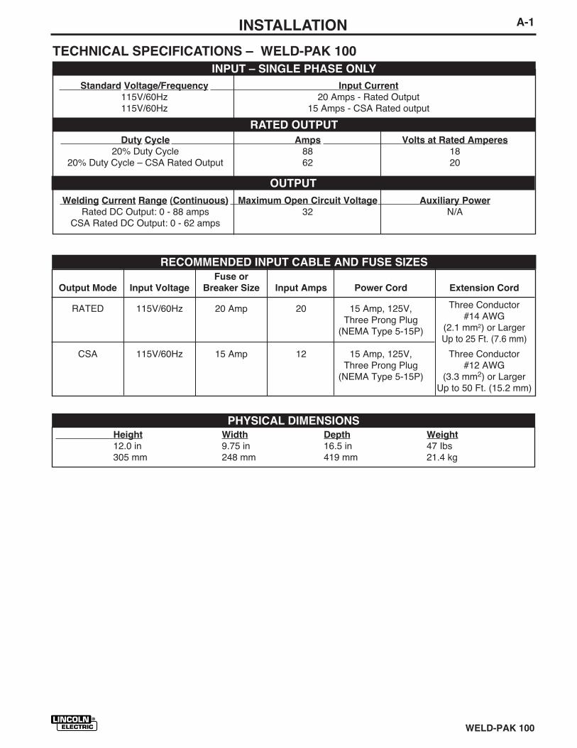
TECHNICAL SPECIFICATIONS – WELD-PAK 100
INPUT – SINGLE PHASE ONLY
RATED OUTPUT
OUTPUT
RECOMMENDED INPUT CABLE AND FUSE SIZES
Height Width Depth Weight
12.0 in 9.75 in 16.5 in 47 Ibs305 mm 248 mm 419 mm 21.4 kg
PHYSICAL DIMENSIONS
Standard Voltage/Frequency Input Current
115V/60Hz 20 Amps - Rated Output115V/60Hz 15 Amps - CSA Rated output
Duty Cycle Amps Volts at Rated Amperes
20% Duty Cycle 88 1820% Duty Cycle – CSA Rated Output 62 20
Welding Current Range (Continuous) Maximum Open Circuit Voltage Auxiliary Power
Rated DC Output: 0 - 88 amps 32 N/ACSA Rated DC Output: 0 - 62 amps
A-2 INSTALLATION
WELD-PAK 100 JAN96
Read entire installation section before starting
installation.
SAFETY PRECAUTIONS
IDENTIFY AND LOCATECOMPONENTS
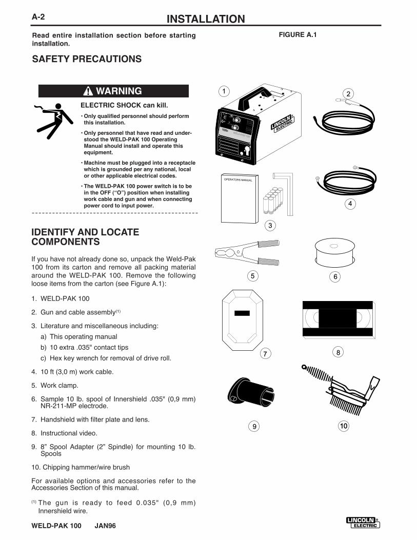
If you have not already done so, unpack the Weld-Pak100 from its carton and remove all packing materialaround the WELD-PAK 100. Remove the followingloose items from the carton (see Figure A.1):
1. WELD-PAK 100
2. Gun and cable assembly(1)
3. Literature and miscellaneous including:
a) This operating manual
b) 10 extra .035" contact tips
c) Hex key wrench for removal of drive roll.
4. 10 ft (3,0 m) work cable.
5. Work clamp.
6. Sample 10 lb. spool of Innershield .035" (0,9 mm)NR-211-MP electrode.
7. Handshield with filter plate and lens.
8. Instructional video.
9. 8” Spool Adapter (2” Spindle) for mounting 10 lb.Spools
10. Chipping hammer/wire brush
For available options and accessories refer to theAccessories Section of this manual.
(1) The gun is ready to feed 0.035" (0,9 mm)Innershield wire.
ELECTRIC SHOCK can kill.
• Only qualified personnel should perform
this installation.
• Only personnel that have read and under-
stood the WELD-PAK 100 Operating
Manual should install and operate this
equipment.
• Machine must be plugged into a receptacle
which is grounded per any national, local
or other applicable electrical codes.
• The WELD-PAK 100 power switch is to be
in the OFF (“O”) position when installing
work cable and gun and when connecting
power cord to input power.
WARNING
FIGURE A.1
WELD-PAK 100
WELD-PAK 100
1 2
3
4
5 6
7 8
10109
A-3INSTALLATION
WELD-PAK 100
SELECT SUITABLE LOCATION
Locate the welder in a dry location where there is freecirculation of clean air into the louvers in the back andout the front of the unit. A location that minimizes theamount of smoke and dirt drawn into the rear louversreduces the chance of dirt accumulation that can blockair passages and cause overheating.
STACKING
WELD-PAK 100ʼs cannot be stacked.
TILTING
Each machine must be placed on a secure, level sur-face, either directly or on a recommended undercar-riage. The machine may topple over if this procedureis not followed.
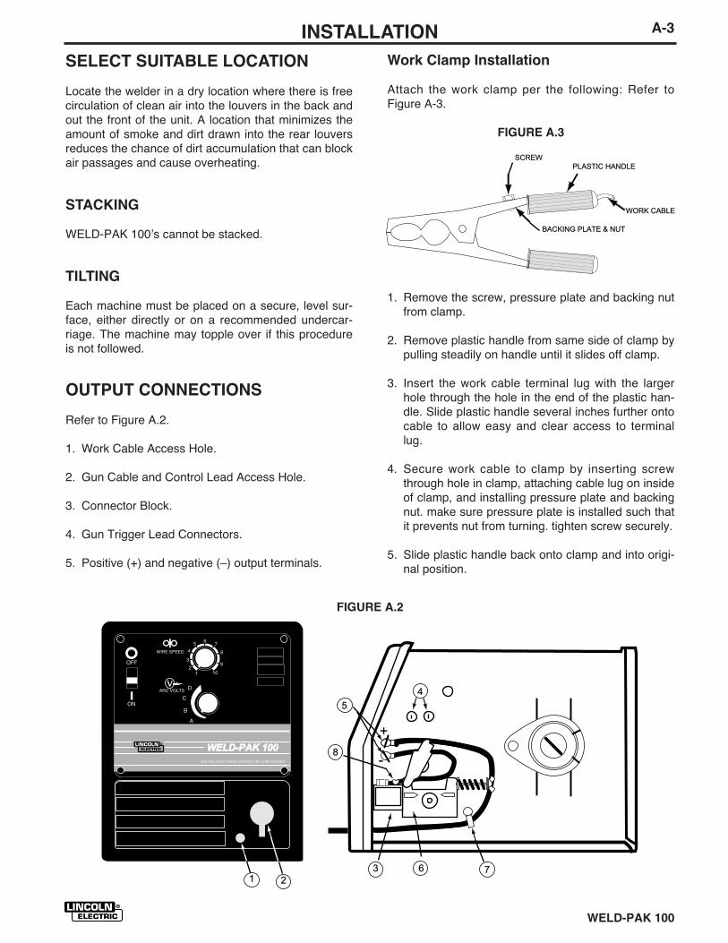
OUTPUT CONNECTIONS
Refer to Figure A.2.
1. Work Cable Access Hole.
2. Gun Cable and Control Lead Access Hole.
3. Connector Block.
4. Gun Trigger Lead Connectors.
5. Positive (+) and negative (–) output terminals.
Work Clamp Installation
Attach the work clamp per the following: Refer toFigure A-3.
FIGURE A.3
WELD-PAK 100WELD-PAK 100
45
8
3 6 71 2
+
-
1. Remove the screw, pressure plate and backing nutfrom clamp.
2. Remove plastic handle from same side of clamp bypulling steadily on handle until it slides off clamp.
3. Insert the work cable terminal lug with the largerhole through the hole in the end of the plastic han-dle. Slide plastic handle several inches further ontocable to allow easy and clear access to terminallug.
4. Secure work cable to clamp by inserting screwthrough hole in clamp, attaching cable lug on insideof clamp, and installing pressure plate and backingnut. make sure pressure plate is installed such thatit prevents nut from turning. tighten screw securely.
5. Slide plastic handle back onto clamp and into origi-nal position.
FIGURE A.2
SCREWSCREWPLASTIC HANDLEPLASTIC HANDLE
WORK CABLEWORK CABLE
BACKING PLATE & NUTBACKING PLATE & NUT
1
2
4
3
A-4 INSTALLATION
WELD-PAK 100
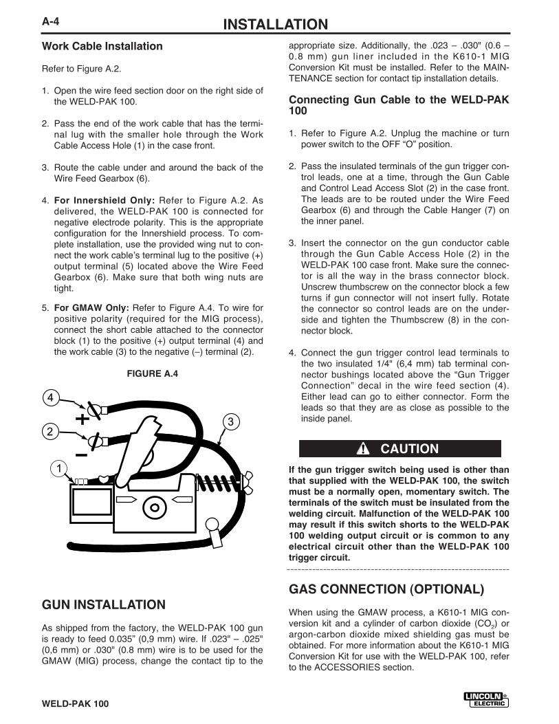
Work Cable Installation
Refer to Figure A.2.
1. Open the wire feed section door on the right side ofthe WELD-PAK 100.
2. Pass the end of the work cable that has the termi-nal lug with the smaller hole through the WorkCable Access Hole (1) in the case front.
3. Route the cable under and around the back of theWire Feed Gearbox (6).
4. For Innershield Only: Refer to Figure A.2. Asdelivered, the WELD-PAK 100 is connected fornegative electrode polarity. This is the appropriateconfiguration for the Innershield process. To com-plete installation, use the provided wing nut to con-nect the work cableʼs terminal lug to the positive (+)output terminal (5) located above the Wire FeedGearbox (6). Make sure that both wing nuts aretight.
5. For GMAW Only: Refer to Figure A.4. To wire forpositive polarity (required for the MIG process),connect the short cable attached to the connectorblock (1) to the positive (+) output terminal (4) andthe work cable (3) to the negative (–) terminal (2).
FIGURE A.4
appropriate size. Additionally, the .023 – .030" (0.6 –0.8 mm) gun liner included in the K610-1 MIGConversion Kit must be installed. Refer to the MAIN-TENANCE section for contact tip installation details.
Connecting Gun Cable to the WELD-PAK100
1. Refer to Figure A.2. Unplug the machine or turnpower switch to the OFF “O” position.
2. Pass the insulated terminals of the gun trigger con-trol leads, one at a time, through the Gun Cableand Control Lead Access Slot (2) in the case front.The leads are to be routed under the Wire FeedGearbox (6) and through the Cable Hanger (7) onthe inner panel.
3. Insert the connector on the gun conductor cablethrough the Gun Cable Access Hole (2) in theWELD-PAK 100 case front. Make sure the connec-tor is all the way in the brass connector block.Unscrew thumbscrew on the connector block a fewturns if gun connector will not insert fully. Rotatethe connector so control leads are on the under-side and tighten the Thumbscrew (8) in the con-nector block.
4. Connect the gun trigger control lead terminals tothe two insulated 1/4" (6,4 mm) tab terminal con-nector bushings located above the “Gun TriggerConnection” decal in the wire feed section (4).Either lead can go to either connector. Form theleads so that they are as close as possible to theinside panel.
If the gun trigger switch being used is other than
that supplied with the WELD-PAK 100, the switch
must be a normally open, momentary switch. The
terminals of the switch must be insulated from the
welding circuit. Malfunction of the WELD-PAK 100
may result if this switch shorts to the WELD-PAK
100 welding output circuit or is common to any
electrical circuit other than the WELD-PAK 100
trigger circuit.
GAS CONNECTION (OPTIONAL)
When using the GMAW process, a K610-1 MIG con-version kit and a cylinder of carbon dioxide (CO2) orargon-carbon dioxide mixed shielding gas must beobtained. For more information about the K610-1 MIGConversion Kit for use with the WELD-PAK 100, referto the ACCESSORIES section.
CAUTION
GUN INSTALLATION
As shipped from the factory, the WELD-PAK 100 gunis ready to feed 0.035” (0,9 mm) wire. If .023" – .025"(0,6 mm) or .030" (0.8 mm) wire is to be used for theGMAW (MIG) process, change the contact tip to the
A-5INSTALLATION
WELD-PAK 100
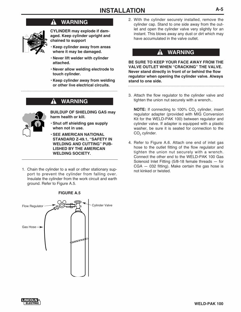
2. With the cylinder securely installed, remove thecylinder cap. Stand to one side away from the out-let and open the cylinder valve very slightly for aninstant. This blows away any dust or dirt which mayhave accumulated in the valve outlet.
BE SURE TO KEEP YOUR FACE AWAY FROM THE
VALVE OUTLET WHEN “CRACKING” THE VALVE.
Never stand directly in front of or behind the flow
regulator when opening the cylinder valve. Always
stand to one side.
3. Attach the flow regulator to the cylinder valve andtighten the union nut securely with a wrench..
NOTE: If connecting to 100% CO2 cylinder, insertregulator adapter (provided with MIG ConversionKit for the WELD-PAK 100) between regulator andcylinder valve. If adapter is equipped with a plasticwasher, be sure it is seated for connection to theCO2 cylinder.
4. Refer to Figure A.6. Attach one end of inlet gashose to the outlet fitting of the flow regulator andtighten the union nut securely with a wrench.Connect the other end to the WELD-PAK 100 GasSolenoid Inlet Fitting (5/8-18 female threads — forCGA — 032 fitting). Make certain the gas hose isnot kinked or twisted.
CYLINDER may explode if dam-
aged. Keep cylinder upright and
chained to support
• Keep cylinder away from areas
where it may be damaged.
• Never lift welder with cylinder
attached.
• Never allow welding electrode to
touch cylinder.
• Keep cylinder away from welding
or other live electrical circuits.
BUILDUP OF SHIELDING GAS may
harm health or kill.
• Shut off shielding gas supply
when not in use.
• SEE AMERICAN NATIONAL
STANDARD Z-49.1, “SAFETY IN
WELDING AND CUTTING” PUB-
LISHED BY THE AMERICAN
WELDING SOCIETY.
1. Chain the cylinder to a wall or other stationary sup-port to prevent the cylinder from falling over.Insulate the cylinder from the work circuit and earthground. Refer to Figure A.5.
FIGURE A.5
WARNING
WARNING
Cylinder Valve
Gas Hose
Flow Regulator
WARNING
A-6 INSTALLATION
WELD-PAK 100
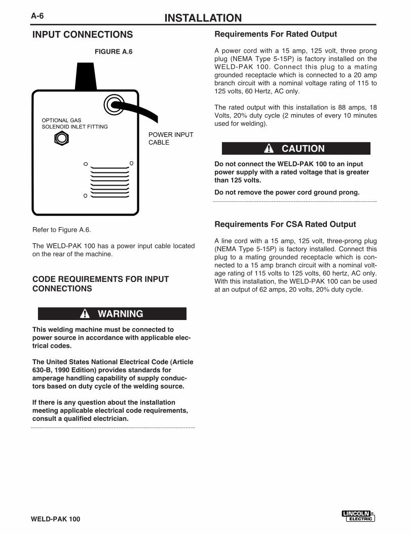
INPUT CONNECTIONS
FIGURE A.6
Refer to Figure A.6.
The WELD-PAK 100 has a power input cable locatedon the rear of the machine.
CODE REQUIREMENTS FOR INPUTCONNECTIONS
This welding machine must be connected to
power source in accordance with applicable elec-
trical codes.
The United States National Electrical Code (Article
630-B, 1990 Edition) provides standards for
amperage handling capability of supply conduc-
tors based on duty cycle of the welding source.
If there is any question about the installation
meeting applicable electrical code requirements,
consult a qualified electrician.
Requirements For Rated Output
A power cord with a 15 amp, 125 volt, three prongplug (NEMA Type 5-15P) is factory installed on theWELD-PAK 100. Connect this plug to a matinggrounded receptacle which is connected to a 20 ampbranch circuit with a nominal voltage rating of 115 to125 volts, 60 Hertz, AC only.
The rated output with this installation is 88 amps, 18Volts, 20% duty cycle (2 minutes of every 10 minutesused for welding).
Do not connect the WELD-PAK 100 to an input
power supply with a rated voltage that is greater
than 125 volts.
Do not remove the power cord ground prong.
Requirements For CSA Rated Output
A line cord with a 15 amp, 125 volt, three-prong plug(NEMA Type 5-15P) is factory installed. Connect thisplug to a mating grounded receptacle which is con-nected to a 15 amp branch circuit with a nominal volt-age rating of 115 volts to 125 volts, 60 hertz, AC only.With this installation, the WELD-PAK 100 can be usedat an output of 62 amps, 20 volts, 20% duty cycle.
WARNING
CAUTION
POWER INPUT CABLE
OPTIONAL GAS SOLENOID INLET FITTING
WELD-PAK 100
B-1OPERATION
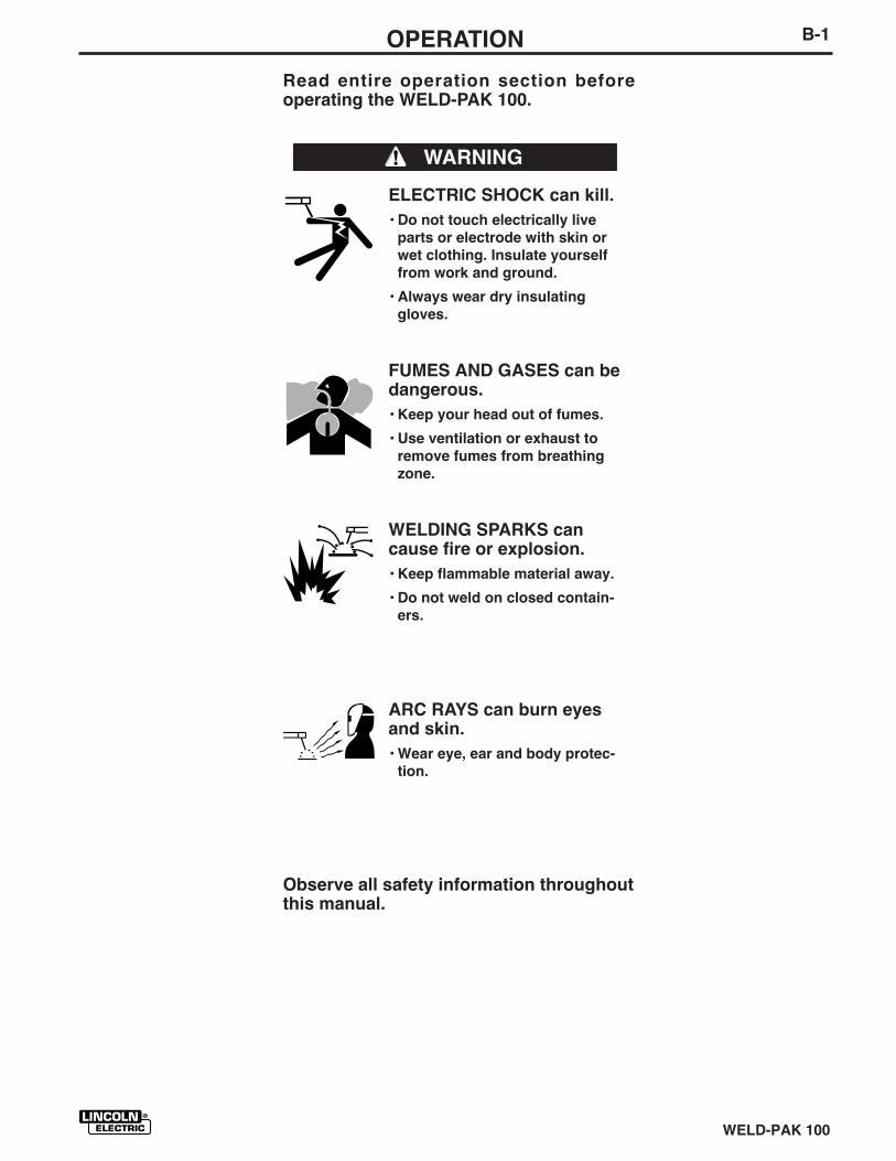
Read entire operation section beforeoperating the WELD-PAK 100.
ELECTRIC SHOCK can kill.
• Do not touch electrically live
parts or electrode with skin or
wet clothing. Insulate yourself
from work and ground.
• Always wear dry insulating
gloves.
FUMES AND GASES can bedangerous.
• Keep your head out of fumes.
• Use ventilation or exhaust to
remove fumes from breathing
zone.
WELDING SPARKS cancause fire or explosion.
• Keep flammable material away.
• Do not weld on closed contain-
ers.
ARC RAYS can burn eyesand skin.
• Wear eye, ear and body protec-
tion.
Observe all safety information throughoutthis manual.
WARNING
WELD-PAK 100 JAN96
B-2 OPERATION
GENERAL DESCRIPTION
The WELD-PAK 100 is a compact lightweight DC wirefeeder/power source. It has been designed for work-shop, hobby, and light maintenance. It is capable ofgeneral purpose welding with self-shielded flux-cored(Innershield®) wire. When combined with the optionalK610-1 MIG Conversion Kit, the WELD-PAK 100 issuitable for GMAW (MIG) welding applications.
The WELD-PAK 100 is ideally suited for individualshaving access to 115 volt AC input power, and wanti-ng the ease of use, quality and dependability of bothgas metal arc welding or GMAW (also known as MIGwelding) and the Innershield electrode process (selfshielded flux cored or FCAW). The WELD-PAK 100 isa rugged and reliable machine that has beendesigned for dependable service and long life.
RECOMMENDED PROCESSES
The WELD-PAK 100 can be used for welding mildsteel using the self shielded, Innershield electrodeprocess (FCAW) or it can be used for the GMAW, sin-gle pass, process which requires a supply of shieldinggas and the K610-1 MIG Conversion Kit. The WELD-PAK 100 is configured for use with the FCAW processas delivered from the factory.
OPERATIONAL FEATURES ANDCONTROLS
The WELD-PAK 100 has the following controls asstandard: Power ON/OFF Switch, Voltage Control,Wire Speed Control, Trigger Switch, and a CircuitBreaker.
DESIGN FEATURES ANDADVANTAGES
● Operates on 115 volt input — no special wiringrequired.
● “Cold electrode” until gun trigger is pressed for anadded measure of safety.
● Overload protection — incorporates both a thermo-stat and a circuit breaker.
● Quality wire drive with electronic overload protec-tion.
● “Quick Release” idle roll pressure arm is easilyadjusted.
● Reversible, dual groove drive roll. Drive roll willfeed .023 – .025” (0.6 mm) and .030" and .035"(0.8 mm and 0.9 mm) diameter wire.
● No external shielding gas is required when usedwith Lincoln Innershield .035” (0,9 mm) NR®-211-MP electrode.
● Accommodates 4” (100 mm) diameter spool ofwire. Will accommodate 8” (200 mm) diameter withoptional spindle.
WELDING CAPABILITY
The WELD-PAK 100 is rated at 88 amps, 18 volts, at20% duty cycle on a ten minute basis. CSA rated out-put at 62 amps at 20 volts at 20% duty cycle. It iscapable of higher output currents at lower duty cycles.
LIMITATIONS
Arc Gouging cannot be performed with the WELD-PAK 100. The WELD-PAK 100 is not recommendedfor pipe thawing or TIG welding.
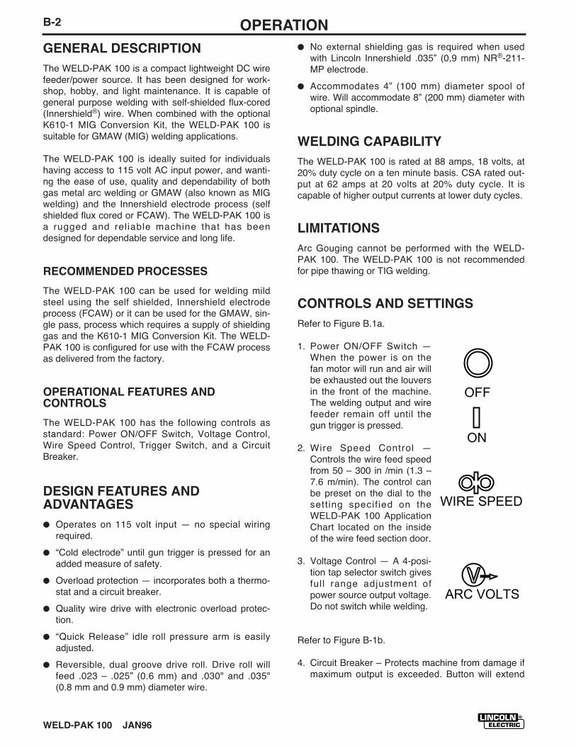
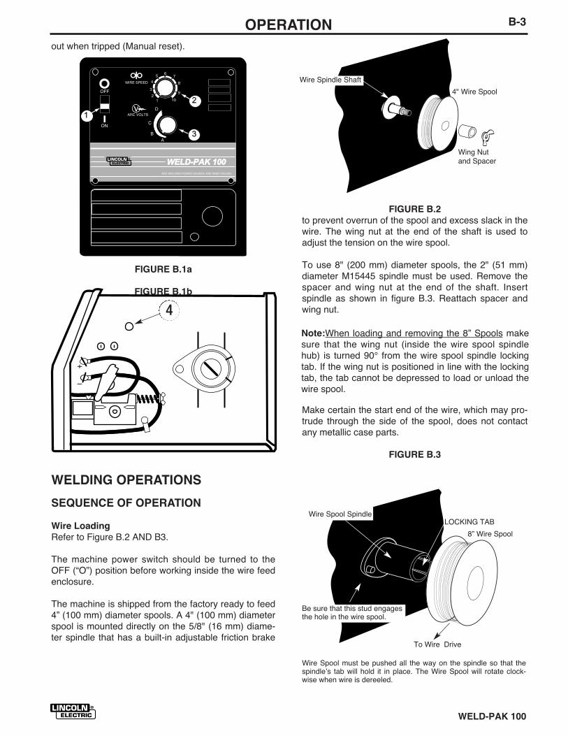
CONTROLS AND SETTINGS
Refer to Figure B.1a.
1. Power ON/OFF Switch —When the power is on thefan motor will run and air willbe exhausted out the louversin the front of the machine.The welding output and wirefeeder remain off until thegun trigger is pressed.
2. Wire Speed Control —Controls the wire feed speedfrom 50 – 300 in /min (1.3 –7.6 m/min). The control canbe preset on the dial to thesetting specif ied on theWELD-PAK 100 ApplicationChart located on the insideof the wire feed section door.
3. Voltage Control — A 4-posi-tion tap selector switch givesfull range adjustment ofpower source output voltage.Do not switch while welding.
Refer to Figure B-1b.
4. Circuit Breaker – Protects machine from damage ifmaximum output is exceeded. Button will extend
OFF
ON
ARC VOLTS
WIRE SPEED
WELD-PAK 100
B-3OPERATION
out when tripped (Manual reset).
FIGURE B.1a
FIGURE B.1b
WELDING OPERATIONS
SEQUENCE OF OPERATION
Wire Loading
Refer to Figure B.2 AND B3.
The machine power switch should be turned to theOFF (“O”) position before working inside the wire feedenclosure.
The machine is shipped from the factory ready to feed4” (100 mm) diameter spools. A 4" (100 mm) diameterspool is mounted directly on the 5/8" (16 mm) diame-ter spindle that has a built-in adjustable friction brake
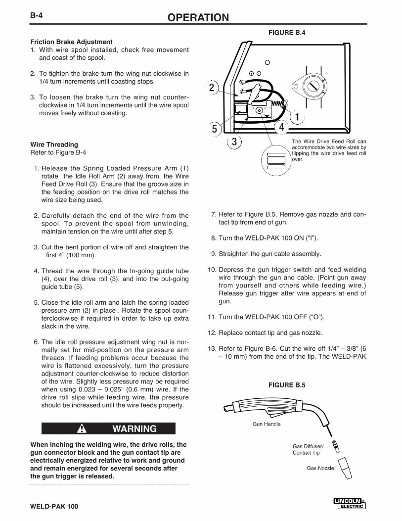
FIGURE B.2
to prevent overrun of the spool and excess slack in thewire. The wing nut at the end of the shaft is used toadjust the tension on the wire spool.
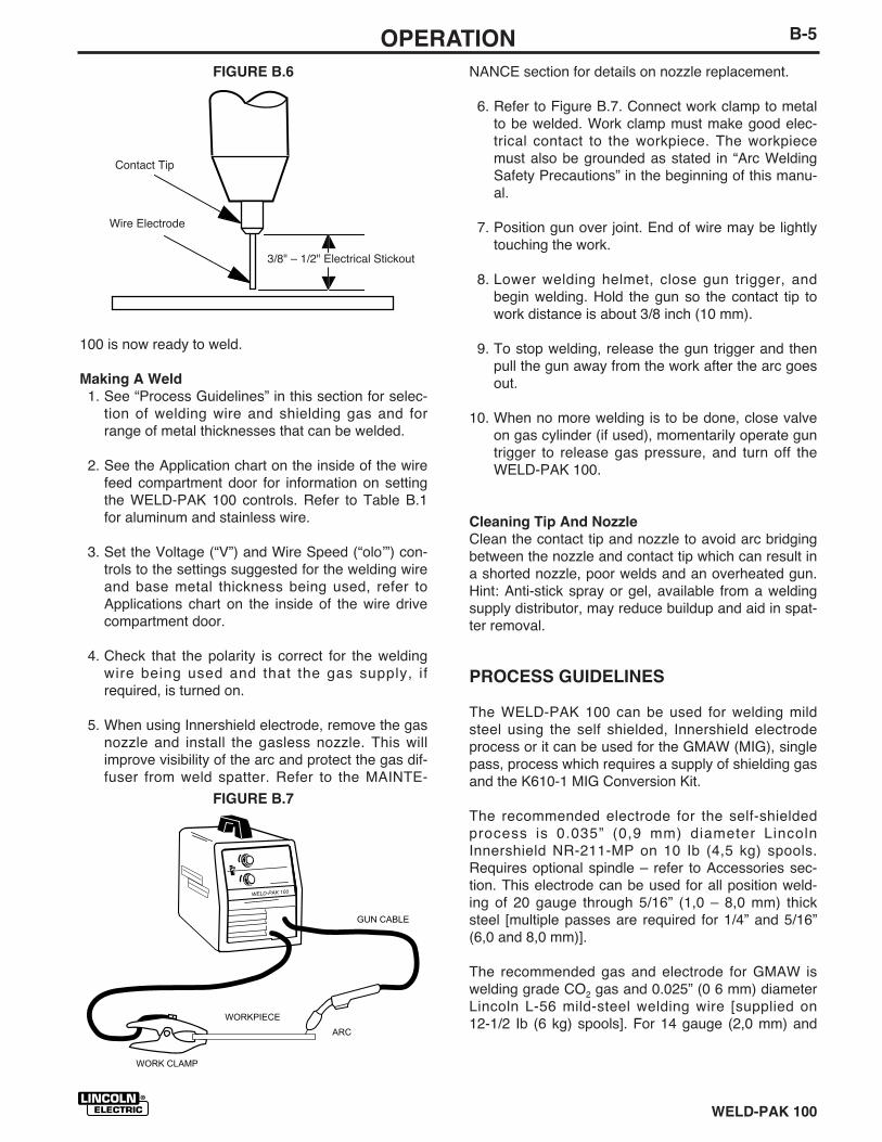
To use 8" (200 mm) diameter spools, the 2" (51 mm)diameter M15445 spindle must be used. Remove thespacer and wing nut at the end of the shaft. Insertspindle as shown in figure B.3. Reattach spacer andwing nut.
Make certain the start end of the wire, which may pro-trude through the side of the spool, does not contactany metallic case parts.
FIGURE B.3
WELD-PAK 100WELD-PAK 100
3
2
1
4
Wire Spool must be pushed all the way on the spindle so that thespindleʼs tab will hold it in place. The Wire Spool will rotate clock-wise when wire is dereeled.
8” Wire Spool
Wire Spool Spindle
Be sure that this stud engagesthe hole in the wire spool.
To Wire Drive
Note:When loading and removing the 8” Spools makesure that the wing nut (inside the wire spool spindlehub) is turned 90° from the wire spool spindle lockingtab. If the wing nut is positioned in line with the lockingtab, the tab cannot be depressed to load or unload thewire spool.
LOCKING TAB
Wire Spindle Shaft
4" Wire Spool
Wing Nutand Spacer
WELD-PAK 100
B-4 OPERATION
Friction Brake Adjustment
1. With wire spool installed, check free movementand coast of the spool.
2. To tighten the brake turn the wing nut clockwise in1/4 turn increments until coasting stops.
3. To loosen the brake turn the wing nut counter-clockwise in 1/4 turn increments until the wire spoolmoves freely without coasting.
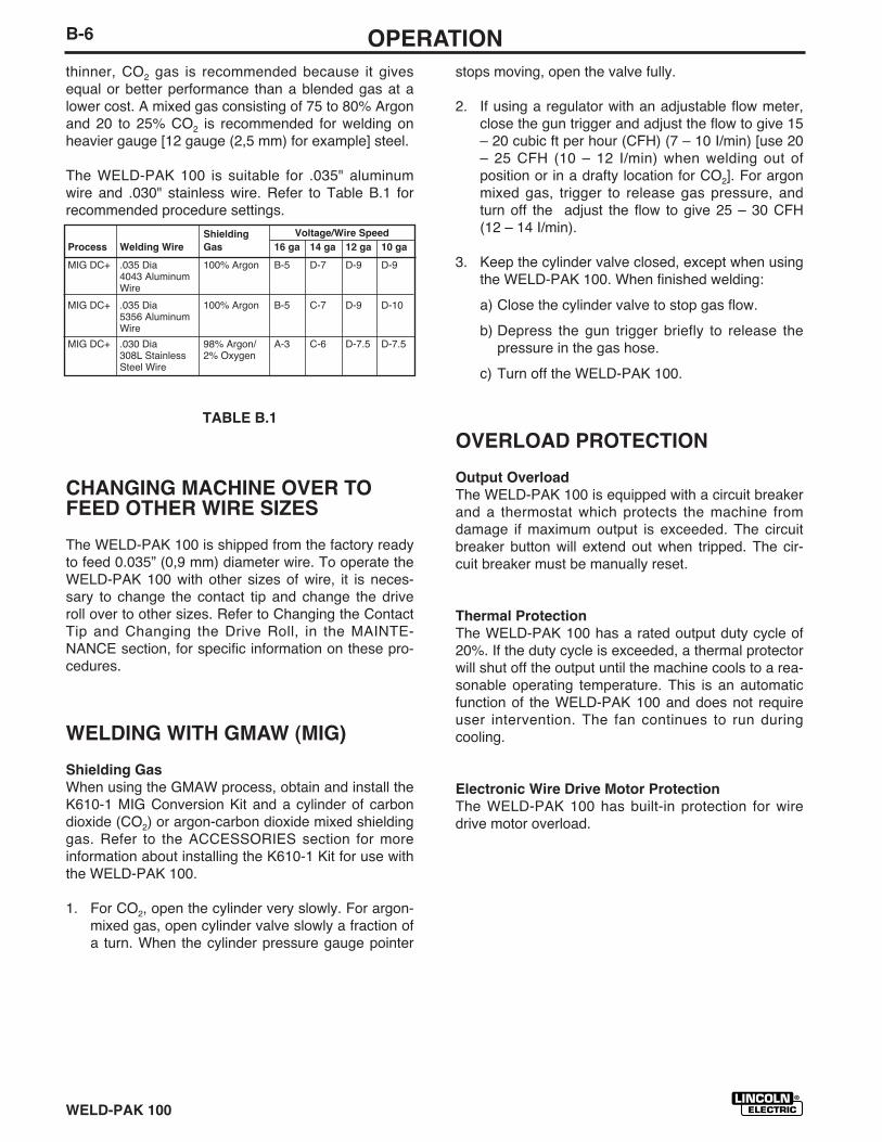
Wire Threading
Refer to Figure B-4
1. Release the Spring Loaded Pressure Arm (1)rotate the Idle Roll Arm (2) away from. the WireFeed Drive Roll (3). Ensure that the groove size inthe feeding position on the drive roll matches thewire size being used.
2. Carefully detach the end of the wire from thespool. To prevent the spool from unwinding,maintain tension on the wire until after step 5.
3. Cut the bent portion of wire off and straighten thefirst 4” (100 mm).
4. Thread the wire through the In-going guide tube(4), over the drive roll (3), and into the out-goingguide tube (5).
5. Close the idle roll arm and latch the spring loadedpressure arm (2) in place . Rotate the spool coun-terclockwise if required in order to take up extraslack in the wire.
6. The idle roll pressure adjustment wing nut is nor-mally set for mid-position on the pressure armthreads. If feeding problems occur because thewire is flattened excessively, turn the pressureadjustment counter-clockwise to reduce distortionof the wire. Slightly less pressure may be requiredwhen using 0.023 – 0.025” (0,6 mm) wire. If thedrive roll slips while feeding wire, the pressureshould be increased until the wire feeds properly.
When inching the welding wire, the drive rolls, the
gun connector block and the gun contact tip are
electrically energized relative to work and ground
and remain energized for several seconds after
the gun trigger is released.
7. Refer to Figure B.5. Remove gas nozzle and con-tact tip from end of gun.
8. Turn the WELD-PAK 100 ON (“I”).
9. Straighten the gun cable assembly.
10. Depress the gun trigger switch and feed weldingwire through the gun and cable. (Point gun awayfrom yourself and others while feeding wire.)Release gun trigger after wire appears at end ofgun.
11. Turn the WELD-PAK 100 OFF (“O”).
12. Replace contact tip and gas nozzle.
13. Refer to Figure B-6. Cut the wire off 1/4” – 3/8” (6– 10 mm) from the end of the tip. The WELD-PAK
WARNING
FIGURE B.4
The Wire Drive Feed Roll canaccommodate two wire sizes byflipping the wire drive feed rollover.
FIGURE B.5
Gun Handle
Gas Diffuser/Contact Tip
Gas Nozzle
1
2
345
WELD-PAK 100
B-5OPERATION
100 is now ready to weld.
Making A Weld
1. See “Process Guidelines” in this section for selec-tion of welding wire and shielding gas and forrange of metal thicknesses that can be welded.
2. See the Application chart on the inside of the wirefeed compartment door for information on settingthe WELD-PAK 100 controls. Refer to Table B.1for aluminum and stainless wire.
3. Set the Voltage (“V”) and Wire Speed (“oloʼ”) con-trols to the settings suggested for the welding wireand base metal thickness being used, refer toApplications chart on the inside of the wire drivecompartment door.
4. Check that the polarity is correct for the weldingwire being used and that the gas supply, ifrequired, is turned on.
5. When using Innershield electrode, remove the gasnozzle and install the gasless nozzle. This willimprove visibility of the arc and protect the gas dif-fuser from weld spatter. Refer to the MAINTE-
FIGURE B.6 NANCE section for details on nozzle replacement.
6. Refer to Figure B.7. Connect work clamp to metalto be welded. Work clamp must make good elec-trical contact to the workpiece. The workpiecemust also be grounded as stated in “Arc WeldingSafety Precautions” in the beginning of this manu-al.
7. Position gun over joint. End of wire may be lightlytouching the work.
8. Lower welding helmet, close gun trigger, andbegin welding. Hold the gun so the contact tip towork distance is about 3/8 inch (10 mm).
9. To stop welding, release the gun trigger and thenpull the gun away from the work after the arc goesout.
10. When no more welding is to be done, close valveon gas cylinder (if used), momentarily operate guntrigger to release gas pressure, and turn off theWELD-PAK 100.
Cleaning Tip And Nozzle
Clean the contact tip and nozzle to avoid arc bridgingbetween the nozzle and contact tip which can result ina shorted nozzle, poor welds and an overheated gun.Hint: Anti-stick spray or gel, available from a weldingsupply distributor, may reduce buildup and aid in spat-ter removal.
PROCESS GUIDELINES
The WELD-PAK 100 can be used for welding mildsteel using the self shielded, Innershield electrodeprocess or it can be used for the GMAW (MIG), singlepass, process which requires a supply of shielding gasand the K610-1 MIG Conversion Kit.
The recommended electrode for the self-shieldedprocess is 0.035” (0,9 mm) diameter LincolnInnershield NR-211-MP on 10 Ib (4,5 kg) spools.Requires optional spindle – refer to Accessories sec-tion. This electrode can be used for all position weld-ing of 20 gauge through 5/16” (1,0 – 8,0 mm) thicksteel [multiple passes are required for 1/4” and 5/16”(6,0 and 8,0 mm)].
The recommended gas and electrode for GMAW iswelding grade CO2 gas and 0.025” (0 6 mm) diameterLincoln L-56 mild-steel welding wire [supplied on12-1/2 Ib (6 kg) spools]. For 14 gauge (2,0 mm) and
3/8" – 1/2" Electrical Stickout
Contact Tip
Wire Electrode
FIGURE B.7
WELD-PAK 100
WORKPIECE
GUN CABLE
ARC
WORK CLAMP
WELD-PAK 100
B-6 OPERATION
thinner, CO2 gas is recommended because it givesequal or better performance than a blended gas at alower cost. A mixed gas consisting of 75 to 80% Argonand 20 to 25% CO2 is recommended for welding onheavier gauge [12 gauge (2,5 mm) for example] steel.
The WELD-PAK 100 is suitable for .035" aluminumwire and .030" stainless wire. Refer to Table B.1 forrecommended procedure settings.
TABLE B.1
CHANGING MACHINE OVER TOFEED OTHER WIRE SIZES
The WELD-PAK 100 is shipped from the factory readyto feed 0.035” (0,9 mm) diameter wire. To operate theWELD-PAK 100 with other sizes of wire, it is neces-sary to change the contact tip and change the driveroll over to other sizes. Refer to Changing the ContactTip and Changing the Drive Roll, in the MAINTE-NANCE section, for specific information on these pro-cedures.
WELDING WITH GMAW (MIG)
Shielding Gas
When using the GMAW process, obtain and install theK610-1 MIG Conversion Kit and a cylinder of carbondioxide (CO2) or argon-carbon dioxide mixed shieldinggas. Refer to the ACCESSORIES section for moreinformation about installing the K610-1 Kit for use withthe WELD-PAK 100.
1. For CO2, open the cylinder very slowly. For argon-mixed gas, open cylinder valve slowly a fraction ofa turn. When the cylinder pressure gauge pointer
stops moving, open the valve fully.
2. If using a regulator with an adjustable flow meter,close the gun trigger and adjust the flow to give 15– 20 cubic ft per hour (CFH) (7 – 10 I/min) [use 20– 25 CFH (10 – 12 I/min) when welding out ofposition or in a drafty location for CO2]. For argonmixed gas, trigger to release gas pressure, andturn off the adjust the flow to give 25 – 30 CFH(12 – 14 I/min).
3. Keep the cylinder valve closed, except when usingthe WELD-PAK 100. When finished welding:
a) Close the cylinder valve to stop gas flow.
b) Depress the gun trigger briefly to release thepressure in the gas hose.
c) Turn off the WELD-PAK 100.
OVERLOAD PROTECTION
Output Overload
The WELD-PAK 100 is equipped with a circuit breakerand a thermostat which protects the machine fromdamage if maximum output is exceeded. The circuitbreaker button will extend out when tripped. The cir-cuit breaker must be manually reset.
Thermal Protection
The WELD-PAK 100 has a rated output duty cycle of20%. If the duty cycle is exceeded, a thermal protectorwill shut off the output until the machine cools to a rea-sonable operating temperature. This is an automaticfunction of the WELD-PAK 100 and does not requireuser intervention. The fan continues to run duringcooling.
Electronic Wire Drive Motor Protection
The WELD-PAK 100 has built-in protection for wiredrive motor overload.
Shielding Voltage/Wire Speed
Process Welding Wire Gas 16 ga 14 ga 12 ga 10 ga
MIG DC+ .035 Dia 100% Argon B-5 D-7 D-9 D-94043 AluminumWire
MIG DC+ .035 Dia 100% Argon B-5 C-7 D-9 D-105356 AluminumWire
MIG DC+ .030 Dia 98% Argon/ A-3 C-6 D-7.5 D-7.5308L Stainless 2% OxygenSteel Wire
WELD-PAK 100
B-7LEARNING TO WELD
LEARNING TO WELD
No one can learn to weld simply by reading about it.Skill comes only with practice. The following pages willhelp the inexperienced operator to understand weld-ing and develop this skill. For more detailed informa-tion, order a copy of “New Lessons in Arc Welding”listed at the end of this manual.
THE ARC-WELDING CIRCUIT
The operatorʼs knowledge of arc welding must gobeyond the arc itself. The operator must know how tocontrol the arc, and this requires a knowledge of thewelding circuit and the equipment that provides theelectric current used in the arc. Figure B.7 illustratesthe welding circuit for a typical welding machine. Thecircuit begins where the gun cable is attached to thewelding machine. Current flows through the gun cable,gun, and contact tip, to the wire and across the arc.On the work side of the arc, current flows through thebase metal to the work cable and back to the weldingmachine. This circuit must be complete for the currentto flow.
This machineʼs welding circuit has a voltage output of32 volts DC maximum. This voltage is quite low and isonly present when the gun triggers depressed.
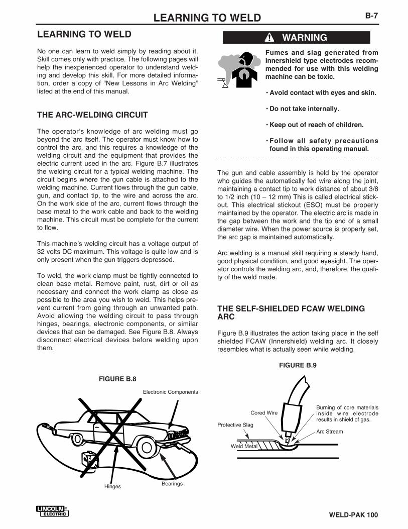
To weld, the work clamp must be tightly connected toclean base metal. Remove paint, rust, dirt or oil asnecessary and connect the work clamp as close aspossible to the area you wish to weld. This helps pre-vent current from going through an unwanted path.Avoid allowing the welding circuit to pass throughhinges, bearings, electronic components, or similardevices that can be damaged. See Figure B.8. Alwaysdisconnect electrical devices before welding uponthem.
Fumes and slag generated from
Innershield type electrodes recom-
mended for use with this welding
machine can be toxic.
• Avoid contact with eyes and skin.
• Do not take internally.
• Keep out of reach of children.
• Follow all safety precautions
found in this operating manual.
The gun and cable assembly is held by the operatorwho guides the automatically fed wire along the joint,maintaining a contact tip to work distance of about 3/8to 1/2 inch (10 – 12 mm) This is called electrical stick-out. This electrical stickout (ESO) must be properlymaintained by the operator. The electric arc is made inthe gap between the work and the tip end of a smalldiameter wire. When the power source is properly set,the arc gap is maintained automatically.
Arc welding is a manual skill requiring a steady hand,good physical condition, and good eyesight. The oper-ator controls the welding arc, and, therefore, the quali-ty of the weld made.
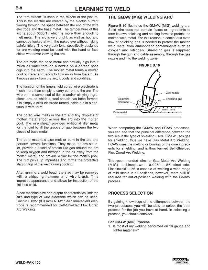
THE SELF-SHIELDED FCAW WELDINGARC
Figure B.9 illustrates the action taking place in the selfshielded FCAW (Innershield) welding arc. It closelyresembles what is actually seen while welding.
FIGURE B.9
WARNING
FIGURE B.8
Electronic Components
Hinges
Burning of core materialsinside wire electroderesults in shield of gas.
Arc Stream
Cored Wire
Protective Slag
Weld Metal
Bearings
WELD-PAK 100
B-8 LEARNING TO WELD
The “arc stream” is seen in the middle of the picture.This is the electric arc created by the electric currentflowing through the space between the end of the wireelectrode and the base metal. The temperature of thisarc is about 6000°F, which is more than enough tomelt metal. The arc is very bright, as well as hot, andcannot be looked at with the naked eye without riskingpainful injury. The very dark lens, specifically designedfor arc welding must be used with the hand or faceshield whenever viewing the arc.
The arc melts the base metal and actually digs into itmuch as water through a nozzle on a garden hosedigs into the earth. The molten metal forms a moltenpool or crater and tends to flow away from the arc. Asit moves away from the arc, it cools and solidifies.
The function of the Innershield cored wire electrode ismuch more than simply to carry current to the arc. Thewire core is composed of fluxes and/or alloying ingre-dients around which a steel sheath has been formed.It is simply a stick electrode turned inside out in a con-tinuous wire form.
The cored wire melts in the arc and tiny droplets ofmolten metal shoot across the arc into the moltenpool. The wire sheath provides additional filler metalfor the joint to fill the groove or gap between the twopieces of base metal.
The core materials also melt or burn in the arc andperform several functions. They make the arc stead-ier, provide a shield of smoke-like gas around the arcto keep oxygen and nitrogen in the air away from themolten metal, and provide a flux for the molten pool.The flux picks up impurities and forms the protectiveslag on top of the weld during cooling.
After running a weld bead, the slag may be removedwith a chipping hammer and wire brush. Thisimproves appearance and allows for inspection of thefinished weld.
Since machine size and output characteristics limit thesize and type of wire electrode which can be used,Lincoln 0.035ʼ (0.9 mm) NR-211-MP Innershield elec-trode is recommended for Self-Shielded Flux CoredArc Welding.
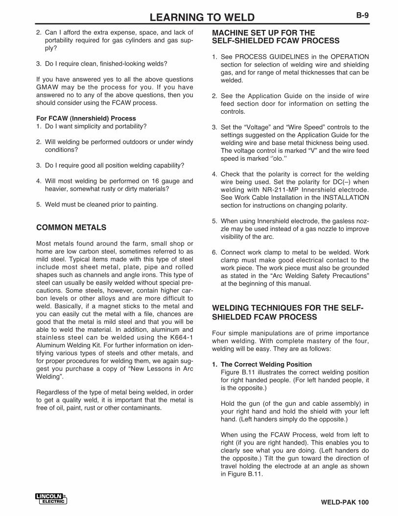
THE GMAW (MIG) WELDING ARC
Figure B.10 illustrates the GMAW (MIG) welding arc.Solid wire does not contain fluxes or ingredients toform its own shielding and no slag forms to protect themolten weld metal. For this reason, a continuous evenflow of shielding gas is needed to protect the moltenweld metal from atmospheric contaminants such asoxygen and nitrogen. Shielding gas is suppliedthrough the gun and cable assembly, through the gasnozzle and into the welding zone.
When comparing the GMAW and FCAW processes,you can see that the principal difference between thetwo lies in the type of shielding used. GMAW uses gasfor shielding, thus we have Gas Metal Arc Welding.FCAW uses the melting or burning of the core ingredi-ents for shielding, and is thus termed Self-ShieldedFlux Cored Arc Welding.
The recommended wire for Gas Metal Arc Welding(MIG) is Lincolnweld 0.025” L-56 electrode.Lincolnweld” L-56 is capable of welding a wide rangeof mild steels in all positions, however, more skill ISrequired for out-of-position welding with the GMAWprocess.
PROCESS SELECTION
By gaining knowledge of the differences between thetwo processes, you will be able to select the bestprocess for the job you have at hand. In selecting aprocess, you should consider:
For GMAW (MIG) Process
1. Is most of my welding performed on 16 gauge andlighter materials?
FIGURE B.10
Gas nozzle
Shielding gasSolid wireelectrode
Base metalWeld metal
WELD-PAK 100
B-9LEARNING TO WELD
2. Can I afford the extra expense, space, and lack ofportability required for gas cylinders and gas sup-ply?
3. Do I require clean, finished-looking welds?
If you have answered yes to all the above questionsGMAW may be the process for you. If you haveanswered no to any of the above questions, then youshould consider using the FCAW process.
For FCAW (Innershield) Process
1. Do I want simplicity and portability?
2. Will welding be performed outdoors or under windyconditions?
3. Do I require good all position welding capability?
4. Will most welding be performed on 16 gauge andheavier, somewhat rusty or dirty materials?
5. Weld must be cleaned prior to painting.
COMMON METALS
Most metals found around the farm, small shop orhome are low carbon steel, sometimes referred to asmild steel. Typical items made with this type of steelinclude most sheet metal, plate, pipe and rolledshapes such as channels and angle irons. This type ofsteel can usually be easily welded without special pre-cautions. Some steels, however, contain higher car-bon levels or other alloys and are more difficult toweld. Basically, if a magnet sticks to the metal andyou can easily cut the metal with a file, chances aregood that the metal is mild steel and that you will beable to weld the material. In addition, aluminum andstainless steel can be welded using the K664-1Aluminum Welding Kit. For further information on iden-tifying various types of steels and other metals, andfor proper procedures for welding them, we again sug-gest you purchase a copy of “New Lessons in ArcWelding”.
Regardless of the type of metal being welded, in orderto get a quality weld, it is important that the metal isfree of oil, paint, rust or other contaminants.
MACHINE SET UP FOR THESELF-SHIELDED FCAW PROCESS
1. See PROCESS GUIDELINES in the OPERATIONsection for selection of welding wire and shieldinggas, and for range of metal thicknesses that can bewelded.
2. See the Application Guide on the inside of wirefeed section door for information on setting thecontrols.
3. Set the “Voltage” and “Wire Speed” controls to thesettings suggested on the Application Guide for thewelding wire and base metal thickness being used.The voltage control is marked “V” and the wire feedspeed is marked ʻʼolo.ʼʼ
4. Check that the polarity is correct for the weldingwire being used. Set the polarity for DC(–) whenwelding with NR-211-MP Innershield electrode.See Work Cable Installation in the INSTALLATIONsection for instructions on changing polarity.
5. When using Innershield electrode, the gasless noz-zle may be used instead of a gas nozzle to improvevisibility of the arc.
6. Connect work clamp to metal to be welded. Workclamp must make good electrical contact to thework piece. The work piece must also be groundedas stated in the “Arc Welding Safety Precautions”at the beginning of this manual.
WELDING TECHNIQUES FOR THE SELF-SHIELDED FCAW PROCESS
Four simple manipulations are of prime importancewhen welding. With complete mastery of the four,welding will be easy. They are as follows:
1. The Correct Welding Position
Figure B.11 illustrates the correct welding positionfor right handed people. (For left handed people, itis the opposite.)
Hold the gun (of the gun and cable assembly) inyour right hand and hold the shield with your lefthand. (Left handers simply do the opposite.)
When using the FCAW Process, weld from left toright (if you are right handed). This enables you toclearly see what you are doing. (Left handers dothe opposite.) Tilt the gun toward the direction oftravel holding the electrode at an angle as shownin Figure B.11.
WELD-PAK 100
B-10 LEARNING TO WELD
ARC RAYS can burn eyes and skin.
When using an open arc process, it
Is necessary to use correct eye,
head and body protection.
Protect yourself and others, read
“ARC RAYS can burn” at the front
of this manual.
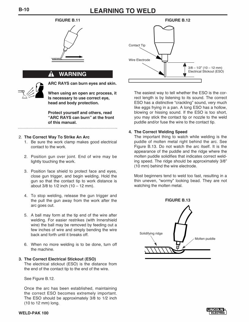
2. The Correct Way To Strike An Arc
1. Be sure the work clamp makes good electricalcontact to the work.
2. Position gun over joint. End of wire may belightly touching the work.
3. Position face shield to protect face and eyes,close gun trigger, and begin welding. Hold thegun so that the contact tip to work distance isabout 3/8 to 1/2 inch (10 – 12 mm).
4. To stop welding, release the gun trigger andthe pull the gun away from the work after thearc goes out.
5. A ball may form at the tip end of the wire afterwelding. For easier restrikes (with Innershieldwire) the ball may be removed by feeding out afew inches of wire and simply bending the wireback and forth until it breaks off.
6. When no more welding is to be done, turn offthe machine.
3. The Correct Electrical Stickout (ESO)
The electrical stickout (ESO) is the distance fromthe end of the contact tip to the end of the wire.
See Figure B.12.
Once the arc has been established, maintainingthe correct ESO becomes extremely important.The ESO should be approximately 3/8 to 1/2 inch(10 to 12 mm) long.
The easiest way to tell whether the ESO is the cor-rect length is by listening to its sound. The correctESO has a distinctive “crackling” sound, very muchlike eggs frying in a pan. A long ESO has a hollow,blowing or hissing sound. If the ESO is too short,you may stick the contact tip or nozzle to the weldpuddle and/or fuse the wire to the contact tip.
4. The Correct Welding Speed
The important thing to watch while welding is thepuddle of molten metal right behind the arc. SeeFigure B.13. Do not watch the arc itself. It is theappearance of the puddle and the ridge where themolten puddle solidifies that indicates correct weld-ing speed. The ridge should be approximately 3/8”(10 mm) behind the wire electrode.
Most beginners tend to weld too fast, resulting in athin uneven, “wormy” looking bead. They are notwatching the molten metal.
FIGURE B.13
FIGURE B.11 FIGURE B.12
WARNING
3/8 – 1/2” (10 – 12 mm)Electrical Stickout (ESO)
Contact Tip
Wire Electrode
Solidifying ridge
Molten puddle
WELD-PAK 100
B-11LEARNING TO WELD
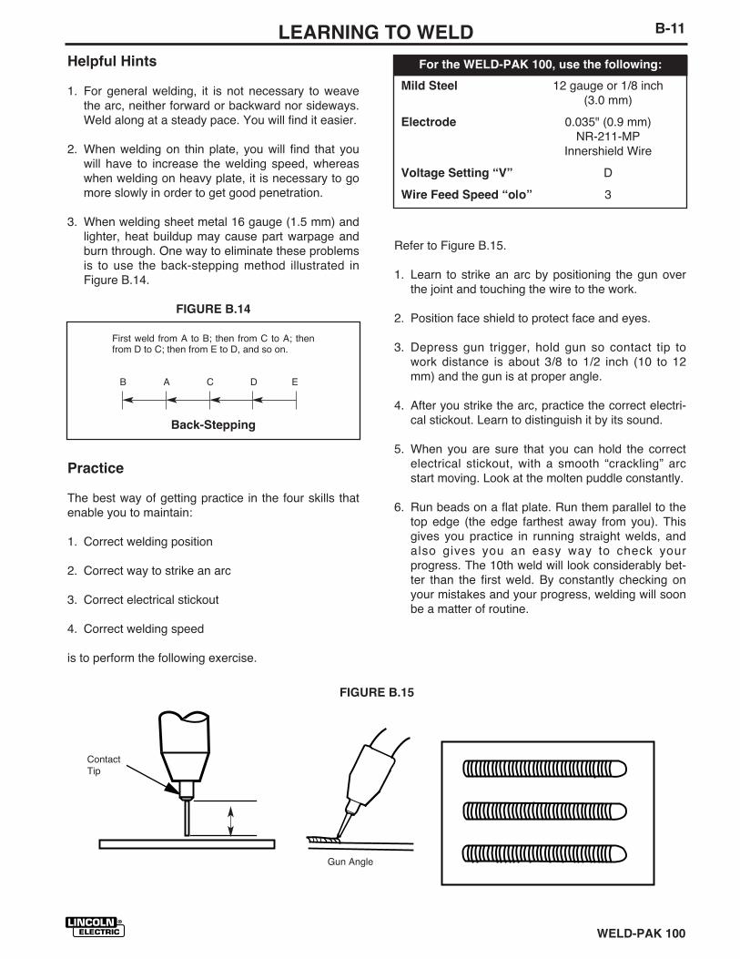
Helpful Hints
1. For general welding, it is not necessary to weavethe arc, neither forward or backward nor sideways.Weld along at a steady pace. You will find it easier.
2. When welding on thin plate, you will find that youwill have to increase the welding speed, whereaswhen welding on heavy plate, it is necessary to gomore slowly in order to get good penetration.
3. When welding sheet metal 16 gauge (1.5 mm) andlighter, heat buildup may cause part warpage andburn through. One way to eliminate these problemsis to use the back-stepping method illustrated inFigure B.14.
FIGURE B.14
Practice
The best way of getting practice in the four skills thatenable you to maintain:
1. Correct welding position
2. Correct way to strike an arc
3. Correct electrical stickout
4. Correct welding speed
is to perform the following exercise.
Refer to Figure B.15.
1. Learn to strike an arc by positioning the gun overthe joint and touching the wire to the work.
2. Position face shield to protect face and eyes.
3. Depress gun trigger, hold gun so contact tip towork distance is about 3/8 to 1/2 inch (10 to 12mm) and the gun is at proper angle.
4. After you strike the arc, practice the correct electri-cal stickout. Learn to distinguish it by its sound.
5. When you are sure that you can hold the correctelectrical stickout, with a smooth “crackling” arcstart moving. Look at the molten puddle constantly.
6. Run beads on a flat plate. Run them parallel to thetop edge (the edge farthest away from you). Thisgives you practice in running straight welds, andalso gives you an easy way to check yourprogress. The 10th weld will look considerably bet-ter than the first weld. By constantly checking onyour mistakes and your progress, welding will soonbe a matter of routine.
First weld from A to B; then from C to A; thenfrom D to C; then from E to D, and so on.
B A C D E
Back-Stepping
FIGURE B.15
ContactTip
Gun Angle
Mild Steel 12 gauge or 1/8 inch(3.0 mm)
Electrode 0.035" (0.9 mm)NR-211-MP
Innershield Wire
Voltage Setting “V” D
Wire Feed Speed “o|o” 3
For the WELD-PAK 100, use the following:
WELD-PAK 100
B-12 LEARNING TO WELD
MACHINE SET UP FOR THE GMAW (MIG)PROCESS
1. See PROCESS GUIDELINES in the OPERATIONsection for selection of welding wire and shieldinggas, and for range of metal thicknesses that canbe welded.
2. See the Application Guide on the inside of wirefeed section door for information on setting thecontrols.
3. Set the “Voltage” and “Wire Speed” controls to thesettings suggested on the Application Guide for thewelding wire and base metal thickness being used.The voltage control is marked “V” and the wirefeed speed is marked ʻʼolo.ʼʼ
4. Check that the polarity is correct for the weldingwire being used. Set the polarity for DC(+) whenwelding with the GMAW (MIG) process. See WorkCable Installation in the INSTALLATION sectionfor instructions for changing polarity.
5. Check that the gas nozzle and proper size linerand contact tip are being used and that the gassupply is turned on. If adjustable, set for 15 to 20cubic feet per hour (7 to 10 l/min.) under normalconditions, increase to as high as 35 CFH (17I/min.) under drafty (slightly windy) conditions.
6. Connect work clamp to metal to be welded. Workclamp must make good electrical contact to thework piece. The work piece must also be groundedas stated in the “Arc Welding Safety Precautions”at the beginning of this manual.
WELDING TECHNIQUES FOR THE GMAW(MIG) PROCESS
Four simple manipulations are of prime importancewhen welding. With complete mastery of the four,welding will be easy. They are as follows:
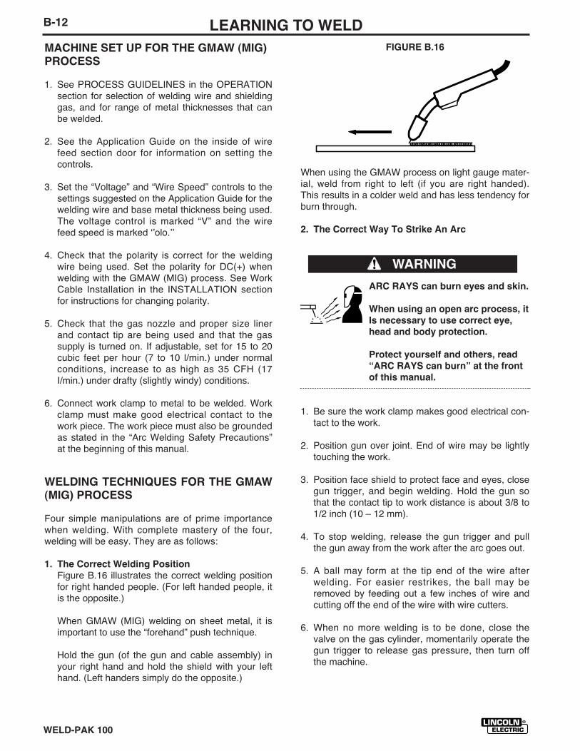
1. The Correct Welding Position
Figure B.16 illustrates the correct welding positionfor right handed people. (For left handed people, itis the opposite.)
When GMAW (MIG) welding on sheet metal, it isimportant to use the “forehand” push technique.
Hold the gun (of the gun and cable assembly) inyour right hand and hold the shield with your lefthand. (Left handers simply do the opposite.)
FIGURE B.16
When using the GMAW process on light gauge mater-ial, weld from right to left (if you are right handed).This results in a colder weld and has less tendency forburn through.
2. The Correct Way To Strike An Arc
ARC RAYS can burn eyes and skin.
When using an open arc process, it
Is necessary to use correct eye,
head and body protection.
Protect yourself and others, read
“ARC RAYS can burn” at the front
of this manual.
1. Be sure the work clamp makes good electrical con-tact to the work.
2. Position gun over joint. End of wire may be lightlytouching the work.
3. Position face shield to protect face and eyes, closegun trigger, and begin welding. Hold the gun sothat the contact tip to work distance is about 3/8 to1/2 inch (10 – 12 mm).
4. To stop welding, release the gun trigger and pullthe gun away from the work after the arc goes out.
5. A ball may form at the tip end of the wire afterwelding. For easier restrikes, the ball may beremoved by feeding out a few inches of wire andcutting off the end of the wire with wire cutters.
6. When no more welding is to be done, close thevalve on the gas cylinder, momentarily operate thegun trigger to release gas pressure, then turn offthe machine.
WARNING
WELD-PAK 100
B-13LEARNING TO WELD
FIGURE B.17
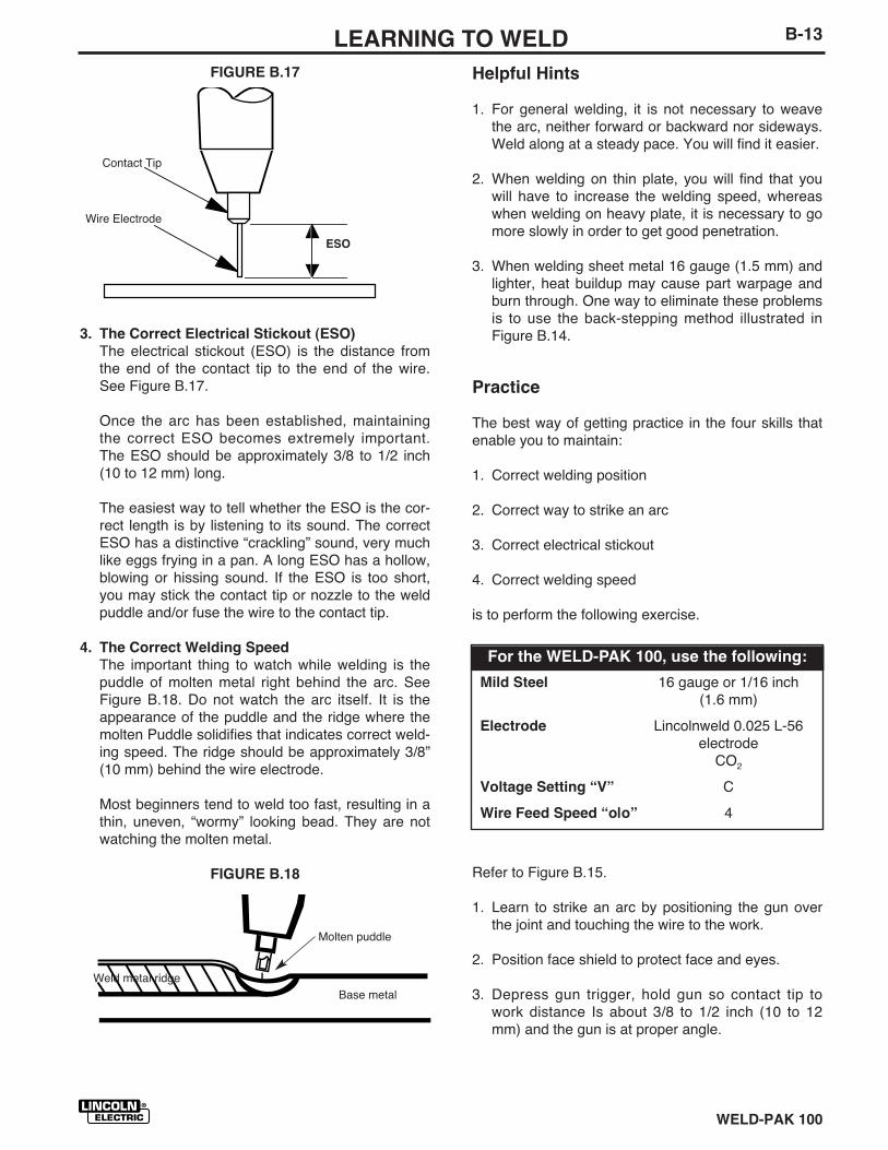
3. The Correct Electrical Stickout (ESO)
The electrical stickout (ESO) is the distance fromthe end of the contact tip to the end of the wire.See Figure B.17.
Once the arc has been established, maintainingthe correct ESO becomes extremely important.The ESO should be approximately 3/8 to 1/2 inch(10 to 12 mm) long.
The easiest way to tell whether the ESO is the cor-rect length is by listening to its sound. The correctESO has a distinctive “crackling” sound, very muchlike eggs frying in a pan. A long ESO has a hollow,blowing or hissing sound. If the ESO is too short,you may stick the contact tip or nozzle to the weldpuddle and/or fuse the wire to the contact tip.
4. The Correct Welding Speed
The important thing to watch while welding is thepuddle of molten metal right behind the arc. SeeFigure B.18. Do not watch the arc itself. It is theappearance of the puddle and the ridge where themolten Puddle solidifies that indicates correct weld-ing speed. The ridge should be approximately 3/8”(10 mm) behind the wire electrode.
Most beginners tend to weld too fast, resulting in athin, uneven, “wormy” looking bead. They are notwatching the molten metal.
FIGURE B.18
Helpful Hints
1. For general welding, it is not necessary to weavethe arc, neither forward or backward nor sideways.Weld along at a steady pace. You will find it easier.
2. When welding on thin plate, you will find that youwill have to increase the welding speed, whereaswhen welding on heavy plate, it is necessary to gomore slowly in order to get good penetration.
3. When welding sheet metal 16 gauge (1.5 mm) andlighter, heat buildup may cause part warpage andburn through. One way to eliminate these problemsis to use the back-stepping method illustrated inFigure B.14.
Practice
The best way of getting practice in the four skills thatenable you to maintain:
1. Correct welding position
2. Correct way to strike an arc
3. Correct electrical stickout
4. Correct welding speed
is to perform the following exercise.
Refer to Figure B.15.
1. Learn to strike an arc by positioning the gun overthe joint and touching the wire to the work.
2. Position face shield to protect face and eyes.
3. Depress gun trigger, hold gun so contact tip towork distance Is about 3/8 to 1/2 inch (10 to 12mm) and the gun is at proper angle.
Contact Tip
Wire Electrode
ESO
Molten puddle
Base metalWeld metal ridge
Mild Steel 16 gauge or 1/16 inch(1.6 mm)
Electrode Lincolnweld 0.025 L-56electrode
CO2
Voltage Setting “V” C
Wire Feed Speed “o|o” 4
For the WELD-PAK 100, use the following:
WELD-PAK 100
B-14 LEARNING TO WELD
4. After you strike the arc, practice the correct electri-cal stickout. Learn to distinguish it by its sound.
5. When you are sure that you can hold the correctelectrical stickout, with a smooth “crackling” arc,start moving. Look at the molten puddle constantly,
6. Run beads on a flat plate. Run them parallel to thetop edge (the edge farthest away from you). Thisgives you practice in running straight welds, andalso gives you an easy way to check yourprogress. The 10th weld will look considerably bet-ter than the first weld. By constantly checking onyour mistakes and your progress, welding will soonbe a matter of routine.
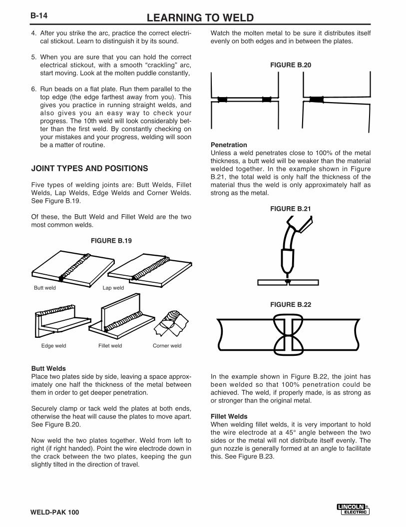
JOINT TYPES AND POSITIONS
Five types of welding joints are: Butt Welds, FilletWelds, Lap Welds, Edge Welds and Corner Welds.See Figure B.19.
Of these, the Butt Weld and Fillet Weld are the twomost common welds.
FIGURE B.19
Butt Welds
Place two plates side by side, leaving a space approx-imately one half the thickness of the metal betweenthem in order to get deeper penetration.
Securely clamp or tack weld the plates at both ends,otherwise the heat will cause the plates to move apart.See Figure B.20.
Now weld the two plates together. Weld from left toright (if right handed). Point the wire electrode down inthe crack between the two plates, keeping the gunslightly tilted in the direction of travel.
Watch the molten metal to be sure it distributes itselfevenly on both edges and in between the plates.
FIGURE B.20
Penetration
Unless a weld penetrates close to 100% of the metalthickness, a butt weld will be weaker than the materialwelded together. In the example shown in FigureB.21, the total weld is only half the thickness of thematerial thus the weld is only approximately half asstrong as the metal.
FIGURE B.21
FIGURE B.22
In the example shown in Figure B.22, the joint hasbeen welded so that 100% penetration could beachieved. The weld, if properly made, is as strong asor stronger than the original metal.
Fillet Welds
When welding fillet welds, it is very important to holdthe wire electrode at a 45° angle between the twosides or the metal will not distribute itself evenly. Thegun nozzle is generally formed at an angle to facilitatethis. See Figure B.23.
Butt weld Lap weld
Edge weld Fillet weld Corner weld
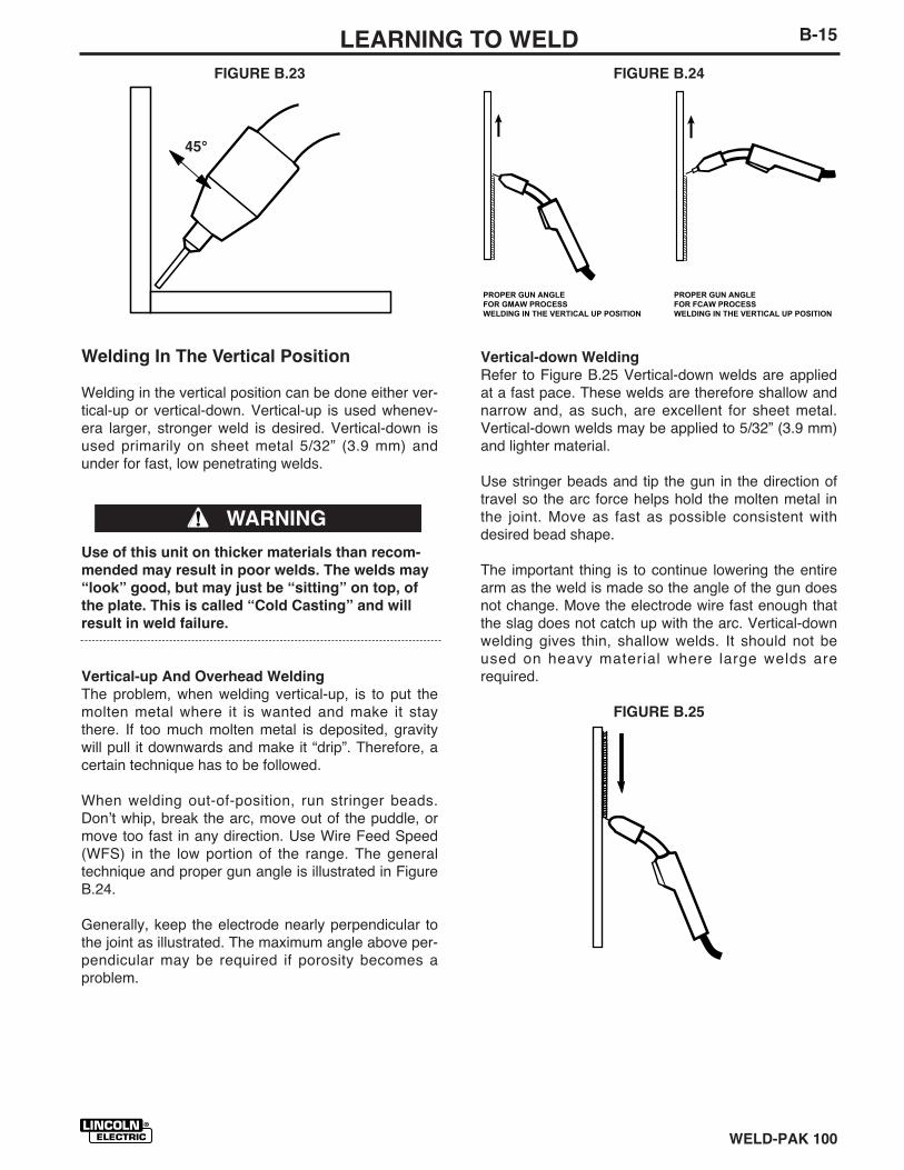
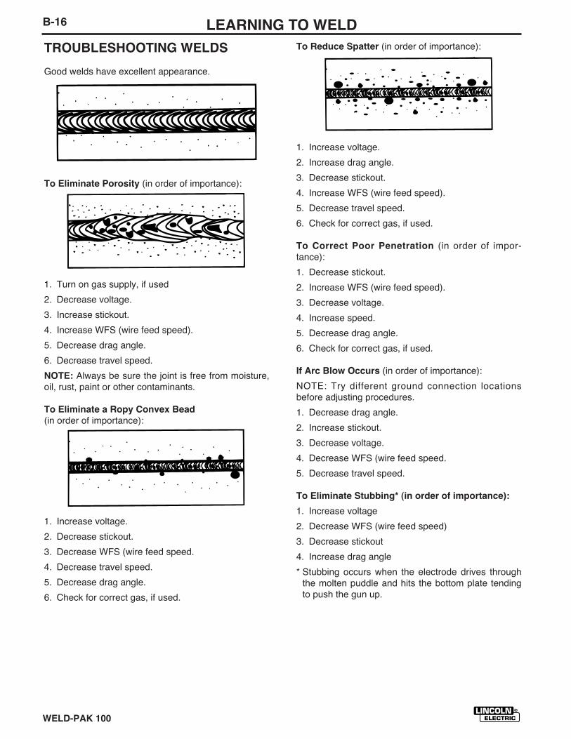
FIGURE B.24
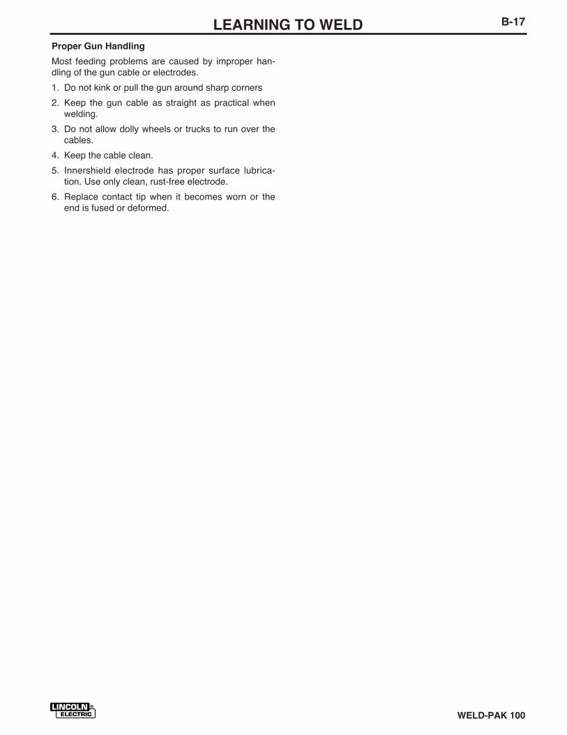
Vertical-down Welding
Refer to Figure B.25 Vertical-down welds are appliedat a fast pace. These welds are therefore shallow andnarrow and, as such, are excellent for sheet metal.Vertical-down welds may be applied to 5/32” (3.9 mm)and lighter material.
Use stringer beads and tip the gun in the direction oftravel so the arc force helps hold the molten metal inthe joint. Move as fast as possible consistent withdesired bead shape.
The important thing is to continue lowering the entirearm as the weld is made so the angle of the gun doesnot change. Move the electrode wire fast enough thatthe slag does not catch up with the arc. Vertical-downwelding gives thin, shallow welds. It should not beused on heavy material where large welds arerequired.
FIGURE B.25
PROPER GUN ANGLE FOR GMAW PROCESS WELDING IN THE VERTICAL UP POSITION
PROPER GUN ANGLE FOR FCAW PROCESS WELDING IN THE VERTICAL UP POSITION
WELD-PAK 100
B-15LEARNING TO WELD
FIGURE B.23
Welding In The Vertical Position
Welding in the vertical position can be done either ver-tical-up or vertical-down. Vertical-up is used whenev-era larger, stronger weld is desired. Vertical-down isused primarily on sheet metal 5/32” (3.9 mm) andunder for fast, low penetrating welds.
Use of this unit on thicker materials than recom-
mended may result in poor welds. The welds may
“look” good, but may just be “sitting” on top, of
the plate. This is called “Cold Casting” and will
result in weld failure.
Vertical-up And Overhead Welding
The problem, when welding vertical-up, is to put themolten metal where it is wanted and make it staythere. If too much molten metal is deposited, gravitywill pull it downwards and make it “drip”. Therefore, acertain technique has to be followed.
When welding out-of-position, run stringer beads.Donʼt whip, break the arc, move out of the puddle, ormove too fast in any direction. Use Wire Feed Speed(WFS) in the low portion of the range. The generaltechnique and proper gun angle is illustrated in FigureB.24.
Generally, keep the electrode nearly perpendicular tothe joint as illustrated. The maximum angle above per-pendicular may be required if porosity becomes aproblem.
45°
WARNING
WELD-PAK 100
B-16 LEARNING TO WELD
TROUBLESHOOTING WELDS
Good welds have excellent appearance.
To Eliminate Porosity (in order of importance):
1. Turn on gas supply, if used
2. Decrease voltage.
3. Increase stickout.
4. Increase WFS (wire feed speed).
5. Decrease drag angle.
6. Decrease travel speed.
NOTE: Always be sure the joint is free from moisture,oil, rust, paint or other contaminants.
To Eliminate a Ropy Convex Bead
(in order of importance):
1. Increase voltage.
2. Decrease stickout.
3. Decrease WFS (wire feed speed.
4. Decrease travel speed.
5. Decrease drag angle.
6. Check for correct gas, if used.
To Reduce Spatter (in order of importance):
1. Increase voltage.
2. Increase drag angle.
3. Decrease stickout.
4. Increase WFS (wire feed speed).
5. Decrease travel speed.
6. Check for correct gas, if used.
To Correct Poor Penetration (in order of impor-tance):
1. Decrease stickout.
2. Increase WFS (wire feed speed).
3. Decrease voltage.
4. Increase speed.
5. Decrease drag angle.
6. Check for correct gas, if used.
If Arc Blow Occurs (in order of importance):
NOTE: Try different ground connection locationsbefore adjusting procedures.
1. Decrease drag angle.
2. Increase stickout.
3. Decrease voltage.
4. Decrease WFS (wire feed speed.
5. Decrease travel speed.
To Eliminate Stubbing* (in order of importance):
1. Increase voltage
2. Decrease WFS (wire feed speed)
3. Decrease stickout
4. Increase drag angle
* Stubbing occurs when the electrode drives throughthe molten puddle and hits the bottom plate tendingto push the gun up.
WELD-PAK 100
B-17LEARNING TO WELD
Proper Gun Handling
Most feeding problems are caused by improper han-dling of the gun cable or electrodes.
1. Do not kink or pull the gun around sharp corners
2. Keep the gun cable as straight as practical whenwelding.
3. Do not allow dolly wheels or trucks to run over thecables.
4. Keep the cable clean.
5. Innershield electrode has proper surface lubrica-tion. Use only clean, rust-free electrode.
6. Replace contact tip when it becomes worn or theend is fused or deformed.
WELD-PAK 100
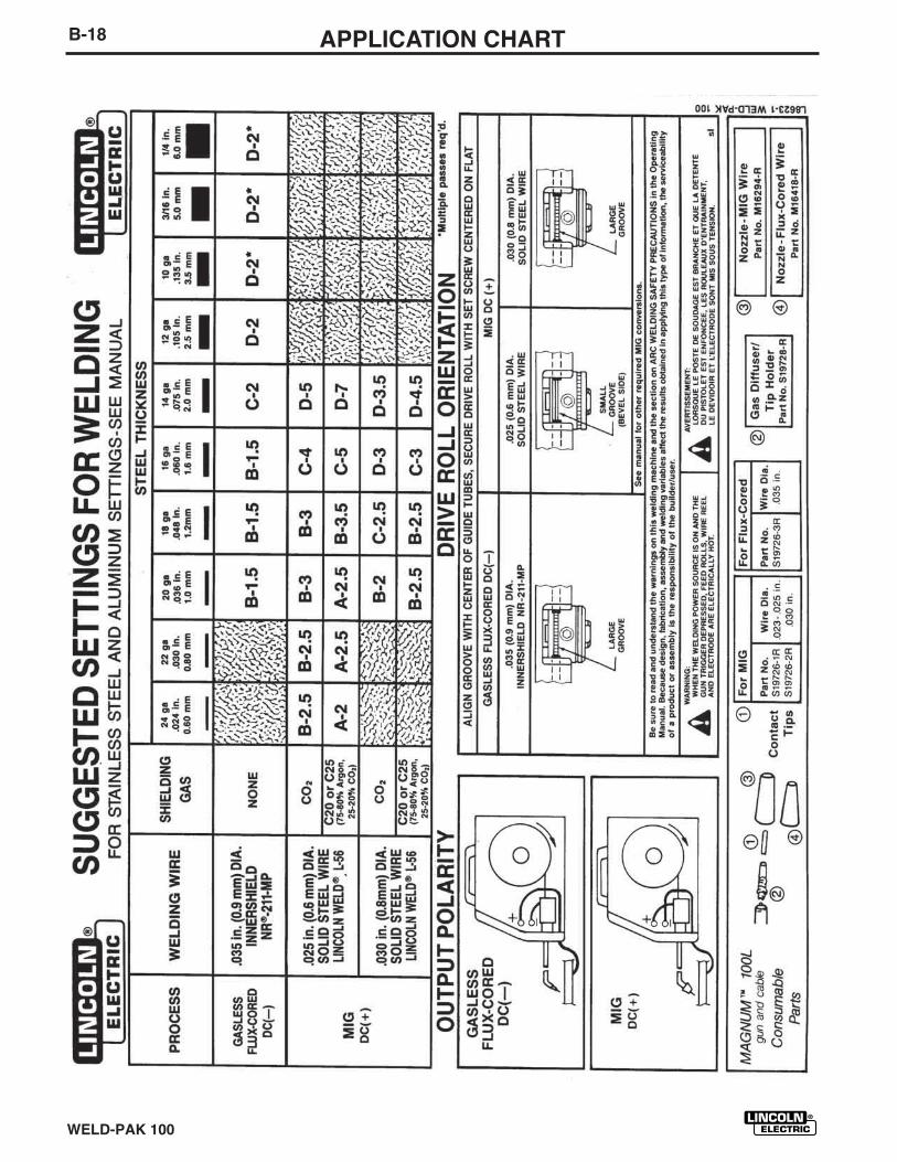
B-18 APPLICATION CHART
C-1ACCESSORIES
WELD-PAK 100
3. Change drive roll orientation (if required)for the wire size selected. See “ChangingDrive Roll” in Maintenance section fordetails.
4. Install the proper gun liner and tip for thewire size selected. See “ComponentReplacement” in Maintenance section fordetails.
5. Remove gasless nozzle (if installed) andinstall gas nozzle. To remove, simplyunscrew.
6. Load wire into machine and thread intogun and cable per “Welding WireLoading” section.
OPTIONAL ACCESSORIES
1. K520 Utility Cart — Designed to trans-port the Lincoln family of small welders.Has provisions for mounting a single gascylinder. Has front casters and large rearwheels. Handle height is easilyadjustable. Bottom tray provided for toolsand accessories. Easy assemblyrequired; takes less than 15 minutes.
2. K664-1 Aluminum Feeding Kit — Thiskit required for welding with .035Aluminum wire. This kit may also beused for feeding .035 stainless wire.Included with this kit are a drive roll, linerand contact tip. It is important when
changing between welding with steel
wire and aluminum to exchange these
components due to the lubricant
applied to steel wire. Failure to do so
may result in contaminated welds
when welding aluminum.
3. K610-1 MIG Conversion Kit for the
WELD-PAK 100 — Complete kit for usewith .025" (0.6 mm) electrode wire andeither CO2 or Argon-mixed gas. Includes.025-.030" (0.6-0.8 mm) cable liner, two.025" (0.6 mm) contact tips, gas nozzle,2 lb. spool of .025" (0.6 mm) L-56 elec-trode, gas regulator, gas hose, regulatoradapter for CO2 cylinders and gas sole-noid assembly, with all necessary hard-ware and easy instructions for installinggas solenoid. Use with .030" (0.8 mm)wire requires additional .030" (0.8 mm)contact tip and electrode wire.
MIG CONVERSION
Several changes are needed to convert theunit for operation with the MIG (GMAW)process. The K610-1 MIG Conversion Kitfor the WELD-PAK 100 includes all the nec-essary accessories for this conversion andis provided for this purpose. The followingconversions should be made using the con-tents of this kit:
1. Install the gas solenoid. Completeinstructions are included with the kit.
2. Change the output polarity to DC(+). See“Work Cable Installation” in Installationsection for details.

C-2 NOTES
WELD-PAK 100
D-1MAINTENANCE
WELD-PAK 100
MAINTENANCE
SAFETY PRECAUTIONS
ELECTRIC SHOCK can kill.
• Disconnect input power by removing
plug from receptacle before working
inside WELD-PAK 100. Use only ground-
ed receptacle. Do not touch electrically
“hot” parts inside WELD-PAK 100.
• Have qualified personnel do the mainte-
nance and trouble shooting work.
ROUTINE MAINTENANCE
POWER SOURCE COMPARTMENTNo user serviceable parts inside! Do not attempt to performservice in the power source (fixed) side of the WELD-PAK100. Take the unit to an authorized Lincoln Service Center ifyou experience problems. NO maintenance is required.
WIRE FEED COMPARTMENT
1. When necessary, vacuum accumulated dirt from gearboxand wire feed section.
2. Occasionally inspect the incoming guide tube and cleaninside diameter is necessary.
3. Motor and gearbox have lifetime lubrication and require nomaintenance.
FAN MOTOR
Has lifetime lubrication — requires no maintenance.
WIRE REEL SPINDLE
Requires no maintenance. Do not lubricate shaft.
WARNING
D-2 MAINTENANCE
WELD-PAK 100
5. To remove gun tube from gun, removegas nozzle or gasless nozzle andremove diffuser from gun tube. Removeboth collars from each end of the gunhandle and separate the handle halves.Loosen the locking nut holding the guntube in place against the gun end cableconnector. Unscrew gun tube from cableconnector. To install gun tube, screw thelocking nut on the gun tube as far aspossible. Then screw the gun tube intothe cable connector until it bottoms.Then unscrew (no more than one turn)the gun tube until its axis is perpendicu-lar to the flat sides of the cable connectorand pointed in the direction of the trigger.Tighten the locking nut so as to maintainthe proper relationship between the guntube and the cable connector. Replacethe gun handle, trigger and diffuser.Replace the gas nozzle or gasless noz-zle.
COMPONENTREPLACEMENTPROCEDURES
CHANGING THE CONTACT TIP
1. Refer to Figure D.2. Remove the gasnozzle from the gun by unscrewingcounter-clockwise.
2. Remove the existing contact tip from thegun by unscrewing counter-clockwise.
3. Insert and hand tighten desired contacttip.
4. Replace gas nozzle.
GUN AND CABLEMAINTENANCE
FOR MAGNUM™ 100L GUN
Gun Cable Cleaning
Clean cable liner after using approximately300 lbs (136 kg) of solid wire or 50 lbs (23kg) of flux-cored wire. Remove the cablefrom the wire feeder and lay it out straighton the floor. Remove the contact tip fromthe gun. Using low pressure air, gently blowout the cable liner from the gas diffuser end.
Excessive pressure at the start may
cause the dirt to form a plug.
Flex the cable over its entire length andagain blow out the cable. Repeat this proce-dure until no further dirt comes out.
Contact Tips, Nozzles, and Gun Tubes
1. Dirt can accumulate in the contact tiphole and restrict wire feeding. After eachspool of wire is used, remove the contacttip and clean it by pushing a short pieceof wire through the tip repeatedly. Usethe wire as a reamer to remove dirt thatmay be adhering to the wall of the holethrough the tip.
2. Replace worn contact tips as required. Avariable or “hunting” arc is a typicalsymptom of a worn contact tip. To installa new tip, choose the correct size con-tact tip for the electrode being used (wiresize is stenciled on the side of the con-tact tip) and screw it snugly into the gasdiffuser.
3. Remove spatter from inside of gas noz-zle and from tip after each 10 minutes ofarc time or as required.
4. Be sure the gas nozzle is fully screwedonto the diffuser for gas shieldedprocesses. For the Innershield® process,the gasless nozzle should be screwsonto the diffuser.
CAUTION
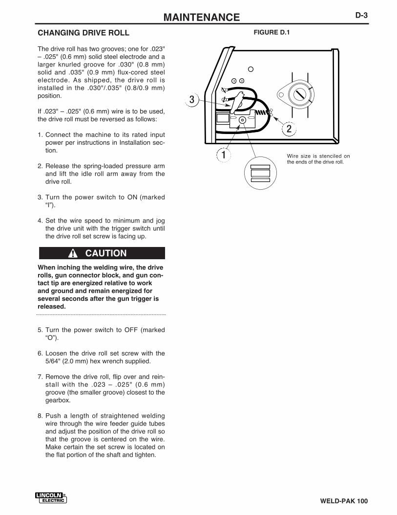
D-3MAINTENANCE
WELD-PAK 100
CHANGING DRIVE ROLL
The drive roll has two grooves; one for .023"– .025" (0.6 mm) solid steel electrode and alarger knurled groove for .030" (0.8 mm)solid and .035" (0.9 mm) flux-cored steelelectrode. As shipped, the drive roll isinstalled in the .030"/.035" (0.8/0.9 mm)position.
If .023" – .025" (0.6 mm) wire is to be used,the drive roll must be reversed as follows:
1. Connect the machine to its rated inputpower per instructions in Installation sec-tion.
2. Release the spring-loaded pressure armand lift the idle roll arm away from thedrive roll.
3. Turn the power switch to ON (marked“I”).
4. Set the wire speed to minimum and jogthe drive unit with the trigger switch untilthe drive roll set screw is facing up.
When inching the welding wire, the drive
rolls, gun connector block, and gun con-
tact tip are energized relative to work
and ground and remain energized for
several seconds after the gun trigger is
released.
5. Turn the power switch to OFF (marked“O”).
6. Loosen the drive roll set screw with the5/64" (2.0 mm) hex wrench supplied.
7. Remove the drive roll, flip over and rein-stall with the .023 – .025" (0.6 mm)groove (the smaller groove) closest to thegearbox.
8. Push a length of straightened weldingwire through the wire feeder guide tubesand adjust the position of the drive roll sothat the groove is centered on the wire.Make certain the set screw is located onthe flat portion of the shaft and tighten.
FIGURE D.1
Wire size is stenciled onthe ends of the drive roll.
3
2
1
CAUTION
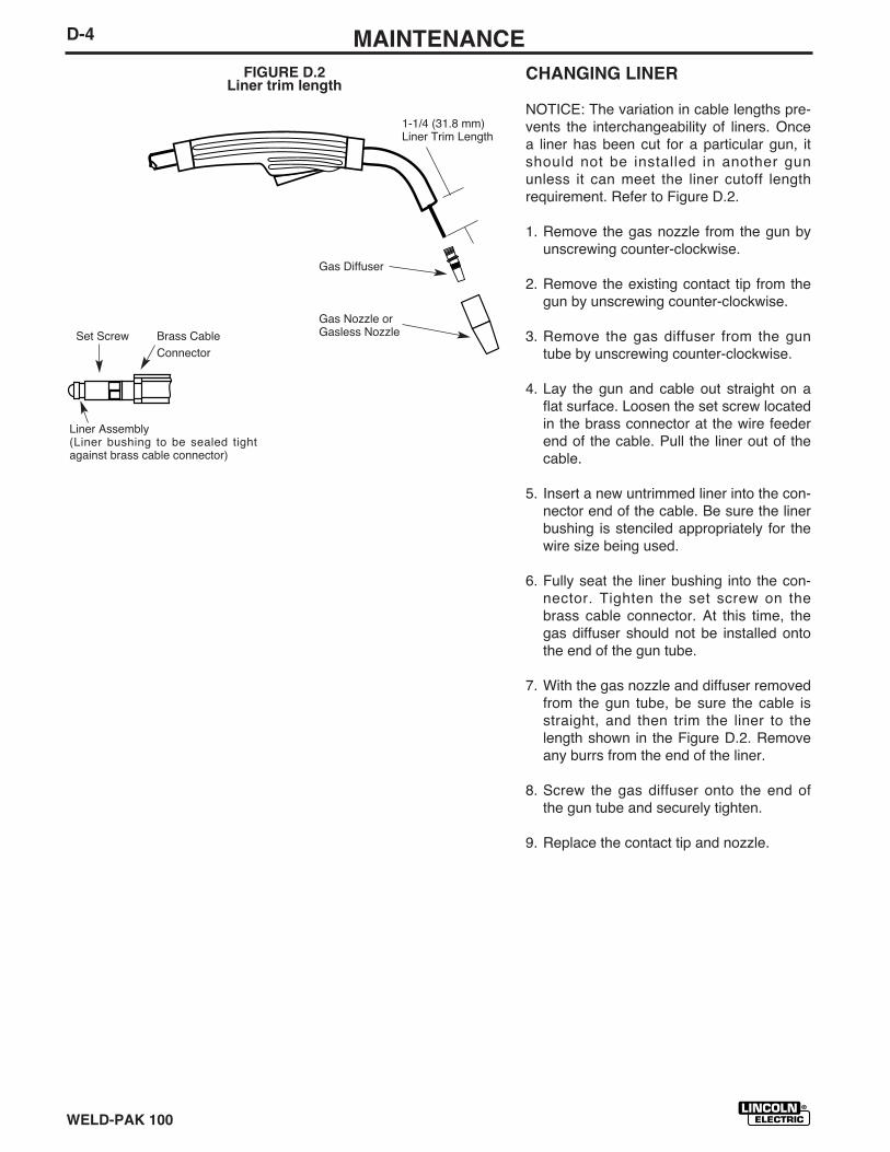
D-4 MAINTENANCE
WELD-PAK 100
CHANGING LINER
NOTICE: The variation in cable lengths pre-vents the interchangeability of liners. Oncea liner has been cut for a particular gun, itshould not be installed in another gununless it can meet the liner cutoff lengthrequirement. Refer to Figure D.2.
1. Remove the gas nozzle from the gun byunscrewing counter-clockwise.
2. Remove the existing contact tip from thegun by unscrewing counter-clockwise.
3. Remove the gas diffuser from the guntube by unscrewing counter-clockwise.
4. Lay the gun and cable out straight on aflat surface. Loosen the set screw locatedin the brass connector at the wire feederend of the cable. Pull the liner out of thecable.
5. Insert a new untrimmed liner into the con-nector end of the cable. Be sure the linerbushing is stenciled appropriately for thewire size being used.
6. Fully seat the liner bushing into the con-nector. Tighten the set screw on thebrass cable connector. At this time, thegas diffuser should not be installed ontothe end of the gun tube.
7. With the gas nozzle and diffuser removedfrom the gun tube, be sure the cable isstraight, and then trim the liner to thelength shown in the Figure D.2. Removeany burrs from the end of the liner.
8. Screw the gas diffuser onto the end ofthe gun tube and securely tighten.
9. Replace the contact tip and nozzle.
1-1/4 (31.8 mm)Liner Trim Length
Gas Diffuser
Gas Nozzle orGasless NozzleSet Screw Brass Cable
Connector
Liner Assembly(Liner bushing to be sealed tightagainst brass cable connector)
FIGURE D.2Liner trim length
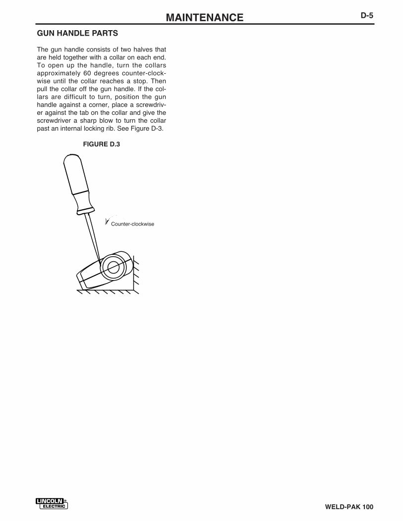
D-5MAINTENANCE
WELD-PAK 100
GUN HANDLE PARTS
The gun handle consists of two halves thatare held together with a collar on each end.To open up the handle, turn the collarsapproximately 60 degrees counter-clock-wise until the collar reaches a stop. Thenpull the collar off the gun handle. If the col-lars are difficult to turn, position the gunhandle against a corner, place a screwdriv-er against the tab on the collar and give thescrewdriver a sharp blow to turn the collarpast an internal locking rib. See Figure D-3.
FIGURE D.3
➣
Counter-clockwise

D-6 NOTES
WELD-PAK 100
E-1TROUBLESHOOTING
WELD-PAK 100
This Troubleshooting Guide is provided tohelp you locate and remedy possible prob-lems with machine setup or operation.Simply follow the three-step procedurelisted below.
Step 1. LOCATE PROBLEM (SYMPTOM).
Look under the column labeled “PROBLEM(SYMPTOMS)”. This column describes pos-sible symptoms that the machine mayexhibit. Find the listing that best describesthe symptom that the machine is exhibiting.
Symptoms are grouped into three main cat-egories: output problems, function prob-lems, welding problems.
Step 2. PERFORM EXTERNAL TESTS.
The second column labeled “POSSIBLEAREAS OF MISADJUSTMENT(S)” lists theobvious external possibilities that may con-tribute to the machine symptom. Performthese tests/checks in the order listed. Ingeneral, these tests can be conducted with-out removing the case wrap-around cover.
Step 3. PERFORM COMPONENT TESTS.If you have exhausted all of the recom-mended tests in Step 2, Consult your LocalAuthorized Field Service Facility.
HOW TO USE TROUBLESHOOTING GUIDE
Service and Repair should only be performed by Lincoln Electric Factory Trained Personnel.Unauthorized repairs performed on this equipment may result in danger to the technician andmachine operator and will invalidate your factory warranty. For your safety and to avoidElectrical Shock, please observe all safety notes and precautions detailed throughout thismanual.__________________________________________________________________________
WARNING
If for any reason you do not understand the test procedures or are unable to performthe tests/repairs safely, contact your LOCAL AUTHORIZED LINCOLN ELECTRIC
FIELD SERVICE FACILITY for assistance before you proceed._____________________________________________________________________
CAUTION
E-2 TROUBLESHOOTING
WELD-PAK 100
Observe Safety Guidelinesdetailed in the beginning of this manual.
TROUBLESHOOTING GUIDE
PROBLEMS
(SYMPTOMS)
Major physical or electrical damageis evident.
No wire feed, weld output or gasflow when gun trigger is pulled. Fandoes NOT operate.
No wire feed, weld output or gasflow when gun trigger is pulled Fanoperates normally.
POSSIBLE AREAS OF
MISADJUSTMENT(S)
NoneContact your local Authorized FieldService Facility.
1. Make sure correct voltage isapplied to the machine (115vac).
2. Make certain that power switchis in the ON position.
3. Make sure circuit breaker insidewire drive compartment is reset.
1. The thermostat may be trippeddue to overheating. Let machinecool. Weld at lower duty cycle.
2. Check for obstructions in airflow. Check Gun Trigger connec-tions. See Installation section.
3. Gun trigger may be faulty.
RECOMMENDED
COURSE OF ACTION
Contact your local LincolnAuthorized Field Service Facility.
OUTPUT PROBLEMS
If for any reason you do not understand the test procedures or are unable to perform the tests/repairs safely, contact yourLOCAL AUTHORIZED LINCOLN ELECTRIC FIELD SERVICE FACILITY for assistance before you proceed.
CAUTION
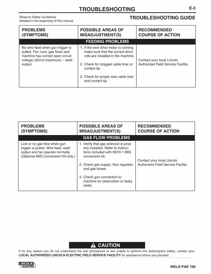
E-3TROUBLESHOOTING
WELD-PAK 100
TROUBLESHOOTING GUIDEObserve Safety Guidelinesdetailed in the beginning of this manual.
PROBLEMS
(SYMPTOMS)
No wire feed when gun trigger ispulled. Fan runs, gas flows andmachine has correct open circuitvoltage (32vcd maximum) – weldoutput.
POSSIBLE AREAS OF
MISADJUSTMENT(S)
1. If the wire drive motor is runningmake sure that the correct driverolls are installed in the machine.
2. Check for clogged cable liner orcontact tip.
3. Check for proper size cable linerand contact tip.
RECOMMENDED
COURSE OF ACTION
Contact your local LincolnAuthorized Field Service Facility.
FEEDING PROBLEMS
If for any reason you do not understand the test procedures or are unable to perform the tests/repairs safely, contact yourLOCAL AUTHORIZED LINCOLN ELECTRIC FIELD SERVICE FACILITY for assistance before you proceed.
CAUTION
PROBLEMS
(SYMPTOMS)
Low or no gas flow when guntrigger is pulled. Wire feed, weldoutput and fan operate normally.(Optional MIG Conversion Kit only.)
POSSIBLE AREAS OF
MISADJUSTMENT(S)
1. Verify that gas solenoid is prop-erly installed. Refer to instruc-tions included with K610-1 MIGconversion kit.
2. Check gas supply, flow regulatorand gas hoses.
3. Check gun connection tomachine for obstruction or leakyseals.
RECOMMENDED
COURSE OF ACTION
Contact your local LincolnAuthorized Field Service Facility.
GAS FLOW PROBLEMS
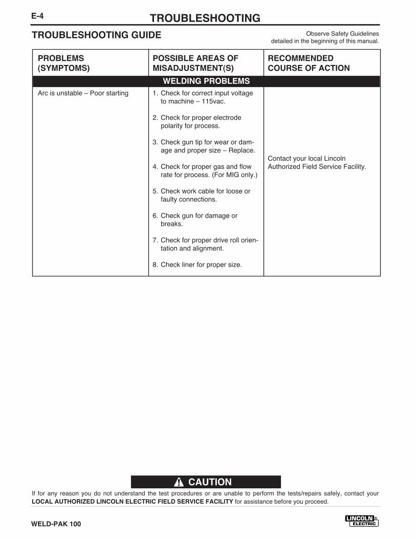
E-4 TROUBLESHOOTING
WELD-PAK 100
Observe Safety Guidelinesdetailed in the beginning of this manual.
TROUBLESHOOTING GUIDE
If for any reason you do not understand the test procedures or are unable to perform the tests/repairs safely, contact yourLOCAL AUTHORIZED LINCOLN ELECTRIC FIELD SERVICE FACILITY for assistance before you proceed.
CAUTION
PROBLEMS
(SYMPTOMS)
Arc is unstable – Poor starting
POSSIBLE AREAS OF
MISADJUSTMENT(S)
1. Check for correct input voltageto machine – 115vac.
2. Check for proper electrodepolarity for process.
3. Check gun tip for wear or dam-age and proper size – Replace.
4. Check for proper gas and flowrate for process. (For MIG only.)
5. Check work cable for loose orfaulty connections.
6. Check gun for damage orbreaks.
7. Check for proper drive roll orien-tation and alignment.
8. Check liner for proper size.
RECOMMENDED
COURSE OF ACTION
Contact your local LincolnAuthorized Field Service Facility.
WELDING PROBLEMS
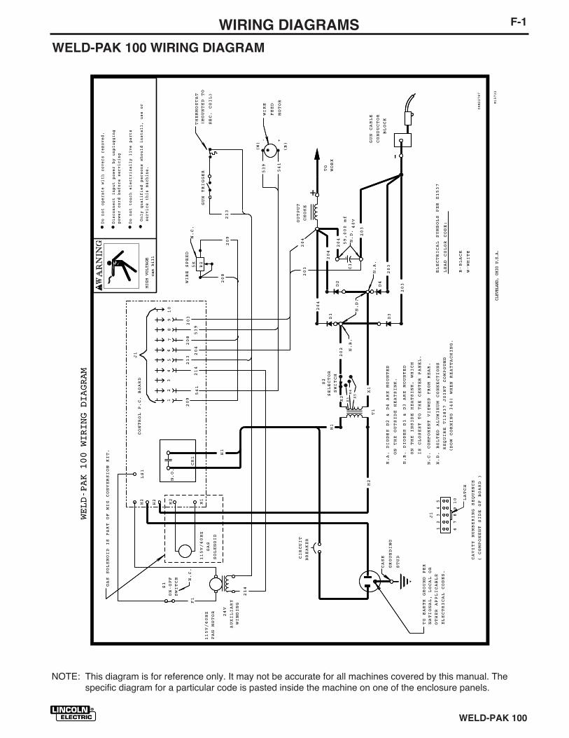
F-1WIRING DIAGRAMS
WELD-PAK 100
WELD-PAK 100 WIRING DIAGRAM
S1
SWITCH
D1
D3
D2
D4
204
204
204
203
203
203
C1
59,000
mf
40V
203
204
-
+
GUN
CABLE
CONDUCTOR
BLOCK
TO
WORK
ELECTRICAL
SYMBOLS
PER
E1537
CAVITY
NUMBERING
SEQUENCE
(COMPONENT
SIDE
OF
BOARD
)
539
541
T1
213
GUN
TRIGGER
THERMOSTAT
208
5K
WIRE
SPEED
R2
(W)
(B)
N.C.
N.C.
COMPONENT
VIEWED
FROM
REAR.
ON-OFF N.C.
209
WINDING
24V
AUXILIARY
FAN
MOTOR
X1
202
X2
S2
SELECTOR
SWITCH
CIRCUIT
BREAKER
115V/60HZ
115V/60HZ
OUTPUT
CHOKE
X3
X4
X5
+
H1
H1
H2
F1
541
204
203
209
208
539
213
214
12
34
LATCH
5
67
89
10
12
34
56
78
910
GAS
SOLENOID
CONTROL
P.C.
BOARD
J1
J1
CR1
H1
H2
LS1
H2
H2
N.O.
214
N.B.
N.D.
N.A.
N.D.
HIGH
VOLTAGE
can
kill
Only
qualified
persons
should
install,
use
or
service
this
machine.
Do
not
operate
with
covers
removed.
Do
not
touch
electrically
live
parts
Disconnect
input
power
by
unplugging
power
cord
before
servicing
TO
EARTH
GROUND
PER
NATIONAL,
LOCAL
OR
OTHER
APPLICABLE
ELECTRICAL
CODES.
CLEV
ELAN
D,OH
IOU.
S.A.
M15732
WELD-PAK
100
WIRING
DIAGRAM
GAS
SOLENOID
IS
PART
OF
MIG
CONVERSION
KIT.
- +
(MOUNTED
TO
SEC.
COIL)
WIRE
FEED
MOTOR
CASE
GROUNDING
STUD
N.A.
DIODES
D2
&D4
ARE
MOUNTED
ON
THE
OUTSIDE
HEATSINK.
N.B.
DIODES
D1
&D3
ARE
MOUNTED
ON
THE
INSIDE
HEATSINK,
WHICH
IS
CLOSEST
TO
THE
CENTER
PANEL.
N.D.
BOLTED
ALUMINUM
CONNECTIONS
LEAD
COLOR
CODE:
B-BLACK
W-WHITE
(DOW
CORNING
340)
WHEN
REATTACHING.
REQUIRE
T12837
JOINT
COMPOUND
CRM22787
NOTE: This diagram is for reference only. It may not be accurate for all machines covered by this manual. Thespecific diagram for a particular code is pasted inside the machine on one of the enclosure panels.

F-2 NOTES
WELD-PAK 100
NOTE: This Parts Manual is provided as an informative guide only, when ordering parts always refer to the LincolnElectric Parts List.
WELD-PAK 100
WELD-PAK 100PARTS MANUAL
PARTS
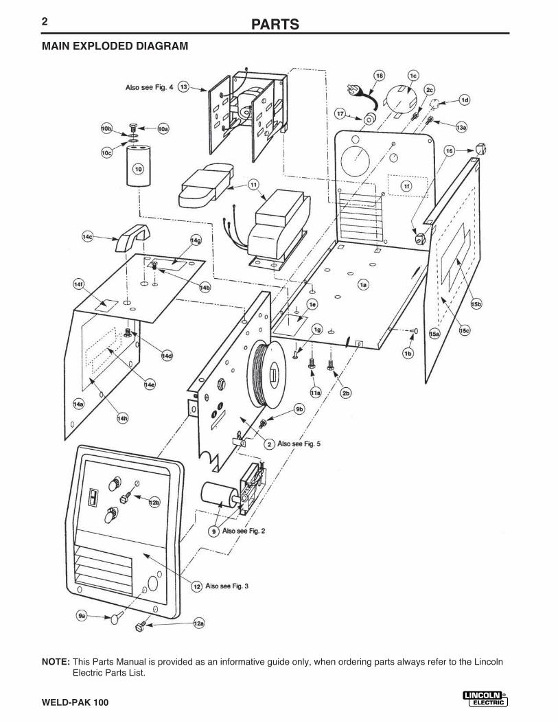
WELD-PAK 100
NOTE: This Parts Manual is provided as an informative guide only, when ordering parts always refer to the LincolnElectric Parts List.
2 PARTSMAIN EXPLODED DIAGRAM
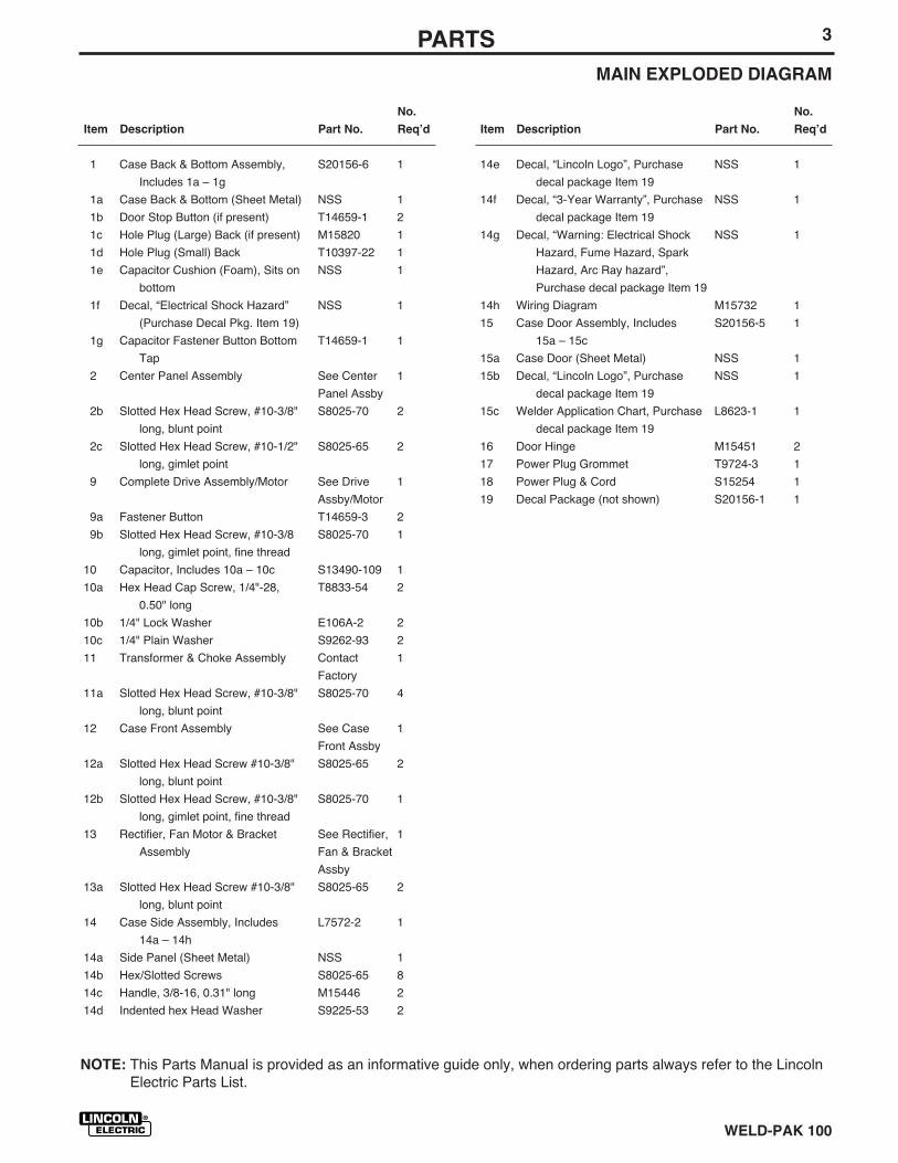
WELD-PAK 100
NOTE: This Parts Manual is provided as an informative guide only, when ordering parts always refer to the LincolnElectric Parts List.
3PARTSMAIN EXPLODED DIAGRAM
1 Case Back & Bottom Assembly, S20156-6 1
Includes 1a – 1g
1a Case Back & Bottom (Sheet Metal) NSS 1
1b Door Stop Button (if present) T14659-1 2
1c Hole Plug (Large) Back (if present) M15820 1
1d Hole Plug (Small) Back T10397-22 1
1e Capacitor Cushion (Foam), Sits on NSS 1
bottom
1f Decal, “Electrical Shock Hazard” NSS 1
(Purchase Decal Pkg. Item 19)
1g Capacitor Fastener Button Bottom T14659-1 1
Tap
2 Center Panel Assembly See Center 1
Panel Assby
2b Slotted Hex Head Screw, #10-3/8" S8025-70 2
long, blunt point
2c Slotted Hex Head Screw, #10-1/2" S8025-65 2
long, gimlet point
9 Complete Drive Assembly/Motor See Drive 1
Assby/Motor
9a Fastener Button T14659-3 2
9b Slotted Hex Head Screw, #10-3/8 S8025-70 1
long, gimlet point, fine thread
10 Capacitor, Includes 10a – 10c S13490-109 1
10a Hex Head Cap Screw, 1/4"-28, T8833-54 2
0.50" long
10b 1/4" Lock Washer E106A-2 2
10c 1/4" Plain Washer S9262-93 2
11 Transformer & Choke Assembly Contact 1
Factory
11a Slotted Hex Head Screw, #10-3/8" S8025-70 4
long, blunt point
12 Case Front Assembly See Case 1
Front Assby
12a Slotted Hex Head Screw #10-3/8" S8025-65 2
long, blunt point
12b Slotted Hex Head Screw, #10-3/8" S8025-70 1
long, gimlet point, fine thread
13 Rectifier, Fan Motor & Bracket See Rectifier, 1
Assembly Fan & Bracket
Assby
13a Slotted Hex Head Screw #10-3/8" S8025-65 2
long, blunt point
14 Case Side Assembly, Includes L7572-2 1
14a – 14h
14a Side Panel (Sheet Metal) NSS 1
14b Hex/Slotted Screws S8025-65 8
14c Handle, 3/8-16, 0.31" long M15446 2
14d Indented hex Head Washer S9225-53 2
14e Decal, “Lincoln Logo”, Purchase NSS 1
decal package Item 19
14f Decal, “3-Year Warranty”, Purchase NSS 1
decal package Item 19
14g Decal, “Warning: Electrical Shock NSS 1
Hazard, Fume Hazard, Spark
Hazard, Arc Ray hazard”,
Purchase decal package Item 19
14h Wiring Diagram M15732 1
15 Case Door Assembly, Includes S20156-5 1
15a – 15c
15a Case Door (Sheet Metal) NSS 1
15b Decal, “Lincoln Logo”, Purchase NSS 1
decal package Item 19
15c Welder Application Chart, Purchase L8623-1 1
decal package Item 19
16 Door Hinge M15451 2
17 Power Plug Grommet T9724-3 1
18 Power Plug & Cord S15254 1
19 Decal Package (not shown) S20156-1 1
No.
Item Description Part No. Reqʼd
No.
Item Description Part No. Reqʼd
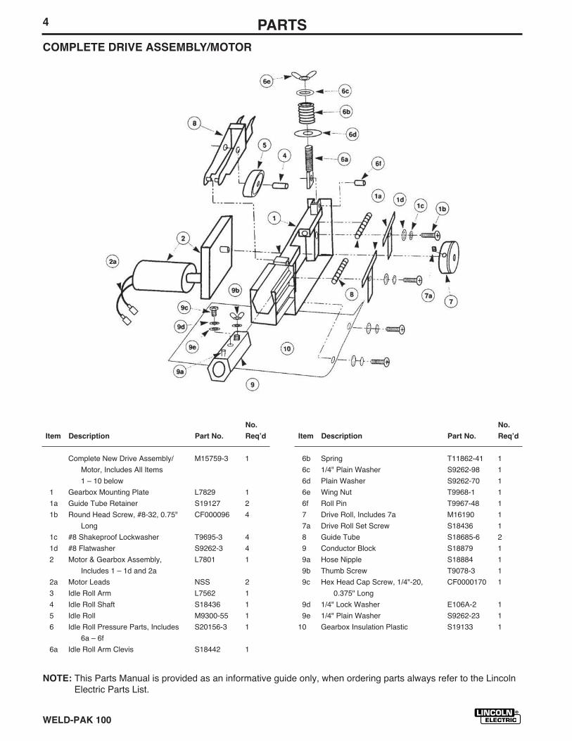
WELD-PAK 100
NOTE: This Parts Manual is provided as an informative guide only, when ordering parts always refer to the LincolnElectric Parts List.
4 PARTSCOMPLETE DRIVE ASSEMBLY/MOTOR
Complete New Drive Assembly/ M15759-3 1
Motor, Includes All Items
1 – 10 below
1 Gearbox Mounting Plate L7829 1
1a Guide Tube Retainer S19127 2
1b Round Head Screw, #8-32, 0.75" CF000096 4
Long
1c #8 Shakeproof Lockwasher T9695-3 4
1d #8 Flatwasher S9262-3 4
2 Motor & Gearbox Assembly, L7801 1
Includes 1 – 1d and 2a
2a Motor Leads NSS 2
3 Idle Roll Arm L7562 1
4 Idle Roll Shaft S18436 1
5 Idle Roll M9300-55 1
6 Idle Roll Pressure Parts, Includes S20156-3 1
6a – 6f
6a Idle Roll Arm Clevis S18442 1
No.
Item Description Part No. Reqʼd
6b Spring T11862-41 1
6c 1/4" Plain Washer S9262-98 1
6d Plain Washer S9262-70 1
6e Wing Nut T9968-1 1
6f Roll Pin T9967-48 1
7 Drive Roll, Includes 7a M16190 1
7a Drive Roll Set Screw S18436 1
8 Guide Tube S18685-6 2
9 Conductor Block S18879 1
9a Hose Nipple S18884 1
9b Thumb Screw T9078-3 1
9c Hex Head Cap Screw, 1/4"-20, CF0000170 1
0.375" Long
9d 1/4" Lock Washer E106A-2 1
9e 1/4" Plain Washer S9262-23 1
10 Gearbox Insulation Plastic S19133 1
No.
Item Description Part No. Reqʼd
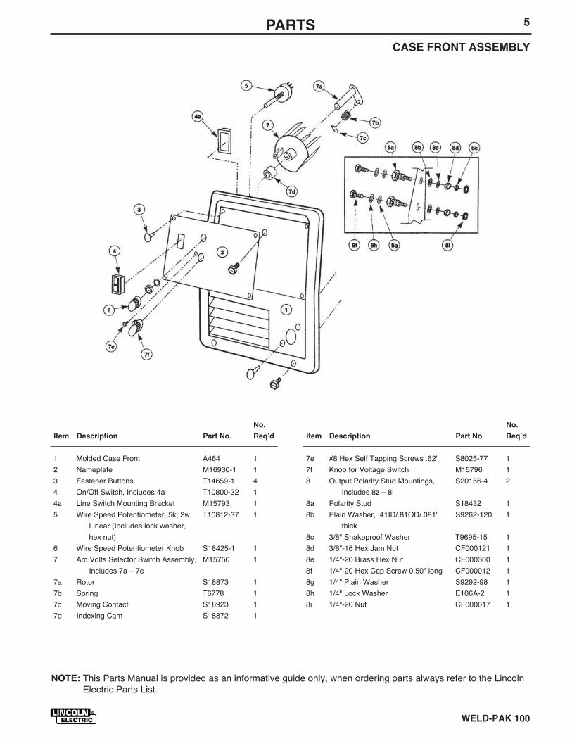
WELD-PAK 100
NOTE: This Parts Manual is provided as an informative guide only, when ordering parts always refer to the LincolnElectric Parts List.
5PARTSCASE FRONT ASSEMBLY
1 Molded Case Front A464 1
2 Nameplate M16930-1 1
3 Fastener Buttons T14659-1 4
4 On/Off Switch, Includes 4a T10800-32 1
4a Line Switch Mounting Bracket M15793 1
5 Wire Speed Potentiometer, 5k, 2w, T10812-37 1
Linear (Includes lock washer,
hex nut)
6 Wire Speed Potentiometer Knob S18425-1 1
7 Arc Volts Selector Switch Assembly, M15750 1
Includes 7a – 7e
7a Rotor S18873 1
7b Spring T6778 1
7c Moving Contact S18923 1
7d Indexing Cam S18872 1
No.
Item Description Part No. Reqʼd
7e #8 Hex Self Tapping Screws .62" S8025-77 1
7f Knob for Voltage Switch M15796 1
8 Output Polarity Stud Mountings, S20156-4 2
Includes 8z – 8i
8a Polarity Stud S18432 1
8b Plain Washer, .41ID/.81OD/.081" S9262-120 1
thick
8c 3/8" Shakeproof Washer T9695-15 1
8d 3/8"-16 Hex Jam Nut CF000121 1
8e 1/4"-20 Brass Hex Nut CF000300 1
8f 1/4"-20 Hex Cap Screw 0.50" long CF000012 1
8g 1/4" Plain Washer S9292-98 1
8h 1/4" Lock Washer E106A-2 1
8i 1/4"-20 Nut CF000017 1
No.
Item Description Part No. Reqʼd

WELD-PAK 100
NOTE: This Parts Manual is provided as an informative guide only, when ordering parts always refer to the LincolnElectric Parts List.
6 PARTSRECTIFIER, FAN AND BRACKET ASSEMBLY
Complete Assembly, Includes L7680-2 1
Items 1 – 5 below
1 Bracket for Fan & Rectifier G1839 1
2 Rectifier Assembly (both sides M15447-1 1
with leads)
2a Rectifier Plate M15444 2
2b Rectifier Diode, 70A, 300V, Anode M9661-40R 2
Stud
2c Rectifier Diode, 70A, 300V, M9661-40 2
Cathode Stud
3 Fan Motor M15787-1 1
4 Fan Blade M15432 1
5 Sems Screw to mount motor T10082-27 2
No.
Item Description Part No. Reqʼd
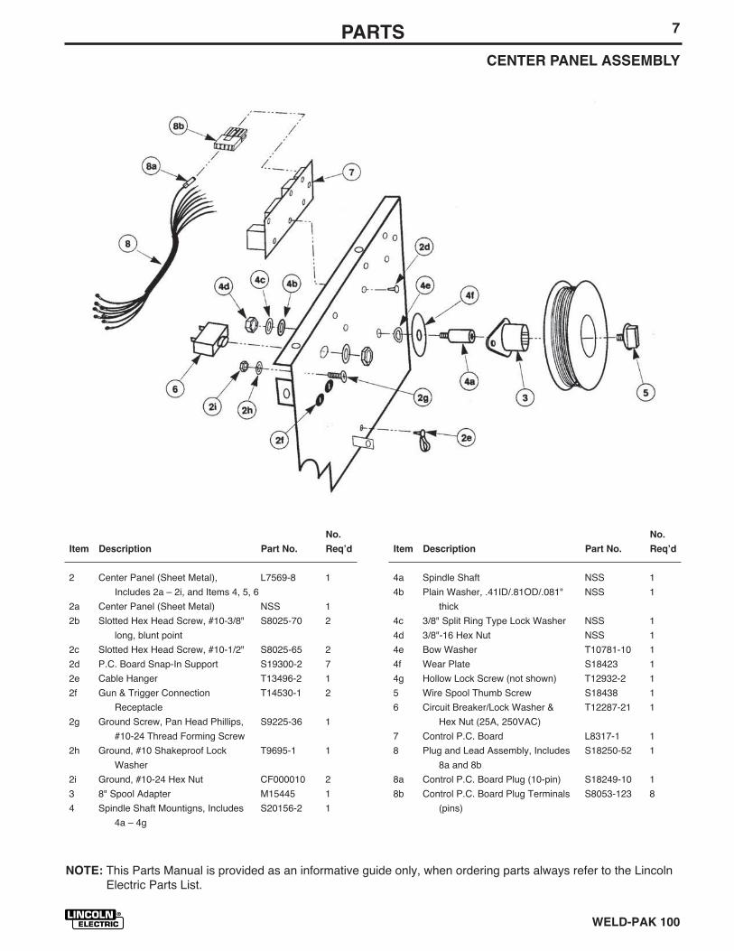
WELD-PAK 100
NOTE: This Parts Manual is provided as an informative guide only, when ordering parts always refer to the LincolnElectric Parts List.
7PARTSCENTER PANEL ASSEMBLY
2 Center Panel (Sheet Metal), L7569-8 1
Includes 2a – 2i, and Items 4, 5, 6
2a Center Panel (Sheet Metal) NSS 1
2b Slotted Hex Head Screw, #10-3/8" S8025-70 2
long, blunt point
2c Slotted Hex Head Screw, #10-1/2" S8025-65 2
2d P.C. Board Snap-In Support S19300-2 7
2e Cable Hanger T13496-2 1
2f Gun & Trigger Connection T14530-1 2
Receptacle
2g Ground Screw, Pan Head Phillips, S9225-36 1
#10-24 Thread Forming Screw
2h Ground, #10 Shakeproof Lock T9695-1 1
Washer
2i Ground, #10-24 Hex Nut CF000010 2
3 8" Spool Adapter M15445 1
4 Spindle Shaft Mountigns, Includes S20156-2 1
4a – 4g
No.
Item Description Part No. Reqʼd
4a Spindle Shaft NSS 1
4b Plain Washer, .41ID/.81OD/.081" NSS 1
thick
4c 3/8" Split Ring Type Lock Washer NSS 1
4d 3/8"-16 Hex Nut NSS 1
4e Bow Washer T10781-10 1
4f Wear Plate S18423 1
4g Hollow Lock Screw (not shown) T12932-2 1
5 Wire Spool Thumb Screw S18438 1
6 Circuit Breaker/Lock Washer & T12287-21 1
Hex Nut (25A, 250VAC)
7 Control P.C. Board L8317-1 1
8 Plug and Lead Assembly, Includes S18250-52 1
8a and 8b
8a Control P.C. Board Plug (10-pin) S18249-10 1
8b Control P.C. Board Plug Terminals S8053-123 8
(pins)
No.
Item Description Part No. Reqʼd
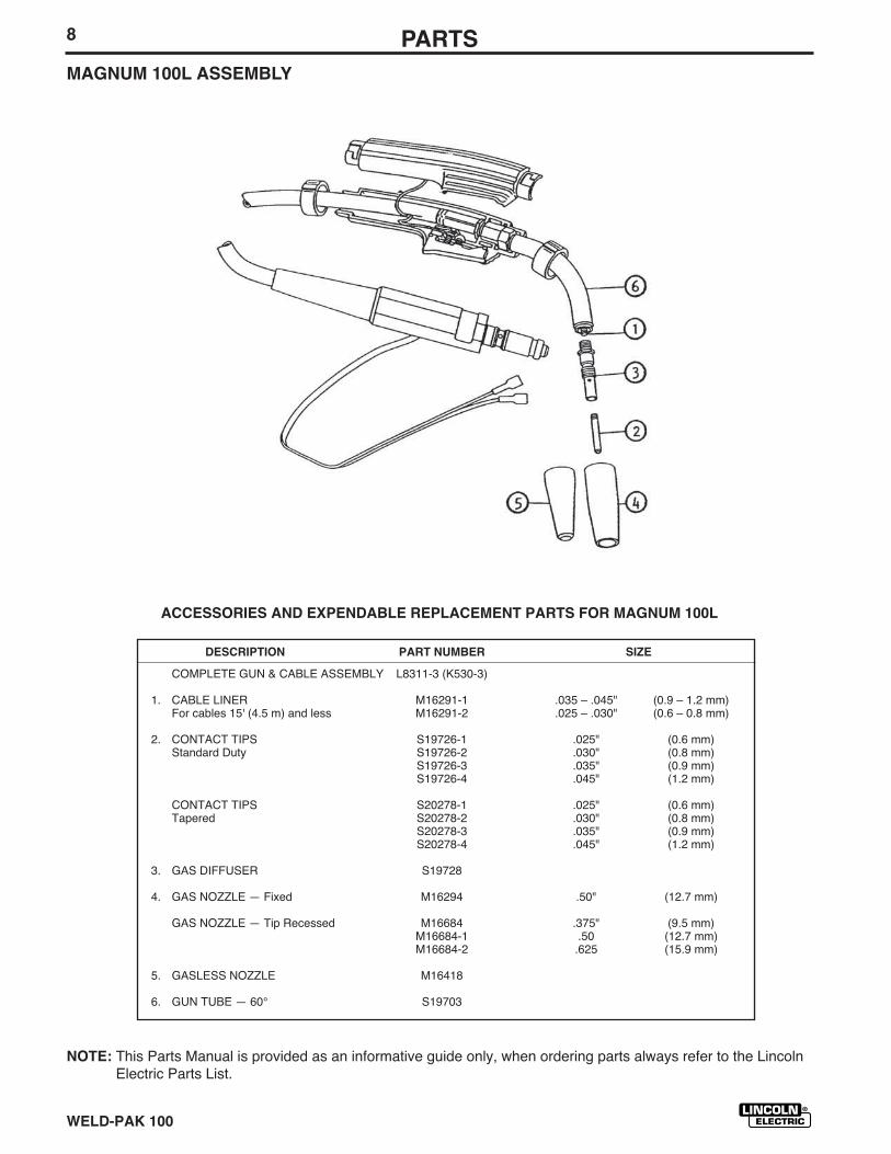
WELD-PAK 100
NOTE: This Parts Manual is provided as an informative guide only, when ordering parts always refer to the LincolnElectric Parts List.
8 PARTSMAGNUM 100L ASSEMBLY
ACCESSORIES AND EXPENDABLE REPLACEMENT PARTS FOR MAGNUM 100L
DESCRIPTION PART NUMBER SIZE
COMPLETE GUN & CABLE ASSEMBLY L8311-3 (K530-3)
1. CABLE LINER M16291-1 .035 – .045" (0.9 – 1.2 mm)For cables 15' (4.5 m) and less M16291-2 .025 – .030" (0.6 – 0.8 mm)
2. CONTACT TIPS S19726-1 .025" (0.6 mm)Standard Duty S19726-2 .030" (0.8 mm)
S19726-3 .035" (0.9 mm)S19726-4 .045" (1.2 mm)
CONTACT TIPS S20278-1 .025" (0.6 mm)Tapered S20278-2 .030" (0.8 mm)
S20278-3 .035" (0.9 mm)S20278-4 .045" (1.2 mm)
3. GAS DIFFUSER S19728
4. GAS NOZZLE — Fixed M16294 .50" (12.7 mm)
GAS NOZZLE — Tip Recessed M16684 .375" (9.5 mm)M16684-1 .50 (12.7 mm)M16684-2 .625 (15.9 mm)
5. GASLESS NOZZLE M16418
6. GUN TUBE — 60° S19703

NOTES
SQUARE WAVE TIG 255

NOTES
SQUARE WAVE TIG 255
Now Available...12th EditionThe Procedure Handbook of Arc Welding
With over 500,000 copies of previous editions publishedsince 1933, the Procedure Handbook is considered by many tobe the “Bible” of the arc welding industry.
This printing wil l go fast so donʼt delay. Place yourorder now using the coupon below.
The hardbound book contains over 750 pages of weldinginformation, techniques and procedures. Much of this materialhas never been included in any other book.
A must for all welders, supervisors, engineers anddesigners. Many welding instructors will want to use the bookas a reference for all students by taking advantage of the lowquantity discount prices which include shipping by4th class parcel post.
$15.00 postage paid U.S.A. Mainland
How To Read Shop Drawings
The book contains the latest information and applicationdata on the American Welding Society Standard WeldingSymbols. Detailed discussion tells how engineers anddraftsmen use the “short-cut” language of symbols to passon assembly and welding information to shop personnel.
Practical exercises and examples develop the readerʼs abilityto visualize mechanically drawn objects as they will appearin their assembled form.
187 pages with more than 100 illustrations. Size 8-1/2” x 11”Durable, cloth-covered board binding.
$4.50 postage paid U.S.A. Mainland
New Lessons in Arc WeldingLessons, simply written, cover manipulatory techniques;
machine and electrode characteristics; related subjects,such as distortion; and supplemental information on arcwelding applications, speeds and costs. Practice materials,exercises, questions and answers are suggested for eachlesson.
528 pages, well illustrated, 6” x 9” size, bound in simulated,gold embossed leather.
$5.00 postage paid U.S.A. Mainland
Need Welding Training?The Lincoln Electric Company operates the oldest and
most respected Arc Welding School in the United States at itscorporate headquarters in Cleveland, Ohio. Over 100,000 stu-dents have graduated. Tuit ion is low and the training is“hands on”
For details write: Lincoln Welding School22801 St. Clair Ave.Cleveland, Ohio 44117-1199.
and ask for bulletin ED-80 or call 216-383-2259 and ask for theWelding School Registrar.
Lincoln Welding SchoolBASIC COURSE $700.00
5 weeks of fundamentalsThere is a 10% discount on all orders of $50.00 or more for shipment at one time to one location.Orders of $50 or less before discount or orders outside of North America must be prepaid with charge, check or money order in U.S. Funds Only.Prices include shipment by 4 thClass Book Rate for U.S.A. Mainland Only. Please allow up to 4 weeks for delivery.UPS Shipping for North America Only. All prepaid orders that request UPS shipment please add:
$5.00 For order value up to $49.99$10.00 For order value between $50.00 & $99.99$15.00 For order value between $100.00 & $149.00
For North America invoiced orders over $50.00 & credit card orders, if UPS is requested, it will be invoiced or charged to you at cost.Outside U.S.A. Mainland order must be prepaid in U.S. Funds. Please add $2.00 per book for surface mail or $15.00 per book for air parcel post shipment.METHOD OF PAYMENT: (Sorry, No C.O.D. Orders)
CHECK ONE:Name: _______________________________________________
Please Invoice (only if order is over $50.00)Address: _______________________________________________
Check or Money Order Enclosed, U.S. Funds only _______________________________________________
Credit Card - Telephone: _______________________________________________
Signature as it appears on Charge Card:Account No. |_|_|_|_|_|_|_|_|_|_|_|_|_|_|_|_|_|_|_|_|_| Exp Date |_|_| |_|_| ______________________Month Year
USE THIS FORM TO ORDER: Order from: BOOK DIVISION, The Lincoln Electric Company, 22801 St. Clair Avenue, Cleveland, Ohio 44117-1199BOOKS OR FREE INFORMATIVE CATALOGS Telephone: 216-383-2211 or, for fastest service, FAX this completed form to: 216-361-5901.
Lincoln Welding School Titles: Price Code Quantity Cost(ED-80) New Lessons in Arc Welding $5.00 L
Seminar Information Procedure Handbook “Twelfth Edition” $15.00 PH(ED-45) How to Read Shop Drawings $4.50 H
Educational Video Information Incentive Management $5.00 IM(ED-93) A New Approach to Industrial Economics $5.00 NA
James F. Lincoln Arc Welding The American Century of John C. Lincoln $5.00 ACFoundation Book Information Welding Preheat Calculator $3.00 WC-8
(JFLF-515) Pipe Welding Charts $4.50 ED-89SUB TOTAL
Additional Shipping Costs if anyTOTAL COST
VISA ® MasterCardMasterCard®
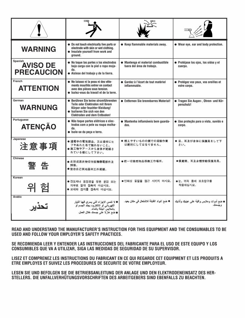
WARNING
AVISO DEPRECAUCION
ATTENTION
WARNUNG
ATENÇÃO
Spanish
French
German
Portuguese
Japanese
Chinese
Korean
Arabic
READ AND UNDERSTAND THE MANUFACTURER’S INSTRUCTION FOR THIS EQUIPMENT AND THE CONSUMABLES TO BEUSED AND FOLLOW YOUR EMPLOYER’S SAFETY PRACTICES.
SE RECOMIENDA LEER Y ENTENDER LAS INSTRUCCIONES DEL FABRICANTE PARA EL USO DE ESTE EQUIPO Y LOSCONSUMIBLES QUE VA A UTILIZAR, SIGA LAS MEDIDAS DE SEGURIDAD DE SU SUPERVISOR.
LISEZ ET COMPRENEZ LES INSTRUCTIONS DU FABRICANT EN CE QUI REGARDE CET EQUIPMENT ET LES PRODUITS AETRE EMPLOYES ET SUIVEZ LES PROCEDURES DE SECURITE DE VOTRE EMPLOYEUR.
LESEN SIE UND BEFOLGEN SIE DIE BETRIEBSANLEITUNG DER ANLAGE UND DEN ELEKTRODENEINSATZ DES HER-STELLERS. DIE UNFALLVERHÜTUNGSVORSCHRIFTEN DES ARBEITGEBERS SIND EBENFALLS ZU BEACHTEN.
● Do not touch electrically live parts orelectrode with skin or wet clothing.
● Insulate yourself from work andground.
● No toque las partes o los electrodosbajo carga con la piel o ropa moja-da.
● Aislese del trabajo y de la tierra.
● Ne laissez ni la peau ni des vête-ments mouillés entrer en contactavec des pièces sous tension.
● Isolez-vous du travail et de la terre.
● Berühren Sie keine stromführendenTeile oder Elektroden mit IhremKörper oder feuchter Kleidung!
● Isolieren Sie sich von denElektroden und dem Erdboden!
● Não toque partes elétricas e elec-trodos com a pele ou roupa molha-da.
● Isole-se da peça e terra.
● Keep flammable materials away.
● Mantenga el material combustiblefuera del área de trabajo.
● Gardez à l’écart de tout matérielinflammable.
● Entfernen Sie brennbarres Material!
● Mantenha inflamáveis bem guarda-dos.
● Wear eye, ear and body protection.
● Protéjase los ojos, los oídos y elcuerpo.
● Protégez vos yeux, vos oreilles etvotre corps.
● Tragen Sie Augen-, Ohren- und Kör-perschutz!
● Use proteção para a vista, ouvido ecorpo.
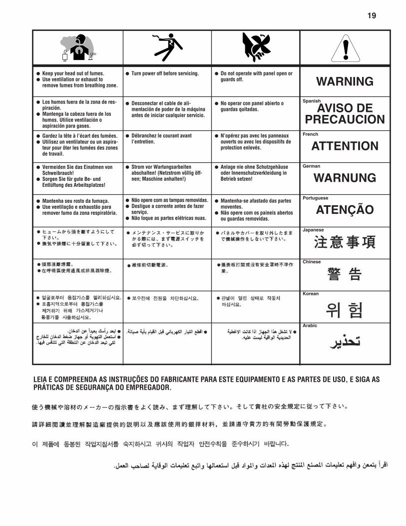
19
WARNING
AVISO DEPRECAUCION
ATTENTION
WARNUNG
ATENÇÃO
Spanish
French
German
Portuguese
Japanese
Chinese
Korean
Arabic
LEIA E COMPREENDA AS INSTRUÇÕES DO FABRICANTE PARA ESTE EQUIPAMENTO E AS PARTES DE USO, E SIGA ASPRÁTICAS DE SEGURANÇA DO EMPREGADOR.
● Keep your head out of fumes.● Use ventilation or exhaust to
remove fumes from breathing zone.
● Los humos fuera de la zona de res-piración.
● Mantenga la cabeza fuera de loshumos. Utilice ventilación oaspiración para gases.
● Gardez la tête à l’écart des fumées.● Utilisez un ventilateur ou un aspira-
teur pour ôter les fumées des zonesde travail.
● Vermeiden Sie das Einatmen vonSchweibrauch!
● Sorgen Sie für gute Be- undEntlüftung des Arbeitsplatzes!
● Mantenha seu rosto da fumaça.● Use ventilação e exhaustão para
remover fumo da zona respiratória.
● Turn power off before servicing.
● Desconectar el cable de ali-mentación de poder de la máquinaantes de iniciar cualquier servicio.
● Débranchez le courant avantl’entretien.
● Strom vor Wartungsarbeitenabschalten! (Netzstrom völlig öff-nen; Maschine anhalten!)
● Não opere com as tampas removidas.● Desligue a corrente antes de fazer
serviço.● Não toque as partes elétricas nuas.
● Do not operate with panel open orguards off.
● No operar con panel abierto oguardas quitadas.
● N’opérez pas avec les panneauxouverts ou avec les dispositifs deprotection enlevés.
● Anlage nie ohne Schutzgehäuseoder Innenschutzverkleidung inBetrieb setzen!
● Mantenha-se afastado das partesmoventes.
● Não opere com os paineis abertosou guardas removidas.
STATEMENT OF LIMITED WARRANTYThe Lincoln Electric Company (Lincoln) warrants to theend user (purchaser) of all new welding and cutting equip-ment, electrode and flux (collectively called the “Goods”)that it will be free of defects in workmanship and material.
This warranty is void if Lincoln or its Authorized ServiceFacility finds that the equipment has been subjected toimproper installation, improper care or abnormal opera-tions.
WARRANTY PERIOD (1) (2) (3)
Lincoln will assume both the parts and labor expense ofcorrecting defects during the full warranty period. All war-ranty periods date from the date of purchase to the originalend user or from the date of manufacture if the originalinvoice cannot be provided and are as follows:
7 Years• Main power rectifiers on all non-inverter low frequency
(50 and 60 Hz) type welders.
3 Years• All Lincoln welding machines, wirefeeders and plasma
cutting machines unless listed below.
2 Years• Power Arc 4000, Power Arc 5000
Pro-Cut 25, Weldanpower 125
1 Year• AC-100
Invertec V100-S, Invertec V130-S, Invertec V200-THandy MIG 101, Handy Core 100
• All water coolers (internal or external models)
• All stick electrode, welding wire and flux.
• Arc welding and cutting robots and robotic controllers
• All Environmental Systems equipment, including portableunits, central units and accessories. (Does not includeconsumable items listed under 30 day warranty.)
• All welding and cutting accessories including wire feedmodules, undercarriages, field installed options that aresold separately, unattached options, welding supplies,standard accessory sets, replacement parts, andMagnum products. (Does not include expendable partsand guns/torches listed under 90 and 30 day warranties)
90 Days• All gun and cable assemblies, TIG and plasma torches
and spool guns.
30 Days• All consumable items that may be used with the environ-
mental systems described above. This includes hoses,filters, belts and hose adapters.
• Expendable Parts - Lincoln is not responsible for thereplacement of any expendable part that is required dueto normal wear.
CONDITIONS OF WARRANTYTO OBTAIN WARRANTY COVERAGE:The purchaser must contact Lincoln or Lincolnʼs AuthorizedService Facility about any defect claimed under Lincolnʼswarranty.
Determination of warranty on welding and cutting equip-ment will be made by Lincoln or Lincolnʼs AuthorizedService Facility.
WARRANTY REPAIR:If Lincoln or Lincolnʼs Authorized Service Facility confirmsthe existence of a defect covered by this warranty, thedefect will be corrected by repair or replacement atLincolnʼs option.
At Lincolnʼs request, the purchaser must return, to Lincolnor its Authorized Service Facility, any “Goods” claimeddefective under Lincolnʼs warranty.
FREIGHT COSTS:The purchaser is responsible for shipment to and from theLincoln Authorized Service Facility.
WARRANTY LIMITATIONSLincoln will not accept responsibility or liability for repairsmade outside of a Lincoln Authorized Service Facility.
Lincolnʼs liability under this warranty shall not exceed thecost of correcting the defect of the Lincoln product.
Lincoln will not be liable for incidental or consequentialdamages (such as loss of business, etc.) caused by thedefect or the time involved to correct the defect.
This written warranty is the only express warranty providedby Lincoln with respect to its products. Warranties impliedby law such as the warranty of merchantability are limitedto the duration of this limited warranty for the equipmentinvolved.
This warranty gives the purchaser specific legal rights. Thepurchaser may also have other rights which vary from stateto state.
(1) Equipment manufactured for the Lincoln Electric Company is subject to
the warranty period of the original manufacturer.
(2) All engines and engine accessories are warranted by the engine orengine accessory manufacturer and are not covered by this warranty.
(3) SAE400 WELD Nʼ AIR compressor is warranted by the compressor man-
ufacturer and not covered by this warranty.
LIMITED WARRANTY
May, ʻ99
• Sales and Service through Subsidiaries and Distributors Worldwide •
Cleveland, Ohio 44117-1199 U.S.A. TEL: 216.481.8100 FAX: 216.486.1751 WEB SITE: www.lincolnelectric.com
• World's Leader in Welding and Cutting Products •
warranty superseded
see imws 1