Embed Size (px)
Citation preview
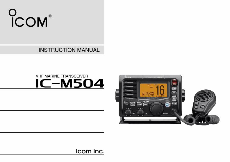
INSTRUCTION MANUAL
iM504VHF MARINE TRANSCEIVER
i
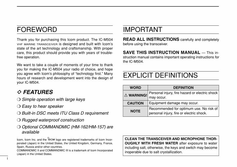
FOREWORDThank you for purchasing this Icom product. The IC-M504VHF MARINE TRANSCEIVER is designed and built with Icom’sstate of the art technology and craftsmanship. With propercare, this product should provide you with years of trouble-free operation.
We want to take a couple of moments of your time to thankyou for making the IC-M504 your radio of choice, and hopeyou agree with Icom’s philosophy of “technology first.” Manyhours of research and development went into the design ofyour IC-M504.
D FEATURES Simple operation with large keys
Easy to hear speaker
Built-in DSC meets ITU Class D requirement
Rugged waterproof construction
Optional COMMANDMIC (HM-162/HM-157) areavailable
IMPORTANTREAD ALL INSTRUCTIONS carefully and completelybefore using the transceiver.
SAVE THIS INSTRUCTION MANUAL — This in-struction manual contains important operating instructions forthe IC-M504.
EXPLICIT DEFINITIONS
WORD DEFINITION
R WARNING!
CAUTION
NOTE
Personal injury, fire hazard or electric shockmay occur.
Equipment damage may occur.
Recommended for optimum use. No risk ofpersonal injury, fire or electric shock.
CLEAN THE TRANSCEIVER AND MICROPHONE THOR-OUGHLY WITH FRESH WATER after exposure to waterincluding salt, otherwise, the keys and switch may becomeinoperable due to salt crystallization.
Icom, Icom Inc. and the logo are registered trademarks of Icom Incor-porated (Japan) in the United States, the United Kingdom, Germany, France,Spain, Russia and/or other countries. COMMANDMIC II and COMMANDMIC III is a trademark of Icom Incorporated(Japan) in the United States.
ii
IN CASE OF EMERGENCYIf your vessel requires assistance, contact other vessels andthe Coast Guard by sending a Distress call on Channel 16.
Or, transmit your Distress call using digital selective callingon Channel 70.
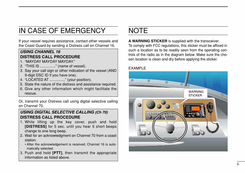
NOTEA WARNING STICKER is supplied with the transceiver.To comply with FCC regulations, this sticker must be affixed insuch a location as to be readily seen from the operating con-trols of the radio as in the diagram below. Make sure the cho-sen location is clean and dry before applying the sticker.
EXAMPLE
WARNING STICKER
USING DIGITAL SELECTIVE CALLING (Ch 70)DISTRESS CALL PROCEDURE1. While lifting up the key cover, push and hold
[DISTRESS] for 5 sec. until you hear 5 short beepschange to one long beep.
2. Wait for an acknowledgment on Channel 70 from a coaststation.• After the acknowledgement is received, Channel 16 is auto-
matically selected.3. Push and hold [PTT], then transmit the appropriate
information as listed above.
USING CHANNEL 16DISTRESS CALL PROCEDURE1. “MAYDAY MAYDAY MAYDAY.”2. “THIS IS ...............” (name of vessel).3. Say your call sign or other indication of the vessel (AND
9-digit DSC ID if you have one).4. “LOCATED AT ...............” (your position).5. State the nature of the distress and assistance required.6. Give any other information which might facilitate the
rescue.
iii
RADIO OPERATOR WARNINGIcom requires the radio operator to meet theFCC Requirements for Radio Frequency Expo-sure. An omnidirectional antenna with gain notgreater than 9 dBi must be mounted a minimumof 5 meters (measured from the lowest point ofthe antenna) vertically above the main deck and
all possible personnel. This is the minimum safe separationdistance estimated to meet all RF exposure compliance re-quirements. This 5 meter distance is based on the FCC SafeMaximum Permissible Exposure (MPE) distance of 3 metersadded to the height of an adult (2 meters) and is appropriatefor all vessels.
For watercraft without suitable structures, the antenna mustbe mounted so as to maintain a minimum of 1 meter verticallybetween the antenna, (measured from the lowest point of theantenna), to the heads of all persons AND all persons muststay outside of the 3 meter MPE radius.
Do not transmit with radio and antenna when persons arewithin the MPE radius of the antenna, unless such persons(such as driver or radio operator) are shielded from antennafield by a grounded metallic barrier. The MPE Radius is theminimum distance from the antenna axis that person shouldmaintain in order to avoid RF exposure higher than the allow-able MPE level set by FCC.
W ARNING
FAILURE TO OBSERVE THESE LIMITS MAY ALLOWTHOSE WITHIN THE MPE RADIUS TO EXPERIENCE RFRADIATION ABSORPTION WHICH EXCEEDS THE FCCMAXIMUM PERMISSIBLE EXPOSURE (MPE) LIMIT.IT IS THE RESPONSIBILITY OF THE RADIO OPERATORTO ENSURE THAT THE MAXIMUM PERMISSIBLE EXPO-SURE LIMITS ARE OBSERVED AT ALL TIMES DURINGRADIO TRANSMISSION. THE RADIO OPERATOR IS TOENSURE THAT NO BYSTANDERS COME WITHIN THERADIUS OF THE MAXIMUM PERMISSIBLE EXPOSURELIMITS.
Determining MPE RadiusTHE MAXIMUM PERMISSIBLE EXPOSURE (MPE) RA-DIUS HAS BEEN ESTIMATED TO BE A RADIUS OFABOUT 3M PER OET BULLETIN 65 OF THE FCC.THIS ESTIMATE IS MADE ASSUMING THE MAXIMUMPOWER OF THE RADIO AND ANTENNAS WITH A MAXI-MUM GAIN OF 9dBi ARE USED FOR A SHIP MOUNTEDSYSTEM.
iv
FOREWORD …………………………………………………………… iIMPORTANT …………………………………………………………… iEXPLICIT DEFINITIONS ……………………………………………… iIN CASE OF EMERGENCY…………………………………………… iiNOTE …………………………………………………………………… iiRADIO OPERATOR WARNING ……………………………………… iiiTABLE OF CONTENTS ……………………………………………… ivPRECAUTIONS ………………………………………………………… v1 OPERATING RULES ……………………………………………… 12 PANEL DESCRIPTION ………………………………………… 2–5
Front panel ……………………………………………………… 2 Function display ………………………………………………… 4 Microphone ……………………………………………………… 5
3 BASIC OPERATION…………………………………………… 6–11 Channel selection ……………………………………………… 6 Receiving and transmitting……………………………………… 8 Call channel programming ……………………………………… 9 Channel comments …………………………………………… 10 Microphone Lock function …………………………………… 10 Display backlight ……………………………………………… 10 Optional voice scrambler operation ………………………… 11
4 SCAN OPERATION ………………………………………… 12–13 Scan types ……………………………………………………… 12 Setting TAG channels ………………………………………… 13 Starting a scan ………………………………………………… 13
5 DUALWATCH/TRI-WATCH ……………………………………… 14 Description ……………………………………………………… 14 Operation ……………………………………………………… 14
6 DSC OPERATION …………………………………………… 15–49 MMSI code programming……………………………………… 15 MMSI code check ……………………………………………… 16 DSC address ID………………………………………………… 17
Position and time programming ……………………………… 21 Position and time indication …………………………………… 22 GPS information indication …………………………………… 22 Distress call …………………………………………………… 23 Transmitting DSC calls ………………………………………… 26 Receiving DSC calls …………………………………………… 41 Received messages …………………………………………… 45 DSC Set mode ………………………………………………… 47
7 OTHER FUNCTIONS………………………………………… 50–54 Intercom operation …………………………………………… 50 RX Speaker function …………………………………………… 51 Hailer operation ………………………………………………… 52 Automatic foghorn function …………………………………… 53
8 SET MODE …………………………………………………… 55–57 Set mode programming ……………………………………… 55 Set mode items ………………………………………………… 55
9 CONNECTIONS AND MAINTENANCE …………………… 58–64 Connections …………………………………………………… 58 Supplied accessories ………………………………………… 59 Antenna ………………………………………………………… 59 Fuse replacement ……………………………………………… 59 Mounting the transceiver ……………………………………… 60 MB-75 installation ……………………………………………… 61 UT-112/UT-98 installation……………………………………… 62 HM-162/HM-157 installation ………………………………… 63
10 TROUBLESHOOTING …………………………………………… 6711 SPECIFICATIONS AND OPTIONS …………………………… 68
Specifications …………………………………………………… 68 Options ………………………………………………………… 69
12 CHANNEL LIST ………………………………………………… 70TEMPLATE
TABLE OF CONTENTS 123456789101112
v
PRECAUTIONSRWARNING! NEVER connect the transceiver to an ACoutlet. This may pose a fire hazard or result in an electricshock.
CAUTION: Changes or modifications to this device, not ex-pressly approved by Icom Inc., could void your authority tooperate this device under FCC regulations.
NEVER connect the transceiver to a power source of morethan 16 V DC or use reverse polarity. This will ruin the trans-ceiver.
NEVER cut the DC power cable between the DC plug at theback of the transceiver and fuse holder. If an incorrect con-nection is made after cutting, the transceiver may be dam-aged.
NEVER place the transceiver where normal operation of thevessel may be hindered or where it could cause bodily injury.
KEEP the transceiver at least 3.3 ft (1 m) away from theship’s navigation compass.
DO NOT use or place the transceiver in areas with temper-atures below –4°F (–20°C) or above +140°F (+60°C) or, inareas subject to direct sunlight, such as the dashboard.
AVOID the use of chemical agents such as benzine or al-cohol when cleaning, as they may damage the transceiversurfaces. If the transceiver becomes dusty or dirty, wipe itclean with a soft, dry cloth.
BE CAREFUL! The transceiver rear panel will becomehot when operating continuously for long periods.Place the transceiver in a secure place to avoid inadvertentuse by children.
BE CAREFUL! The transceiver and the optional HM-162COMMANDMIC III™/HM-157 COMMANDMIC II™ employ water-proof construction, which corresponds to IPX8 of the interna-tional standard IEC 60529 (2001). However, once the trans-ceiver or microphone has been dropped, waterproofingcannot be guaranteed due to the fact that the case may becracked, or the waterproof seal damaged, etc.
1
1OPERATING RULES
DD PRIORITIES• Read all rules and regulations pertaining to priorities and
keep an up-to-date copy handy. Safety and Distress callstake priority over all others.
• You must monitor Channel 16 when you are not operatingon another channel.
• False or fraudulent distress signals are prohibited and pun-ishable by law.
DD PRIVACY• Information overheard but not intended for you cannot law-
fully be used in any way.
• Indecent or profane language is prohibited.
DD RADIO LICENSES(1) SHIP STATION LICENSEYou must have a current radio station license before using thetransceiver. It is unlawful to operate a ship station which is notlicensed.
Inquire through your dealer or the appropriate governmentagency for a Ship-Radiotelephone license application. Thisgovernment-issued license states the call sign which is yourcraft’s identification for radio purposes.
(2) OPERATOR’S LICENSEA Restricted Radiotelephone Operator Permit is the licensemost often held by small vessel radio operators when a radiois not required for safety purposes.
The Restricted Radiotelephone Operator Permit must beposted or kept with the operator. Only a licensed radio opera-tor may operate a transceiver.
However, non-licensed individuals may talk over a transceiverif a licensed operator starts, supervises, ends the call andmakes the necessary log entries.
Keep a copy of the current government rules and regulationshandy.
Radio license for boaters (U.S.A. only)The Telecommunications Act of 1996 permits recreationalboaters to have and use a VHF marine radio, EPIRB, andmarine radar without having an FCC ship station license.Boaters traveling on international voyages, having an HFsingle sideband radiotelephone or marine satellite termi-nal, or required to carry a marine radio under any otherregulation must still carry an FCC ship station license. Forfurther information, see the FCC Ship Radio Stations FactSheet.
1
2
PANEL DESCRIPTION2 Front panel
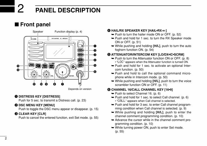
q DISTRESS KEY [DISTRESS]Push for 5 sec. to transmit a Distress call. (p. 23)
w DSC MENU KEY [MENU]Push to toggle the DSC menu appear or disappear. (p. 15)
e CLEAR KEY [CLR]Push to cancel the entered function, exit Set mode. (p. 55)
r HAIL/RX SPEAKER KEY [HAIL•RX ] Push to turn the hailer mode ON or OFF. (p. 52) Push and hold for 1 sec. to turn the RX Speaker mode
ON or OFF. (p. 51) While pushing and holding [H/L], push to turn the auto
foghorn function ON. (p. 54)
t ATTENUATOR/INTERCOM KEY [LO/DX•IC•SCRM] Push to turn the Attenuator function ON or OFF. (p. 8)
• “LLOOCC” appears when the Attenuator function is turned ON. Push and hold for 1 sec. to activate an optional Inter-
com function. (p. 50) Push and hold to call the optional command micro-
phone while in Intercom mode. (p. 50) While pushing and holding [H/L], push to turn the voice
scrambler function ON or OFF. (p. 11)
y CHANNEL 16/CALL CHANNEL KEY [16•9] Push to select Channel 16. (p. 6) Push and hold for 1 sec. to select Call channel. (p. 6)
• “CCAALLLL” appears when Call channel is selected. Push and hold for 3 sec. to enter Call channel program-
ming condition when Call channel is selected. (p. 9) While pushing and holding [H/L], push to enter the
channel comment programming condition. (p. 10) Advance the cursor while in the channel comment pro-
gramming condition. (p. 10) While turning power ON, push to enter Set mode.
(p. 55)
Function display (p. 4)Speaker
q
e
r
t
y
w
uio!0!1
!2
!3
Depends on version
3
2PANEL DESCRIPTION
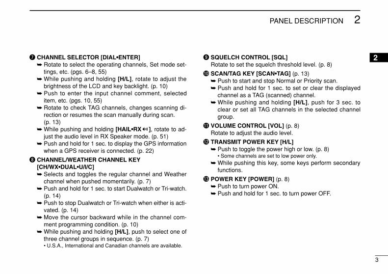
u CHANNEL SELECTOR [DIAL•ENTER] Rotate to select the operating channels, Set mode set-
tings, etc. (pgs. 6–8, 55) While pushing and holding [H/L], rotate to adjust the
brightness of the LCD and key backlight. (p. 10) Push to enter the input channel comment, selected
item, etc. (pgs. 10, 55) Rotate to check TAG channels, changes scanning di-
rection or resumes the scan manually during scan.(p. 13)
While pushing and holding [HAIL•RX ], rotate to ad-just the audio level in RX Speaker mode. (p. 51)
Push and hold for 1 sec. to display the GPS informationwhen a GPS receiver is connected. (p. 22)
i CHANNEL/WEATHER CHANNEL KEY[CH/WX•DUAL•U/I/C] Selects and toggles the regular channel and Weather
channel when pushed momentarily. (p. 7) Push and hold for 1 sec. to start Dualwatch or Tri-watch.
(p. 14) Push to stop Dualwatch or Tri-watch when either is acti-
vated. (p. 14) Move the cursor backward while in the channel com-
ment programming condition. (p. 10) While pushing and holding [H/L], push to select one of
three channel groups in sequence. (p. 7)• U.S.A., International and Canadian channels are available.
o SQUELCH CONTROL [SQL]Rotate to set the squelch threshold level. (p. 8)
!0 SCAN/TAG KEY [SCAN•TAG] (p. 13) Push to start and stop Normal or Priority scan. Push and hold for 1 sec. to set or clear the displayed
channel as a TAG (scanned) channel. While pushing and holding [H/L], push for 3 sec. to
clear or set all TAG channels in the selected channelgroup.
!1 VOLUME CONTROL [VOL] (p. 8)Rotate to adjust the audio level.
!2 TRANSMIT POWER KEY [H/L] Push to toggle the power high or low. (p. 8)
• Some channels are set to low power only. While pushing this key, some keys perform secondary
functions.
!3 POWER KEY [POWER] (p. 8) Push to turn power ON. Push and hold for 1 sec. to turn power OFF.
2
4
2 PANEL DESCRIPTION
Function display
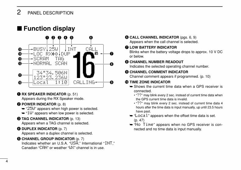
q RX SPEAKER INDICATOR (p. 51)Appears during the RX Speaker mode.
w POWER INDICATOR (p. 8) “2255WW” appears when high power is selected. “11WW” appears when low power is selected.
e TAG CHANNEL INDICATOR (p. 13)Appears when a TAG channel is selected.
r DUPLEX INDICATOR (p. 7)Appears when a duplex channel is selected.
t CHANNEL GROUP INDICATOR (p. 7)Indicates whether an U.S.A. “UUSSAA,” International “IINNTT,”Canadian “CCAANN” or weather “WWXX” channel is in use.
y CALL CHANNEL INDICATOR (pgs. 6, 9)Appears when the call channel is selected.
u LOW BATTERY INDICATORBlinks when the battery voltage drops to approx. 10 V DCor below.
i CHANNEL NUMBER READOUTIndicates the selected operating channel number.
o CHANNEL COMMENT INDICATORChannel comment appears if programmed. (p. 10)
!0 TIME ZONE INDICATOR Shows the current time data when a GPS receiver is
connected.• “????” may blink every 2 sec. instead of current time data when
the GPS current time data is invalid.• “????” may blink every 2 sec. instead of current time data 4
hours after the time data is input manually, up until 23.5 hourshave past.
“LLooccaall” appears when the offset time data is set.(p. 47)
“NNoo TTiimmee” appears when no GPS receiver is con-nected and no time data is input manually.
BUSY 25W INT CALLLOC RX DUPSCRAM TAGNORMAL SCAN
-34°34.506N123°23.236WLocal 1:10 CALLING
q w e r t y
!5
!4
!3
!1
!0
!2 i
o
u
5
2PANEL DESCRIPTION
2!1 POSITION INDICATOR Shows the GPS position data.
• “????” may blink every 2 sec. instead of position data when theGPS position data is invalid. In such a case, the last positiondata is held for up to 23.5 hours.
• “????” may blink every 2 sec. instead of position data 4 hoursafter the position data is input manually, up until 23.5 hourshave past.
“NNoo PPoossiittiioonn” appears when no GPS receiver isconnected and no position data is input manually.
!2 SCAN INDICATOR “PPRRII--SSCCAANN 1166” appears during Priority scan;
“NNOORRMMAALL SSCCAANN” appears during Normal scan. (p. 13) “DDUUAALL 1166” appears during Dualwatch; “TTRRII 1166” ap-
pears during Tri-watch. (p. 14)
!3 SCRAMBLER INDICATOR (p. 11)Appears when the voice scrambler function is activated.(only when the optional scrambler unit is installed.)
!4 LOCAL INDICATOR (p. 8)Appears when the Attenuator function is turned ON.
!5 BUSY/TRANSMIT INDICATOR (p. 8) “BBUUSSYY” appears when receiving a signal or when the
squelch opens. “TTXX” appears while transmitting.
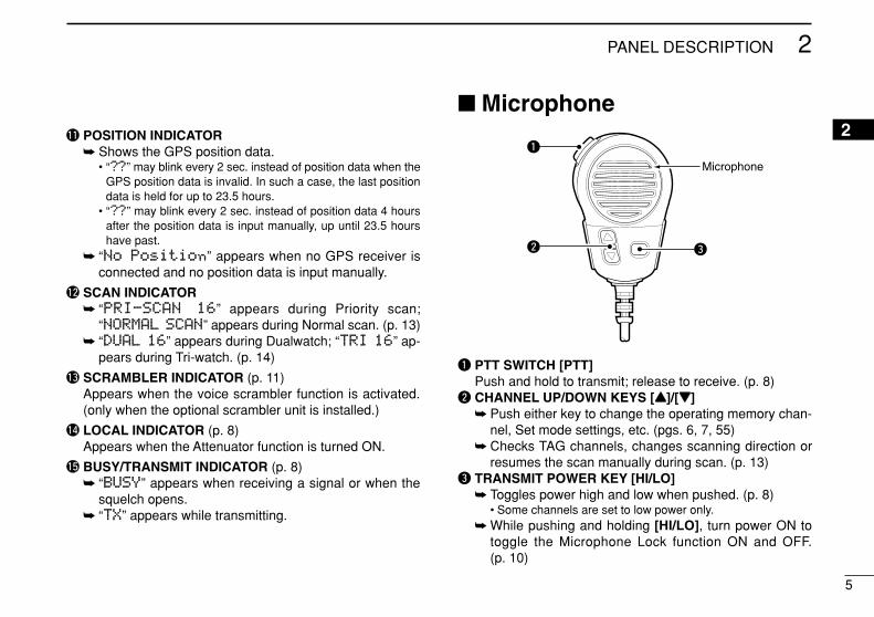
Microphone
q PTT SWITCH [PTT]Push and hold to transmit; release to receive. (p. 8)
w CHANNEL UP/DOWN KEYS [YY]/[ZZ] Push either key to change the operating memory chan-
nel, Set mode settings, etc. (pgs. 6, 7, 55) Checks TAG channels, changes scanning direction or
resumes the scan manually during scan. (p. 13)e TRANSMIT POWER KEY [HI/LO]
Toggles power high and low when pushed. (p. 8)• Some channels are set to low power only.
While pushing and holding [HI/LO], turn power ON totoggle the Microphone Lock function ON and OFF.(p. 10)
Microphone
w
q
e
6
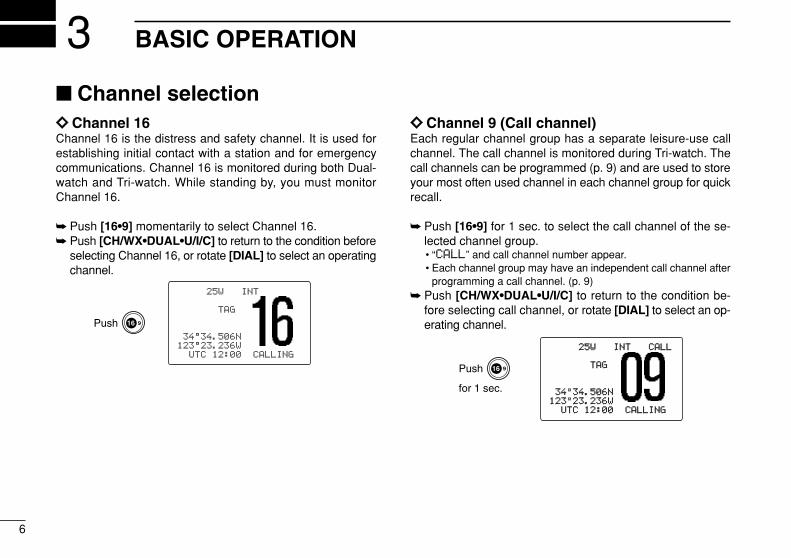
BASIC OPERATION3 Channel selectionïï Channel 16Channel 16 is the distress and safety channel. It is used forestablishing initial contact with a station and for emergencycommunications. Channel 16 is monitored during both Dual-watch and Tri-watch. While standing by, you must monitorChannel 16.
Push [16•9] momentarily to select Channel 16. Push [CH/WX•DUAL•U/I/C] to return to the condition before
selecting Channel 16, or rotate [DIAL] to select an operatingchannel.
ïï Channel 9 (Call channel)Each regular channel group has a separate leisure-use callchannel. The call channel is monitored during Tri-watch. Thecall channels can be programmed (p. 9) and are used to storeyour most often used channel in each channel group for quickrecall.
Push [16•9] for 1 sec. to select the call channel of the se-lected channel group.• “CCAALLLL” and call channel number appear.• Each channel group may have an independent call channel after
programming a call channel. (p. 9) Push [CH/WX•DUAL•U/I/C] to return to the condition be-
fore selecting call channel, or rotate [DIAL] to select an op-erating channel.
25W25W INTINT CALLCALL
TAGTAG
3434°34.506N34.506N123123°23.236W23.236W
UTCUTC 1212:00:00 CALLINGCALLING
Push
for 1 sec.
25W INT
TAG
34°34.506N123°23.236W
UTC 12:00 CALLING
Push
7
3BASIC OPERATION
3
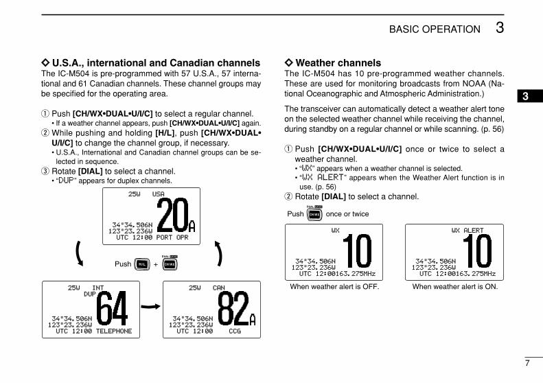
ïï U.S.A., international and Canadian channelsThe IC-M504 is pre-programmed with 57 U.S.A., 57 interna-tional and 61 Canadian channels. These channel groups maybe specified for the operating area.
q Push [CH/WX•DUAL•U/I/C] to select a regular channel.• If a weather channel appears, push [CH/WX•DUAL•U/I/C] again.
w While pushing and holding [H/L], push [CH/WX•DUAL•U/I/C] to change the channel group, if necessary.• U.S.A., International and Canadian channel groups can be se-
lected in sequence.e Rotate [DIAL] to select a channel.
• “DDUUPP” appears for duplex channels.
ïï Weather channelsThe IC-M504 has 10 pre-programmed weather channels.These are used for monitoring broadcasts from NOAA (Na-tional Oceanographic and Atmospheric Administration.)
The transceiver can automatically detect a weather alert toneon the selected weather channel while receiving the channel,during standby on a regular channel or while scanning. (p. 56)
q Push [CH/WX•DUAL•U/I/C] once or twice to select aweather channel.• “WWXX” appears when a weather channel is selected.• “WWXX AALLEERRTT” appears when the Weather Alert function is in
use. (p. 56)w Rotate [DIAL] to select a channel.
WXWX ALERTALERT
3434°34.506N34.506N123123°23.236W23.236W
UTCUTC 1212:00:00163163.275MHz.275MHz
WXWX
3434°34.506N34.506N123123°23.236W23.236W
UTCUTC 1212:00:00163163.275MHz.275MHz
Push once or twice
When weather alert is OFF. When weather alert is ON.
25W25W USAUSA
3434°34.506N34.506N123123°23.236W23.236W
UTCUTC 1212:00:00 PORTPORT OPROPR
25W25W INTINTDUPDUP
3434°34.506N34.506N123123°23.236W23.236W
UTCUTC 1212:00:00 TELEPHONETELEPHONE
25W25W CANCAN
3434°34.506N34.506N123123°23.236W23.236W
UTCUTC 1212:00:00 CCGCCG
Push +
8
3 BASIC OPERATION
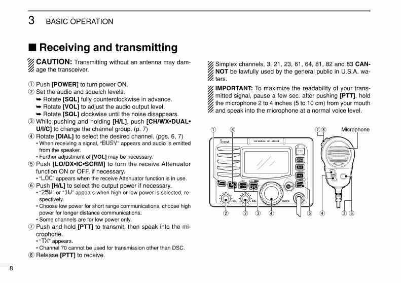
Receiving and transmittingCAUTION: Transmitting without an antenna may dam-age the transceiver.
q Push [POWER] to turn power ON.w Set the audio and squelch levels.
Rotate [SQL] fully counterclockwise in advance. Rotate [VOL] to adjust the audio output level. Rotate [SQL] clockwise until the noise disappears.
e While pushing and holding [H/L], push [CH/WX•DUAL•U/I/C] to change the channel group. (p. 7)
r Rotate [DIAL] to select the desired channel. (pgs. 6, 7)• When receiving a signal, “BBUUSSYY” appears and audio is emitted
from the speaker.• Further adjustment of [VOL] may be necessary.
t Push [LO/DX•IC•SCRM] to turn the receive Attenuatorfunction ON or OFF, if necessary.• “LLOOCC” appears when the receive Attenuator function is in use.
y Push [H/L] to select the output power if necessary.• “2255WW” or “11WW” appears when high or low power is selected, re-
spectively.• Choose low power for short range communications, choose high
power for longer distance communications.• Some channels are for low power only.
u Push and hold [PTT] to transmit, then speak into the mi-crophone.• “TTXX” appears.• Channel 70 cannot be used for transmission other than DSC.
i Release [PTT] to receive.
Simplex channels, 3, 21, 23, 61, 64, 81, 82 and 83 CAN-NOT be lawfully used by the general public in U.S.A. wa-ters.
IMPORTANT: To maximize the readability of your trans-mitted signal, pause a few sec. after pushing [PTT], holdthe microphone 2 to 4 inches (5 to 10 cm) from your mouthand speak into the microphone at a normal voice level.
t
Microphoneq y
reww
iu
r e y
9
3BASIC OPERATION
3
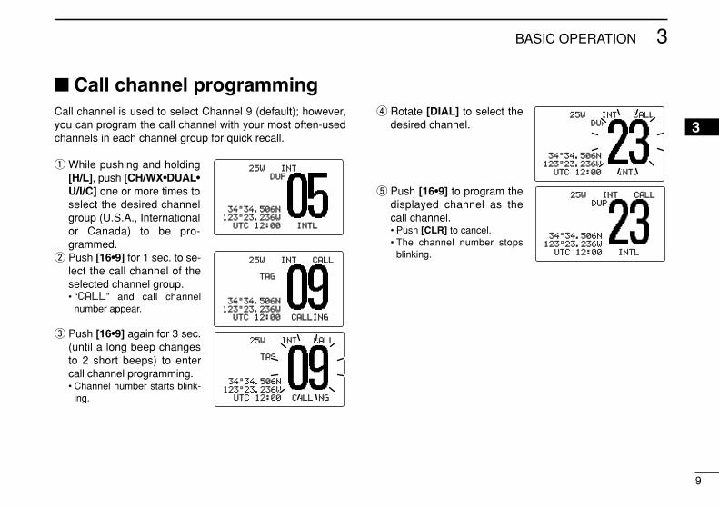
Call channel programmingCall channel is used to select Channel 9 (default); however,you can program the call channel with your most often-usedchannels in each channel group for quick recall.
q While pushing and holding[H/L], push [CH/WX•DUAL•U/I/C] one or more times toselect the desired channelgroup (U.S.A., Internationalor Canada) to be pro-grammed.
w Push [16•9] for 1 sec. to se-lect the call channel of theselected channel group.• “CCAALLLL” and call channel
number appear.
e Push [16•9] again for 3 sec.(until a long beep changesto 2 short beeps) to entercall channel programming.• Channel number starts blink-
ing.
r Rotate [DIAL] to select thedesired channel.
t Push [16•9] to program thedisplayed channel as thecall channel.• Push [CLR] to cancel.• The channel number stops
blinking.
25W25W INTINTDUPDUP
3434°34.506N34.506N123123°23.236W23.236W
UTCUTC 1212:00:00 INTLINTL
25W25W INTINT CALLCALL
TAGTAG
3434°34.506N34.506N123123°23.236W23.236W
UTCUTC 1212:00:00 CALLINGCALLING
25W25W INTINT CALLCALL
TAGTAG
3434°34.506N34.506N123123°23.236W23.236W
UTCUTC 1212:00:00 CALLINGCALLING
25W25W INTINT CALLCALLDUDUP
3434°34.506N34.506N123123°23.236W23.236W
UTCUTC 1212:00:00 INTLINTL
25W25W INTINT CALLCALLDUPDUP
3434°34.506N34.506N123123°23.236W23.236W
UTCUTC 1212:00:00 INTLINTL
10
3 BASIC OPERATION
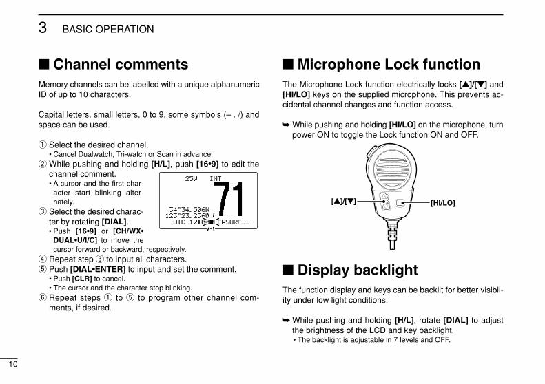
Channel commentsMemory channels can be labelled with a unique alphanumericID of up to 10 characters.
Capital letters, small letters, 0 to 9, some symbols (– . /) andspace can be used.
q Select the desired channel.• Cancel Dualwatch, Tri-watch or Scan in advance.
w While pushing and holding [H/L], push [16•9] to edit thechannel comment.• A cursor and the first char-
acter start blinking alter-nately.
e Select the desired charac-ter by rotating [DIAL].• Push [16•9] or [CH/WX•
DUAL•U/I/C] to move thecursor forward or backward, respectively.
r Repeat step e to input all characters.t Push [DIAL•ENTER] to input and set the comment.
• Push [CLR] to cancel.• The cursor and the character stop blinking.
y Repeat steps q to t to program other channel com-ments, if desired.
Microphone Lock functionThe Microphone Lock function electrically locks [Y]/[Z] and[HI/LO] keys on the supplied microphone. This prevents ac-cidental channel changes and function access.
While pushing and holding [HI/LO] on the microphone, turnpower ON to toggle the Lock function ON and OFF.
Display backlightThe function display and keys can be backlit for better visibil-ity under low light conditions.
While pushing and holding [H/L], rotate [DIAL] to adjustthe brightness of the LCD and key backlight.• The backlight is adjustable in 7 levels and OFF.
[HI/LO][Y]/[Z]
25W25W INTINT
3434°34.506N34.506N123123°23.236W23.236W
UTCUTC 1212:00:00PLEASURE__PLEASURE__
11
3BASIC OPERATION
3
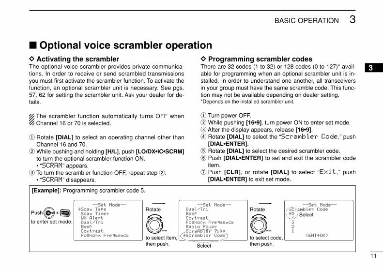
Optional voice scrambler operationDD Activating the scramblerThe optional voice scrambler provides private communica-tions. In order to receive or send scrambled transmissionsyou must first activate the scrambler function. To activate thefunction, an optional scrambler unit is necessary. See pgs.57, 62 for setting the scrambler unit. Ask your dealer for de-tails.
The scrambler function automatically turns OFF whenChannel 16 or 70 is selected.
q Rotate [DIAL] to select an operating channel other thanChannel 16 and 70.
w While pushing and holding [H/L], push [LO/DX•IC•SCRM]to turn the optional scrambler function ON.• “SSCCRRAAMM” appears.
e To turn the scrambler function OFF, repeat step w.• “SSCCRRAAMM” disappears.
DD Programming scrambler codesThere are 32 codes (1 to 32) or 128 codes (0 to 127)* avail-able for programming when an optional scrambler unit is in-stalled. In order to understand one another, all transceiversin your group must have the same scramble code. This func-tion may not be available depending on dealer setting.*Depends on the installed scrambler unit.
q Turn power OFF.w While pushing [16•9], turn power ON to enter set mode.e After the display appears, release [16•9].r Rotate [DIAL] to select the “SSccrraammbblleerr CCooddee,” push
[DIAL•ENTER].t Rotate [DIAL] to select the desired scrambler code.y Push [DIAL•ENTER] to set and exit the scrambler code
item.u Push [CLR], or rotate [DIAL] to select “EExxiitt,” push
[DIAL•ENTER] to exit set mode.
--Set Mode--Scrambler Code˘54321
<ENT˘OK>
--Set Mode--Dual/TriBeepContrastFoghorn FrequencyRadio PowerScrambler Type
˘Scrambler Code
--Set Mode--˘Scan TypeScan TimerWX AlertDual/TriBeepContrastFoghorn Frequency
+
to enter set mode.
Push
to select code,then push.
Rotate
to select item,then push.
Rotate
Select
Select
[Example]: Programming scrambler code 5.
12
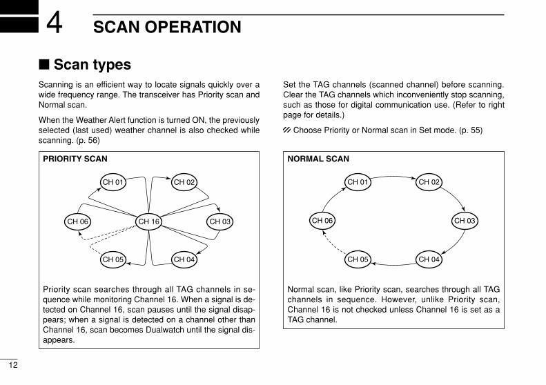
SCAN OPERATION4 Scan typesScanning is an efficient way to locate signals quickly over awide frequency range. The transceiver has Priority scan andNormal scan.
When the Weather Alert function is turned ON, the previouslyselected (last used) weather channel is also checked whilescanning. (p. 56)
Set the TAG channels (scanned channel) before scanning.Clear the TAG channels which inconveniently stop scanning,such as those for digital communication use. (Refer to rightpage for details.)
Choose Priority or Normal scan in Set mode. (p. 55)
PRIORITY SCAN
Priority scan searches through all TAG channels in se-quence while monitoring Channel 16. When a signal is de-tected on Channel 16, scan pauses until the signal disap-pears; when a signal is detected on a channel other thanChannel 16, scan becomes Dualwatch until the signal dis-appears.
CH 06
CH 01
CH 16
CH 02
CH 05 CH 04
CH 03
NORMAL SCAN
Normal scan, like Priority scan, searches through all TAGchannels in sequence. However, unlike Priority scan,Channel 16 is not checked unless Channel 16 is set as aTAG channel.
CH 01 CH 02
CH 06
CH 05 CH 04
CH 03
13
4SCAN OPERATION
4
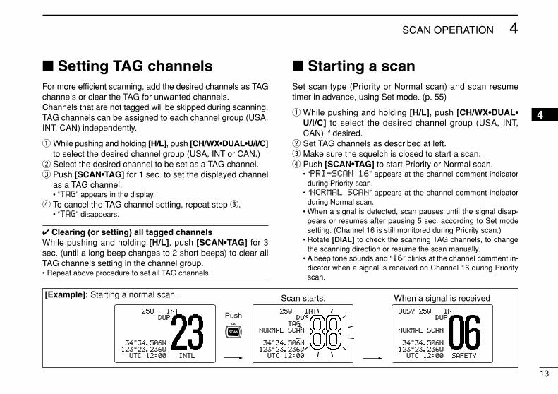
Setting TAG channelsFor more efficient scanning, add the desired channels as TAGchannels or clear the TAG for unwanted channels. Channels that are not tagged will be skipped during scanning.TAG channels can be assigned to each channel group (USA,INT, CAN) independently.
q While pushing and holding [H/L], push [CH/WX•DUAL•U/I/C]to select the desired channel group (USA, INT or CAN.)
w Select the desired channel to be set as a TAG channel.e Push [SCAN•TAG] for 1 sec. to set the displayed channel
as a TAG channel.• “TTAAGG” appears in the display.
r To cancel the TAG channel setting, repeat step e.• “TTAAGG” disappears.
Clearing (or setting) all tagged channelsWhile pushing and holding [H/L], push [SCAN•TAG] for 3sec. (until a long beep changes to 2 short beeps) to clear allTAG channels setting in the channel group.• Repeat above procedure to set all TAG channels.
Starting a scanSet scan type (Priority or Normal scan) and scan resumetimer in advance, using Set mode. (p. 55)
q While pushing and holding [H/L], push [CH/WX•DUAL•U/I/C] to select the desired channel group (USA, INT,CAN) if desired.
w Set TAG channels as described at left.e Make sure the squelch is closed to start a scan.r Push [SCAN•TAG] to start Priority or Normal scan.
• “PPRRII--SSCCAANN 1166” appears at the channel comment indicatorduring Priority scan.
• “NNOORRMMAALL SSCCAANN” appears at the channel comment indicatorduring Normal scan.
• When a signal is detected, scan pauses until the signal disap-pears or resumes after pausing 5 sec. according to Set modesetting. (Channel 16 is still monitored during Priority scan.)
• Rotate [DIAL] to check the scanning TAG channels, to changethe scanning direction or resume the scan manually.
• A beep tone sounds and “1166” blinks at the channel comment in-dicator when a signal is received on Channel 16 during Priorityscan.
Push
Scan starts. When a signal is received
25W25W INTINTDUPDUP
3434°34.506N34.506N123123°23.236W23.236W
UTCUTC 1212:00:00 INTLINTL
BUSYBUSY 25W25W INTINTDUPDUP
NORMALNORMAL SCANSCAN
3434°34.506N34.506N123123°23.236W23.236W
UTCUTC 1212:00:00 SAFETYSAFETY
25W25W INTINTDUPDUP
TAGTAGNORMALNORMAL SCANSCAN
3434°34.506N34.506N123123°23.236W23.236W
UTCUTC 1212:00:00
[Example]: Starting a normal scan.
14
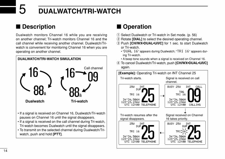
DUALWATCH/TRI-WATCH5 DescriptionDualwatch monitors Channel 16 while you are receiving on another channel; Tri-watch monitors Channel 16 and thecall channel while receiving another channel. Dualwatch/Tri-watch is convenient for monitoring Channel 16 when you areoperating on another channel.
Operationq Select Dualwatch or Tri-watch in Set mode. (p. 56)w Rotate [DIAL] to select the desired operating channel.e Push [CH/WX•DUAL•U/I/C] for 1 sec. to start Dualwatch
or Tri-watch.• “DDUUAALL 1166” appears during Dualwatch; “TTRRII 1166” appears dur-
ing Tri-watch.• A beep tone sounds when a signal is received on Channel 16.
r To cancel Dualwatch/Tri-watch, push [CH/WX•DUAL•U/I/C]again.
DUALWATCH/TRI-WATCH SIMULATION
• If a signal is received on Channel 16, Dualwatch/Tri-watchpauses on Channel 16 until the signal disappears.
• If a signal is received on the call channel during Tri-watch,Tri-watch becomes Dualwatch until the signal disappears.
• To transmit on the selected channel during Dualwatch/Tri-watch, push and hold [PTT].
Dualwatch Tri-watch
Call channel
[Example]: Operating Tri-watch on INT Channel 25
25W25W INTINTDUPDUP
TRITRI 1616
3434°34.506N34.506N123123°23.236W23.236W
UTCUTC 1212:00:00 TELEPHONETELEPHONE
BUSYBUSY 25W25W INTINT CALLCALL
TAGTAGTRITRI 1616
3434°34.506N34.506N123123°23.236W23.236W
UTCUTC 1212:00:00 CALLINGCALLING
Tri-watch starts. Signal is received on call channel.
BUSYBUSY 25W25W INTINTDUPDUP
TRITRI 1616
3434°34.506N34.506N123123°23.236W23.236W
UTCUTC 1212:00:00 TELEPHONETELEPHONE
Signal received on Channel 16 takes priority.
25W25W INTINTDUPDUP
TRITRI 1616
3434°34.506N34.506N123123°23.236W23.236W
UTCUTC 1212:00:00 TELEPHONETELEPHONE
Tri-watch resumes after the signal disappears.
15
6DSC OPERATION
56
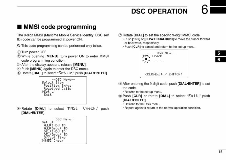
MMSI code programmingThe 9-digit MMSI (Maritime Mobile Service Identity: DSC selfID) code can be programmed at power ON.
This code programming can be performed only twice.
q Turn power OFF.w While pushing [MENU], turn power ON to enter MMSI
code programming condition.e After the display appears, release [MENU].r Push [MENU] again to enter the DSC menu.t Rotate [DIAL] to select “SSeett uupp,” push [DIAL•ENTER].
y Rotate [DIAL] to select “MMMMSSII CChheecckk,” push[DIAL•ENTER].
u Rotate [DIAL] to set the specific 9-digit MMSI code.• Push [16•9] or [CH/WX•DUAL•U/I/C] to move the cursor forward
or backward, respectively.• Push [CLR] to cancel and return to the set up menu.
i After entering the 9-digit code, push [DIAL•ENTER] to setthe code.• Returns to the set up menu.
o Push [CLR] or rotate [DIAL] to select “EExxiitt,” push[DIAL•ENTER].• Returns to the DSC menu.• Repeat again to return to the normal operation condition.
--DSC--DSC Menu--Menu--MMSI CheckMMSI Check__________________
<CLR<CLR˘ExitExit / ENTENT˘OK>OK>
--DSC--DSC Menu--Menu--SetSet upupAdd:INDVAdd:INDV IDIDAdd:GroupAdd:Group IDIDDEL:INDVDEL:INDV IDIDDEL:GroupDEL:Group IDIDOffsetOffset TimeTime
˘MMSIMMSI CheckCheck
--DSC--DSC Menu--Menu--SelectSelect ItemItemPositionPosition InputInputReceivedReceived CallsCalls
˘SetSet upupExitExit
16
6 DSC OPERATION
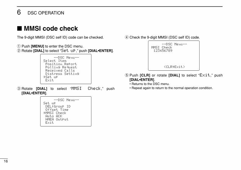
MMSI code checkThe 9-digit MMSI (DSC self ID) code can be checked.
q Push [MENU] to enter the DSC menu.w Rotate [DIAL] to select “SSeett uupp,” push [DIAL•ENTER].
e Rotate [DIAL] to select “MMMMSSII CChheecckk,” push [DIAL•ENTER].
r Check the 9-digit MMSI (DSC self ID) code.
t Push [CLR] or rotate [DIAL] to select “EExxiitt,” push [DIAL•ENTER].• Returns to the DSC menu.• Repeat again to return to the normal operation condition.
--DSC Menu--MMSI Check123456789
<CLR˘Exit>
--DSC Menu--Set upDEL:Group IDOffset Time
˘MMSI CheckAuto ACKNMEA OutputExit
--DSC Menu--Select ItemPosition ReportPolling RequestReceived CallsDistress Setting
˘Set upExit
17
6DSC OPERATION
6
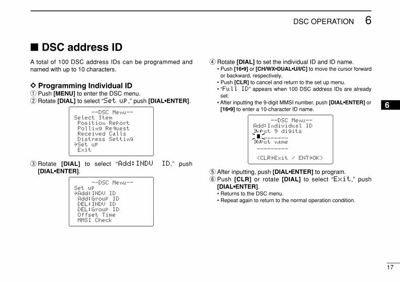
DSC address IDA total of 100 DSC address IDs can be programmed andnamed with up to 10 characters.
DD Programming Individual IDq Push [MENU] to enter the DSC menu.w Rotate [DIAL] to select “SSeett uupp,” push [DIAL•ENTER].
e Rotate [DIAL] to select “AAdddd::IINNDDVV IIDD,” push [DIAL•ENTER].
r Rotate [DIAL] to set the individual ID and ID name.• Push [16•9] or [CH/WX•DUAL•U/I/C] to move the cursor forward
or backward, respectively.• Push [CLR] to cancel and return to the set up menu.• “FFuullll IIDD” appears when 100 DSC address IDs are already
set.• After inputting the 9-digit MMSI number, push [DIAL•ENTER] or
[16•9] to enter a 10-character ID name.
t After inputting, push [DIAL•ENTER] to program.y Push [CLR] or rotate [DIAL] to select “EExxiitt,” push
[DIAL•ENTER].• Returns to the DSC menu.• Repeat again to return to the normal operation condition.
--DSC Menu--Add:Individual IDInput 9 digits_________
Input name_________
<CLR˘Exit / ENT˘OK>
--DSC Menu--Set up˘Add:INDV IDAdd:Group IDDEL:INDV IDDEL:Group IDOffset TimeMMSI Check
--DSC Menu--Select ItemPosition ReportPolling RequestReceived CallsDistress Setting
˘Set upExit
18
6 DSC OPERATION
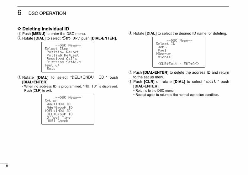
DD Deleting Individual IDq Push [MENU] to enter the DSC menu.w Rotate [DIAL] to select “SSeett uupp,” push [DIAL•ENTER].
e Rotate [DIAL] to select “DDEELL::IINNDDVV IIDD,” push [DIAL•ENTER].• When no address ID is programmed, “NNoo IIDD” is displayed.
Push [CLR] to exit.
r Rotate [DIAL] to select the desired ID name for deleting.
t Push [DIAL•ENTER] to delete the address ID and returnto the set up menu.
y Push [CLR] or rotate [DIAL] to select “EExxiitt,” push [DIAL•ENTER].• Returns to the DSC menu.• Repeat again to return to the normal operation condition.
--DSC Menu--Select IDJohnPaul
˘GeorgeMichael
<CLR˘Exit / ENT˘OK>
--DSC Menu--Set upAdd:INDV IDAdd:Group ID
˘DEL:INDV IDDEL:Group IDOffset TimeMMSI Check
--DSC Menu--Select ItemPosition ReportPolling RequestReceived CallsDistress Setting
˘Set upExit
19
6DSC OPERATION
6
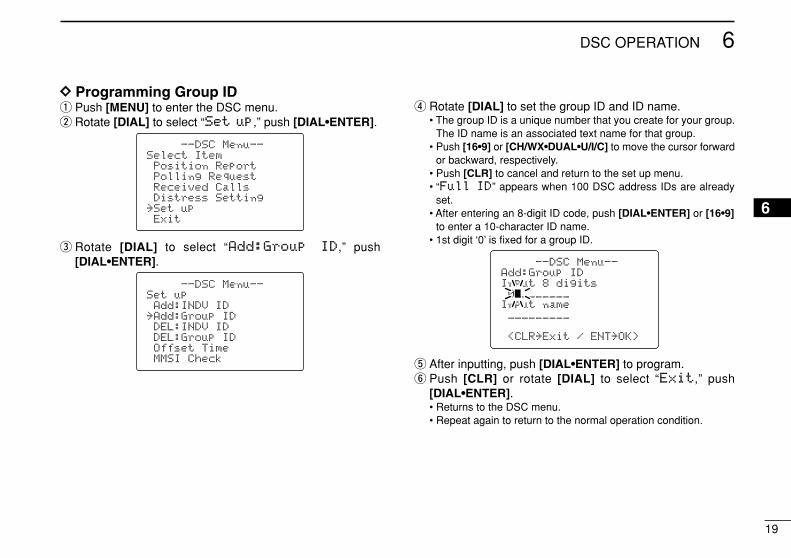
DD Programming Group IDq Push [MENU] to enter the DSC menu.w Rotate [DIAL] to select “SSeett uupp,” push [DIAL•ENTER].
e Rotate [DIAL] to select “AAdddd::GGrroouupp IIDD,” push [DIAL•ENTER].
r Rotate [DIAL] to set the group ID and ID name.• The group ID is a unique number that you create for your group.
The ID name is an associated text name for that group.• Push [16•9] or [CH/WX•DUAL•U/I/C] to move the cursor forward
or backward, respectively.• Push [CLR] to cancel and return to the set up menu.• “FFuullll IIDD” appears when 100 DSC address IDs are already
set.• After entering an 8-digit ID code, push [DIAL•ENTER] or [16•9]
to enter a 10-character ID name.• 1st digit ‘0’ is fixed for a group ID.
t After inputting, push [DIAL•ENTER] to program.y Push [CLR] or rotate [DIAL] to select “EExxiitt,” push
[DIAL•ENTER].• Returns to the DSC menu.• Repeat again to return to the normal operation condition.
--DSC Menu--Add:Group IDInput 8 digits0________
Input name_________
<CLR˘Exit / ENT˘OK>
--DSC Menu--Set upAdd:INDV ID
˘Add:Group IDDEL:INDV IDDEL:Group IDOffset TimeMMSI Check
--DSC Menu--Select ItemPosition ReportPolling RequestReceived CallsDistress Setting
˘Set upExit
20
6 DSC OPERATION
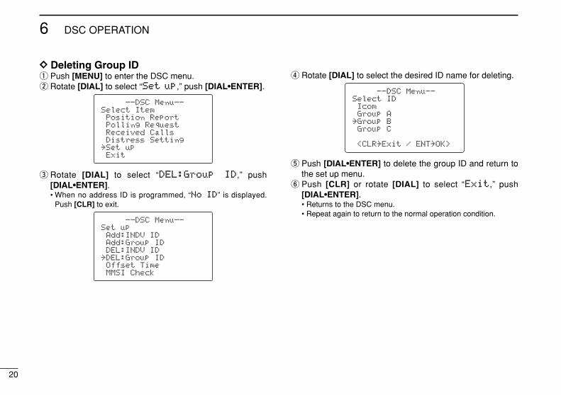
DD Deleting Group IDq Push [MENU] to enter the DSC menu.w Rotate [DIAL] to select “SSeett uupp,” push [DIAL•ENTER].
e Rotate [DIAL] to select “DDEELL::GGrroouupp IIDD,” push [DIAL•ENTER].• When no address ID is programmed, “NNoo IIDD” is displayed.
Push [CLR] to exit.
r Rotate [DIAL] to select the desired ID name for deleting.
t Push [DIAL•ENTER] to delete the group ID and return tothe set up menu.
y Push [CLR] or rotate [DIAL] to select “EExxiitt,” push [DIAL•ENTER].• Returns to the DSC menu.• Repeat again to return to the normal operation condition.
--DSC Menu--Select IDIcomGroup A
˘Group BGroup C
<CLR˘Exit / ENT˘OK>
--DSC Menu--Set upAdd:INDV IDAdd:Group IDDEL:INDV ID
˘DEL:Group IDOffset TimeMMSI Check
--DSC Menu--Select ItemPosition ReportPolling RequestReceived CallsDistress Setting
˘Set upExit
21
6DSC OPERATION
6
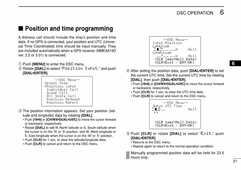
Position and time programmingA distress call should include the ship’s position and timedata. If no GPS is connected, your position and UTC (Univer-sal Time Coordinated) time should be input manually. Theyare included automatically when a GPS receiver (NMEA0183ver. 2.0 or 3.01) is connected.
q Push [MENU] to enter the DSC menu.w Rotate [DIAL] to select “PPoossiittiioonn IInnppuutt,” and push
[DIAL•ENTER].
e The position information appears. Set your position (lati-tude and longitude) data by rotating [DIAL].• Push [16•9] or [CH/WX•DUAL•U/I/C] to move the cursor forward
or backward, respectively.• Rotate [DIAL] to edit N; North latitude or S; South latitude when
the cursor is on the ‘N’ or ‘S’ position, and W; West longitude orE; East longitude when the cursor is on the ‘W’ or ‘E’ position.
• Push [CLR] for 1 sec. to clear the latitude/longitude data.• Push [CLR] to cancel and return to the DSC menu.
r After setting the position data, push [DIAL•ENTER] to setthe current UTC time. Set the current UTC time by rotating[DIAL], then push [DIAL•ENTER].• Push [16•9] or [CH/WX•DUAL•U/I/C] to move the cursor forward
or backward, respectively.• Push [CLR] for 1 sec. to clear the UTC time data.• Push [CLR] to cancel and return to the DSC menu.
t Push [CLR] or rotate [DIAL] to select “EExxiitt,” push[DIAL•ENTER].• Returns to the DSC menu.• Repeat again to return to the normal operation condition.
Manually programmed position data will be held for 23.5hours only.
--DSC Menu--Input UTC Time__:__ Null
<CLR<CLR 1sec1sec˘NullNull Data>Data><CLR<CLR˘ExitExit / ENTENT˘OK>OK>
--DSC Menu--Input PositionLatitude
__°__.___N NullLongitude
__°__.___W Null<CLR<CLR 1sec1sec˘NullNull Data>Data><CLR<CLR˘ExitExit / ENTENT˘OK>OK>
--DSC Menu--Select Item˘Position InputIndividual CallGroup CallAll Ships CallPosition RequestPosition Report
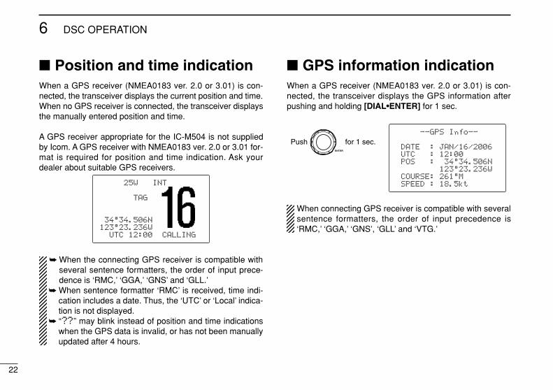
Position and time indicationWhen a GPS receiver (NMEA0183 ver. 2.0 or 3.01) is con-nected, the transceiver displays the current position and time.When no GPS receiver is connected, the transceiver displaysthe manually entered position and time.
A GPS receiver appropriate for the IC-M504 is not suppliedby Icom. A GPS receiver with NMEA0183 ver. 2.0 or 3.01 for-mat is required for position and time indication. Ask yourdealer about suitable GPS receivers.
When the connecting GPS receiver is compatible withseveral sentence formatters, the order of input prece-dence is ‘RMC,’ ‘GGA,’ ‘GNS’ and ‘GLL.’
When sentence formatter ‘RMC’ is received, time indi-cation includes a date. Thus, the ‘UTC’ or ‘Local’ indica-tion is not displayed.
“????” may blink instead of position and time indicationswhen the GPS data is invalid, or has not been manuallyupdated after 4 hours.
GPS information indicationWhen a GPS receiver (NMEA0183 ver. 2.0 or 3.01) is con-nected, the transceiver displays the GPS information afterpushing and holding [DIAL•ENTER] for 1 sec.
When connecting GPS receiver is compatible with severalsentence formatters, the order of input precedence is‘RMC,’ ‘GGA,’ ‘GNS’, ‘GLL’ and ‘VTG.’
--GPS Info--
DATE : JAN/16/2006UTC : 12:00POS : 34°34.506N
123°23.236WCOURSE: 261°MSPEED : 18.5kt
Push for 1 sec.
25W INT
TAG
34°34.506N123°23.236W
UTC 12:00 CALLING
22
6 DSC OPERATION
23
6DSC OPERATION
6
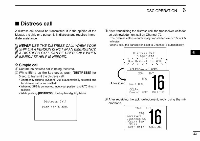
Distress callA distress call should be transmitted, if in the opinion of theMaster, the ship or a person is in distress and requires imme-diate assistance.
NEVER USE THE DISTRESS CALL WHEN YOURSHIP OR A PERSON IS NOT IN AN EMERGENCY.A DISTRESS CALL CAN BE USED ONLY WHENIMMEDIATE HELP IS NEEDED.
DD Simple callq Confirm no distress call is being received.w While lifting up the key cover, push [DISTRESS] for
5 sec. to transmit the distress call.• Emergency channel (Channel 70) is automatically selected and
the distress call is transmitted.• When no GPS is connected, input your position and UTC time, if
possible.• While pushing [DISTRESS], the key backlighting blinks.
e After transmitting the distress call, the transceiver waits foran acknowledgment call on Channel 70.• The distress call is automatically transmitted every 3.5 to 4.5
minutes.• After 2 sec., the transceiver is set to Channel 16 automatically.
r After receiving the acknowledgment, reply using the mi-crophone.
25W INT
TAGReceivedDistressACK<Osaka Bay<CLR˘Beep Off> CALLING
Distress CallTX Complete
Now Waiting for ACK
<CLR<CLR˘CancelCancel ACK>ACK>
After 2 sec.
25W INT
TAG
Wait ACK
<CLR˘Cancel ACK> CALLING
Distress Call
Push for 5 sec.
24
6 DSC OPERATION
A distress alert contains (default);• Nature of distress : Undesignated distress• Position data : GPS or manual input position data held
for 23.5 hrs or until the power is turnedOFF.
The distress call is repeated every 3.5–4.5 min., until re-ceiving an ‘acknowledgement.’
Push [CLR] to cancel the ‘Call repeat’ mode. “??” may blink instead of position and time indications
when the GPS data is invalid, or has not been manuallyupdated after 4 hours.
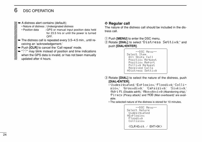
DD Regular callThe nature of the distress call should be included in the dis-tress call.
q Push [MENU] to enter the DSC menu.w Rotate [DIAL] to select “DDiissttrreessss SSeettttiinngg,” and
push [DIAL•ENTER].
e Rotate [DIAL] to select the nature of the distress, push[DIAL•ENTER].• ‘UUnnddeessiiggnnaatteedd,’ ‘EExxpplloossiioonn,’ ‘FFllooooddiinngg,’ ‘CCoollllii--ssiioonn,’ ‘GGrroouunnddiinngg,’ ‘CCaappssiizziinngg,’ ‘SSiinnkkiinngg,’‘AAddrriifftt (Disable adrift),’ ‘AAbbaannddoonniinngg (Abandoning ship),’‘PPiirraaccyy (Piracy attack)’ and ‘MMOOBB (Man overboard)’ are avail-able.
• The selected nature of the distress is stored for 10 minutes.
--DSC Menu--Select NatureUndesignated
˘ExplosionFloodingCollision
<CLR<CLR˘ExitExit / ENTENT˘OK>OK>
--DSC Menu--Select ItemAll Ships CallPosition RequestPosition ReportPolling RequestReceived Calls
˘Distress Setting
25
6DSC OPERATION
6
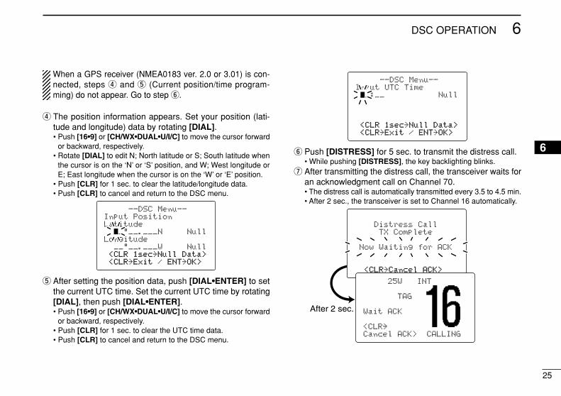
When a GPS receiver (NMEA0183 ver. 2.0 or 3.01) is con-nected, steps r and t (Current position/time program-ming) do not appear. Go to step y.
r The position information appears. Set your position (lati-tude and longitude) data by rotating [DIAL].• Push [16•9] or [CH/WX•DUAL•U/I/C] to move the cursor forward
or backward, respectively.• Rotate [DIAL] to edit N; North latitude or S; South latitude when
the cursor is on the ‘N’ or ‘S’ position, and W; West longitude orE; East longitude when the cursor is on the ‘W’ or ‘E’ position.
• Push [CLR] for 1 sec. to clear the latitude/longitude data.• Push [CLR] to cancel and return to the DSC menu.
t After setting the position data, push [DIAL•ENTER] to setthe current UTC time. Set the current UTC time by rotating[DIAL], then push [DIAL•ENTER].• Push [16•9] or [CH/WX•DUAL•U/I/C] to move the cursor forward
or backward, respectively.• Push [CLR] for 1 sec. to clear the UTC time data.• Push [CLR] to cancel and return to the DSC menu.
y Push [DISTRESS] for 5 sec. to transmit the distress call.• While pushing [DISTRESS], the key backlighting blinks.
u After transmitting the distress call, the transceiver waits foran acknowledgment call on Channel 70.• The distress call is automatically transmitted every 3.5 to 4.5 min.• After 2 sec., the transceiver is set to Channel 16 automatically.
Distress CallTX Complete
Now Waiting for ACK
<CLR<CLR˘CancelCancel ACK>ACK>
After 2 sec.
25W INT
TAG
Wait ACK
<CLR˘Cancel ACK> CALLING
--DSC Menu--Input UTC Time__:__ Null
<CLR<CLR 1sec1sec˘NullNull Data>Data><CLR<CLR˘ExitExit / ENTENT˘OK>OK>
--DSC Menu--Input PositionLatitude
__°__.___N NullLongitude
__°__.___W Null<CLR<CLR 1sec1sec˘NullNull Data>Data><CLR<CLR˘ExitExit / ENTENT˘OK>OK>
26
6 DSC OPERATION
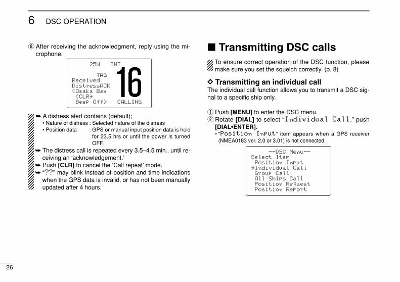
i After receiving the acknowledgment, reply using the mi-crophone.
A distress alert contains (default);• Nature of distress : Selected nature of the distress• Position data : GPS or manual input position data is held
for 23.5 hrs or until the power is turnedOFF.
The distress call is repeated every 3.5–4.5 min., until re-ceiving an ‘acknowledgement.’
Push [CLR] to cancel the ‘Call repeat’ mode. “????” may blink instead of position and time indications
when the GPS data is invalid, or has not been manuallyupdated after 4 hours.
Transmitting DSC callsTo ensure correct operation of the DSC function, pleasemake sure you set the squelch correctly. (p. 8)
DD Transmitting an individual callThe individual call function allows you to transmit a DSC sig-nal to a specific ship only.
q Push [MENU] to enter the DSC menu.w Rotate [DIAL] to select “IInnddiivviidduuaall CCaallll,” push
[DIAL•ENTER].• “PPoossiittiioonn IInnppuutt” item appears when a GPS receiver
(NMEA0183 ver. 2.0 or 3.01) is not connected.
--DSC Menu--Select ItemPosition Input
˘Individual CallGroup CallAll Ships CallPosition RequestPosition Report
25W INT
TAGReceivedDistressACK<Osaka Bay<CLR˘Beep Off> CALLING
27
6DSC OPERATION
6
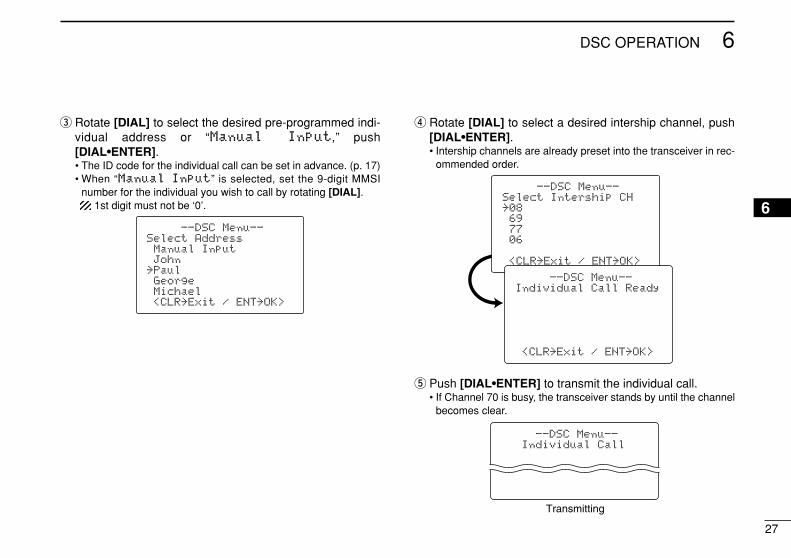
e Rotate [DIAL] to select the desired pre-programmed indi-vidual address or “MMaannuuaall IInnppuutt,” push[DIAL•ENTER].• The ID code for the individual call can be set in advance. (p. 17)• When “MMaannuuaall IInnppuutt” is selected, set the 9-digit MMSI
number for the individual you wish to call by rotating [DIAL].1st digit must not be ‘0’.
r Rotate [DIAL] to select a desired intership channel, push[DIAL•ENTER].• Intership channels are already preset into the transceiver in rec-
ommended order.
t Push [DIAL•ENTER] to transmit the individual call.• If Channel 70 is busy, the transceiver stands by until the channel
becomes clear.
--DSC Menu--Individual Call
Transmitting
--DSC Menu--Select Intership CH˘08697706
<CLR˘Exit / ENT˘OK>
--DSC Menu--Individual Call Ready
<CLR˘Exit / ENT˘OK>
--DSC Menu--Select AddressManual InputJohn
˘PaulGeorgeMichael<CLR˘Exit / ENT˘OK>
28
6 DSC OPERATION
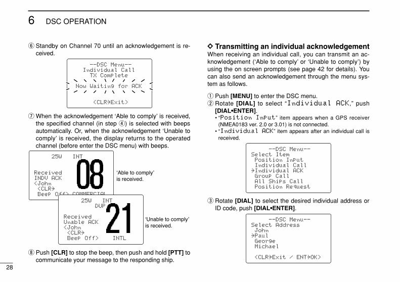
y Standby on Channel 70 until an acknowledgement is re-ceived.
u When the acknowledgement ‘Able to comply’ is received,the specified channel (in step r) is selected with beepsautomatically. Or, when the acknowledgement ‘Unable tocomply’ is received, the display returns to the operatedchannel (before enter the DSC menu) with beeps.
i Push [CLR] to stop the beep, then push and hold [PTT] tocommunicate your message to the responding ship.
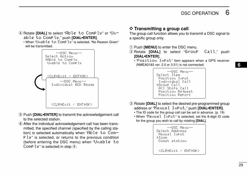
DD Transmitting an individual acknowledgementWhen receiving an individual call, you can transmit an ac-knowledgement (‘Able to comply’ or ‘Unable to comply’) byusing the on screen prompts (see page 42 for details). Youcan also send an acknowledgement through the menu sys-tem as follows.
q Push [MENU] to enter the DSC menu.w Rotate [DIAL] to select “IInnddiivviidduuaall AACCKK,” push
[DIAL•ENTER].• “PPoossiittiioonn IInnppuutt” item appears when a GPS receiver
(NMEA0183 ver. 2.0 or 3.01) is not connected.• “IInnddiivviidduuaall AACCKK” item appears after an individual call is
received.
e Rotate [DIAL] to select the desired individual address orID code, push [DIAL•ENTER].
--DSC Menu--Select AddressJohn
˘PaulGeorgeMichael
<CLR˘Exit / ENT˘OK>
--DSC Menu--Select ItemPosition InputIndividual Call
˘Individual ACKGroup CallAll Ships CallPosition Request
25W INT
ReceivedINDV ACK<John<CLR˘Beep Off> COMMERCIAL
25W INTDUP
ReceivedUnable ACK<John<CLR˘Beep Off> INTL
--DSC Menu--Individual Call
TX Complete
Now Waiting for ACK
<CLR˘Exit>
29
6DSC OPERATION
6
r Rotate [DIAL] to select “AAbbllee ttoo CCoommppllyy” or “UUnn--aabbllee ttoo CCoommppllyy,” push [DIAL•ENTER].• When “UUnnaabbllee ttoo CCoommppllyy” is selected, “No Reason Given”
will be transmitted.
t Push [DIAL•ENTER] to transmit the acknowledgement callto the selected station.
y After the individual acknowledgement call has been trans-mitted, the specified channel (specified by the calling sta-tion) is selected automatically when “AAbbllee ttoo CCoomm--
ppllyy” is selected, or returns to the previous condition(before entering the DSC menu) when “UUnnaabbllee ttooCCoommppllyy” is selected in step r.
DD Transmitting a group callThe group call function allows you to transmit a DSC signal toa specific group only.
q Push [MENU] to enter the DSC menu.w Rotate [DIAL] to select “GGrroouupp CCaallll,” push
[DIAL•ENTER].• “PPoossiittiioonn IInnppuutt” item appears when a GPS receiver
(NMEA0183 ver. 2.0 or 3.01) is not connected.
e Rotate [DIAL] to select the desired pre-programmed groupaddress or “MMaannuuaall IInnppuutt,” push [DIAL•ENTER].• The ID code for the group call can be set in advance. (p. 19)• When “MMaannuuaall IInnppuutt” is selected, set the 8-digit ID code
for the group you wish to call by rotating [DIAL].
--DSC Menu--Select AddressManual Input
˘IcomCoast station
<CLR˘Exit / ENT˘OK>
--DSC Menu--Select ItemPosition InputIndividual Call
˘Group CallAll Ships CallPosition RequestPosition Report
--DSC Menu--Select Action˘Able to ComplyUnable to Comply
<CLR˘Exit / ENT˘OK>
--DSC Menu--Individual ACK Ready
<CLR˘Exit / ENT˘OK>
30
6 DSC OPERATION
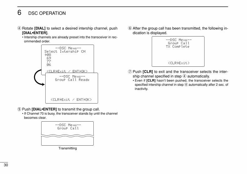
r Rotate [DIAL] to select a desired intership channel, push[DIAL•ENTER].• Intership channels are already preset into the transceiver in rec-
ommended order.
t Push [DIAL•ENTER] to transmit the group call.• If Channel 70 is busy, the transceiver stands by until the channel
becomes clear.
y After the group call has been transmitted, the following in-dication is displayed.
u Push [CLR] to exit and the transceiver selects the inter-ship channel specified in step r automatically.• Even if [CLR] hasn’t been pushed, the transceiver selects the
specified intership channel in step r automatically after 2 sec. ofinactivity.
--DSC Menu--Group Call
TX Complete
<CLR˘Exit>
--DSC Menu--Group Call
Transmitting
--DSC Menu--Select Intership CH˘08697706
<CLR˘Exit / ENT˘OK>
--DSC Menu--Group Call Ready
<CLR˘Exit / ENT˘OK>
31
6DSC OPERATION
6
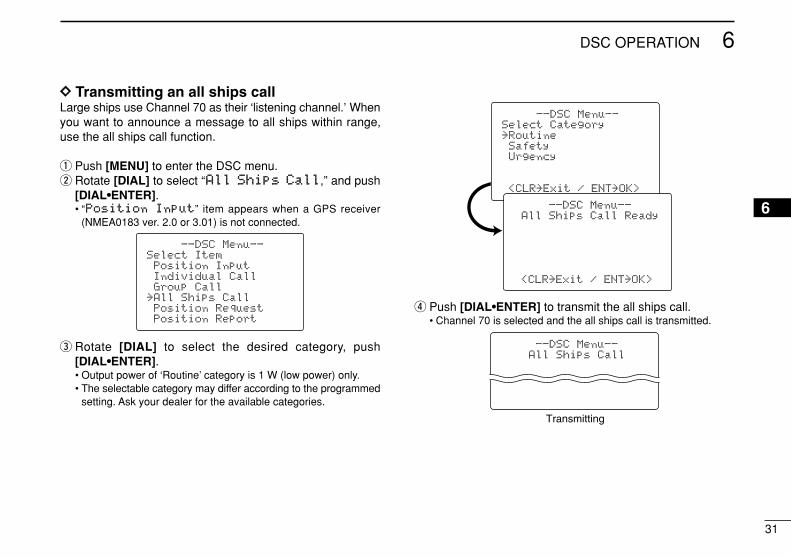
DD Transmitting an all ships callLarge ships use Channel 70 as their ‘listening channel.’ Whenyou want to announce a message to all ships within range,use the all ships call function.
q Push [MENU] to enter the DSC menu.w Rotate [DIAL] to select “AAllll SShhiippss CCaallll,” and push
[DIAL•ENTER].• “PPoossiittiioonn IInnppuutt” item appears when a GPS receiver
(NMEA0183 ver. 2.0 or 3.01) is not connected.
e Rotate [DIAL] to select the desired category, push[DIAL•ENTER].• Output power of ‘Routine’ category is 1 W (low power) only.• The selectable category may differ according to the programmed
setting. Ask your dealer for the available categories.
r Push [DIAL•ENTER] to transmit the all ships call.• Channel 70 is selected and the all ships call is transmitted.
--DSC Menu--All Ships Call
Transmitting
--DSC Menu--Select Category˘RoutineSafetyUrgency
<CLR˘Exit / ENT˘OK>
--DSC Menu--All Ships Call Ready
<CLR˘Exit / ENT˘OK>
--DSC Menu--Select ItemPosition InputIndividual CallGroup Call
˘All Ships CallPosition RequestPosition Report
32
6 DSC OPERATION
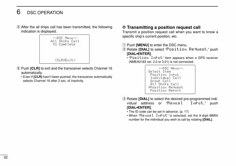
t After the all ships call has been transmitted, the followingindication is displayed.
y Push [CLR] to exit and the transceiver selects Channel 16automatically.• Even if [CLR] hasn’t been pushed, the transceiver automatically
selects Channel 16 after 2 sec. of inactivity.
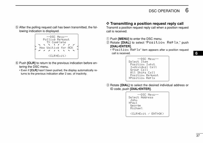
DD Transmitting a position request callTransmit a position request call when you want to know aspecific ship’s current position, etc.
q Push [MENU] to enter the DSC menu.w Rotate [DIAL] to select “PPoossiittiioonn RReeqquueesstt,” push
[DIAL•ENTER].• “PPoossiittiioonn IInnppuutt” item appears when a GPS receiver
(NMEA0183 ver. 2.0 or 3.01) is not connected.
e Rotate [DIAL] to select the desired pre-programmed indi-vidual address or “MMaannuuaall IInnppuutt,” push[DIAL•ENTER].• The ID code can be set in advance. (p. 17)• When “MMaannuuaall IInnppuutt” is selected, set the 9-digit MMSI
number for the individual you wish to call by rotating [DIAL].
--DSC Menu--Select ItemPosition InputIndividual CallGroup CallAll Ships Call
˘Position RequestPosition Report
--DSC Menu--All Ships CallTX Complete
<CLR˘Exit>
33
6DSC OPERATION
6
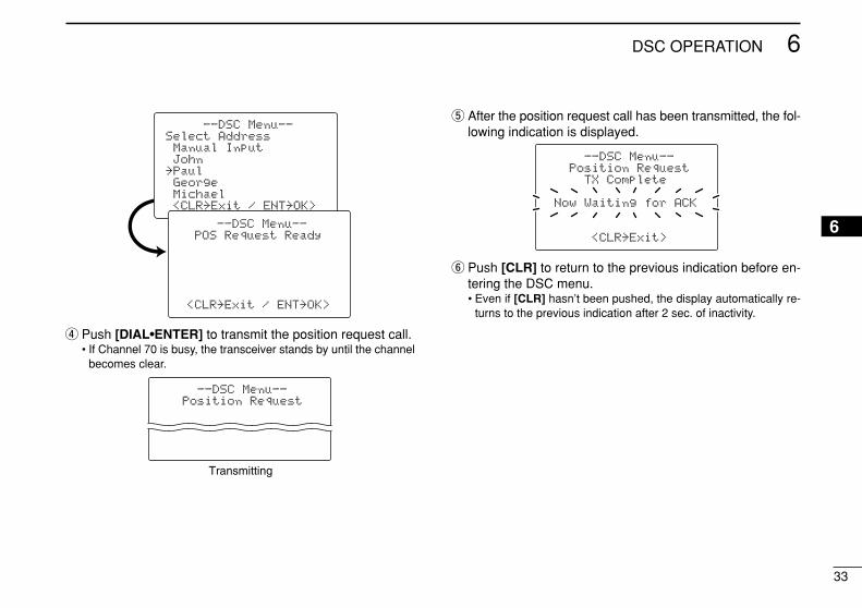
r Push [DIAL•ENTER] to transmit the position request call.• If Channel 70 is busy, the transceiver stands by until the channel
becomes clear.
t After the position request call has been transmitted, the fol-lowing indication is displayed.
y Push [CLR] to return to the previous indication before en-tering the DSC menu.• Even if [CLR] hasn’t been pushed, the display automatically re-
turns to the previous indication after 2 sec. of inactivity.
--DSC Menu--Position Request
TX Complete
Now Waiting for ACK
<CLR˘Exit>
--DSC Menu--Position Request
Transmitting
--DSC Menu--Select AddressManual InputJohn
˘PaulGeorgeMichael<CLR˘Exit / ENT˘OK>
--DSC Menu--POS Request Ready
<CLR˘Exit / ENT˘OK>
34
6 DSC OPERATION
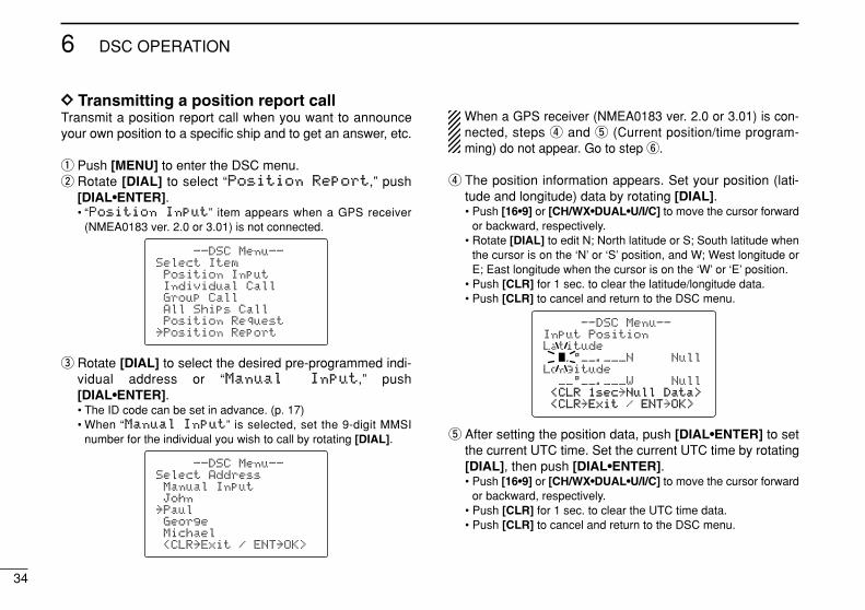
DD Transmitting a position report callTransmit a position report call when you want to announceyour own position to a specific ship and to get an answer, etc.
q Push [MENU] to enter the DSC menu.w Rotate [DIAL] to select “PPoossiittiioonn RReeppoorrtt,” push
[DIAL•ENTER].• “PPoossiittiioonn IInnppuutt” item appears when a GPS receiver
(NMEA0183 ver. 2.0 or 3.01) is not connected.
e Rotate [DIAL] to select the desired pre-programmed indi-vidual address or “MMaannuuaall IInnppuutt,” push[DIAL•ENTER].• The ID code can be set in advance. (p. 17)• When “MMaannuuaall IInnppuutt” is selected, set the 9-digit MMSI
number for the individual you wish to call by rotating [DIAL].
When a GPS receiver (NMEA0183 ver. 2.0 or 3.01) is con-nected, steps r and t (Current position/time program-ming) do not appear. Go to step y.
r The position information appears. Set your position (lati-tude and longitude) data by rotating [DIAL].• Push [16•9] or [CH/WX•DUAL•U/I/C] to move the cursor forward
or backward, respectively.• Rotate [DIAL] to edit N; North latitude or S; South latitude when
the cursor is on the ‘N’ or ‘S’ position, and W; West longitude orE; East longitude when the cursor is on the ‘W’ or ‘E’ position.
• Push [CLR] for 1 sec. to clear the latitude/longitude data.• Push [CLR] to cancel and return to the DSC menu.
t After setting the position data, push [DIAL•ENTER] to setthe current UTC time. Set the current UTC time by rotating[DIAL], then push [DIAL•ENTER].• Push [16•9] or [CH/WX•DUAL•U/I/C] to move the cursor forward
or backward, respectively.• Push [CLR] for 1 sec. to clear the UTC time data.• Push [CLR] to cancel and return to the DSC menu.
--DSC Menu--Input PositionLatitude
__°__.___N NullLongitude
__°__.___W Null<CLR<CLR 1sec1sec˘NullNull Data>Data><CLR<CLR˘ExitExit / ENTENT˘OK>OK>
--DSC Menu--Select AddressManual InputJohn
˘PaulGeorgeMichael<CLR˘Exit / ENT˘OK>
--DSC Menu--Select ItemPosition InputIndividual CallGroup CallAll Ships CallPosition Request
˘Position Report
35
6DSC OPERATION
6
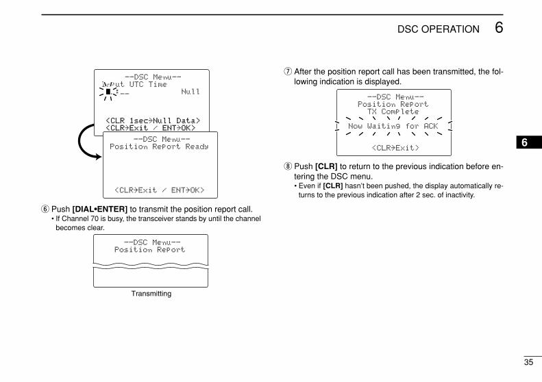
y Push [DIAL•ENTER] to transmit the position report call.• If Channel 70 is busy, the transceiver stands by until the channel
becomes clear.
u After the position report call has been transmitted, the fol-lowing indication is displayed.
i Push [CLR] to return to the previous indication before en-tering the DSC menu.• Even if [CLR] hasn’t been pushed, the display automatically re-
turns to the previous indication after 2 sec. of inactivity.
--DSC Menu--Position Report
TX Complete
Now Waiting for ACK
<CLR˘Exit>
--DSC Menu--Position Report
Transmitting
--DSC Menu--Input UTC Time__:__ Null
<CLR<CLR 1sec1sec˘NullNull Data>Data><CLR<CLR˘ExitExit / ENTENT˘OK>OK>
--DSC Menu--Position Report Ready
<CLR˘Exit / ENT˘OK>
36
6 DSC OPERATION
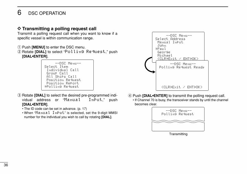
DD Transmitting a polling request callTransmit a polling request call when you want to know if aspecific vessel is within communication range.
q Push [MENU] to enter the DSC menu.w Rotate [DIAL] to select “PPoolllliinngg RReeqquueesstt,” push
[DIAL•ENTER].
e Rotate [DIAL] to select the desired pre-programmed indi-vidual address or “MMaannuuaall IInnppuutt,” push[DIAL•ENTER].• The ID code can be set in advance. (p. 17)• When “MMaannuuaall IInnppuutt” is selected, set the 9-digit MMSI
number for the individual you wish to call by rotating [DIAL].
r Push [DIAL•ENTER] to transmit the polling request call.• If Channel 70 is busy, the transceiver stands by until the channel
becomes clear.
--DSC Menu--Polling Request
Transmitting
--DSC Menu--Select AddressManual InputJohn
˘PaulGeorgeMichael<CLR˘Exit / ENT˘OK>
--DSC Menu--Polling Request Ready
<CLR˘Exit / ENT˘OK>
--DSC Menu--Select ItemIndividual CallGroup CallAll Ships CallPosition RequestPosition Report
˘Polling Request
37
6DSC OPERATION
6
t After the polling request call has been transmitted, the fol-lowing indication is displayed.
y Push [CLR] to return to the previous indication before en-tering the DSC menu.• Even if [CLR] hasn’t been pushed, the display automatically re-
turns to the previous indication after 2 sec. of inactivity.
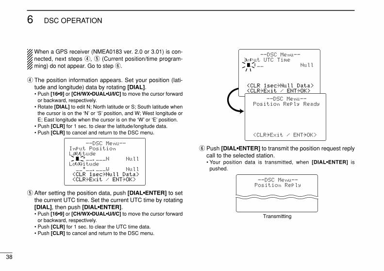
DD Transmitting a position request reply callTransmit a position request reply call when a position requestcall is received.
q Push [MENU] to enter the DSC menu.w Rotate [DIAL] to select “PPoossiittiioonn RReeppllyy,” push
[DIAL•ENTER].• “PPoossiittiioonn RReeppllyy” item appears after a position request
call is received.
e Rotate [DIAL] to select the desired individual address orID code, push [DIAL•ENTER].
--DSC Menu--Select AddressJohn
˘PaulGeorgeMichael
<CLR˘Exit / ENT˘OK>
--DSC Menu--Select ItemPosition InputIndividual CallGroup CallAll Ships CallPosition Request
˘Position Reply
--DSC Menu--Polling Request
TX Complete
Now Waiting for ACK
<CLR˘Exit>
38
6 DSC OPERATION
When a GPS receiver (NMEA0183 ver. 2.0 or 3.01) is con-nected, next steps r, t (Current position/time program-ming) do not appear. Go to step y.
r The position information appears. Set your position (lati-tude and longitude) data by rotating [DIAL].• Push [16•9] or [CH/WX•DUAL•U/I/C] to move the cursor forward
or backward, respectively.• Rotate [DIAL] to edit N; North latitude or S; South latitude when
the cursor is on the ‘N’ or ‘S’ position, and W; West longitude orE; East longitude when the cursor is on the ‘W’ or ‘E’ position.
• Push [CLR] for 1 sec. to clear the latitude/longitude data.• Push [CLR] to cancel and return to the DSC menu.
t After setting the position data, push [DIAL•ENTER] to setthe current UTC time. Set the current UTC time by rotating[DIAL], then push [DIAL•ENTER].• Push [16•9] or [CH/WX•DUAL•U/I/C] to move the cursor forward
or backward, respectively.• Push [CLR] for 1 sec. to clear the UTC time data.• Push [CLR] to cancel and return to the DSC menu.
y Push [DIAL•ENTER] to transmit the position request replycall to the selected station.• Your position data is transmitted, when [DIAL•ENTER] is
pushed.
--DSC Menu--Position Reply
Transmitting
--DSC Menu--Input UTC Time__:__ Null
<CLR<CLR 1sec1sec˘NullNull Data>Data><CLR<CLR˘ExitExit / ENTENT˘OK>OK>
--DSC Menu--Position Reply Ready
<CLR˘Exit / ENT˘OK>
--DSC Menu--Input PositionLatitude
__°__.___N NullLongitude
__°__.___W Null<CLR<CLR 1sec1sec˘NullNull Data>Data><CLR<CLR˘ExitExit / ENTENT˘OK>OK>
39
6DSC OPERATION
6
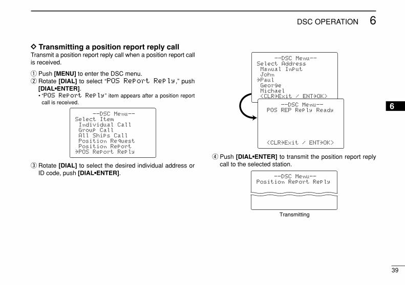
DD Transmitting a position report reply callTransmit a position report reply call when a position report callis received.
q Push [MENU] to enter the DSC menu.w Rotate [DIAL] to select “PPOOSS RReeppoorrtt RReeppllyy,” push
[DIAL•ENTER].• “PPOOSS RReeppoorrtt RReeppllyy” item appears after a position report
call is received.
e Rotate [DIAL] to select the desired individual address orID code, push [DIAL•ENTER].
r Push [DIAL•ENTER] to transmit the position report replycall to the selected station.
--DSC Menu--Position Report Reply
Transmitting
--DSC Menu--Select AddressManual InputJohn
˘PaulGeorgeMichael<CLR˘Exit / ENT˘OK>
--DSC Menu--POS REP Reply Ready
<CLR˘Exit / ENT˘OK>
--DSC Menu--Select ItemIndividual CallGroup CallAll Ships CallPosition RequestPosition Report
˘POS Report Reply
40
6 DSC OPERATION
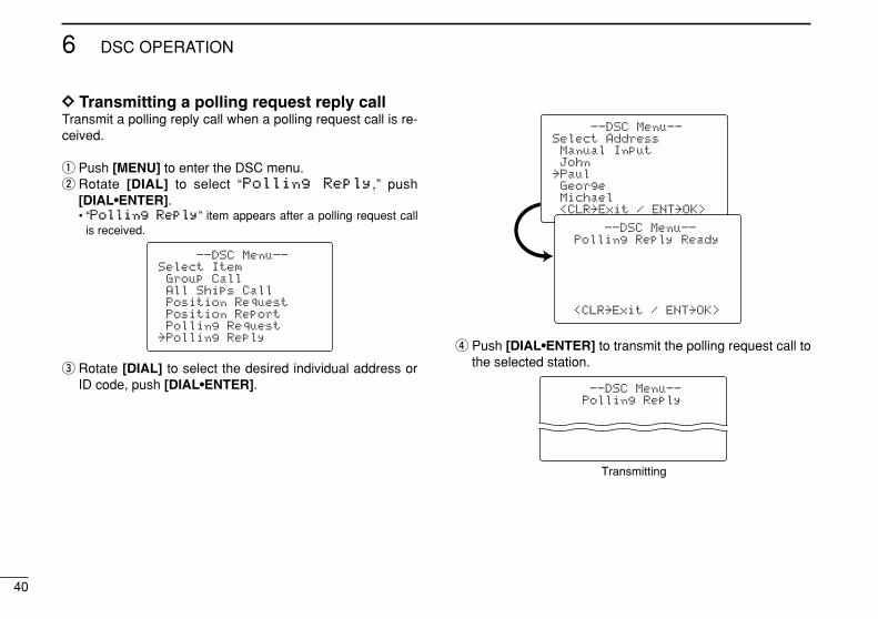
DD Transmitting a polling request reply callTransmit a polling reply call when a polling request call is re-ceived.
q Push [MENU] to enter the DSC menu.w Rotate [DIAL] to select “PPoolllliinngg RReeppllyy,” push
[DIAL•ENTER].• “PPoolllliinngg RReeppllyy” item appears after a polling request call
is received.
e Rotate [DIAL] to select the desired individual address orID code, push [DIAL•ENTER].
r Push [DIAL•ENTER] to transmit the polling request call tothe selected station.
--DSC Menu--Polling Reply
Transmitting
--DSC Menu--Select AddressManual InputJohn
˘PaulGeorgeMichael<CLR˘Exit / ENT˘OK>
--DSC Menu--Polling Reply Ready
<CLR˘Exit / ENT˘OK>
--DSC Menu--Select ItemGroup CallAll Ships CallPosition RequestPosition ReportPolling Request
˘Polling Reply
41
6DSC OPERATION
6
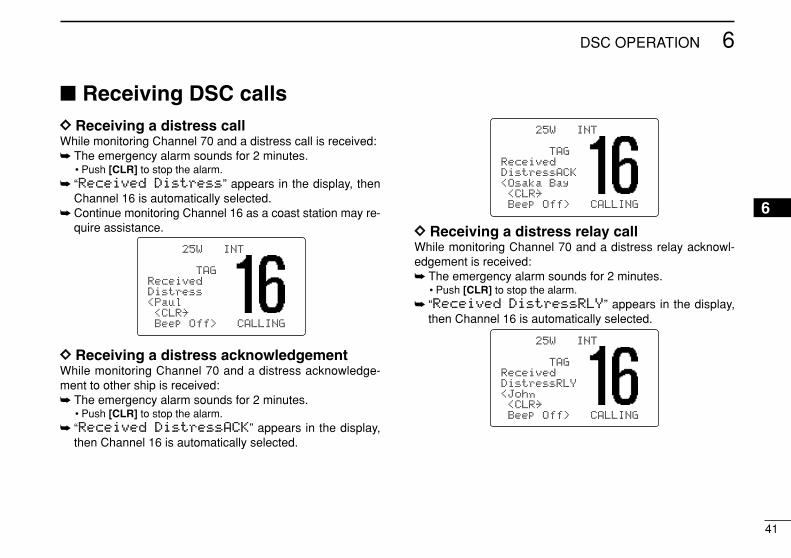
Receiving DSC callsDD Receiving a distress callWhile monitoring Channel 70 and a distress call is received: The emergency alarm sounds for 2 minutes.
• Push [CLR] to stop the alarm. “RReecceeiivveedd DDiissttrreessss” appears in the display, then
Channel 16 is automatically selected. Continue monitoring Channel 16 as a coast station may re-
quire assistance.
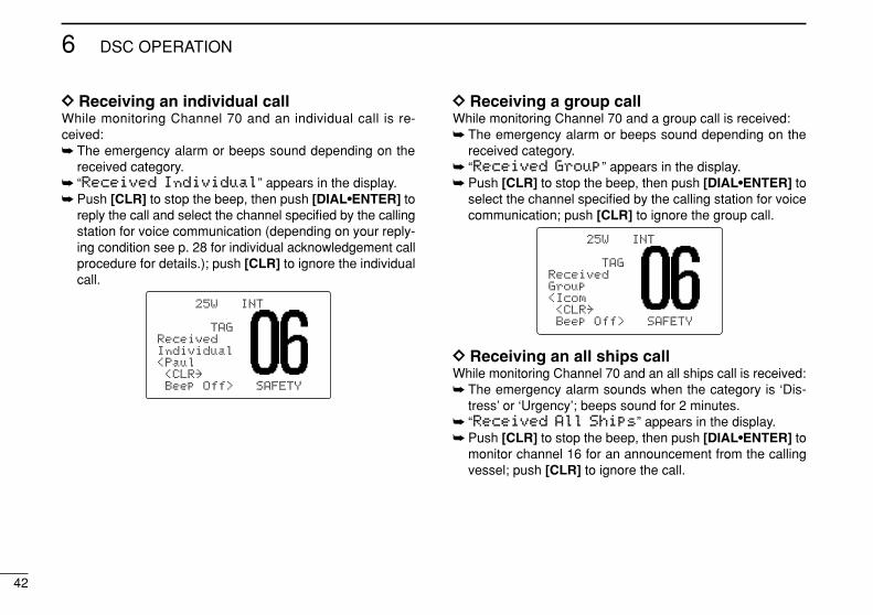
DD Receiving a distress acknowledgementWhile monitoring Channel 70 and a distress acknowledge-ment to other ship is received: The emergency alarm sounds for 2 minutes.
• Push [CLR] to stop the alarm. “RReecceeiivveedd DDiissttrreessssAACCKK” appears in the display,
then Channel 16 is automatically selected.
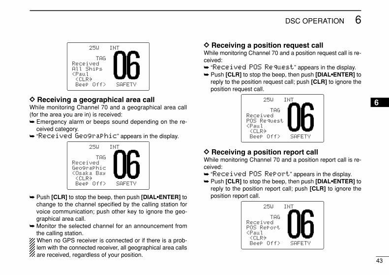
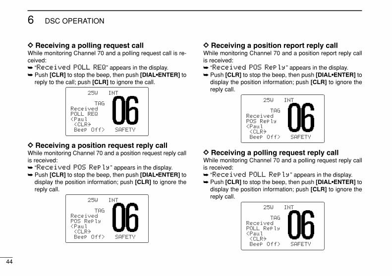
DD Receiving a distress relay callWhile monitoring Channel 70 and a distress relay acknowl-edgement is received: The emergency alarm sounds for 2 minutes.
• Push [CLR] to stop the alarm. “RReecceeiivveedd DDiissttrreessssRRLLYY” appears in the display,
then Channel 16 is automatically selected.
25W INT
TAGReceivedDistressRLY<John<CLR˘Beep Off> CALLING
25W INT
TAGReceivedDistressACK<Osaka Bay<CLR˘Beep Off> CALLING
25W INT
TAGReceivedDistress<Paul<CLR˘Beep Off> CALLING
42
6 DSC OPERATION
DD Receiving an individual callWhile monitoring Channel 70 and an individual call is re-ceived: The emergency alarm or beeps sound depending on the
received category. “RReecceeiivveedd IInnddiivviidduuaall” appears in the display. Push [CLR] to stop the beep, then push [DIAL•ENTER] to
reply the call and select the channel specified by the callingstation for voice communication (depending on your reply-ing condition see p. 28 for individual acknowledgement callprocedure for details.); push [CLR] to ignore the individualcall.
DD Receiving a group callWhile monitoring Channel 70 and a group call is received: The emergency alarm or beeps sound depending on the
received category. “RReecceeiivveedd GGrroouupp” appears in the display. Push [CLR] to stop the beep, then push [DIAL•ENTER] to
select the channel specified by the calling station for voicecommunication; push [CLR] to ignore the group call.
DD Receiving an all ships callWhile monitoring Channel 70 and an all ships call is received: The emergency alarm sounds when the category is ‘Dis-
tress’ or ‘Urgency’; beeps sound for 2 minutes. “RReecceeiivveedd AAllll SShhiippss” appears in the display. Push [CLR] to stop the beep, then push [DIAL•ENTER] to
monitor channel 16 for an announcement from the callingvessel; push [CLR] to ignore the call.
25W INT
TAGReceivedGroup<Icom<CLR˘Beep Off> SAFETY
25W INT
TAGReceivedIndividual<Paul<CLR˘Beep Off> SAFETY
43
6DSC OPERATION
6DD Receiving a geographical area callWhile monitoring Channel 70 and a geographical area call(for the area you are in) is received: Emergency alarm or beeps sound depending on the re-
ceived category. “RReecceeiivveedd GGeeooggrraapphhiicc” appears in the display.
Push [CLR] to stop the beep, then push [DIAL•ENTER] tochange to the channel specified by the calling station forvoice communication; push other key to ignore the geo-graphical area call.
Monitor the selected channel for an announcement fromthe calling station.When no GPS receiver is connected or if there is a prob-lem with the connected receiver, all geographical area callsare received, regardless of your position.
DD Receiving a position request callWhile monitoring Channel 70 and a position request call is re-ceived: “RReecceeiivveedd PPOOSS RReeqquueesstt” appears in the display. Push [CLR] to stop the beep, then push [DIAL•ENTER] to
reply to the position request call; push [CLR] to ignore theposition request call.
DD Receiving a position report callWhile monitoring Channel 70 and a position report call is re-ceived: “RReecceeiivveedd PPOOSS RReeppoorrtt” appears in the display. Push [CLR] to stop the beep, then push [DIAL•ENTER] to
reply to the position report call; push [CLR] to ignore theposition report call.
25W INT
TAGReceivedPOS Report<Paul<CLR˘Beep Off> SAFETY
25W INT
TAGReceivedPOS Request<Paul<CLR˘Beep Off> SAFETY
25W INT
TAGReceivedGeographic<Osaka Bay<CLR˘Beep Off> SAFETY
25W INT
TAGReceivedAll Ships<Paul<CLR˘Beep Off> SAFETY
44
6 DSC OPERATION
DD Receiving a polling request callWhile monitoring Channel 70 and a polling request call is re-ceived: “RReecceeiivveedd PPOOLLLL RREEQQ” appears in the display. Push [CLR] to stop the beep, then push [DIAL•ENTER] to
reply to the call; push [CLR] to ignore the call.
DD Receiving a position request reply callWhile monitoring Channel 70 and a position request reply callis received: “RReecceeiivveedd PPOOSS RReeppllyy” appears in the display. Push [CLR] to stop the beep, then push [DIAL•ENTER] to
display the position information; push [CLR] to ignore thereply call.
DD Receiving a position report reply callWhile monitoring Channel 70 and a position report reply callis received: “RReecceeiivveedd PPOOSS RReeppllyy” appears in the display. Push [CLR] to stop the beep, then push [DIAL•ENTER] to
display the position information; push [CLR] to ignore thereply call.
DD Receiving a polling request reply callWhile monitoring Channel 70 and a polling request reply callis received: “RReecceeiivveedd PPOOLLLL RReeppllyy” appears in the display. Push [CLR] to stop the beep, then push [DIAL•ENTER] to
display the position information; push [CLR] to ignore thereply call.
25W INT
TAGReceivedPOLL Reply<Paul<CLR˘Beep Off> SAFETY
25W INT
TAGReceivedPOS Reply<Paul<CLR˘Beep Off> SAFETY
25W INT
TAGReceivedPOS Reply<Paul<CLR˘Beep Off> SAFETY
25W INT
TAGReceivedPOLL REQ<Paul<CLR˘Beep Off> SAFETY
45
6DSC OPERATION
6
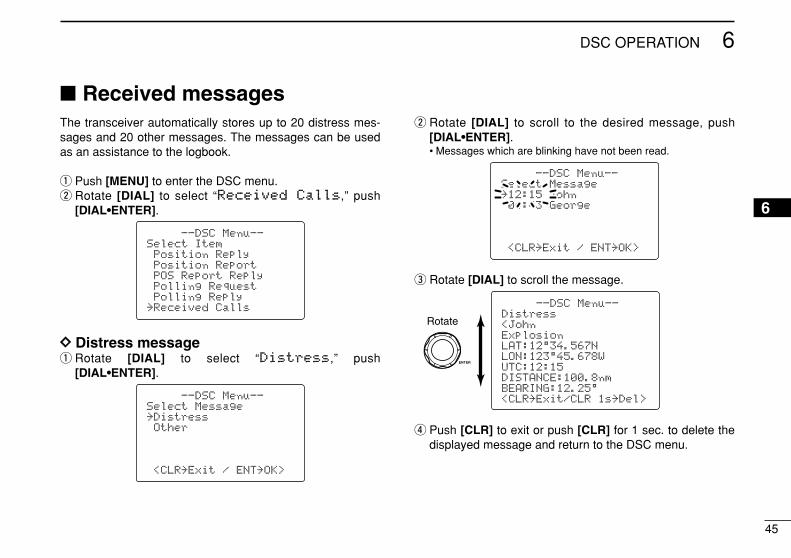
Received messagesThe transceiver automatically stores up to 20 distress mes-sages and 20 other messages. The messages can be usedas an assistance to the logbook.
q Push [MENU] to enter the DSC menu.w Rotate [DIAL] to select “RReecceeiivveedd CCaallllss,” push
[DIAL•ENTER].
DD Distress messageq Rotate [DIAL] to select “DDiissttrreessss,” push
[DIAL•ENTER].
w Rotate [DIAL] to scroll to the desired message, push[DIAL•ENTER].• Messages which are blinking have not been read.
e Rotate [DIAL] to scroll the message.
r Push [CLR] to exit or push [CLR] for 1 sec. to delete thedisplayed message and return to the DSC menu.
--DSC Menu--Distress<JohnExplosionLAT:12°34.567NLON:123°45.678WUTC:12:15DISTANCE:100.8nmBEARING:12.25°<CLR˘Exit/CLR 1s˘Del>
Rotate
--DSC Menu--Select Message˘12:15 John04:43 George
<CLR˘Exit / ENT˘OK>
--DSC Menu--Select Message˘DistressOther
<CLR˘Exit / ENT˘OK>
--DSC Menu--Select ItemPosition ReplyPosition ReportPOS Report ReplyPolling RequestPolling Reply
˘Received Calls
46
6 DSC OPERATION
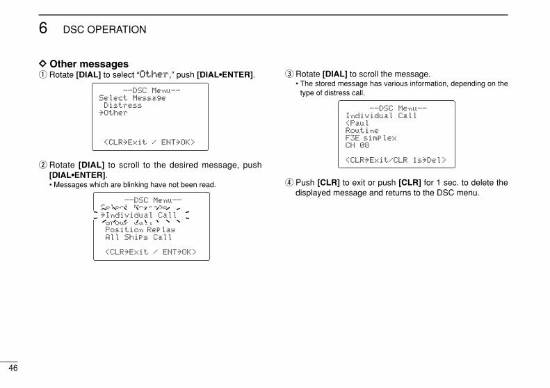
DD Other messagesq Rotate [DIAL] to select “OOtthheerr,” push [DIAL•ENTER].
w Rotate [DIAL] to scroll to the desired message, push[DIAL•ENTER].• Messages which are blinking have not been read.
e Rotate [DIAL] to scroll the message.• The stored message has various information, depending on the
type of distress call.
r Push [CLR] to exit or push [CLR] for 1 sec. to delete thedisplayed message and returns to the DSC menu.
--DSC Menu--Individual Call<PaulRoutineF3E simplexCH 08
<CLR˘Exit/CLR 1s˘Del>
--DSC Menu--Select Message˘Individual CallGroup CallPosition ReplayAll Ships Call
<CLR˘Exit / ENT˘OK>
˘Individual Call
--DSC Menu--Select MessageDistress
˘Other
<CLR˘Exit / ENT˘OK>
47
6DSC OPERATION
6
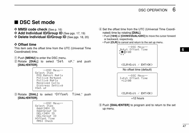
DSC Set modeDD MMSI code check (See p. 16)DD Add Individual ID/Group ID (See pgs. 17, 19)DD Delete Individual ID/Group ID (See pgs. 18, 20)
DD Offset timeThis item sets the offset time from the UTC (Universal TimeCoordinated) time.
q Push [MENU] to enter the DSC menu.w Rotate [DIAL] to select “SSeett uupp,” and push
[DIAL•ENTER].
e Rotate [DIAL] to select “OOffffsseett TTiimmee,” push[DIAL•ENTER].
r Set the offset time from the UTC (Universal Time Coordi-nated) time by rotating [DIAL].• Push [16•9] or [CH/WX•DUAL•U/I/C] to move the cursor forward
or backward, respectively.• Push [CLR] to cancel and return to the set up menu.
t Push [DIAL•ENTER] to program and to return to the setup menu.
--DSC Menu--Input Offset Time+12:00
<CLR<CLR˘ExitExit / ENTENT˘OK>OK>
--DSC Menu--Input Offset Time
00:00
<CLR<CLR˘ExitExit / ENTENT˘OK>OK>
No offset time (default)
+12 hours
--DSC Menu--Select ItemAdd:INDV IDAdd:Group IDDEL:INDV IDDEL:Group ID
˘Offset TimeMMSI Check
--DSC Menu--Select ItemPOS Report ReplyPolling RequestPolling ReplyReceived CallsDistress Setting
˘Set up
48
6 DSC OPERATION
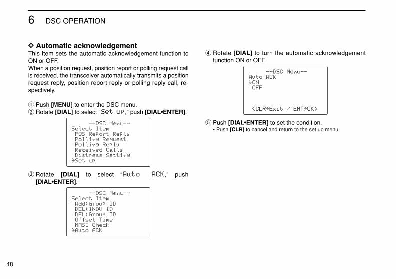
DD Automatic acknowledgement This item sets the automatic acknowledgement function toON or OFF.When a position request, position report or polling request callis received, the transceiver automatically transmits a positionrequest reply, position report reply or polling reply call, re-spectively.
q Push [MENU] to enter the DSC menu.w Rotate [DIAL] to select “SSeett uupp,” push [DIAL•ENTER].
e Rotate [DIAL] to select “AAuuttoo AACCKK,” push [DIAL•ENTER].
r Rotate [DIAL] to turn the automatic acknowledgementfunction ON or OFF.
t Push [DIAL•ENTER] to set the condition.• Push [CLR] to cancel and return to the set up menu.
--DSC Menu--Auto ACK˘ONOFF
<CLR<CLR˘ExitExit / ENTENT˘OK>OK>
--DSC Menu--Select ItemAdd:Group IDDEL:INDV IDDEL:Group IDOffset TimeMMSI Check
˘Auto ACK
--DSC Menu--Select ItemPOS Report ReplyPolling RequestPolling ReplyReceived CallsDistress Setting
˘Set up
49
6DSC OPERATION
6
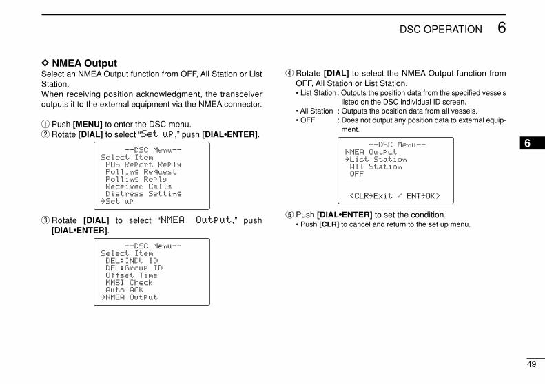
DD NMEA OutputSelect an NMEA Output function from OFF, All Station or ListStation.When receiving position acknowledgment, the transceiveroutputs it to the external equipment via the NMEA connector.
q Push [MENU] to enter the DSC menu.w Rotate [DIAL] to select “SSeett uupp,” push [DIAL•ENTER].
e Rotate [DIAL] to select “NNMMEEAA OOuuttppuutt,” push [DIAL•ENTER].
r Rotate [DIAL] to select the NMEA Output function fromOFF, All Station or List Station.• List Station: Outputs the position data from the specified vessels
listed on the DSC individual ID screen.• All Station : Outputs the position data from all vessels.• OFF : Does not output any position data to external equip-
ment.
t Push [DIAL•ENTER] to set the condition.• Push [CLR] to cancel and return to the set up menu.
--DSC Menu--NMEA Output˘List StationAll StationOFF
<CLR<CLR˘ExitExit / ENTENT˘OK>OK>
--DSC Menu--Select ItemDEL:INDV IDDEL:Group IDOffset TimeMMSI CheckAuto ACK
˘NMEA Output
--DSC Menu--Select ItemPOS Report ReplyPolling RequestPolling ReplyReceived CallsDistress Setting
˘Set up
50
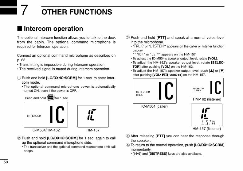
OTHER FUNCTIONS7 Intercom operationThe optional Intercom function allows you to talk to the deckfrom the cabin. The optional command microphone isrequired for Intercom operation.
Connect an optional command microphone as described onp. 63.• Transmitting is impossible during Intercom operation.• The received signal is muted during Intercom operation.
q Push and hold [LO/DX•IC•SCRM] for 1 sec. to enter Inter-com mode.• The optional command microphone power is automatically
turned ON, even if the power is OFF.
w Push and hold [LO/DX•IC•SCRM] for 1 sec. again to callup the optional command microphone side.• The transceiver and the optional command microphone emit call
beeps.
e Push and hold [PTT] and speak at a normal voice levelinto the microphone.• “TTAALLKK” or “LLIISSTTEENN”* appears on the caller or listener function
display.* “ ” or “ ” appears on the HM-157.
• To adjust the IC-M504’s speaker output level, rotate [VOL].• To adjust the HM-162’s speaker output level, rotate [SELEC-
TOR] after pushing [VOL] on the HM-162.• To adjust the HM-157’s speaker output level, push [Y] or [Z]
after pushing [VOL• PA/RX ] on the HM-157.
r After releasing [PTT] you can hear the response throughthe speaker.
t To return to the normal operation, push [LO/DX•IC•SCRM]momentarily.• [16•9] and [DISTRESS] keys are also available.
INTERCOMINTERCOMTALKTALK
IC-M504 (caller)
HM-157 (listener)
INTERCOMINTERCOMLISTENLISTEN
HM-162 (listener)
DIM
INTERCOMINTERCOM
IC-M504/HM-162 HM-157
Push and hold for 1 sec.
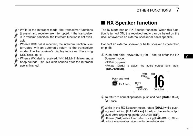
51
7OTHER FUNCTIONS
7
• While in the Intercom mode, the transceiver functions(transmit and receive) are interrupted. If the transceiveris in transmit condition, the Intercom function is not avail-able.
• When a DSC call is received, the intercom function is in-terrupted with an automatic return to the transceivermode. The transceiver’s display indicates ‘ReceivingDSC calls.’ (p. 41)
• When a WX alert is received, “WWXX AALLEERRTT” blinks and abeep sounds. The WX alert sounds after the Intercomuse is finished.
RX Speaker functionThe IC-M504 has an RX Speaker function. When this func-tion is turned ON, the received audio can be heard on thedeck or tower via an external speaker or hailer speaker.
Connect an external speaker or hailer speaker as describedon p. 58.
q Push and hold [HAIL•RX ] for 1 sec. to enter the RXSpeaker mode.• “RRXX ” appears• Rotate [DIAL] to adjust the audio output level, push
[DIAL•ENTER].
w To return to normal operation, push and hold [HAIL•RX ]for 1 sec.
While in the RX Speaker mode, rotate [DIAL] while push-ing and holding [HAIL•RX ] to adjust the audio outputlevel. After adjusting, push [DIAL•ENTER].• Rotate [DIAL] within 1 sec. after pushing [HAIL•RX ]. Other-
wise the transceiver returns to the normal operation.
25W25W INTINTRXRX
TAGTAG
RXRX1515
<ENT<ENT˘OK>OK> CALLINGCALLING
Push and hold
for 1 sec.
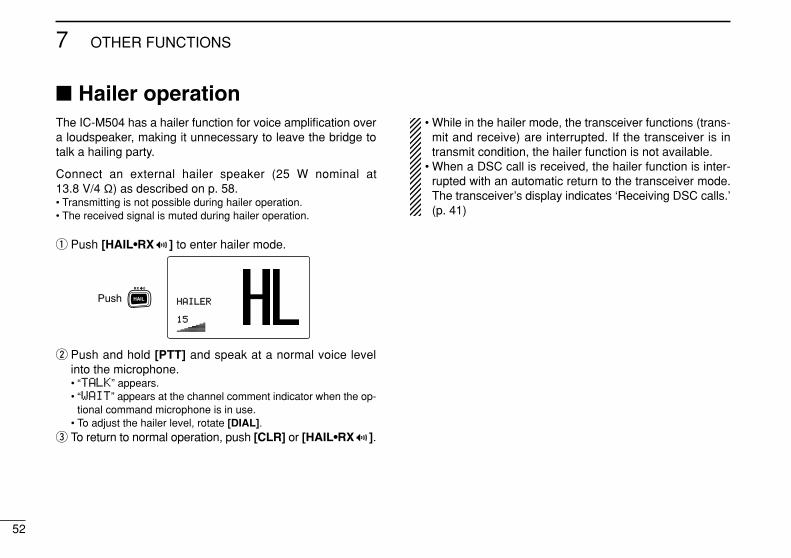
52
7 OTHER FUNCTIONS
Hailer operationThe IC-M504 has a hailer function for voice amplification overa loudspeaker, making it unnecessary to leave the bridge totalk a hailing party.
Connect an external hailer speaker (25 W nominal at13.8 V/4 Ω) as described on p. 58.• Transmitting is not possible during hailer operation.• The received signal is muted during hailer operation.
q Push [HAIL•RX ] to enter hailer mode.
w Push and hold [PTT] and speak at a normal voice levelinto the microphone.• “TTAALLKK” appears.• “WWAAIITT” appears at the channel comment indicator when the op-
tional command microphone is in use.• To adjust the hailer level, rotate [DIAL].
e To return to normal operation, push [CLR] or [HAIL•RX ].
• While in the hailer mode, the transceiver functions (trans-mit and receive) are interrupted. If the transceiver is intransmit condition, the hailer function is not available.
• When a DSC call is received, the hailer function is inter-rupted with an automatic return to the transceiver mode.The transceiver’s display indicates ‘Receiving DSC calls.’(p. 41)
HAILERHAILER
1515
Push
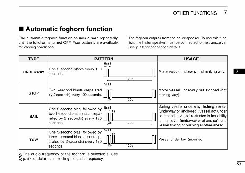
53
7OTHER FUNCTIONS
7
Automatic foghorn functionThe automatic foghorn function sounds a horn repeatedlyuntil the function is turned OFF. Four patterns are availablefor varying conditions.
The foghorn outputs from the hailer speaker. To use this func-tion, the hailer speaker must be connected to the transceiver.See p. 58 for connection details.
TYPE PATTERN USAGE
UNDERWAY
STOP
SAIL
TOW
The audio frequency of the foghorn is selectable. Seep. 57 for details on selecting the audio frequency.
One 5-second blasts every 120seconds.
Two 5-second blasts (separatedby 2 seconds) every 120 seconds.
One 5-second blast followed bytwo 1-second blasts (each sepa-rated by 2 seconds) every 120seconds.
One 5-second blast followed bythree 1-second blasts (each sep-arated by 2-seconds) every 120seconds.
Motor vessel underway and making way.
Motor vessel underway but stopped (notmaking way).
Sailing vessel underway, fishing vessel(underway or anchored), vessel not undercommand, a vessel restricted in her abilityto maneuver (underway or at anchor), or avessel towing or pushing another ahead.
Vessel under tow (manned).
5s±1
120s
5s±1
2s
1s
120s
5s±1
2s
1s
120s
5s±1
2s 120s
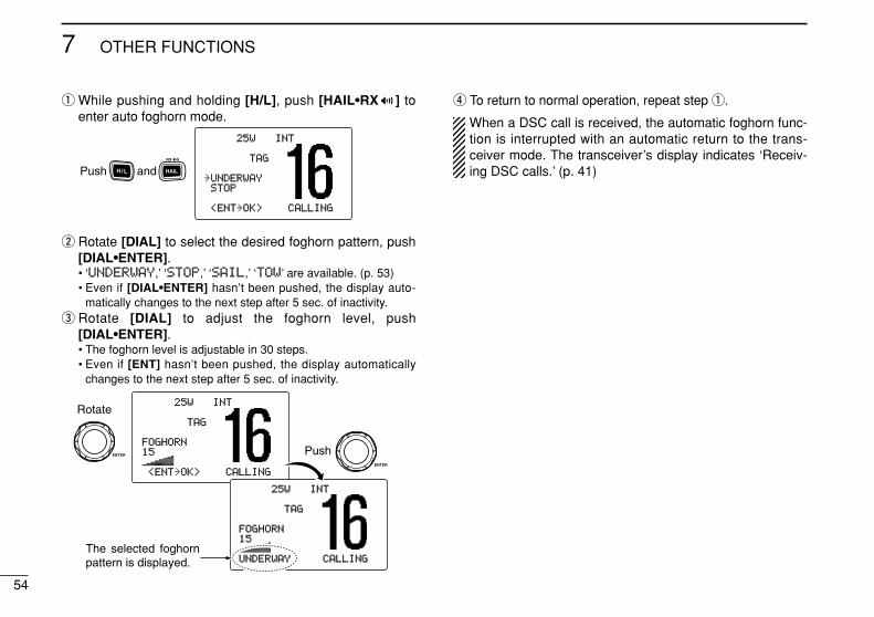
54
7 OTHER FUNCTIONS
q While pushing and holding [H/L], push [HAIL•RX ] toenter auto foghorn mode.
w Rotate [DIAL] to select the desired foghorn pattern, push[DIAL•ENTER].• ‘UUNNDDEERRWWAAYY,’ ‘SSTTOOPP,’ ‘SSAAIILL,’ ‘TTOOWW’ are available. (p. 53)• Even if [DIAL•ENTER] hasn’t been pushed, the display auto-
matically changes to the next step after 5 sec. of inactivity.e Rotate [DIAL] to adjust the foghorn level, push
[DIAL•ENTER].• The foghorn level is adjustable in 30 steps.• Even if [ENT] hasn’t been pushed, the display automatically
changes to the next step after 5 sec. of inactivity.
r To return to normal operation, repeat step q.
When a DSC call is received, the automatic foghorn func-tion is interrupted with an automatic return to the trans-ceiver mode. The transceiver’s display indicates ‘Receiv-ing DSC calls.’ (p. 41)
25W25W INTINT
TAGTAG
FOGHORNFOGHORN1515
<ENT<ENT˘OK>OK> CALLINGCALLING
Rotate
Push
25W25W INTINT
TAGTAG
FOGHORNFOGHORN1515
UNDERWAYUNDERWAY CALLINGCALLINGThe selected foghorn pattern is displayed.
25W25W INTINT
TAGTAG
˘UNDERWAYUNDERWAYSTOPSTOP
<ENT<ENT˘OK>OK> CALLINGCALLING
Push and
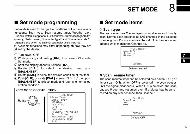
55
8SET MODE
78
Set mode programmingSet mode is used to change the conditions of the transceiver’sfunctions: Scan type, Scan resume timer, Weather alert,Dual/Tri-watch, Beep tone, LCD contrast, Automatic foghorn fre-quency, Radio power, Scrambler type* and Scrambler code.**Appears only when the optional scrambler unit is installed.
Available functions may differ depending on how they areset by the dealer.
q Turn power OFF.w While pushing and holding [16•9], turn power ON to enter
Set mode.e After the display appears, release [16•9].r Rotate [DIAL] to select the desired item, push
[DIAL•ENTER].t Rotate [DIAL] to select the desired condition of the item.y Push [CLR], or rotate [DIAL] to select “EExxiitt,” then push
[DIAL•ENTER] to exit set mode and returns to normal op-eration condition.
Set mode itemsD Scan typeThe transceiver has 2 scan types: Normal scan and Priorityscan. Normal scan searches all TAG channels in the selectedchannel group. Priority scan searches all TAG channels in se-quence while monitoring Channel 16.
DD Scan resume timerThe scan resume timer can be selected as a pause (OFF) ortimer scan (ON). When OFF is selected, the scan pausesuntil the signal disappears. When ON is selected, the scanpauses 5 sec. and resumes even if a signal has been re-ceived on any other channel than Channel 16.
--Set Mode--Scan TimerON
˘OFF
<ENT˘OK>
Default: OFF
--Set Mode--Scan TypePriority
˘Normal
<ENT˘OK>
Default: Normal
Rotate
--Set Mode--˘Scan TypeScan TimerWX AlertDual/TriBeepContrastFoghorn FrequencyRadio PowerScrambler TypeScrambler CodeExit
• SET MODE CONSTRUCTION
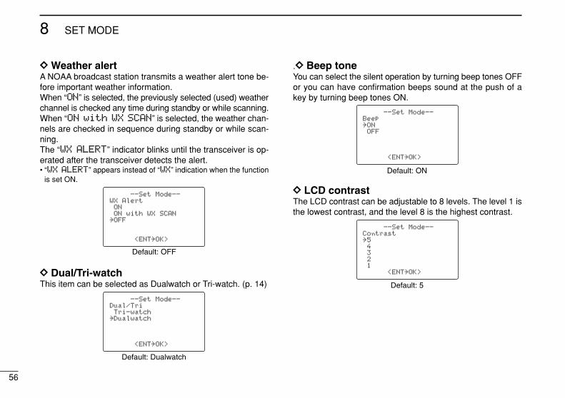
56
8 SET MODE
DD Weather alertA NOAA broadcast station transmits a weather alert tone be-fore important weather information. When “OONN” is selected, the previously selected (used) weatherchannel is checked any time during standby or while scanning.When “OONN wwiitthh WWXX SSCCAANN” is selected, the weather chan-nels are checked in sequence during standby or while scan-ning.The “WWXX AALLEERRTT” indicator blinks until the transceiver is op-erated after the transceiver detects the alert.• “WWXX AALLEERRTT” appears instead of “WWXX” indication when the function
is set ON.
DD Dual/Tri-watchThis item can be selected as Dualwatch or Tri-watch. (p. 14)
.DD Beep toneYou can select the silent operation by turning beep tones OFFor you can have confirmation beeps sound at the push of akey by turning beep tones ON.
DD LCD contrastThe LCD contrast can be adjustable to 8 levels. The level 1 isthe lowest contrast, and the level 8 is the highest contrast.
--Set Mode--Contrast˘54321
<ENT˘OK>
Default: 5
--Set Mode--Beep˘ONOFF
<ENT˘OK>
Default: ON
--Set Mode--Dual/TriTri-watch
˘Dualwatch
<ENT˘OK>
Default: Dualwatch
--Set Mode--WX AlertONON with WX SCAN
˘OFF
<ENT˘OK>
Default: OFF
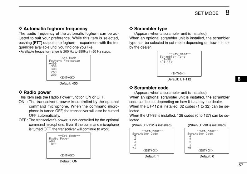
57
8SET MODE
8
DD Automatic foghorn frequencyThe audio frequency of the automatic foghorn can be ad-justed to suit your preference. While this item is selected,pushing [PTT] outputs the foghorn— experiment with the fre-quencies available until you find one you like.• Available frequency range is 200 Hz to 850Hz in 50 Hz steps.
DD Radio powerThis item sets the Radio Power function ON or OFF.ON : The transceiver’s power is controlled by the optional
command microphone. When the command micro-phone is turned OFF, the transceiver will also be turnedOFF automatically.
OFF : The transceiver’s power is not controlled by the optionalcommand microphone. Even if the command microphoneis turned OFF, the transceiver will continue to work.
DD Scrambler type (Appears when a scrambler unit is installed)
When an optional scrambler unit is installed, the scramblertype can be selected in set mode depending on how it is setby the dealer.
DD Scrambler code (Appears when a scrambler unit is installed)
When an optional scrambler unit is installed, the scramblercode can be set depending on how it is set by the dealer.When the UT-112 is installed, 32 codes (1 to 32) can be se-lected.When the UT-98 is installed, 128 codes (0 to 127) can be se-lected.
--Set Mode--Scrambler Code5432
˘1<ENT˘OK>
--Set Mode--Scrambler Code4321
˘0<ENT˘OK>
Default: 0
(When UT-98 is installed)
Default: 1
(When UT-112 is installed)
--Set Mode--Scrambler TypeUT-98
˘UT-112
<ENT˘OK>
Default: UT-112
--Set Mode--Radio Power˘ONOFF
<ENT˘OK>
Default: ON
--Set Mode--Foghorn Frequency˘400350300250200
<ENT˘OK>
Default: 400
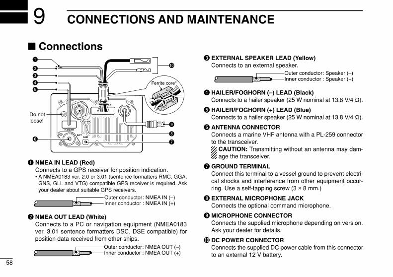
58
CONNECTIONS AND MAINTENANCE9 Connections
q NMEA IN LEAD (Red)Connects to a GPS receiver for position indication.• A NMEA0183 ver. 2.0 or 3.01 (sentence formatters RMC, GGA,
GNS, GLL and VTG) compatible GPS receiver is required. Askyour dealer about suitable GPS receivers.
w NMEA OUT LEAD (White)Connects to a PC or navigation equipment (NMEA0183ver. 3.01 sentence formatters DSC, DSE compatible) forposition data received from other ships.
e EXTERNAL SPEAKER LEAD (Yellow)Connects to an external speaker.
r HAILER/FOGHORN (–) LEAD (Black)Connects to a hailer speaker (25 W nominal at 13.8 V/4 Ω).
t HAILER/FOGHORN (+) LEAD (Blue)Connects to a hailer speaker (25 W nominal at 13.8 V/4 Ω).
y ANTENNA CONNECTORConnects a marine VHF antenna with a PL-259 connectorto the transceiver.
CAUTION: Transmitting without an antenna may dam-age the transceiver.
u GROUND TERMINALConnect this terminal to a vessel ground to prevent electri-cal shocks and interference from other equipment occur-ring. Use a self-tapping screw (3 × 8 mm.)
i EXTERNAL MICROPHONE JACKConnects the optional command microphone.
o MICROPHONE CONNECTORConnects the supplied microphone depending on version.Ask your dealer for details.
!0 DC POWER CONNECTORConnects the supplied DC power cable from this connectorto an external 12 V battery.
Do not loose!
!0
r
t
y
w
q
e
u
Ferrite core*
i
o
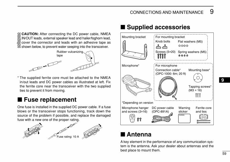
59
9CONNECTIONS AND MAINTENANCE
9
CAUTION: After connecting the DC power cable, NMEAIN/OUT leads, external speaker lead and hailer/foghorn lead,cover the connector and leads with an adhesive tape asshown below, to prevent water seeping into the transceiver.
* The supplied ferrite core must be attached to the NMEAin/out leads and DC power cables as illustrated at left. Fixthe ferrite core near the transceiver with the two suppliedties to prevent it from moving.
Fuse replacementOne fuse is installed in the supplied DC power cable. If a fuseblows or the transceiver stops functioning, track down thesource of the problem if possible, and replace the damagedfuse with a new one of the proper rating.
Supplied accessories
AntennaA key element in the performance of any communication sys-tem is the antenna. Ask your dealer about antennas and thebest place to mount them.
Connection cable* (OPC-1000: 6m; 20 ft)
Mounting bracket For mounting bracket
DC power cable (OPC-891A)
Microphone hanger and screws (3×16)
Knob bolts
Screws (5×20)
Flat washers (M5)
Spring washers (M5)
Warningsticker
Ferrite coreand ties
Mounting base*
Tapping screws*(M3 × 16)
For microphoneMicrophone*
*Depending on version
Fuse rating: 10 A
Rubber vulcanizingtape
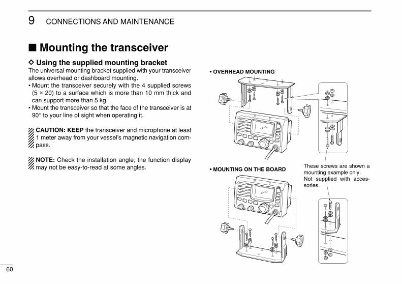
60
9 CONNECTIONS AND MAINTENANCE
Mounting the transceiverDD Using the supplied mounting bracketThe universal mounting bracket supplied with your transceiverallows overhead or dashboard mounting.• Mount the transceiver securely with the 4 supplied screws
(5 × 20) to a surface which is more than 10 mm thick andcan support more than 5 kg.
• Mount the transceiver so that the face of the transceiver is at90° to your line of sight when operating it.
CAUTION: KEEP the transceiver and microphone at least1 meter away from your vessel’s magnetic navigation com-pass.
NOTE: Check the installation angle; the function displaymay not be easy-to-read at some angles.
• OVERHEAD MOUNTING
• MOUNTING ON THE BOARDThese screws are shown a mounting example only. Not supplied with acces-sories.
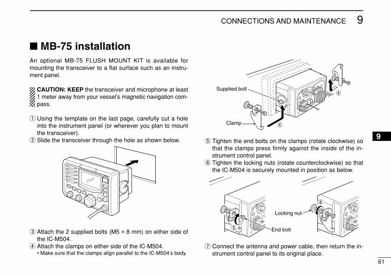
61
9CONNECTIONS AND MAINTENANCE
9
MB-75 installationAn optional MB-75 FLUSH MOUNT KIT is available formounting the transceiver to a flat surface such as an instru-ment panel.
CAUTION: KEEP the transceiver and microphone at least1 meter away from your vessel’s magnetic navigation com-pass.
q Using the template on the last page, carefully cut a holeinto the instrument panel (or wherever you plan to mountthe transceiver).
w Slide the transceiver through the hole as shown below.
e Attach the 2 supplied bolts (M5 × 8 mm) on either side ofthe IC-M504.
r Attach the clamps on either side of the IC-M504.• Make sure that the clamps align parallel to the IC-M504’s body.
t Tighten the end bolts on the clamps (rotate clockwise) sothat the clamps press firmly against the inside of the in-strument control panel.
y Tighten the locking nuts (rotate counterclockwise) so thatthe IC-M504 is securely mounted in position as below.
u Connect the antenna and power cable, then return the in-strument control panel to its original place.
t
y
End bolt
Locking nut
r
r
Clamp
Supplied bolt
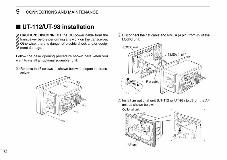
62
9 CONNECTIONS AND MAINTENANCE
UT-112/UT-98 installationCAUTION: DISCONNECT the DC power cable from thetransceiver before performing any work on the transceiver.Otherwise, there is danger of electric shock and/or equip-ment damage.
Follow the case opening procedure shown here when youwant to install an optional scrambler unit.
q Remove the 6 screws as shown below and open the trans-ceiver.
w Disconnect the flat cable and NMEA (4 pin) from J5 of theLOGIC unit.
e Install an optional unit (UT-112 or UT-98) to J3 on the AFunit as shown below.Optional unit
AF unit
J3
q
LOGIC unit
NMEA (4 pin)
Flat cablew
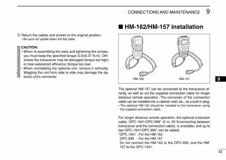
63
9CONNECTIONS AND MAINTENANCE
9
r Return the cables and screws to the original position.• Be sure not upside down the flat cable.
CAUTION:• When re-assembling the case and tightening the screws,
you must keep the specified torque (0.5±0.07 N.m). Oth-erwise the transceiver may be damaged (torque too high)or lose waterproof efficiency (torque too low).
• When uninstalling the optional unit, remove it vertically.Wiggling the unit from side to side may damage the op-tional unit's connector.
HM-162/HM-157 installation
The optional HM-157 can be connected to the transceiver di-rectly, as well as via the supplied connection cable for longerdistance remote operation. The connector of the connectioncable can be installed into a cabinet, wall, etc., as a built-in plug.• The optional HM-162 should be installed to the transceiver using
the supplied connection cable.
For longer distance remote operation, the optional extensioncable, OPC-1541/OPC-999* (6 m; 20 ft/connecting betweentransceiver and the connection cable), is available, and up totwo OPC-1541/OPC-999* can be added.*OPC-1541 : For the HM-162OPC-999 : For the HM-157Do not connect the HM-162 to the OPC-999, and the HM-157 to the OPC-1541.
HM-157HM-162
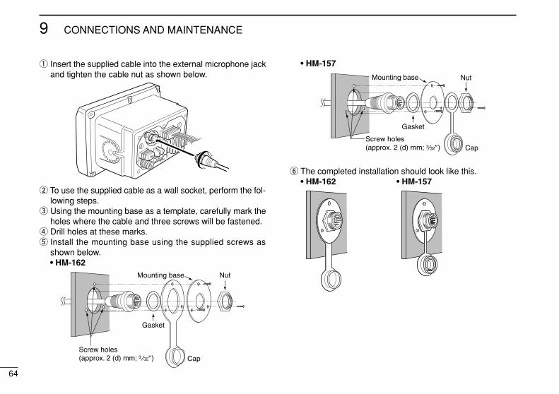
64
9 CONNECTIONS AND MAINTENANCE
q Insert the supplied cable into the external microphone jackand tighten the cable nut as shown below.
w To use the supplied cable as a wall socket, perform the fol-lowing steps.
e Using the mounting base as a template, carefully mark theholes where the cable and three screws will be fastened.
r Drill holes at these marks.t Install the mounting base using the supplied screws as
shown below.• HM-162
• HM-157
y The completed installation should look like this.• HM-162 • HM-157
Gasket
Cap
Mounting base Nut
Screw holes(approx. 2 (d) mm; 3 32″)
Gasket
Cap
Mounting base Nut
Screw holes(approx. 2 (d) mm; 3 32″)
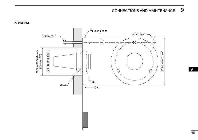
65
9CONNECTIONS AND MAINTENANCE
9
Gasket
Mounting base
Cap
Nut
DD HM-162

66
9 CONNECTIONS AND MAINTENANCE
50 (
d) m
m; 1
31⁄32
˝
23 (
d) m
m; 29
⁄32˝
24 to
27
(d)
mm
(15
⁄16 to
11 ⁄1
6˝)
5 mm; 3⁄16˝
Gasket
Mounting base
Cap
Nut
2 mm; 3⁄32˝
DD HM-157
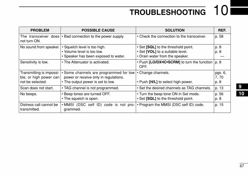
67
10TROUBLESHOOTING
910
PROBLEM POSSIBLE CAUSE SOLUTION REF.
No sound from speaker. • Squelch level is too high.• Volume level is too low.• Speaker has been exposed to water.
p. 8p. 8
—
• Set [SQL] to the threshold point.• Set [VOL] to a suitable level.• Drain water from the speaker.
The transceiver doesnot turn ON.
• Bad connection to the power supply. p. 58• Check the connection to the transceiver.
Transmitting is impossi-ble, or high power cannot be selected.
• Some channels are programmed for lowpower or receive only in regulations.
• The output power is set to low.
pgs. 6,7, 70p. 8
• Change channels.
• Push [H/L] to select high power.
Scan does not start. • TAG channel is not programmed. • Set the desired channels as TAG channels. p. 13
No beeps. • Beep tones are turned OFF.• The squelch is open.
• Turn the beep tone ON in Set mode.• Set [SQL] to the threshold point.
p. 56p. 8
Distress call cannot betransmitted.
• MMSI (DSC self ID) code is not pro-grammed.
• Program the MMSI (DSC self ID) code. p. 15
Sensitivity is low. • The Attenuator is activated. • Push [LO/DX•IC•SCRM] to turn the functionOFF.
p. 8
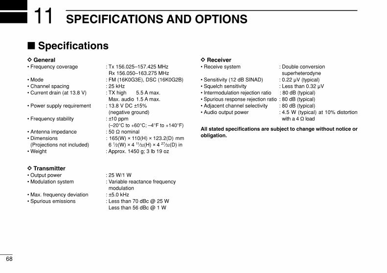
68
SPECIFICATIONS AND OPTIONS11 SpecificationsDD General• Frequency coverage : Tx 156.025–157.425 MHz
Rx 156.050–163.275 MHz• Mode : FM (16K0G3E), DSC (16K0G2B)• Channel spacing : 25 kHz• Current drain (at 13.8 V) : TX high 5.5 A max.
Max. audio 1.5 A max.• Power supply requirement : 13.8 V DC ±15%
(negative ground)• Frequency stability : ±10 ppm
(–20°C to +60°C; –4°F to +140°F)• Antenna impedance : 50 Ω nominal• Dimensions : 165(W) × 110(H) × 123.2(D) mm
(Projections not included) 6 1⁄2(W) × 4 11⁄32(H) × 4 27⁄32(D) in• Weight : Approx. 1450 g; 3 lb 19 oz
DD Transmitter• Output power : 25 W/1 W• Modulation system : Variable reactance frequency
modulation• Max. frequency deviation : ±5.0 kHz• Spurious emissions : Less than 70 dBc @ 25 W
Less than 56 dBc @ 1 W
DD Receiver• Receive system : Double conversion
superheterodyne• Sensitivity (12 dB SINAD) : 0.22 µV (typical)• Squelch sensitivity : Less than 0.32 µV• Intermodulation rejection ratio : 80 dB (typical)• Spurious response rejection ratio : 80 dB (typical)• Adjacent channel selectivity : 80 dB (typical)• Audio output power : 4.5 W (typical) at 10% distortion
with a 4 Ω load
All stated specifications are subject to change without notice orobligation.
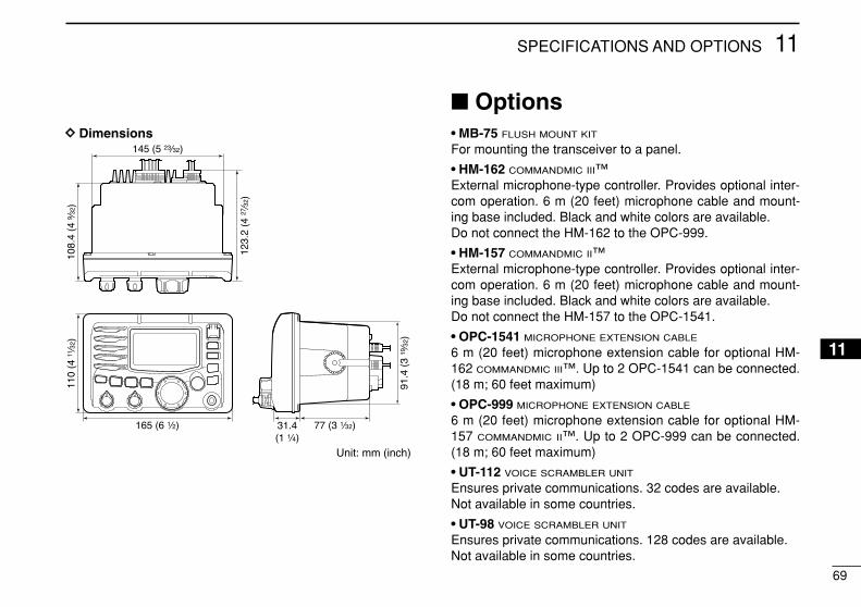
69
11SPECIFICATIONS AND OPTIONS
11
DD Dimensions
Options• MB-75 FLUSH MOUNT KIT
For mounting the transceiver to a panel.
• HM-162 COMMANDMIC III™External microphone-type controller. Provides optional inter-com operation. 6 m (20 feet) microphone cable and mount-ing base included. Black and white colors are available.Do not connect the HM-162 to the OPC-999.
• HM-157 COMMANDMIC II™External microphone-type controller. Provides optional inter-com operation. 6 m (20 feet) microphone cable and mount-ing base included. Black and white colors are available.Do not connect the HM-157 to the OPC-1541.
• OPC-1541 MICROPHONE EXTENSION CABLE
6 m (20 feet) microphone extension cable for optional HM-162 COMMANDMIC III™. Up to 2 OPC-1541 can be connected.(18 m; 60 feet maximum)
• OPC-999 MICROPHONE EXTENSION CABLE
6 m (20 feet) microphone extension cable for optional HM-157 COMMANDMIC II™. Up to 2 OPC-999 can be connected.(18 m; 60 feet maximum)
• UT-112 VOICE SCRAMBLER UNIT
Ensures private communications. 32 codes are available.Not available in some countries.
• UT-98 VOICE SCRAMBLER UNIT
Ensures private communications. 128 codes are available.Not available in some countries.
Unit: mm (inch)
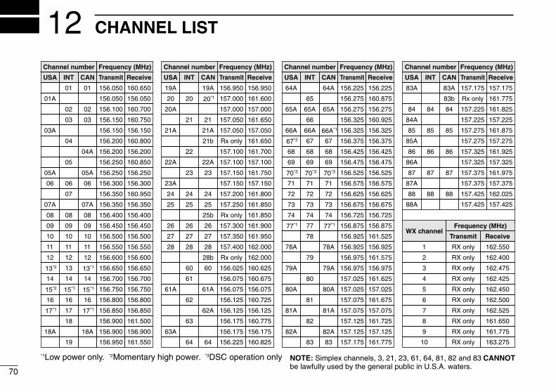
70
CHANNEL LIST12Channel number
USA CAN Transmit Receive
01 156.050 160.650
01A 156.050 156.050
02 156.100 160.700
03 156.150 160.750
03A 156.150 156.150
156.200 160.800
04A 156.200 156.200
156.250 160.850
05A 05A 156.250 156.250
06 06 156.300 156.300
156.350 160.950
07A 07A 156.350 156.350
08 08 156.400 156.400
09 09 156.450 156.450
10 10 156.500 156.500
11 11 156.550 156.550
12 12 156.600 156.600
13*2 13*1 156.650 156.650
14 14 156.700 156.700
15*2 15*1 156.750 156.750
16 16 156.800 156.800
17*1 17*1 156.850 156.850
156.900 161.500
18A 18A 156.900 156.900
Frequency (MHz)
INT
01
02
03
04
05
06
07
08
09
10
11
12
13
14
15*1
16
17
18
Channel number Frequency (MHz)
USA CAN Transmit Receive
19A 19A 156.950 156.950
20 20*1 157.000 161.600
21 157.050 161.650
21A 21A 157.050 157.050
157.100 161.700
22A 22A 157.100 157.100
23 157.150 161.750
23A 157.150 157.150
24 24 157.200 161.800
25 25 157.250 161.850
26 26 157.300 161.900
27 27 157.350 161.950
28 28 157.400 162.000
60 156.025 160.625
156.075 160.675
61A 61A 156.075 156.075
156.125 160.725
62A 156.125 156.125
156.175 160.775
63A 156.175 156.175
64 156.225 160.825
INT
20
21
22
23
24
25
26
27
28
60
61
62
63
64
20A 157.000 157.000
Channel number
66A
Frequency (MHz)
66A*1
USA CAN Transmit Receive
64A 64A 156.225 156.225
65A 65A 156.275 156.275
156.325 160.925
67*2 67 156.375 156.375
68 68 156.425 156.425
69 69 156.475 156.475
70*3 70*3 156.525 156.525
71 71 156.575 156.575
72 72 156.625 156.625
73 73 156.675 156.675
74 74 156.725 156.725
77*1 77*1 156.875 156.875
156.925 161.525
78A 78A 156.925 156.925
156.975 161.575
79A 79A 156.975 156.975
157.025 161.625
80A 80A 157.025 157.025
157.075 161.675
81A 81A 157.075 157.075
157.125 161.725
82A 82A 157.125 157.125
INT
65A
66
67
68
69
70*3
71
72
73
74
77
78
79
80
81
82
156.325 156.32566A
Channel number
84A
Frequency (MHz)
USA CAN Transmit Receive
83A 83A 157.175 157.175
84 84 157.225 161.825
85 85 157.275 161.875
85A 157.275 157.275
86 86 157.325 161.925
86A 157.325 157.325
87 87 157.375 161.975
87A 157.375 157.375
88 88 157.425 162.025
88A 157.425 157.425
INT
84
85
86
87
88
157.225 157.225
WX channel
4
Frequency (MHz)
Transmit Receive
1 RX only 162.550
2 RX only 162.400
3 RX only 162.475
5 RX only 162.450
6 RX only 162.500
7 RX only 162.525
8 RX only 161.650
9 RX only 161.775
10 RX only 163.275
RX only 162.425
*1Low power only. *3DSC operation only
156.950 161.55019
21b Rx only 161.650
25b Rx only 161.850
156.275 160.87565
28b Rx only 162.000
83 157.175 161.77583
83b Rx only 161.775
*2Momentary high power. NOTE: Simplex channels, 3, 21, 23, 61, 64, 81, 82 and 83 CANNOTbe lawfully used by the general public in U.S.A. waters.
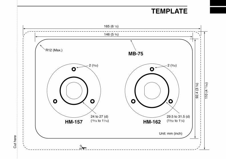
TEMPLATE
HM-157 HM-162
Unit: mm (inch)
R12 (Max.)MB-75
Cut
her
e

!IC-M504-1.qxd 06.3.28 9:03 AM Page 72 (1,1)

MEMO

1-1-32 Kamiminami, Hirano-ku, Osaka 547-0003, Japan
A-6483H-1US-qPrinted in Japan© 2006 Icom Inc.