Embed Size (px)
Citation preview
IM300
Operational Manual

TABLE OFCONTENTS1. INTRODUCTIONS..................................................................................................11.1. FUNCTION SPECIFICATION.................................................................................... 11.2. FEATURES.............................................................................................................1
2. THE INSTALLATION, WIRING AND CONFIGURATION.............................32.1. DIMENSIONS AND INSTALLATION......................................................................... 32.2. WIRING AND CONFIGURATION............................................................................. 6
3. OPERATING INSTRUCTIONS...........................................................................113.1. BUTTON OPERATION........................................................................................... 123.2. DATA READ(NON SOE)................................................................................. 133.3. PARAMETER SETTINGS........................................................................................333.4. LOCALOPERATION.............................................................................................493.5. SOE AND STATISTIC INQUIRY.............................................................................534.1. MODBUS PROTOCOL OVERVIEW........................................................................614.1.1 THE TRANSMISSION FORMAT............................................................................ 614.1.2 THE FRAME FORMAT........................................................................................ 624.2. COMMUNICATION PROTOCOL ADDRESS TABLE AND DESCRIPTION..................... 644.3. EXPLANATION OF REGISTER ADDRESS................................................................904.4. SOE COMMUNICATION FORMAT DESCRIPTION..................................................97
5. TRANSPORTATION AND STORAGE............................................................. 100APPENDIX............................................................................................................... 101A. THE DEFAULT VALUE.......................................................................................... 101B. TECHNICAL INDICATORS..................................................................................... 103C. ORDER INSTRUCTIONS.........................................................................................105

IM300 Intelligent Power Monitoring Instrument
1
1. Introductions
1.1. Function Specification
IM300 is an intelligent multipurpose power parameter monitoring and control
device which has an extensive range of applications in 6~35kV or 0.4kV power
systems. It has the data acquisition, control and statistical functions, such as electrical
parameters measurement, calculation and statistics, fault records, 2 ~ 31st
harmonics monitoring function, 4-ch digital inputs and 2-ch relay outputs, 1-ch
4~20mA DC transmission output, over-limit alarm and other functions. IM300 is
equipped with RS485 communications and MODBUS-RTU protocol for integration
into any power monitoring and control system. The appearance is shown in fig 1.1.1.
Fig 1.1.1 The appearance of IM300
1.2. Features
1.2.1.IM300 functions
Applied in 3-phase 3-wire system and 3-phase 4-wire system . It can measure
and calculate 3-phase voltage, 3-phase current, Zero-sequence current, active
power, reactive power, apparent power, power factor, system frequency, active
energy and reactive energy.
Harmonic distortion ratio of voltage and current.( Including total harmonic
distortion ratio THD, odd harmonic distortion ratio , even harmonic distortion
ratio), 2~31st harmonic occupancy of voltage, 2~31st harmonic occupancy of
current, the RMS of voltage and current base wave, etc.
2-ch relay control outputs.

IM300 Intelligent Power Monitoring Instrument
2
4-ch digital inputs, up to 32 SOE (the Sequence of Events) of digital inputs
can be recorded.
1-ch 4 ~ 20mA DC transmission output which can be associated with any
voltage, current, power.
forward/reverse total active energy, reactive energy in four quadrants.
Multi-rate energy statistics (4 rates, 48 time-periods) of the forward/reverse
total active energy, reactive energy in four quadrants.
The value and occurrence time of the maximum forward/reverse active and
reactive power demand. The maximum/minimum value and occurrence time of
the voltage, current, frequency, power factor, active power, reactive power,
apparent power.
Unbalanced degree of three-phase voltage and current.
The over limit alarm function, such as over-current, zero-current, grounding,
low-voltage, over-voltage, low-frequency, over- frequency, low-power factor, can
be associated with relay outputs.
Checking and modifying the various electrical parameters, running status and
controlling the relays locally.
Communication protocol is MODBUS-RTU.
The clock can be set manually.
Note: The above functions are selected according to the specific models of themeter (see appendix C).
1.2.2.High safety and reliability
IM300 can run steadily in the complex power system.
Electrostatic discharge immunity test : level 3
Electric fast transient immunity test : level 3
The surge immunity test : level 3
Frequency magnetic field immunity test : level 3
Oscillation wave immunity test : level 3
The IP level of panel: IP50, the IP level of shell: IP20
1.2.3.Easy installation
IM300 dimensions conform DIN96 × 96 standard. It can be mounted on the

IM300 Intelligent Power Monitoring Instrument
3
cabinet panel easily.
1.2.4.The wiring of system
3-phase 4-wire 3CT (3P4W 3CT)
3-phase 4-wire 1CT (3P4W 1CT)
3-phase 3-wire 3CT (3P3W 3CT)
3-phase 3-wire 2CT (3P3W 2CT)
3-phase 3-wire 1CT (3P3W 1CT)
1.2.5.The human-machine interface
The LCD screen can display various of information with bright backlighting. It’s
very easy to operate IM300 by the human-machine interface.
1.2.6.Application field
Medium and low voltage distribution system, intelligent switch cabinet, load
control system, industrial automation, building automation and Energy management
system.
2. The installation, wiring and configuration
This chapter details the installation method, wiring and configuration of the
IM300. Please read carefully before installation.
2.1. Dimensions and installation2.1.1. Dimensions of mechanical devices
Front view Side View
IM300 Intelligent Power Monitoring Instrument
4
Fig 2.1.1. Device size fig. (Unit: mm)
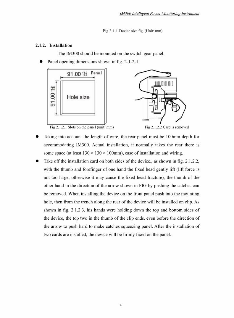
2.1.2. Installation
The IM300 should be mounted on the switch gear panel.
Panel opening dimensions shown in fig. 2-1-2-1:
Fig 2.1.2.1 Slots on the panel (unit: mm) Fig 2.1.2.2 Card is removed
Taking into account the length of wire, the rear panel must be 100mm depth for
accommodating IM300. Actual installation, it normally takes the rear there is
some space (at least 130 × 130 × 100mm), ease of installation and wiring.
Take off the installation card on both sides of the device., as shown in fig. 2.1.2.2,
with the thumb and forefinger of one hand the fixed head gently lift (lift force is
not too large, otherwise it may cause the fixed head fracture), the thumb of the
other hand in the direction of the arrow shown in FIG by pushing the catches can
be removed. When installing the device on the front panel push into the mounting
hole, then from the trench along the rear of the device will be installed on clip. As
shown in fig. 2.1.2.3, his hands were holding down the top and bottom sides of
the device, the top two in the thumb of the clip ends, even before the direction of
the arrow to push hard to make catches squeezing panel. After the installation of
two cards are installed, the device will be firmly fixed on the panel.

IM300 Intelligent Power Monitoring Instrument
5
Fig 2.1.2.3 Fixed on the panel by the mounting blocks
2.1.3. Safety Warnings
警告!只能由专业电工进行安装。
Warning! Installation by person with electrotechnicalexpertise only.
Warnung! Installation nur durch elektrotechnische Fachkraft.
Avvertenza! Fare installare solo da un elettricista qualificato.
Avertissement! Installation uniquement par des personnes qualifiées en
électrotechnique.
¡Advertencia! La instalacióndeberáserrealizadaúnicamentepor
electricistasespecializados.
www.abb.com/lowvoltage/directives
2.1.4. Installation Notes
Inside of the product is no user-adjustable components, do not open during
installation.
Installation with power on is not allowed..
Run should meet the ambient temperature -25 ℃ ~ + 70 ℃, humidity 0 to 95%,
atmospheric pressure 70kPa ~ 106kPa. Avoid placing the device into strong
source of interference, radiation, heat sources and dusty environment.
IM300 Intelligent Power Monitoring Instrument
6
2.2. Wiring and Configuration
2.2.1. Terminal Definition
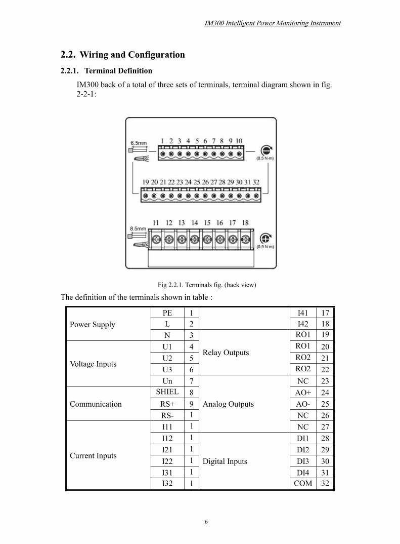
IM300 back of a total of three sets of terminals, terminal diagram shown in fig.2-2-1:
Fig 2.2.1. Terminals fig. (back view)
The definition of the terminals shown in table :
Power SupplyPE 1 I41 17L 2 I42 18N 3
Relay Outputs
RO1 19
Voltage Inputs
U1 4 RO12
20U2 5 RO2
121
U3 6 RO22
22Un 7
Analog Outputs
NC 23
CommunicationSHIELD
8 AO+ 24RS+ 9 AO- 25RS- 1
0NC 26
Current Inputs
I11 11
NC 27I12 1
2
Digital Inputs
DI1 28I21 1
3DI2 29
I22 14
DI3 30I31 1
5DI4 31
I32 16
COM 32

IM300 Intelligent Power Monitoring Instrument
7
Note: ① IM300 device varies according to the specific models (see appendix C. Order
description). The corresponding terminals that do not have functions are empty (NC).
② In the 3-phase 4-wire system, the Un is connected to the voltage common end; In
3-phase 3-wire system, the Un is connected to B-phase voltage. DI means Digital
Input; RO means Relay Output;Transmitter output is self-powered, AO + is forward
current output , AO- is reverse current output.
2.2.2. Power supply wiring
Power supply range of IM300 is 85 ~ 265VAC or 85 ~ 265VDC, it
suggested a independent power supply wiring as shown in fig. 2-2-2.
1 2 3
2A fuseSupply voltage85~265VAC/DC
Earth
PE L N
Fig 2.2.2. Power wiring diagram
2.2.3. Electric wiring 3-phase 4-wire system: 3CT
Fig 2.2.3.1 3P4W+3CT
3-phase 4-wire system: 1CT

IM300 Intelligent Power Monitoring Instrument
8
4 5 76 11 12 4 5 6 7 11 12
N
C
B
A
N
C
B
A
Fig 2.2.3.2 3P4W+1CT
3-phase 3-wire system: 3CT
Fig2.2.3.3 3P3W+3CT
3-phase 3-wire system: 2CT
Fig 2.2.3.4 3P3W/3PT+2CT
3-phase 3-wire system: 1CT
IM300 Intelligent Power Monitoring Instrument
9
Fig 2.2.3.5 3P3W+1CT
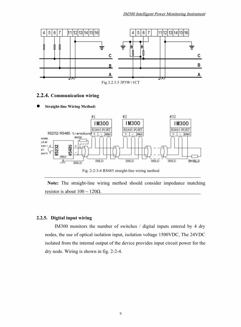
2.2.4. Communication wiring
Straight-line Wiring Method:
Fig. 2-2-3-6 RS485 straight-line wiring method
Note: The straight-line wiring method should consider impedance matching
resistor is about 100 ~ 120Ω.
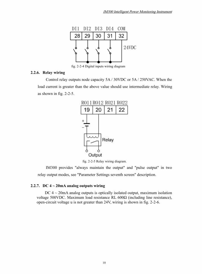
2.2.5. Digital input wiring
IM300 monitors the number of switches / digital inputs entered by 4 dry
nodes, the use of optical isolation input, isolation voltage 1500VDC, The 24VDC
isolated from the internal output of the device provides input circuit power for the
dry node. Wiring is shown in fig. 2-2-4.
IM300 Intelligent Power Monitoring Instrument
10
28 29 30 31 32DI1 DI2 DI3 DI4 COM
24VDC
fig. 2-2-4 Digital inputs wiring diagram
2.2.6. Relay wiring
Control relay outputs node capacity 5A / 30VDC or 5A / 250VAC. When the
load current is greater than the above value should use intermediate relay. Wiring
as shown in fig. 2-2-5.
fig. 2-2-5 Relay wiring diagram.
IM300 provides "always maintain the output" and "pulse output" in two
relay output modes, see "Parameter Settings seventh screen" description.
2.2.7. DC 4 ~ 20mA analog outputs wiring
DC 4 ~ 20mA analog outputs is optically isolated output, maximum isolationvoltage 500VDC. Maximum load resistance RL 600Ω (including line resistance),open-circuit voltage u is not greater than 24V, wiring is shown in fig. 2-2-6.

IM300 Intelligent Power Monitoring Instrument
11
AO+ AO- NC NC
24 25 26 27
RL
u
fig. 2-2-6 DC analog outputs wiring diagram
2.2.8. Wiring Precautions
The conductor cross section of the connecting wire to the device should meet the
following requirements: the cross section of current wires is not less than 2.5
mm2, the cross section of voltage wires is not less than 1.0 mm2.
Communication lines must be shielded twisted pair, communication line RS485 +,
RS485- can not be reversed.
The wires of power supply and voltage input must be connected with 2A fuse in
series..
To reduce the impact of current at startup, it is recommended each power cord
does not exceed 40 devices.
When the communication connection using the linear connection, respectively
access line should match 100 ~ 120Ω resistor is located between the beginning
and the ending of the communication cable at the RS485 + and RS485- terminals.
Baud rate is 9600bps, the cable length <1200 meters.
The maximum load of the analog outputs includes the line resistance. Be careful
when wiring.
3. Operating Instructions
This chapter details IM300 man-machine interface, including how to read the
data, set parameters, and local operations.Note: IM300 means depending on each particular model (see Appendix C. ordering), does
not have a corresponding function corresponding to the interface does not display.
IM300 Intelligent Power Monitoring Instrument
12
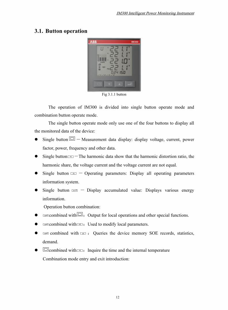
3.1. Button operation
Fig 3.1.1 button
The operation of IM300 is divided into single button operate mode and
combination button operate mode.
The single button operate mode only use one of the four buttons to display all
the monitored data of the device:
Single button -Measurement data display: display voltage, current, power
factor, power, frequency and other data.
Single button -The harmonic data show that the harmonic distortion ratio, the
harmonic share, the voltage current and the voltage current are not equal.
Single button - Operating parameters: Display all operating parameters
information system.
Single button - Display accumulated value: Displays various energy
information.
Operation button combination:
combined with :Output for local operations and other special functions.
combined with :Used to modify local parameters.
combined with : Queries the device memory SOE records, statistics,
demand.
combined with :Inquire the time and the internal temperature
Combination mode entry and exit introduction:

IM300 Intelligent Power Monitoring Instrument
13
In the single button mode, press the combinatorial button at the same time and
then loosen, you can enter the corresponding combinatorial button function; use the
combinatorial button again you will go back to the single button display screen
(except the fourth button combination).
3.2. Data read(non SOE)
Display content Explanation
Four rows of in the data displayfield
Display measurement data, including: current, voltage, power,power factor, frequency and so on. Second, display parameters,SOE, time, local operations, etc.
The “a“, “b“, “c“ denotes a ,b and C-phase respectively;“∑“denotes summation; “Avg” denotes average; “-” denotesminus; “n” denotes zero-sequence
Three at the top left cornerConsists of English semantic abbreviations, used to indicate thecurrent interface meaning: such as voltage 'U', current 'I', etc.
Current load size indication.The actual load current is relative to the percentage of rated loadcurrent, from left to right, respectively, Ia/Ib/Ic.
Digital identifier: onoff
The switch volume identification indicates the state of input ofthe corresponding switch in 1 ~ 4(on or off).
Load character identifierInductance identifier(upper) indicate inductive loadCapacitance identifier(below) indicate capacitive load
Communication status identifier
Display this identifier indicates the communication work innormalDoes not display this identifier indicate the communication out ofwork
More warning signsDisplay this sign indicates that there is more alarm, no indicationthat there is no more alarm.
Switch quantization SOE identification. Display this sign indicates that there is a switch quantifier SOErecord in memory, which does not show that there is no switchquantifier SOE record in memory.
10 little in data accumulateddisplay field
Display energy, temperature of the equipment and time.

IM300 Intelligent Power Monitoring Instrument
14
Units: kVA MkW% MkvarMkVA HzkWh kvarh
The unit of measuring data:Current: A, KA;Voltage: V, KV;Active power: W, KW, MW;Reactive power: Var, KVar, MVar;Apparent power: VA, KVA, MVA;Frequency: Hz;Percentage: %;Active energy: KWh;Reactive energy: Kvarh;
Total sharp peak shoulder off-peakelectricity demand
Electrical ruler type and demand tips
Table 3-1
3.2.1. Run the display of measurement data
In either a single bond display press button, the measurement data
display area will show the measured data. Time display area (bottom row small )
remains unchanged.
In the measurement data display mode, press button until the top left of
the screen display after the words 'UP', then press button to
scroll upward; press button until the top left of the screen
displays the word 'DWN', then scroll down to press button.
Screen 1: Display the phase voltage Ua, Ub, Uc and
UAvg (the average value of three phase voltages).
As shown in fig. 3.2.1: Ua = 221.1V; Ub = 221.1V;
Uc = 221.0V; UAvg = 221.1V.
Note: Only when the 3-phase 4-wire system wiring for the
displayed page, otherwise the page is not displayed.
Screen2 : Display the phase current Ia, Ib, Ic and
IAvg(the average value of three phase currents).
As shown in fig. 3.2.2: Ia = 3.286A; Ib = 3.375A;
Ic = 3.066A; IAvg = 3.243A.
Fig 3.2.1. 3-phase voltage
Fig 3.2.2 3-phase current

IM300 Intelligent Power Monitoring Instrument
15
Fig 3.2.3 line voltage
Screen 3: Display the line voltage Uab,Ubc,Uca and Uavg (theaverage value of line voltage).The parameter value is shown in fig 3.2.3:
Uab=382.8V;Ubc=382.9V;Uca=383.0V;UAvg=382.9V
Screen 4:Display the phase current Ia,Ib,Ic and In( the zero-sequence current) .
The parameter value is shown in fig 3.2.4:Ia=3.286A;Ib=3.375A;Ic=3.066A;In=0.211A
Screen 5: when the connection mode is set as 3-phase4-wire,each phase power factor PFa, PFb, PFc and total power factorPF displayed on the screen.
PF=0.988; PFa=0.987;PFb=0.988;PFc=0.989
When the connection mode is set as 3-phase 3-wire, total powerfactor PF displayed only.
PF=0.988The symbol of power factor complies with IEC symbolregulation
Fig 3.2.4 3-phase current and zero-sequence
Fig 3.2.5 Power factor
IM300 Intelligent Power Monitoring Instrument
16
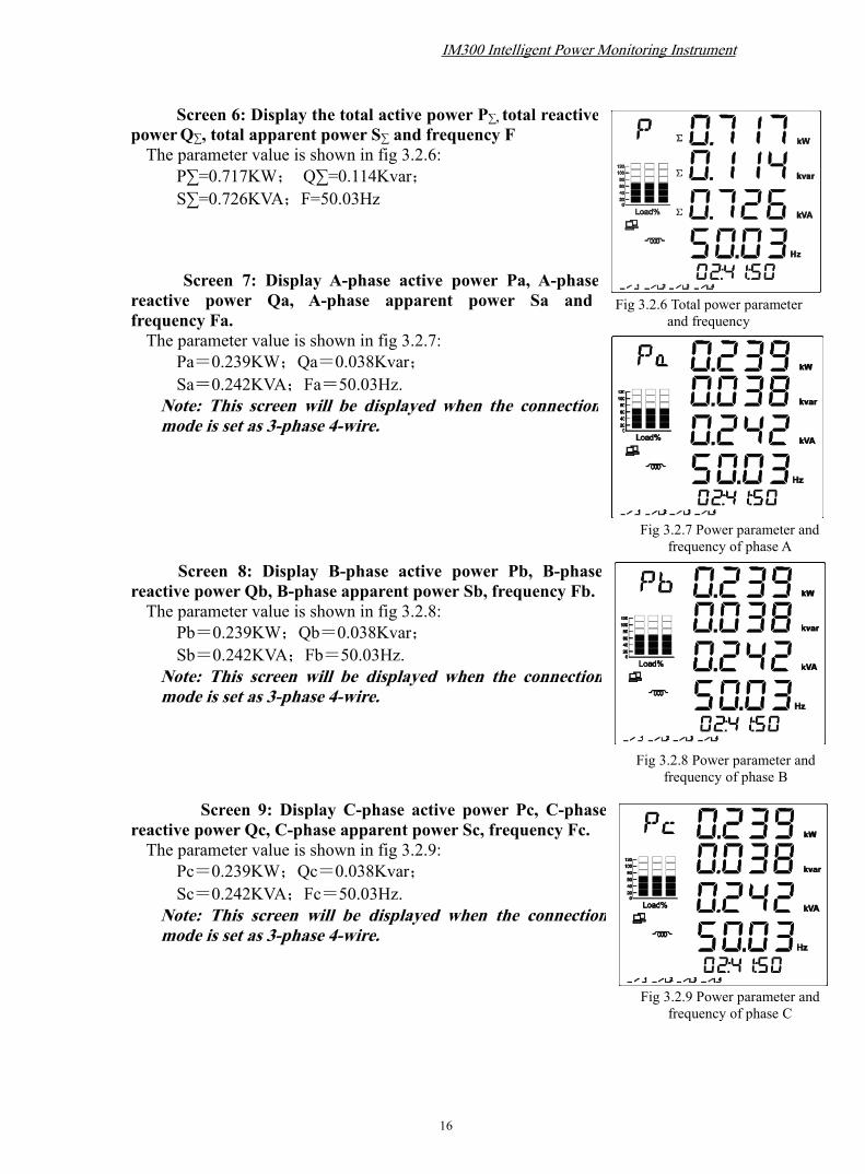
Screen 6: Display the total active power P∑, total reactivepowerQ∑, total apparent power S∑ and frequency FThe parameter value is shown in fig 3.2.6:
P∑=0.717KW; Q∑=0.114Kvar;S∑=0.726KVA;F=50.03Hz
Screen 7: Display A-phase active power Pa, A-phasereactive power Qa, A-phase apparent power Sa andfrequency Fa.The parameter value is shown in fig 3.2.7:
Pa=0.239KW;Qa=0.038Kvar;Sa=0.242KVA;Fa=50.03Hz.
Note: This screen will be displayed when the connectionmode is set as 3-phase 4-wire.
Screen 8: Display B-phase active power Pb, B-phasereactive power Qb, B-phase apparent power Sb, frequency Fb.The parameter value is shown in fig 3.2.8:
Pb=0.239KW;Qb=0.038Kvar;Sb=0.242KVA;Fb=50.03Hz.
Note: This screen will be displayed when the connectionmode is set as 3-phase 4-wire.
Screen 9: Display C-phase active power Pc, C-phasereactive power Qc, C-phase apparent power Sc, frequency Fc.The parameter value is shown in fig 3.2.9:
Pc=0.239KW;Qc=0.038Kvar;Sc=0.242KVA;Fc=50.03Hz.
Note: This screen will be displayed when the connectionmode is set as 3-phase 4-wire.
Fig 3.2.8 Power parameter andfrequency of phase B
Fig 3.2.6 Total power parameterand frequency
Fig 3.2.7 Power parameter andfrequency of phase A
Fig 3.2.9 Power parameter andfrequency of phase C

IM300 Intelligent Power Monitoring Instrument
17
3.2.2. Harmonic distortion ratio and harmonic components
In either a single bond display press button display
area harmonic distortion ratio, harmonic components,voltage
/current unbalanced degree and K-factor of current, etc.In the harmonic content display mode, press button until the
top left of the screen display after the words 'UP', then press
button to scroll upward; press button until the top left of the
screen display after the words 'DWN', press button to scroll
down.
Screen 1: Display the total harmonic distortion ratio of3-phase voltage“H-U” displayed at the left top corner of the screen .When the connection mode is set as 3-phase 4-wire system,3-phase voltage Ua, Ub, Uc of THD is shown as fig 3.2.10:
THD_Ua=0.6%;THD_Ub=0.6%;
THD_Uc=0.6%;
When the connection mode is set as 3-phase3-wire system, 3-phase line voltage Uab, Ubc,Uca of THD is shown as fig 3.2.11:
THD_Uab=0.6%;THD_Ubc=0.6%;
THD_Uca=0.6%;
Screen 2: Display the total harmonic distortion ratio of3-phase current and zero-sequence current.“H-I” displayed at the left top corner of the screen.The parameters are shown in fig 3.2.12:
THD_Ia=0.6%;THD_Ib=0.6%;
THD_Ic=0.6%;THD_In=0.6%;
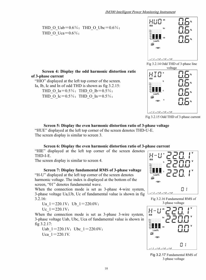
Screen 3: Display the odd harmonic distortion ratio of3-phase voltage“HUO” displayed at the left top corner of the screen.when the connection mode is set as 3-phase 4-wire system,
3-phase voltage Ua, Ub, Uc of odd THD is shownas fig 3.2.13:
THD_O_Ua=0.6%;THD_O_Ub=0.6%;
THD_O_Uc=0.6%;when the connection mode is set as 3-phase 3-wire system,3-phase line voltage Uab, Ubc, Uca of odd THD is shownin fig 3.2.14:
Fig 3.2.11 THD of 3-phase linevoltage
Fig 3.2.10 THD of 3-phase voltage
Fig 3.2.12 THD of 3-phase currentand zero-sequence current
Fig 3.2.13 Odd THD of 3-phase voltage
IM300 Intelligent Power Monitoring Instrument
18
THD_O_Uab=0.6%;THD_O_Ubc=0.6%;
THD_O_Uca=0.6%;
Screen 4: Display the odd harmonic distortion ratioof 3-phase current“HIO” displayed at the left top corner of the screen.Ia, Ib, Ic and In of odd THD is shown as fig 3.2.15:
THD_O_Ia=0.5%;THD_O_Ib=0.5%;
THD_O_Ic=0.5%;THD_O_In=0.5%;
Screen 5: Display the even harmonic distortion ratio of 3-phase voltage“HUE” displayed at the left top corner of the screen denotes THD-U-E.The screen display is similar to screen 3.
Screen 6: Display the even harmonic distortion ratio of 3-phase current“HIE” displayed at the left top corner of the screen denotesTHD-I-E.The screen display is similar to screen 4.
Screen 7: Display fundamental RMS of 3-phase voltage“H-U” displayed at the left top corner of the screen denotesharmonic voltage. The index is displayed at the bottom of thescreen, “01” denotes fundamental wave.When the connection mode is set as 3-phase 4-wire system,3-phase voltage Ua,Ub, Uc of fundamental value is shown in fig3.2.16:
Ua_1=220.1V;Ub_1=220.0V;Uc_1=220.1V;
When the connection mode is set as 3-phase 3-wire system,3-phase voltage Uab, Ubc, Uca of fundamental value is shown infig 3.2.17:
Uab_1=220.1V;Ubc_1=220.0V;Uca_1=220.1V.
Fig 3.2.15 Odd THD of 3-phase current
Fig 3.2.16 Fundamental RMS of3-phase voltage
Fig 3.2.14 Odd THD of 3-phase linevoltage
Fig 3.2.17 Fundamental RMS of3-phase voltage

IM300 Intelligent Power Monitoring Instrument
19
Screen 8 to screen 37: Display the 2~31th harmonic ratioof 3-phase voltage in turn“H-U” displayed at the left top corner of the screen denotesharmonic voltage. The index is displayed at the bottom of thescreen.When the connection mode is set as 3-phase 4-wire system,
3-phase voltage Ua, Ub, Uc of second harmonic ratio is shown infig 3.2.18:
HP_2_Ua=0.4%;HP_2_Ub=0.4%;
HP_2_Uc=0.4%;
When the connection mode is set as 3-phase 3-wiresystem,3-phase line voltage Uab, Ubc, Uca of secondharmonic ratio is shown in fig 3.2.19:
HP_2_Uab=0.4%;HP_2_Ubc=0.4%;
HP_2_Uca=0.4%;
Screen 38: Display the fundamental value of3-phase current and zero-sequence current“H-I” displayed at the left top corner of the screen denotesharmonic voltage.The index is displayed at the bottom of thescreen, “01” denotes fundamental wave. Fundamental value of3-phase current is shown in fig 3.2.20:
Ia_1=5000A;Ib_1=4999A;Ic_1=5001A;In_1=102A;
Screen 39 to screen 68: Display the 2~31th harmonicratio of 3-phase current in turn:“H-I” displayed at the left top corner of the screen denotesharmonic current. The index is displayed at the bottom of thescreen.3-phase current Ia, Ib, Ic and zero-sequence current In of secondharmonic is shown in fig 3.2.21:
HP_2_Ia=0.5%;HP_2_Ib=0.5%;
HP_2_Ic=0.5%;HP_2_In=0.5%;
Fig 3.2.18 2th harmonic ratio of 3-phasevoltage
Fig3.2.19 2 the harmonic ratio of 3-phase linevoltage
Fig 3.2.20 Fundamental value of current
Fig 3.2.21 2th harmonic ratio of 3-phasecurrent

IM300 Intelligent Power Monitoring Instrument
20
Fig 3-2-24 Communicationparameters
Screen 69: Display voltage imbalance and currentimbalance“UNB” displayed at the left top corner of the screen denotesunbalanced degree. See in fig 3.2.22:
Unbalanced degree of current:10.8%;
Unbalanced degree of voltage:9.6%;
3.2.3. Display operating parameters
Press button operating parameters displayed on the screen in either a
single bond display.
After long press button until the top left of the screen displays the word 'DWN';
in button operating parameters display mode, press button until the top left of the
screen display after the words 'UP', then press the button to scroll up press button
to scroll down.
Screen 1:Communication parameters
The upper left corner of the screen displays "PAR"
parameter indicates the word (parameter), the top of the screen
displays the word "COMM" indicates the communication. As
shown in fig. 3-2-24: Address Number 16, the baud rate is 9.6k,
transport format code 1.
Transmission Format Code explanation:
Code number Expression0 1 start bit,8 data bits,no parity check,2 end bits1 1 start bit, 8 data bits, odd check, 1 end bit.2 1start bit, 8 data bits, even check, 1 end bit.3 1 start bit,8 data bits,no parity check,1 end bit
Note: The default value of address number is 254 baud rate is 9.6k, transport
format code is 0.
Fig3.2.22 Voltage imbalance andcurrent imbalance

IM300 Intelligent Power Monitoring Instrument
21
Fig 3-2-26 PT ratio
Fig 3-2-28 Zero-sequence CT ratio
Fig 3-2-25 Wiring Systems
Fig 3-2-27 CT ratio
Screen 2:SystemWiring
The upper display shows "SYS" the word that the systemwiring, as shown in fig. 3-2-25: The system wiring for the3-phase 4-wire system, 3PT, 3CT.
Note: The factory default is 3P4L, 3PT, 3CT.
Screen 3:PT ratio
The upper display shows "PT" word represents PT ratio.As shown in fig. 3-2-26: PT secondary rating is 220V, PT
primary rating is 1000V.Note: The factory default value, PT primary rating is 220V, PT
secondary rating is 220V.
Screen 4:CT ratio
The upper display shows "CT" indicates the CT ratio. Asshown in fig. 3-2-27: CT secondary rating two options for atotal is1A and 5A, CT primary rating is 100A.
Note: The factory default values, CT primary rating is 5000A,CT secondary rating is 5A.
Screen 5:Zero-sequence CT ratio
The upper display shows "CT0" word for zero-sequence CT
ratio. As shown in fig. 3-2-28: CT0 secondary rating two options
for a total is 1A and 5A, CT0 primary rating is 100A.Note: The factory default value, CT0 primary rating is 5000A,
CT0 secondary rating is 5A.
Screen 6:Direction of CT wiring and system frequency

IM300 Intelligent Power Monitoring Instrument
22
Fig 3-2-29 Setting CT wiring system frequencyand direction
Fig 3-2-30 Relay output Mode setting
Fig 3-2-31Relay output pulse width
The upper display shows "SYS2" word represents 2 system parameters,
including direction of CT wiring and system frequency. As shown in fig. 3-2-29.
The first line shows ABC, used to represent the respective
second row are A, B, C 3-phase CT.
The second line represents CT wiring direction: from left to
right direction A, B, C 3-phase CT, and 0 represents a forward
direction, represents the opposite direction.
The third line represents the system frequency: 50 / 60Hz
optionally, It’s the frequency of analog capture when no
voltage inputs..
Screen 7:Relay output mode
The upper display shows "RO-M" word indicates output
mode.
As shown in fig. 3-2-30: output mode 1.
Output mode 1: relay output for the pulse output. That relay
after receiving the closing instructions, the node is closed, a
certain time delay (relay output pulse width, see parameter setting eighth screen) is
disconnected.
Output mode 2: relay output is self-maintained. Ie after receiving the closing
instructions, the output node is closed; after receiving the opening command, output
node disconnected.Note: The factory default value, the output mode 1.
Screen 8: Relay output pulse width
The upper display shows "RO-T" word indicates relay
output pulse width in milliseconds.
As shown in fig. 3-2-31: Relay output pulse width is
2000 milliseconds.Note: The factory default value, the relay output pulse width is 2000 milliseconds.
Only when the output mode is selected as mode 1, that relay output pulse type, in order
to enter this page.

IM300 Intelligent Power Monitoring Instrument
23
fig. 3-2-33 Backlight lighting time
Fig 3-2-34 Statistical interval of theenergy max/min value
Screen 9 : Transmission output
parameters
The upper display shows "AO" the wordindicates the transmitter output parameters.
The first line indicates unidirectional /bidirectional: 0 for unidirectional, 1 forbidirectional;
The second line indicates the type ofassociation, as described in the ninth parametersetting screen;
The third line indicates the electric parameterssent to the output range of the association.
Screen 10:Time of back-light lighting
The upper display shows "Ld-T" word represents the
time of back-light lighting.
As shown in fig. 3-2-33: the time of back-light lighting is
30 minutes, that is, within 30 minutes of no buttons are
pressed, the back-light lighting automatically turns off; When
it is zero, indicating that the back-light lighting is on.
Note: the time of back-light lighting default is 5 minutes.
Screen 11: Statistical interval of the energy max/min
value
The upper display shows "S - T" word indicates the statistical
interval of the energy max/min value.
As shown in fig. 3-2-34: the time of statistical interval of
energy max/min value is 1440 minutes.
Note: The statistical interval of the energy max/min default value is 10
minutes.
Fig 3-2-32 Transmission output settings page
IM300 Intelligent Power Monitoring Instrument
24
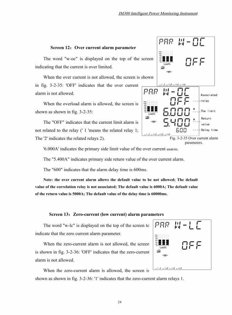
Screen 12:Over current alarm parameter
The word "w-oc" is displayed on the top of the screen
indicating that the current is over limited.
When the over current is not allowed, the screen is shown
in fig. 3-2-35: 'OFF' indicates that the over current
alarm is not allowed.
When the overload alarm is allowed, the screen is
shown as shown in fig. 3-2-35:
The "OFF" indicates that the current limit alarm is
not related to the relay (' 1 'means the related relay 1;
The '2' indicates the related relays 2).
'6.000A' indicates the primary side limit value of the over current alarm.
The "5.400A" indicates primary side return value of the over current alarm.
The "600" indicates that the alarm delay time is 600ms.
Note: the over current alarm allows the default value to be not allowed; The default
value of the correlation relay is not associated; The default value is 6000A; The default value
of the return value is 5000A; The default value of the delay time is 60000ms.
Screen 13:Zero-current (low current) alarm parameters
The word "w-lc" is displayed on the top of the screen to
indicate that the zero current alarm parameter.
When the zero-current alarm is not allowed, the screen
is shown in fig. 3-2-36: 'OFF' indicates that the zero-current
alarm is not allowed.
When the zero-current alarm is allowed, the screen is
shown as shown in fig. 3-2-36: '1' indicates that the zero-current alarm relays 1.
Fig. 3-2-35 Over current alarmparameters.

IM300 Intelligent Power Monitoring Instrument
25
Fig. 3-2-36 Zero current alarm parameters
Fig. 3-2-37 Over ground current alarmparameters.
'1.000A' indicates the primary side limit value
of the zero-current alarm.
The '1.100A' represents the primary side return
value of the zero-current alarm.
The '600' indicates that the delay time of
zero-current is 600ms.
Note: the default value of zero-current alarmallows to be not allowed; The default value of the correlation relay is not associated; Thedefault value is 0A; The default value of the return value is 200A; The default value ofthe delay time is 60000ms.
Screen 14 : Over ground current alarm
parameters.
The word "w-et" is displayed on the top of the screen to
indicate the alarm parameters of over ground current.
When the over ground current alarm is not allowed, the
screen is shown in fig. 3-2-37: 'OFF' indicates that the over
ground current alarm is not allowed.
When the over ground current alarm is allowed,
the screen is shown as shown in fig. 3-2-37: '1'
indicates that the over ground current alarm relays 1.
'6.000A' represents the primary side limit value
of the over ground current alarm.
The '5.400A' indicates primary side return
value of the alarm.
The '600' indicates that the delay time of over
ground current is 600ms.
Note: the over ground current alarm allows the default value to be not allowed;The default value of the correlation relay is not associated; The default value is 6000A;The default value of the return value is 5000A; The default value of the delay time is60000ms.

IM300 Intelligent Power Monitoring Instrument
26
Fig. 3-2-38 Lower voltage alarm parameters.
Fig. 3-2-39 Over voltagealarm parameters.
Screen 15:Lower voltage alarm parameters.The word "w-lv" is displayed on the top of the screen,
indicating that the lower voltage alarm parameter.
When the lower voltage alarm is not allowed, the screen
is shown in fig. 3-2-38: 'OFF' indicates that the lower voltage
alarm is not allowed.
When the low voltage alarm is allowed, the screen is
shown as shown in fig. 3-2-38:
The "1" indicates that the lower voltage alarm
associated relay 1.
The '190.0V' indicates primary side limit value
of the lower voltage .
"200.0v" indicates primary side return value of
the lower voltage.
The '60.0' indicates that the lower voltage alarm
delay time is 60s.Note: the lower voltage alarm allows the default value to be not allowed; The
default value of the correlation relay is not associated; The default value is 0V; The
default value of the return value is 50V; The default value for delay time is 1800s.
Screen 16:Over voltage alarm parameter.
The word "w-ov" on the top of the screen indicates that
the over voltage alarm parameter.
When the over voltage alarm is not allowed, the screen
is shown in fig. 3-2-39: 'OFF' indicates that the over voltage
alarm is not allowed.
When the over voltage alarm is allowed, the
screen is shown in fig. 3-2-39:
The "1" indicates that the over voltage alarm
relays 1.
"200.0v" indicates the primary side limit value

IM300 Intelligent Power Monitoring Instrument
27
Fig. 3-2-40 Lower frequency alarmparameters.
of over voltage .
'190.0V' indicates primary side return value of the over voltage alarm.
'60.0' indicates that the over voltage alarm delay time is 60 seconds.Note: the over voltage alarm allows the default value to be not allowed; The default
value of the correlation relay is not associated; The default value is 260V. The default
value of the return value is 220V; The default value for delay time is 1800s.
Screen 17:Lower frequency alarm parameters
The word "w-lf" is displayed on the top of the screen to
indicate the lower frequency alarm parameters.
When the lower frequency is not allowed, the screen is
shown in fig. 3-2-40: 'OFF' indicates that the lower frequency
is not allowed.
When the lower frequency alarm is allowed,
the screen is shown as shown in fig. 3-2-40:
The "1" indicates that the lower frequency
alarm correlation relay 1.
The '47.00Hz' indicates that the primary side
limit value of lower frequency alarm.
'49.50Hz' indicates primary side return value
of lower frequency alarm.
The '60.0' indicates that the lower frequency of the alarm
delay time is 60s.Note: the lower frequency alarm allows the default value to be not allowed; The
default value of the correlation relay is not associated; The default value is 45.0Hz; The
default value of the return value is 46.0Hz; The default value for delay time is 1800s.
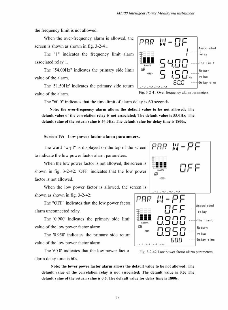
Screen 18:Over frequency alarm parameters.
The "w-of" is displayed above the screen to indicate the
frequency OF the alarm parameters.
When the over-frequency alarm is not allowed, the
screen display is shown in fig. 3-2-41: 'OFF' indicates that
IM300 Intelligent Power Monitoring Instrument
28
Fig. 3-2-41 Over frequency alarm parameters
Fig. 3-2-42 Low power factor alarm parameters.
the frequency limit is not allowed.
When the over-frequency alarm is allowed, the
screen is shown as shown in fig. 3-2-41:
The "1" indicates the frequency limit alarm
associated relay 1.
The "54.00Hz" indicates the primary side limit
value of the alarm.
The '51.50Hz' indicates the primary side return
value of the alarm.
The "60.0" indicates that the time limit of alarm delay is 60 seconds.Note: the over-frequency alarm allows the default value to be not allowed; The
default value of the correlation relay is not associated; The default value is 55.0Hz; Thedefault value of the return value is 54.0Hz; The default value for delay time is 1800s.
Screen 19:Low power factor alarm parameters.
The word "w-pf" is displayed on the top of the screen
to indicate the low power factor alarm parameters.
When the low power factor is not allowed, the screen is
shown in fig. 3-2-42: 'OFF' indicates that the low power
factor is not allowed.
When the low power factor is allowed, the screen is
shown as shown in fig. 3-2-42:
The "OFF" indicates that the low power factor
alarm unconnected relay.
The '0.900' indicates the primary side limit
value of the low power factor alarm
The '0.950' indicates the primary side return
value of the low power factor alarm.
The '60.0' indicates that the low power factor
alarm delay time is 60s.Note: the lower power factor alarm allows the default value to be not allowed; The
default value of the correlation relay is not associated; The default value is 0.5; Thedefault value of the return value is 0.6. The default value for delay time is 1800s.

IM300 Intelligent Power Monitoring Instrument
29
Fig 3-2-43 Hardware and softwareversion numbers
Screen 20:Hardware and software version numbers
Top of the screen to display "VER" word represents the
version number.
At right 3-2-43: "H 1.0" represents the hardware version is
version 1.0;
"S 1.0" indicates the software version number is version 1.0
3.2.4. Display energy
In the single button mode press button will display the energy.
Press the top left button until the screen shows word 'UP', then press
button to scroll upward; press button until the top left of the screen
display after the words 'DWN', press the button again will turn to next page.
Screen 1: Display the absolute value of total active
energy
“EP” displayed on the top , “∑” displayed in the
accumulated display area.
See in fig 3.2.44: Ep=5037.6 kWh
Screen 2: Display the absolute value of total reactive
energy
Top of the screen shows "total"and " Eq" word.
See in fig 3.2.45: Eq=37.1kvarh
Fig 3.2.44 Total active energy
Fig 3.2.45Total reactive energy
IM300 Intelligent Power Monitoring Instrument
30
Fig 3.2.46 The absolute value of total
forward active energy
Screen 3 to screen 5: Display the absolute value of per phase active energy
“EP” displayed on the top, “a”, “b”, “c” displayed in the accumulated display
area respectively. The screen display is similar to screen 1.Note: This screen will be displayed when the connection mode is set as 3-phase 4-wire.
Screen 6 to screen 8: Display the absolute value of per phase reactive energy“Eq” displayed on the top, “a”, “b”, “c” displayed in the accumulated display
area respectively. The screen display is similar to screen 2.Note: This screen will be displayed when the connection mode is set as 3-phase 4-wire.
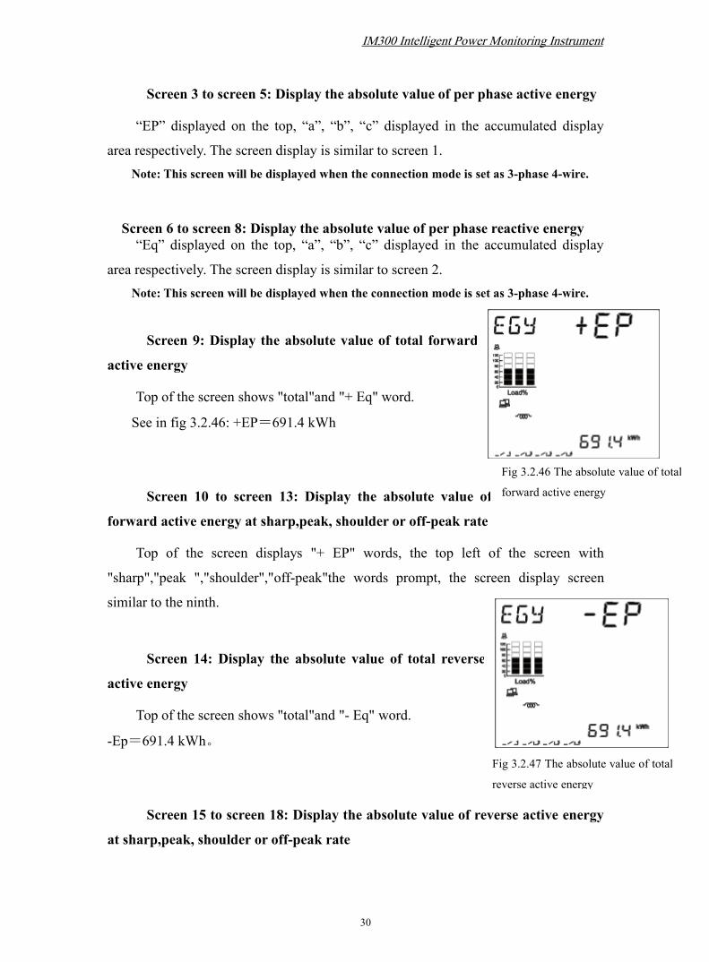
Screen 9: Display the absolute value of total forward
active energy
Top of the screen shows "total"and "+ Eq" word.
See in fig 3.2.46: +EP=691.4 kWh
Screen 10 to screen 13: Display the absolute value of
forward active energy at sharp,peak, shoulder or off-peak rate
Top of the screen displays "+ EP" words, the top left of the screen with
"sharp","peak ","shoulder","off-peak"the words prompt, the screen display screen
similar to the ninth.
Screen 14: Display the absolute value of total reverse
active energy
Top of the screen shows "total"and "- Eq" word.
-Ep=691.4 kWh。
Screen 15 to screen 18: Display the absolute value of reverse active energy
at sharp,peak, shoulder or off-peak rate
Fig 3.2.47 The absolute value of total
reverse active energy

IM300 Intelligent Power Monitoring Instrument
31
Top of the screen shows "-EP" words,rate types are sharp
peak, shoulder or off-peak ,the screen display screen similar to
the fourteenth.
Screen 19: Display the absolute value of total
forward reactive energy
Top of the screen shows "total"and "+ Eq" word.
See in fig 3.2.48: +Eq=571.1kvarh
Screen 20 to screen 23: Display the absolute value of forward reactive
energy at sharp,peak, shoulder or off-peak rate
Top of the screen displays "+ Eq" words,rate types are
sharp,peak, shoulder or off-peak, the screen display screen
similar to the nineteenth.
Screen 24: Display the absolute value of total reverse
reactive energy
“-Eq” displayed on the top, “∑” displayed in the accumulated display area.
See in fig 3.2.49: -Eq=571.1kvarh
Screen 25 to screen 28: Display the absolute value of
reverse reactive energy at sharp,peak, shoulder or off-peak
rate
“-Eq” displayed on the top.The screen
display is similar to screen 24.
Screen 29: Display the absolute value of
Fig 3.2.48 The absolute value of total
forward reactive energy
Fig 3.2.49 The absolute value of totalreverse reactive energy
Fig 3.2.50 The absolute value of the 1th quadrant total
reactive energy

IM300 Intelligent Power Monitoring Instrument
32
the 1th quadrant total reactive energy
Top of the screen shows "total"and "+ Eq" word.
See in fig 3.2.50: -Eq-1=11.1kvarh
Screen 30 to screen 33: Display the absolute value of the 1th quadrant
reactive energy at sharp,peak, shoulder or off-peak rate
“Eq-1” displayed on the top.the screen display is similar to screen 29.
Screen 34: Display the absolute value of the 4th quadrant total reactive
energy
“Eq-4” displayed on the top, the screen display is similar to screen 29.
Screen 35 to screen 38: Display the absolute value of the 4th quadrant
reactive energy at sharp,peak, shoulder or off-peak rate
“Eq-4” displayed on the top, the screen display is similar to screen 29.
Screen 39: Display the absolute value of the 2th quadrant total reactive
energy
“Eq-2” displayed on the top, the screen display is similar to screen 29.
Screen 40 to screen 43: Display the absolute value of the 2th quadrant
reactive energy at sharp,peak, shoulder or off-peak rate
“Eq-2” displayed on the top.the screen display is similar to screen 29.
Screen 44:Display the absolute value of the 3th quadrant total reactive
energy
“Eq-3” displayed on the top, the screen display is similar to screen 29.
IM300 Intelligent Power Monitoring Instrument
33
Fig 3-3-2 Is stored tips
Screen 45 to screen 48: Display the absolute value of the 3th quadrant
reactive energy at sharp,peak, shoulder or off-peak rate
“Eq-3” displayed on the top.The screen display is similar to screen 29.
3.3. Parameter SettingsIn the single button mode, you can enter the parameter setup mode by pressing“ ” and “ ” at the same time, “SET” will display at the left top corner of thescreen.
3.3.1. button function in parameter setup mode
Press “ ”, a bit of the parameter on the screen will twinkle, and the next bit will
twinkle by pressing again. You can press “ ” or “ ” to plus or minus the
value of the bit.
is the plus button, the flash bit will plus 1 when you press “ ” once.
is the minus button, the flash bit will minus 1 when you press “ ” once..
is the page down button and validated button. When parameter setting is
accomplished, press “ ” to validate the parameter, and “Y--N” (YES--NO) will
displays on the top of the screen. Press “ ” to select “Y” or “N”. Select “Y”
and press “ ”, the parameter will be saved , select “N” and press “ ”, the
parameter will be not saved.
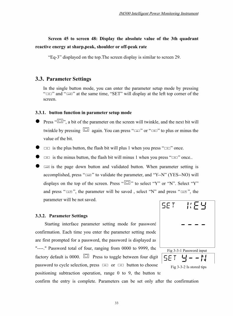
3.3.2. Parameter Settings
Starting interface parameter setting mode for password
confirmation. Each time you enter the parameter setting mode
are first prompted for a password, the password is displayed as
"----." Password total of four, ranging from 0000 to 9999, the
factory default is 0000. Press to toggle between four digit
password to cycle selection, press or button to choose
positioning subtraction operation, range 0 to 9, the button to
confirm the entry is complete. Parameters can be set only after the confirmation
Fig 3-3-1 Password input

IM300 Intelligent Power Monitoring Instrument
34
Fig 3-3-3 Parameter error
Fig. 3-3-4 Communicationparameter settings page
password, or to stay on this page.
When entering the parameter setting screen, as this page
parameter setting is completed, press the top button will be
prompted to save the current screen to set the parameters as shown
in fig. 3-3-2. "Y" on behalf of YES, that is, the set parameters are
stored, "N" on behalf of NO, that is not stored parameters. Press button to make
"Y" or "N" option, press button.
Select the parameters are valid after the "Y" and press the button to confirm ,
such as setting, then store the current parameters; if not legitimate, upper display
shows "ERR" word prompts, as shown, the parameter is not stored 3-3-3. At this point
press button to re-set parameters, scroll buttons can also be .
Note: No matter which screen parameter setting page, press the button and
button to exit the parameter setting mode,returns single button display mode. In
the parameter setting page, if you do not press button to activate the current
settings page, this page or activation button and did not press or button
parameter modification, then press button will scroll directly, this page is not
stored in the parameter. The screen will go back to the single button mode
automatically if there is no operation on buttons in ten minute. .
Press the top left button until the screen shows word 'UP', then press
button to scroll upward; press button until the top left of the screen display after
the words 'DWN', press the button down scroll.
Screen 1: Communication parameters settings
This page is used to set the IM300
communication address, baud rate and
transmission format. Top of the screen displays
the word "COMM", indicating the current page
for the communications parameter setting page.
As shown in fig. 3-3-4, communication
address range is 1 to 254; baud total of 1.2k,
2.4k, 4.8k, 9.6k, 19.2kbps five kinds to choose from;
there are four kind of transmission formats: 0,1,2,3. (The details refer to 3.2.3 display

IM300 Intelligent Power Monitoring Instrument
35
Fig 3-3-5 System wiring setup page
Fig 3-3-7 CT ratio settings page
system parameter, screen 1)
Screen 2:Wiring system settings
This page is used to set the system wiring. Top of the
screen displays the word "SYS", indicates that the current
page to the system wiring setup page, as shown in fig.
3-3-5.
There are five options:
Mode 1:3P4L 3PT 3CT
Mode 2:3P4L 3PT 1CT
Mode 3:3P3L 3PT(2PT) 3CT
Mode 4:3P3L 3PT(2PT) 2CT
Mode 5:3P3L 3PT(2PT) 1CT
Screen 3:PT Settings
This page is used to set the PT primary side
and the secondary side rated voltage value of PT.
Top of the screen displays the word "PT", it
indicates this page is PT settings page, as shown
in fig. 3-3-6.
PT secondary rating range from 100V to
220V, PT primary rating range from 100V to 35000V.
Screen 4:CT settings
This page is used to set the primaryside and secondary side rated current value ofCT. Top of the screen displays the word "CT",expressed this page as CT setup page, as shownin fig. 3-3-7.
CT secondary rating is 1A or 5A,CTprimary rating range from 1A to 9999A.
Note: primary side of the rated
IM300 Intelligent Power Monitoring Instrument
36
current value can not be less than the rated current value of the secondaryside.
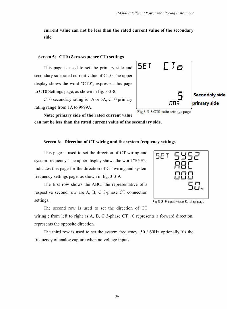
Screen 5:CT0 (Zero-sequence CT) settings
This page is used to set the primary side and
secondary side rated current value of CT.0 The upper
display shows the word "CT0", expressed this page
to CT0 Settings page, as shown in fig. 3-3-8.
CT0 secondary rating is 1A or 5A, CT0 primary
rating range from 1A to 9999A.
Note: primary side of the rated current valuecan not be less than the rated current value of the secondary side.
Screen 6:Direction of CT wiring and the system frequency settings
This page is used to set the direction of CT wiring and
system frequency. The upper display shows the word "SYS2",
indicates this page for the direction of CT wiring,and system
frequency settings page, as shown in fig. 3-3-9.
The first row shows the ABC: the representative of a
respective second row are A, B, C 3-phase CT connection
settings.
The second row is used to set the direction of CT
wiring ; from left to right as A, B, C 3-phase CT , 0 represents a forward direction,
represents the opposite direction.
The third row is used to set the system frequency: 50 / 60Hz optionally,It’s the
frequency of analog capture when no voltage inputs.

IM300 Intelligent Power Monitoring Instrument
37
Fig 3-3-10 Relay output mode settings page
Fig 3-3-11 Relay pulse width settings page
fig. 3-3-12 Transmission output settings page
Screen 7:Relay output mode settings
This page is used to set the relay output mode.
The upper display shows "RO-M" word, this page
indicates relay output mode settings page, as shown
in fig. 3-3-10.
There are two kinds of modes of relay output:Mode 1: relay output for the pulse output.
Mode 2: Relay output is self-maintained.
Screen 8:Relay output pulse width settings
When the relay is set to pulse output mode, the pageis used to set the output pulse width. The upper displayshows "RO-T" word to make prompt, as shown in fig.3-3-11.
A pulse width range of 50 to 20000 milliseconds.Note: Only when the output mode is selected as
mode 1,this screen is displayed, otherwise the pageis not displayed.
Screen 9:Transmission output parameter settings
This screen is used to set the
parameters of transmission output . "AO"
on top of the page donates transmission
output 。
The first row is used to set the
direction of AO, unidirectional or
bidirectional: 0 for unidirectional, 1 for
bidirectional.
The second row is used to set the associated type of AO. As shown in the table
below.
The third row indicates the range of the corresponding electrical parameter, and the
IM300 Intelligent Power Monitoring Instrument
38
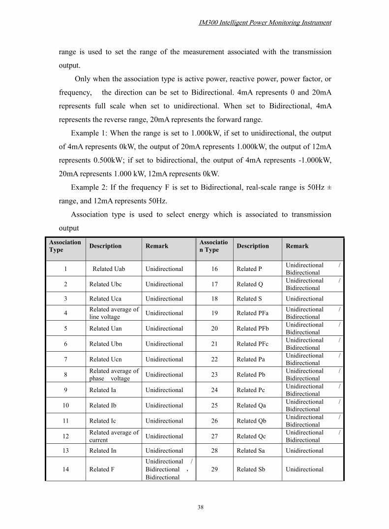
range is used to set the range of the measurement associated with the transmission
output.
Only when the association type is active power, reactive power, power factor, or
frequency, the direction can be set to Bidirectional. 4mA represents 0 and 20mA
represents full scale when set to unidirectional. When set to Bidirectional, 4mA
represents the reverse range, 20mA represents the forward range.
Example 1: When the range is set to 1.000kW, if set to unidirectional, the output
of 4mA represents 0kW, the output of 20mA represents 1.000kW, the output of 12mA
represents 0.500kW; if set to bidirectional, the output of 4mA represents -1.000kW,
20mA represents 1.000 kW, 12mA represents 0kW.
Example 2: If the frequency F is set to Bidirectional, real-scale range is 50Hz ±
range, and 12mA represents 50Hz.
Association type is used to select energy which is associated to transmission
output
AssociationType Description Remark Associatio
n Type Description Remark
1 Related Uab Unidirectional 16 Related P Unidirectional /Bidirectional
2 Related Ubc Unidirectional 17 Related Q Unidirectional /Bidirectional
3 Related Uca Unidirectional 18 Related S Unidirectional
4 Related average ofline voltage Unidirectional 19 Related PFa Unidirectional /
Bidirectional
5 Related Uan Unidirectional 20 Related PFb Unidirectional /Bidirectional
6 Related Ubn Unidirectional 21 Related PFc Unidirectional /Bidirectional
7 Related Ucn Unidirectional 22 Related Pa Unidirectional /Bidirectional
8 Related average ofphase voltage Unidirectional 23 Related Pb Unidirectional /
Bidirectional
9 Related Ia Unidirectional 24 Related Pc Unidirectional /Bidirectional
10 Related Ib Unidirectional 25 Related Qa Unidirectional /Bidirectional
11 Related Ic Unidirectional 26 Related Qb Unidirectional /Bidirectional
12 Related average ofcurrent Unidirectional 27 Related Qc Unidirectional /
Bidirectional13 Related In Unidirectional 28 Related Sa Unidirectional
14 Related FUnidirectional /Bidirectional ,Bidirectional
29 Related Sb Unidirectional

IM300 Intelligent Power Monitoring Instrument
39
Fig 3-3-13 Backlight timesettings page
Fig 3-3-14 Statistical interval ofelectric parameter maximum/minimum
value settings
Fig 3-3-15 Over current alarm parametersettings page
indicates 50Hz±range
15 Related PF Unidirectional /Bidirectional 30 Related Sc Unidirectional
Screen 10:Back-light time settings
This page is used to set the backlight lighting time. The
upper display shows the word "Ld-T", indicates that the
current page as the backlight time setting page, as shown in
fig. 3-3-13.
Backlight time range is from 0 to 30 minutes, when set
to 0, the backlight is on.
Screen 11:Statistical interval of electric parameter
maximum/minimum value settings
“S—T” on the top of the screen denotes the statisticalinterval of electric parameter maximum/minimum valuesettings page. as shown in fig 3-3-14: The range ofmaximum or minimum statistics interval is from 1minute to 1440 minutes.
Screen 12:Over current alarm parameter settings.
.The word "w-oc" is displayed at the top of the
screen, indicating that the current page is over current
alarm parameter settings page.
The permitted range of the alarm is 0~1. 0 indicates
that the alarm is not allowed, and 1 indicates that the
alarm is allowed.
The limit value and return value range from 0 to 6000A; the delay time
range from 1 to 60000 ms.

IM300 Intelligent Power Monitoring Instrument
40
Fig 3-3-16 Low voltage alarm settingspage
Fig 3-3-17 Lower frequency alarmparameter settings page
.
Screen 13:zero-current (low current) alarm parameters settings
The top of the screen displays "W-LC", the screen display and settings similar to
the twelfth screen.
Note: The limit value must be less than the return value.
Screen 14:Over ground current alarm parameters settings
The top of the screen shows "W-ET", the screen display and settings similarto the twelfth screen.
Note: The limit value must be more than the return value.
Screen 15:Low voltage alarm parameters settings
This page is used to set the low voltage alarmparameters. The word "W-LV" is displayed at thetop of the screen, indicating the page is the lowvoltage alarm parameters settings page, as shown infig. 3-3-16.
The allowed range of the alarm is 0 ~ 1, 0means the alarm is not allowed, and 1 means thealarm is allowed.
The limit value, the return value range is 0 ~42kV; delay time range is 0.1 ~ 1800.0s;
Note: The limit value must be less than the return value.
Screen 16:Over voltage alarm parameters settings
The top of the screen shows "W-OV", the screendisplay and settings similar to the fifteenth screen.
Note: The limit value must be more than thereturn value.
Screen 17 : Low frequency alarm parameters
settings

IM300 Intelligent Power Monitoring Instrument
41
Fig 3-3-18 Low power factor alarmparameter settings page.
Fig 3-3-19 Over-limit alarm associatedrelay settings page.
This page is used to set low frequency alarm parameters. The upper part ofthe screen displays "W-LF", indicating the page is the low frequency alarmparameters settings page, as shown in fig. 3-3-17.
The allowed range of the alarm is 0 ~ 1, 0 means the alarm is not allowed,and 1 means the alarm is allowed.
The limit value, the return value of the range of 0 ~ 99.99Hz; delay timerange of 0.1 ~ 1800.0s;
Note: The limit value must be less than the return value.
Screen 18:Over frequency alarm parameters settings
The top of the screen shows the word "W-OF", the screen display andsettings similar to the seventeenth screen.
Note: The limit value must be more than the return value.
Screen 19:Low power factor alarm parameters settings
This page is used to set the low power factoralarm parameters. The word "W-PF" is displayed atthe top of the screen, indicating the page is the lowpower factor alarm parameters settings page.
The allowed range of the alarm is 0 ~ 1, 0means the alarm is not allowed, and 1 means thealarm is allowed.
The limit value, the range of return value is 0~ 0.999; The delay time range is 0.1 ~ 1800.0s;
Note: The limit value must be less than the return value.
Screen 20 : Over-limit alarm associated relay
settings
This page is used to set the over-limit alarm
associated relay. At the top of the screen, "RO-R" is
displayed, indicating the page is the over-limit alarm
related relay settings page.
As shown in fig. 3-3-19: The bottom 8 digits
IM300 Intelligent Power Monitoring Instrument
42
Fig 3-3-21 Password protectionsettings page
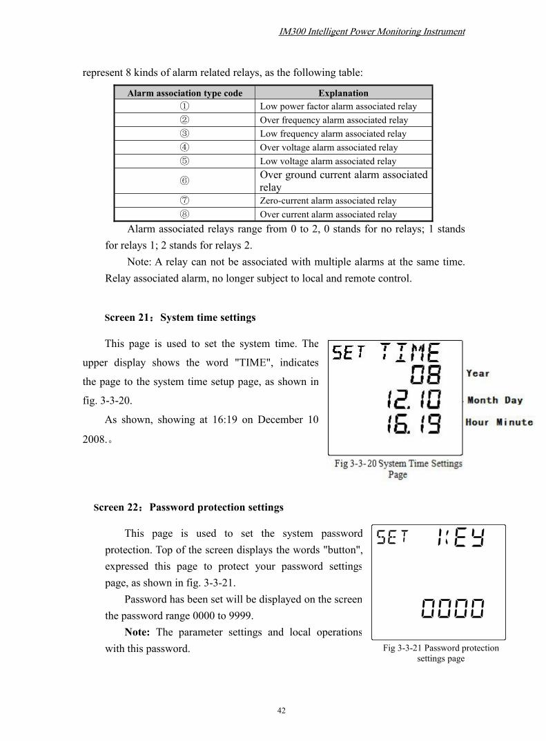
represent 8 kinds of alarm related relays, as the following table:
Alarm association type code Explanation① Low power factor alarm associated relay② Over frequency alarm associated relay③ Low frequency alarm associated relay④ Over voltage alarm associated relay⑤ Low voltage alarm associated relay
⑥Over ground current alarm associatedrelay
⑦ Zero-current alarm associated relay⑧ Over current alarm associated relay
Alarm associated relays range from 0 to 2, 0 stands for no relays; 1 standsfor relays 1; 2 stands for relays 2.
Note: A relay can not be associated with multiple alarms at the same time.Relay associated alarm, no longer subject to local and remote control.
Screen 21:System time settings
This page is used to set the system time. The
upper display shows the word "TIME", indicates
the page to the system time setup page, as shown in
fig. 3-3-20.
As shown, showing at 16:19 on December 10
2008.。
Screen 22:Password protection settings
This page is used to set the system passwordprotection. Top of the screen displays the words "button",expressed this page to protect your password settingspage, as shown in fig. 3-3-21.
Password has been set will be displayed on the screen,the password range 0000 to 9999.
Note: The parameter settings and local operationswith this password.

IM300 Intelligent Power Monitoring Instrument
43
Fig. 3-3-22 Rates setting page.
Fig 3-3-24 Setting the base valueof total reactive energy
Screen 23:Period rates setting 1
This page is used to set 00:00 ~ 06:00 of the period
rates. Top of the screen displays "ET-1" displayed, it
indicates this page to set the period rates 1, as shown in
fig. 3-3-22.
Each digit represents a step time (0.5 hours), the
display time period after activation, each number ranging
from 1 to 4, the representative rates in the following table:
Rate Type Code Explanation1 Sharp, Rates2 Peak Rates
3 Shoulder Rates4 Off-peak Rates
Screen 24:Period rates setting 2
This page is used to set 06:00 ~ 12:00 of the period rates. Top of the screen
displays "ET-2" words, similar methods of operation and the
display screen and the fourteenth.
Screen 25:Period rates setting 3
This page is used to set 12:00 ~ 18:00 of the period rates.
Top of the screen displays "ET-3" words, similar methods of
operation and the display screen and the fourteenth.
Screen 26:Period rates setting 4
This page is used to set the 18: 00 hours fee rates: 00 to 24.
Top of the screen displays "ET-4" words, similar methods of
operation and the display screen and the fourteenth.
Screen 27:Setting the base value of total active energy
This page is used to setting the base value of total active
Fig 3-3-23 Setting the basevalue of total active energy

IM300 Intelligent Power Monitoring Instrument
44
Fig 3-3-25 Setting the base value of
A-phase active energy
Fig 3-3-26 Setting the baseabsolute value of total forward
active energy
energy, as shown in fig. 3-3-23, top of the screen displays "EP" and "total" refers to
the total active energy, the base value is displayed at the bottom of the screen and the
range is from 0 to 99999999.9kWh.
Screen 28:Setting the base value of total reactive energy
This page is used to setting the base value of total reactive
energy, as shown in fig. 3-3-24, the top of the screen shows
"Eq" and "total" refers to the total reactive energy, the base
value is displayed at the bottom of the screen and the range is
from 0 to 99999999.9kvarh.
Screen 29: Setting the base value of A-phase active
energy
When wiring for the 3-phase 4-wire system, the page used
to setting the base value of A-phase energy, as shown in fig. 3-3-25, top of the screen
displays "EP", are setting the active energy, "a" represents the A-phase, the base
value is displayed at the bottom of the screen and the range is from 0 to 99999999.9.
Screen 30、31:Setting the base value of B/C-phase active energy
When wiring for the 3-phase 4-wire system, it was used to setting the base value
of B,C-phase active energy. "b" represents phase B, "c" represents a C-phase. Similar
methods of operation and the Twenty-screen display.
Screen 32~34:Setting the base value of A/B/C-phase
reactive energy
When wiring for the 3-phase 4-wire system, it is used to
setting the base value of A, B, C-phase reactive energy. The top
of the screen shows "Eq", bottom right of the screen displays

IM300 Intelligent Power Monitoring Instrument
45
"kvarh" expressed as reactive power, "a" represents the A-phase, "b" represents phase
B, "c" represents a C-phase. Similar methods of operation and the Twenty-screen
display.
Screen 35:Setting the base absolute value of total forward active energy
This page is used to setting the base absolute value of total forward active
energy . As shown in fig. 3-3-26: the top of the screen shows the "total" and "+ EP",
the base value is displayed at the bottom of the screen and the range is from 0 to
99999999.9kWh.
Screen 36:Setting the forward base value of total active energy at sharp rate
This page is used to setting the forward base value of total active energy at sharp
rate, similar to the methods of operation and the display screen with the twenty-sixth.
Screen 37~39:Setting the forward base value of total active energy at peak,
shoulder or off-peak rate
They are used to setting the forward base value of total active energy at peak,
shoulder, off-peak rates. Top of the screen displays "+ EP" type rate were similar peak,
shoulder, off-peak, methods of operation and the display screen and twenty-sixth.
Screen 40:Setting the base absolute value of total reverse active energy
This page is used to setting the base absolute value of total reverse active energy .
Top of the screen display similar to "-EP", methods of operation and the display
screen and twenty-sixth.
Screen 41~44 : Setting the reverse base value of total active energy at
sharp,peak, shoulder or off-peak rate
They are used to setting the reverse base value of total active energy at
sharp,peak, shoulder or off-peak rate. Top of the screen displays "-EP" rate type were
sharp,peak,shoulder, off-peak, methods of operation and display screen similar to the

IM300 Intelligent Power Monitoring Instrument
46
Fig 3-3-27 Setting the baseabsolute value of total forward
reactive energy
twenty-sixth.
Screen 45 : Setting the base absolute value of total
forward reactive energy
This page is used to setting the base absolute value of total
forward reactive energy. As shown in fig. 3-3-27: the top of the
screen shows the "total" and "+ Eq", the base value is displayed
at the bottom of the screen and the range is from 0 to
99999999.9kvarh.
Screen 46:Setting the forward base value of total reactive energy at sharp
rate
This page is used to setting the forward base value of total reactive energy at
sharp rate,methods of operation and the display screen similar to the thirty-sixth.
Screen 47~49:Setting the forward base value of total reactive energy at peak,
shoulder or off-peak rate
They are used to setting the forward base value of total reactive energy at peak,
shoulder or off-peak rates. Top of the screen displays "+ Eq" rate types are similar
peak, shoulder, off-peak, methods of operation and the screen displays thirty-sixth.
Screen 50:Setting the base absolute value of total reverse reactive energy
This page is used to setting the base absolute value of total reverse reactive
energy. Top of the screen display similar to "-Eq", methods of operation and the
screen displays thirty-sixth.
Screen 51~54:Setting the reverse base value of total reactive energy at
sharp,peak, shoulder or off-peak rate
IM300 Intelligent Power Monitoring Instrument
47
They are used to setting the reverse base value of total reactive energy at
sharp,peak, shoulder or off-peak rates. Top of the screen displays "-Eq" rate type were
sharp, peak, shoulder, off-peak, methods of operation and the display screen similar to
the thirty-sixth.
Screen 55:Setting the absolute base value of the 1th quadrant total reactive
energy
This page is used to setting the absolute base value of the 1th Quadrant total
reactive energy. The top of the screen shows "Eq-1", the bottom right of the screen
displays "kvarh" expressed as reactive power, methods of operation and the display
screen similar to the thirty-sixth.
Screen 56~59: Setting the base value of the 1th quadrant total reactive
energy at sharp,peak, shoulder or off-peak rate
They are used to setting the base value of the 1th quadrant total reactive energy
at sharp,peak, shoulder or off-peak rates. The top of the screen shows "Eq-1" rate type
are sharp, peak, shoulder, off-peak, the bottom right of the screen displays "kvarh"
expressed as reactive power, methods of operation and the display screen similar to
the thirty-sixth.
Screen 60:Setting the absolute base value of the 4th quadrant total reactive
energy
This page is used to setting the absolute base value of the 4th quadrant total
reactive energy. The top of the screen shows "Eq-4", bottom right of the screen
displays "kvarh" expressed as reactive power, methods of operation and the display
screen similar to the thirty-sixth.
Screen 61~64: Setting the base value of the 4th quadrant total reactive
energy at sharp,peak, shoulder or off-peak rate

IM300 Intelligent Power Monitoring Instrument
48
They are used to seting the base value of the 4th quadrant total reactive energy at
sharp,peak, shoulder or off-peak rates. The top of the screen shows "Eq-4" rate type
were sharp, peak, shoulder, off-peak, the bottom right of the screen displays "kvarh"
expressed as reactive power, methods of operation and the display screen similar to
the thirty-sixth.
Screen 65:Setting the absolute base value of the 2th quadrant total reactive
energy
This page is used to setting the absolute base value of the 2th quadrant total
reactive energy. The top of the screen shows "Eq-2", the bottom right of the screen
displays "kvarh" expressed as reactive power, methods of operation and the display
screen similar to the thirty-sixth.
Screen 56~69: Setting the base value of the 2th quadrant total reactive
energy at sharp,peak, shoulder or off-peak rate
They are used to setting the base value of the 2th quadrant total reactive energy
at sharp,peak, shoulder or off-peak rate. The top of the screen shows "Eq-2" rate type
were sharp, peak, shoulder, off-peak, the bottom right of the screen displays "kvarh"
expressed as reactive power, methods of operation and the display screen similar to
the thirty-sixth.
Screen 70:Setting the absolute base value of the 3th quadrant total reactive
energy
This page is used to seting the absolute base value of the 3th quadrant total
reactive energy. The top of the screen shows "Eq-3", the bottom right of the screen
displays "kvarh" expressed as reactive power, methods of operation and the display
screen similar to the thirty-sixth.
Screen 71~74: Setting the base value of the 3th quadrant total reactive

IM300 Intelligent Power Monitoring Instrument
49
energy at sharp,peak, shoulder or off-peak rate
They are used to setting the base value of the 3th quadrant total reactive energy
at sharp,peak, shoulder or off-peak rates. The top of the screen shows "Eq-3" type rate
were sharp, peak, shoulder, off-peak, the bottom right of the screen displays "kvarh"
expressed as reactive power, methods of operation and the display screen similar to
the thirty-sixth.
After completing all of the parameter settings, press button to return to the
first screen.
3.4. Local Operation
In the single button mode, you can enter the local operation mode by pressing“ ” and “ ” at the same time, “OPR” will display at the left top corner of thescreen.
Note: In the local operation mode, press “ ” and “ ” will exit and go back tothe single button mode. If you don't press “ ” to activate the page, press “ ”will turn to next screen. The screen will go back to the single button modeautomatically if there is no operation on buttons in ten minutes.
3.4.1. Local operation features
In local mode of operation can be performed:
Control the two relays output are opened or closed;
Clear SOE, clear power base, clear maximum demand;
Maximum electrical parameters of the minimum reset;
The alarm reset;
System reset operation.
3.4.2. Each local operation screen presentation
Starting interface for local operation mode password confirmation each time to
enter the local mode of operation are first prompted for a password, the password is
displayed as "----." Password total of four, ranging from 0000 to 9999, the factory
default value "0000." To enhance the confidentiality, is only display digital digit

IM300 Intelligent Power Monitoring Instrument
50
Fig 3-4-2 The first relayoperation
Fig 3-4-3 Relay actionconfirmation
Fig 3-4-4 Relay operation failed
password set, the other bits are displayed as "-." After the input is complete press
button to confirm, if you enter the correct password is entered the local operation of
the first screen, otherwise stay on this page.
Screen 1: Output operation of relay 1
This page is used to control the on-off status of relay 1. The
top of the screen shown in fig. 3-4-2 displays the word "OUT",
expressed as output operation of relay 1 , the middle of the screen
displays "1" indicating that the relay 1.
Relay status after Press buttons "OP" blinking, press
the button or bond can be "OP" or "CL" option. "OP"
that is "OPEN" indicates relay operation points, "CL" ie "CLOSE"
indicates relay closing operation.
Note: When the relay output is set to pulse output, you can
not select "OP", can only choose to "CL".
After selecting relay status, press button appears to
confirm whether or not the current operation prompts, as shown in
fig. 3-4-3. "Y" on behalf of YES, confirms that the local operation,
"N" on behalf of NO, that is, no local operation. Press button
to make "Y" or "N" option, press button.
Select "N" press button to confirm, the relay does not
operate. Select Y press button is not immediately operate the
relay, but first check the current status of the relay: If the relay is
currently not operating, then the relay will be operated; current
relay under operation, the relay will not operate while the top of
the screen display "ERR" word indicates that the operation failed,
as shown in fig. 3-4-4. Now press button will turn to the next
screen; press button to reset the relay status.
Screen 2:Output operation of relay 2
This page is used to control the on-off status of relay 2. The middle of the screen

IM300 Intelligent Power Monitoring Instrument
51
Fig 3-4-7 Clear the accumulatedvalue of electricity measurement
Fig 3-4-5 Clear SOE of switchingvalue
Fig 3-4-6 Confirm theremoval of SOE
shows "2", means the relay 2.
Operation method of relay 2 and the relay 1 is exactly the same, please refer to
the operation method of relay 1.
Screen 3:Clear SOE of switching value
This page is used to clear SOE record of switching value. As
shown in fig. 3-4-5, "CLR a" is shown in the upper left corner,
and "SOE" is displayed at the top of the screen.
If you do not want to clear the , press the SOE button
will skip this screen; if you want to clear, please press the
button, the screen becomes as shown in fig. 3-4-6. Select the "Y"
that is YES, to confirm the removal of SOE, select "N" that is NO,
not clear SOE.
Screen 4:Clear SOE of the overlimit alarm
This page is used to clear SOE record of the overlimit alarm. The upper left
corner of the screen displays "CLR b". The word "SOE" is
displayed at the top of the screen, indicating that the overlimit
alarm SOE is cleared. Operation method and display similar to
the third screen
Screen 5:Clear the accumulated value of electricity
measurement
This page is used to clear the accumulated value of
electricity measurement. As shown in fig. 3-4-7, the upper left corner of the screen
displays "CLR" (CLEAR) means clear, the top of the screen displays "ENGY"
(ENGERY) means clear the electric base, The operation to clear the accumulated
value of electricity is the same as clearing the SOE.
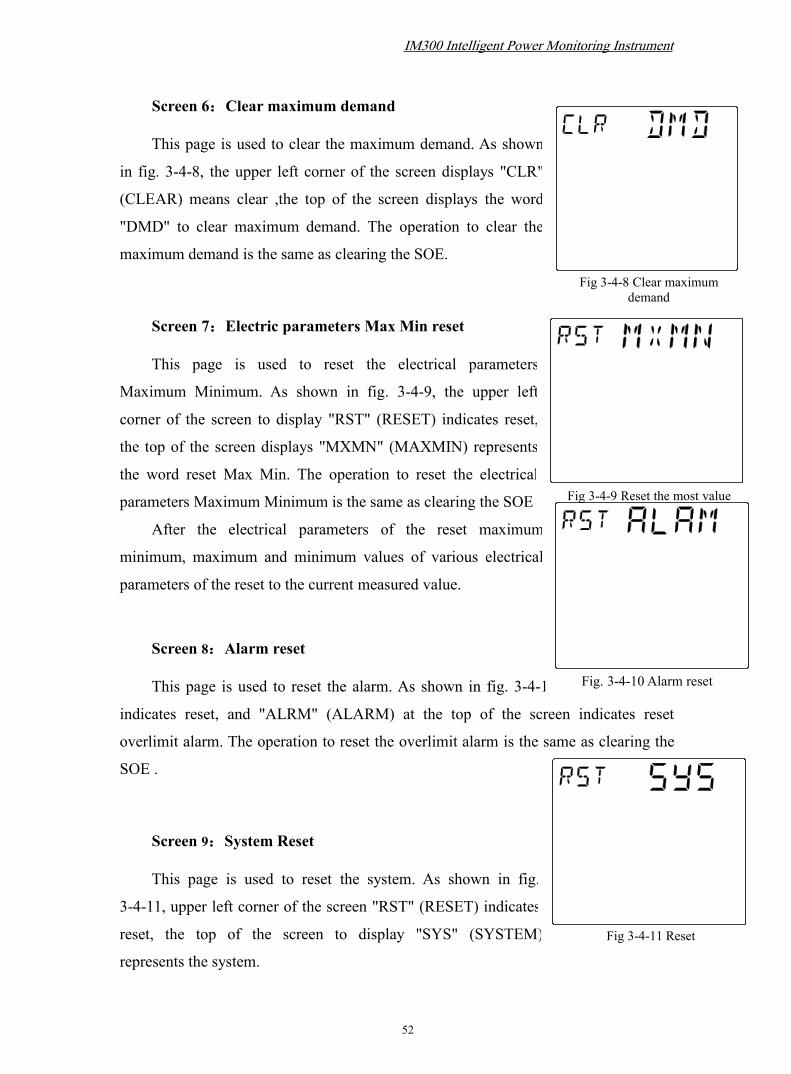
IM300 Intelligent Power Monitoring Instrument
52
Fig 3-4-9 Reset the most value
Fig 3-4-8 Clear maximumdemand
Fig 3-4-11 Reset
Screen 6:Clear maximum demand
This page is used to clear the maximum demand. As shown
in fig. 3-4-8, the upper left corner of the screen displays "CLR"
(CLEAR) means clear ,the top of the screen displays the word
"DMD" to clear maximum demand. The operation to clear the
maximum demand is the same as clearing the SOE.
Screen 7:Electric parameters Max Min reset
This page is used to reset the electrical parameters
Maximum Minimum. As shown in fig. 3-4-9, the upper left
corner of the screen to display "RST" (RESET) indicates reset,
the top of the screen displays "MXMN" (MAXMIN) represents
the word reset Max Min. The operation to reset the electrical
parameters Maximum Minimum is the same as clearing the SOE
After the electrical parameters of the reset maximum
minimum, maximum and minimum values of various electrical
parameters of the reset to the current measured value.
Screen 8:Alarm reset
This page is used to reset the alarm. As shown in fig. 3-4-10, "RST" (RESET)
indicates reset, and "ALRM" (ALARM) at the top of the screen indicates reset
overlimit alarm. The operation to reset the overlimit alarm is the same as clearing the
SOE .
Screen 9:System Reset
This page is used to reset the system. As shown in fig.
3-4-11, upper left corner of the screen "RST" (RESET) indicates
reset, the top of the screen to display "SYS" (SYSTEM)
represents the system.
Fig. 3-4-10 Alarm reset

IM300 Intelligent Power Monitoring Instrument
53
The operation to system reset is the same as clearing SOE.
3.5. SOE and statistic Inquiry3.5.1. Features
In the single button mode, press and button to enter into the event log
query mode, the upper left corner of the screen displays the word "SOE a", indicates
the switch event log. Press or button up and down to view content. Press
“ ” will turn screen directly, The limit alam SOE "SOE b", the maximum minimum
value of the electrical parameter, and the maximum demand "DMD" in turn.
Note: The screen will go back to the single button mode automatically if there isno operation on buttons in ten minutes.
3.5.2. Inquiry switching value SOE
If there is no SOE records in RAM, after entering inquiry SOE mode, the upper
display shows "NO", as shown in fig. 3-5-1. If there is SOE records in RAM,The " "
sign is displayed in the lower left corner of the screen.After entering inquiry SOE
mode, as shown in fig. 3-5-2:
① Total switch SOE event (up to 32). As shown there are currently a total of
16 events are recorded.
② Current event being viewed. As shown currently are visiting for the third
events.
③ Types of events: in the following table.
Fig 3-5-2 SOE record1 2 3 4
5
Fig 3-5-1 No SOE record

IM300 Intelligent Power Monitoring Instrument
54
Type Number Type Description1 Switching value input 1 shift event2 Switching value input 2 shift event3 Switching value input 3 shift event4 Switching value input 4 shift event
④ Status of event. 0: “on” to “off” ; 1: “off” to “on”.
⑤ The time of the event occur.See in fig 3-5-2: the time of the event occurs
is 2007-11-27 13:21:59 253ms
If you have multiple SOE events, press or buttons to page up and
down buttons to view.
Note: If all SOE events have been uploaded via communication or all SOE
events in memory have been cleared through local operations, the " "
mark in the lower left corner of the screen will disappear.
3.5.3. Inquiry the limit alarm SOE OperationIf there is no limit alarm SOE record in RAM, after entering the inquiry SOE
mode, the "NO" is displayed on the top of the screen, as shown in fig. 3-5-3. If there
is limit alarmSOE record in RAM, after entering the inquiry SOE mode, as shown in
fig. 3-5-4.
① The total number of limit alarm SOE events (the maximum is 16).There are
8 recorded events in the picture.
1 2 3 4
5
Fig 3-5-4 SOE eventsFig 3-5-3 No SOE events

IM300 Intelligent Power Monitoring Instrument
55
Fig 3-5-5 Maximum value ofphase voltage
② The sequence number of the current events.As pictured currently is the third
event.
③ Type of the event:
Type NO. Description
OC Over-current alarm
LC Zero-current alarm
ET Over ground current alarm
OU Over voltage alarm
LU Low voltage alarm
OF Over frequency alarm
LF Low frequency alarm
PF Low power factor alarm
④ Phase of event: “a” denotes phase A, “b” denotes phase B, “c” denotes phase
C.
⑤ The time of the event occur.
See in fig 3.5.3.2: the time of the event occurs is 2007-11-27 13:21:59 253msYou can view all the SOE events pressing “ ” or “ ”.
3.5.4. Inquiry the electrical parameters of maximum and minimum operating
presentation
After entering the electrical parameters of the maximum and minimum mode,
press or button to page up and down to view; press button to view
the value of a electrical parameter and the time of occurrence, minimum and
maximum occurrence time are flashing several second. The time display mode is
“year-month-day” and “hour: minute: second” alternating
displayed. The current statistical data viewed are all from
last statistical interval.
Screen 1:Maximum value of phase voltage
The screen shows a maximum value of 3-phase

IM300 Intelligent Power Monitoring Instrument
56
Fig 3-5-6Minimum value ofphase voltage
voltage, as 3-5-5: the upper left corner of the screen displays "U_max", represents
the maximum voltage, 'a', 'b', 'c', respectively, A-phase, B-phase, C-phase voltage,
unit is V or kV. Occurrence time of the maximum value is displayed at the bottom
of the screen.
Note: The only show in the 3-phase 4-wire page.
Screen 2:Minimum value of phase voltage
The screen displays the minimum value of the
3-phase voltage, as shown in fig. 3-5-6: the upper left
corner of the screen displays "U_min", represents the
minimum voltage, 'a', 'b', 'c', respectively, A-phase,
B-phase, C-phase voltage,unit is V or kV. Occurrence
time of the minimum value is displayed at the bottom
of the screen.
Note: The only show in the 3-phase 4-wire page.
Screen 3:Maximum value of line to line voltage
The screen displays the maximum value of line to line voltage, the upper left
corner of the screen displays "U_max", represents the maximum value of line to line
voltage, 'ab', 'bc', 'ca' denote the line voltage AB, BC, CA, with the first screen display
similar .
Screen 4:Minimum value of line to line voltage
The screen displays the minimum value of line to line voltage, upper left corner
of the screen displays "U_min", represents the minimum value of line to line voltage,
'ab', 'bc', 'ca' denote the line voltage AB, BC, CA, with a second similar screen
display .
Screen 5:Maximum value of current

IM300 Intelligent Power Monitoring Instrument
57
The screen shows the maximum value of current, the upper left corner of the
screen displays "I_max", represents the maximum value of current, 'a', 'b', 'c', 'n'
denote the A-phase, B-phase, C-phase, zero-sequence current ,unit is A. Similar to the
first display screen.
Screen 6:Minimum value of current
The screen displays the minimum value of current,, the upper left corner of the
screen displays "I_min", represents the minimum value of current, 'a', 'b', 'c', 'n' denote
the A-phase, B-phase, C-phase, zero-sequence current,unit is A. Similar to the second
display screen.
Screen 7:Maximum value of power factor
The screen displays the maximum value of power factor, upper left corner of
the screen displays the word "PF_max", represents the maximum value of the
power factor, 'a', 'b', 'c', '', respectively, A-phase, B-phase, C-phase, total power
factor, showed similar with the first screen.
Note: Do not display the A-phase ,B-phase, C-phase maximum value of
power factor in the 3-phase 3-wire system,it displays the maximum value of total
power factor only in the first row.
Screen 8:Minimum value of power factor
The screen displays the minimum value of power factor, the upper left corner
of the screen displays the word "PF_min", indicates the minimum value of power
factor, 'a', 'b', 'c', '', respectively, A-phase, B-phase, C-phase, the total power factor,
with a second similar display screen.
Note: Do not display the A-phase ,B-phase, C-phase maximum value of
power factor in the 3-phase 3-wire system,it displays the minimum value of total
power factor only in the first row.
Screen 9:Maximum value of total power and frequency

IM300 Intelligent Power Monitoring Instrument
58
The screen displays the maximum value of total power and frequency, and the
upper left corner of the screen displays the word "P_ max", representsmaximum value
of total power and frequency, 'Σ' represents the total power, the first three rows are
active power, reactive power, apparent power, units are kW, kvar, kVA. The fourth
row is frequency, unit is Hz. Occurrence time of the maximum value is displayed at
the bottom of the screen.
Screen 10:Minimum value of total power and frequency
The screen displays the minimum value of total power and frequency, top left
corner of the screendisplay the word "P_ min", representsthe minimum value of total
power and frequency, with a ninth screen display similar.
Screen 11:Maximum value of A-phase power
The screen displays the maximum value of A-phase power, the upper left corner
of the screen displays the word "Pa_ max", represents the maximum value of the
A-phase power, 'Σ' represents the total power, the first three rows are active power,
reactive power, apparent power, unit is kW, kvar, kVA. Occurrence time of the
maximum value is displayed at the bottom of the screen.
Note: This screen displayed in the 3-phase 4-wire system only.
Screen 12:Minimum value of A-phase power
The screen displays the minimum value of A-phase power,, top left corner of
the screen displays the word "Pa_min", indicates the minimum value of A-phase
power,, with an eleventh screen display similar.
Note: This screen displayed in the 3-phase 4-wire system only.
Screen 13:Maximum value of B-phase power
The screen displays the maximum value of B-phase power, the upper left
corner of the screen displays the word "Pb_ max", represents the maximum value
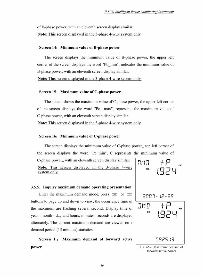
IM300 Intelligent Power Monitoring Instrument
59
Fig.3-5-7 Maximum demand offorward active power
of B-phase power, with an eleventh screen display similar.
Note: This screen displayed in the 3-phase 4-wire system only.
Screen 14:Minimum value of B-phase power
The screen displays the minimum value of B-phase power, the upper left
corner of the screen displays the word "Pb_min", indicates the minimum value of
B-phase power, with an eleventh screen display similar.
Note: This screen displayed in the 3-phase 4-wire system only.
Screen 15:Maximum value of C-phase power
The screen shows the maximum value of C-phase power, the upper left corner
of the screen displays the word "Pc_ max", represents the maximum value of
C-phase power, with an eleventh screen display similar.
Note: This screen displayed in the 3-phase 4-wire system only.
Screen 16:Minimum value of C-phase power
The screen displays the minimum value of C-phase power,, top left corner of
the screen displays the word "Pc_min", C represents the minimum value of
C-phase power,, with an eleventh screen display similar.
Note: This screen displayed in the 3-phase 4-wiresystem only.
3.5.5. Inquiry maximum demand operating presentation
Enter the maximum demand mode, press or
buttons to page up and down to view; the occurrence time of
the maximum are flashing several second. Display time of
year - month - day and hours: minutes: seconds are displayed
alternately. The current maximum demand are viewed on a
demand period (15 minutes) statistics.
Screen 1 : Maximum demand of forward active
power
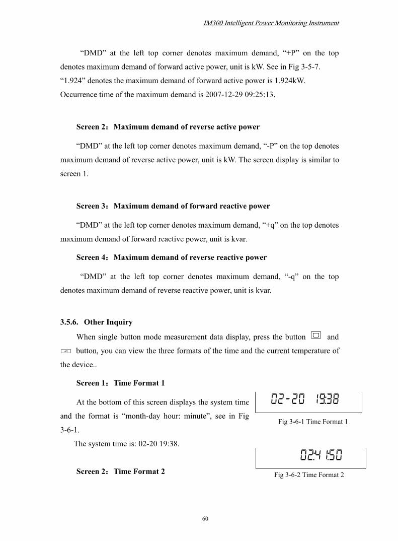
IM300 Intelligent Power Monitoring Instrument
60
Fig 3-6-1 Time Format 1
Fig 3-6-2 Time Format 2
“DMD” at the left top corner denotes maximum demand, “+P” on the top
denotes maximum demand of forward active power, unit is kW. See in Fig 3-5-7.
“1.924” denotes the maximum demand of forward active power is 1.924kW.
Occurrence time of the maximum demand is 2007-12-29 09:25:13.
Screen 2:Maximum demand of reverse active power
“DMD” at the left top corner denotes maximum demand, “-P” on the top denotes
maximum demand of reverse active power, unit is kW. The screen display is similar to
screen 1.
Screen 3:Maximum demand of forward reactive power
“DMD” at the left top corner denotes maximum demand, “+q” on the top denotes
maximum demand of forward reactive power, unit is kvar.
Screen 4:Maximum demand of reverse reactive power
“DMD” at the left top corner denotes maximum demand, “-q” on the top
denotes maximum demand of reverse reactive power, unit is kvar.
3.5.6. Other Inquiry
When single button mode measurement data display, press the button and
button, you can view the three formats of the time and the current temperature of
the device..
Screen 1:Time Format 1
At the bottom of this screen displays the system time
and the format is “month-day hour: minute”, see in Fig
3-6-1.
The system time is: 02-20 19:38.
Screen 2:Time Format 2

IM300 Intelligent Power Monitoring Instrument
61
Fig 3-6-4 Time Format 3
Fig 3-6-3 Device temperature
At the bottom of this screen displays the system time and the format is “hour:
minute: second”, see in Fig 3-6-2.
The system time is: 02: 41: 50..
Screen 3:Temperature of device
At the bottom of this screen displays the
temperature of device, see in Fig 3-6-3.
The temperature of device is: 25.8℃
Screen 4:Time Format 3
At the bottom of this screen displays the system time
and the format is “year: month: day”, see in Fig 3-6-4.
The system time is: 2008-02-20.
Screen 5:No display
At the bottom of this screen displays nothing.
4. Communication
4.1. MODBUS protocol overviewMODBUS-RTU communication protocol is more commonly used as a
communication protocol, the response from the main station and the slave station
connection (half duplex). Themain station (for example PC) send a command to all
the terminal devices (for example IM300), The addressed terminal device sends a
response signal to the host.
4.1.1 The transmission format
Information is transmitted asynchronously and in bytes. The communication
message passing between the main station and the slave station is the 11-bit word
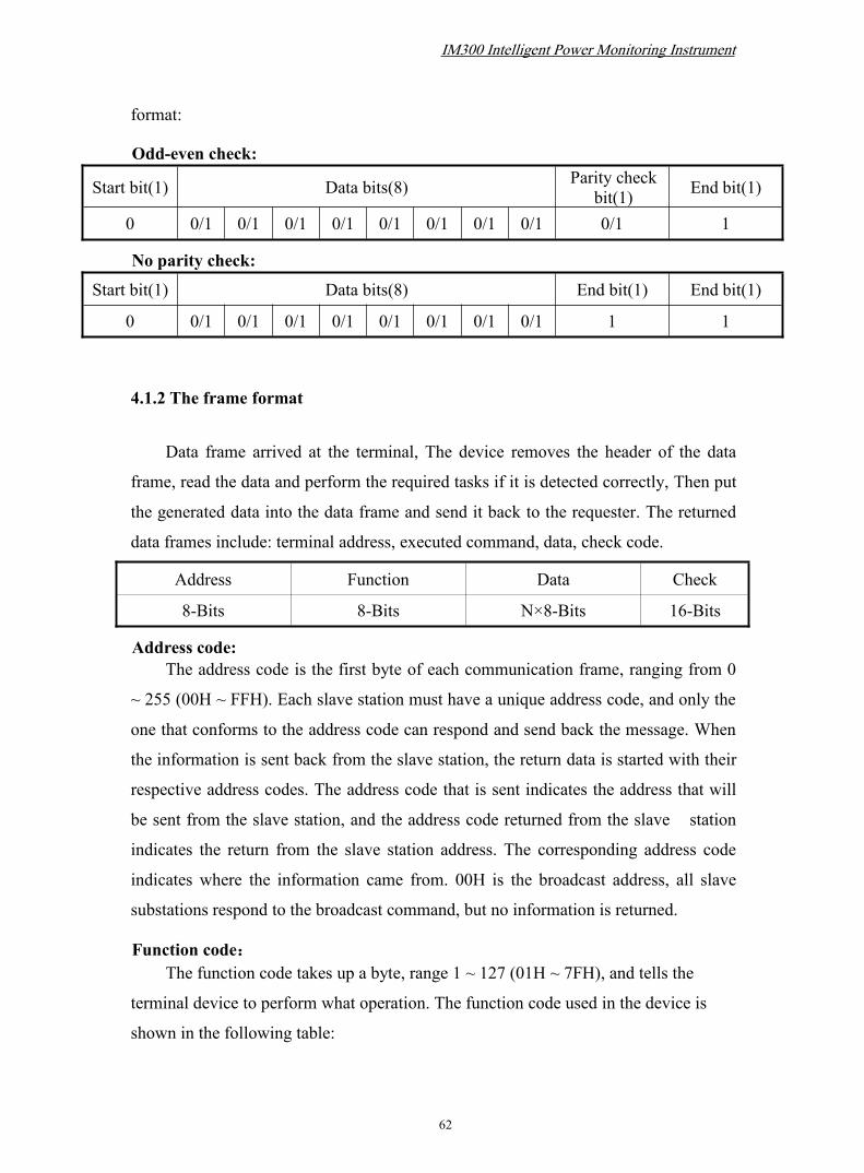
IM300 Intelligent Power Monitoring Instrument
62
format:
Odd-even check:
Start bit(1) Data bits(8) Parity checkbit(1) End bit(1)
0 0/1 0/1 0/1 0/1 0/1 0/1 0/1 0/1 0/1 1
No parity check:
Start bit(1) Data bits(8) End bit(1) End bit(1)
0 0/1 0/1 0/1 0/1 0/1 0/1 0/1 0/1 1 1
4.1.2 The frame format
Data frame arrived at the terminal, The device removes the header of the data
frame, read the data and perform the required tasks if it is detected correctly, Then put
the generated data into the data frame and send it back to the requester. The returned
data frames include: terminal address, executed command, data, check code.
Address Function Data Check
8-Bits 8-Bits N×8-Bits 16-Bits
Address code:The address code is the first byte of each communication frame, ranging from 0
~ 255 (00H ~ FFH). Each slave station must have a unique address code, and only the
one that conforms to the address code can respond and send back the message. When
the information is sent back from the slave station, the return data is started with their
respective address codes. The address code that is sent indicates the address that will
be sent from the slave station, and the address code returned from the slave station
indicates the return from the slave station address. The corresponding address code
indicates where the information came from. 00H is the broadcast address, all slave
substations respond to the broadcast command, but no information is returned.
Function code:The function code takes up a byte, range 1 ~ 127 (01H ~ 7FH), and tells the
terminal device to perform what operation. The function code used in the device is
shown in the following table:
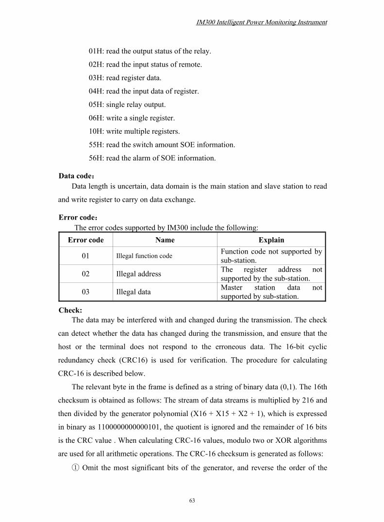
IM300 Intelligent Power Monitoring Instrument
63
01H: read the output status of the relay.
02H: read the input status of remote.
03H: read register data.
04H: read the input data of register.
05H: single relay output.
06H: write a single register.
10H: write multiple registers.
55H: read the switch amount SOE information.
56H: read the alarm of SOE information.
Data code:Data length is uncertain, data domain is the main station and slave station to read
and write register to carry on data exchange.
Error code:The error codes supported by IM300 include the following:
Error code Name Explain
01 Illegal function code Function code not supported bysub-station.
02 Illegal address The register address notsupported by the sub-station.
03 Illegal data Master station data notsupported by sub-station.
Check:The data may be interfered with and changed during the transmission. The check
can detect whether the data has changed during the transmission, and ensure that the
host or the terminal does not respond to the erroneous data. The 16-bit cyclic
redundancy check (CRC16) is used for verification. The procedure for calculating
CRC-16 is described below.
The relevant byte in the frame is defined as a string of binary data (0,1). The 16th
checksum is obtained as follows: The stream of data streams is multiplied by 216 and
then divided by the generator polynomial (X16 + X15 + X2 + 1), which is expressed
in binary as 1100000000000101, the quotient is ignored and the remainder of 16 bits
is the CRC value . When calculating CRC-16 values, modulo two or XOR algorithms
are used for all arithmetic operations. The CRC-16 checksum is generated as follows:
① Omit the most significant bits of the generator, and reverse the order of the

IM300 Intelligent Power Monitoring Instrument
64
bits. Form a new polynomial, the result is 1010000000000001 or hexadecimal A001.
② Load all 1s or hexadecimal FFFFs into 16-bit registers.
③ 16-bit register with low-order byte of the first data byte XOR operation, the
results stored in 16-bit register.
④ 16-bit register to the right one. If the overflow bit is 1, go to step 5, otherwise
go to step 6.
⑤ MOR operation is performed on the 16-bit register with the new generator
polynomial and the result is stored in the 16-bit register.
⑥ Repeat step 4 until it is shifted 8 times.
⑦ XOR operation of the next data byte with the low byte of the 16-bit register,
the result is stored in a 16-bit register.
⑧ Repeat steps 4 to 7 until all bytes of data have been XORed with 16-bit
registers.
⑨ 16-bit register is the content of CRC-16.
4.2. Communication protocol address table and description
Relay operation address table, supports read function of code 01 and remotecontrol function of code 05
Address Type Name Register
00010 RW RL1 1
00011 RW RL2 1
Digital address table, supports read function of code 02
Address Type Name Register
10100 RO DI1 1
10101 RO DI2 1
10102 RO DI3 1
10103 RO DI4 1
System information address table, supports read function of code 03,04 andset the code 06,10

IM300 Intelligent Power Monitoring Instrument
65
Address Type Name Ranges Remark Register
40010 RO ASCII code indicates thehardware version number 1
40011 RO ASCII code indicates thesoftware version number 1
40012 RO ASCII code indicates year 140013~40015 RO ASCII code indicates the
product sequence number 3
40020 RW Systemtime××Year××Month Only support
all writtenandbroadcastall written
1
40021 RW Systemtime××Day××Hour 1
40022 RW Systemtime××Minute××Second 1
40023 RW System time××Millisecond 1
40030 RW Communication address 1~254 Defaults :254 1
40032 RW Communication baud rate 1~5 Defaults:4 1
40034 RW Communication check mode 0~3 Defaults:0 1
40050 RO Sub-station status 1
40055 WO Sub-station setting 1
40060 RO Freeze/Thaw state of energy 1
System parameter address table, supports read function of code 03,04 andset the code 06,10
Address Type Name Ranges Remark Register
40062 RW The selection of systemfrequency 5000/6000 1

IM300 Intelligent Power Monitoring Instrument
66
40065 RW
Electrical parameters ofthe maximum andminimum range ofstatistics
1~1440min Defaults:10 1
40067 RW Direction of CT wiring Defaults :0x00000000
2(Writecontinuously)
40070 RW Telemetry wiring mode 1~5 Defaults:1 1
40072 RW PT primary voltagerating 100~35000V Defaults:
220/220
2(Writecontinuously)40073 RW PT secondary voltage
rating 100~220V
40075 RW
bit14-bit0 represents CTprimary current ratingbit15 = 0/1 indicates thesecondary is 5A/1A
Primarycurrentrating:1~9999A
Defaults:0x1388(5000:5)
1
40077 RW
bit 14-bit 0 indicateszero-sequence CTprimary current ratingbit15 = 0/1 indicates thesecondary is 5A /1A
Primarycurrentrating:1~9999A
Defaults:0x1388(5000:5)
1
40081 RW Relay output settings 1~2 Defaults:1 1
40085 AO related electricalparameter range 2(Write
continuously)40086 AO related electrical
parameter types
40088 RW Pulse length of relayoutput 50~20000
Defaults :
2000,Unit:ms
1

IM300 Intelligent Power Monitoring Instrument
67
40090 RW back-light time 0~30 minutes Defaults:5 1
40092~40097 RW
Time-sharingaccounting settings(4rates 48 periods))
Stepper: 0.5hours Defaults:0xaa
6(Writecontinuously)
Basic electric parameter address table, supports read function of code 03, 04
Address Type Name Register
40100 RO Lin voltage Uab 1
40101 RO Line voltage Ubc 1
40102 RO Line voltage Uca 1
40103 RO Average value of line voltage ULLAvg 1
40104 RO Phase voltage Uan 1
40105 RO Phase voltage Ubn 1
40106 RO Phase voltage Ucn 1
40107 RO Average value of phase voltage ULN Avg 1
40108 RO Current Ia 1
40109 RO Current Ib 1
40110 RO Current Ic 1
40111 RO Average of 3-phase current I Avg 1
40112 RO Zero-sequence current In 1
40113 RO Total frequency (F) 1
40115 RO Total power factor (PF) 1
40116 RO Total active power (W) 1
40117 RO Total reactive power (Q) 1
40118 RO Total apparent power (S) 1
40119 RO Power factor of phase A(PFa) 1
40120 RO Power factor of phase B(PFb) 1
40121 RO Power factor of phase C(PFc) 1
40122 RO Active power of phase A(Wa) 1

IM300 Intelligent Power Monitoring Instrument
68
40123 RO Active power of phase B(Wb) 1
40124 RO Active power of phase C(Wc) 1
40125 RO Reactive power of phase A(Qa) 1
40126 RO Reactive power of phase B(Qb) 1
40127 RO Reactive power of phase C(Qc) 1
40128 RO Apparent power of Phase A(Sa) 1
40129 RO Apparent power of phase B(Sb) 1
40130 RO Apparent power of phase C(Sc) 1
Note 1: In the 3-phase 3-wire system, the data in 40104 ~ 40107 and
40119~40130 are invalid and value is 0.
Note 2: The correspondence between the above data (Ai) and the actual
value is:
Voltage: U = (Ai / 10) × (PT1 / PT2), Ai is an unsigned integer, unitV.
Current: I = (Ai / 1000) × (CT1 / CT2), Ai is an unsigned integer,
unit:A.
Zero-sequence current: In = (Ai / 1000) × (CT01 / CT02), Ai is an
unsigned integer, unit:A.
Active power: P = Ai × (PT1 / PT2) × (CT1 / CT2), Ai signed integers,
unit:W.
Reactive power: Q = Ai × (PT1 / PT2) × (CT1 / CT2), Ai signed
integers, unit:var.
Apparent power: S = Ai × (PT1 / PT2) × (CT1 / CT2), Ai is an
unsigned integer, unit:VA.
Power factor: PF = Ai / 1000, Ai denote signed integers, no unit.
Frequency: F = Ai / 100, Ai as an unsigned integer, unit:Hz.
energy address table, supports read function of codes 03, 04 and set functionof code 10.Only support writes continuously
Address Type Data Definition Register
40200 RW The absolute value of total active energy 2

IM300 Intelligent Power Monitoring Instrument
69
40202 RW The absolute value of total reactive energy 2
40204 RW The absolute value of phase A active energy 2
40206 RW The absolute value of phase B active energy 2
40208 RW The absolute value of phase C active energy 2
40210 RW The absolute value of phase A reactive energy 2
40212 RW The absolute value of phase B reactive energy 2
40214 RW The absolute value of phase C reactive energy 2
40216 RW The forward value of total active energy 2
40218 RW The forward value of total active energy at sharp rate 2
40220 RW The forward value of total active energy at peak rate 2
40222 RW The forward value of total active energy at shoulder rate 2
40224 RW The forward value of total active energy at off-peak rate 2
40226 RW The reverse value of total active energy 2
40228 RW The reverse value of total active energy at sharp rate 2
40230 RW The reverse value of total active energy at peak rate 2
40232 RW The reverse value of total active energy at shoulder rate 2
40234 RW The reverse value of total active energy at off-peak rate 2
40236 RW The forward value of total reactive energy 2
40238 RW The forward value of total reactive energy at sharp rate 2
40240 RW The forward value of total reactive energy at peak rate 2
40242 RW The forward value of total reactive energy at shoulder rate 2
40244 RW The forward value of total reactive energy at off-peak rate 2
40246 RW The reverse value of total reactive energy 2
40248 RW The reverse value of total reactive energy at sharp rate 2
40250 RW The reverse value of total reactive energy at peak rate 2
40252 RW The reverse value of total reactive energy at shoulder rate 2
40254 RW The reverse value of total reactive energy at off-peak rate 2
40256 RW The absolute value of theⅠquadrant total reactive energy 2
40258 RW The absolute value of theⅠquadrant total reactive energy atsharp rate 2
40260 RW The absolute value of theⅠquadrant total reactive energy at 2

IM300 Intelligent Power Monitoring Instrument
70
peak rate
40262 RW The absolute value of theⅠquadrant total reactive energy atshoulder rate 2
40264 RW The absolute value of theⅠquadrant total reactive energy atoff-peak rate 2
40266 RW The absolute value of the IV quadrant total reactive energy 2
40268 RW The absolute value of the IV quadrant total reactive energyat sharp rate 2
40270 RW The absolute value of the IV quadrant total reactive energyat peak rate 2
40272 RW The absolute value of the IV quadrant total reactive energyat shoulder rate 2
40274 RW The absolute value of the IV quadrant total reactive energyat off-peak rate 2
40276 RW The absolute value of the II quadrant total reactive energy 2
40278 RW The absolute value of the II quadrant total reactive energy atsharp rate 2
40280 RW The absolute value of the II quadrant total reactive energy atpeak rate 2
40282 RW The absolute value of the II quadrant total reactive energy atshoulder rate 2
40284 RW The absolute value of the II quadrant total reactive energy atoff-peak rate 2
40286 RW The absolute value of the III quadrant total reactive energy 2
40288 RW The absolute value of the III quadrant total reactive energyat sharp rate 2
40290 RW The absolute value of the III quadrant total reactive energyat peak rate 2
40292 RW The absolute value of the III quadrant total reactive energyat shoulder rate 2
40294 RW The absolute value of the III quadrant total reactive energyat off-peak rate 2
Note 1: In the 3-phase 3-wire system, the data in 40204~40215 are
invalid and value is 0.
Note 2: The correspondence between the above data (Ai) and the
actual value is:
Active energy:: Ep=Ai/10,Ai denote unsigned long integer(0 ~
999,999,999),unit is KWh
Reactive energy:: Eq=Ai/10,Ai denote unsigned long integer(0 ~

IM300 Intelligent Power Monitoring Instrument
71
999,999,999),unit is kvarhNote 3: when set at the bottom, you need to set the total branch
amount and the total amount of electricity.
Note 4: When there is no multi-rate function, if you want to set the
base number of four-quadrant energy, you still need to write 10
registers at a time, and the settings of the sharp, peak, shouder, and
off-peak energy values are invalid.
Harmonic statistics (Harmonic distortion ratio/2-15th harmonic occupancy)address table, supports read function of codes 03, 04
Address Type Data Definition Register
40300 RO Total harmonic distortion ratio(THD)of A-phase (Uab)voltage 1
40301 RO Total harmonic distortion ratio(THD)of B-phase (Ubc)voltage 1
40302 RO Total harmonic distortion ratio(THD)of C-phase (Uca)voltage 1
40303 RO Total harmonic distortion ratio of current Ia 1
40304 RO Total harmonic distortion ratio of current Ib 1
40305 RO Total harmonic distortion ratio of current Ic 1
40306 RO Total harmonic distortion ratio of zero-sequence currentIn 1
40308 RO Odd harmonic distortion ratio of A-phase (Uab) voltage 1
40309 RO Odd harmonic distortion ratio of B-phase (Ubc) voltage 1
40310 RO Odd harmonic distortion ratio of C-phase (Uca) voltage 1
40311 RO Odd harmonic distortion ratio of current Ia 1
40312 RO Odd harmonic distortion ratio of current Ib 1
40313 RO Odd harmonic distortion ratio of current Ic 1
40314 RO Odd harmonic distortion ratio of zero-sequence current In 1
40315 RO Even harmonic distortion ratio of A-phase (Uab) voltage 1
40316 RO Even harmonic distortion ratio of B-phase (Ubc) voltage 1
40317 RO Even harmonic distortion ratio of C-phase (Uca) voltage 1

IM300 Intelligent Power Monitoring Instrument
72
40318 RO Even harmonic distortion ratio of current Ia 1
40319 RO Even harmonic distortion ratio of current Ib 1
40320 RO Even harmonic distortion ratio of current Ic 1
40321 RO Even harmonic distortion ratio of zero-sequence currentIn 1
40329 RO The 2nd harmonic ratio of phase A (Uab)voltage 1
40330 RO The 3rd harmonic ratio of phase A (Uab)voltage 1
40331 RO The 4th harmonic ratio of phase A (Uab)voltage 1
40332 RO The 5th harmonic ratio of phase A (Uab)voltage 1
40333 RO The 6th harmonic ratio of phase A (Uab)voltage 1
40334 RO The 7th harmonic ratio of phase A (Uab)voltage 1
40335 RO The 8th harmonic ratio of phase A (Uab)voltage 1
40336 RO The 9th harmonic ratio of phase A (Uab)voltage 1
40337 RO The 10th harmonic ratio of phase A (Uab)voltage 1
40338 RO The 11th harmonic ratio of phase A (Uab)voltage 1
40339 RO The 12th harmonic ratio of phase A (Uab)voltage 1
40340 RO The 13th harmonic ratio of phase A (Uab)voltage 1
40341 RO The 14th harmonic ratio of phase A (Uab)voltage 1
40342 RO The 15th harmonic ratio of phase A (Uab)voltage 1
40344 RO The 2nd harmonic ratio of phase B (Ubc)voltage 1
40345 RO The 3rd harmonic ratio of phase B (Ubc)voltage 1
40346 RO The 4th harmonic ratio of phase B (Ubc)voltage 1
40347 RO The 5th harmonic ratio of phase B (Ubc)voltage 1
40348 RO The 6th harmonic ratio of phase B (Ubc)voltage 1
40349 RO The 7th harmonic ratio of phase B (Ubc)voltage 1
40350 RO The 8th harmonic ratio of phase B (Ubc)voltage 1
40351 RO The 9th harmonic ratio of phase B (Ubc)voltage 1
40352 RO The 10th harmonic ratio of phase B (Ubc)voltage 1
40353 RO The 11th harmonic ratio of phase B (Ubc)voltage 1

IM300 Intelligent Power Monitoring Instrument
73
40354 RO The 12th harmonic ratio of phase B (Ubc)voltage 1
40355 RO The 13th harmonic ratio of phase B (Ubc)voltage 1
40356 RO The 14th harmonic ratio of phase B (Ubc)voltage 1
40357 RO The 15th harmonic ratio of phase B (Ubc)voltage 1
40359 RO The 2nd harmonic ratio of phase C(Uca) voltage 1
40360 RO The 3rd harmonic ratio of phase C(Uca) voltage 1
40361 RO The 4th harmonic ratio of phase C(Uca) voltage 1
40362 RO The 5th harmonic ratio of phase C(Uca) voltage 1
40363 RO The 6th harmonic ratio of phase C(Uca) voltage 1
40364 RO The 7th harmonic ratio of phase C(Uca) voltage 1
40365 RO The 8th harmonic ratio of phase C(Uca) voltage 1
40366 RO The 9th harmonic ratio of phase C(Uca) voltage 1
40367 RO The 10th harmonic ratio of phase C(Uca) voltage 1
40368 RO The 11th harmonic ratio of phase C(Uca) voltage 1
40369 RO The 12th harmonic ratio of phase C(Uca) voltage 1
40370 RO The 13th harmonic ratio of phase C(Uca) voltage 1
40371 RO The 14th harmonic ratio of phase C(Uca) voltage 1
40372 RO The 15th harmonic ratio of phase C(Uca) voltage 1
40374 RO The 2nd harmonic ratio of current Ia 1
40375 RO The 3rd harmonic ratio of current Ia 1
40376 RO The 4th harmonic ratio of current Ia 1
40377 RO The 5th harmonic ratio of current Ia 1
40378 RO The 6th harmonic ratio of current Ia 1
40379 RO The 7th harmonic ratio of current Ia 1
40380 RO The 8th harmonic ratio of current Ia 1
40381 RO The 9th harmonic ratio of current Ia 1
40382 RO The 10th harmonic ratio of current Ia 1
40383 RO The 11th harmonic ratio of current Ia 1

IM300 Intelligent Power Monitoring Instrument
74
40384 RO The 12th harmonic ratio of current Ia 1
40385 RO The 13th harmonic ratio of current Ia 1
40386 RO The 14th harmonic ratio of current Ia 1
40387 RO The 15th harmonic ratio of current Ia 1
40389 RO The 2nd harmonic ratio of current Ib 1
40390 RO The 3rd harmonic ratio of current Ib 1
40391 RO The 4th harmonic ratio of current Ib 1
40392 RO The 5th harmonic ratio of current Ib 1
40393 RO The 6th harmonic ratio of current Ib 1
40394 RO The 7th harmonic ratio of current Ib 1
40395 RO The 8th harmonic ratio of current Ib 1
40396 RO The 9th harmonic ratio of current Ib 1
40397 RO The 10th harmonic ratio of current Ib 1
40398 RO The 11th harmonic ratio of current Ib 1
40399 RO The 12th harmonic ratio of current Ib 1
40400 RO The 13th harmonic ratio of current Ib 1
40401 RO The 14th harmonic ratio of current Ib 1
40402 RO The 15th harmonic ratio of current Ib 1
40404 RO The 2nd harmonic ratio of current Ic 1
40405 RO The 3rd harmonic ratio of current Ic 1
40406 RO The 4th harmonic ratio of current Ic 1
40407 RO The 5th harmonic ratio of current Ic 1
40408 RO The 6th harmonic ratio of current Ic 1
40409 RO The 7th harmonic ratio of current Ic 1
40410 RO The 8th harmonic ratio of current Ic 1
40411 RO The 9th harmonic ratio of current Ic 1
40412 RO The 10th harmonic ratio of current Ic 1
40413 RO The 11th harmonic ratio of current Ic 1

IM300 Intelligent Power Monitoring Instrument
75
40414 RO The 12th harmonic ratio of current Ic 1
40415 RO The 13th harmonic ratio of current Ic 1
40416 RO The 14th harmonic ratio of current Ic 1
40417 RO The 15th harmonic ratio of current Ic 1
40419 RO The 2nd harmonic ratio of zero-sequence current In 1
40420 RO The 3rd harmonic ratio of zero-sequence current In 1
40421 RO The 4th harmonic ratio of zero-sequence current In 1
40422 RO The 5th harmonic ratio of zero-sequence current In 1
40423 RO The 6th harmonic ratio of zero-sequence current In 1
40424 RO The 7th harmonic ratio of zero-sequence current In 1
40425 RO The 8th harmonic ratio of zero-sequence current In 1
40426 RO The 9th harmonic ratio of zero-sequence current In 1
40427 RO The 10th harmonic ratio of zero-sequence current In 1
40428 RO The 11th harmonic ratio of zero-sequence current In 1
40429 RO The 12th harmonic ratio of zero-sequence current In 1
40430 RO The 13th harmonic ratio of zero-sequence current In 1
40431 RO The 14th harmonic ratio of zero-sequence current In 1
40432 RO The 15th harmonic ratio of zero-sequence current In 1
Note: The above data (Ai) and the actual value of the correspondence
between:
Percent harmonic distortion ratio: THD = Ai / 10, Ai is an unsigned integer,
unit:%.
Harmonic occupancy: HP = Ai / 10, Ai is an unsigned integer, unit:%.
Remote signaling address table, supports read function of codes 03, 04
Address Type Data Definition Register
40500 RO Status of digital input 1
40501 RO The remote signal of electricity limit alarm 2

IM300 Intelligent Power Monitoring Instrument
76
System parameter address table, supports read function of code 03,04 andset function of code 06,10
Address Type Data Definition Ranges Defaults Register Remarks
40510 RW The limit value ofcurrent
0~600000 meaning0~6000A 6000A 2
Onlysupportswritescontinuously
40512 RW The return value ofcurrent
0~600000 meaning0~6000A 5000A 2
40514 RW Delay time 1~60000,Unit:ms 60000ms 1
40515 RW Allow 0x0000(prohibit);0xCC33H(allow) 0x0000 1
40516 RW The limit value ofzero current
0~600000 meaning0~6000A 0A 2
Onlysupportswritescontinuously
40518 RW The return value ofzero current
0~600000 meaning0~6000A 200A 2
40520 RW Delay time 1~60000,Unit:ms 60000ms 1
40521 RW Allow 0x0000(prohibit);0xCC33H(allow) 0x0000 1
40522 RW The limit value ofG
0~600000 meaning0~6000A 6000A 2
Onlysupportswritescontinuously
40524 RW The return value ofG
0~600000 meaning0~6000A 5000A 2
40526 RW G delay time 1~60000,Unit:ms 60000ms 1
40527 RW G allow 0x0000(prohibit);0xCC33H(allow) 0x0000 1
40528 RW The limit value oflow voltage
0~420000 meaning0~42000V 0V 2
Onlysupportswritescontinuously
40530 RW The return value oflow voltage
0~420000 meaning0~42000V 50V 2
40532 RW Delay time 1~18000 meaning0.1~1800s 1800s 1
40533 RW Allow 0x0000(prohibit);0xCC33H(allow) 0x0000 1
40534 RW The limit value ofover voltage
0~420000 meaning0~42000V 260V 2
Onlysupportswritescontinuously
40536 RW The return value ofover voltage
0~420000 meaning0~42000V 220V 2
40538 RW Delay time 1~18000 meaning0.1~1800s 1800s 1
40539 RW Allow 0x0000(prohibit);0xCC33H(allow) 0x0000 1
40540 RWThe limit value oflow voltage lowfrequency
0~9999 meaning0~99.99Hz 45.0Hz 2 Only
supports

IM300 Intelligent Power Monitoring Instrument
77
writescontinuously
40542 RWThe return value oflow voltage lowfrequency
0~9999 meaning0~99.99Hz 46.0Hz 2
40544 RW Delay time 1~18000 meaning0.1~1800s 1800s 1
40545 RW Allow 0x0000(prohibit);0xCC33H(allow) 0x0000 1
40546 RWThe limit value ofover voltage lowfrequency
0~9999 meaning0~99.99Hz 55.0Hz 2
Onlysupportswritescontinuously
40548 RWThe return value ofover voltage lowfrequency
0~9999 meaning0~99.99Hz 54.0Hz 2
40550 RW Delay time 1~18000 meaning0.1~1800s 1800s 1
40551 RW Allow 0x0000(prohibit);0xCC33H(allow) 0x0000 1
40552 RWThe limit value oflow voltage lowpower factor
0~1000 meaning0~1.0 0.5 2
Onlysupportswritescontinuously
40554 RWThe return value oflow voltage lowpower factor
0~1000 meaning0~1.0 0.6 2
40556 RW Delay time 1~18000 meaning0.1~1800s 1800s 1
40557 RW Allow 0x0000(prohibit);0xCC33H(allow) 0x0000 1
40566 RW Over current alarmassociated
00(RL1)/01/(RL2)/FFFFH ( Notassociated)
FFFFH 1
Onlysupportswritescontinuously
40567 RW Zero current alarmassociated
00(RL1)/01/(RL2)/FFFFH ( Notassociated)
FFFFH 1
40568 RW Grounding alarmassociated
00(RL1)/01/(RL2)/FFFFH ( Notassociated)
FFFFH 1
40569 RW Low voltage alarmassociated
00(RL1)/01/(RL2)/FFFFH ( Notassociated)
FFFFH 1
40570 RW Over voltage alarmassociated
00(RL1)/01/(RL2)/FFFFH ( Notassociated)
FFFFH 1Only
supportswrites

IM300 Intelligent Power Monitoring Instrument
78
continuously40571 RW Low frequency
alarm association
00(RL1)/01/(RL2)/FFFFH ( Notassociated)
FFFFH 1
40572 RW Over frequencyalarm correlation
00(RL1)/01/(RL2)/FFFFH ( Notassociated)
FFFFH 1
40573 RW Low power factoralarm associated
00(RL1)/01/(RL2)/FFFFH ( Notassociated)
FFFFH 1
Note 1: The limit value and the return value are primary side set value;
Note 2: Alarm parameter data content
The limit value,return value and time of current, the limit and return value is 100
times, the time data is expressed as 1 times, the unit is A, A, millisecond
respectively.
The limit value,return value and time of voltage, the limit and return value is 10
times, the time data is expressed as 10 times,, the unit is V, V, second.
The limit value,return value and time of frequency, the limit and return value is
100 times, the time data is expressed as 10 times, the unit is Hz, Hz, second.
The limit value,return value of power factor is 1000 times, the time data is
expressed as 10 times, unit is second.
Harmonic statistics(16~31thHarmonic occupancy)address table, supports readfunction of codes 03, 04
Address Type Data Definition Register
40610 RO The 16th harmonic ratio of phase A (Uab)voltage 1
40611 RO The 17th harmonic ratio of phase A (Uab)voltage 1
40612 RO The 18th harmonic ratio of phase A (Uab)voltage 1
40613 RO The 19th harmonic ratio of phase A (Uab)voltage 1
40614 RO The 20th harmonic ratio of phase A (Uab)voltage 1
40615 RO The 21th harmonic ratio of phase A (Uab)voltage 1
40616 RO The 22th harmonic ratio of phase A (Uab)voltage 1
40617 RO The 23th harmonic ratio of phase A (Uab)voltage 1
40618 RO The 24th harmonic ratio of phase A (Uab)voltage 1
40619 RO The 25th harmonic ratio of phase A (Uab)voltage 1

IM300 Intelligent Power Monitoring Instrument
79
40620 RO The 26th harmonic ratio of phase A (Uab)voltage 1
40621 RO The 27th harmonic ratio of phase A (Uab)voltage 1
40622 RO The 28th harmonic ratio of phase A (Uab)voltage 1
40623 RO The 29th harmonic ratio of phase A (Uab)voltage 1
40624 RO The 20th harmonic ratio of phase A (Uab)voltage 1
40625 RO The 31th harmonic ratio of phase A (Uab)voltage 1
40630 RO The 16th harmonic ratio of phase B (Ubc)voltage 1
40631 RO The 17th harmonic ratio of phase B (Ubc)voltage 1
40632 RO The 18th harmonic ratio of phase B (Ubc)voltage 1
40633 RO The 19th harmonic ratio of phase B (Ubc)voltage 1
40634 RO The 20th harmonic ratio of phase B (Ubc)voltage 1
40635 RO The 21th harmonic ratio of phase B (Ubc)voltage 1
40636 RO The 22th harmonic ratio of phase B (Ubc)voltage 1
40637 RO The 23th harmonic ratio of phase B (Ubc)voltage 1
40638 RO The 24th harmonic ratio of phase B (Ubc)voltage 1
40639 RO The 25th harmonic ratio of phase B (Ubc)voltage 1
40640 RO The 26th harmonic ratio of phase B (Ubc)voltage 1
40641 RO The 27th harmonic ratio of phase B (Ubc)voltage 1
40642 RO The 28th harmonic ratio of phase B (Ubc)voltage 1
40643 RO The 29th harmonic ratio of phase B (Ubc)voltage 1
40644 RO The 30th harmonic ratio of phase B (Ubc)voltage 1
40645 RO The 31th harmonic ratio of phase B (Ubc)voltage 1
40650 RO The 16th harmonic ratio of phase C(Uca) voltage 1
40651 RO The 17th harmonic ratio of phase C(Uca) voltage 1
40652 RO The 18th harmonic ratio of phase C(Uca) voltage 1
40653 RO The 19th harmonic ratio of phase C(Uca) voltage 1
40654 RO The 20th harmonic ratio of phase C(Uca) voltage 1
40655 RO The 21th harmonic ratio of phase C(Uca) voltage 1

IM300 Intelligent Power Monitoring Instrument
80
40656 RO The 22th harmonic ratio of phase C(Uca) voltage 1
40657 RO The 23th harmonic ratio of phase C(Uca) voltage 1
40658 RO The 24th harmonic ratio of phase C(Uca) voltage 1
40659 RO The 25th harmonic ratio of phase C(Uca) voltage 1
40660 RO The 26th harmonic ratio of phase C(Uca) voltage 1
40661 RO The 27th harmonic ratio of phase C(Uca) voltage 1
40662 RO The 28th harmonic ratio of phase C(Uca) voltage 1
40663 RO The 29th harmonic ratio of phase C(Uca) voltage 1
40664 RO The 30th harmonic ratio of phase C(Uca) voltage 1
40665 RO The 31th harmonic ratio of phase C(Uca) voltage 1
40670 RO The 16th harmonic ratio of current Ia 1
40671 RO The 17th harmonic ratio of current Ia 1
40672 RO The 18th harmonic ratio of current Ia 1
40673 RO The 19th harmonic ratio of current Ia 1
40674 RO The 20th harmonic ratio of current Ia 1
40675 RO The 21th harmonic ratio of current Ia 1
40676 RO The 22th harmonic ratio of current Ia 1
40677 RO The 23th harmonic ratio of current Ia 1
40678 RO The 24th harmonic ratio of current Ia 1
40679 RO The 25th harmonic ratio of current Ia 1
40680 RO The 26th harmonic ratio of current Ia 1
40681 RO The 27th harmonic ratio of current Ia 1
40682 RO The 28th harmonic ratio of current Ia 1
40683 RO The 29th harmonic ratio of current Ia 1
40684 RO The 30th harmonic ratio of current Ia 1
40685 RO The 31th harmonic ratio of current Ia 1
40690 RO The 16th harmonic ratio of current Ib 1
40691 RO The 17th harmonic ratio of current Ib 1

IM300 Intelligent Power Monitoring Instrument
81
40692 RO The 18th harmonic ratio of current Ib 1
40693 RO The 19th harmonic ratio of current Ib 1
40694 RO The 20th harmonic ratio of current Ib 1
40695 RO The 21th harmonic ratio of current Ib 1
40696 RO The 22th harmonic ratio of current Ib 1
40697 RO The 23th harmonic ratio of current Ib 1
40698 RO The 24th harmonic ratio of current Ib 1
40699 RO The 25th harmonic ratio of current Ib 1
40700 RO The 26th harmonic ratio of current Ib 1
40701 RO The 27th harmonic ratio of current Ib 1
40702 RO The 28th harmonic ratio of current Ib 1
40703 RO The 29th harmonic ratio of current Ib 1
40704 RO The 30th harmonic ratio of current Ib 1
40705 RO The 31th harmonic ratio of current Ib 1
40710 RO The 16th harmonic ratio of current Ic 1
40711 RO The 17th harmonic ratio of current Ic 1
40712 RO The 18th harmonic ratio of current Ic 1
40713 RO The 19th harmonic ratio of current Ic 1
40714 RO The 20th harmonic ratio of current Ic 1
40715 RO The 21th harmonic ratio of current Ic 1
40716 RO The 22th harmonic ratio of current Ic 1
40717 RO The 23th harmonic ratio of current Ic 1
40718 RO The 24th harmonic ratio of current Ic 1
40719 RO The 25th harmonic ratio of current Ic 1
40720 RO The 26th harmonic ratio of current Ic 1
40721 RO The 27th harmonic ratio of current Ic 1
40722 RO The 28th harmonic ratio of current Ic 1
40723 RO The 29th harmonic ratio of current Ic 1
40724 RO The 30th harmonic ratio of current Ic 1

IM300 Intelligent Power Monitoring Instrument
82
40725 RO The 31th harmonic ratio of current Ic 1
40730 RO The 16thharmonic ratio of zero-sequence current In 1
40731 RO The 17th harmonic ratio of zero-sequence current In 1
40732 RO The 18th harmonic ratio of zero-sequence current In 1
40733 RO The 19th harmonic ratio of zero-sequence current In 1
40734 RO The 20th harmonic ratio of zero-sequence current In 1
40735 RO The 21th harmonic ratio of zero-sequence current In 1
40736 RO The 22th harmonic ratio of zero-sequence current In 1
40737 RO The 23th harmonic ratio of zero-sequence current In 1
40738 RO The 24th harmonic ratio of zero-sequence current In 1
40739 RO The 25th harmonic ratio of zero-sequence current In 1
40740 RO The 26th harmonic ratio of zero-sequence current In 1
40741 RO The 27th harmonic ratio of zero-sequence current In 1
40742 RO The 28th harmonic ratio of zero-sequence current In 1
40743 RO The 29th harmonic ratio of zero-sequence current In 1
40744 RO The 30th harmonic ratio of zero-sequence current In 1
40745 RO The 31th harmonic ratio of zero-sequence current In 1
Note: The above correspondence between the data (Ai) and the actual
value is:
Harmonic occupancy: HP =Ai / 10, Ai is an unsigned integer, unit:%.
Voltage, current quality address table,support reads function of codes 03, 04Address Type Data Definition Register
40760 RO Unbalanced degree of Voltage 1
40761 RO Unbalanced degree of Current 1Note: The above correspondence between the data (Ai) and the actual
value is:
Unbalanced degree: Ai / 10, Ai = unsigned integer, unit:%.
Demand Statistics Address table, supports read function of codes 03, 04

IM300 Intelligent Power Monitoring Instrument
83
Address Type Data definition Register
40770 RO The maximum demand of forward total active power 2
40772 RO The maximum demand of reverse total active power 2
40774 RO The maximum demand of forward total reactive power 2
40776 RO The maximum demand of reverse total reactive power 2
40800 RO Maximum demand occurrence time of the forward totalactive power 3
40803 RO Maximum demand occurrence time of the reverse totalactive power 3
40806 RO Maximum demand occurrence time of the forward totalreactive power 3
40809 RO Maximum demand occurrence time of the reverse totalreactive power 3
Note: The above correspondence between the data (Ai) and the actual
value is:
Active power maximum demand: P = Ai / 10, Ai as an unsigned
integer, unit:W.
Reactive power maximum demand: Q = Ai / 10, Ai as an unsigned
integer, unit:var.
Electric parameter statistics address table, supports read function of codes03, 04
Address Type Data definition Register
41000 RO Maximum value of line voltage Uab 1
41001 RO Maximum value of line voltage Ubc 1
41002 RO Maximum value of line voltage Uca 1
41003 RO Maximum value of phase voltage Uan 1
41004 RO Maximum value of phase voltage Ubn 1
41005 RO Maximum value of phase voltage Ucn 1
41006 RO Maximum value of current Ia 1
41007 RO Maximum value of current Ib 1
41008 RO Maximum value of current Ic 1

IM300 Intelligent Power Monitoring Instrument
84
41009 RO Maximum value of current In 1
41010 RO Maximum value of total frequency(F) 1
41011 RO Maximum value of total power factor(PF) 1
41012 RO Maximum value of A-phase power factor(PFa) 1
41013 RO Maximum value of B-phase power factor(PFb) 1
41014 RO Maximum value of C-phase power factor(PFc) 1
41015 RO Maximum value of A-phase active power(Wa) 1
41016 RO Maximum value of A-phase reactive power(Qa) 1
41017 RO Maximum value of A-phase apparent power(Sa) 1
41018 RO Maximum value of B-phase active power(Wb) 1
41019 RO Maximum value of B-phase reactive power(Qb) 1
41020 RO Maximum value of B-phase apparent power(Sb) 1
41021 RO Maximum value of C-phase active power(Wc) 1
41022 RO Maximum value of C-phase reactive power(Qc) 1
41023 RO Maximum value of C-phase apparent power(Sc) 1
41024 RO Maximum value of total active power(W) 1
41025 RO Maximum value of total reactive power(Q) 1
41026 RO Maximum value of total apparen power(S) 1
41030 RO Minimum value of line voltage Uab 1
41031 RO Minimum value of line voltage Ubc 1
41032 RO Minimum value of line voltage Uca 1
41033 RO Minimum value of phase voltage Uan 1
41034 RO Minimum value of phase voltage Ubn 1
41035 RO Minimum value of phase voltage Ucn 1
41036 RO Minimum value of current Ia 1
41037 RO Minimum value of current Ib 1
41038 RO Minimum value of current Ic 1
41039 RO Minimum value of current In 1
41040 RO Minimum value of total frequency(F) 1

IM300 Intelligent Power Monitoring Instrument
85
41041 RO Minimum value of total power factor(PF) 1
41042 RO Minimum value of A-phase power factor(PFa) 1
41043 RO Minimum value of B-phase power factor(PFb) 1
41044 RO Minimum value of C-phase power factor(PFc) 1
41045 RO Minimum value of A-phase active power(Wa) 1
41046 RO Minimum value of A-phase reactive power(Qa) 1
41047 RO Minimum value of A-phase apparent power(Sa) 1
41048 RO Minimum value of B-phase active power(Wb) 1
41049 RO Minimum value of B-phase reactive power(Qb) 1
41050 RO Minimum value of B-phase apparent power(Sb) 1
41051 RO Minimum value of C-phase active power(Wc) 1
41052 RO Minimum value of C-phase reactive power(Qc) 1
41053 RO Minimum value of C-phase apparent power(Sc) 1
41054 RO Minimum value of total active power(W) 1
41055 RO Minimum value of total reactive power(Q) 1
41056 RO Minimum value of total apparent power(S) 1
41060 RO Maximum value occurrence time of line voltage (Uab) 3
41063 RO Maximum value occurrence time of line voltage (Ubc) 3
41066 RO Maximum value occurrence time of line voltage (Uca) 3
41069 RO Maximum value occurrence time of phase voltage(Uan) 3
41072 RO Maximum value occurrence time of phase voltage(Ubn) 3
41075 RO Maximum value occurrence time of phase voltage(Ucn) 3
41078 RO Maximum value occurrence time of current Ia 3
41081 RO Maximum value occurrence time of current Ib 3
41084 RO Maximum value occurrence time of current Ic 3
41087 RO Maximum value occurrence time of current In 3
41090 RO Maximum value occurrence time of total frequency(F) 3
41093 RO Maximum value occurrence time of total power factor(PF) 3
41096 RO Maximum value occurrence time of phase A power factor 3

IM300 Intelligent Power Monitoring Instrument
86
(PFa)
41099 RO Maximum value occurrence time of phase B power factor(PFa) 3
41102 RO Maximum value occurrence time of phase C power factor(PFa) 3
41105 RO Maximum value occurrence time of phase A active power(Wa) 3
41108 RO Maximum value occurrence time of phase A reactivepower(Qa) 3
41111 RO Maximum value occurrence time of phase A apparentpower(Sa) 3
41114 RO Maximum value occurrence time of phase B active power(Wb) 3
41117 RO Maximum value occurrence time of phase B reactivepower(Qb) 3
41120 RO Maximum value occurrence time of phase B apparentpower(Sb) 3
41123 RO Maximum value occurrence time of phase C active power(Wc) 3
41126 RO Maximum value occurrence time of phase C reactivepower(Qc) 3
41129 RO Maximum value occurrence time of the phase C apparentpower (Sc) 3
41132 RO Maximum value occurrence time of total active power(W)
3
41135 RO Maximum value occurrence time of total reactive power(Q) 3
41138 RO Maximum value occurrence time of total apparent power(S) 3
41150 RO Minimum value occurrence time of line voltage (Uab) 3
41153 RO Minimum value occurrence time of line voltage (Ubc) 3
41156 RO Minimum value occurrence time of line voltage (Uca) 3
41159 RO Minimum value occurrence time of phase voltage(Uan) 3
41162 RO Minimum value occurrence time of phase voltage (Ubn) 3
41165 RO Minimum value occurrence time of phase voltage (Ucn) 3
41168 RO Minimum value occurrence time of current Ia 3
41171 RO Minimum value occurrence time of current Ib 3
41174 RO Minimum value occurrence time of current Ic 3
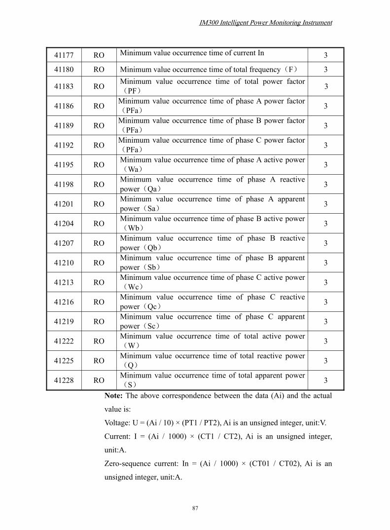
IM300 Intelligent Power Monitoring Instrument
87
41177 RO Minimum value occurrence time of current In 3
41180 RO Minimum value occurrence time of total frequency(F) 3
41183 RO Minimum value occurrence time of total power factor(PF) 3
41186 RO Minimum value occurrence time of phase A power factor(PFa) 3
41189 RO Minimum value occurrence time of phase B power factor(PFa) 3
41192 RO Minimum value occurrence time of phase C power factor(PFa) 3
41195 RO Minimum value occurrence time of phase A active power(Wa) 3
41198 RO Minimum value occurrence time of phase A reactivepower(Qa) 3
41201 RO Minimum value occurrence time of phase A apparentpower(Sa) 3
41204 RO Minimum value occurrence time of phase B active power(Wb) 3
41207 RO Minimum value occurrence time of phase B reactivepower(Qb) 3
41210 RO Minimum value occurrence time of phase B apparentpower(Sb) 3
41213 RO Minimum value occurrence time of phase C active power(Wc) 3
41216 RO Minimum value occurrence time of phase C reactivepower(Qc) 3
41219 RO Minimum value occurrence time of phase C apparentpower(Sc) 3
41222 RO Minimum value occurrence time of total active power(W)
3
41225 RO Minimum value occurrence time of total reactive power(Q) 3
41228 RO Minimum value occurrence time of total apparent power(S) 3
Note: The above correspondence between the data (Ai) and the actual
value is:
Voltage: U = (Ai / 10) × (PT1 / PT2), Ai is an unsigned integer, unit:V.
Current: I = (Ai / 1000) × (CT1 / CT2), Ai is an unsigned integer,
unit:A.
Zero-sequence current: In = (Ai / 1000) × (CT01 / CT02), Ai is an
unsigned integer, unit:A.

IM300 Intelligent Power Monitoring Instrument
88
Active power: P = Ai × (PT1 / PT2) × (CT1 / CT2), Ai signed integers,
unit:W.
Reactive power: Q = Ai × (PT1 / PT2) × (CT1 / CT2), Ai signed
integers, unit:var.
Apparent power: S = Ai × (PT1 / PT2) × (CT1 / CT2), Ai signed
integers, unit:VA.
Power factor: PF = Ai / 1000, Ai signed integers, no unit.
Frequency: F = Ai / 100, Ai as an unsigned integer, unit:Hz.
Voltage and current fundamental value address table, supports readfunction of codes 03,04
Address Type Data definition Register
41300 RO Fundamental RMS of phase A voltage 1
41301 RO Fundamental RMS of phase B voltage 1
41302 RO Fundamental RMS of phase C voltage 1
41303 RO Fundamental RMS of current Ia 1
41304 RO Fundamental RMS of current Ib 1
41305 RO Fundamental RMS of current Ic 1
41306 RO Fundamental RMS of zero-sequence current In 1Note: The above correspondence between the data (Ai) and the actual
value is:
Voltage: U = (Ai / 10) × (PT1 / PT2), Ai is an unsigned integer, unit:V.
Current: I = (Ai / 1000) × (CT1 / CT2), Ai is an unsigned integer,
unit:A.
Zero-sequence current: In = (Ai / 1000) × (CT01 / CT02), Ai is an
unsigned integer, unit:A.
Important electrical parameters quick reading address table, supports readsfunction of codes 03,04
Address Type Data Definition Register
42000 RO DI 1 1
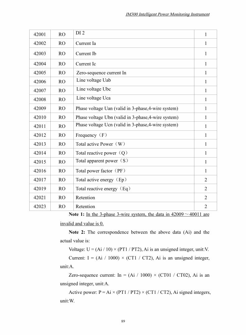
IM300 Intelligent Power Monitoring Instrument
89
42001 RO DI 2 1
42002 RO Current Ia 1
42003 RO Current Ib 1
42004 RO Current Ic 1
42005 RO Zero-sequence current In 1
42006 RO Line voltage Uab 1
42007 RO Line voltage Ubc 1
42008 RO Line voltage Uca 1
42009 RO Phase voltage Uan (valid in 3-phase,4-wire system) 1
42010 RO Phase voltage Ubn (valid in 3-phase,4-wire system) 1
42011 RO Phase voltage Ucn (valid in 3-phase,4-wire system) 1
42012 RO Frequency(F) 1
42013 RO Total active Power(W) 1
42014 RO Total reactive power(Q) 1
42015 RO Total apparent power(S) 1
42016 RO Total power factor(PF) 1
42017 RO Total active energy(Ep) 2
42019 RO Total reactive energy(Eq) 2
42021 RO Retention 2
42023 RO Retention 2Note 1: In the 3-phase 3-wire system, the data in 42009~40011 are
invalid and value is 0.
Note 2: The correspondence between the above data (Ai) and the
actual value is:
Voltage: U = (Ai / 10) × (PT1 / PT2), Ai is an unsigned integer, unit:V.
Current: I = (Ai / 1000) × (CT1 / CT2), Ai is an unsigned integer,
unit:A.
Zero-sequence current: In = (Ai / 1000) × (CT01 / CT02), Ai is an
unsigned integer, unit:A.
Active power: P = Ai × (PT1 / PT2) × (CT1 / CT2), Ai signed integers,
unit:W.

IM300 Intelligent Power Monitoring Instrument
90
Reactive power: Q = Ai × (PT1 / PT2) × (CT1 / CT2), Ai signed
integers, unit:var.
Apparent power: S = Ai × (PT1 / PT2) × (CT1 / CT2), Ai is an
unsigned integer, unit:VA.
Power factor: PF = Ai / 1000, Ai signed integers, no unit.
Frequency: F = Ai / 100, Ai as an unsigned integer, unit:Hz.
Active energy: Ep = Ai / 10, Ai unsigned long integer (0 ~
999,999,999), unit:kWh.
Reactive energy: Eq = Ai / 10, Ai unsigned long integer (0 ~
999,999,999), unit:kvarh.
Temperature address table, Suppors read function of codes 03, 04
Address Type Data Definition Register
48000 RO Temperature 1Note: The above correspondence between the data (Ai) and the actual
value is:
Temperature: T = (Ai / 10), Ai is an unsigned integer, unit:℃.
4.3. Explanation of register address Hardware version register (40010): stored in the program memory.
Software version register (40011): stored in the program memory.
Year of production (40012): Specially download to E2p after production
inspection.
Serial number of production (40013 ~ 40015): pecially download to E2p
after production inspection.
System time - register for year and month (40020): high bytes denote year,
from 00 to 99, low bytes denote month, from 1 to12.
System time - register for day and hour (40021): high byte denotes day,
from 1 to 31; low byte denotes hour, from 0 to 23.
System time - register for minute and second (40022): high byte denotes
minute, from 00 to 59; low byte denotes second, from 00 to 59.

IM300 Intelligent Power Monitoring Instrument
91
System time - millisecond register (40023): from 0 to 999.
Communication address (40030): from 1 to 254, 0 and 255 are reserved as
broadcast address. The default is 254.
Communication baud rate (BAUD) (40032): 1 ~ 5 respectively baud rate,
as follows:
Baud rate code Explanation
1 1200 bps
2 2400 bps
3 4800 bps
4 9600 bps
5 19200 bps
Check mode (PARITY) (40034): 0 to 3, representing the check mode, thefollowing table:
Check mode Code Explanation
0 No parity check, 2 end bits
1 Odd check, 1end bit
2 Even check, 1 end bit
3 No parity check, 1 end bit
Sub-station status register (40050):
Address Definitions Default value Remark
Bit0 DI change sign 0(None) Cleared after DI inquiry
Bit1 Existence sign ofhard-SOE 0(None) Cleared after all
communication SOE inquiry
Bit2 Protection action sign 0(None) Cleared after communicationinquiry or reset action
Bit3 Sign of checking time1 ( Time was notticked whenpower-on)
Cleared after remote time tick
Bit4 Existence sign ofsoft-SOE 0(None) Cleared after all
communication SOE inquiryBit5 Retention 0
Bit6 Retention 0
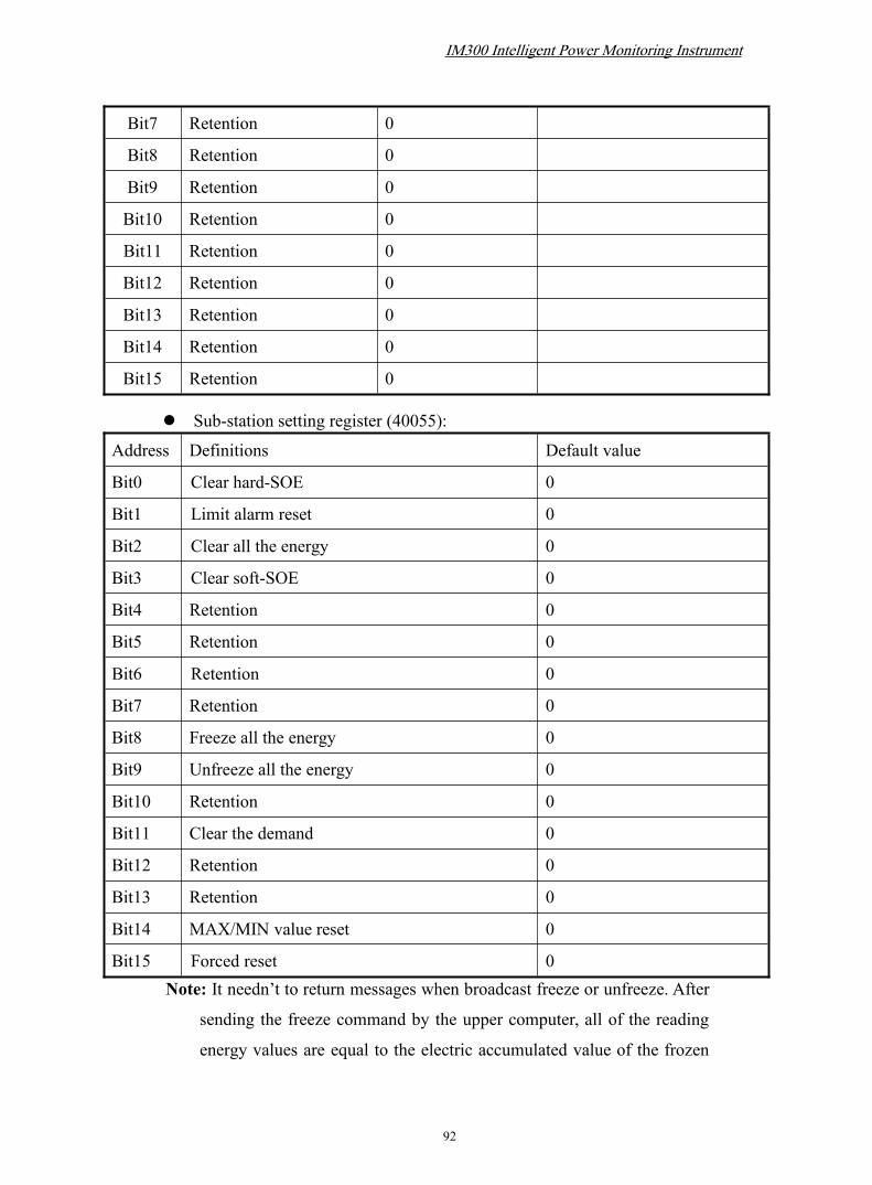
IM300 Intelligent Power Monitoring Instrument
92
Bit7 Retention 0
Bit8 Retention 0
Bit9 Retention 0
Bit10 Retention 0
Bit11 Retention 0
Bit12 Retention 0
Bit13 Retention 0
Bit14 Retention 0
Bit15 Retention 0
Sub-station setting register (40055):
Address Definitions Default value
Bit0 Clear hard-SOE 0
Bit1 Limit alarm reset 0
Bit2 Clear all the energy 0
Bit3 Clear soft-SOE 0
Bit4 Retention 0
Bit5 Retention 0
Bit6 Retention 0
Bit7 Retention 0
Bit8 Freeze all the energy 0
Bit9 Unfreeze all the energy 0
Bit10 Retention 0
Bit11 Clear the demand 0
Bit12 Retention 0
Bit13 Retention 0
Bit14 MAX/MIN value reset 0
Bit15 Forced reset 0Note: It needn’t to return messages when broadcast freeze or unfreeze. After
sending the freeze command by the upper computer, all of the reading
energy values are equal to the electric accumulated value of the frozen

IM300 Intelligent Power Monitoring Instrument
93
moment, but the internal measurement of energy value continues to
accumulate. If you want to refresh the reading total value of energy, the
upper computer must sending the unfreeze command.This facilitates the
user's unified meter reading
energy freeze and unfreeze status register (40060):
The high byte is 00, BIT1 of low byte denote energy freeze and unfreeze
status, other bits are inefficient.1 denotes freeze and 0 denotes unfreeze.
System frequency selection (40062):
5000 represents the system default frequency is 50Hz, 6000 representsthe default frequency is 60Hz.
Direction of CT wiring (40067,40068):
High byte of 40067 is the direction of A-phase CT wiring; Low byte of40067 is the direction of B-phase CT wiring. High byte of 40068 is thedirection of C-phase CT wiring. 0x00 denotes forward direction, 0xFFdenotes opposite direction.
Telemetry wiring (40070): 1 to 5 show specific wiring in the following table:Wiring Code Explanation
1 3-phase 4-wire 3CT (3P4W / 3PT + 3CT)
2 3-phase 4-wire 1CT (3P4W / 3PT + 1CT)
3 3-phase 3-wire 3CT (3P3W / 3PT + 3CT)
4 3-phase 3-wire 2CT (3P3W / 3PT (or 2PT) + 2CT)
5 3-phase 3-wire 1CT (3P4W / 3PT + 1CT)
Outputs function settings (40081): 1 ~ 2 respectively denote two relayoutputs in the following table:
Relay outputs codes Explanation
1 Pulse Output
2 Normally holding output The time of back-light (40090): 0 to 30 minutes, where 0 represents
constant light.
Association electricity parameter range of transmission output (40085):

IM300 Intelligent Power Monitoring Instrument
94
used to set the range of corresponding related energy.
Association transmission output type (40086):
BIT15 represents unidirectional/Bidirectional, 0 represents
unidirectional, 1 represents bidirectional.
BIT14 ~ BIT0 represents the association type of transmission output,
See the specific table below.
Only when the association type is active power, reactive power, power
factor, or frequency, the direction can be set to Bidirectional. 4mA represents 0 and
20mA represents full scale when set to unidirectional. When set to Bidirectional, 4mA
represents the reverse range, 20mA represents the forward range.
Example 1: When the range is set to 1.000kW, if set to unidirectional,
the output of 4mA represents 0kW, the output of 20mA represents 1.000kW, the
output of 12mA represents 0.500kW; if set to bidirectional, the output of 4mA
represents -1.000kW, 20mA represents 1.000 kW, 12mA represents 0kW.
Example 2: If the frequency F is set to Bidirectional, real-scale range is
50Hz ± range, and 12mA represents 50Hz
Related type is used to select energy which is related to transmission
output:
AssociationType Description Remark Association
Type Description Remark
1 Related Uab Unidirectional 16 Related P Unidirectional/ Bidirectional
2 Related Ubc Unidirectional 17 Related Q Unidirectional/ Bidirectional
3 Related Uca Unidirectional 18 Related S Unidirectional
4Relatedaverage ofline voltage
Unidirectional 19 Related PFa Unidirectional/ Bidirectional
5 Related Uan Unidirectional 20 Related PFb Unidirectional/ Bidirectional
6 Related Ubn Unidirectional 21 Related PFc Unidirectional/ Bidirectional
7 Related Ucn Unidirectional 22 Related Pa Unidirectional/ Bidirectional
8
Relatedaverage ofphasevoltage
Unidirectional 23 Related Pb Unidirectional/ Bidirectional

IM300 Intelligent Power Monitoring Instrument
95
9 Related Ia Unidirectional 24 Related Pc Unidirectional/ Bidirectional
10 Related Ib Unidirectional 25 Related Qa Unidirectional/ Bidirectional
11 Related Ic Unidirectional 26 Related Qb Unidirectional/ Bidirectional
12Relatedaverage ofcurrent
Unidirectional 27 Related Qc Unidirectional/ Bidirectional
13 Related In Unidirectional 28 Related Sa Unidirectional
14 Related F
Unidirectional/Bidirectional,When theBidirectional,indicates therange 50Hz ±
29 Related Sb Unidirectional
15 Related PF Unidirectional/ Bidirectional 30 Related Sc Unidirectional
Time-partition accounting settings(40092~40097):The registers are used
to set 4 rates, 48 time-periods; stepper is 0.5 hours.
The time-Period (stepper) rate is represented by 2 bits:
Bit1/bit0 00 01 10 11
Rates Sharp Peak Shoulder Off-peak
Registers 40092 ~ 40097 denote 48 time-periods(stepper):
15 14 13 12 11 10 9 8 7 6 5 4 3 2 1 0
40092 time-period 4
time-period 3
time-period 2
time-period 1
time-period 8
time-period 7
time-period 6
time-period 5
40093 time-period 12
time-period 11
time-period 10
time-period 9
time-period 16
time-period 15
time-period 14
time-period 13
40094 time-period 20
time-period 19
time-period 18
time-period 17
time-period 24
time-period 23
time-period 22
time-period 21
40095 time-period 28
time-period 27
time-period 26
time-period 25
time-period 32
time-period 31
time-period 30
time-period 29
40096 time-period 36
time-period 35
time-period 34
time-period 33
time-period 40
time-period 39
time-period 38
time-period 37
40097 time-period 44
time-period 43
time-period 42
time-period 41
time-period 48
time-period 47
time-period 46
time-period 45
Note: Stepper is 0.5 hours, “1 time-period” denotes 00:00 ~ 00:30, “2
time-period” denotes 00:30~01:00, “47 time-period” denotes 23:00~23:30,

IM300 Intelligent Power Monitoring Instrument
96
“48 time-period” denotes 23:30~00:00.
4 digital input(40500) : Status of digital input, bit0~bit3 of low byte denote 1~4
digital input respectively, the other bits are zero filled.
Bit site 7 6 5 4 3 2 1 0
High bits(zero–filled) 0 0 0 0 0 0 0 0
Low bits 0 0 0 0 DI4 DI3 DI2 DI1
Remote Protection (40501 ~ 40502): Read the alarm status of the line. The data is
explained as follows:
Bit site 7 6 5 4 3 2 1 0
40501high byte
0 0 0 0 0 0 0 0
40501low byte
Lowpowerfactor ofphase A
Lowfrequency of
phase A
Overfrequency of
phase A
lowvoltage ofphase A
Overvoltage ofphase A
Overcurrent ofphase A
The zerocurrent ofphase A
Overgroundcurrent
40502high byte
Lowpowerfactor ofphase B
Retain RetainLow
voltage ofphase B
Overvoltage ofphase B
Overcurrentof phaseB
The zerocurrent ofphase B
Retain
40502low byte
Lowpowerfactor ofphase C
Retain RetainLow
voltage ofphase C
Overvoltage ofphase C
Overcurrent ofphase C
The zerocurrent ofphase C
Retain
Register of demand occurrence time――Register 40800,40801 and 40802:
The high bits of register 40800 denote year, range: 0~99;
The low bits of register 40800 denote month,range: 1~12;
The high bits of register 40801 denote day, range: 1~31;
The low bits of register 40801 denote hour,range: 0~23;
The high bits of register 40802 denote minute,range: 0~59;

IM300 Intelligent Power Monitoring Instrument
97
The low bits of register 40802 denote second,range: 0~59.
Register of electric parameters MAX/MIN value occurrence time――Register
41060,41061 and 41062:
The high bits of register 41060 denote year, range: 0~99;
The low bits of register 41060 denote month,range: 1~12;
The high bits of register 41061 denote day, range: 1~31;
The low bits of register 41061 denote hour,range: 0~23;
The high bits of register 41062 denote minute,range: 0~59;
The low bits of register 41062 denote second,range: 0~59.
Register of quick remote signal inquiry - Register 42000:
Bit site 7 6 5 4 3 2 1 0
42000highbyte
0 0 0 0 DI4 DI3 DI2 DI1
42000lowbyte
Lowpowerfactor ofphase A
Lowfrequency of
phase A
Overfrequency of
phase A
lowvoltage ofphase A
Overvoltage ofphase A
Overcurrent ofphase A
The zerocurrent ofphase A
Overgroundcurrentalarm
42001high byte
Lowpowerfactor ofphase B
Retain RetainLow
voltage ofphase B
Overvoltage ofphase B
Overcurrentof phaseB
The zerocurrent ofphase B
Retain
42001lowbyte
Lowpowerfactor ofphase C
Retain RetainLow
voltage ofphase C
Overvoltage ofphase C
Overcurrent ofphase C
The zerocurrent ofphase C
Retain
4.4. SOE Communication Format DescriptionThe function code of SOE inquiry is 55H and alarm SOE inquiry is 56H
which is the extension part of MODBUS RTU protocol. These function codes are
used to ask SOE in the nominated address and do not support broadcasting command.
The communication format is as follows:

IM300 Intelligent Power Monitoring Instrument
98
Master query:
For example:
Field Name Example(HEX)
Slave Address 2A
Function 55(56)
CRC16Lo DE(9E)
CRC16Hi EF(EE) Sub-station response:
The length of the data-structure is 8 bytes:
Information Year Month Day Time Minu
te
Second andhigh byte ofmillisecond
Low byte ofmillisecond
Information byte:
The BIT7 and BIT6 bits denotes the status of remote signal, as shown in the
following table:
BIT7 BIT6 Definition
0 0 Remote signal from OFF to ON(0-->1)
1 1 Remote signal from ON to OFF(1-->0)
1 0 The limit alarm (0-->1) caused by this device
0 1 Undefined
BIT0~BIT5 denote the number of remote signal: single 0-31
7 6 5 4 3 2 1 0
Retention Retention
Retention Retention DI4 DI3 DI2 DI1
15 14 13 12 11 10 9 8Lowpowerfactor ofphase A
Lowfrequencyof phase A
Overfrequencyof phase A
lowvoltage ofphase A
Overvoltage ofphase A
Overcurrent ofphase A
The zerocurrent ofphase A
Overgroundcurrent
23 22 21 20 19 18 17 16Lowpower
Retain RetainLow
voltage ofOver
voltage ofOvercurrent of
The zerocurrent of
Retain

IM300 Intelligent Power Monitoring Instrument
99
factor ofphase B
phase B phase B phase B phase B
31 30 29 28 27 26 25 24Lowpowerfactor ofphase C
Retain RetainLow
voltage ofphase C
Overvoltage ofphase C
Overcurrent ofphase C
The zerocurrent ofphase C
Retain
Year bytes:Range 00~99 represents(2000~2099year);
Month bytes:Range 01~12 represents(01~12month);
Day bytes:Range 01~31 represents(01~31day);
Hour bytes:Range 00~23 represents(00~23hour);
Minute bytes:Range 00~59 represents(00~59minute);
Millisecond high byte & second bytes: BIT7 and BIT6 represent
millisecond high, from0 to 3; BIT5~BIT0 represent second, from 0 to
59.
Millisecond low bytes:Range 0~255;(Milliseconds with millisecond
High byte, Range 0 to 999).
Format for example: (the length of the SOE data structure is 8, Described time
is 2002-3-25 10:32:24 300 millisecond. Status of the third remote signal change
from ON to OFF. )
Field Name Example(Hex)
Slave Address 2A
Function 55
Byte Count 09
SOE Status 00
SOE0-Information C2
SOE0-Year 02
SOE0-Month 03
SOE0-Day 19
SOE0-hour 0A

IM300 Intelligent Power Monitoring Instrument
100
SOE0-Minute 20
SOE0-Millisecond High byte & second 58
SOE0- Millisecond low byte 2C
CRC16 Lo B6
CRC16 Hi F0The data length is decided by the SOE-number (M) and the SOE-data-structure,
the range of M is from 0 to 4. when the number of sub-stations SOE provisions of not
less than four, send four SOEs at a time, when the SOE number is less than four,
send once. If there is no SOE records, fill 0 in byte-count field.When the sub station
has a SOE record, the first byte after the byte count is the state byte of SOE (SOE
status), and its lowest bit (BIT0) indicates whether there is a SOE record at the sub
station, and when BIT0 is 0, the sub station has no SOE record; the BIT0 is 1,
indicating that the sub station has a SOE record, waiting for the main station to query
it. The other bits of this byte (BIT1 to BIT7) are reserved.
5. Transportation and storage
When being transported, the product should be packed. Violent vibration and
strike must be avoided. The ambient temperature should be between -30℃ and +80℃
and the relative humidity should be less than 95%. There should be no corrosive gas
and mildew in the air.
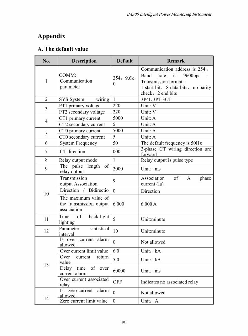
IM300 Intelligent Power Monitoring Instrument
101
Appendix
A. The default value
No. Description Default Remark
1COMM:Communicationparameter
254,9.6k,0
Communication address is 254;Baud rate is 9600bps ;Transmission format:1 start bit,8 data bits,no paritycheck,2 end bits
2 SYS:System wiringmode
1 3P4L 3PT 3CT
3 PT1 primary voltage 220 Unit: VPT2 secondary voltage 220 Unit: V
4 CT1 primary current 5000 Unit: ACT2 secondary current 5 Unit: A
5 CT0 primary current 5000 Unit: ACT0 secondary current 5 Unit: A
6 System Frequency 50 The default frequency is 50Hz
7 CT direction 000 3-phase CT wiring direction areforward
8 Relay output mode 1 Relay output is pulse type
9 The pulse length ofrelay output 2000 Unit:ms
10
Transmissionoutput Association 9 Association of A phase
current (Ia)Direction / Bidirectional
0 DirectionThe maximum value ofthe transmission outputassociation
6.000 6.000 A
11 Time of back-lightlighting 5 Unit:minute
12 Parameter statisticalinterval 10 Unit:minute
13
Is over current alarmallowed 0 Not allowed
Over current limit value 6.0 Unit:kAOver current returnvalue 5.0 Unit:kA
Delay time of overcurrent alarm 60000 Unit:ms
Over current associatedrelay OFF Indicates no associated relay
14Is zero-current alarmallowed 0 Not allowed
Zero current limit value 0 Unit:A
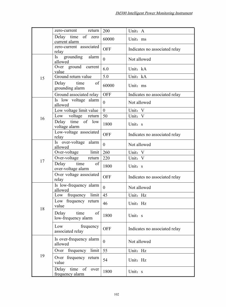
IM300 Intelligent Power Monitoring Instrument
102
zero-current returnvalue
200 Unit:ADelay time of zerocurrent alarm 60000 Unit:ms
zero-current associatedrelay OFF Indicates no associated relay
15
Is grounding alarmallowed 0 Not allowed
Over ground currentvalue 6.0 Unit:kA
Ground return value 5.0 Unit:kADelay time ofgrounding alarm 60000 Unit:ms
Ground associated relay OFF Indicates no associated relay
16
Is low voltage alarmallowed 0 Not allowed
Low voltage limit value 0 Unit:VLow voltage returnvalue
50 Unit:VDelay time of lowvoltage alarm 1800 Unit:s
Low-voltage associatedrelay OFF Indicates no associated relay
17
Is over-voltage alarmallowed 0 Not allowed
Over-voltage limitvalue
260 Unit:VOver-voltage returnvalue
220 Unit:VDelay time ofover-voltage alarm 1800 Unit:s
Over voltage associatedrelay OFF Indicates no associated relay
18
Is low-frequency alarmallowed 0 Not allowedLow frequency limitvalue
45 Unit:HzLow frequency returnvalue 46 Unit:Hz
Delay time oflow-frequency alarm 1800 Unit:s
Low frequencyassociated relay OFF Indicates no associated relay
19
Is over-frequency alarmallowed 0 Not allowed
Over frequency limitvalue
55 Unit:HzOver frequency returnvalue 54 Unit:Hz
Delay time of overfrequency alarm 1800 Unit:s

IM300 Intelligent Power Monitoring Instrument
103
Over frequencyassociated relay OFF Indicates no associated relay
20
Is low power factoralarm allowed 0 Not allowed
Low power factor limitvalue 0.5
Low power factorreturn value 0.6
Delay time of lowpower factor alarm 1800 Unit:s
Low power factorassociated relays OFF Indicates no associated relay
21 Password 0000
22 Time-period rate Each timeperiod is 3 shoulder rate
B. Technical Indicators
Standards
Standard Code Standard name LevelGB/T 13729-2002 Remote terminal unit equipmentGB/T17626.2-2006 Electrostatic discharge immunity test Level 3GB/T17626.4-2008 Electrical fast transients immunity test Level 3GB/T17626.5-2008 Surge immunity test Level 3GB/T 17626.8-2006 Frequency magnetic field immunity test Level 3GB/T 17626.12-1998 Oscillation wave immunity test Level 3
Monitor Technical indexVoltage Precision: 0.2; Range: 0-42000VCurrent Precision: 0.2; Range: 0-6000APower factor Precision: 0.5; Range: 0≤|COSΦ|≤1Active power Precision: 0.5; Range: 0-756000kWReactive power Precision: 0.5; Range: 0-756000kvarApparent power Precision: 0.5; Range: 0-756000kVAActive energy Precision:0.5; Range:0~99999999.9 kWhReactive energy Precision:0.5; Range:0~99999999.9 kvarFrequency Precision: 0.01 Hz; Range: 45-65HzHarmonic precision Precision: BDigital input Resolution ratio: 2ms; debounce time: 60msTransmission output Precision: 0.5

IM300 Intelligent Power Monitoring Instrument
104
Working parameters
Working powersupply: Range: 85VAC~265VAC/85VDC~265VDC
Power consumption: <5wWorkingenvironment: -25℃ ~ +70℃,95% non-condensing
Store temperature: -30℃ ~ +80℃Display: Sectional form LCD, sight: 64mm×55mmWeight: 400g,Only IM301:330gInternal protection: Panel:IP50, shell:IP20
Input characteristics:
Phase voltage rating: 220VAC ,range: 20VAC~264VACCurrent rating:5A; range:0.05~6 ACurrent rating:1A; range:0.01~1.2 ADigital acquisition: passive node optically isolated input (isolationvoltage 1500VDC)
Outputcharacteristics:
Relay output: 5A/250VAC(Resistive)or 5A/30VDC(Resistive)Transmission output: 4 ~ 20mA, the load resistance less than 600ohm, 500VDC isolation voltage
Communication:Communication interface:RS485Communication protocol:MODBUS-RTUCommunication speed:1200/2400/4800/9600/19200bps
Display refresherrate: <3s
Support wiringmode:
3-phase 4r-wire system 3CT, 1CT and 3-phase 3-wire 3CT, 2CT,1CT

IM300 Intelligent Power Monitoring Instrument
105
C. Order instructionsProduct model description:
IM300-U IM300-I IM301 IM302 IM303
Voltage ■ ■ ■ ■
Current ■ ■ ■ ■
System frequency ■ ■ ■ ■
Power Factor ■ ■ ■Active / reactive /apparent power ■ ■ ■
Basic energy ■ ■ ■Zero-sequence
current ■ ■ ■ ■
Unbalance ■ ■Temperature of the
equipment ■
Four-quadrant power ■ ■Maximum demand
statistics ■ ■
Time rate statistics ■
Limit alarm ■ ■
Extremum statistical ■Harmonic distortion
ratio ■ ■
Harmonic occupancy 2~15 2~31
Switch 2-ch 2-ch 2-ch 4-ch
2-ch relays ■ ■1-ch transmitter
output 4 ~ 20mA DC ■
RS485communication ■ ■ ■ ■ ■
LCD ■ ■ ■ ■ ■
According to the different selection of the specific type and function of the IM300
device (see Appendix C. order Instructions), Corresponding functions that do not have
ModelFeatures
IM300 Intelligent Power Monitoring Instrument
106
the corresponding interface are not displayed.In the data uploaded by the
communication, the corresponding value is invalid for functions that are not available.
Relevant standards (corresponding to nameplate content) to be marked when
ordering
The power supply standard configuration: AC or DC power supply
85VAC/DC ~ 265VAC/DC, 5W;
The CT rated the standard input: 5AAC, continuous 2 times overload;
Optional input : 1AAC, continuous 2 times overload.

CNABB/CNIIB/IM300/201903/REVC