Embed Size (px)
Citation preview
Illustrated Parts Manual
Model26MRT
P/N3120792
October 17, 2013

REVISION LOG
February 4, 2000 - Original Issue Of Manual (Was part of complete Manual #3123003) (Edited to 0010520 Revision 37)
October 30, 2000 - Revised (Edited to 0010520 Revision 37)
February 25, 2004 - Revised
September 15, 2007 - Revised
June 24, 2011 - Revised
October 17, 2013 - Revised
3120792 A

REVISION LOG
B 3120792
TABLE OF CONTENTS
FIGURE NO. TITLE PAGE NO.SECTION 1 - FRAME . . . . . . . . . . . . . . . . . . . . . . . . . . . . . . . . . . . . . . . . . . . . . . . . . . . . . .1-1
1-1 FRAME AND STEERING INSTALLATION . . . . . . . . . . . . . . . . . . . . . . . . . . . . . . . . . . . .1-21-2 REAR DRIVE INSTALLATION. . . . . . . . . . . . . . . . . . . . . . . . . . . . . . . . . . . . . . . . . . . . . .1-41-3 DRIVE MOTOR ASSEMBLY. . . . . . . . . . . . . . . . . . . . . . . . . . . . . . . . . . . . . . . . . . . . . . .1-81-4 DRIVE BRAKE ASSEMBLY . . . . . . . . . . . . . . . . . . . . . . . . . . . . . . . . . . . . . . . . . . . . . . .1-101-5 DRIVE AXLE ASSEMBLY . . . . . . . . . . . . . . . . . . . . . . . . . . . . . . . . . . . . . . . . . . . . . . . . .1-121-6 FRAME MOUNTED COMPONENTS INSTALLATION . . . . . . . . . . . . . . . . . . . . . . . . . . .1-141-7 HYDRAULIC DRIVE GENERATOR INSTALLATION. . . . . . . . . . . . . . . . . . . . . . . . . . . . .1-18
SECTION 2 - GROUND COMPONENTS . . . . . . . . . . . . . . . . . . . . . . . . . . . . . . . . . . . . . . .2-12-1 CONTROL VALVES & TANKS INSTALLATION . . . . . . . . . . . . . . . . . . . . . . . . . . . . . . . .2-22-2 CONTROL VALVES ASSEMBLY . . . . . . . . . . . . . . . . . . . . . . . . . . . . . . . . . . . . . . . . . . .2-62-3 VANGUARD GAS ENGINE INSTALLATION (PRIOR TO S/N 48113) . . . . . . . . . . . . . . .2-82-4 VANGUARD GAS ENGINE INSTALLATION (S/N 48113 TO PRESENT). . . . . . . . . . . . .2-142-5 DUAL FUEL INSTALLATION (VANGUARD MACHINES ONLY) . . . . . . . . . . . . . . . . . . .2-182-6 YANMAR DIESEL ENGINE INSTALLATION . . . . . . . . . . . . . . . . . . . . . . . . . . . . . . . . . .2-222-7 PISTON PUMP ASSEMBLY . . . . . . . . . . . . . . . . . . . . . . . . . . . . . . . . . . . . . . . . . . . . . .2-262-8 GEAR PUMP ASSEMBLY (YANMAR ENGINE) . . . . . . . . . . . . . . . . . . . . . . . . . . . . . . . .2-282-9 GROUND CONTROLS INSTALLATION . . . . . . . . . . . . . . . . . . . . . . . . . . . . . . . . . . . . . .2-302-10 HOOD INSTALLATIONS . . . . . . . . . . . . . . . . . . . . . . . . . . . . . . . . . . . . . . . . . . . . . . . . .2-36
SECTION 3 - SCISSOR ARMS. . . . . . . . . . . . . . . . . . . . . . . . . . . . . . . . . . . . . . . . . . . . . . .3-13-1 SCISSOR ARMS INSTALLATION . . . . . . . . . . . . . . . . . . . . . . . . . . . . . . . . . . . . . . . . . .3-2
SECTION 4 - PLATFORM. . . . . . . . . . . . . . . . . . . . . . . . . . . . . . . . . . . . . . . . . . . . . . . . . . .4-14-1 PLATFORM COMPONENTS INSTALLATION - MANUALLY OPERATED
EXTENSION . . . . . . . . . . . . . . . . . . . . . . . . . . . . . . . . . . . . . . . . . . . . . . . . . . . . . . . .4-24-2 STANDARD HANDRAILS & EXTENSION INSTALLATION (MANUALLY
OPERATED PLATFORM) . . . . . . . . . . . . . . . . . . . . . . . . . . . . . . . . . . . . . . . . . . . . . .4-64-3 WIDE PLATFORM HANDRAILS & EXTENSION INSTALLATION (MANUALLY OPERATED PLATFORM) . . . . . . . . . . . . . . . . . . . . . . . . . . . . . . . . . . . . . . . . . . . . . .4-104-4 FOLDDOWN HANDRAILS & EXTENSION INSTALLATION (MANUALLY
OPERATED PLATFORM) . . . . . . . . . . . . . . . . . . . . . . . . . . . . . . . . . . . . . . . . . . . . . .4-144-5 PLATFORM CONSOLE BOX ASSEMBLY . . . . . . . . . . . . . . . . . . . . . . . . . . . . . . . . . . . .4-184-6 CONTROLLER ASSEMBLY (PRIOR TO S/N 58990) . . . . . . . . . . . . . . . . . . . . . . . . . . . .4-224-7 CONTROLLER ASSEMBLY (S/N 58990 TO PRESENT) . . . . . . . . . . . . . . . . . . . . . . . . .4-24
SECTION 5 - CYLINDERS . . . . . . . . . . . . . . . . . . . . . . . . . . . . . . . . . . . . . . . . . . . . . . . . . .5-15-1 LIFT CYLINDER COMPONENTS ASSEMBLY (PRIOR TO S/N 26916) . . . . . . . . . . . . .5-25-2 LIFT CYLINDER COMPONENTS ASSEMBLY (S/N 26916 TO PRESENT) . . . . . . . . . . .5-65-3 STEER CYLINDER ASSEMBLY . . . . . . . . . . . . . . . . . . . . . . . . . . . . . . . . . . . . . . . . . . . .5-10
SECTION 6 - HYDRAULIC . . . . . . . . . . . . . . . . . . . . . . . . . . . . . . . . . . . . . . . . . . . . . . . . . .6-16-1 HYDRAULIC DIAGRAM - STANDARD . . . . . . . . . . . . . . . . . . . . . . . . . . . . . . . . . . . . . . .6-26-2 HYDRAULIC DIAGRAM LIST . . . . . . . . . . . . . . . . . . . . . . . . . . . . . . . . . . . . . . . . . . . . . .6-6
3120792 i
TABLE OF CONTENTS
FIGURE NO. TITLE PAGE NO.SECTION 7 - ELECTRICAL . . . . . . . . . . . . . . . . . . . . . . . . . . . . . . . . . . . . . . . . . . . . . . . . . 7-1
7-1 ELECTRICAL DIAGRAM LIST . . . . . . . . . . . . . . . . . . . . . . . . . . . . . . . . . . . . . . . . . . . . . 7-27-2 ELECTRICAL SCHEMATIC - VANGUARD . . . . . . . . . . . . . . . . . . . . . . . . . . . . . . . . . . 7-47-3 ELECTRICAL SCHEMATIC - YANMAR . . . . . . . . . . . . . . . . . . . . . . . . . . . . . . . . . . . . . 7-67-4 HARNESS AND CABLE ASSEMBLIES . . . . . . . . . . . . . . . . . . . . . . . . . . . . . . . . . . . . . 7-8
SECTION 8 - DECALS . . . . . . . . . . . . . . . . . . . . . . . . . . . . . . . . . . . . . . . . . . . . . . . . . . . . . 8-18-1 DECALS INSTALLATIONS . . . . . . . . . . . . . . . . . . . . . . . . . . . . . . . . . . . . . . . . . . . . . 8-2
SECTION 9 - RECOMMENDED SERVICE PARTS STOCK . . . . . . . . . . . . . . . . . . . . . . . . 9-1
SECTION 10 - SPECIAL OPTIONS . . . . . . . . . . . . . . . . . . . . . . . . . . . . . . . . . . . . . . . . . . . 10-1
ii 3120792
3120792
SECTION 1 FRAME
SECTION1
FRAME
TABLE OF CONTENTS
FIGURE DESCRIPTION PAGE
1-1 Frame And Steering Installation . . . . . . . . . . . . . . . . . . . . . . . . . . . . . . . . . . . . . . . . . . . . . . . . . 1-21-2 Rear Drive Installation . . . . . . . . . . . . . . . . . . . . . . . . . . . . . . . . . . . . . . . . . . . . . . . . . . . . . . . . 1-4
1-3 Drive Motor Assembly . . . . . . . . . . . . . . . . . . . . . . . . . . . . . . . . . . . . . . . . . . . . . . . . . . . . . . . . 1-8
1-4 Drive Brake Assembly . . . . . . . . . . . . . . . . . . . . . . . . . . . . . . . . . . . . . . . . . . . . . . . . . . . . . . . . 1-10
1-5 Drive Axle Assembly . . . . . . . . . . . . . . . . . . . . . . . . . . . . . . . . . . . . . . . . . . . . . . . . . . . . . . . . . . 1-121-6 Frame Mounted Components Installation . . . . . . . . . . . . . . . . . . . . . . . . . . . . . . . . . . . . . . . . . 1-14
1-7 Hydraulic Drive Generator Installation . . . . . . . . . . . . . . . . . . . . . . . . . . . . . . . . . . . . . . . . . . . . 1-18
1-1
SECTION 1 FRAMESECTION
1
FRAME
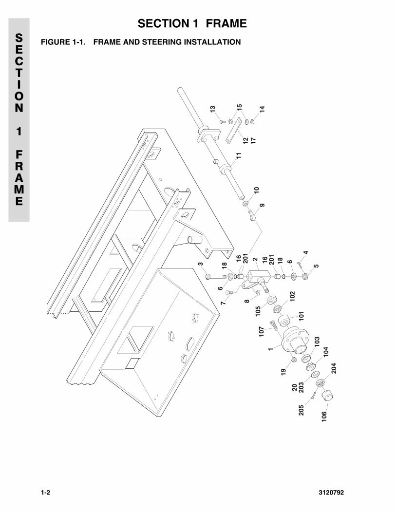
FIGURE 1-1. FRAME AND STEERING INSTALLATION
1
3
7 8
6
910
201
201
101
106
102
105
107
104
204
203
205
103
2
18
16 16
19
20
18
11
13 15 14
12 17
4
5
6
1-2 3120792
SECTION
1
FRAME
SECTION 1 FRAME
.FIGURE 1-1. FRAME AND STEERING INSTALLATIONFIG & ITEM # PART NUMBER DESCRIPTION QTY. REV.
FRAME WELDMENT OPTIONS: 12360388 Prior to S/N 27658
2360413 S/N 27658 to Present
0255118 STEERING & SPINDLES INSTALLATION Ref. 8
1 2780221 Hub Assembly (Includes Items 101-107) 2
2 4130286 Spindle Weldment (Includes Items 201-205) 23 3422610 Kingpin 2
4 3450810 Pin, Cotter 1/4” x 2 1/2” 2
5 3313003 Nut, Slotted 1 1/4”-7NC 26 0440162 Washer, Thrust 2
7 0642016 Bolt 5/8”-16NC x 2” 2
8 3312005 Locknut 5/8”-16NC 29 3841146 Rod-End 2
10 3322002 Nut, Jam 5/8”-16NC 2
11 Steer Cylinder Assembly (See Section 5 For Breakdown) Options:
1
1683239 Prior to S/N 465381683697 S/N 46538 to Present
12 3340644 Pad, Wear 1
13 0641508 Bolt 5/16”-18NC x 1” 114 3311505 Locknut 5/16”-18NC 1
15 4751500 Flatwasher 5/16” 2
16 3020022 Grease A/R17 4070809 Shim A/R
18 3780182 O-Ring 4
19 Nut, Wheel Options: 103300255 Prior to S/N 32539
3300407 S/N 32539 to Present
20 4752200 Flatwasher 3/4” 2
2780221 HUB ASSEMBLY Ref. ⎯
101 7012519 Cup, Bearing - Inner (1 Per Hub) 2
102 7012520 Cone, Bearing - Inner (1 Per Hub) 2
103 7012521 Cup, Bearing - Outer (1 Per Hub) 2104 7012522 Cone, Bearing - Outer (1 Per Hub) 2
105 7012523 Seal (1 Per Hub) 2
106 7012524 Cap, Dust (1 Per Hub) 2107 7016360 Stud, Wheel (5 Per Hub) 10
4130286 SPINDLE WELDMENT Ref. ⎯201 0961621 Bushing, Bronze (2 Per Spindle) 4202 Not Used
203 7012542 Washer (1 Per Spindle) 2
204 7012541 Nut, Slotted (1 Per Spindle) 2205 7012543 Pin, Cotter (1 Per Spindle) 2
3120792 1-3
SECTION 1 FRAMESECTION
1
FRAME
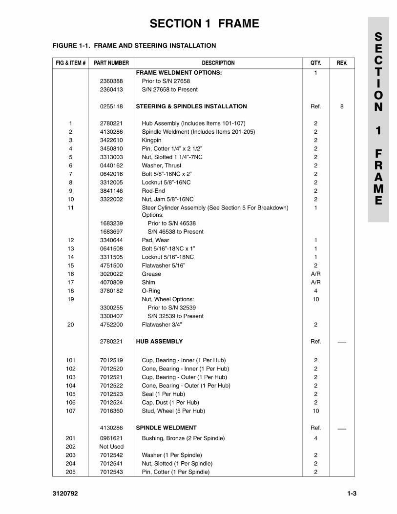
FIGURE 1-2. REAR DRIVE INSTALLATION
1-4 3120792
SECTION
1
FRAME
SECTION 1 FRAME
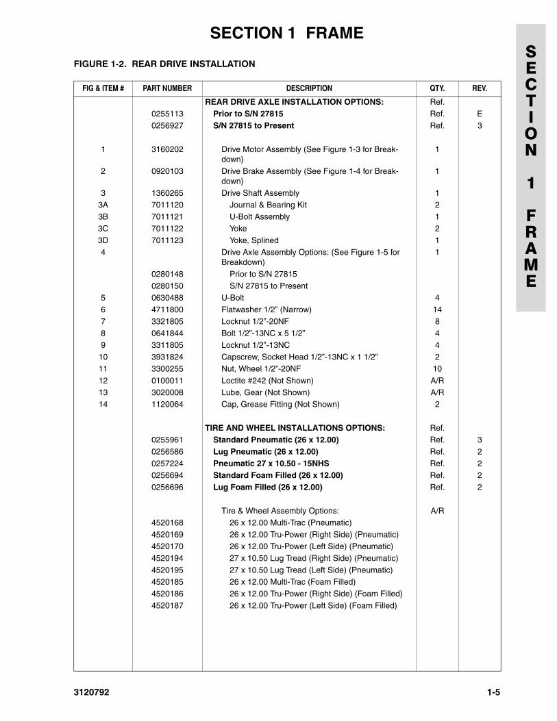
FIGURE 1-2. REAR DRIVE INSTALLATION
FIG & ITEM # PART NUMBER DESCRIPTION QTY. REV.
REAR DRIVE AXLE INSTALLATION OPTIONS: Ref.0255113 Prior to S/N 27815 Ref. E
0256927 S/N 27815 to Present Ref. 3
1 3160202 Drive Motor Assembly (See Figure 1-3 for Break-down)
1
2 0920103 Drive Brake Assembly (See Figure 1-4 for Break-down)
1
3 1360265 Drive Shaft Assembly 13A 7011120 Journal & Bearing Kit 2
3B 7011121 U-Bolt Assembly 1
3C 7011122 Yoke 23D 7011123 Yoke, Splined 1
4 Drive Axle Assembly Options: (See Figure 1-5 for Breakdown)
1
0280148 Prior to S/N 27815
0280150 S/N 27815 to Present5 0630488 U-Bolt 4
6 4711800 Flatwasher 1/2” (Narrow) 14
7 3321805 Locknut 1/2”-20NF 88 0641844 Bolt 1/2”-13NC x 5 1/2” 4
9 3311805 Locknut 1/2”-13NC 4
10 3931824 Capscrew, Socket Head 1/2”-13NC x 1 1/2” 211 3300255 Nut, Wheel 1/2”-20NF 10
12 0100011 Loctite #242 (Not Shown) A/R
13 3020008 Lube, Gear (Not Shown) A/R14 1120064 Cap, Grease Fitting (Not Shown) 2
TIRE AND WHEEL INSTALLATIONS OPTIONS: Ref.0255961 Standard Pneumatic (26 x 12.00) Ref. 3
0256586 Lug Pneumatic (26 x 12.00) Ref. 2
0257224 Pneumatic 27 x 10.50 - 15NHS Ref. 20256694 Standard Foam Filled (26 x 12.00) Ref. 2
0256696 Lug Foam Filled (26 x 12.00) Ref. 2
Tire & Wheel Assembly Options: A/R
4520168 26 x 12.00 Multi-Trac (Pneumatic)
4520169 26 x 12.00 Tru-Power (Right Side) (Pneumatic)4520170 26 x 12.00 Tru-Power (Left Side) (Pneumatic)
4520194 27 x 10.50 Lug Tread (Right Side) (Pneumatic)
4520195 27 x 10.50 Lug Tread (Left Side) (Pneumatic)4520185 26 x 12.00 Multi-Trac (Foam Filled)
4520186 26 x 12.00 Tru-Power (Right Side) (Foam Filled)
4520187 26 x 12.00 Tru-Power (Left Side) (Foam Filled)
3120792 1-5
SECTION 1 FRAMESECTION
1
FRAME
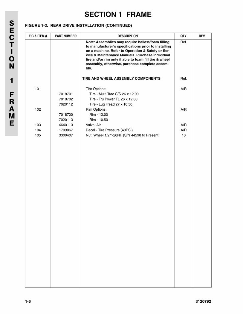
Note: Assemblies may require ballast/foam filling to manufacturer’s specifications prior to installing on a machine. Refer to Operation & Safety or Ser-vice & Maintenance Manuals. Purchase individual tire and/or rim only if able to foam fill tire & wheel assembly, otherwise, purchase complete assem-bly.
Ref.
TIRE AND WHEEL ASSEMBLY COMPONENTS Ref.
101 Tire Options: A/R7018701 Tire - Multi Trac C/S 26 x 12.00
7018702 Tire - Tru Power TL 26 x 12.00
7020112 Tire - Lug Tread 27 x 10.50 102 Rim Options: A/R
7018700 Rim - 12.00
7020113 Rim - 10.50103 4640113 Valve, Air A/R
104 1703067 Decal - Tire Pressure (40PSI) A/R
105 3300407 Nut, Wheel 1/2*”-20NF (S/N 44598 to Present) 10
FIGURE 1-2. REAR DRIVE INSTALLATION (CONTINUED)
FIG & ITEM # PART NUMBER DESCRIPTION QTY. REV.
1-6 3120792
SECTION
1
FRAME
SECTION 1 FRAME
FIGURE 1-2. REAR DRIVE INSTALLATION (CONTINUED)FIG & ITEM # PART NUMBER DESCRIPTION QTY. REV.
3120792 1-7
SECTION 1 FRAMESECTION
1
FRAME
FIGURE 1-3. DRIVE MOTOR ASSEMBLY
42
41
40
37 44
2725
24
6
9
14
1413 11
12
10
7
43
39
38
26
5
4
3
2
2
24
20
1
16
15
17
18
2
22
21
19
1-8 3120792
SECTION
1
FRAME
SECTION 1 FRAME
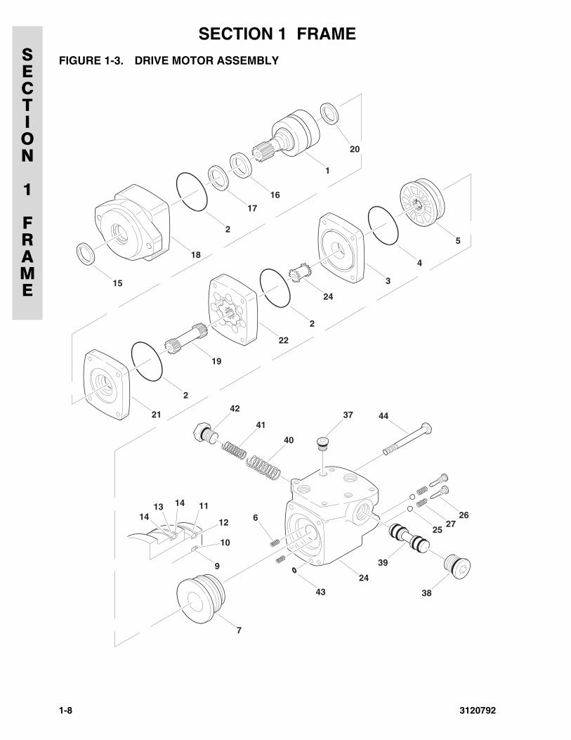
.FIGURE 1-3. DRIVE MOTOR ASSEMBLYFIG & ITEM # PART NUMBER DESCRIPTION QTY. REV.
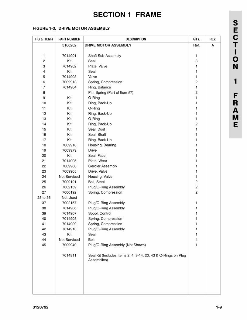
3160202 DRIVE MOTOR ASSEMBLY Ref. A
1 7014901 Shaft Sub-Assembly 1
2 Kit Seal 3
3 7014902 Plate, Valve 14 Kit Seal 1
5 7014903 Valve 1
6 7009913 Spring, Compression 27 7014904 Ring, Balance 1
8 Pin, Spring (Part of Item #7) 2
9 Kit O-Ring 110 Kit Ring, Back-Up 1
11 Kit O-Ring 1
12 Kit Ring, Back-Up 113 Kit O-Ring 1
14 Kit Ring, Back-Up 2
15 Kit Seal, Dust 116 Kit Seal, Shaft 1
17 Kit Ring, Back-Up 1
18 7009918 Housing, Bearing 119 7009979 Drive 1
20 Kit Seal, Face 1
21 7014905 Plate, Wear 122 7009980 Geroler Assembly 1
23 7009905 Drive, Valve 1
24 Not Serviced Housing, Valve 125 7000191 Ball, Steel 2
26 7002159 Plug/O-Ring Assembly 2
27 7000192 Spring, Compression 228 to 36 Not Used
37 7002157 Plug/O-Ring Assembly 1
38 7014906 Plug/O-Ring Assembly 139 7014907 Spool, Control 1
40 7014908 Spring, Compression 1
41 7014909 Spring, Compression 142 7014910 Plug/O-Ring Assembly 1
43 Kit Seal 1
44 Not Serviced Bolt 445 7009940 Plug/O-Ring Assembly (Not Shown) 1
7014911 Seal Kit (Includes Items 2, 4, 9-14, 20, 43 & O-Rings on Plug Assemblies)
3120792 1-9
SECTION 1 FRAMESECTION
1
FRAME
FIGURE 1-4. DRIVE BRAKE ASSEMBLY
22
239
11
20
10
12
24
14133
42
5
1
15
19
16
1718
6
20
7
8
2131
1-10 3120792
SECTION
1
FRAME
SECTION 1 FRAME
.FIGURE 1-4. DRIVE BRAKE ASSEMBLYFIG & ITEM # PART NUMBER DESCRIPTION QTY. REV.
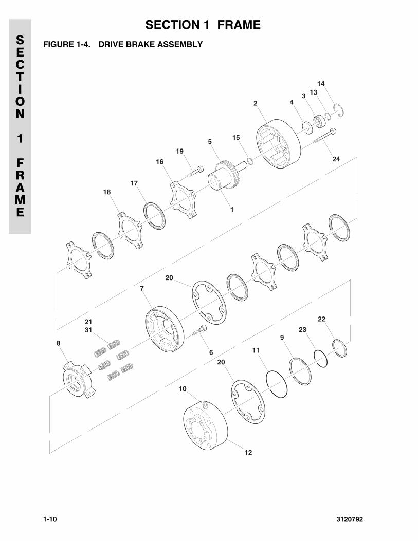
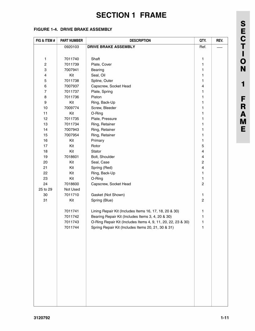
0920103 DRIVE BRAKE ASSEMBLY Ref. ⎯
1 7011740 Shaft 1
2 7011739 Plate, Cover 1
3 7007941 Bearing 14 Kit Seal, Oil 1
5 7011738 Spline, Outer 1
6 7007937 Capscrew, Socket Head 47 7011737 Plate, Spring 1
8 7011736 Piston 1
9 Kit Ring, Back-Up 110 7009774 Screw, Bleeder 1
11 Kit O-Ring 1
12 7011735 Plate, Pressure 113 7011734 Ring, Retainer 1
14 7007943 Ring, Retainer 1
15 7007954 Ring, Retainer 116 Kit Primary 1
17 Kit Rotor 5
18 Kit Stator 419 7018601 Bolt, Shoulder 4
20 Kit Seal, Case 2
21 Kit Spring (Red) 422 Kit Ring, Back-Up 1
23 Kit O-Ring 1
24 7018600 Capscrew, Socket Head 225 to 29 Not Used
30 7011710 Gasket (Not Shown) 1
31 Kit Spring (Blue) 2
7011741 Lining Repair Kit (Includes Items 16, 17, 18, 20 & 30) 1
7011742 Bearing Repair Kit (Includes Items 3, 4, 20 & 30) 17011743 O-Ring Repair Kit (Includes Items 4, 9, 11, 20, 22, 23 & 30) 1
7011744 Spring Repair Kit (Includes Items 20, 21, 30 & 31) 1
3120792 1-11
SECTION 1 FRAMESECTION
1
FRAME
FIGURE 1-5. DRIVE AXLE ASSEMBLY
16
17
19
18
20
3032
33
34
35
36
31
38
39
37
23
39
21
14
152
3
1
4
5
6
89
1112
7
10
1-12 3120792
SECTION
1
FRAME
SECTION 1 FRAME
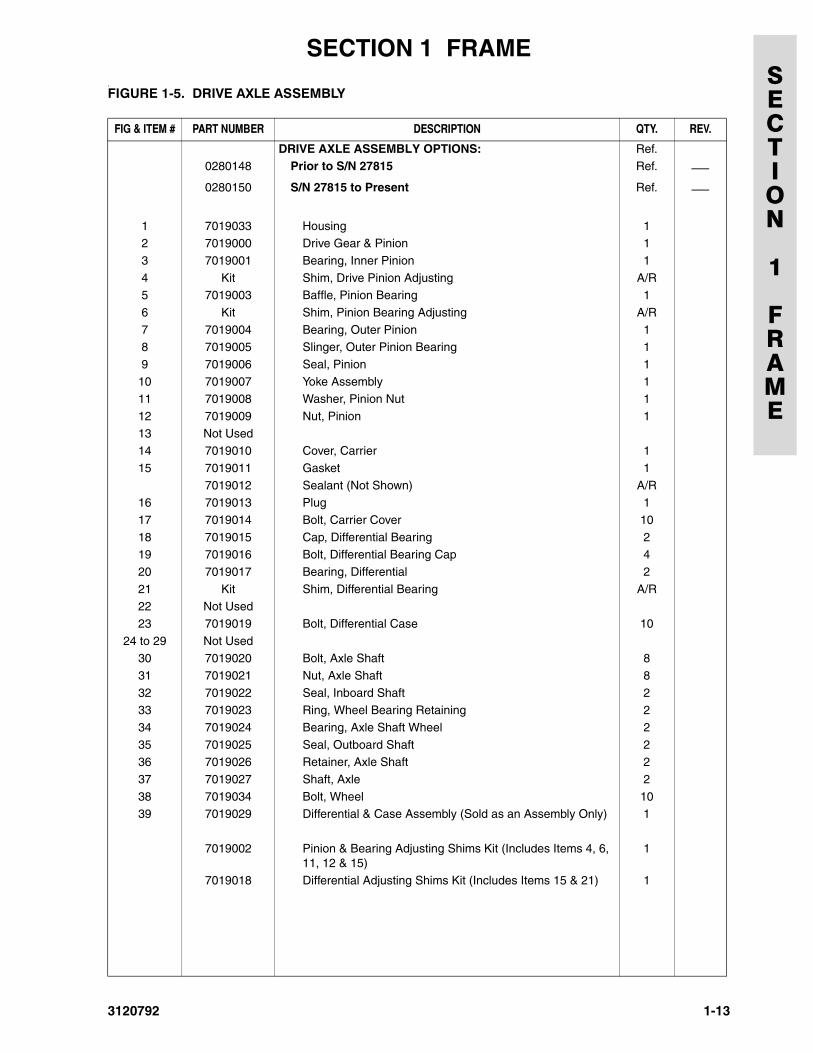
.FIGURE 1-5. DRIVE AXLE ASSEMBLYFIG & ITEM # PART NUMBER DESCRIPTION QTY. REV.
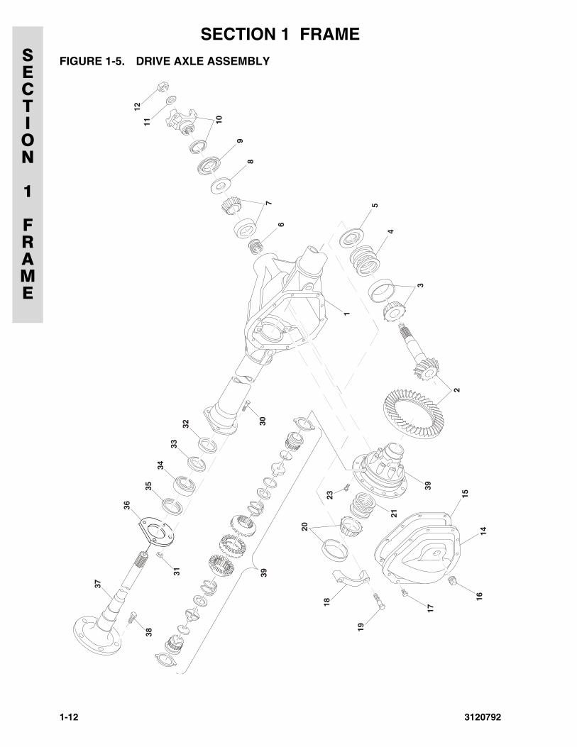
DRIVE AXLE ASSEMBLY OPTIONS: Ref.0280148 Prior to S/N 27815 Ref. ⎯0280150 S/N 27815 to Present Ref. ⎯
1 7019033 Housing 12 7019000 Drive Gear & Pinion 1
3 7019001 Bearing, Inner Pinion 1
4 Kit Shim, Drive Pinion Adjusting A/R5 7019003 Baffle, Pinion Bearing 1
6 Kit Shim, Pinion Bearing Adjusting A/R
7 7019004 Bearing, Outer Pinion 18 7019005 Slinger, Outer Pinion Bearing 1
9 7019006 Seal, Pinion 1
10 7019007 Yoke Assembly 111 7019008 Washer, Pinion Nut 1
12 7019009 Nut, Pinion 1
13 Not Used14 7019010 Cover, Carrier 1
15 7019011 Gasket 1
7019012 Sealant (Not Shown) A/R16 7019013 Plug 1
17 7019014 Bolt, Carrier Cover 10
18 7019015 Cap, Differential Bearing 219 7019016 Bolt, Differential Bearing Cap 4
20 7019017 Bearing, Differential 2
21 Kit Shim, Differential Bearing A/R22 Not Used
23 7019019 Bolt, Differential Case 10
24 to 29 Not Used30 7019020 Bolt, Axle Shaft 8
31 7019021 Nut, Axle Shaft 8
32 7019022 Seal, Inboard Shaft 233 7019023 Ring, Wheel Bearing Retaining 2
34 7019024 Bearing, Axle Shaft Wheel 2
35 7019025 Seal, Outboard Shaft 236 7019026 Retainer, Axle Shaft 2
37 7019027 Shaft, Axle 2
38 7019034 Bolt, Wheel 1039 7019029 Differential & Case Assembly (Sold as an Assembly Only) 1
7019002 Pinion & Bearing Adjusting Shims Kit (Includes Items 4, 6, 11, 12 & 15)
1
7019018 Differential Adjusting Shims Kit (Includes Items 15 & 21) 1
3120792 1-13
SECTION 1 FRAMESECTION
1
FRAME
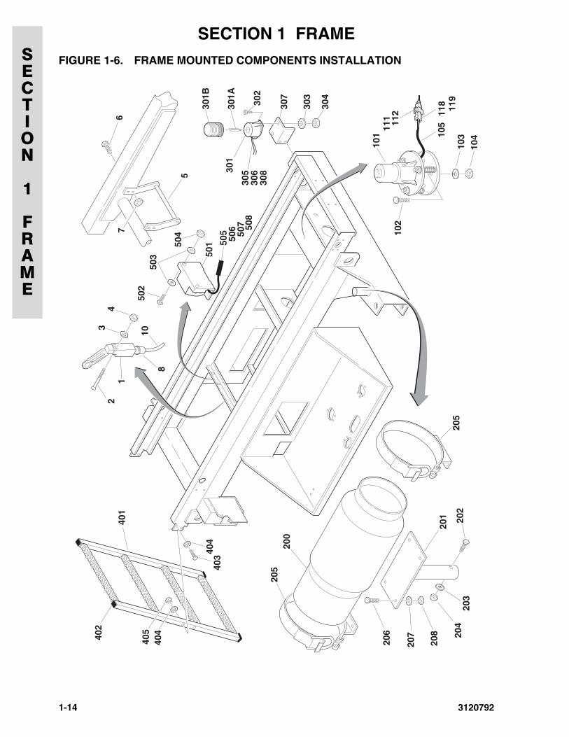
FIGURE 1-6. FRAME MOUNTED COMPONENTS INSTALLATION
1-14 3120792
SECTION
1
FRAME
SECTION 1 FRAME
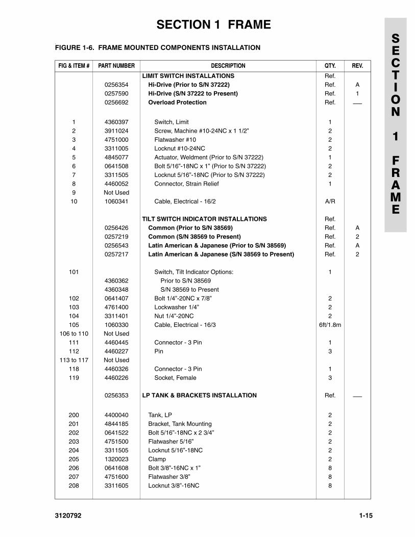
.FIGURE 1-6. FRAME MOUNTED COMPONENTS INSTALLATIONFIG & ITEM # PART NUMBER DESCRIPTION QTY. REV.
LIMIT SWITCH INSTALLATIONS Ref.0256354 Hi-Drive (Prior to S/N 37222) Ref. A
0257590 Hi-Drive (S/N 37222 to Present) Ref. 1
0256692 Overload Protection Ref. ⎯
1 4360397 Switch, Limit 1
2 3911024 Screw, Machine #10-24NC x 1 1/2” 2
3 4751000 Flatwasher #10 24 3311005 Locknut #10-24NC 2
5 4845077 Actuator, Weldment (Prior to S/N 37222) 1
6 0641508 Bolt 5/16”-18NC x 1” (Prior to S/N 37222) 27 3311505 Locknut 5/16”-18NC (Prior to S/N 37222) 2
8 4460052 Connector, Strain Relief 1
9 Not Used10 1060341 Cable, Electrical - 16/2 A/R
TILT SWITCH INDICATOR INSTALLATIONS Ref.0256426 Common (Prior to S/N 38569) Ref. A
0257219 Common (S/N 38569 to Present) Ref. 2
0256543 Latin American & Japanese (Prior to S/N 38569) Ref. A0257217 Latin American & Japanese (S/N 38569 to Present) Ref. 2
101 Switch, Tilt Indicator Options: 14360362 Prior to S/N 38569
4360348 S/N 38569 to Present
102 0641407 Bolt 1/4”-20NC x 7/8” 2103 4761400 Lockwasher 1/4” 2
104 3311401 Nut 1/4”-20NC 2
105 1060330 Cable, Electrical - 16/3 6ft/1.8m106 to 110 Not Used
111 4460445 Connector - 3 Pin 1
112 4460227 Pin 3113 to 117 Not Used
118 4460326 Connector - 3 Pin 1
119 4460226 Socket, Female 3
0256353 LP TANK & BRACKETS INSTALLATION Ref. ⎯
200 4400040 Tank, LP 2
201 4844185 Bracket, Tank Mounting 2
202 0641522 Bolt 5/16”-18NC x 2 3/4” 2
203 4751500 Flatwasher 5/16” 2204 3311505 Locknut 5/16”-18NC 2
205 1320023 Clamp 2
206 0641608 Bolt 3/8”-16NC x 1” 8207 4751600 Flatwasher 3/8” 8
208 3311605 Locknut 3/8”-16NC 8
3120792 1-15
SECTION 1 FRAMESECTION
1
FRAME
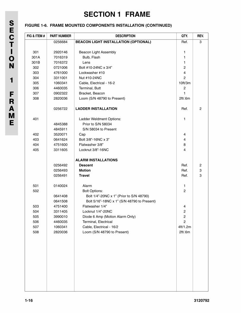
0256684 BEACON LIGHT INSTALLATION (OPTIONAL) Ref. 3
301 2920146 Beacon Light Assembly 1
301A 7016319 Bulb, Flash 1
301B 7016372 Lens 1302 0721006 Bolt #10-24NC x 3/4” 2
303 4761000 Lockwasher #10 4
304 3311001 Nut #10-24NC 2305 1060341 Cable, Electrical - 16-2 10ft/3m
306 4460035 Terminal, Butt 2
307 0902322 Bracket, Beacon 1308 2820036 Loom (S/N 48790 to Present) 2ft/.6m
0256722 LADDER INSTALLATION Ref. 2
401 Ladder Weldment Options: 1
4845388 Prior to S/N 580344845911 S/N 58034 to Present
402 3520071 Cap 4
403 0641624 Bolt 3/8”-16NC x 3” 4404 4751600 Flatwasher 3/8” 8
405 3311605 Locknut 3/8”-16NC 4
ALARM INSTALLATIONS0256492 Descent Ref. 2
0256493 Motion Ref. 30256491 Travel Ref. 3
501 0140024 Alarm 1502 Bolt Options: 2
0641408 Bolt 1/4”-20NC x 1” (Prior to S/N 48790)
0641508 Bolt 5/16”-18NC x 1” (S/N 48790 to Present)503 4751400 Flatwasher 1/4” 4
504 3311405 Locknut 1/4”-20NC 2
505 3990010 Diode 6 Amp (Motion Alarm Only) 2506 4460035 Terminal, Electrical 2
507 1060341 Cable, Electrical - 16/2 4ft/1.2m
508 2820036 Loom (S/N 48790 to Present) 2ft/.6m
FIGURE 1-6. FRAME MOUNTED COMPONENTS INSTALLATION (CONTINUED)
FIG & ITEM # PART NUMBER DESCRIPTION QTY. REV.
1-16 3120792
SECTION
1
FRAME
SECTION 1 FRAME
FIGURE 1-6. FRAME MOUNTED COMPONENTS INSTALLATION (CONTINUED)FIG & ITEM # PART NUMBER DESCRIPTION QTY. REV.
3120792 1-17
SECTION 1 FRAMESECTION
1
FRAME
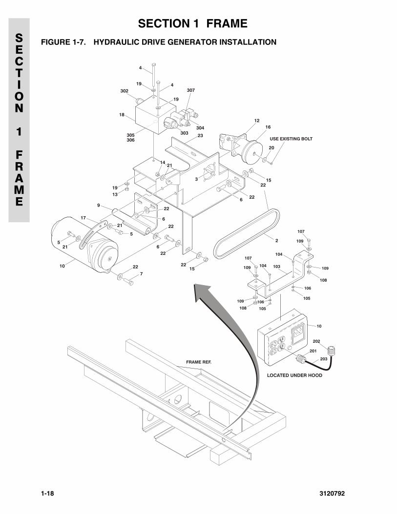
FIGURE 1-7. HYDRAULIC DRIVE GENERATOR INSTALLATION
FRAME REF.
103
104
104
107
109
107
109
105
108
10
105108
201
203
202
106109
106
109
LOCATED UNDER HOOD
USE EXISTING BOLT
2
6 22
1522
1522
22
22
22
22
6
6
7
10
21
21
21
3
13
17
1216
20
5
5
9
4
4
14
18
19
23
19
19
302 307
303304
305306
1-18 3120792
SECTION
1
FRAME
SECTION 1 FRAME
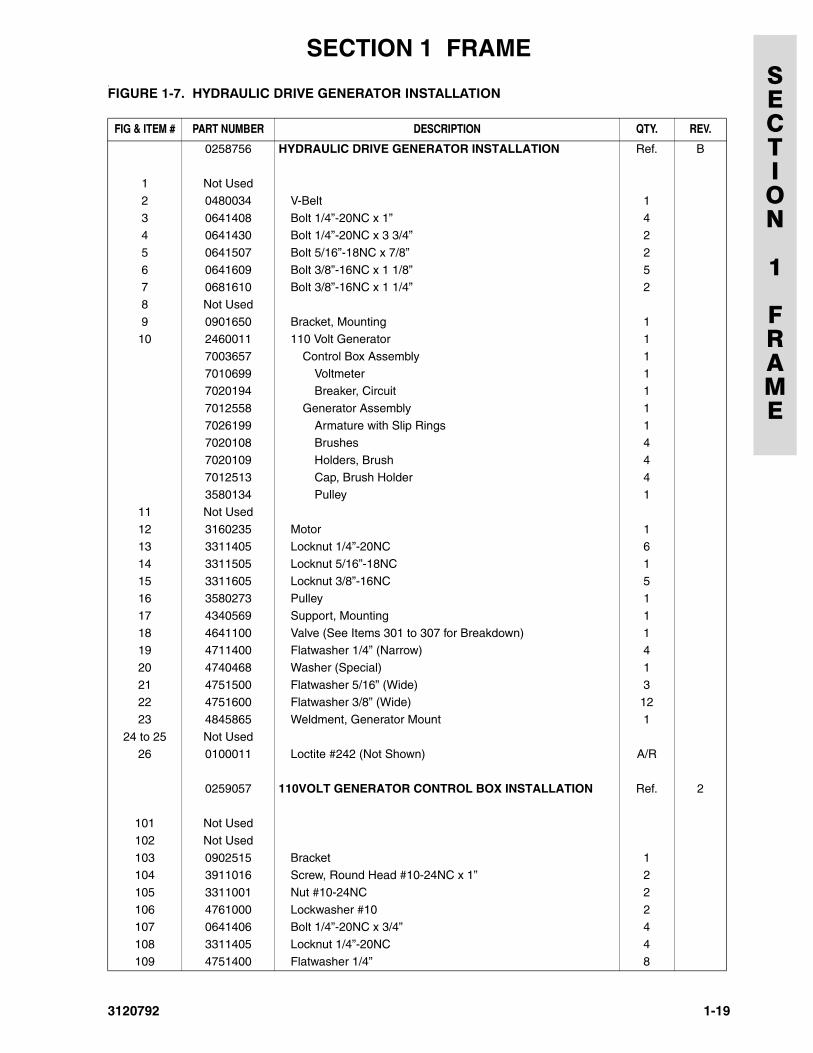
.FIGURE 1-7. HYDRAULIC DRIVE GENERATOR INSTALLATIONFIG & ITEM # PART NUMBER DESCRIPTION QTY. REV.
0258756 HYDRAULIC DRIVE GENERATOR INSTALLATION Ref. B
1 Not Used
2 0480034 V-Belt 1
3 0641408 Bolt 1/4”-20NC x 1” 44 0641430 Bolt 1/4”-20NC x 3 3/4” 2
5 0641507 Bolt 5/16”-18NC x 7/8” 2
6 0641609 Bolt 3/8”-16NC x 1 1/8” 57 0681610 Bolt 3/8”-16NC x 1 1/4” 2
8 Not Used
9 0901650 Bracket, Mounting 110 2460011 110 Volt Generator 1
7003657 Control Box Assembly 1
7010699 Voltmeter 17020194 Breaker, Circuit 1
7012558 Generator Assembly 1
7026199 Armature with Slip Rings 17020108 Brushes 4
7020109 Holders, Brush 4
7012513 Cap, Brush Holder 43580134 Pulley 1
11 Not Used
12 3160235 Motor 113 3311405 Locknut 1/4”-20NC 6
14 3311505 Locknut 5/16”-18NC 1
15 3311605 Locknut 3/8”-16NC 516 3580273 Pulley 1
17 4340569 Support, Mounting 1
18 4641100 Valve (See Items 301 to 307 for Breakdown) 119 4711400 Flatwasher 1/4” (Narrow) 4
20 4740468 Washer (Special) 1
21 4751500 Flatwasher 5/16” (Wide) 322 4751600 Flatwasher 3/8” (Wide) 12
23 4845865 Weldment, Generator Mount 1
24 to 25 Not Used26 0100011 Loctite #242 (Not Shown) A/R
0259057 110VOLT GENERATOR CONTROL BOX INSTALLATION Ref. 2
101 Not Used
102 Not Used
103 0902515 Bracket 1104 3911016 Screw, Round Head #10-24NC x 1” 2
105 3311001 Nut #10-24NC 2
106 4761000 Lockwasher #10 2107 0641406 Bolt 1/4”-20NC x 3/4” 4
108 3311405 Locknut 1/4”-20NC 4
109 4751400 Flatwasher 1/4” 8
3120792 1-19
SECTION 1 FRAMESECTION
1
FRAME
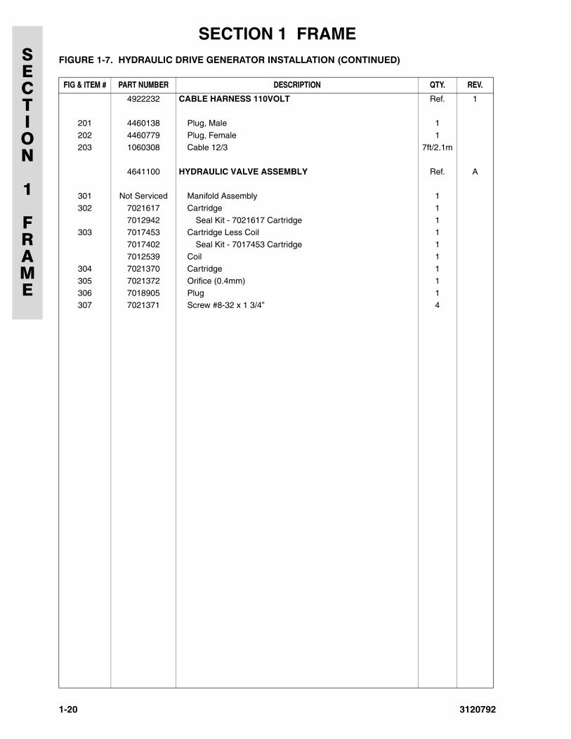
4922232 CABLE HARNESS 110VOLT Ref. 1
201 4460138 Plug, Male 1
202 4460779 Plug, Female 1
203 1060308 Cable 12/3 7ft/2.1m
4641100 HYDRAULIC VALVE ASSEMBLY Ref. A
301 Not Serviced Manifold Assembly 1
302 7021617 Cartridge 1
7012942 Seal Kit - 7021617 Cartridge 1303 7017453 Cartridge Less Coil 1
7017402 Seal Kit - 7017453 Cartridge 1
7012539 Coil 1304 7021370 Cartridge 1
305 7021372 Orifice (0.4mm) 1
306 7018905 Plug 1307 7021371 Screw #8-32 x 1 3/4” 4
FIGURE 1-7. HYDRAULIC DRIVE GENERATOR INSTALLATION (CONTINUED)
FIG & ITEM # PART NUMBER DESCRIPTION QTY. REV.
1-20 3120792
3120792
SECTION 2 GROUND COMPONENTS
SECTION
2
GROUND
COMPONENTS
TABLE OF CONTENTS
FIGURE DESCRIPTION PAGE
2-1 Control Valves & Tanks Installation . . . . . . . . . . . . . . . . . . . . . . . . . . . . . . . . . . . . . . . . . . . . . . . 2-22-2 Control Valve Assembly . . . . . . . . . . . . . . . . . . . . . . . . . . . . . . . . . . . . . . . . . . . . . . . . . . . . . . . 2-6
2-3 Vanguard Gas Engine Installation (Prior to S/N 48113) . . . . . . . . . . . . . . . . . . . . . . . . . . . . . . . 2-8
2-4 Vanguard Gas Engine Installation (S/N 48113 to Present) . . . . . . . . . . . . . . . . . . . . . . . . . . . . . 2-14
2-5 Dual Fuel Installation (Vanguard Machines Only) . . . . . . . . . . . . . . . . . . . . . . . . . . . . . . . . . . . . 2-182-6 Yanmar Diesel Engine Installation. . . . . . . . . . . . . . . . . . . . . . . . . . . . . . . . . . . . . . . . . . . . . . . . 2-22
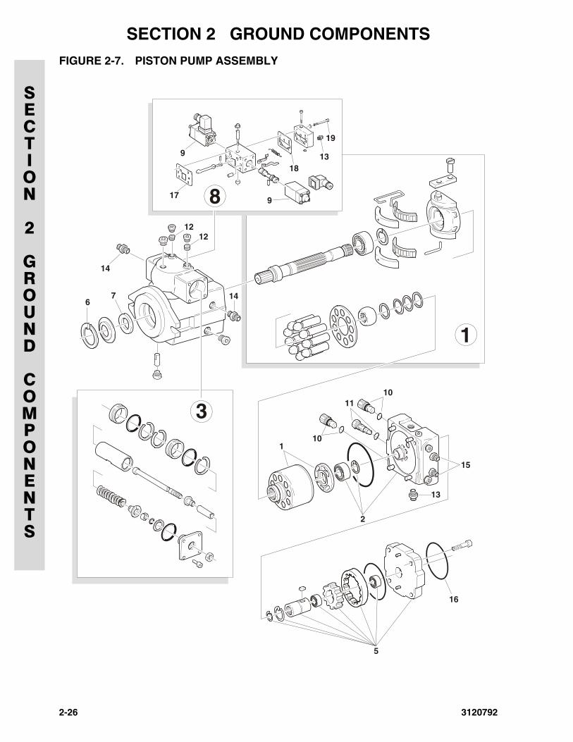
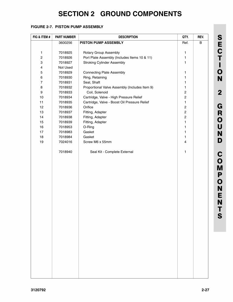
2-7 Piston Pump Assembly . . . . . . . . . . . . . . . . . . . . . . . . . . . . . . . . . . . . . . . . . . . . . . . . . . . . . . . . 2-26
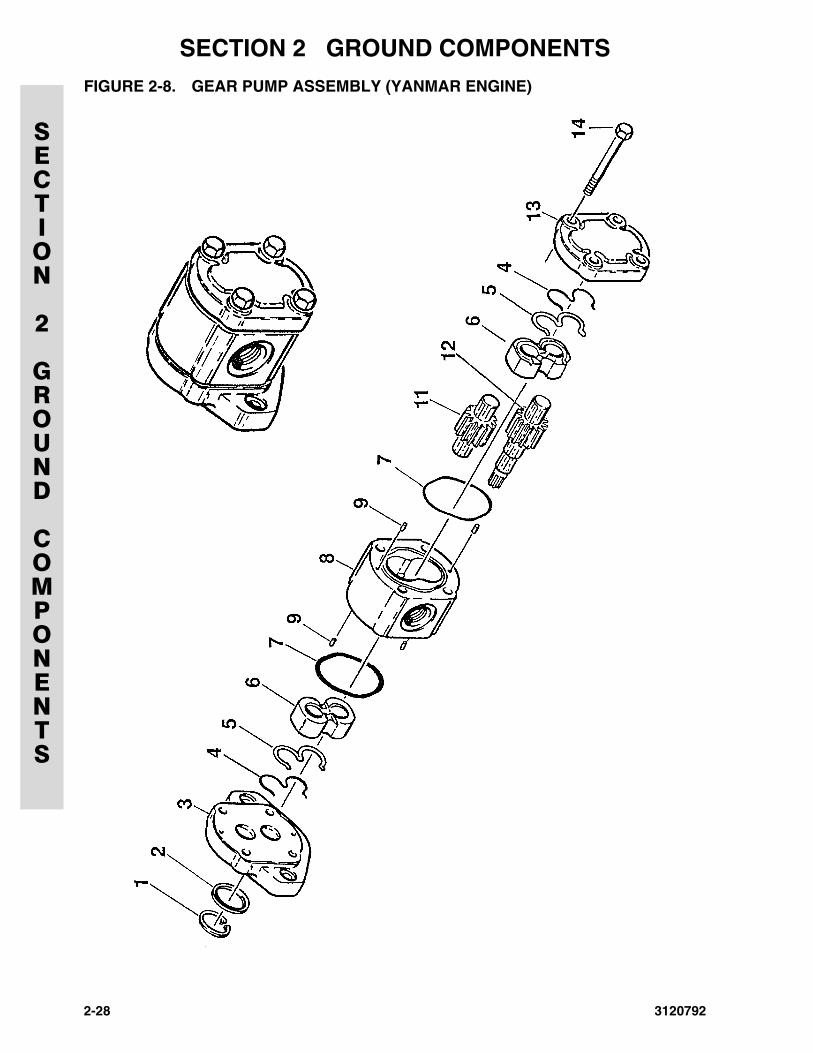
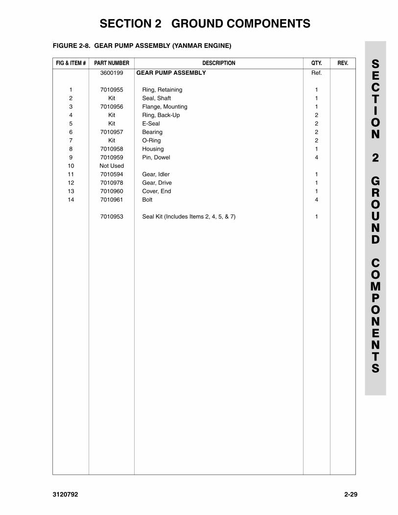
2-8 Gear Pump Assembly (Yanmar Engine) . . . . . . . . . . . . . . . . . . . . . . . . . . . . . . . . . . . . . . . . . . . 2-282-9 Ground Control Installation . . . . . . . . . . . . . . . . . . . . . . . . . . . . . . . . . . . . . . . . . . . . . . . . . . . . . 2-30
2-10 Hood Installations . . . . . . . . . . . . . . . . . . . . . . . . . . . . . . . . . . . . . . . . . . . . . . . . . . . . . . . . . . . . 2-36
2-1
SECTION 2 GROUND COMPONENTS
SECTION
2
GROUND
COMPONENTS
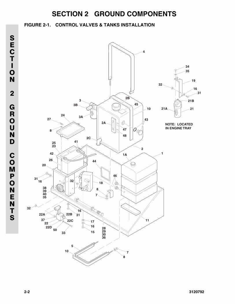
FIGURE 2-1. CONTROL VALVES & TANKS INSTALLATION
4
2B
4510
44
28
38
25
8
3116
8
8
18
46
32
7
7
31
111716
15
22C
22B22A
372222D
5033
16
29
39
26
42
20
41
30
40
23
2724
36
35
32
33B
3A
2A
47
48
43
211A
5
10
3435
19
31
21
NOTE: LOCATEDIN ENGINE TRAY
21A
21B
3216
2C
2-2 3120792
SECTION 2 GROUND COMPONENTS
SECTION
2
GROUND
COMPONENTS
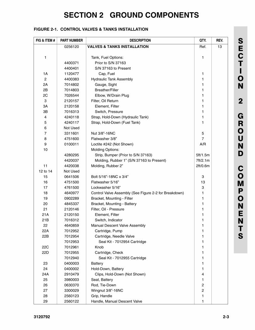
.FIGURE 2-1. CONTROL VALVES & TANKS INSTALLATION
FIG & ITEM # PART NUMBER DESCRIPTION QTY. REV.
0256120 VALVES & TANKS INSTALLATION Ref. 13
1 Tank, Fuel Options: 1
4400371 Prior to S/N 37163
4400401 S/N 37163 to Present1A 1120477 Cap, Fuel 1
2 4400383 Hydraulic Tank Assembly 1
2A 7014802 Gauge, Sight 12B 7014803 Breather/Filler 1
2C 7026544 Elbow, W/Drain Plug 1
3 2120157 Filter, Oil Return 13A 2120158 Element, Filter 1
3B 7016313 Switch, Pressure 1
4 4240118 Strap, Hold-Down (Hydraulic Tank) 15 4240117 Strap, Hold-Down (Fuel Tank) 1
6 Not Used
7 3311601 Nut 3/8”-16NC 58 4751600 Flatwasher 3/8” 7
9 0100011 Loctite #242 (Not Shown) A/R
10 Molding Options:4280295 Strip, Bumper (Prior to S/N 37163) 5ft/1.5m
4420037 Molding, Rubber 1” (S/N 37163 to Present) 7ft/2.1m
11 4420038 Molding, Rubber 2” 2ft/0.6m12 to 14 Not Used
15 0641506 Bolt 5/16”-18NC x 3/4” 3
16 4751500 Flatwasher 5/16” 1317 4761500 Lockwasher 5/16” 3
18 4640977 Control Valve Assembly (See Figure 2-2 for Breakdown) 1
19 0902289 Bracket, Mounting - Filter 120 4845337 Bracket, Mounting - Battery 1
21 2120146 Filter, Oil - Pressure 1
21A 2120150 Element, Filter 121B 7016312 Switch, Indicator 1
22 4640859 Manual Descent Valve Assembly 1
22A 7012952 Cartridge, Pump 122B 7012954 Cartridge, Needle Valve 1
7012953 Seal Kit - 7012954 Cartridge 1
22C 7012961 Knob 122D 7012955 Cartridge, Check 1
7012940 Seal Kit - 7012955 Cartridge 1
23 0400003 Battery 1
24 0400002 Hold-Down, Battery 124A 2910479 Clips, Hold-Down (Not Shown) 4
25 3980003 Seat, Battery 1
26 0630370 Rod, Tie-Down 227 3300029 Wingnut 3/8”-16NC 2
28 2560123 Grip, Handle 1
29 2560122 Handle, Manual Descent Valve 1
3120792 2-3
SECTION 2 GROUND COMPONENTS
SECTION
2
GROUND
COMPONENTS
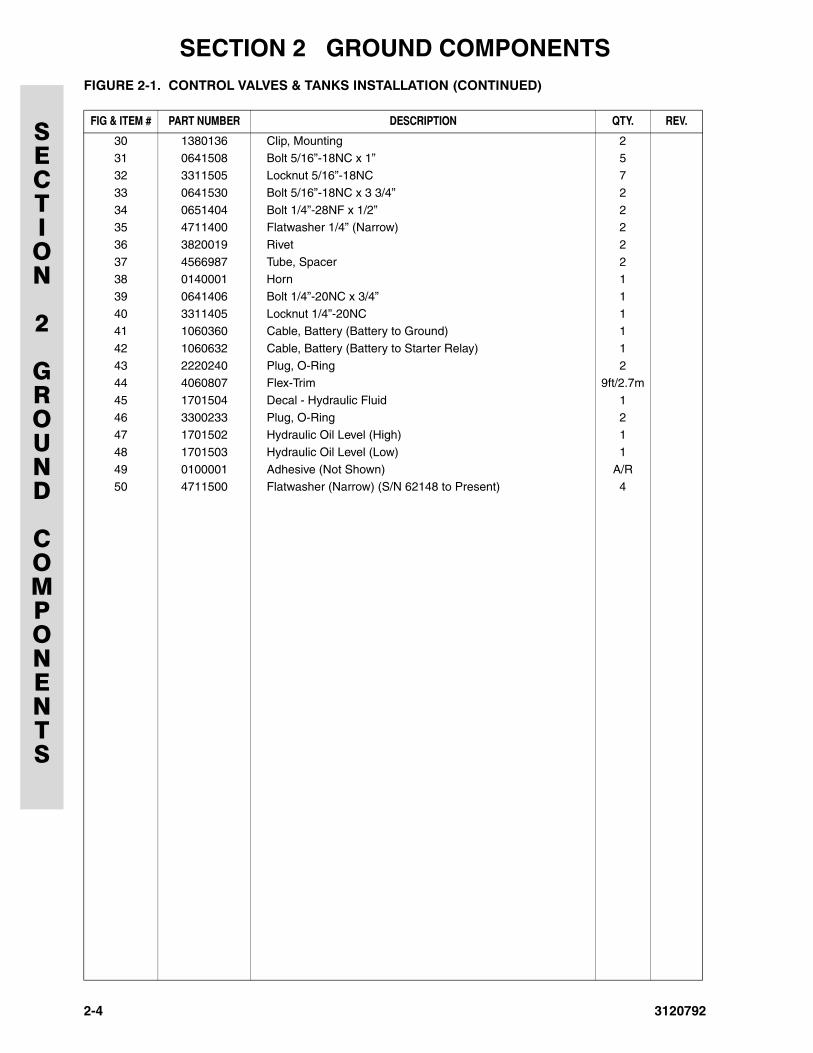
30 1380136 Clip, Mounting 231 0641508 Bolt 5/16”-18NC x 1” 5
32 3311505 Locknut 5/16”-18NC 7
33 0641530 Bolt 5/16”-18NC x 3 3/4” 2
34 0651404 Bolt 1/4”-28NF x 1/2” 235 4711400 Flatwasher 1/4” (Narrow) 2
36 3820019 Rivet 2
37 4566987 Tube, Spacer 238 0140001 Horn 1
39 0641406 Bolt 1/4”-20NC x 3/4” 1
40 3311405 Locknut 1/4”-20NC 141 1060360 Cable, Battery (Battery to Ground) 1
42 1060632 Cable, Battery (Battery to Starter Relay) 1
43 2220240 Plug, O-Ring 244 4060807 Flex-Trim 9ft/2.7m
45 1701504 Decal - Hydraulic Fluid 1
46 3300233 Plug, O-Ring 247 1701502 Hydraulic Oil Level (High) 1
48 1701503 Hydraulic Oil Level (Low) 1
49 0100001 Adhesive (Not Shown) A/R50 4711500 Flatwasher (Narrow) (S/N 62148 to Present) 4
FIGURE 2-1. CONTROL VALVES & TANKS INSTALLATION (CONTINUED)
FIG & ITEM # PART NUMBER DESCRIPTION QTY. REV.
2-4 3120792

SECTION 2 GROUND COMPONENTS
SECTION
2
GROUND
COMPONENTS
FIGURE 2-1. CONTROL VALVES & TANKS INSTALLATION (CONTINUED)
FIG & ITEM # PART NUMBER DESCRIPTION QTY. REV.
3120792 2-5
SECTION 2 GROUND COMPONENTS
SECTION
2
GROUND
COMPONENTS
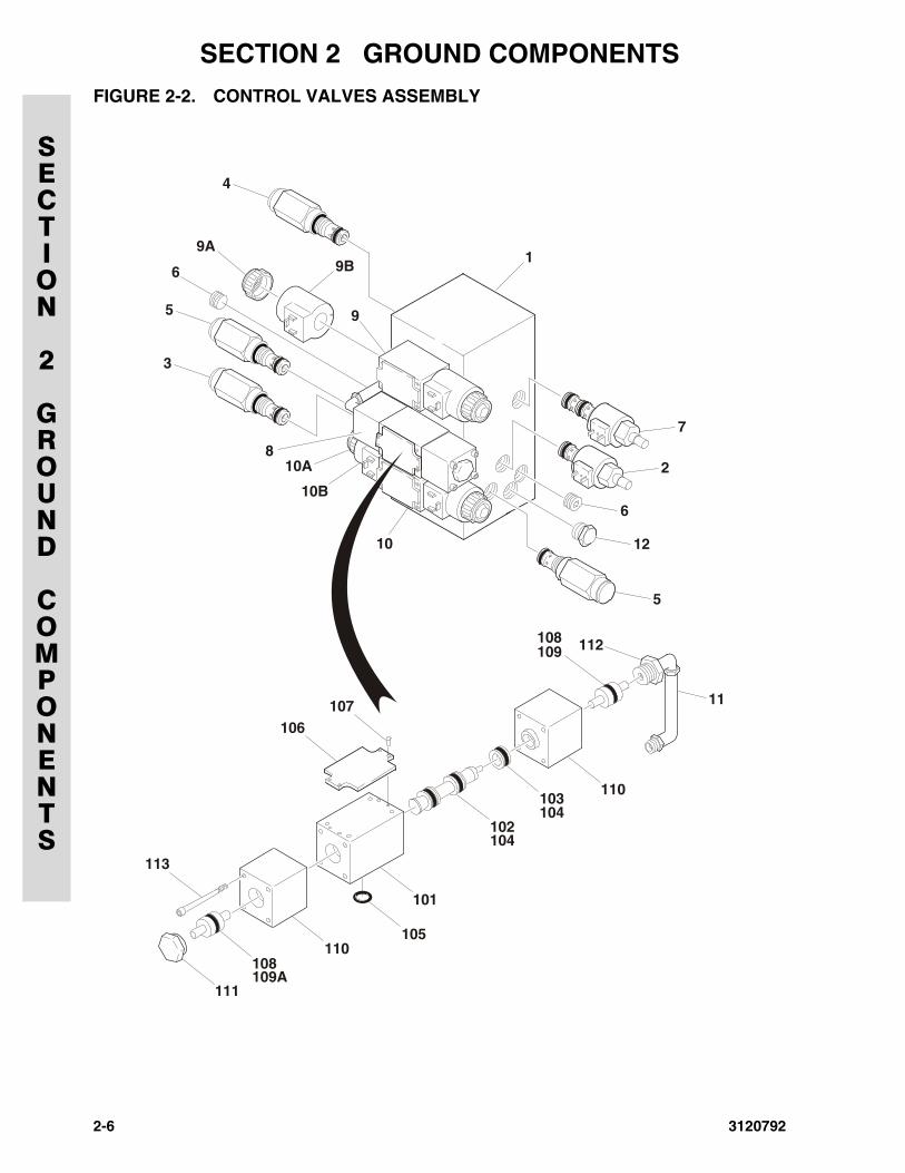
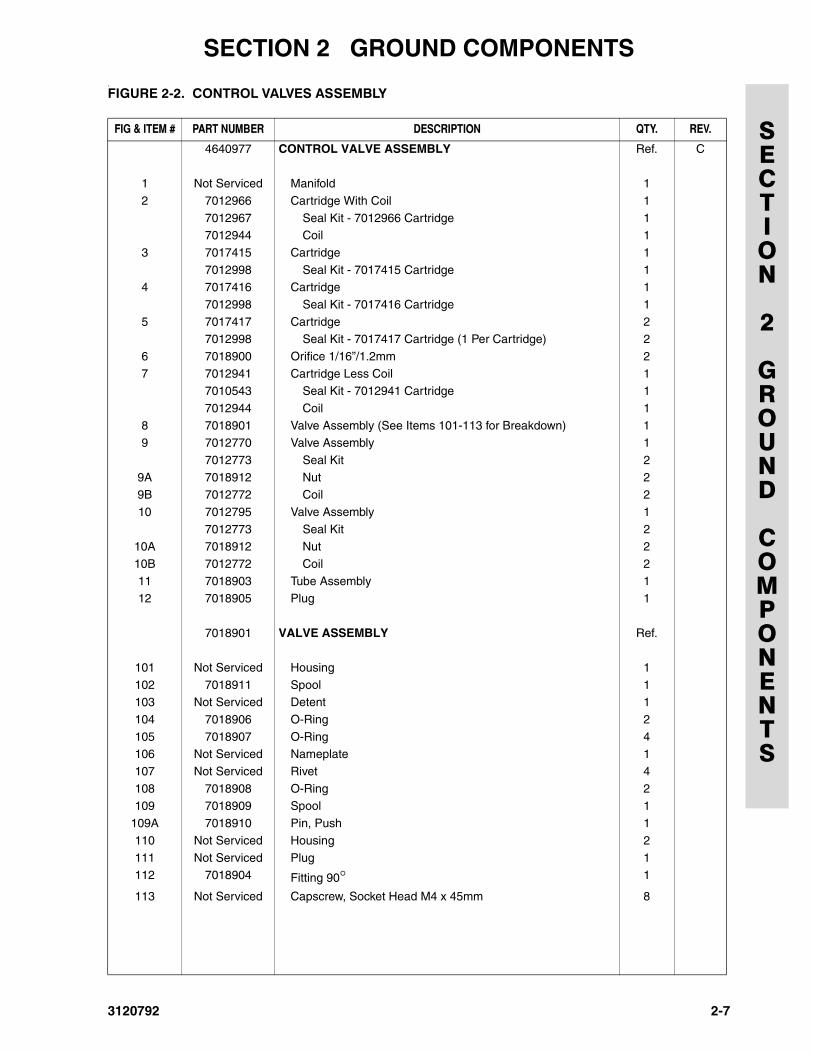
FIGURE 2-2. CONTROL VALVES ASSEMBLY
1
2
6
5
111
113
106107
108109A
110
101
105
102104
103104
110
108109
11
112
12
10A
10B
10
8
3
5
6
4
9A
9
9B
7
2-6 3120792
SECTION 2 GROUND COMPONENTS
SECTION
2
GROUND
COMPONENTS
.FIGURE 2-2. CONTROL VALVES ASSEMBLY
FIG & ITEM # PART NUMBER DESCRIPTION QTY. REV.
4640977 CONTROL VALVE ASSEMBLY Ref. C
1 Not Serviced Manifold 1
2 7012966 Cartridge With Coil 1
7012967 Seal Kit - 7012966 Cartridge 17012944 Coil 1
3 7017415 Cartridge 1
7012998 Seal Kit - 7017415 Cartridge 14 7017416 Cartridge 1
7012998 Seal Kit - 7017416 Cartridge 1
5 7017417 Cartridge 27012998 Seal Kit - 7017417 Cartridge (1 Per Cartridge) 2
6 7018900 Orifice 1/16”/1.2mm 2
7 7012941 Cartridge Less Coil 17010543 Seal Kit - 7012941 Cartridge 1
7012944 Coil 1
8 7018901 Valve Assembly (See Items 101-113 for Breakdown) 19 7012770 Valve Assembly 1
7012773 Seal Kit 2
9A 7018912 Nut 29B 7012772 Coil 2
10 7012795 Valve Assembly 1
7012773 Seal Kit 210A 7018912 Nut 2
10B 7012772 Coil 2
11 7018903 Tube Assembly 112 7018905 Plug 1
7018901 VALVE ASSEMBLY Ref.
101 Not Serviced Housing 1
102 7018911 Spool 1103 Not Serviced Detent 1
104 7018906 O-Ring 2
105 7018907 O-Ring 4106 Not Serviced Nameplate 1
107 Not Serviced Rivet 4
108 7018908 O-Ring 2109 7018909 Spool 1
109A 7018910 Pin, Push 1
110 Not Serviced Housing 2
111 Not Serviced Plug 1112 7018904 Fitting 90° 1
113 Not Serviced Capscrew, Socket Head M4 x 45mm 8
3120792 2-7
SECTION 2 GROUND COMPONENTS
SECTION
2
GROUND
COMPONENTS
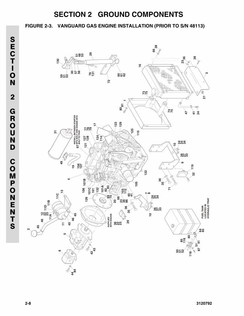
FIGURE 2-3. VANGUARD GAS ENGINE INSTALLATION (PRIOR TO S/N 48113)
17
101B
101C
101
101A 83
82
103
126
112
105
31
49
4
121
114
124
127
128
104
106
107
67IN
STA
LL
BE
TW
EE
N S
TAR
TE
RM
TG
BO
LT A
ND
EN
GIN
E M
TG
BO
LT T
O T
RA
Y
7
9
50
64
40
71
122
51
65F
UE
L T
AN
KL
OC
AT
ED
IN
HY
DR
AU
LIC
TR
AY
41
5285
118
116
11512
5
810
10
2940
119
11 45
4546
11B
11C
19
13
11D
11A12 22 23
24
24
36
41
26
26
2068 25
25
22
27
27
35
35
32
23
34
34
23
33
33
36
36
2
123
129
1
131
8081
6638
16
4774
73
41
75
75
24
3
39
21
3623
77 78 79
5
6
44
42
84
43
SU
PP
LIE
DW
ITH
EN
GIN
E
76
72
5630
130
29
5751 48 53
59 51 53 60 61 62
69 70
132
4546
36 86
5187
2-8 3120792
SECTION 2 GROUND COMPONENTS
SECTION
2
GROUND
COMPONENTS
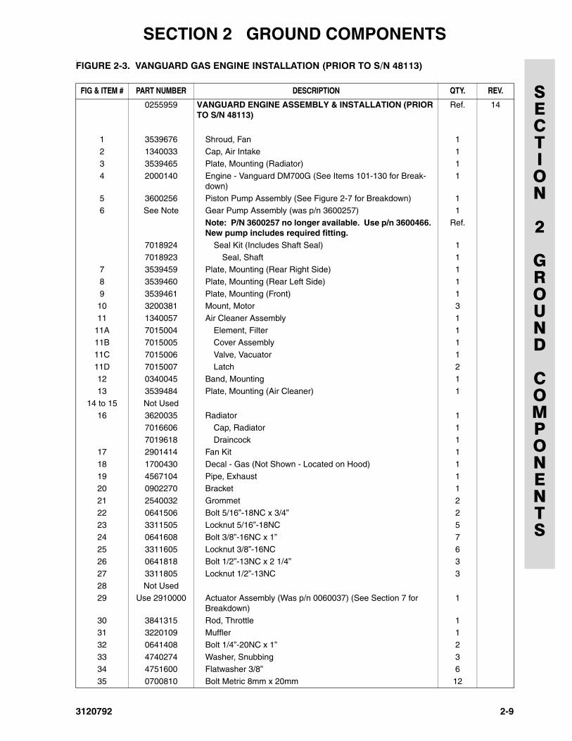
.FIGURE 2-3. VANGUARD GAS ENGINE INSTALLATION (PRIOR TO S/N 48113)
FIG & ITEM # PART NUMBER DESCRIPTION QTY. REV.
0255959 VANGUARD ENGINE ASSEMBLY & INSTALLATION (PRIOR TO S/N 48113)
Ref. 14
1 3539676 Shroud, Fan 12 1340033 Cap, Air Intake 1
3 3539465 Plate, Mounting (Radiator) 1
4 2000140 Engine - Vanguard DM700G (See Items 101-130 for Break-down)
1
5 3600256 Piston Pump Assembly (See Figure 2-7 for Breakdown) 16 See Note Gear Pump Assembly (was p/n 3600257) 1
Note: P/N 3600257 no longer available. Use p/n 3600466. New pump includes required fitting.
Ref.
7018924 Seal Kit (Includes Shaft Seal) 1
7018923 Seal, Shaft 17 3539459 Plate, Mounting (Rear Right Side) 1
8 3539460 Plate, Mounting (Rear Left Side) 1
9 3539461 Plate, Mounting (Front) 110 3200381 Mount, Motor 3
11 1340057 Air Cleaner Assembly 1
11A 7015004 Element, Filter 111B 7015005 Cover Assembly 1
11C 7015006 Valve, Vacuator 1
11D 7015007 Latch 212 0340045 Band, Mounting 1
13 3539484 Plate, Mounting (Air Cleaner) 1
14 to 15 Not Used16 3620035 Radiator 1
7016606 Cap, Radiator 1
7019618 Draincock 117 2901414 Fan Kit 1
18 1700430 Decal - Gas (Not Shown - Located on Hood) 1
19 4567104 Pipe, Exhaust 120 0902270 Bracket 1
21 2540032 Grommet 2
22 0641506 Bolt 5/16”-18NC x 3/4” 223 3311505 Locknut 5/16”-18NC 5
24 0641608 Bolt 3/8”-16NC x 1” 7
25 3311605 Locknut 3/8”-16NC 626 0641818 Bolt 1/2”-13NC x 2 1/4” 3
27 3311805 Locknut 1/2”-13NC 3
28 Not Used29 Use 2910000 Actuator Assembly (Was p/n 0060037) (See Section 7 for
Breakdown)1
30 3841315 Rod, Throttle 131 3220109 Muffler 1
32 0641408 Bolt 1/4”-20NC x 1” 2
33 4740274 Washer, Snubbing 334 4751600 Flatwasher 3/8” 6
35 0700810 Bolt Metric 8mm x 20mm 12
3120792 2-9
SECTION 2 GROUND COMPONENTS
SECTION
2
GROUND
COMPONENTS
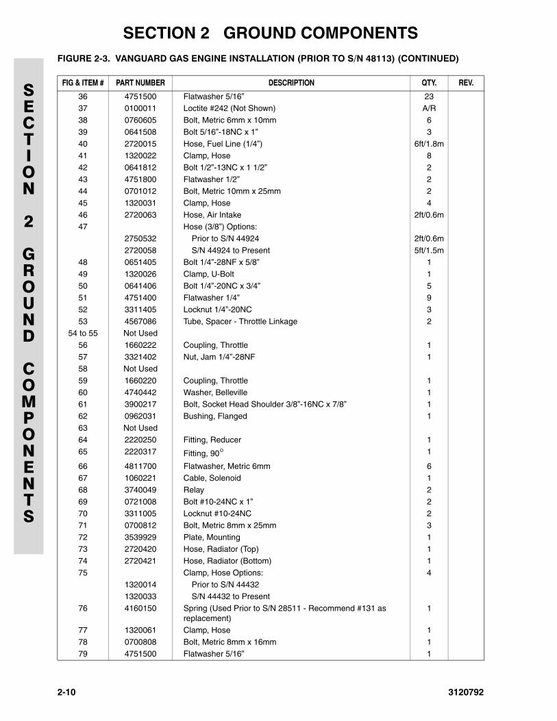
36 4751500 Flatwasher 5/16” 2337 0100011 Loctite #242 (Not Shown) A/R
38 0760605 Bolt, Metric 6mm x 10mm 6
39 0641508 Bolt 5/16”-18NC x 1” 3
40 2720015 Hose, Fuel Line (1/4”) 6ft/1.8m41 1320022 Clamp, Hose 8
42 0641812 Bolt 1/2”-13NC x 1 1/2” 2
43 4751800 Flatwasher 1/2” 244 0701012 Bolt, Metric 10mm x 25mm 2
45 1320031 Clamp, Hose 4
46 2720063 Hose, Air Intake 2ft/0.6m47 Hose (3/8”) Options:
2750532 Prior to S/N 44924 2ft/0.6m
2720058 S/N 44924 to Present 5ft/1.5m48 0651405 Bolt 1/4”-28NF x 5/8” 1
49 1320026 Clamp, U-Bolt 1
50 0641406 Bolt 1/4”-20NC x 3/4” 551 4751400 Flatwasher 1/4” 9
52 3311405 Locknut 1/4”-20NC 3
53 4567086 Tube, Spacer - Throttle Linkage 254 to 55 Not Used
56 1660222 Coupling, Throttle 1
57 3321402 Nut, Jam 1/4”-28NF 158 Not Used
59 1660220 Coupling, Throttle 1
60 4740442 Washer, Belleville 161 3900217 Bolt, Socket Head Shoulder 3/8”-16NC x 7/8” 1
62 0962031 Bushing, Flanged 1
63 Not Used64 2220250 Fitting, Reducer 1
65 2220317 Fitting, 90° 1
66 4811700 Flatwasher, Metric 6mm 667 1060221 Cable, Solenoid 1
68 3740049 Relay 2
69 0721008 Bolt #10-24NC x 1” 270 3311005 Locknut #10-24NC 2
71 0700812 Bolt, Metric 8mm x 25mm 3
72 3539929 Plate, Mounting 173 2720420 Hose, Radiator (Top) 1
74 2720421 Hose, Radiator (Bottom) 1
75 Clamp, Hose Options: 4
1320014 Prior to S/N 444321320033 S/N 44432 to Present
76 4160150 Spring (Used Prior to S/N 28511 - Recommend #131 as replacement)
1
77 1320061 Clamp, Hose 1
78 0700808 Bolt, Metric 8mm x 16mm 179 4751500 Flatwasher 5/16” 1
FIGURE 2-3. VANGUARD GAS ENGINE INSTALLATION (PRIOR TO S/N 48113) (CONTINUED)
FIG & ITEM # PART NUMBER DESCRIPTION QTY. REV.
2-10 3120792
SECTION 2 GROUND COMPONENTS
SECTION
2
GROUND
COMPONENTS
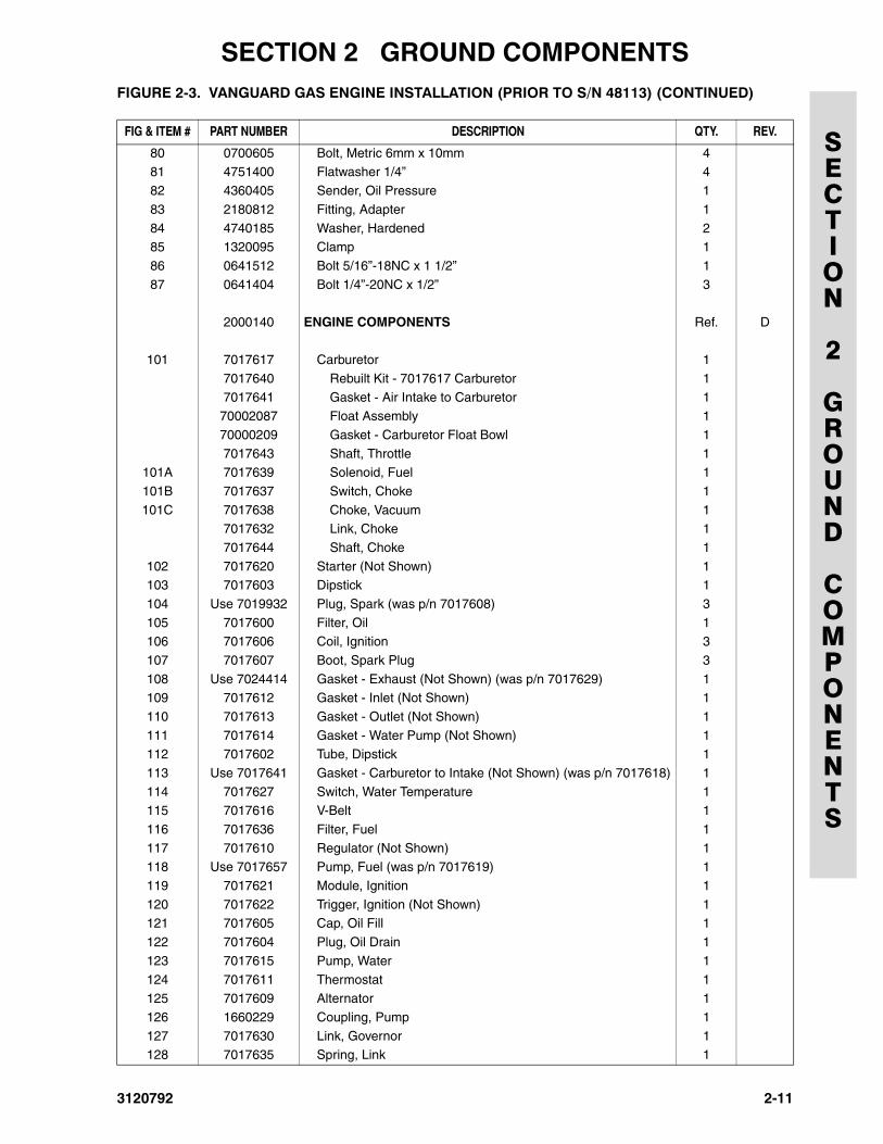
80 0700605 Bolt, Metric 6mm x 10mm 481 4751400 Flatwasher 1/4” 4
82 4360405 Sender, Oil Pressure 1
83 2180812 Fitting, Adapter 1
84 4740185 Washer, Hardened 285 1320095 Clamp 1
86 0641512 Bolt 5/16”-18NC x 1 1/2” 1
87 0641404 Bolt 1/4”-20NC x 1/2” 3
2000140 ENGINE COMPONENTS Ref. D
101 7017617 Carburetor 1
7017640 Rebuilt Kit - 7017617 Carburetor 1
7017641 Gasket - Air Intake to Carburetor 170002087 Float Assembly 1
70000209 Gasket - Carburetor Float Bowl 1
7017643 Shaft, Throttle 1101A 7017639 Solenoid, Fuel 1
101B 7017637 Switch, Choke 1
101C 7017638 Choke, Vacuum 17017632 Link, Choke 1
7017644 Shaft, Choke 1
102 7017620 Starter (Not Shown) 1103 7017603 Dipstick 1
104 Use 7019932 Plug, Spark (was p/n 7017608) 3
105 7017600 Filter, Oil 1106 7017606 Coil, Ignition 3
107 7017607 Boot, Spark Plug 3
108 Use 7024414 Gasket - Exhaust (Not Shown) (was p/n 7017629) 1109 7017612 Gasket - Inlet (Not Shown) 1
110 7017613 Gasket - Outlet (Not Shown) 1
111 7017614 Gasket - Water Pump (Not Shown) 1112 7017602 Tube, Dipstick 1
113 Use 7017641 Gasket - Carburetor to Intake (Not Shown) (was p/n 7017618) 1
114 7017627 Switch, Water Temperature 1115 7017616 V-Belt 1
116 7017636 Filter, Fuel 1
117 7017610 Regulator (Not Shown) 1118 Use 7017657 Pump, Fuel (was p/n 7017619) 1
119 7017621 Module, Ignition 1
120 7017622 Trigger, Ignition (Not Shown) 1121 7017605 Cap, Oil Fill 1
122 7017604 Plug, Oil Drain 1
123 7017615 Pump, Water 1
124 7017611 Thermostat 1125 7017609 Alternator 1
126 1660229 Coupling, Pump 1
127 7017630 Link, Governor 1128 7017635 Spring, Link 1
FIGURE 2-3. VANGUARD GAS ENGINE INSTALLATION (PRIOR TO S/N 48113) (CONTINUED)
FIG & ITEM # PART NUMBER DESCRIPTION QTY. REV.
3120792 2-11
SECTION 2 GROUND COMPONENTS
SECTION
2
GROUND
COMPONENTS
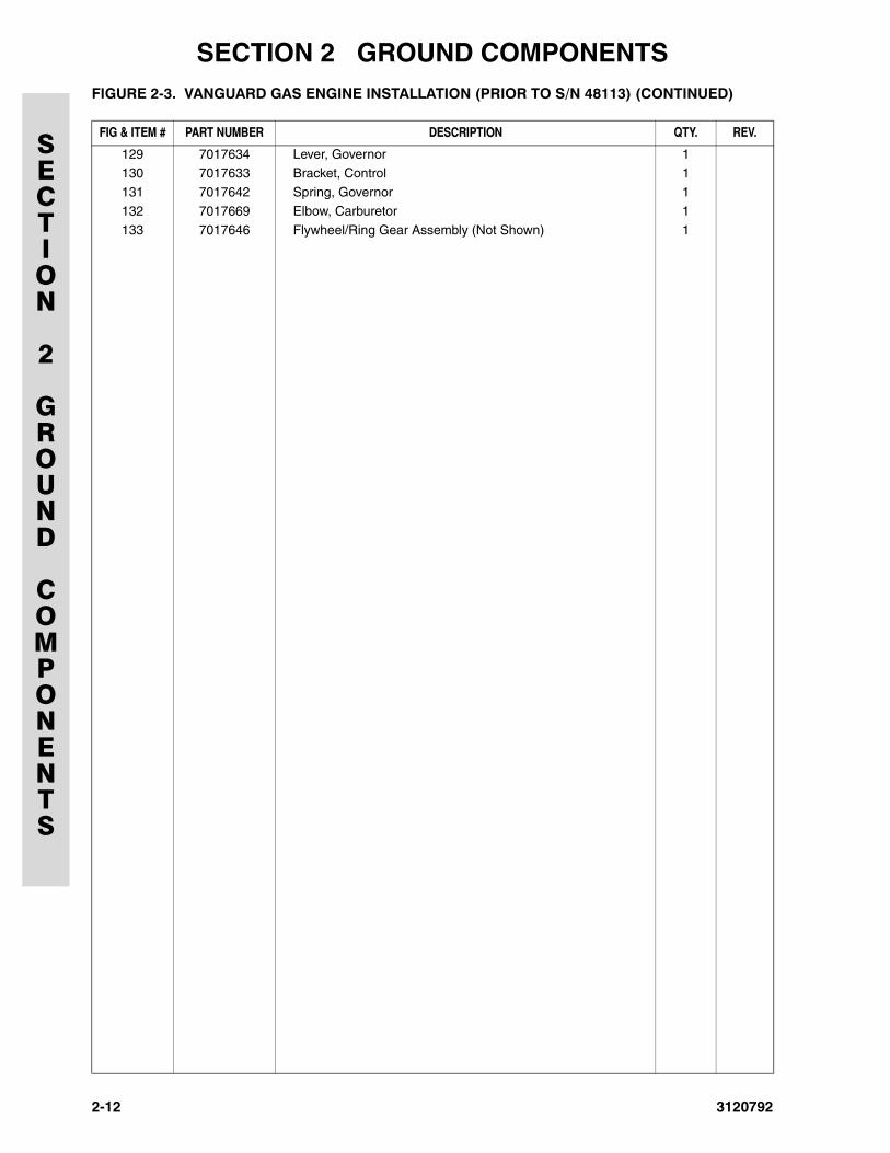
129 7017634 Lever, Governor 1130 7017633 Bracket, Control 1
131 7017642 Spring, Governor 1
132 7017669 Elbow, Carburetor 1
133 7017646 Flywheel/Ring Gear Assembly (Not Shown) 1
FIGURE 2-3. VANGUARD GAS ENGINE INSTALLATION (PRIOR TO S/N 48113) (CONTINUED)
FIG & ITEM # PART NUMBER DESCRIPTION QTY. REV.
2-12 3120792
SECTION 2 GROUND COMPONENTS
SECTION
2
GROUND
COMPONENTS
FIGURE 2-3. VANGUARD GAS ENGINE INSTALLATION (PRIOR TO S/N 48113) (CONTINUED)
FIG & ITEM # PART NUMBER DESCRIPTION QTY. REV.
3120792 2-13
SECTION 2 GROUND COMPONENTS
SECTION
2
GROUND
COMPONENTS
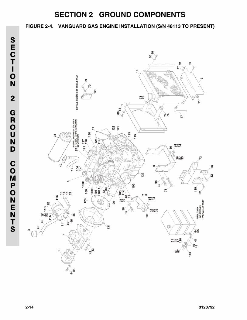
FIGURE 2-4. VANGUARD GAS ENGINE INSTALLATION (S/N 48113 TO PRESENT)
17
101B
101C
101
101A 83
82
103
126
112
105
31
49
4
121
114
124
130
127
128
104
106
107
67IN
STA
LL
BE
TW
EE
N S
TAR
TE
RM
TG
BO
LT A
ND
EN
GIN
E M
TG
BO
LT T
O T
RA
YIN
STA
LL
ON
BA
CK
OF
EN
GIN
E T
RA
Y
7
9
6440
71
122
51
65F
UE
L T
AN
KL
OC
AT
ED
IN
HY
DR
AU
LIC
TR
AY
4141
87878551
118
116
11512
5
810
10
40
119
11 45
4546
11B
11C
19
13 14 15 22
11D
11A12 22 23
24
24
41
26
26
20
25
25
27
27
35
35
32
3268
72
35 36
34
34
33
33
36
36
2
123
123
129
180
81
6680
16
4774
73
75
75
3
39
21
7923
5
6
44
4269
84
437 0
129
131
4546
2-14 3120792
SECTION 2 GROUND COMPONENTS
SECTION
2
GROUND
COMPONENTS
.FIGURE 2-4. VANGUARD GAS ENGINE INSTALLATION (S/N 48113 TO PRESENT)
FIG & ITEM # PART NUMBER DESCRIPTION QTY. REV.
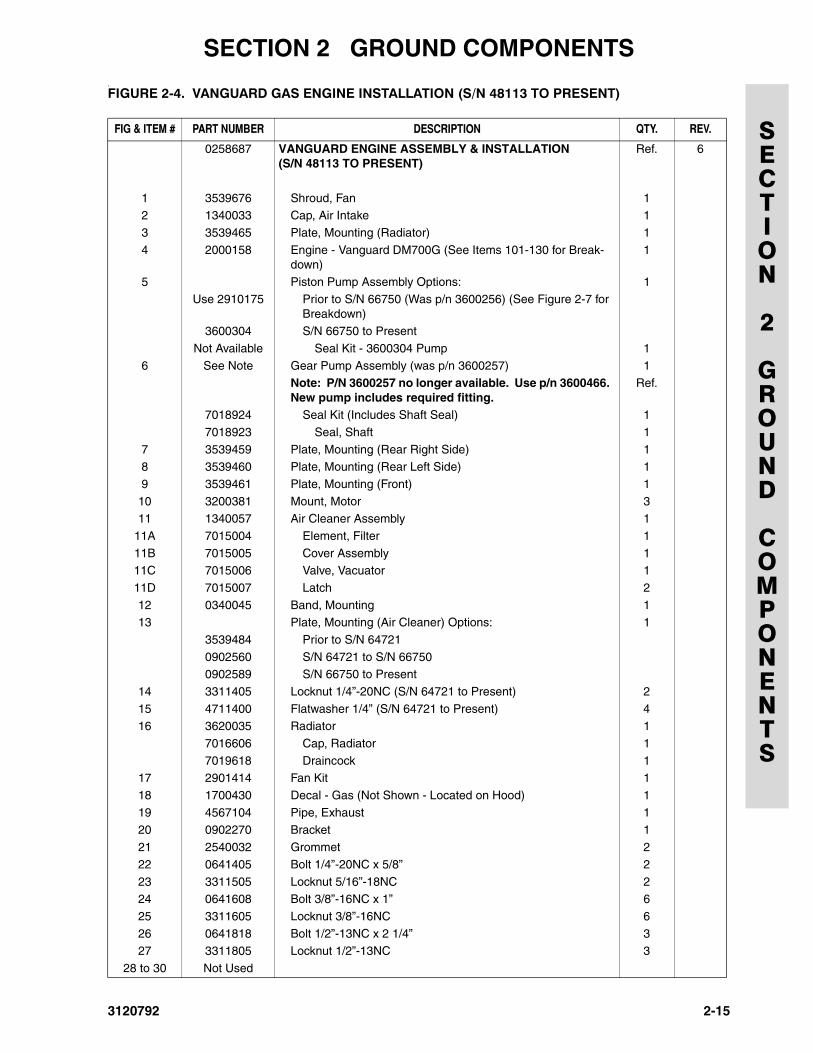
0258687 VANGUARD ENGINE ASSEMBLY & INSTALLATION (S/N 48113 TO PRESENT)
Ref. 6
1 3539676 Shroud, Fan 12 1340033 Cap, Air Intake 1
3 3539465 Plate, Mounting (Radiator) 1
4 2000158 Engine - Vanguard DM700G (See Items 101-130 for Break-down)
1
5 Piston Pump Assembly Options: 1Use 2910175 Prior to S/N 66750 (Was p/n 3600256) (See Figure 2-7 for
Breakdown)3600304 S/N 66750 to Present
Not Available Seal Kit - 3600304 Pump 1
6 See Note Gear Pump Assembly (was p/n 3600257) 1Note: P/N 3600257 no longer available. Use p/n 3600466. New pump includes required fitting.
Ref.
7018924 Seal Kit (Includes Shaft Seal) 1
7018923 Seal, Shaft 1
7 3539459 Plate, Mounting (Rear Right Side) 18 3539460 Plate, Mounting (Rear Left Side) 1
9 3539461 Plate, Mounting (Front) 1
10 3200381 Mount, Motor 311 1340057 Air Cleaner Assembly 1
11A 7015004 Element, Filter 1
11B 7015005 Cover Assembly 111C 7015006 Valve, Vacuator 1
11D 7015007 Latch 2
12 0340045 Band, Mounting 113 Plate, Mounting (Air Cleaner) Options: 1
3539484 Prior to S/N 64721
0902560 S/N 64721 to S/N 667500902589 S/N 66750 to Present
14 3311405 Locknut 1/4”-20NC (S/N 64721 to Present) 2
15 4711400 Flatwasher 1/4” (S/N 64721 to Present) 416 3620035 Radiator 1
7016606 Cap, Radiator 1
7019618 Draincock 117 2901414 Fan Kit 1
18 1700430 Decal - Gas (Not Shown - Located on Hood) 1
19 4567104 Pipe, Exhaust 120 0902270 Bracket 1
21 2540032 Grommet 2
22 0641405 Bolt 1/4”-20NC x 5/8” 2
23 3311505 Locknut 5/16”-18NC 224 0641608 Bolt 3/8”-16NC x 1” 6
25 3311605 Locknut 3/8”-16NC 6
26 0641818 Bolt 1/2”-13NC x 2 1/4” 327 3311805 Locknut 1/2”-13NC 3
28 to 30 Not Used
3120792 2-15
SECTION 2 GROUND COMPONENTS
SECTION
2
GROUND
COMPONENTS
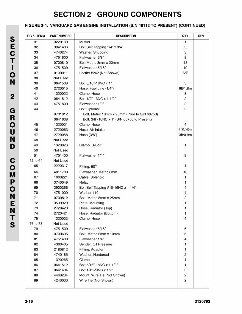
31 3220109 Muffler 132 3941406 Bolt Self Tapping 1/4” x 3/4” 3
33 4740274 Washer, Snubbing 3
34 4751600 Flatwasher 3/8” 8
35 0700810 Bolt Metric 8mm x 20mm 1336 4751500 Flatwasher 5/16” 19
37 0100011 Loctite #242 (Not Shown) A/R
38 Not Used39 0641508 Bolt 5/16”-18NC x 1” 3
40 2720015 Hose, Fuel Line (1/4”) 6ft/1.8m
41 1320022 Clamp, Hose 842 0641812 Bolt 1/2”-13NC x 1 1/2” 2
43 4751800 Flatwasher 1/2” 2
44 Bolt Options: 20701012 Bolt, Metric 10mm x 25mm (Prior to S/N 66750)
0641608 Bolt, 3/8”-16NC x 1” (S/N 66750 to Present)
45 1320031 Clamp, Hose 446 2720063 Hose, Air Intake 1.3ft/.40m
47 2720058 Hose (3/8”) 3ft/0.9m
48 Not Used49 1320026 Clamp, U-Bolt 1
50 Not Used
51 4751400 Flatwasher 1/4” 952 to 64 Not Used
65 2220317 Fitting, 90° 1
66 4811700 Flatwasher, Metric 6mm 1067 1060221 Cable, Solenoid 1
68 3740049 Relay 1
69 3900256 Bolt Self Tapping #10-16NC x 1 1/4” 470 4751000 Washer #10 4
71 0700812 Bolt, Metric 8mm x 25mm 2
72 3539929 Plate, Mounting 173 2720420 Hose, Radiator (Top) 1
74 2720421 Hose, Radiator (Bottom) 1
75 1320033 Clamp, Hose 476 to 78 Not Used
79 4751500 Flatwasher 5/16” 6
80 0700605 Bolt, Metric 6mm x 10mm 681 4751400 Flatwasher 1/4” 4
82 4360405 Sender, Oil Pressure 1
83 2180812 Fitting, Adapter 1
84 4740185 Washer, Hardened 285 1320265 Clamp 1
86 0641512 Bolt 5/16”-18NC x 1 1/2” 1
87 0641404 Bolt 1/4”-20NC x 1/2” 388 4460234 Mount, Wire Tie (Not Shown) 2
89 4240033 Wire Tie (Not Shown) 2
FIGURE 2-4. VANGUARD GAS ENGINE INSTALLATION (S/N 48113 TO PRESENT) (CONTINUED)
FIG & ITEM # PART NUMBER DESCRIPTION QTY. REV.
2-16 3120792
SECTION 2 GROUND COMPONENTS
SECTION
2
GROUND
COMPONENTS
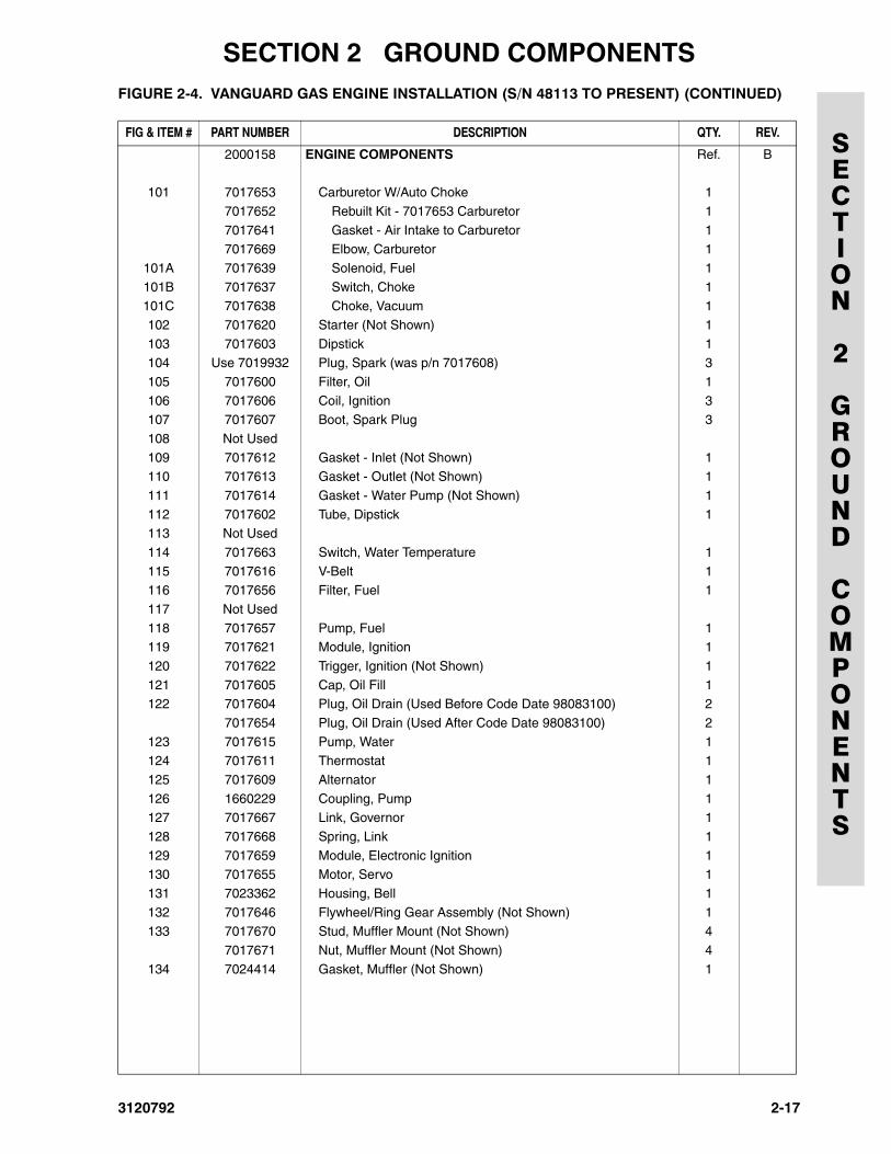
2000158 ENGINE COMPONENTS Ref. B
101 7017653 Carburetor W/Auto Choke 1
7017652 Rebuilt Kit - 7017653 Carburetor 1
7017641 Gasket - Air Intake to Carburetor 17017669 Elbow, Carburetor 1
101A 7017639 Solenoid, Fuel 1
101B 7017637 Switch, Choke 1101C 7017638 Choke, Vacuum 1
102 7017620 Starter (Not Shown) 1
103 7017603 Dipstick 1104 Use 7019932 Plug, Spark (was p/n 7017608) 3
105 7017600 Filter, Oil 1
106 7017606 Coil, Ignition 3107 7017607 Boot, Spark Plug 3
108 Not Used
109 7017612 Gasket - Inlet (Not Shown) 1110 7017613 Gasket - Outlet (Not Shown) 1
111 7017614 Gasket - Water Pump (Not Shown) 1
112 7017602 Tube, Dipstick 1113 Not Used
114 7017663 Switch, Water Temperature 1
115 7017616 V-Belt 1116 7017656 Filter, Fuel 1
117 Not Used
118 7017657 Pump, Fuel 1119 7017621 Module, Ignition 1
120 7017622 Trigger, Ignition (Not Shown) 1
121 7017605 Cap, Oil Fill 1122 7017604 Plug, Oil Drain (Used Before Code Date 98083100) 2
7017654 Plug, Oil Drain (Used After Code Date 98083100) 2
123 7017615 Pump, Water 1124 7017611 Thermostat 1
125 7017609 Alternator 1
126 1660229 Coupling, Pump 1127 7017667 Link, Governor 1
128 7017668 Spring, Link 1
129 7017659 Module, Electronic Ignition 1130 7017655 Motor, Servo 1
131 7023362 Housing, Bell 1
132 7017646 Flywheel/Ring Gear Assembly (Not Shown) 1133 7017670 Stud, Muffler Mount (Not Shown) 4
7017671 Nut, Muffler Mount (Not Shown) 4
134 7024414 Gasket, Muffler (Not Shown) 1
FIGURE 2-4. VANGUARD GAS ENGINE INSTALLATION (S/N 48113 TO PRESENT) (CONTINUED)
FIG & ITEM # PART NUMBER DESCRIPTION QTY. REV.
3120792 2-17
SECTION 2 GROUND COMPONENTS
SECTION
2
GROUND
COMPONENTS
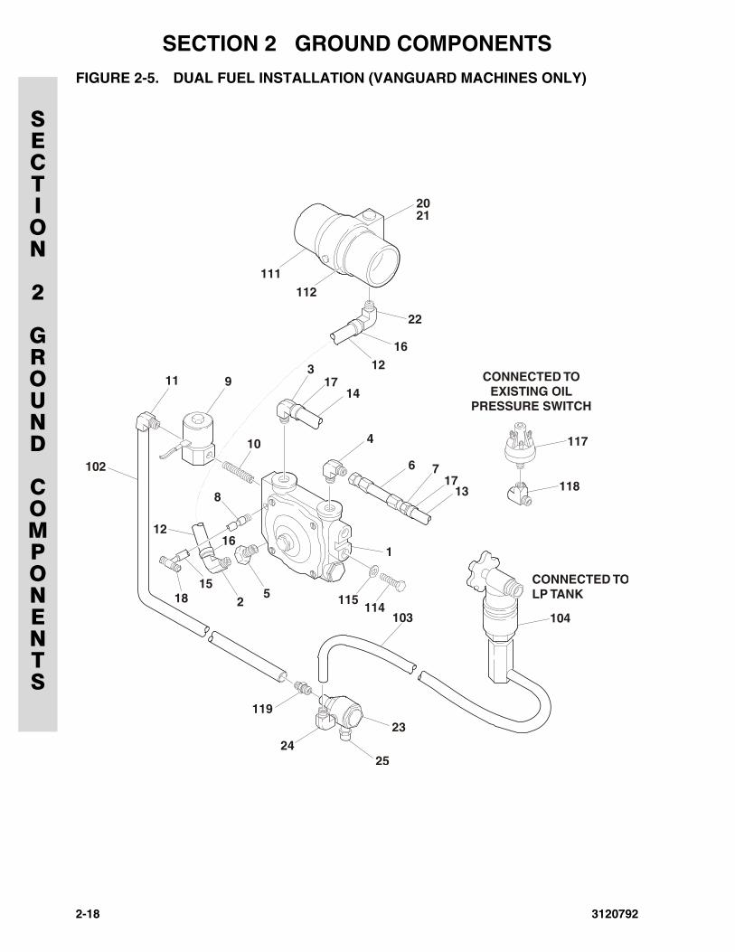
FIGURE 2-5. DUAL FUEL INSTALLATION (VANGUARD MACHINES ONLY)
1
103
23
2524
119
104
117
118
3911
10 4
6
8
1216
1216
22
2021
111
102
112
1518
717
13
CONNECTED TOLP TANK
CONNECTED TOEXISTING OIL
PRESSURE SWITCH14
17
25
114115
2-18 3120792
SECTION 2 GROUND COMPONENTS
SECTION
2
GROUND
COMPONENTS
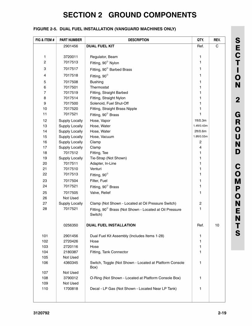
.FIGURE 2-5. DUAL FUEL INSTALLATION (VANGUARD MACHINES ONLY)
FIG & ITEM # PART NUMBER DESCRIPTION QTY. REV.
2901456 DUAL FUEL KIT Ref. C
1 3720011 Regulator, Beam 1
2 7017513 Fitting, 90° Nylon 1
3 7017517 Fitting, 90° Barbed Brass 1
4 7017518 Fitting, 90° 1
5 7017508 Bushing 1
6 7017501 Thermostat 17 7017519 Fitting, Straight Barbed 1
8 7017514 Fitting, Straight Nylon 1
9 7017500 Solenoid, Fuel Shut-Off 110 7017520 Fitting, Straight Brass Nipple 1
11 7017521 Fitting, 90° Brass 1
12 Supply Locally Hose, Vapor 1ft/0.3m
13 Supply Locally Hose, Water 1.4ft/0.43m
14 Supply Locally Hose, Water 2ft/0.6m
15 Supply Locally Hose, Vacuum 1.8ft/0.55m
16 Supply Locally Clamp 2
17 Supply Locally Clamp 4
18 7017512 Fitting, Tee 119 Supply Locally Tie-Strap (Not Shown) 1
20 7017511 Adapter, In-Line 1
21 7017510 Venturi 122 7017513 Fitting, 90° 1
23 7017504 Filter, Fuel 1
24 7017521 Fitting, 90° Brass 1
25 7017505 Valve, Relief 1
26 Not Used
27 Supply Locally Clamp (Not Shown - Located at Oil Pressure Switch) 228 7017521 Fitting, 90° Brass (Not Shown - Located at Oil Pressure
Switch)
1
0256350 DUAL FUEL INSTALLATION Ref. 10
101 2901456 Dual Fuel Kit Assembly (Includes Items 1-28) 1
102 2720426 Hose 1
103 2720116 Hose 1104 2180387 Fitting, Tank Connector 1
105 Not Used
106 4360345 Switch, Toggle (Not Shown - Located at Platform Console Box)
1
107 Not Used
108 3790012 O-Ring (Not Shown - Located at Platform Console Box) 1109 Not Used
110 1700818 Decal - LP Gas (Not Shown - Located Near LP Tank) 1
3120792 2-19
SECTION 2 GROUND COMPONENTS
SECTION
2
GROUND
COMPONENTS
111 Hose, Radiator Options: 22720433 Prior to S/N 43783
2720444 S/N 43783 to Present
112 1320016 Clamp 2
113 Not Used114 0641405 Bolt 1/4”-20NC x 5/8” 2
115 4711400 Flatwasher 1/4” 2
116 0100011 Loctite #242 (Not Shown) A/R117 4360357 Switch, Oil Pressure (S/N 29981 to Present) 1
118 2180360 Fitting, Tee (S/N 29981 to Present) 1
119 2180418 Fitting (S/N 43783 to Present) 1
FIGURE 2-5. DUAL FUEL INSTALLATION (VANGUARD MACHINES ONLY) (CONTINUED)
FIG & ITEM # PART NUMBER DESCRIPTION QTY. REV.
2-20 3120792
SECTION 2 GROUND COMPONENTS
SECTION
2
GROUND
COMPONENTS
FIGURE 2-5. DUAL FUEL INSTALLATION (VANGUARD MACHINES ONLY) (CONTINUED)
FIG & ITEM # PART NUMBER DESCRIPTION QTY. REV.
3120792 2-21
SECTION 2 GROUND COMPONENTS
SECTION
2
GROUND
COMPONENTS
2-22 3120792
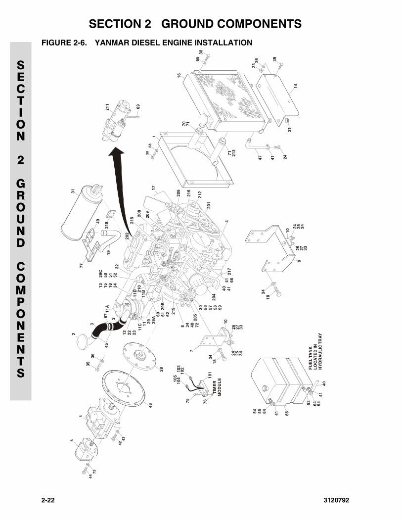
FIGURE 2-6. YANMAR DIESEL ENGINE INSTALLATION
168
38
26 27 33
6838
16
14
39
21
3623
69
10
10
18
26 27 339
24
24
25
25
34
34
3447 41 24
31
49
77 32
19
TIM
ER
MO
DU
LE
28
5
6
44
4243
73
67
12 22 2311
C 1111
B
11D
8 34 48 72
3536
40 41
205
216
201
71
7170
213
206
215 20
8
1720
9
204
210
11A
3
3
45
2
7
FU
EL
TA
NK
LO
CA
TE
D IN
H
YD
RA
UL
IC T
RA
Y40
4164 6553
41 6654 55 64
29 29A
29C
50 51 52
29B
30 56 57 58 5918
10110
210
410
310
5
34
75 76
41 66
13 15 18 34
211
202
212
4
60 61 62
217
218
219
48
SECTION 2 GROUND COMPONENTS
SECTION
2
GROUND
COMPONENTS
.FIGURE 2-6. YANMAR DIESEL ENGINE INSTALLATION
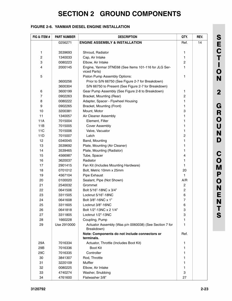
FIG & ITEM # PART NUMBER DESCRIPTION QTY. REV.
0256271 ENGINE ASSEMBLY & INSTALLATION Ref. 14
1 3539693 Shroud, Radiator 1
2 1340033 Cap, Air Intake 1
3 0080223 Elbow, Air Intake 24 2000145 Engine, Yanmar 3TNE68 (See Items 101-116 for JLG Ser-
viced Parts)1
5 Piston Pump Assembly Options: 1
3600256 Prior to S/N 66750 (See Figure 2-7 for Breakdown)
3600304 S/N 66750 to Present (See Figure 2-7 for Breakdown)6 3600199 Gear Pump Assembly (See Figure 2-8 to Breakdown) 1
7 0902263 Bracket, Mounting (Rear) 2
8 0080222 Adapter, Spacer - Flywheel Housing 19 0902265 Bracket, Mounting (Front) 1
10 3200381 Mount, Motor 3
11 1340057 Air Cleaner Assembly 111A 7015004 Element, Filter 1
11B 7015005 Cover Assembly 1
11C 7015006 Valve, Vacuator 111D 7015007 Latch 2
12 0340045 Band, Mounting 1
13 3539692 Plate, Mounting (Air Cleaner) 114 3539465 Plate, Mounting (Radiator) 1
15 4566987 Tube, Spacer 4
16 3620037 Radiator 117 2901415 Fan Kit (Includes Mounting Hardware) 1
18 0701012 Bolt, Metric 10mm x 25mm 20
19 4567104 Pipe Exhaust 120 0100020 Sealant, Pipe (Not Shown) A/R
21 2540032 Grommet 2
22 0641506 Bolt 5/16”-18NC x 3/4” 223 3311505 Locknut 5/16”-18NC 6
24 0641608 Bolt 3/8”-16NC x 1” 7
25 3311605 Locknut 3/8”-16NC 626 0641818 Bolt 1/2”-13NC x 2 1/4” 3
27 3311805 Locknut 1/2”-13NC 3
28 1660228 Coupling, Pump 129 Use 2910000 Actuator Assembly (Was p/n 0060038) (See Section 7 for
Breakdown)1
Note: Components do not include connectors or terminals.
Ref.
29A 7016334 Actuator, Throttle (Includes Boot Kit) 1
29B 7016336 Boot Kit 1
29C 7016335 Controller 1
30 3841307 Rod, Throttle 131 3220109 Muffler 1
32 0080225 Elbow, Air Intake 1
33 4740274 Washer, Snubbing 334 4761600 Flatwasher 3/8” 27
3120792 2-23
SECTION 2 GROUND COMPONENTS
SECTION
2
GROUND
COMPONENTS
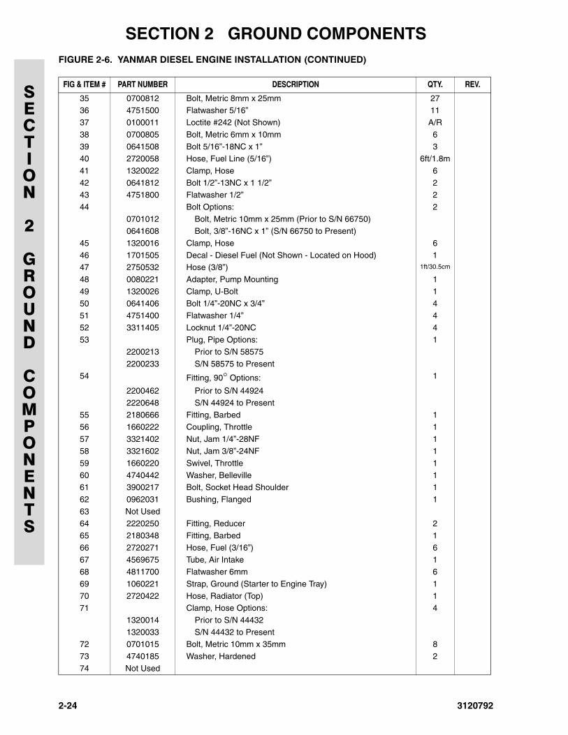
35 0700812 Bolt, Metric 8mm x 25mm 2736 4751500 Flatwasher 5/16” 11
37 0100011 Loctite #242 (Not Shown) A/R
38 0700805 Bolt, Metric 6mm x 10mm 6
39 0641508 Bolt 5/16”-18NC x 1” 340 2720058 Hose, Fuel Line (5/16”) 6ft/1.8m
41 1320022 Clamp, Hose 6
42 0641812 Bolt 1/2”-13NC x 1 1/2” 243 4751800 Flatwasher 1/2” 2
44 Bolt Options: 2
0701012 Bolt, Metric 10mm x 25mm (Prior to S/N 66750)0641608 Bolt, 3/8”-16NC x 1” (S/N 66750 to Present)
45 1320016 Clamp, Hose 6
46 1701505 Decal - Diesel Fuel (Not Shown - Located on Hood) 147 2750532 Hose (3/8”) 1ft/30.5cm
48 0080221 Adapter, Pump Mounting 1
49 1320026 Clamp, U-Bolt 150 0641406 Bolt 1/4”-20NC x 3/4” 4
51 4751400 Flatwasher 1/4” 4
52 3311405 Locknut 1/4”-20NC 453 Plug, Pipe Options: 1
2200213 Prior to S/N 58575
2200233 S/N 58575 to Present54 Fitting, 90° Options: 1
2200462 Prior to S/N 44924
2220648 S/N 44924 to Present55 2180666 Fitting, Barbed 1
56 1660222 Coupling, Throttle 1
57 3321402 Nut, Jam 1/4”-28NF 158 3321602 Nut, Jam 3/8”-24NF 1
59 1660220 Swivel, Throttle 1
60 4740442 Washer, Belleville 161 3900217 Bolt, Socket Head Shoulder 1
62 0962031 Bushing, Flanged 1
63 Not Used64 2220250 Fitting, Reducer 2
65 2180348 Fitting, Barbed 1
66 2720271 Hose, Fuel (3/16”) 667 4569675 Tube, Air Intake 1
68 4811700 Flatwasher 6mm 6
69 1060221 Strap, Ground (Starter to Engine Tray) 1
70 2720422 Hose, Radiator (Top) 171 Clamp, Hose Options: 4
1320014 Prior to S/N 44432
1320033 S/N 44432 to Present72 0701015 Bolt, Metric 10mm x 35mm 8
73 4740185 Washer, Hardened 2
74 Not Used
FIGURE 2-6. YANMAR DIESEL ENGINE INSTALLATION (CONTINUED)
FIG & ITEM # PART NUMBER DESCRIPTION QTY. REV.
2-24 3120792
SECTION 2 GROUND COMPONENTS
SECTION
2
GROUND
COMPONENTS
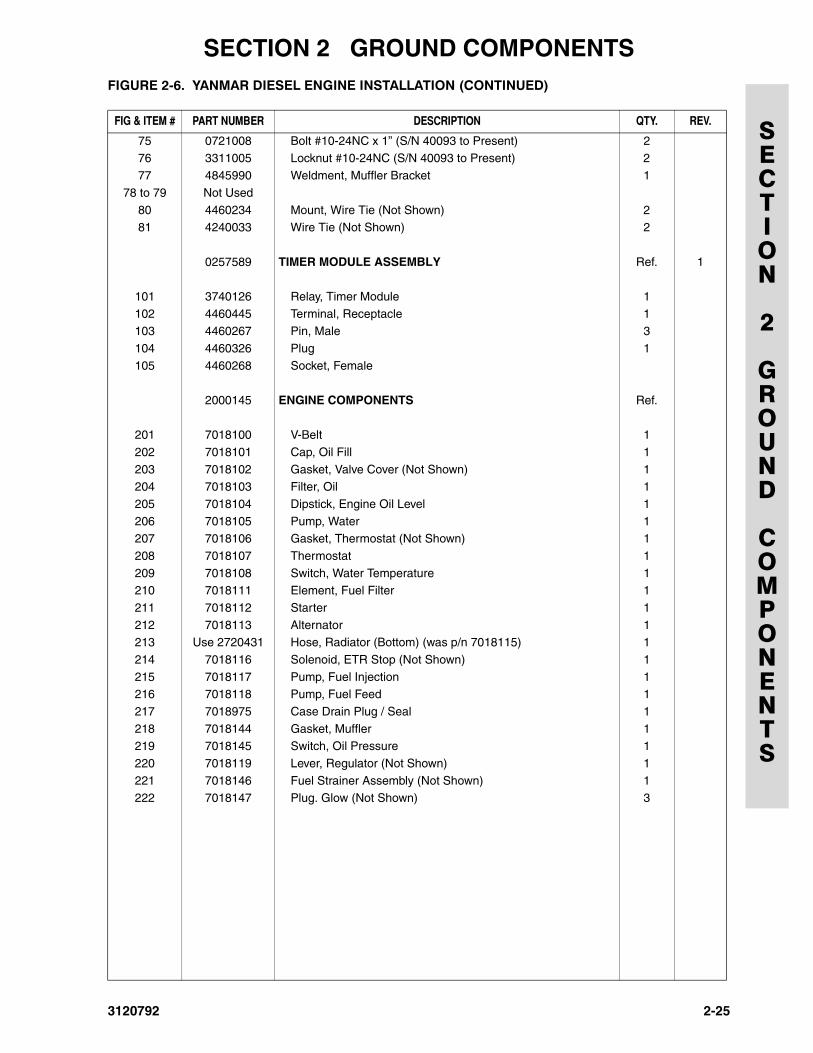
75 0721008 Bolt #10-24NC x 1” (S/N 40093 to Present) 276 3311005 Locknut #10-24NC (S/N 40093 to Present) 2
77 4845990 Weldment, Muffler Bracket 1
78 to 79 Not Used
80 4460234 Mount, Wire Tie (Not Shown) 281 4240033 Wire Tie (Not Shown) 2
0257589 TIMER MODULE ASSEMBLY Ref. 1
101 3740126 Relay, Timer Module 1
102 4460445 Terminal, Receptacle 1103 4460267 Pin, Male 3
104 4460326 Plug 1
105 4460268 Socket, Female
2000145 ENGINE COMPONENTS Ref.
201 7018100 V-Belt 1
202 7018101 Cap, Oil Fill 1
203 7018102 Gasket, Valve Cover (Not Shown) 1204 7018103 Filter, Oil 1
205 7018104 Dipstick, Engine Oil Level 1
206 7018105 Pump, Water 1207 7018106 Gasket, Thermostat (Not Shown) 1
208 7018107 Thermostat 1
209 7018108 Switch, Water Temperature 1210 7018111 Element, Fuel Filter 1
211 7018112 Starter 1
212 7018113 Alternator 1213 Use 2720431 Hose, Radiator (Bottom) (was p/n 7018115) 1
214 7018116 Solenoid, ETR Stop (Not Shown) 1
215 7018117 Pump, Fuel Injection 1216 7018118 Pump, Fuel Feed 1
217 7018975 Case Drain Plug / Seal 1
218 7018144 Gasket, Muffler 1219 7018145 Switch, Oil Pressure 1
220 7018119 Lever, Regulator (Not Shown) 1
221 7018146 Fuel Strainer Assembly (Not Shown) 1222 7018147 Plug. Glow (Not Shown) 3
FIGURE 2-6. YANMAR DIESEL ENGINE INSTALLATION (CONTINUED)
FIG & ITEM # PART NUMBER DESCRIPTION QTY. REV.
3120792 2-25
SECTION 2 GROUND COMPONENTS
SECTION
2
GROUND
COMPONENTS
FIGURE 2-7. PISTON PUMP ASSEMBLY
67
14
1212
14
9
179
1318
8
1
3
110
1110
2
13
15
5
16
19
2-26 3120792
SECTION 2 GROUND COMPONENTS
SECTION
2
GROUND
COMPONENTS
.FIGURE 2-7. PISTON PUMP ASSEMBLY
FIG & ITEM # PART NUMBER DESCRIPTION QTY. REV.
3600256 PISTON PUMP ASSEMBLY Ref. B
1 7018925 Rotary Group Assembly 1
2 7018926 Port Plate Assembly (Includes Items 10 & 11) 1
3 7018927 Stroking Cylinder Assembly 14 Not Used
5 7018929 Connecting Plate Assembly 1
6 7018930 Ring, Retaining 17 7018931 Seal, Shaft 1
8 7018932 Proportional Valve Assembly (Includes Item 9) 1
9 7018933 Coil, Solenoid 210 7018934 Cartridge, Valve - High Pressure Relief 2
11 7018935 Cartridge, Valve - Boost Oil Pressure Relief 1
12 7018936 Orifice 213 7018937 Fitting, Adapter 2
14 7018938 Fitting, Adapter 2
15 7018939 Fitting, Adapter 116 7018953 O-Ring 1
17 7018983 Gasket 1
18 7018984 Gasket 119 7024016 Screw M6 x 55mm 4
7018940 Seal Kit - Complete External 1
3120792 2-27
SECTION 2 GROUND COMPONENTS
SECTION
2
GROUND
COMPONENTS
FIGURE 2-8. GEAR PUMP ASSEMBLY (YANMAR ENGINE)
2-28 3120792
SECTION 2 GROUND COMPONENTS
SECTION
2
GROUND
COMPONENTS
.FIGURE 2-8. GEAR PUMP ASSEMBLY (YANMAR ENGINE)
FIG & ITEM # PART NUMBER DESCRIPTION QTY. REV.
3600199 GEAR PUMP ASSEMBLY Ref.
1 7010955 Ring, Retaining 1
2 Kit Seal, Shaft 1
3 7010956 Flange, Mounting 14 Kit Ring, Back-Up 2
5 Kit E-Seal 2
6 7010957 Bearing 27 Kit O-Ring 2
8 7010958 Housing 1
9 7010959 Pin, Dowel 410 Not Used
11 7010594 Gear, Idler 1
12 7010978 Gear, Drive 113 7010960 Cover, End 1
14 7010961 Bolt 4
7010953 Seal Kit (Includes Items 2, 4, 5, & 7) 1
3120792 2-29
SECTION 2 GROUND COMPONENTS
SECTION
2
GROUND
COMPONENTS
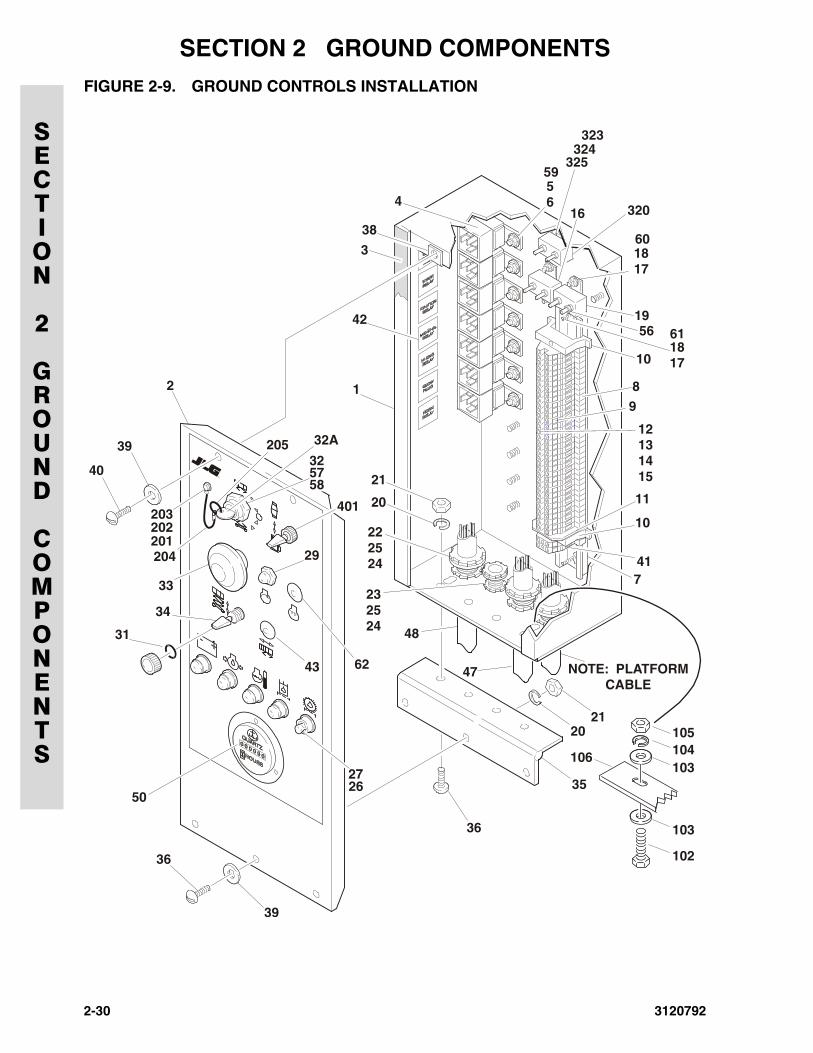
FIGURE 2-9. GROUND CONTROLS INSTALLATION
202203
201
40
204
33
29
43
2627
36
39
36
20
35
21
741
10
10
1956
59
61
60
16
325
320
324323
4
38
42
56
1817
1817
11
9
8
12131415
NOTE: PLATFORMCABLE
47
48
62
20
21
222524
232524
34
31
32A
3220539
2 1
5758
401
50
3
105104103
103
102
106
2-30 3120792
SECTION 2 GROUND COMPONENTS
SECTION
2
GROUND
COMPONENTS
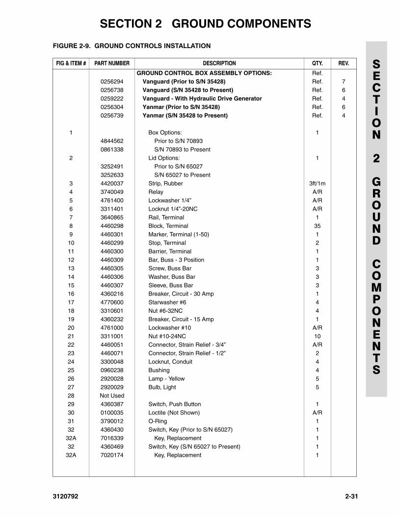
.FIGURE 2-9. GROUND CONTROLS INSTALLATION
FIG & ITEM # PART NUMBER DESCRIPTION QTY. REV.
GROUND CONTROL BOX ASSEMBLY OPTIONS: Ref.0256294 Vanguard (Prior to S/N 35428) Ref. 7
0256738 Vanguard (S/N 35428 to Present) Ref. 6
0259222 Vanguard - With Hydraulic Drive Generator Ref. 4
0256304 Yanmar (Prior to S/N 35428) Ref. 60256739 Yanmar (S/N 35428 to Present) Ref. 4
1 Box Options: 14844562 Prior to S/N 70893
0861338 S/N 70893 to Present
2 Lid Options: 13252491 Prior to S/N 65027
3252633 S/N 65027 to Present
3 4420037 Strip, Rubber 3ft/1m4 3740049 Relay A/R
5 4761400 Lockwasher 1/4” A/R
6 3311401 Locknut 1/4”-20NC A/R7 3640865 Rail, Terminal 1
8 4460298 Block, Terminal 35
9 4460301 Marker, Terminal (1-50) 110 4460299 Stop, Terminal 2
11 4460300 Barrier, Terminal 1
12 4460309 Bar, Buss - 3 Position 113 4460305 Screw, Buss Bar 3
14 4460306 Washer, Buss Bar 3
15 4460307 Sleeve, Buss Bar 316 4360216 Breaker, Circuit - 30 Amp 1
17 4770600 Starwasher #6 4
18 3310601 Nut #6-32NC 419 4360232 Breaker, Circuit - 15 Amp 1
20 4761000 Lockwasher #10 A/R
21 3311001 Nut #10-24NC 1022 4460051 Connector, Strain Relief - 3/4” A/R
23 4460071 Connector, Strain Relief - 1/2” 2
24 3300048 Locknut, Conduit 425 0960238 Bushing 4
26 2920028 Lamp - Yellow 5
27 2920029 Bulb, Light 528 Not Used
29 4360387 Switch, Push Button 1
30 0100035 Loctite (Not Shown) A/R
31 3790012 O-Ring 132 4360430 Switch, Key (Prior to S/N 65027) 1
32A 7016339 Key, Replacement 1
32 4360469 Switch, Key (S/N 65027 to Present) 132A 7020174 Key, Replacement 1
3120792 2-31
SECTION 2 GROUND COMPONENTS
SECTION
2
GROUND
COMPONENTS
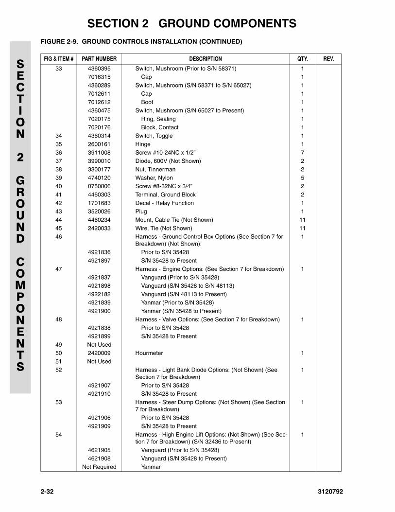
33 4360395 Switch, Mushroom (Prior to S/N 58371) 17016315 Cap 1
4360289 Switch, Mushroom (S/N 58371 to S/N 65027) 1
7012611 Cap 1
7012612 Boot 14360475 Switch, Mushroom (S/N 65027 to Present) 1
7020175 Ring, Sealing 1
7020176 Block, Contact 134 4360314 Switch, Toggle 1
35 2600161 Hinge 1
36 3911008 Screw #10-24NC x 1/2” 737 3990010 Diode, 600V (Not Shown) 2
38 3300177 Nut, Tinnerman 2
39 4740120 Washer, Nylon 540 0750806 Screw #8-32NC x 3/4” 2
41 4460303 Terminal, Ground Block 2
42 1701683 Decal - Relay Function 143 3520026 Plug 1
44 4460234 Mount, Cable Tie (Not Shown) 11
45 2420033 Wire, Tie (Not Shown) 1146 Harness - Ground Control Box Options (See Section 7 for
Breakdown) (Not Shown):1
4921836 Prior to S/N 35428
4921897 S/N 35428 to Present
47 Harness - Engine Options: (See Section 7 for Breakdown) 14921837 Vanguard (Prior to S/N 35428)
4921898 Vanguard (S/N 35428 to S/N 48113)
4922182 Vanguard (S/N 48113 to Present)4921839 Yanmar (Prior to S/N 35428)
4921900 Yanmar (S/N 35428 to Present)
48 Harness - Valve Options: (See Section 7 for Breakdown) 14921838 Prior to S/N 35428
4921899 S/N 35428 to Present
49 Not Used50 2420009 Hourmeter 1
51 Not Used
52 Harness - Light Bank Diode Options: (Not Shown) (See Section 7 for Breakdown)
1
4921907 Prior to S/N 354284921910 S/N 35428 to Present
53 Harness - Steer Dump Options: (Not Shown) (See Section 7 for Breakdown)
1
4921906 Prior to S/N 35428
4921909 S/N 35428 to Present
54 Harness - High Engine Lift Options: (Not Shown) (See Sec-tion 7 for Breakdown) (S/N 32436 to Present)
1
4621905 Vanguard (Prior to S/N 35428)4621908 Vanguard (S/N 35428 to Present)
Not Required Yanmar
FIGURE 2-9. GROUND CONTROLS INSTALLATION (CONTINUED)
FIG & ITEM # PART NUMBER DESCRIPTION QTY. REV.
2-32 3120792
SECTION 2 GROUND COMPONENTS
SECTION
2
GROUND
COMPONENTS
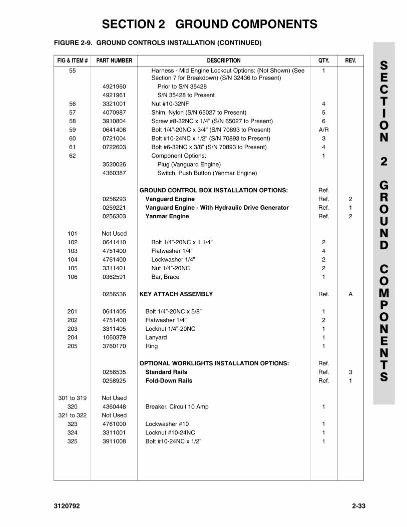
55 Harness - Mid Engine Lockout Options: (Not Shown) (See Section 7 for Breakdown) (S/N 32436 to Present)
1
4921960 Prior to S/N 354284921961 S/N 35428 to Present
56 3321001 Nut #10-32NF 4
57 4070987 Shim, Nylon (S/N 65027 to Present) 5
58 3910804 Screw #8-32NC x 1/4” (S/N 65027 to Present) 659 0641406 Bolt 1/4”-20NC x 3/4” (S/N 70893 to Present) A/R
60 0721004 Bolt #10-24NC x 1/2” (S/N 70893 to Present) 3
61 0722603 Bolt #6-32NC x 3/8” (S/N 70893 to Present) 462 Component Options: 1
3520026 Plug (Vanguard Engine)
4360387 Switch, Push Button (Yanmar Engine)
GROUND CONTROL BOX INSTALLATION OPTIONS: Ref.
0256293 Vanguard Engine Ref. 20259221 Vanguard Engine - With Hydraulic Drive Generator Ref. 1
0256303 Yanmar Engine Ref. 2
101 Not Used
102 0641410 Bolt 1/4”-20NC x 1 1/4” 2
103 4751400 Flatwasher 1/4” 4104 4761400 Lockwasher 1/4” 2
105 3311401 Nut 1/4”-20NC 2
106 0362591 Bar, Brace 1
0256536 KEY ATTACH ASSEMBLY Ref. A
201 0641405 Bolt 1/4”-20NC x 5/8” 1
202 4751400 Flatwasher 1/4” 2
203 3311405 Locknut 1/4”-20NC 1204 1060379 Lanyard 1
205 3760170 Ring 1
OPTIONAL WORKLIGHTS INSTALLATION OPTIONS: Ref.
0256535 Standard Rails Ref. 3
0258925 Fold-Down Rails Ref. 1
301 to 319 Not Used
320 4360448 Breaker, Circuit 10 Amp 1321 to 322 Not Used
323 4761000 Lockwasher #10 1
324 3311001 Locknut #10-24NC 1
325 3911008 Bolt #10-24NC x 1/2” 1
FIGURE 2-9. GROUND CONTROLS INSTALLATION (CONTINUED)
FIG & ITEM # PART NUMBER DESCRIPTION QTY. REV.
3120792 2-33
SECTION 2 GROUND COMPONENTS
SECTION
2
GROUND
COMPONENTS
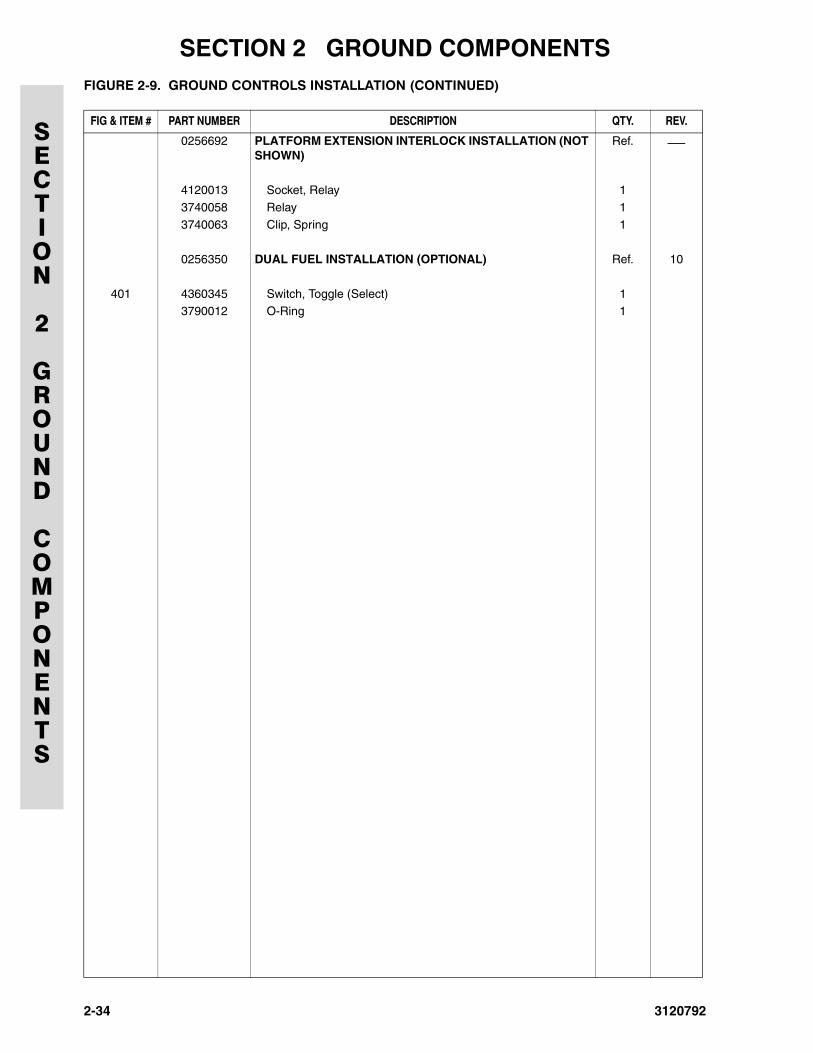
0256692 PLATFORM EXTENSION INTERLOCK INSTALLATION (NOT SHOWN)
Ref. ⎯
4120013 Socket, Relay 1
3740058 Relay 1
3740063 Clip, Spring 1
0256350 DUAL FUEL INSTALLATION (OPTIONAL) Ref. 10
401 4360345 Switch, Toggle (Select) 13790012 O-Ring 1
FIGURE 2-9. GROUND CONTROLS INSTALLATION (CONTINUED)
FIG & ITEM # PART NUMBER DESCRIPTION QTY. REV.
2-34 3120792
SECTION 2 GROUND COMPONENTS
SECTION
2
GROUND
COMPONENTS
FIGURE 2-9. GROUND CONTROLS INSTALLATION (CONTINUED)
FIG & ITEM # PART NUMBER DESCRIPTION QTY. REV.
3120792 2-35
SECTION 2 GROUND COMPONENTS
SECTION
2
GROUND
COMPONENTS
FIGURE 2-10. HOOD INSTALLATIONS
6
6
6
6
6
2
3125
20
6
7
8
8
7
7
7
7
7
7
9
6
4
5
1 11
7
7
10
18
7
7
7
7
777
88
8
8
8
8
6
6
6
6
6
2
13125
7
8
8
7
7
7
7
7
4
1516
1516
1516
5
17
18
7
7
77
7 8
8
86
67
7
117
14
78
78
19
NOTE: REPLACEMENT DECALS MUST BE ORDERED SEPARATELY - SEE SECTION 8.
2-36 3120792
SECTION 2 GROUND COMPONENTS
SECTION
2
GROUND
COMPONENTS
.FIGURE 2-10. HOOD INSTALLATIONS
FIG & ITEM # PART NUMBER DESCRIPTION QTY. REV.
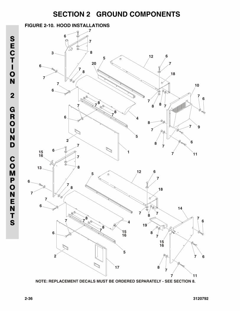
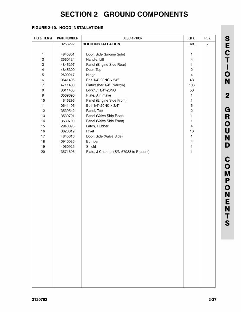
0256292 HOOD INSTALLATION Ref. 7
1 4845301 Door, Side (Engine Side) 1
2 2560124 Handle, Lift 4
3 4845297 Panel (Engine Side Rear) 14 4845300 Door, Top 2
5 2600217 Hinge 4
6 0641405 Bolt 1/4”-20NC x 5/8” 487 4711400 Flatwasher 1/4” (Narrow) 106
8 3311405 Locknut 1/4”-20NC 53
9 3539690 Plate, Air Intake 110 4845296 Panel (Engine Side Front) 1
11 0641406 Bolt 1/4”-20NC x 3/4” 5
12 3539542 Panel, Top 213 3539701 Panel (Valve Side Rear) 1
14 3539700 Panel (Valve Side Front) 1
15 2940095 Latch, Rubber 416 3820019 Rivet 16
17 4845316 Door, Side (Valve Side) 1
18 0940036 Bumper 419 4060925 Shield 1
20 3571696 Plate, J-Channel (S/N 67933 to Present) 1
3120792 2-37
SECTION 2 GROUND COMPONENTS
SECTION
2
GROUND
COMPONENTS
FIGURE 2-10. HOOD INSTALLATIONS (CONTINUED)
FIG & ITEM # PART NUMBER DESCRIPTION QTY. REV.
2-38 3120792
3120792
SECTION 3 SCISSOR ARMS
SECTION
3
SCISSOR
ARMS
TABLE OF CONTENTS
FIGURE DESCRIPTION PAGE
3-1 Scissor Arms Installation. . . . . . . . . . . . . . . . . . . . . . . . . . . . . . . . . . . . . . . . . . . . . . . . . . . . . . . 3-2
3-1
SECTION 3 SCISSOR ARMS
SECTION
3
SCISSOR
ARMS
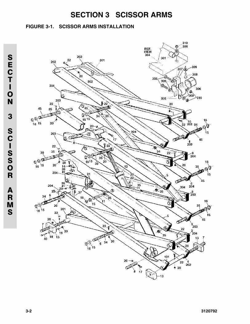
FIGURE 3-1. SCISSOR ARMS INSTALLATION
3-2 3120792
SECTION 3 SCISSOR ARMS
SECTION
3
SCISSOR
ARMS
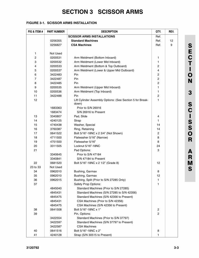
.FIGURE 3-1. SCISSOR ARMS INSTALLATION
FIG & ITEM # PART NUMBER DESCRIPTION QTY. REV.
SCISSOR ARMS INSTALLATIONS Ref.0256355 Standard Machines Ref. 12
0256827 CSA Machines Ref. 9
1 Not Used2 0200531 Arm Weldment (Bottom Inboard) 1
3 0200532 Arm Weldment (Lower Mid Inboard) 1
4 0200533 Arm Weldment (Bottom & Top Outboard) 25 0200537 Arm Weldment (Lower & Upper Mid Outboard) 4
6 3422483 Pin 2
7 3422487 Pin 28 3422485 Pin 2
9 0200535 Arm Weldment (Upper Mid Inboard) 1
10 0200536 Arm Weldment (Top Inboard) 111 3422488 Pin 2
12 Lift Cylinder Assembly Options: (See Section 5 for Break-down)
1
1683363 Prior to S/N 26916
1683474 S/N 26916 to Present13 3340807 Pad, Slide 4
14 4240125 Strap 1
15 4740438 Washer, Special 1416 3760387 Ring, Retaining 14
17 0641522 Bolt 5/16”-18NC x 2 3/4” (Not Shown) 2
18 4711500 Flatwasher 5/16” (Narrow) 819 4751500 Flatwasher 5/16” 8
20 3311505 Locknut 5/16”-18NC 24
21 Pad Options: 33340645 Prior to S/N 47184
3340841 S/N 47184 to Present
22 0681520 Bolt 5/16”-18NC x 2 1/2” (Grade 8) 1223 to 33 Not Used
34 0962010 Bushing, Garmax 8
35 0962010 Bushing, Garmax 1236 0962015 Bushing, Split (Prior to S/N 27285 Only) 1
37 Safety Prop Options: 1
4845040 Standard Machines (Prior to S/N 27285)4845431 Standard Machines (S/N 27285 to S/N 42356)
4845475 Standard Machines (S/N 42356 to Present)
4845431 CSA Machines (Prior to S/N 42356)4845475 CSA Machines (S/N 42356 to Present)
38 0641508 Bolt 5/16”-18NC x 1” 2
39 Pin, Options: 2
3422554 Standard Machines (Prior to S/N 37797)3422597 Standard Machines (S/N 37797 to Present)
3422587 CSA Machines
40 0641516 Bolt 5/16”-18NC x 2” 841 4240128 Strap (S/N 30515 to Present) 1
3120792 3-3
SECTION 3 SCISSOR ARMS
SECTION
3
SCISSOR
ARMS
42 to 44 Not Used45 Pin, Options: 5
3422483 Standard Machines
3422587 CSA Machines
— — — — — — —Arm Kit Options: (Includes Items 2-5, 9, 10 & 37) 1
2901352 Prior to S/N 42356
2901504 S/N 42356 to Present
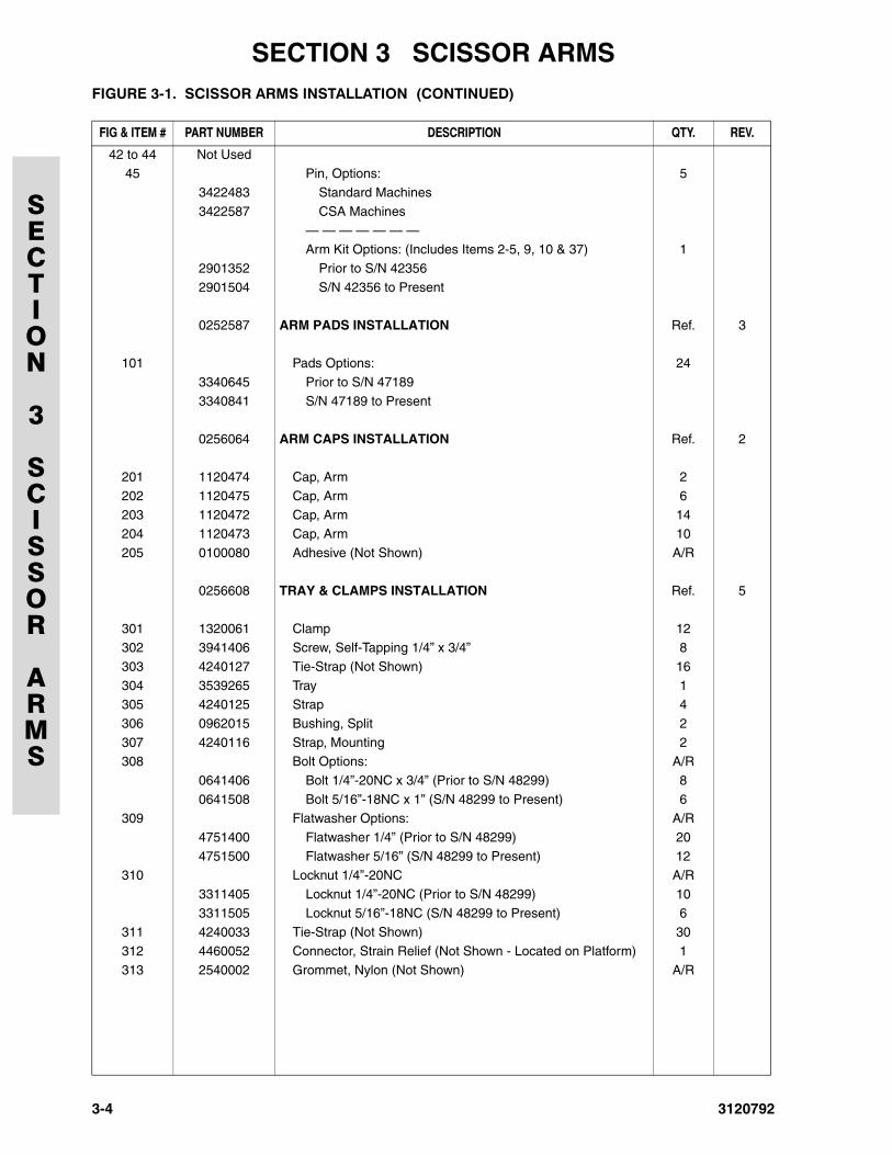
0252587 ARM PADS INSTALLATION Ref. 3
101 Pads Options: 24
3340645 Prior to S/N 47189
3340841 S/N 47189 to Present
0256064 ARM CAPS INSTALLATION Ref. 2
201 1120474 Cap, Arm 2
202 1120475 Cap, Arm 6
203 1120472 Cap, Arm 14204 1120473 Cap, Arm 10
205 0100080 Adhesive (Not Shown) A/R
0256608 TRAY & CLAMPS INSTALLATION Ref. 5
301 1320061 Clamp 12302 3941406 Screw, Self-Tapping 1/4” x 3/4” 8
303 4240127 Tie-Strap (Not Shown) 16
304 3539265 Tray 1305 4240125 Strap 4
306 0962015 Bushing, Split 2
307 4240116 Strap, Mounting 2308 Bolt Options: A/R
0641406 Bolt 1/4”-20NC x 3/4” (Prior to S/N 48299) 8
0641508 Bolt 5/16”-18NC x 1” (S/N 48299 to Present) 6309 Flatwasher Options: A/R
4751400 Flatwasher 1/4” (Prior to S/N 48299) 20
4751500 Flatwasher 5/16” (S/N 48299 to Present) 12310 Locknut 1/4”-20NC A/R
3311405 Locknut 1/4”-20NC (Prior to S/N 48299) 10
3311505 Locknut 5/16”-18NC (S/N 48299 to Present) 6311 4240033 Tie-Strap (Not Shown) 30
312 4460052 Connector, Strain Relief (Not Shown - Located on Platform) 1
313 2540002 Grommet, Nylon (Not Shown) A/R
FIGURE 3-1. SCISSOR ARMS INSTALLATION (CONTINUED)
FIG & ITEM # PART NUMBER DESCRIPTION QTY. REV.
3-4 3120792
3120792
SECTION 4 PLATFORM
SECTION
4
PLATFORM
TABLE OF CONTENTS
FIGURE DESCRIPTION PAGE
4-1 Platform Components Installation - Manual Operated Extension . . . . . . . . . . . . . . . . . . . . . . . . 4-24-2 Standard Handrails & Extension Installation (Manually Operated Platform). . . . . . . . . . . . . . . . 4-6
4-3 Wide Platform Handrails & Extension Installation (Manually Operated Platform). . . . . . . . . . . . 4-10
4-4 Folddown Handrails & Extension Installation (Manually Operated Platform) . . . . . . . . . . . . . . . 4-14
4-5 Platform Console Box Assembly. . . . . . . . . . . . . . . . . . . . . . . . . . . . . . . . . . . . . . . . . . . . . . . . . 4-184-6 Controller Assembly (Prior to S/N 58990) . . . . . . . . . . . . . . . . . . . . . . . . . . . . . . . . . . . . . . . . . . 4-22
4-7 Controller Assembly (S/N 58990 to Present) . . . . . . . . . . . . . . . . . . . . . . . . . . . . . . . . . . . . . . . 4-24
4-1
SECTION 4 PLATFORM
SECTION
4
PLATFORM
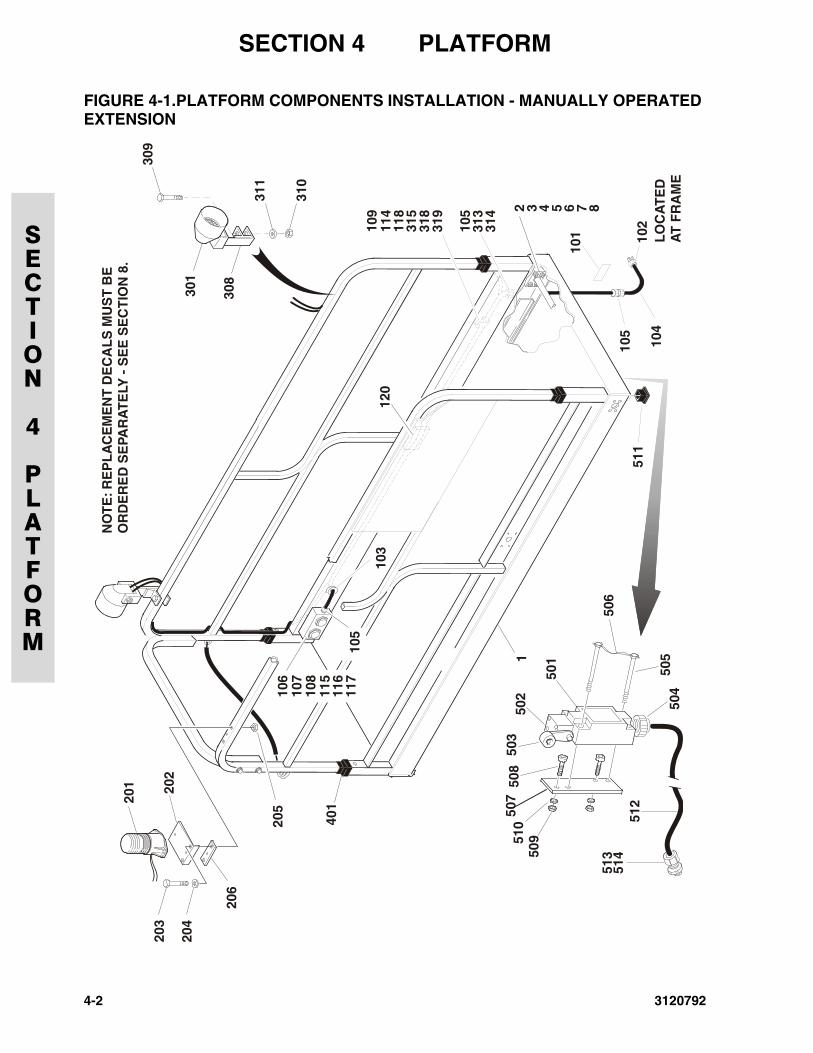
FIGURE 4-1.PLATFORM COMPONENTS INSTALLATION - MANUALLY OPERATEDEXTENSION
2 3 4 5 6 7 8
1 09
315
318
319
118
LO
CA
TE
DA
T F
RA
ME
301
3 08
309
311
3 10
201 20
220
3
204
4 01
206
205
1 14
101 10
210
5
1 05
313
314
104
511
1
106
107
1 08
115
116
117
105
103
120
501
506
505
504
503
508
507
50951
0 512
513
514
502
NO
TE
: RE
PL
AC
EM
EN
T D
EC
AL
S M
US
T B
EO
RD
ER
ED
SE
PAR
AT
ELY
- S
EE
SE
CT
ION
8.
4-2 3120792
SECTION 4 PLATFORM
SECTION
4
PLATFORM
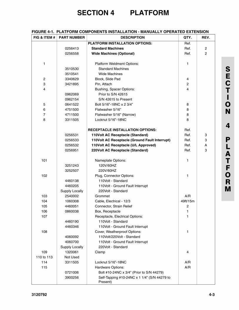
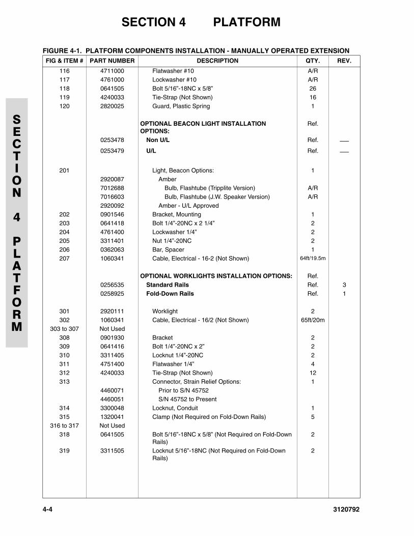
FIGURE 4-1. PLATFORM COMPONENTS INSTALLATION - MANUALLY OPERATED EXTENSIONFIG & ITEM # PART NUMBER DESCRIPTION QTY. REV.
PLATFORM INSTALLATION OPTIONS: Ref.0256413 Standard Machines Ref. 2
0256558 Wide Machines (Optional) Ref. 2
1 Platform Weldment Options: 13510530 Standard Machines
3510541 Wide Machines
2 3340629 Block, Slide Pad 43 3421895 Pin, Attach 2
4 Bushing, Spacer Options: 4
0962069 Prior to S/N 426150962154 S/N 42615 to Present
5 0641522 Bolt 5/16”-18NC x 2 3/4” 8
6 4751500 Flatwasher 5/16” 87 4711500 Flatwasher 5/16” (Narrow) 8
8 3311505 Locknut 5/16”-18NC 8
RECEPTACLE INSTALLATION OPTIONS: Ref.
0256531 110Volt AC Receptacle (Standard) Ref. 3
0256533 110Volt AC Receptacle (Ground Fault Interrupt) Ref. 30256532 110Volt AC Receptacle (U/L Approved) Ref. A
0256951 220Volt AC Receptacle (Standard) Ref. 3
101 Nameplate Options: 1
3251243 120V/60HZ
3252507 220V/60HZ102 Plug, Connector Options: 1
4460138 110Volt - Standard
4460205 110Volt - Ground Fault Interrupt Supply Locally 220Volt - Standard
103 2540002 Grommet A/R
104 1060308 Cable, Electrical - 12/3 49ft/15m105 4460051 Connector, Strain Relief 2
106 0860038 Box, Receptacle 1
107 Receptacle, Electrical Options: 14460190 110Volt - Standard
4460346 110Volt - Ground Fault Interrupt
108 Cover, Weatherproof Options: 14060092 110Volt/220Volt - Standard
4060700 110Volt - Ground Fault Interrupt
Supply Locally 220Volt - Standard
109 1320061 Clamp 4110 to 113 Not Used
114 3311505 Locknut 5/16”-18NC A/R
115 Hardware Options: A/R0721006 Bolt #10-24NC x 3/4” (Prior to S/N 44279)
3900256 Self-Tapping #10-24NC x 1 1/4” (S/N 44279 to Present)
3120792 4-3
SECTION 4 PLATFORM
SECTION
4
PLATFORM
116 4711000 Flatwasher #10 A/R117 4761000 Lockwasher #10 A/R
118 0641505 Bolt 5/16”-18NC x 5/8” 26
119 4240033 Tie-Strap (Not Shown) 16
120 2820025 Guard, Plastic Spring 1
OPTIONAL BEACON LIGHT INSTALLATION OPTIONS:
Ref.
0253478 Non U/L Ref. ⎯0253479 U/L Ref. ⎯
201 Light, Beacon Options: 1
2920087 Amber7012688 Bulb, Flashtube (Tripplite Version) A/R
7016603 Bulb, Flashtube (J.W. Speaker Version) A/R
2920092 Amber - U/L Approved202 0901546 Bracket, Mounting 1
203 0641418 Bolt 1/4”-20NC x 2 1/4” 2
204 4761400 Lockwasher 1/4” 2205 3311401 Nut 1/4”-20NC 2
206 0362063 Bar, Spacer 1
207 1060341 Cable, Electrical - 16-2 (Not Shown) 64ft/19.5m
OPTIONAL WORKLIGHTS INSTALLATION OPTIONS: Ref.
0256535 Standard Rails Ref. 30258925 Fold-Down Rails Ref. 1
301 2920111 Worklight 2302 1060341 Cable, Electrical - 16/2 (Not Shown) 65ft/20m
303 to 307 Not Used
308 0901930 Bracket 2309 0641416 Bolt 1/4”-20NC x 2” 2
310 3311405 Locknut 1/4”-20NC 2
311 4751400 Flatwasher 1/4” 4312 4240033 Tie-Strap (Not Shown) 12
313 Connector, Strain Relief Options: 1
4460071 Prior to S/N 457524460051 S/N 45752 to Present
314 3300048 Locknut, Conduit 1
315 1320041 Clamp (Not Required on Fold-Down Rails) 5316 to 317 Not Used
318 0641505 Bolt 5/16”-18NC x 5/8” (Not Required on Fold-Down Rails)
2
319 3311505 Locknut 5/16”-18NC (Not Required on Fold-Down Rails)
2
FIGURE 4-1. PLATFORM COMPONENTS INSTALLATION - MANUALLY OPERATED EXTENSION FIG & ITEM # PART NUMBER DESCRIPTION QTY. REV.
4-4 3120792
SECTION 4 PLATFORM
SECTION
4
PLATFORM
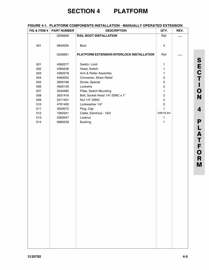
0256609 RAIL BOOT INSTALLATION Ref. ⎯
401 0840035 Boot 4
0256691 PLATFORM EXTENSION INTERLOCK INSTALLATION Ref. ⎯
501 4360277 Switch, Limit 1
502 4360236 Head, Switch 1503 4360278 Arm & Roller Assembly 1
504 4460052 Connector, Strain Relief 2
505 3900168 Screw, Special 2506 4920140 Lockwire 2
507 3534995 Plate, Switch Mounting 1
508 3931416 Bolt, Socket Head 1/4”-20NC x 1” 2509 3311401 Nut 1/4”-20NC 2
510 4761400 Lockwasher 1/4” 2
511 3520072 Plug, Cap 1512 1060341 Cable, Electrical - 16/2 54ft/16.5m
513 3300047 Locknut 1
514 0960239 Bushing 1
FIGURE 4-1. PLATFORM COMPONENTS INSTALLATION - MANUALLY OPERATED EXTENSION FIG & ITEM # PART NUMBER DESCRIPTION QTY. REV.
3120792 4-5
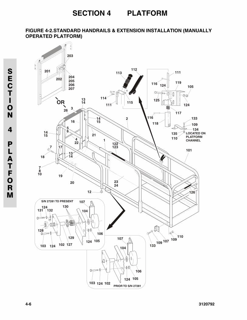
SECTION 4 PLATFORM
SECTION
4
PLATFORM
FIGURE 4-2.STANDARD HANDRAILS & EXTENSION INSTALLATION (MANUALLYOPERATED PLATFORM)
103 124124
102
104
107
105
106
124
1122123
101
2
13
113
114
201
202 204
203
205206207
115111
116
116117
118
111
119
124125
105
112
13
4
14
14
14
1418
19
20
12
107133
109109
110
7
78
10
15
15
5
16
6
17
126
103 124
124131 132
127
128
129
130
124102
104
107
105
106
S/N 27281 TO PRESENT
PRIOR TO S/N 27281
326
22
2324
133
LOCATED ONPLATFORMCHANNEL
134109
135110
OR
21
4-6 3120792
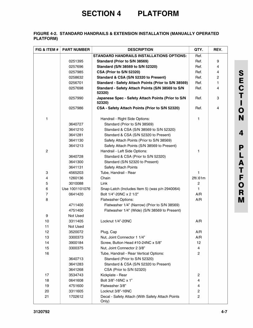
SECTION 4 PLATFORM
SECTION
4
PLATFORM
FIGURE 4-2. STANDARD HANDRAILS & EXTENSION INSTALLATION (MANUALLY OPERATED PLATFORM)
FIG & ITEM # PART NUMBER DESCRIPTION QTY. REV.
STANDARD HANDRAILS INSTALLATIONS OPTIONS: Ref.0251395 Standard (Prior to S/N 38569) Ref. 9
0257696 Standard (S/N 38569 to S/N 52320) Ref. 4
0257985 CSA (Prior to S/N 52320) Ref. 4
0258632 Standard & CSA (S/N 52320 to Present) Ref. 20256701 Standard - Safety Attach Points (Prior to S/N 38569) Ref. 1
0257698 Standard - Safety Attach Points (S/N 38569 to S/N 52320)
Ref. 4
0257990 Japanese Spec - Safety Attach Points (Prior to S/N 52320)
Ref. 3
0257986 CSA - Safety Attach Points (Prior to S/N 52320) Ref. 4
1 Handrail - Right Side Options: 1
3640727 Standard (Prior to S/N 38569)
3641210 Standard & CSA (S/N 38569 to S/N 52320)3641281 Standard & CSA (S/N 52320 to Present)
3641130 Safety Attach Points (Prior to S/N 38569)
3641213 Safety Attach Points (S/N 38569 to Present)2 Handrail - Left Side Options: 1
3640728 Standard & CSA (Prior to S/N 52320)
3641300 Standard (S/N 52320 to Present)3641131 Safety Attach Points
3 4565203 Tube, Handrail - Rear 1
4 1260136 Chain 2ft/.61m5 3010088 Link 2
6 Use 1001101076 Snap-Latch (Includes Item 5) (was p/n 2940064) 1
7 0641420 Bolt 1/4”-20NC x 2 1/2” A/R8 Flatwasher Options: A/R
4711400 Flatwasher 1/4” (Narrow) (Prior to S/N 38569)
4751400 Flatwasher 1/4” (Wide) (S/N 38569 to Present)9 Not Used
10 3311405 Locknut 1/4”-20NC A/R
11 Not Used12 3520072 Plug, Cap A/R
13 3300373 Nut, Joint Connector 1 1/4” A/R
14 3900184 Screw, Button Head #10-24NC x 5/8” 1215 3300375 Nut, Joint Connector 2 3/8” 4
16 Tube, Handrail - Rear Vertical Options: 2
3640713 Standard (Prior to S/N 52320)3641283 Standard & CSA (S/N 52320 to Present)
3641268 CSA (Prior to S/N 52320)
17 3534743 Kickplate - Rear 2
18 0641608 Bolt 3/8”-16NC x 1” 419 4751600 Flatwasher 3/8” 4
20 3311605 Locknut 3/8”-16NC 2
21 1702612 Decal - Safety Attach (With Safety Attach Points Only)
2
3120792 4-7
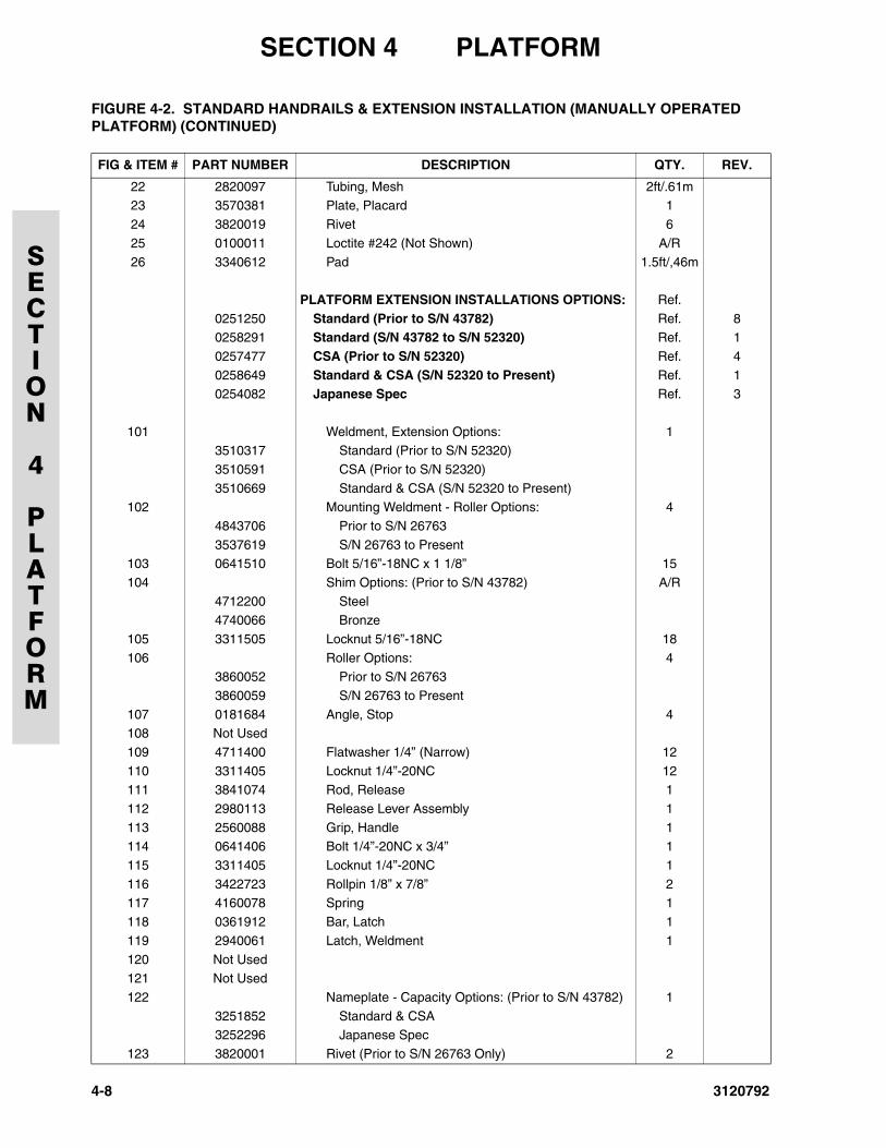
SECTION 4 PLATFORM
SECTION
4
PLATFORM
22 2820097 Tubing, Mesh 2ft/.61m23 3570381 Plate, Placard 1
24 3820019 Rivet 6
25 0100011 Loctite #242 (Not Shown) A/R
26 3340612 Pad 1.5ft/,46m
PLATFORM EXTENSION INSTALLATIONS OPTIONS: Ref.
0251250 Standard (Prior to S/N 43782) Ref. 80258291 Standard (S/N 43782 to S/N 52320) Ref. 1
0257477 CSA (Prior to S/N 52320) Ref. 4
0258649 Standard & CSA (S/N 52320 to Present) Ref. 10254082 Japanese Spec Ref. 3
101 Weldment, Extension Options: 13510317 Standard (Prior to S/N 52320)
3510591 CSA (Prior to S/N 52320)
3510669 Standard & CSA (S/N 52320 to Present)102 Mounting Weldment - Roller Options: 4
4843706 Prior to S/N 26763
3537619 S/N 26763 to Present103 0641510 Bolt 5/16”-18NC x 1 1/8” 15
104 Shim Options: (Prior to S/N 43782) A/R
4712200 Steel4740066 Bronze
105 3311505 Locknut 5/16”-18NC 18
106 Roller Options: 43860052 Prior to S/N 26763
3860059 S/N 26763 to Present
107 0181684 Angle, Stop 4108 Not Used
109 4711400 Flatwasher 1/4” (Narrow) 12
110 3311405 Locknut 1/4”-20NC 12111 3841074 Rod, Release 1
112 2980113 Release Lever Assembly 1
113 2560088 Grip, Handle 1114 0641406 Bolt 1/4”-20NC x 3/4” 1
115 3311405 Locknut 1/4”-20NC 1
116 3422723 Rollpin 1/8” x 7/8” 2117 4160078 Spring 1
118 0361912 Bar, Latch 1
119 2940061 Latch, Weldment 1
120 Not Used121 Not Used
122 Nameplate - Capacity Options: (Prior to S/N 43782) 1
3251852 Standard & CSA3252296 Japanese Spec
123 3820001 Rivet (Prior to S/N 26763 Only) 2
FIGURE 4-2. STANDARD HANDRAILS & EXTENSION INSTALLATION (MANUALLY OPERATED PLATFORM) (CONTINUED)
FIG & ITEM # PART NUMBER DESCRIPTION QTY. REV.
4-8 3120792
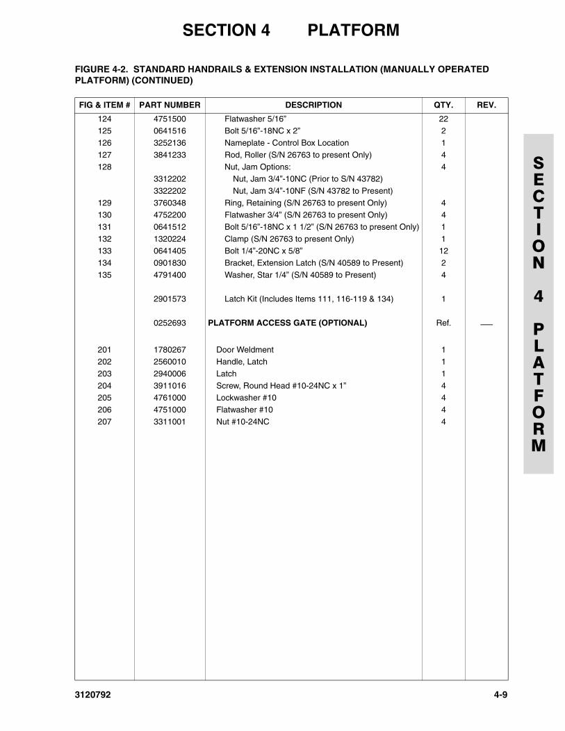
SECTION 4 PLATFORM
SECTION
4
PLATFORM
124 4751500 Flatwasher 5/16” 22125 0641516 Bolt 5/16”-18NC x 2” 2
126 3252136 Nameplate - Control Box Location 1
127 3841233 Rod, Roller (S/N 26763 to present Only) 4
128 Nut, Jam Options: 43312202 Nut, Jam 3/4”-10NC (Prior to S/N 43782)
3322202 Nut, Jam 3/4”-10NF (S/N 43782 to Present)
129 3760348 Ring, Retaining (S/N 26763 to present Only) 4130 4752200 Flatwasher 3/4” (S/N 26763 to present Only) 4
131 0641512 Bolt 5/16”-18NC x 1 1/2” (S/N 26763 to present Only) 1
132 1320224 Clamp (S/N 26763 to present Only) 1133 0641405 Bolt 1/4”-20NC x 5/8” 12
134 0901830 Bracket, Extension Latch (S/N 40589 to Present) 2
135 4791400 Washer, Star 1/4” (S/N 40589 to Present) 4
2901573 Latch Kit (Includes Items 111, 116-119 & 134) 1
0252693 PLATFORM ACCESS GATE (OPTIONAL) Ref. ⎯
201 1780267 Door Weldment 1202 2560010 Handle, Latch 1
203 2940006 Latch 1
204 3911016 Screw, Round Head #10-24NC x 1” 4205 4761000 Lockwasher #10 4
206 4751000 Flatwasher #10 4
207 3311001 Nut #10-24NC 4
FIGURE 4-2. STANDARD HANDRAILS & EXTENSION INSTALLATION (MANUALLY OPERATED PLATFORM) (CONTINUED)
FIG & ITEM # PART NUMBER DESCRIPTION QTY. REV.
3120792 4-9
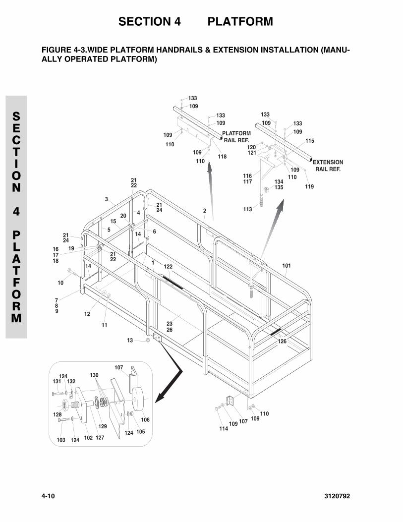
SECTION 4 PLATFORM
SECTION
4
PLATFORM
FIGURE 4-3.WIDE PLATFORM HANDRAILS & EXTENSION INSTALLATION (MANU-ALLY OPERATED PLATFORM)
4-10 3120792
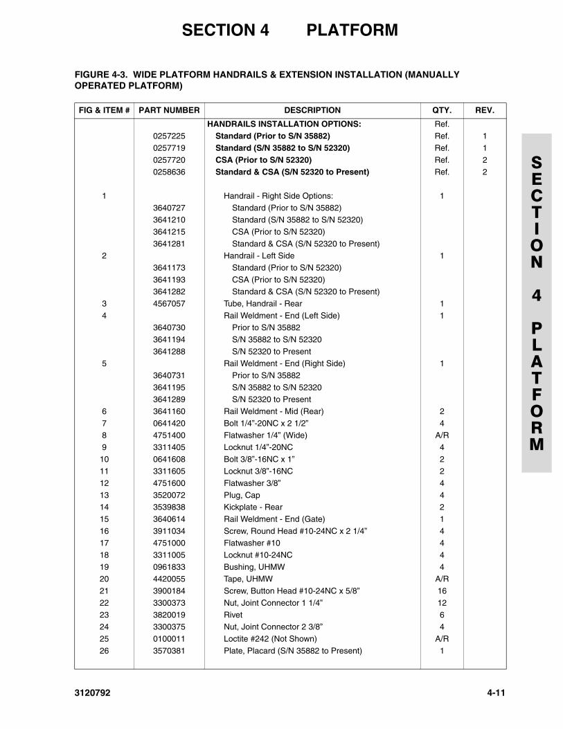
SECTION 4 PLATFORM
SECTION
4
PLATFORM
FIGURE 4-3. WIDE PLATFORM HANDRAILS & EXTENSION INSTALLATION (MANUALLY OPERATED PLATFORM)
FIG & ITEM # PART NUMBER DESCRIPTION QTY. REV.
HANDRAILS INSTALLATION OPTIONS: Ref.0257225 Standard (Prior to S/N 35882) Ref. 1
0257719 Standard (S/N 35882 to S/N 52320) Ref. 1
0257720 CSA (Prior to S/N 52320) Ref. 2
0258636 Standard & CSA (S/N 52320 to Present) Ref. 2
1 Handrail - Right Side Options: 1
3640727 Standard (Prior to S/N 35882)3641210 Standard (S/N 35882 to S/N 52320)
3641215 CSA (Prior to S/N 52320)
3641281 Standard & CSA (S/N 52320 to Present)2 Handrail - Left Side 1
3641173 Standard (Prior to S/N 52320)
3641193 CSA (Prior to S/N 52320)3641282 Standard & CSA (S/N 52320 to Present)
3 4567057 Tube, Handrail - Rear 1
4 Rail Weldment - End (Left Side) 13640730 Prior to S/N 35882
3641194 S/N 35882 to S/N 52320
3641288 S/N 52320 to Present5 Rail Weldment - End (Right Side) 1
3640731 Prior to S/N 35882
3641195 S/N 35882 to S/N 523203641289 S/N 52320 to Present
6 3641160 Rail Weldment - Mid (Rear) 2
7 0641420 Bolt 1/4”-20NC x 2 1/2” 48 4751400 Flatwasher 1/4” (Wide) A/R
9 3311405 Locknut 1/4”-20NC 4
10 0641608 Bolt 3/8”-16NC x 1” 211 3311605 Locknut 3/8”-16NC 2
12 4751600 Flatwasher 3/8” 4
13 3520072 Plug, Cap 414 3539838 Kickplate - Rear 2
15 3640614 Rail Weldment - End (Gate) 1
16 3911034 Screw, Round Head #10-24NC x 2 1/4” 417 4751000 Flatwasher #10 4
18 3311005 Locknut #10-24NC 4
19 0961833 Bushing, UHMW 420 4420055 Tape, UHMW A/R
21 3900184 Screw, Button Head #10-24NC x 5/8” 16
22 3300373 Nut, Joint Connector 1 1/4” 12
23 3820019 Rivet 624 3300375 Nut, Joint Connector 2 3/8” 4
25 0100011 Loctite #242 (Not Shown) A/R
26 3570381 Plate, Placard (S/N 35882 to Present) 1
3120792 4-11
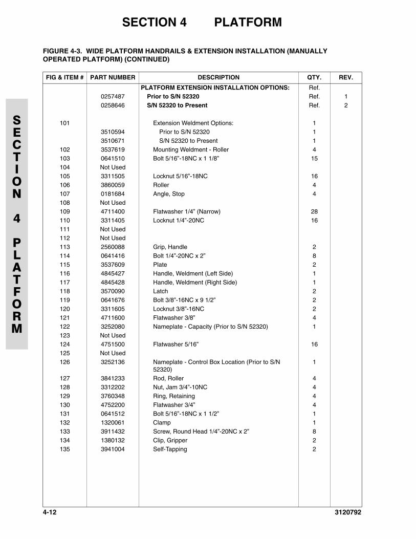
SECTION 4 PLATFORM
SECTION
4
PLATFORM
PLATFORM EXTENSION INSTALLATION OPTIONS: Ref.0257487 Prior to S/N 52320 Ref. 1
0258646 S/N 52320 to Present Ref. 2
101 Extension Weldment Options: 13510594 Prior to S/N 52320 1
3510671 S/N 52320 to Present 1
102 3537619 Mounting Weldment - Roller 4103 0641510 Bolt 5/16”-18NC x 1 1/8” 15
104 Not Used
105 3311505 Locknut 5/16”-18NC 16106 3860059 Roller 4
107 0181684 Angle, Stop 4
108 Not Used109 4711400 Flatwasher 1/4” (Narrow) 28
110 3311405 Locknut 1/4”-20NC 16
111 Not Used112 Not Used
113 2560088 Grip, Handle 2
114 0641416 Bolt 1/4”-20NC x 2” 8115 3537609 Plate 2
116 4845427 Handle, Weldment (Left Side) 1
117 4845428 Handle, Weldment (Right Side) 1118 3570090 Latch 2
119 0641676 Bolt 3/8”-16NC x 9 1/2” 2
120 3311605 Locknut 3/8”-16NC 2121 4711600 Flatwasher 3/8” 4
122 3252080 Nameplate - Capacity (Prior to S/N 52320) 1
123 Not Used124 4751500 Flatwasher 5/16” 16
125 Not Used
126 3252136 Nameplate - Control Box Location (Prior to S/N 52320)
1
127 3841233 Rod, Roller 4128 3312202 Nut, Jam 3/4”-10NC 4
129 3760348 Ring, Retaining 4
130 4752200 Flatwasher 3/4” 4131 0641512 Bolt 5/16”-18NC x 1 1/2” 1
132 1320061 Clamp 1
133 3911432 Screw, Round Head 1/4”-20NC x 2” 8
134 1380132 Clip, Gripper 2135 3941004 Self-Tapping 2
FIGURE 4-3. WIDE PLATFORM HANDRAILS & EXTENSION INSTALLATION (MANUALLY OPERATED PLATFORM) (CONTINUED)
FIG & ITEM # PART NUMBER DESCRIPTION QTY. REV.
4-12 3120792
SECTION 4 PLATFORM
SECTION
4
PLATFORM
FIGURE 4-3. WIDE PLATFORM HANDRAILS & EXTENSION INSTALLATION (MANUALLY OPERATED PLATFORM) (CONTINUED)
FIG & ITEM # PART NUMBER DESCRIPTION QTY. REV.
3120792 4-13
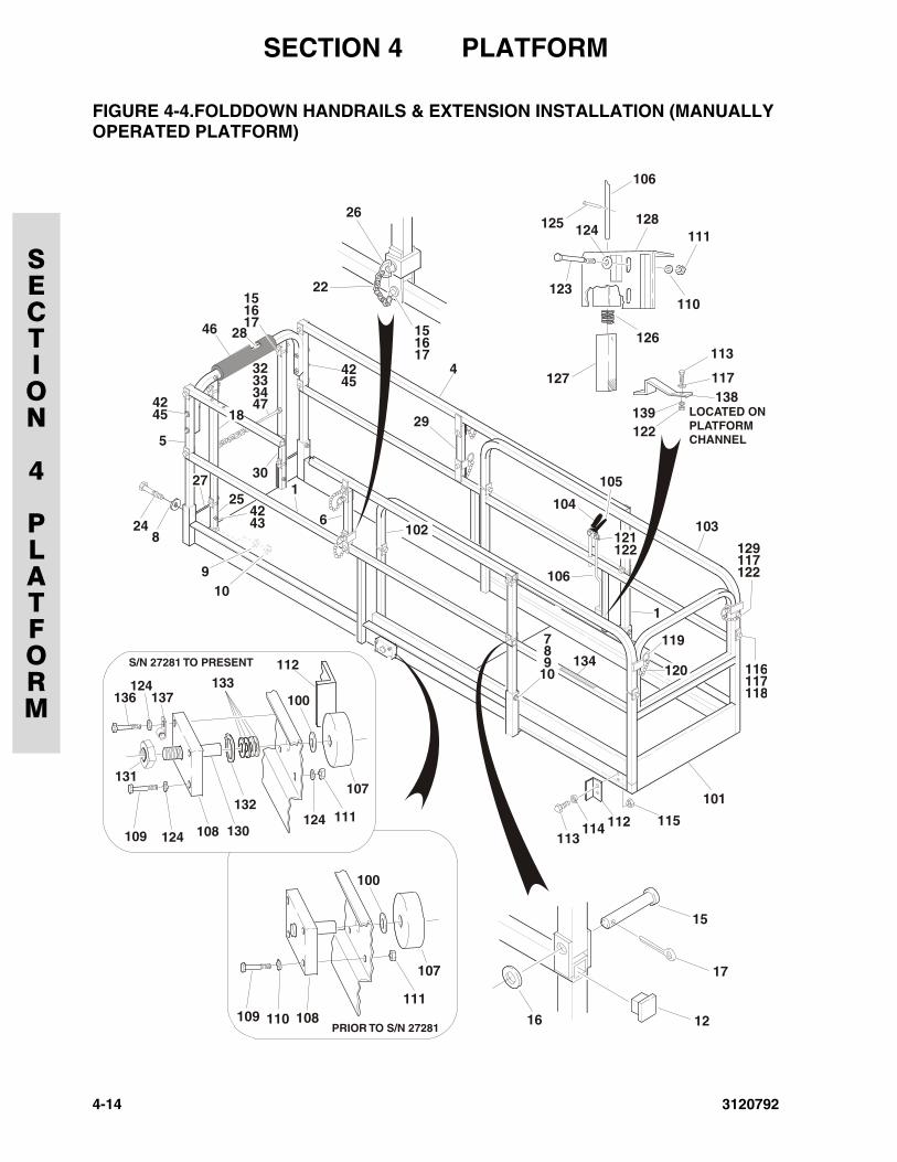
SECTION 4 PLATFORM
SECTION
4
PLATFORM
FIGURE 4-4.FOLDDOWN HANDRAILS & EXTENSION INSTALLATION (MANUALLYOPERATED PLATFORM)
109 110111
108
100
107
124
110
126
127
111128
123
125
106
PRIOR TO S/N 27281
1
6
4
1
103
119
104
105
106
29
46
15
15
42
30
4232
42
16
1617
17
4324
910
26
22
112113
114 115
101
116
129
117
117
118
122
8
45333447
45
5
18
2725
789
10134
102
120
121122
12
17
16
15
109 124
124136 137
130
131
132
133
124108
100
112
111
107
S/N 27281 TO PRESENT
113
LOCATED ONPLATFORMCHANNEL
138117
139122
28
4-14 3120792
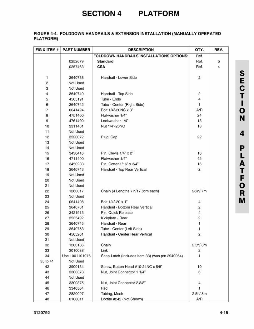
SECTION 4 PLATFORM
SECTION
4
PLATFORM
FIGURE 4-4. FOLDDOWN HANDRAILS & EXTENSION INSTALLATION (MANUALLY OPERATED PLATFORM)
FIG & ITEM # PART NUMBER DESCRIPTION QTY. REV.
FOLDDOWN HANDRAILS INSTALLATIONS OPTIONS: Ref.0252679 Standard Ref. 5
0257463 CSA Ref. 4
1 3640738 Handrail - Lower Side 22 Not Used
3 Not Used
4 3640740 Handrail - Top Side 25 4565191 Tube - Ends 4
6 3640742 Tube - Center (Right Side) 1
7 0641424 Bolt 1/4”-20NC x 3” A/R8 4751400 Flatwasher 1/4” 24
9 4761400 Lockwasher 1/4” 18
10 3311401 Nut 1/4”-20NC 1811 Not Used
12 3520072 Plug, Cap 22
13 Not Used14 Not Used
15 3430416 Pin, Clevis 1/4” x 2” 16
16 4711400 Flatwasher 1/4” 4217 3450203 Pin, Cotter 1/16” x 3/4” 16
18 3640743 Handrail - Top Rear Vertical 2
19 Not Used20 Not Used
21 Not Used
22 1260017 Chain (4 Lengths 7in/17.8cm each) 28in/.7m23 Not Used
24 0641408 Bolt 1/4”-20 x 1” 4
25 3640761 Handrail - Bottom Rear Vertical 226 3421913 Pin, Quick Release 4
27 3535492 Kickplate - Rear 2
28 3640745 Handrail - Rear 129 3640753 Tube - Center (Left Side) 1
30 4565261 Handrail - Center Rear Vertical 2
31 Not Used32 1260136 Chain 2.5ft/.8m
33 3010088 Link 2
34 Use 1001101076 Snap-Latch (Includes Item 33) (was p/n 2940064) 135 to 41 Not Used
42 3900184 Screw, Button Head #10-24NC x 5/8” 10
43 3300373 Nut, Joint Connector 1 1/4” 6
44 Not Used45 3300375 Nut, Joint Connector 2 3/8” 4
46 3340564 Pad 1
47 2820097 Tubing, Mesh 2.5ft/.8m48 0100011 Loctite #242 (Not Shown) A/R
3120792 4-15
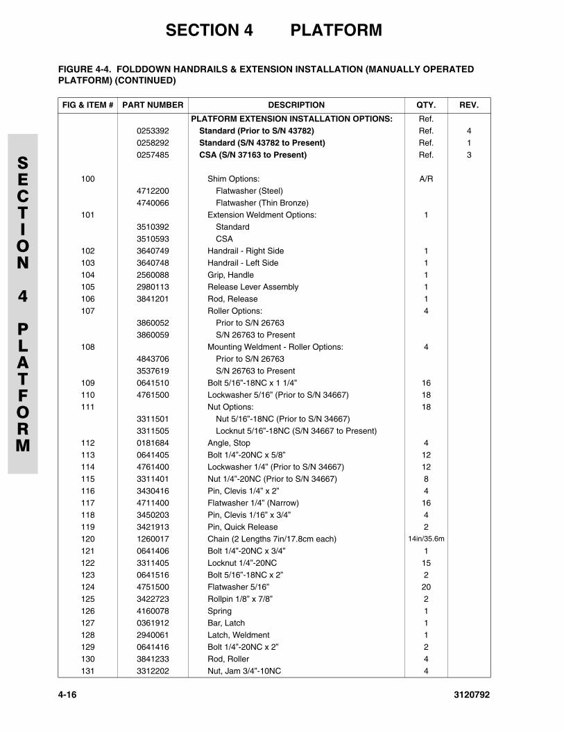
SECTION 4 PLATFORM
SECTION
4
PLATFORM
PLATFORM EXTENSION INSTALLATION OPTIONS: Ref.0253392 Standard (Prior to S/N 43782) Ref. 4
0258292 Standard (S/N 43782 to Present) Ref. 1
0257485 CSA (S/N 37163 to Present) Ref. 3
100 Shim Options: A/R
4712200 Flatwasher (Steel)
4740066 Flatwasher (Thin Bronze)101 Extension Weldment Options: 1
3510392 Standard
3510593 CSA102 3640749 Handrail - Right Side 1
103 3640748 Handrail - Left Side 1
104 2560088 Grip, Handle 1105 2980113 Release Lever Assembly 1
106 3841201 Rod, Release 1
107 Roller Options: 43860052 Prior to S/N 26763
3860059 S/N 26763 to Present
108 Mounting Weldment - Roller Options: 44843706 Prior to S/N 26763
3537619 S/N 26763 to Present
109 0641510 Bolt 5/16”-18NC x 1 1/4” 16110 4761500 Lockwasher 5/16” (Prior to S/N 34667) 18
111 Nut Options: 18
3311501 Nut 5/16”-18NC (Prior to S/N 34667)3311505 Locknut 5/16”-18NC (S/N 34667 to Present)
112 0181684 Angle, Stop 4
113 0641405 Bolt 1/4”-20NC x 5/8” 12114 4761400 Lockwasher 1/4” (Prior to S/N 34667) 12
115 3311401 Nut 1/4”-20NC (Prior to S/N 34667) 8
116 3430416 Pin, Clevis 1/4” x 2” 4117 4711400 Flatwasher 1/4” (Narrow) 16
118 3450203 Pin, Clevis 1/16” x 3/4” 4
119 3421913 Pin, Quick Release 2120 1260017 Chain (2 Lengths 7in/17.8cm each) 14in/35.6m
121 0641406 Bolt 1/4”-20NC x 3/4” 1
122 3311405 Locknut 1/4”-20NC 15123 0641516 Bolt 5/16”-18NC x 2” 2
124 4751500 Flatwasher 5/16” 20
125 3422723 Rollpin 1/8” x 7/8” 2
126 4160078 Spring 1127 0361912 Bar, Latch 1
128 2940061 Latch, Weldment 1
129 0641416 Bolt 1/4”-20NC x 2” 2130 3841233 Rod, Roller 4
131 3312202 Nut, Jam 3/4”-10NC 4
FIGURE 4-4. FOLDDOWN HANDRAILS & EXTENSION INSTALLATION (MANUALLY OPERATED PLATFORM) (CONTINUED)
FIG & ITEM # PART NUMBER DESCRIPTION QTY. REV.
4-16 3120792
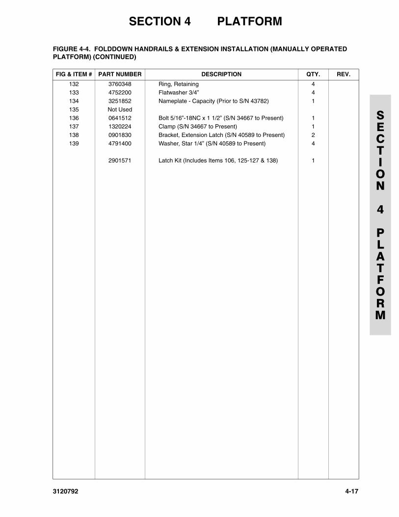
SECTION 4 PLATFORM
SECTION
4
PLATFORM
132 3760348 Ring, Retaining 4133 4752200 Flatwasher 3/4” 4
134 3251852 Nameplate - Capacity (Prior to S/N 43782) 1
135 Not Used
136 0641512 Bolt 5/16”-18NC x 1 1/2” (S/N 34667 to Present) 1137 1320224 Clamp (S/N 34667 to Present) 1
138 0901830 Bracket, Extension Latch (S/N 40589 to Present) 2
139 4791400 Washer, Star 1/4” (S/N 40589 to Present) 4
2901571 Latch Kit (Includes Items 106, 125-127 & 138) 1
FIGURE 4-4. FOLDDOWN HANDRAILS & EXTENSION INSTALLATION (MANUALLY OPERATED PLATFORM) (CONTINUED)
FIG & ITEM # PART NUMBER DESCRIPTION QTY. REV.
3120792 4-17
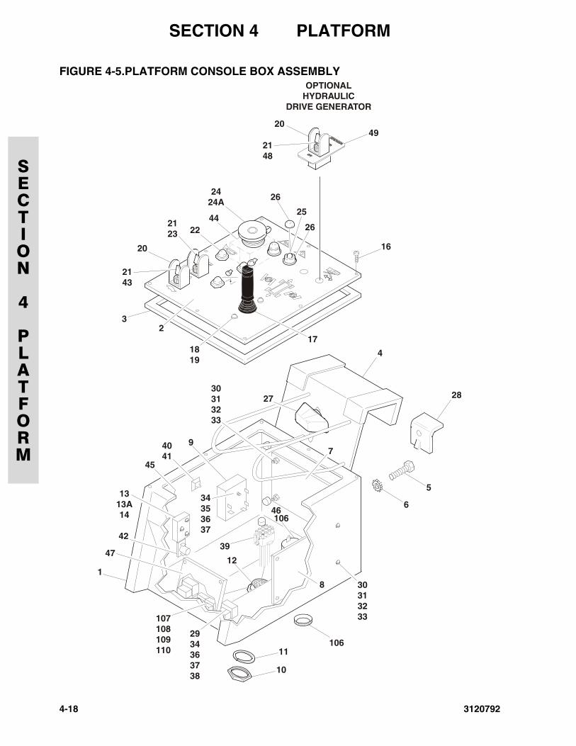
SECTION 4 PLATFORM
SECTION
4
PLATFORM
FIGURE 4-5.PLATFORM CONSOLE BOX ASSEMBLY
1
42
47
23
20
20
2244
26
26
25
2424A
2123
2143
4
28
5
106
6
8
10646
12
39
2934363738
107108109110
7
34353637
94041
45
30313233
30313233
27
11
10
1313A14
16
49
OPTIONALHYDRAULIC
DRIVE GENERATOR
171819
2148
4-18 3120792
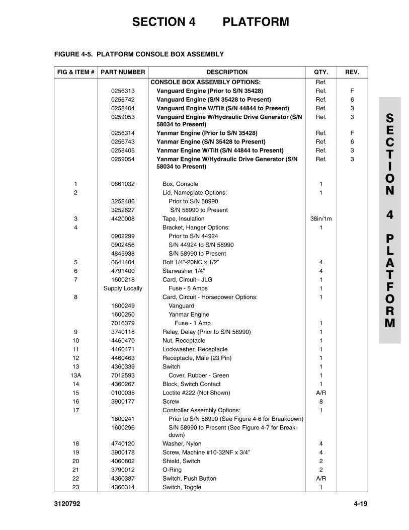
SECTION 4 PLATFORM
SECTION
4
PLATFORM
FIGURE 4-5. PLATFORM CONSOLE BOX ASSEMBLY
FIG & ITEM # PART NUMBER DESCRIPTION QTY. REV.
CONSOLE BOX ASSEMBLY OPTIONS: Ref.0256313 Vanguard Engine (Prior to S/N 35428) Ref. F
0256742 Vanguard Engine (S/N 35428 to Present) Ref. 6
0258404 Vanguard Engine W/Tilt (S/N 44844 to Present) Ref. 3
0259053 Vanguard Engine W/Hydraulic Drive Generator (S/N 58034 to Present)
Ref. 3
0256314 Yanmar Engine (Prior to S/N 35428) Ref. F0256743 Yanmar Engine (S/N 35428 to Present) Ref. 6
0258405 Yanmar Engine W/Tilt (S/N 44844 to Present) Ref. 3
0259054 Yanmar Engine W/Hydraulic Drive Generator (S/N 58034 to Present)
Ref. 3
1 0861032 Box, Console 1
2 Lid, Nameplate Options: 1
3252486 Prior to S/N 589903252627 S/N 58990 to Present
3 4420008 Tape, Insulation 38in/1m
4 Bracket, Hanger Options: 10902299 Prior to S/N 44924
0902456 S/N 44924 to S/N 58990
4845938 S/N 58990 to Present5 0641404 Bolt 1/4”-20NC x 1/2” 4
6 4791400 Starwasher 1/4” 4
7 1600218 Card, Circuit - JLG 1Supply Locally Fuse - 5 Amps 1
8 Card, Circuit - Horsepower Options: 1
1600249 Vanguard1600250 Yanmar Engine
7016379 Fuse - 1 Amp 1
9 3740118 Relay, Delay (Prior to S/N 58990) 110 4460470 Nut, Receptacle 1
11 4460471 Lockwasher, Receptacle 1
12 4460463 Receptacle, Male (23 Pin) 113 4360339 Switch 1
13A 7012593 Cover, Rubber - Green 1
14 4360267 Block, Switch Contact 115 0100035 Loctite #222 (Not Shown) A/R
16 3900177 Screw 8
17 Controller Assembly Options: 11600241 Prior to S/N 58990 (See Figure 4-6 for Breakdown)
1600296 S/N 58990 to Present (See Figure 4-7 for Break-down)
18 4740120 Washer, Nylon 4
19 3900178 Screw, Machine #10-32NF x 3/4” 4
20 4060802 Shield, Switch 221 3790012 O-Ring 2
22 4360387 Switch, Push Button A/R
23 4360314 Switch, Toggle 1
3120792 4-19
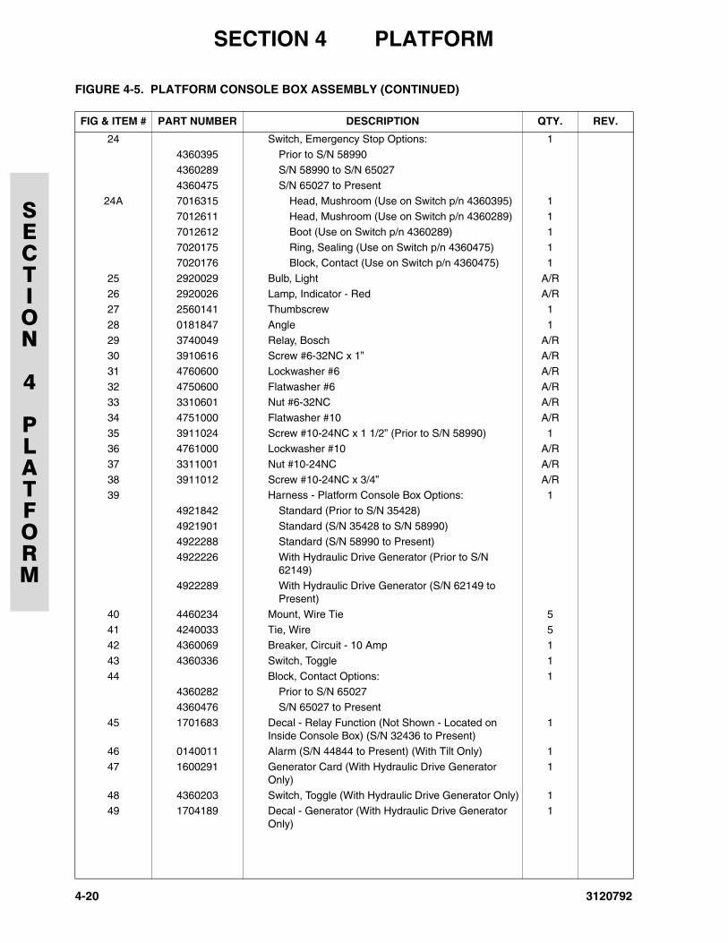
SECTION 4 PLATFORM
SECTION
4
PLATFORM
24 Switch, Emergency Stop Options: 14360395 Prior to S/N 58990
4360289 S/N 58990 to S/N 65027
4360475 S/N 65027 to Present
24A 7016315 Head, Mushroom (Use on Switch p/n 4360395) 17012611 Head, Mushroom (Use on Switch p/n 4360289) 1
7012612 Boot (Use on Switch p/n 4360289) 1
7020175 Ring, Sealing (Use on Switch p/n 4360475) 17020176 Block, Contact (Use on Switch p/n 4360475) 1
25 2920029 Bulb, Light A/R
26 2920026 Lamp, Indicator - Red A/R27 2560141 Thumbscrew 1
28 0181847 Angle 1
29 3740049 Relay, Bosch A/R30 3910616 Screw #6-32NC x 1” A/R
31 4760600 Lockwasher #6 A/R
32 4750600 Flatwasher #6 A/R33 3310601 Nut #6-32NC A/R
34 4751000 Flatwasher #10 A/R
35 3911024 Screw #10-24NC x 1 1/2” (Prior to S/N 58990) 136 4761000 Lockwasher #10 A/R
37 3311001 Nut #10-24NC A/R
38 3911012 Screw #10-24NC x 3/4” A/R39 Harness - Platform Console Box Options: 1
4921842 Standard (Prior to S/N 35428)
4921901 Standard (S/N 35428 to S/N 58990)4922288 Standard (S/N 58990 to Present)
4922226 With Hydraulic Drive Generator (Prior to S/N 62149)
4922289 With Hydraulic Drive Generator (S/N 62149 to Present)
40 4460234 Mount, Wire Tie 5
41 4240033 Tie, Wire 542 4360069 Breaker, Circuit - 10 Amp 1
43 4360336 Switch, Toggle 1
44 Block, Contact Options: 14360282 Prior to S/N 65027
4360476 S/N 65027 to Present
45 1701683 Decal - Relay Function (Not Shown - Located on Inside Console Box) (S/N 32436 to Present)
1
46 0140011 Alarm (S/N 44844 to Present) (With Tilt Only) 1
47 1600291 Generator Card (With Hydraulic Drive Generator Only)
1
48 4360203 Switch, Toggle (With Hydraulic Drive Generator Only) 149 1704189 Decal - Generator (With Hydraulic Drive Generator
Only)1
FIGURE 4-5. PLATFORM CONSOLE BOX ASSEMBLY (CONTINUED)
FIG & ITEM # PART NUMBER DESCRIPTION QTY. REV.
4-20 3120792
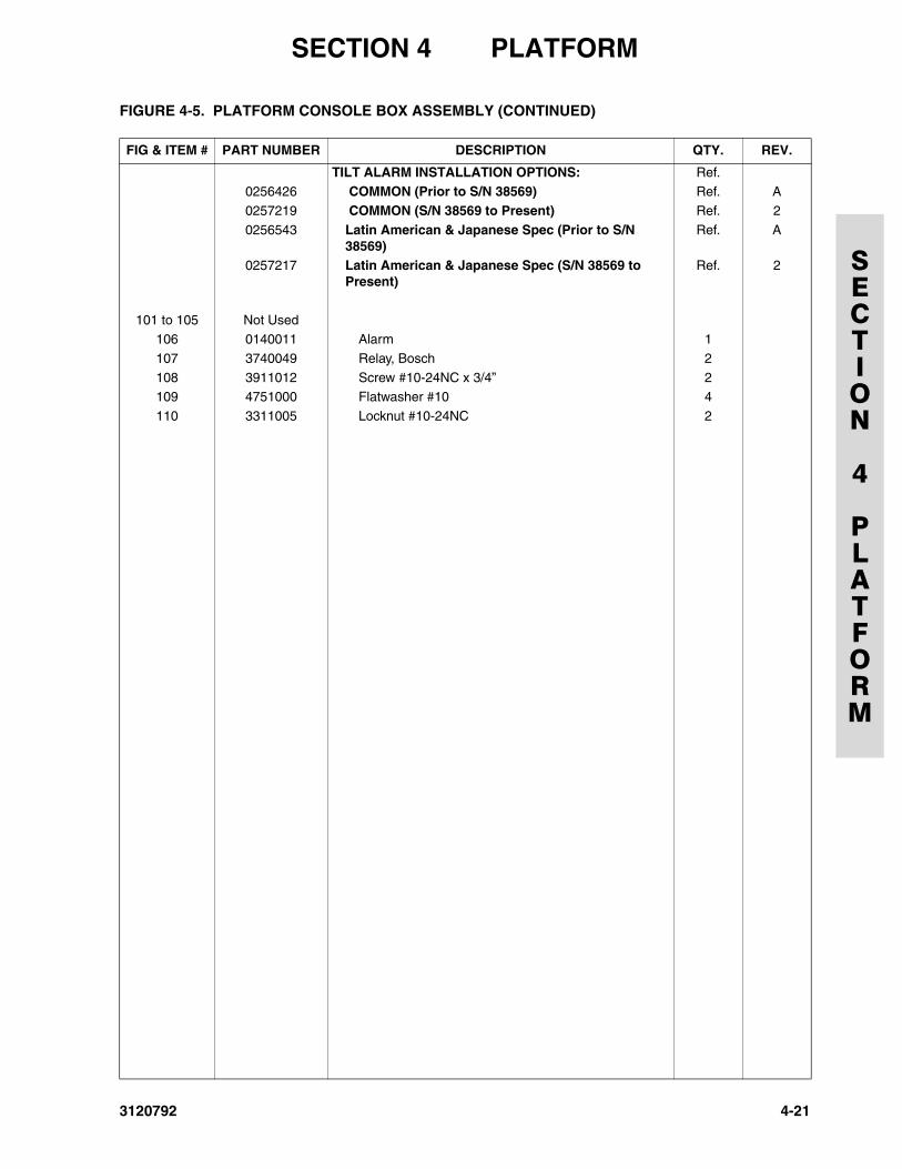
SECTION 4 PLATFORM
SECTION
4
PLATFORM
TILT ALARM INSTALLATION OPTIONS: Ref.0256426 COMMON (Prior to S/N 38569) Ref. A
0257219 COMMON (S/N 38569 to Present) Ref. 2
0256543 Latin American & Japanese Spec (Prior to S/N 38569)
Ref. A
0257217 Latin American & Japanese Spec (S/N 38569 to Present)
Ref. 2
101 to 105 Not Used106 0140011 Alarm 1
107 3740049 Relay, Bosch 2
108 3911012 Screw #10-24NC x 3/4” 2109 4751000 Flatwasher #10 4
110 3311005 Locknut #10-24NC 2
FIGURE 4-5. PLATFORM CONSOLE BOX ASSEMBLY (CONTINUED)
FIG & ITEM # PART NUMBER DESCRIPTION QTY. REV.
3120792 4-21
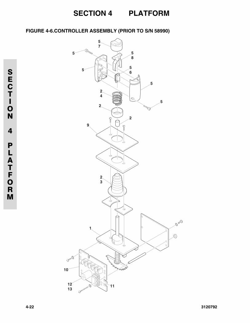
SECTION 4 PLATFORM
SECTION
4
PLATFORM
FIGURE 4-6.CONTROLLER ASSEMBLY (PRIOR TO S/N 58990)
57
5
5
58
56
24
2
9
2
5
5
23
1
10
1213
11
4-22 3120792
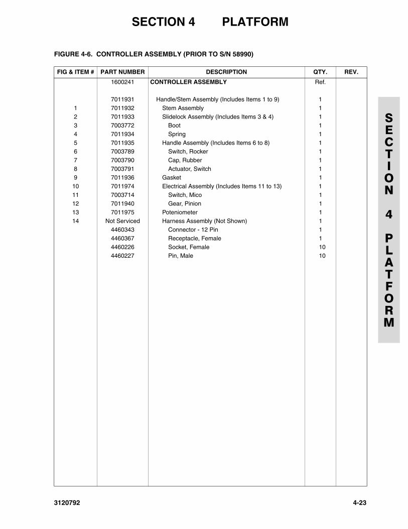
SECTION 4 PLATFORM
SECTION
4
PLATFORM
FIGURE 4-6. CONTROLLER ASSEMBLY (PRIOR TO S/N 58990)
FIG & ITEM # PART NUMBER DESCRIPTION QTY. REV.
1600241 CONTROLLER ASSEMBLY Ref.
7011931 Handle/Stem Assembly (Includes Items 1 to 9) 1
1 7011932 Stem Assembly 1
2 7011933 Slidelock Assembly (Includes Items 3 & 4) 13 7003772 Boot 1
4 7011934 Spring 1
5 7011935 Handle Assembly (Includes Items 6 to 8) 16 7003789 Switch, Rocker 1
7 7003790 Cap, Rubber 1
8 7003791 Actuator, Switch 19 7011936 Gasket 1
10 7011974 Electrical Assembly (Includes Items 11 to 13) 1
11 7003714 Switch, Mico 112 7011940 Gear, Pinion 1
13 7011975 Poteniometer 1
14 Not Serviced Harness Assembly (Not Shown) 14460343 Connector - 12 Pin 1
4460367 Receptacle, Female 1
4460226 Socket, Female 104460227 Pin, Male 10
3120792 4-23
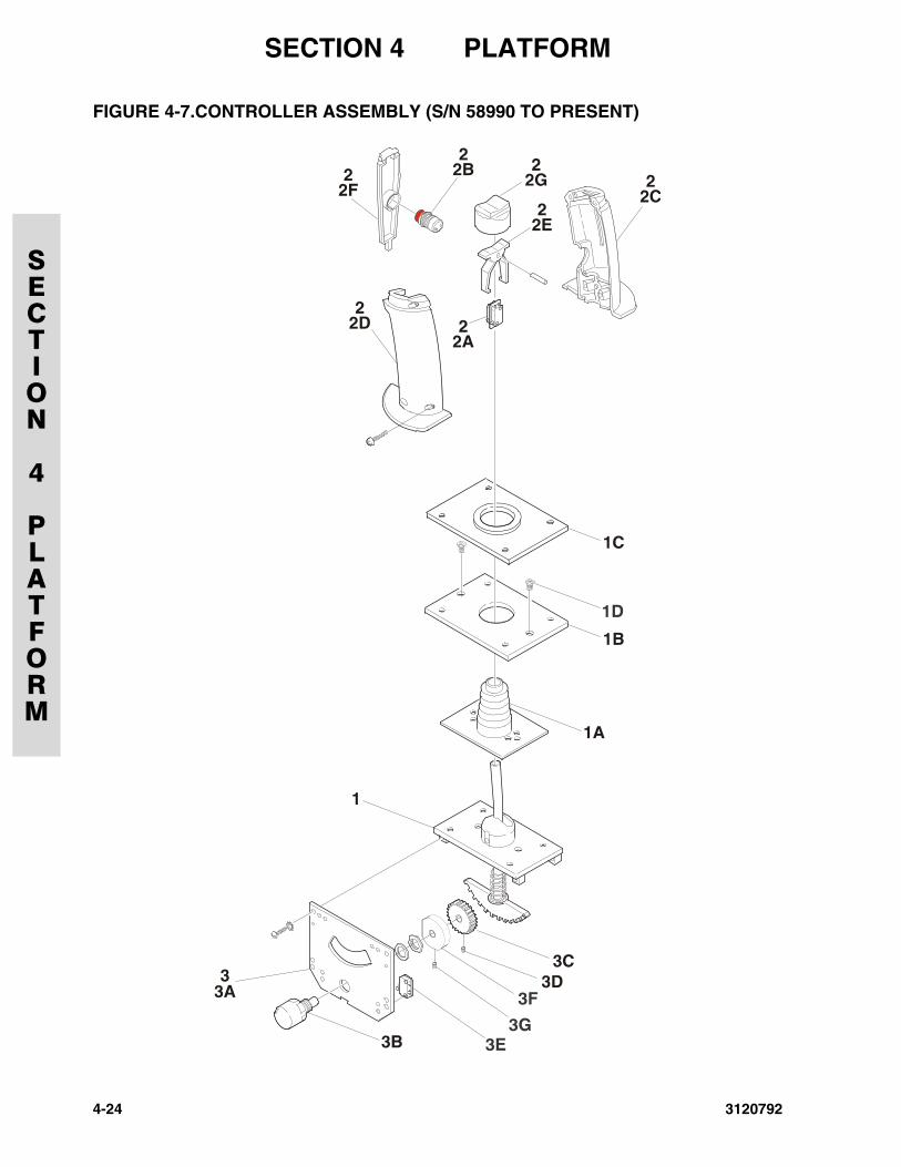
SECTION 4 PLATFORM
SECTION
4
PLATFORM
FIGURE 4-7.CONTROLLER ASSEMBLY (S/N 58990 TO PRESENT)
3F
3E3G
1D
4-24 3120792
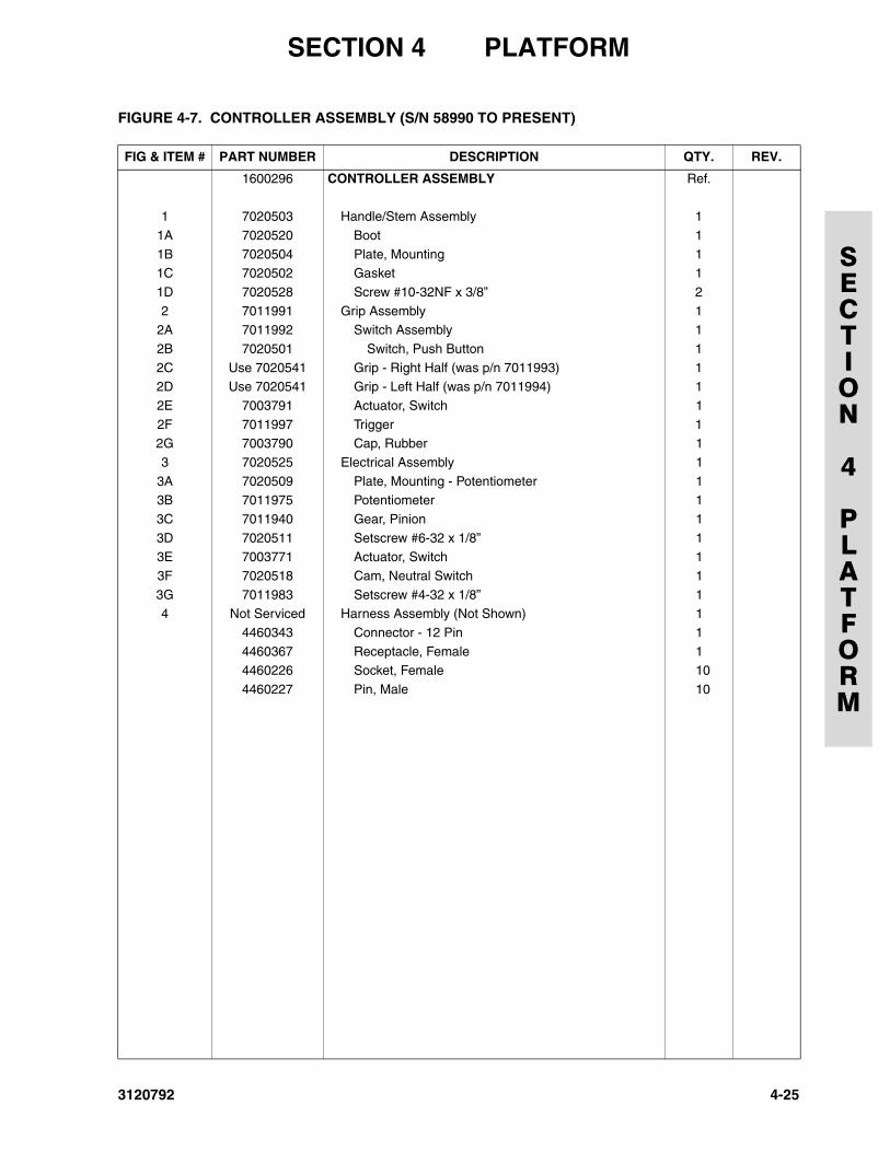
SECTION 4 PLATFORM
SECTION
4
PLATFORM
FIGURE 4-7. CONTROLLER ASSEMBLY (S/N 58990 TO PRESENT)
FIG & ITEM # PART NUMBER DESCRIPTION QTY. REV.
1600296 CONTROLLER ASSEMBLY Ref.
1 7020503 Handle/Stem Assembly 1
1A 7020520 Boot 1
1B 7020504 Plate, Mounting 11C 7020502 Gasket 1
1D 7020528 Screw #10-32NF x 3/8” 2
2 7011991 Grip Assembly 12A 7011992 Switch Assembly 1
2B 7020501 Switch, Push Button 1
2C Use 7020541 Grip - Right Half (was p/n 7011993) 12D Use 7020541 Grip - Left Half (was p/n 7011994) 1
2E 7003791 Actuator, Switch 1
2F 7011997 Trigger 12G 7003790 Cap, Rubber 1
3 7020525 Electrical Assembly 1
3A 7020509 Plate, Mounting - Potentiometer 13B 7011975 Potentiometer 1
3C 7011940 Gear, Pinion 1
3D 7020511 Setscrew #6-32 x 1/8” 13E 7003771 Actuator, Switch 1
3F 7020518 Cam, Neutral Switch 1
3G 7011983 Setscrew #4-32 x 1/8” 14 Not Serviced Harness Assembly (Not Shown) 1
4460343 Connector - 12 Pin 1
4460367 Receptacle, Female 14460226 Socket, Female 10
4460227 Pin, Male 10
3120792 4-25
SECTION 4 PLATFORM
SECTION
4
PLATFORM
FIGURE 4-7. CONTROLLER ASSEMBLY (S/N 58990 TO PRESENT) (CONTINUED)
FIG & ITEM # PART NUMBER DESCRIPTION QTY. REV.
4-26 3120792
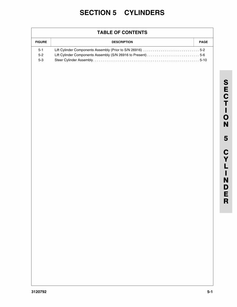
3120792
SECTION 5 CYLINDERS
SECTION
5
CYLINDER
TABLE OF CONTENTS
FIGURE DESCRIPTION PAGE
5-1 Lift Cylinder Components Assembly (Prior to S/N 26916) . . . . . . . . . . . . . . . . . . . . . . . . . . . . . 5-25-2 Lift Cylinder Components Assembly (S/N 26916 to Present) . . . . . . . . . . . . . . . . . . . . . . . . . . . 5-6
5-3 Steer Cylinder Assembly. . . . . . . . . . . . . . . . . . . . . . . . . . . . . . . . . . . . . . . . . . . . . . . . . . . . . . . 5-10
5-1
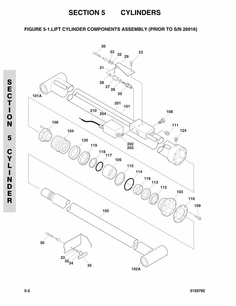
SECTION 5 CYLINDERS
SECTION
5
CYLINDER
FIGURE 5-1.LIFT CYLINDER COMPONENTS ASSEMBLY (PRIOR TO S/N 26916)
106
101A
101201
210
202203
108
111124
109
2526
2728
31
30
2923
120
104
119
102
102A
30
333234 35
118117
105
103
110
115
114
116113
112
204
3332
5-2 3120792
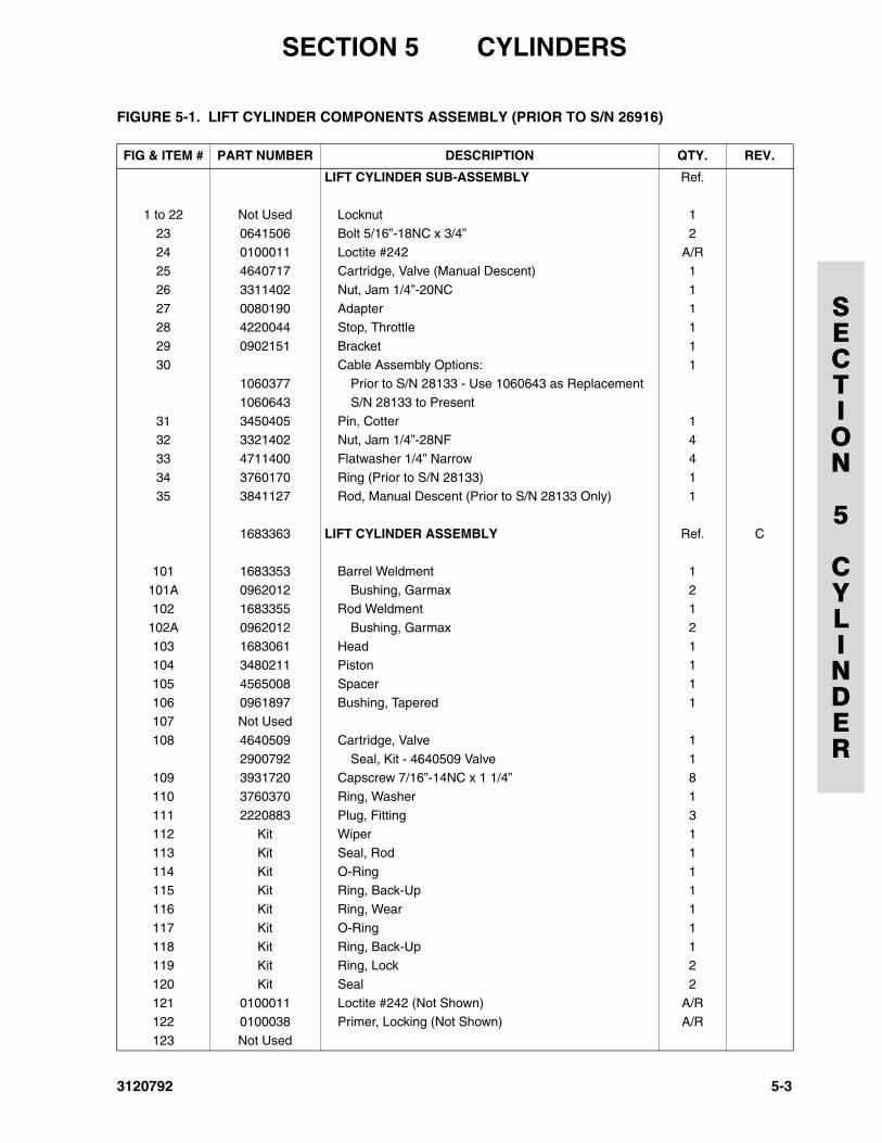
SECTION 5 CYLINDERS
SECTION
5
CYLINDER
FIGURE 5-1. LIFT CYLINDER COMPONENTS ASSEMBLY (PRIOR TO S/N 26916)
FIG & ITEM # PART NUMBER DESCRIPTION QTY. REV.
LIFT CYLINDER SUB-ASSEMBLY Ref.
1 to 22 Not Used Locknut 1
23 0641506 Bolt 5/16”-18NC x 3/4” 2
24 0100011 Loctite #242 A/R25 4640717 Cartridge, Valve (Manual Descent) 1
26 3311402 Nut, Jam 1/4”-20NC 1
27 0080190 Adapter 128 4220044 Stop, Throttle 1
29 0902151 Bracket 1
30 Cable Assembly Options: 11060377 Prior to S/N 28133 - Use 1060643 as Replacement
1060643 S/N 28133 to Present
31 3450405 Pin, Cotter 132 3321402 Nut, Jam 1/4”-28NF 4
33 4711400 Flatwasher 1/4” Narrow 4
34 3760170 Ring (Prior to S/N 28133) 135 3841127 Rod, Manual Descent (Prior to S/N 28133 Only) 1
1683363 LIFT CYLINDER ASSEMBLY Ref. C
101 1683353 Barrel Weldment 1
101A 0962012 Bushing, Garmax 2102 1683355 Rod Weldment 1
102A 0962012 Bushing, Garmax 2
103 1683061 Head 1104 3480211 Piston 1
105 4565008 Spacer 1
106 0961897 Bushing, Tapered 1107 Not Used
108 4640509 Cartridge, Valve 1
2900792 Seal, Kit - 4640509 Valve 1109 3931720 Capscrew 7/16”-14NC x 1 1/4” 8
110 3760370 Ring, Washer 1
111 2220883 Plug, Fitting 3112 Kit Wiper 1
113 Kit Seal, Rod 1
114 Kit O-Ring 1115 Kit Ring, Back-Up 1
116 Kit Ring, Wear 1
117 Kit O-Ring 1
118 Kit Ring, Back-Up 1119 Kit Ring, Lock 2
120 Kit Seal 2
121 0100011 Loctite #242 (Not Shown) A/R122 0100038 Primer, Locking (Not Shown) A/R
123 Not Used
3120792 5-3
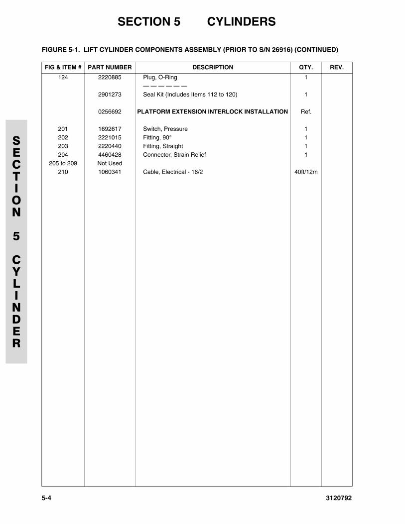
SECTION 5 CYLINDERS
SECTION
5
CYLINDER
124 2220885 Plug, O-Ring 1— — — — — —
2901273 Seal Kit (Includes Items 112 to 120) 1
0256692 PLATFORM EXTENSION INTERLOCK INSTALLATION Ref.
201 1692617 Switch, Pressure 1
202 2221015 Fitting, 90° 1203 2220440 Fitting, Straight 1
204 4460428 Connector, Strain Relief 1
205 to 209 Not Used210 1060341 Cable, Electrical - 16/2 40ft/12m
FIGURE 5-1. LIFT CYLINDER COMPONENTS ASSEMBLY (PRIOR TO S/N 26916) (CONTINUED)
FIG & ITEM # PART NUMBER DESCRIPTION QTY. REV.
5-4 3120792

SECTION 5 CYLINDERS
SECTION
5
CYLINDER
FIGURE 5-1. LIFT CYLINDER COMPONENTS ASSEMBLY (PRIOR TO S/N 26916) (CONTINUED)
FIG & ITEM # PART NUMBER DESCRIPTION QTY. REV.
3120792 5-5
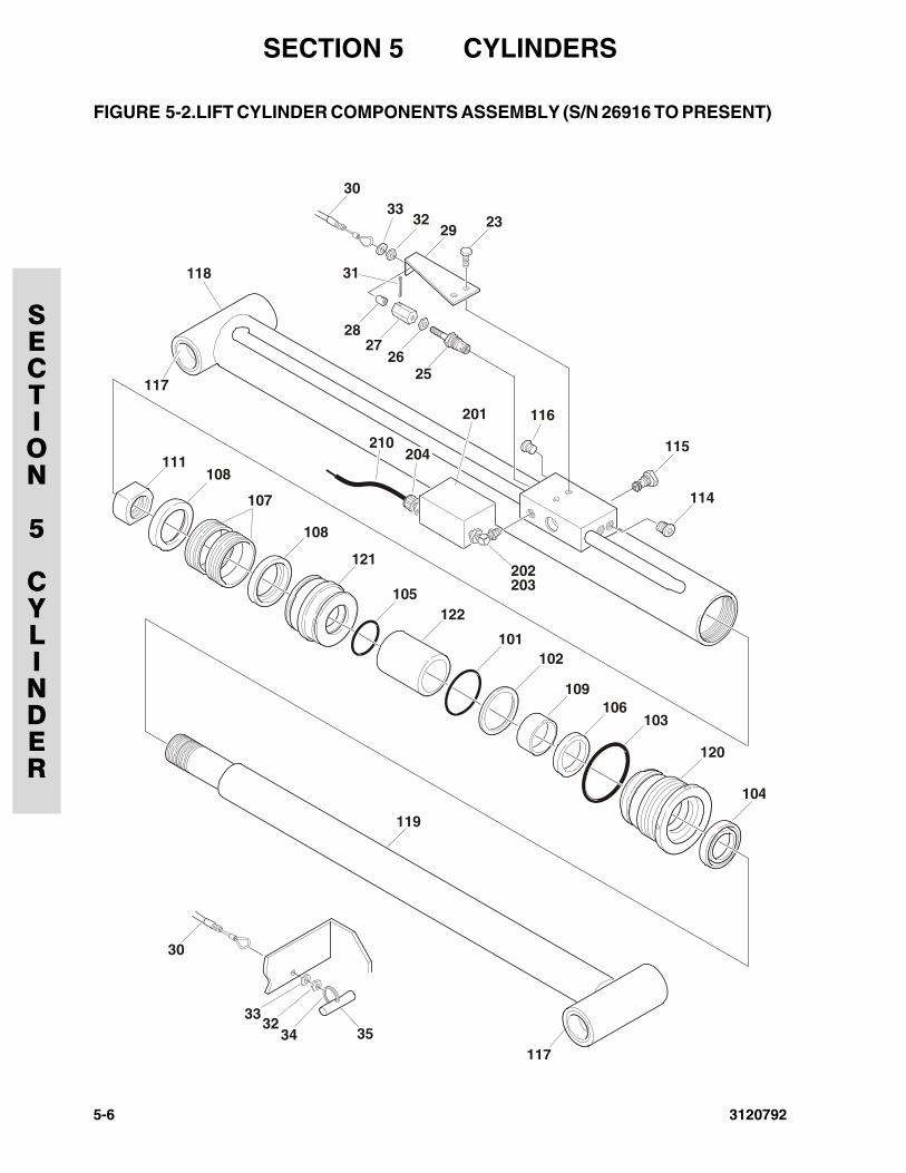
SECTION 5 CYLINDERS
SECTION
5
CYLINDER
FIGURE 5-2.LIFT CYLINDER COMPONENTS ASSEMBLY (S/N 26916 TO PRESENT)
117
118
116
111
108
108
106
121
105122
101102
109
107
103
120
104
114
115
2526
2728
31
30
29 23
119
117
30
3332
34 35
3332
201
210
202203
204
5-6 3120792
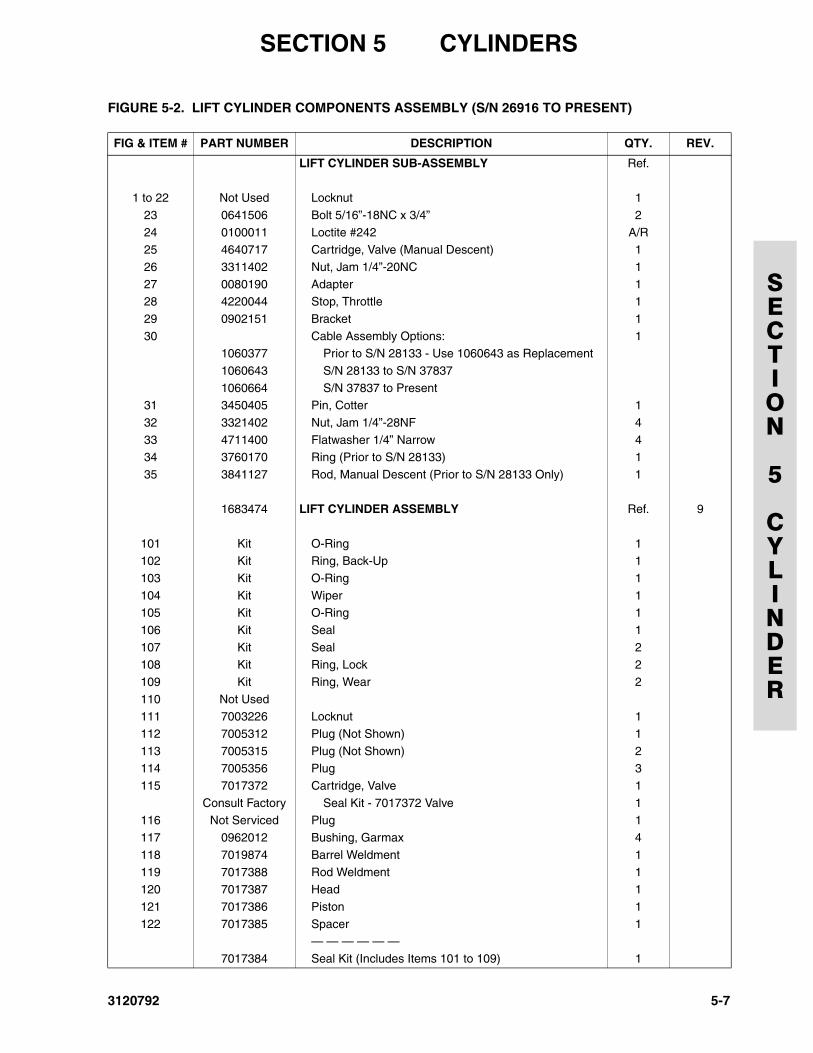
SECTION 5 CYLINDERS
SECTION
5
CYLINDER
FIGURE 5-2. LIFT CYLINDER COMPONENTS ASSEMBLY (S/N 26916 TO PRESENT)
FIG & ITEM # PART NUMBER DESCRIPTION QTY. REV.
LIFT CYLINDER SUB-ASSEMBLY Ref.
1 to 22 Not Used Locknut 1
23 0641506 Bolt 5/16”-18NC x 3/4” 2
24 0100011 Loctite #242 A/R25 4640717 Cartridge, Valve (Manual Descent) 1
26 3311402 Nut, Jam 1/4”-20NC 1
27 0080190 Adapter 128 4220044 Stop, Throttle 1
29 0902151 Bracket 1
30 Cable Assembly Options: 11060377 Prior to S/N 28133 - Use 1060643 as Replacement
1060643 S/N 28133 to S/N 37837
1060664 S/N 37837 to Present31 3450405 Pin, Cotter 1
32 3321402 Nut, Jam 1/4”-28NF 4
33 4711400 Flatwasher 1/4” Narrow 434 3760170 Ring (Prior to S/N 28133) 1
35 3841127 Rod, Manual Descent (Prior to S/N 28133 Only) 1
1683474 LIFT CYLINDER ASSEMBLY Ref. 9
101 Kit O-Ring 1102 Kit Ring, Back-Up 1
103 Kit O-Ring 1
104 Kit Wiper 1105 Kit O-Ring 1
106 Kit Seal 1
107 Kit Seal 2108 Kit Ring, Lock 2
109 Kit Ring, Wear 2
110 Not Used111 7003226 Locknut 1
112 7005312 Plug (Not Shown) 1
113 7005315 Plug (Not Shown) 2114 7005356 Plug 3
115 7017372 Cartridge, Valve 1
Consult Factory Seal Kit - 7017372 Valve 1116 Not Serviced Plug 1
117 0962012 Bushing, Garmax 4
118 7019874 Barrel Weldment 1
119 7017388 Rod Weldment 1120 7017387 Head 1
121 7017386 Piston 1
122 7017385 Spacer 1— — — — — —
7017384 Seal Kit (Includes Items 101 to 109) 1
3120792 5-7
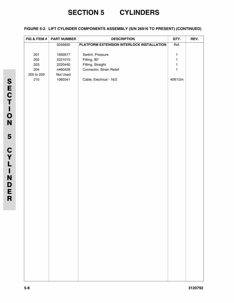
SECTION 5 CYLINDERS
SECTION
5
CYLINDER
0256692 PLATFORM EXTENSION INTERLOCK INSTALLATION Ref.
201 1692617 Switch, Pressure 1
202 2221015 Fitting, 90° 1
203 2220440 Fitting, Straight 1204 4460428 Connector, Strain Relief 1
205 to 209 Not Used
210 1060341 Cable, Electrical - 16/2 40ft/12m
FIGURE 5-2. LIFT CYLINDER COMPONENTS ASSEMBLY (S/N 26916 TO PRESENT) (CONTINUED)
FIG & ITEM # PART NUMBER DESCRIPTION QTY. REV.
5-8 3120792
SECTION 5 CYLINDERS
SECTION
5
CYLINDER
FIGURE 5-2. LIFT CYLINDER COMPONENTS ASSEMBLY (S/N 26916 TO PRESENT) (CONTINUED)
FIG & ITEM # PART NUMBER DESCRIPTION QTY. REV.
3120792 5-9
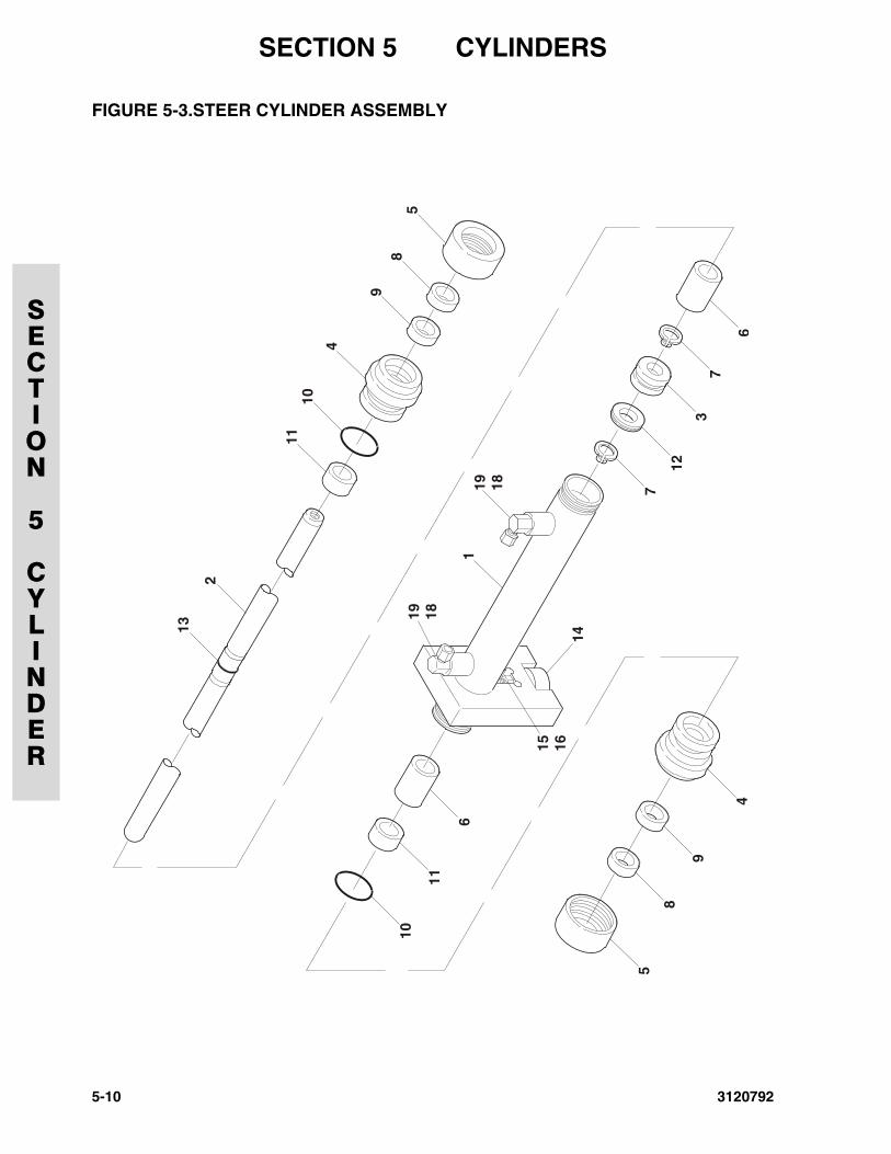
SECTION 5 CYLINDERS
SECTION
5
CYLINDER
FIGURE 5-3.STEER CYLINDER ASSEMBLY
5
10
11
6
8
9
4
19 18
15 1614
1
13
2
19 18 7
7
6
3
12
1110
4
98
5
5-10 3120792
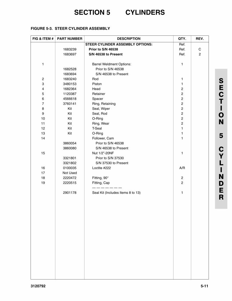
SECTION 5 CYLINDERS
SECTION
5
CYLINDER
FIGURE 5-3. STEER CYLINDER ASSEMBLY
FIG & ITEM # PART NUMBER DESCRIPTION QTY. REV.
STEER CYLINDER ASSEMBLY OPTIONS: Ref.1683239 Prior to S/N 46538 Ref. C
1683697 S/N 46538 to Present Ref. 2
1 Barrel Weldment Options: 11682528 Prior to S/N 46538
1683694 S/N 46538 to Present
2 1683240 Rod 13 3480153 Piston 1
4 1682364 Head 2
5 1120387 Retainer 26 4566618 Spacer 2
7 3760141 Ring, Retaining 2
8 Kit Seal, Wiper 29 Kit Seal, Rod 2
10 Kit O-Ring 2
11 Kit Ring, Wear 212 Kit T-Seal 1
13 Kit O-Ring 1
14 Follower, Cam 13860054 Prior to S/N 46538
3860080 S/N 46538 to Present
15 Nut 1/2”-20NF 13321801 Prior to S/N 37530
3321802 S/N 37530 to Present
16 0100035 Loctite #222 A/R17 Not Used
18 2220472 Fitting, 90° 2
19 2220515 Fitting, Cap 2— — — — — — —
2901178 Seal Kit (Includes Items 8 to 13) 1
3120792 5-11
SECTION 5 CYLINDERS
SECTION
5
CYLINDER
FIGURE 5-3. STEER CYLINDER ASSEMBLY (CONTINUED)
FIG & ITEM # PART NUMBER DESCRIPTION QTY. REV.
5-12 3120792
3120792
SECTION 6 HYDRAULIC
SECTION
6
HYDRAULIC
TABLE OF CONTENTS
FIGURE DESCRIPTION PAGE
6-1 Hydraulic Diagram - Standard. . . . . . . . . . . . . . . . . . . . . . . . . . . . . . . . . . . . . . . . . . . . . . . . . . . 6-26-2 Hydraulic Diagram List . . . . . . . . . . . . . . . . . . . . . . . . . . . . . . . . . . . . . . . . . . . . . . . . . . . . . . . . 6-6
6-1
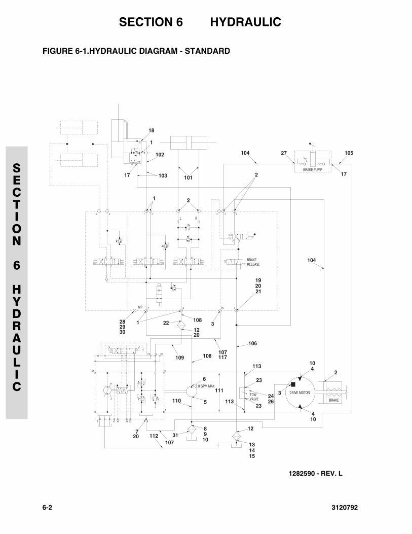
SECTION 6 HYDRAULIC
SECTION
6
HYDRAULIC
FIGURE 6-1.HYDRAULIC DIAGRAM - STANDARD
1282590 - REV. L
6-2 3120792
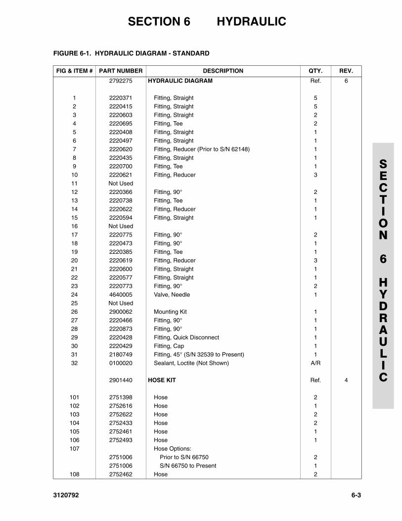
SECTION 6 HYDRAULIC
SECTION
6
HYDRAULIC
FIGURE 6-1. HYDRAULIC DIAGRAM - STANDARD
FIG & ITEM # PART NUMBER DESCRIPTION QTY. REV.
2792275 HYDRAULIC DIAGRAM Ref. 6
1 2220371 Fitting, Straight 5
2 2220415 Fitting, Straight 5
3 2220603 Fitting, Straight 24 2220695 Fitting, Tee 2
5 2220408 Fitting, Straight 1
6 2220497 Fitting, Straight 17 2220620 Fitting, Reducer (Prior to S/N 62148) 1
8 2220435 Fitting, Straight 1
9 2220700 Fitting, Tee 110 2220621 Fitting, Reducer 3
11 Not Used
12 2220366 Fitting, 90° 213 2220738 Fitting, Tee 1
14 2220622 Fitting, Reducer 1
15 2220594 Fitting, Straight 116 Not Used
17 2220775 Fitting, 90° 2
18 2220473 Fitting, 90° 119 2220385 Fitting, Tee 1
20 2220619 Fitting, Reducer 3
21 2220600 Fitting, Straight 122 2220577 Fitting, Straight 1
23 2220773 Fitting, 90° 2
24 4640005 Valve, Needle 125 Not Used
26 2900062 Mounting Kit 1
27 2220466 Fitting, 90° 128 2220873 Fitting, 90° 1
29 2220428 Fitting, Quick Disconnect 1
30 2220429 Fitting, Cap 131 2180749 Fitting, 45° (S/N 32539 to Present) 1
32 0100020 Sealant, Loctite (Not Shown) A/R
2901440 HOSE KIT Ref. 4
101 2751398 Hose 2102 2752616 Hose 1
103 2752622 Hose 2
104 2752433 Hose 2
105 2752461 Hose 1106 2752493 Hose 1
107 Hose Options:
2751006 Prior to S/N 66750 22751006 S/N 66750 to Present 1
108 2752462 Hose 2
3120792 6-3
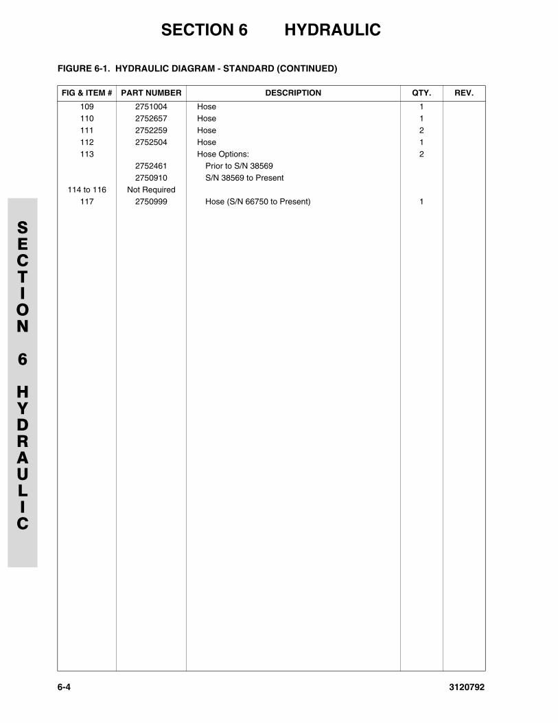
SECTION 6 HYDRAULIC
SECTION
6
HYDRAULIC
109 2751004 Hose 1110 2752657 Hose 1
111 2752259 Hose 2
112 2752504 Hose 1
113 Hose Options: 22752461 Prior to S/N 38569
2750910 S/N 38569 to Present
114 to 116 Not Required117 2750999 Hose (S/N 66750 to Present) 1
FIGURE 6-1. HYDRAULIC DIAGRAM - STANDARD (CONTINUED)
FIG & ITEM # PART NUMBER DESCRIPTION QTY. REV.
6-4 3120792
SECTION 6 HYDRAULIC
SECTION
6
HYDRAULIC
FIGURE 6-1. HYDRAULIC DIAGRAM - STANDARD (CONTINUED)
FIG & ITEM # PART NUMBER DESCRIPTION QTY. REV.
3120792 6-5
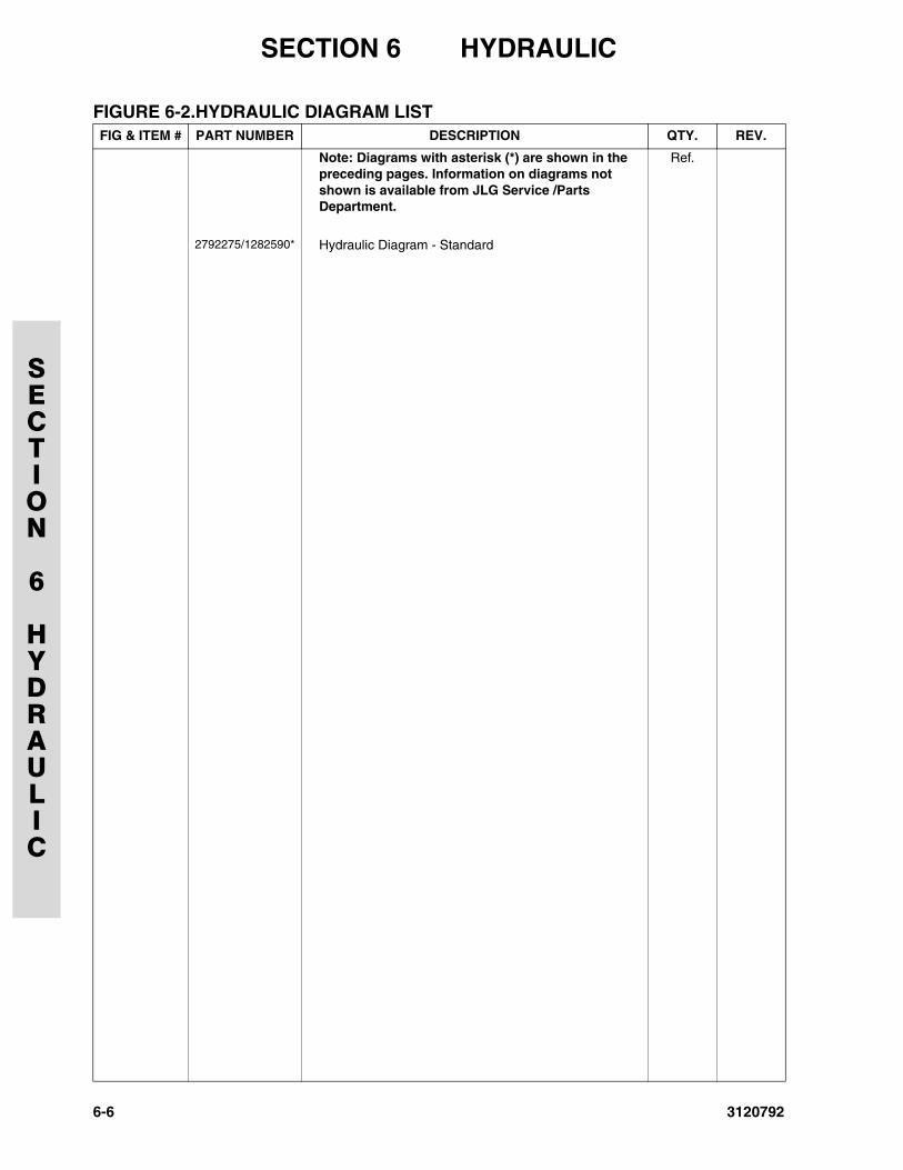
SECTION 6 HYDRAULIC
SECTION
6
HYDRAULIC
FIGURE 6-2.HYDRAULIC DIAGRAM LISTFIG & ITEM # PART NUMBER DESCRIPTION QTY. REV.
Note: Diagrams with asterisk (*) are shown in the preceding pages. Information on diagrams not shown is available from JLG Service /Parts Department.
Ref.
2792275/1282590* Hydraulic Diagram - Standard
6-6 3120792
3120792
SECTION 7 ELECTRICAL
SECTION
7
ELECTRICAL
TABLE OF CONTENTS
FIGURE DESCRIPTION PAGE
7-1 ELECTRICAL DIAGRAM LIST . . . . . . . . . . . . . . . . . . . . . . . . . . . . . . . . . . . . . . . . . . . . . . . . . . 7-27-2 ELECTRICAL SCHEMATIC - VANGUARD. . . . . . . . . . . . . . . . . . . . . . . . . . . . . . . . . . . . . . . . . 7-4
7-3 ELECTRICAL SCHEMATIC - YANMAR . . . . . . . . . . . . . . . . . . . . . . . . . . . . . . . . . . . . . . . . . . . 7-6
7-4 HARNESS AND CABLE ASSEMBLIES . . . . . . . . . . . . . . . . . . . . . . . . . . . . . . . . . . . . . . . . . . . 7-8
7-1
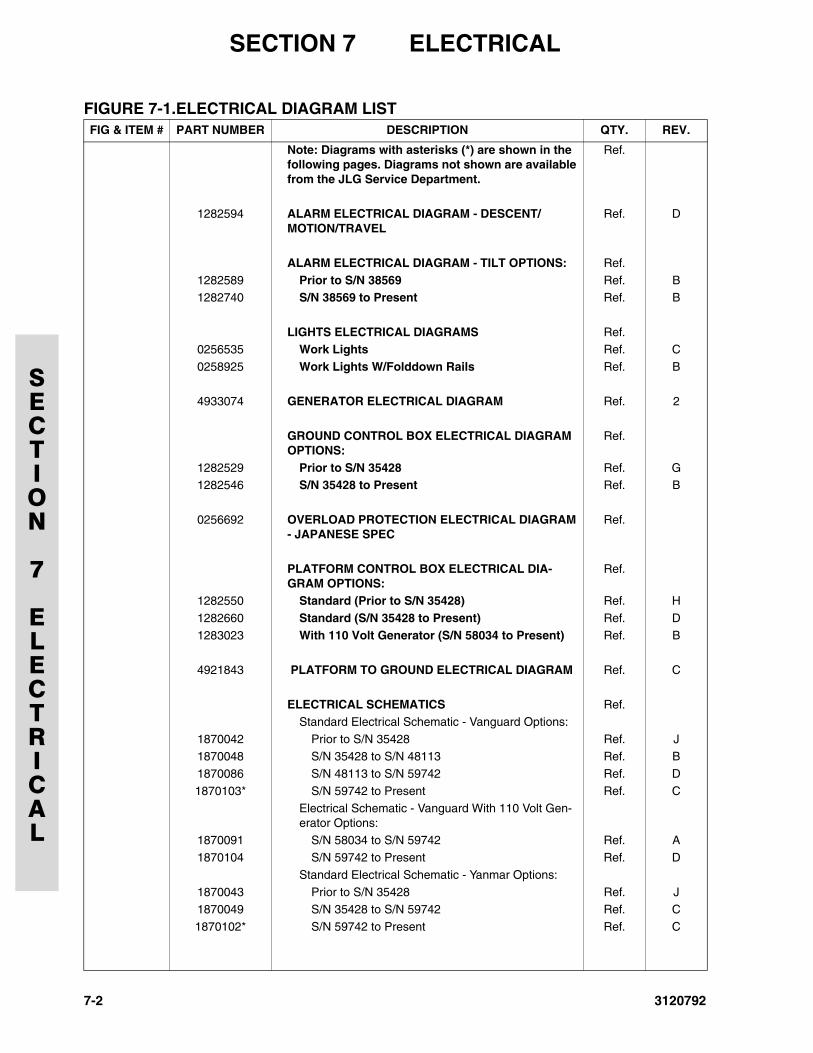
SECTION 7 ELECTRICAL
SECTION
7
ELECTRICAL
FIGURE 7-1.ELECTRICAL DIAGRAM LISTFIG & ITEM # PART NUMBER DESCRIPTION QTY. REV.
Note: Diagrams with asterisks (*) are shown in the following pages. Diagrams not shown are available from the JLG Service Department.
Ref.
1282594 ALARM ELECTRICAL DIAGRAM - DESCENT/MOTION/TRAVEL
Ref. D
ALARM ELECTRICAL DIAGRAM - TILT OPTIONS: Ref.
1282589 Prior to S/N 38569 Ref. B1282740 S/N 38569 to Present Ref. B
LIGHTS ELECTRICAL DIAGRAMS Ref.0256535 Work Lights Ref. C
0258925 Work Lights W/Folddown Rails Ref. B
4933074 GENERATOR ELECTRICAL DIAGRAM Ref. 2
GROUND CONTROL BOX ELECTRICAL DIAGRAM OPTIONS:
Ref.
1282529 Prior to S/N 35428 Ref. G1282546 S/N 35428 to Present Ref. B
0256692 OVERLOAD PROTECTION ELECTRICAL DIAGRAM - JAPANESE SPEC
Ref.
PLATFORM CONTROL BOX ELECTRICAL DIA-GRAM OPTIONS:
Ref.
1282550 Standard (Prior to S/N 35428) Ref. H
1282660 Standard (S/N 35428 to Present) Ref. D
1283023 With 110 Volt Generator (S/N 58034 to Present) Ref. B
4921843 PLATFORM TO GROUND ELECTRICAL DIAGRAM Ref. C
ELECTRICAL SCHEMATICS Ref.
Standard Electrical Schematic - Vanguard Options:
1870042 Prior to S/N 35428 Ref. J1870048 S/N 35428 to S/N 48113 Ref. B
1870086 S/N 48113 to S/N 59742 Ref. D
1870103* S/N 59742 to Present Ref. CElectrical Schematic - Vanguard With 110 Volt Gen-erator Options:
1870091 S/N 58034 to S/N 59742 Ref. A
1870104 S/N 59742 to Present Ref. D
Standard Electrical Schematic - Yanmar Options:
1870043 Prior to S/N 35428 Ref. J1870049 S/N 35428 to S/N 59742 Ref. C
1870102* S/N 59742 to Present Ref. C
7-2 3120792
SECTION 7 ELECTRICAL
SECTION
7
ELECTRICAL
FIGURE 7-1.ELECTRICAL DIAGRAM LISTFIG & ITEM # PART NUMBER DESCRIPTION QTY. REV.
3120792 7-3
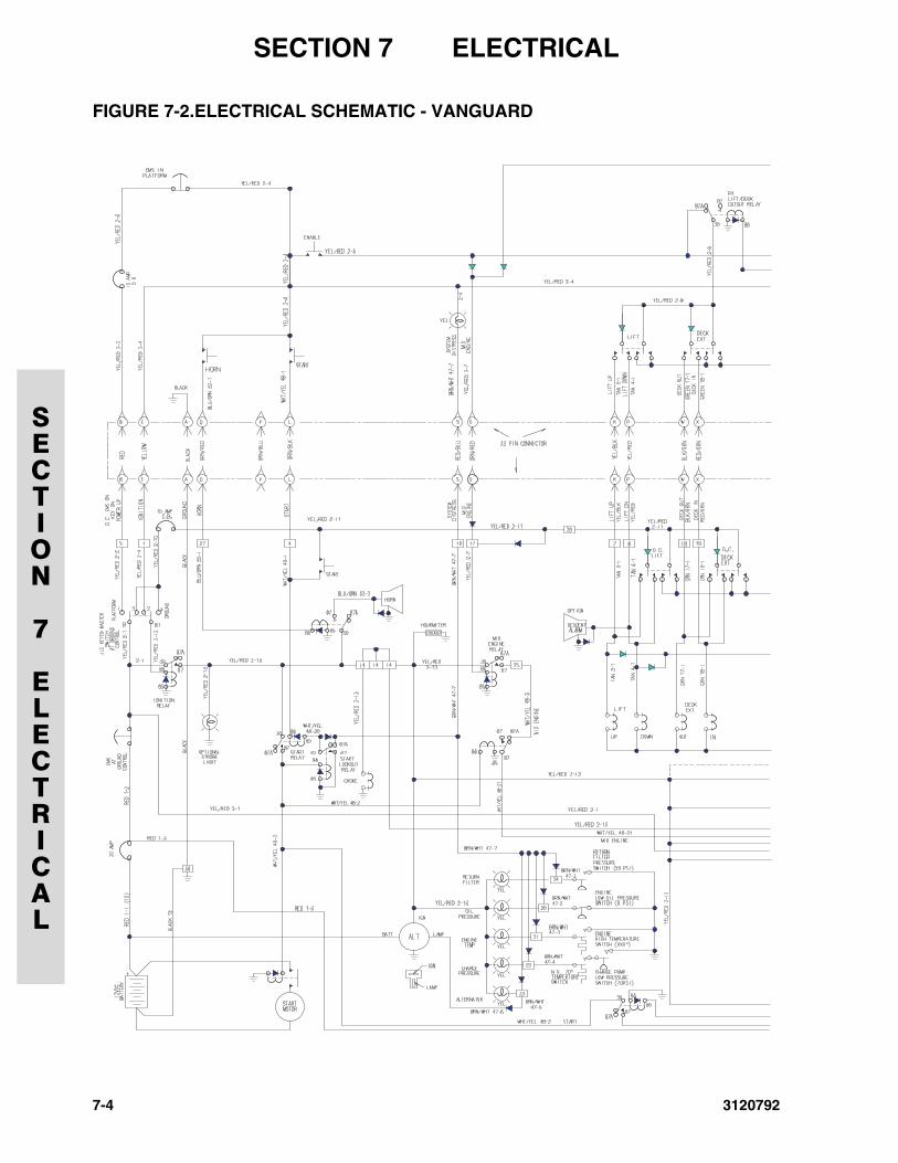
SECTION 7 ELECTRICAL
SECTION
7
ELECTRICAL
FIGURE 7-2.ELECTRICAL SCHEMATIC - VANGUARD
7-4 3120792
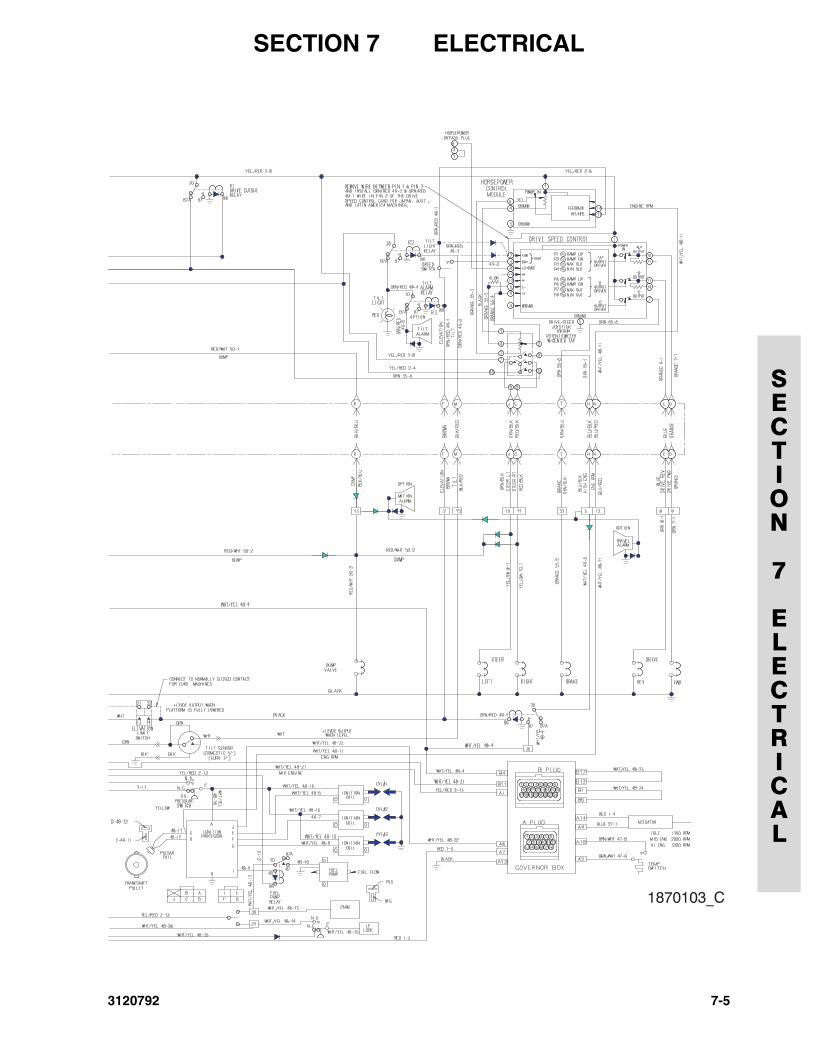
SECTION 7 ELECTRICAL
SECTION
7
ELECTRICAL
3120792 7-5
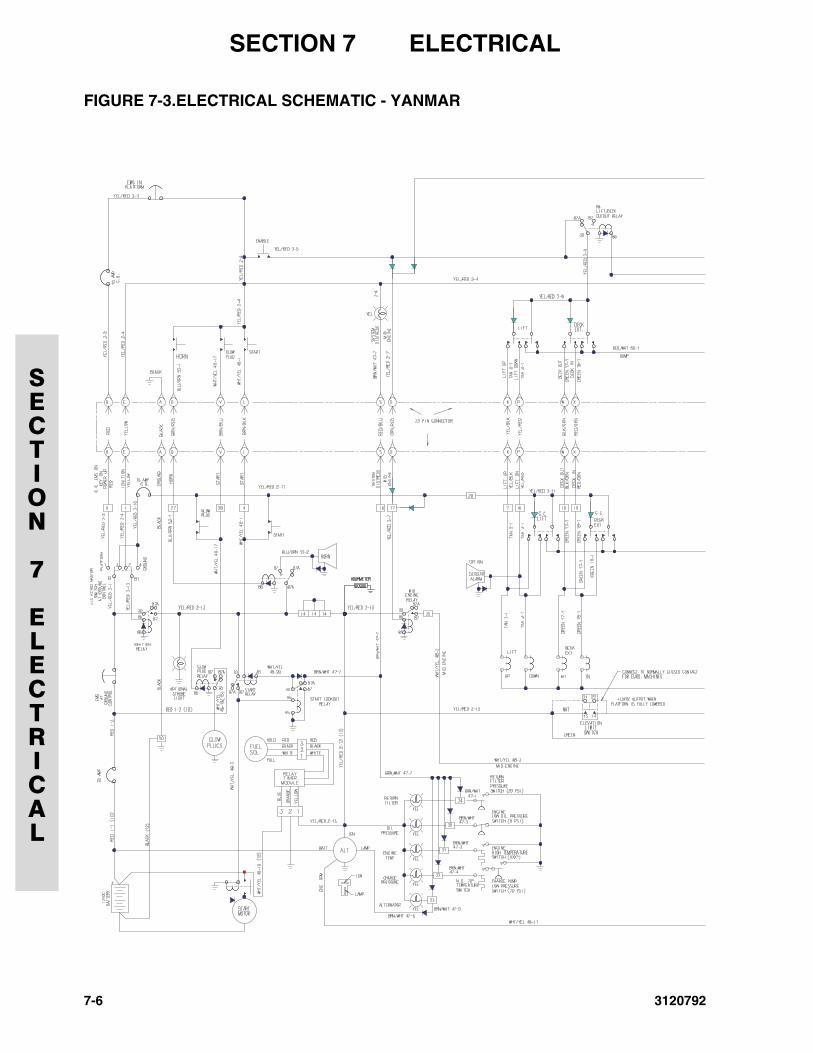
SECTION 7 ELECTRICAL
SECTION
7
ELECTRICAL
FIGURE 7-3.ELECTRICAL SCHEMATIC - YANMAR
7-6 3120792
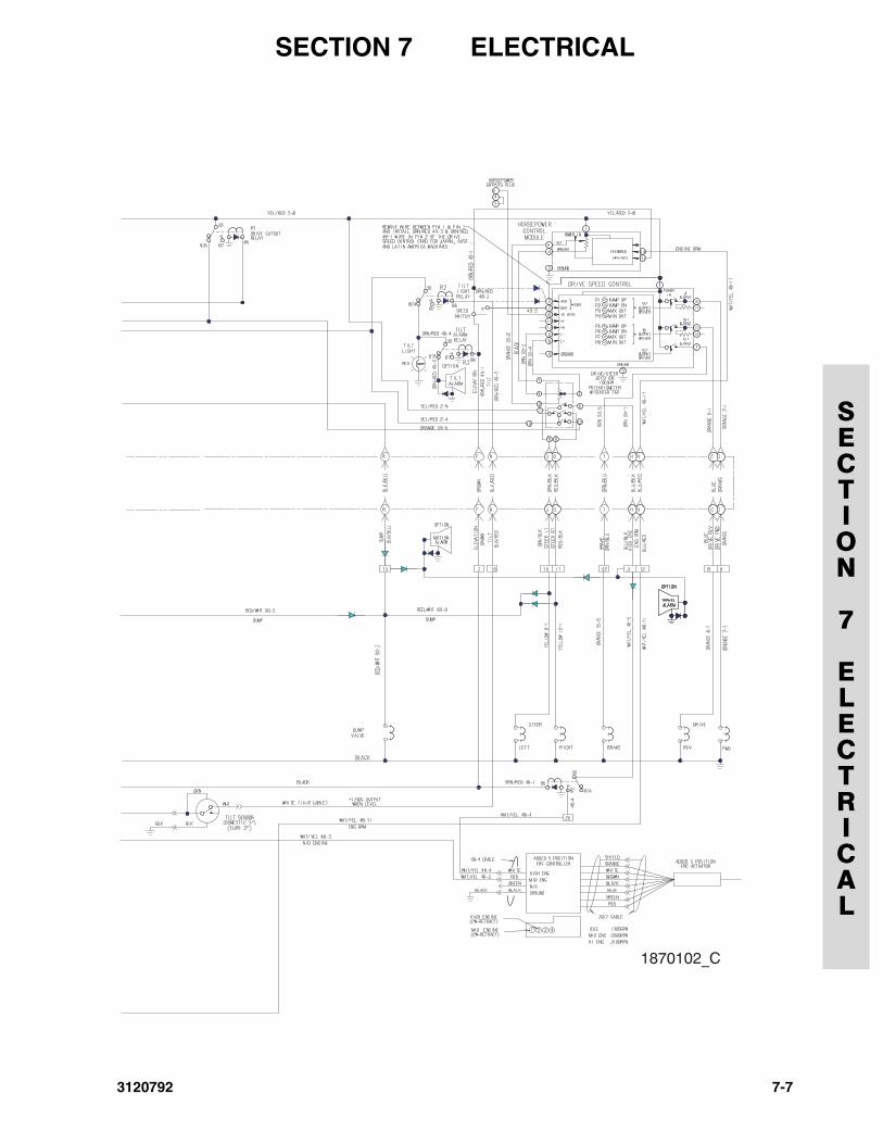
SECTION 7 ELECTRICAL
SECTION
7
ELECTRICAL
3120792 7-7
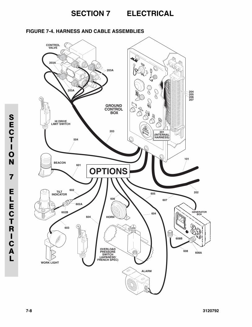
SECTION 7 ELECTRICAL
SECTION
7
ELECTRICAL
FIGURE 7-4. HARNESS AND CABLE ASSEMBLIES
7-8 3120792
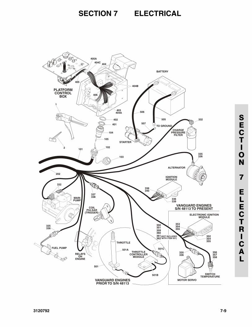
SECTION 7 ELECTRICAL
SECTION
7
ELECTRICAL
MAINPUMP
FUEL PUMP
RELAYSON
ENGINE
COIL PULSAR
(TRIGGER)
ALTERNATOR
VANGUARD ENGINESPRIOR TO S/N 48113
MOTOR SERVO
SWITCHTEMPERATURE
VANGUARD ENGINESS/N 48113 TO PRESENT
ELECTRONIC IGNITIONMODULE
CHARGEPRESSURE
FILTER
STARTER
TO GROUND
PLATFORMCONTROL
BOX
BATTERY
1
2 101102
103
104
105
202
332
332
335336
335336
337338
IGNITIONMODULE
336340
336339
353354355
352354355
356357358
335336
401
402
404
403404A
406
404B
404C
405
405A
505
506
507
361362
359360
350351
(NOT INCLUDED WITH ITEM 501)
THROTTLE
THROTTLECONTROLLER
MODULE
501A
501B
501
501C
3120792 7-9
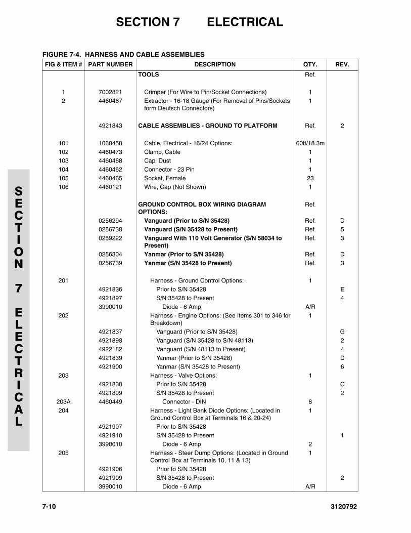
SECTION 7 ELECTRICAL
SECTION
7
ELECTRICAL
FIGURE 7-4. HARNESS AND CABLE ASSEMBLIESFIG & ITEM # PART NUMBER DESCRIPTION QTY. REV.
TOOLS Ref.
1 7002821 Crimper (For Wire to Pin/Socket Connections) 1
2 4460467 Extractor - 16-18 Gauge (For Removal of Pins/Sockets form Deutsch Connectors)
1
4921843 CABLE ASSEMBLIES - GROUND TO PLATFORM Ref. 2
101 1060458 Cable, Electrical - 16/24 Options: 60ft/18.3m
102 4460473 Clamp, Cable 1103 4460468 Cap, Dust 1
104 4460462 Connector - 23 Pin 1
105 4460465 Socket, Female 23106 4460121 Wire, Cap (Not Shown) 1
GROUND CONTROL BOX WIRING DIAGRAM OPTIONS:
Ref.
0256294 Vanguard (Prior to S/N 35428) Ref. D0256738 Vanguard (S/N 35428 to Present) Ref. 5
0259222 Vanguard With 110 Volt Generator (S/N 58034 to Present)
Ref. 3
0256304 Yanmar (Prior to S/N 35428) Ref. D
0256739 Yanmar (S/N 35428 to Present) Ref. 3
201 Harness - Ground Control Options: 1
4921836 Prior to S/N 35428 E4921897 S/N 35428 to Present 4
3990010 Diode - 6 Amp A/R
202 Harness - Engine Options: (See Items 301 to 346 for Breakdown)
1
4921837 Vanguard (Prior to S/N 35428) G4921898 Vanguard (S/N 35428 to S/N 48113) 2
4922182 Vanguard (S/N 48113 to Present) 4
4921839 Yanmar (Prior to S/N 35428) D4921900 Yanmar (S/N 35428 to Present) 6
203 Harness - Valve Options: 1
4921838 Prior to S/N 35428 C4921899 S/N 35428 to Present 2
203A 4460449 Connector - DIN 8
204 Harness - Light Bank Diode Options: (Located in Ground Control Box at Terminals 16 & 20-24)
1
4921907 Prior to S/N 35428
4921910 S/N 35428 to Present 13990010 Diode - 6 Amp 2
205 Harness - Steer Dump Options: (Located in Ground Control Box at Terminals 10, 11 & 13)
1
4921906 Prior to S/N 35428
4921909 S/N 35428 to Present 23990010 Diode - 6 Amp A/R
7-10 3120792
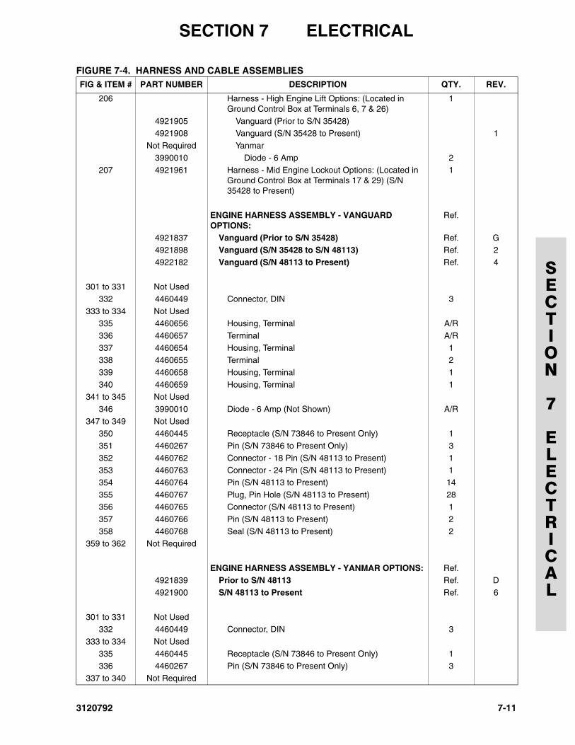
SECTION 7 ELECTRICAL
SECTION
7
ELECTRICAL
206 Harness - High Engine Lift Options: (Located in Ground Control Box at Terminals 6, 7 & 26)
1
4921905 Vanguard (Prior to S/N 35428)4921908 Vanguard (S/N 35428 to Present) 1
Not Required Yanmar
3990010 Diode - 6 Amp 2
207 4921961 Harness - Mid Engine Lockout Options: (Located in Ground Control Box at Terminals 17 & 29) (S/N 35428 to Present)
1
ENGINE HARNESS ASSEMBLY - VANGUARD OPTIONS:
Ref.
4921837 Vanguard (Prior to S/N 35428) Ref. G4921898 Vanguard (S/N 35428 to S/N 48113) Ref. 2
4922182 Vanguard (S/N 48113 to Present) Ref. 4
301 to 331 Not Used
332 4460449 Connector, DIN 3
333 to 334 Not Used335 4460656 Housing, Terminal A/R
336 4460657 Terminal A/R
337 4460654 Housing, Terminal 1338 4460655 Terminal 2
339 4460658 Housing, Terminal 1
340 4460659 Housing, Terminal 1341 to 345 Not Used
346 3990010 Diode - 6 Amp (Not Shown) A/R
347 to 349 Not Used350 4460445 Receptacle (S/N 73846 to Present Only) 1
351 4460267 Pin (S/N 73846 to Present Only) 3
352 4460762 Connector - 18 Pin (S/N 48113 to Present) 1353 4460763 Connector - 24 Pin (S/N 48113 to Present) 1
354 4460764 Pin (S/N 48113 to Present) 14
355 4460767 Plug, Pin Hole (S/N 48113 to Present) 28356 4460765 Connector (S/N 48113 to Present) 1
357 4460766 Pin (S/N 48113 to Present) 2
358 4460768 Seal (S/N 48113 to Present) 2359 to 362 Not Required
ENGINE HARNESS ASSEMBLY - YANMAR OPTIONS: Ref.4921839 Prior to S/N 48113 Ref. D
4921900 S/N 48113 to Present Ref. 6
301 to 331 Not Used332 4460449 Connector, DIN 3
333 to 334 Not Used
335 4460445 Receptacle (S/N 73846 to Present Only) 1336 4460267 Pin (S/N 73846 to Present Only) 3
337 to 340 Not Required
FIGURE 7-4. HARNESS AND CABLE ASSEMBLIESFIG & ITEM # PART NUMBER DESCRIPTION QTY. REV.
3120792 7-11
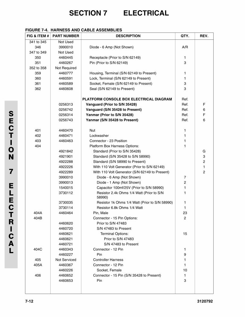
SECTION 7 ELECTRICAL
SECTION
7
ELECTRICAL
341 to 345 Not Used346 3990010 Diode - 6 Amp (Not Shown) A/R
347 to 349 Not Used
350 4460445 Receptacle (Prior to S/N 62149) 1
351 4460267 Pin (Prior to S/N 62149) 3352 to 358 Not Required
359 4460777 Housing, Terminal (S/N 62149 to Present) 1
360 4460591 Lock, Terminal (S/N 62149 to Present) 1361 4460589 Socket, Female (S/N 62149 to Present) 3
362 4460608 Seal (S/N 62149 to Present) 3
PLATFORM CONSOLE BOX ELECTRICAL DIAGRAM Ref.
0256313 Vanguard (Prior to S/N 35428) Ref. F
0256742 Vanguard (S/N 35428 to Present) Ref. 60256314 Yanmar (Prior to S/N 35428) Ref. F
0256743 Yanmar (S/N 35428 to Present) Ref. 6
401 4460470 Nut 1
402 4460471 Lockwasher 1
403 4460463 Connector - 23 Position 1404 Platform Box Harness Options: 1
4921842 Standard (Prior to S/N 35428) G
4921901 Standard (S/N 35428 to S/N 58990) 34922288 Standard (S/N 58990 to Present) 2
4922226 With 110 Volt Generator (Prior to S/N 62149) 1
4922289 With 110 Volt Generator (S/N 62149 to Present) 23990010 Diode - 6 Amp (Not Shown) 7
3990013 Diode - 1 Amp (Not Shown) 2
1540015 Capacitor 100mf/25V (Prior to S/N 58990) 13730112 Resistor 2.4k Ohms 1/4 Watt (Prior to S/N
58990)1
3730035 Resistor 1k Ohms 1/4 Watt (Prior to S/N 58990) 1
3730114 Resistor 6.8k Ohms 1/4 Watt 1
404A 4460464 Pin, Male 23404B Connector - 15 Pin Options: 2
4460620 Prior to S/N 47483
4460720 S/N 47483 to Present4460621 Terminal Options: 15
4460621 Prior to S/N 47483
4460721 S/N 47483 to Present404C 4460343 Connector - 12 Pin 1
4460227 Pin 9
405 Not Serviced Controller Harness 1
405A 4460367 Connector - 12 Pin 14460226 Socket, Female 10
406 4460652 Connector - 15 Pin (S/N 35428 to Present) 1
4460653 Pin 3
FIGURE 7-4. HARNESS AND CABLE ASSEMBLIESFIG & ITEM # PART NUMBER DESCRIPTION QTY. REV.
7-12 3120792
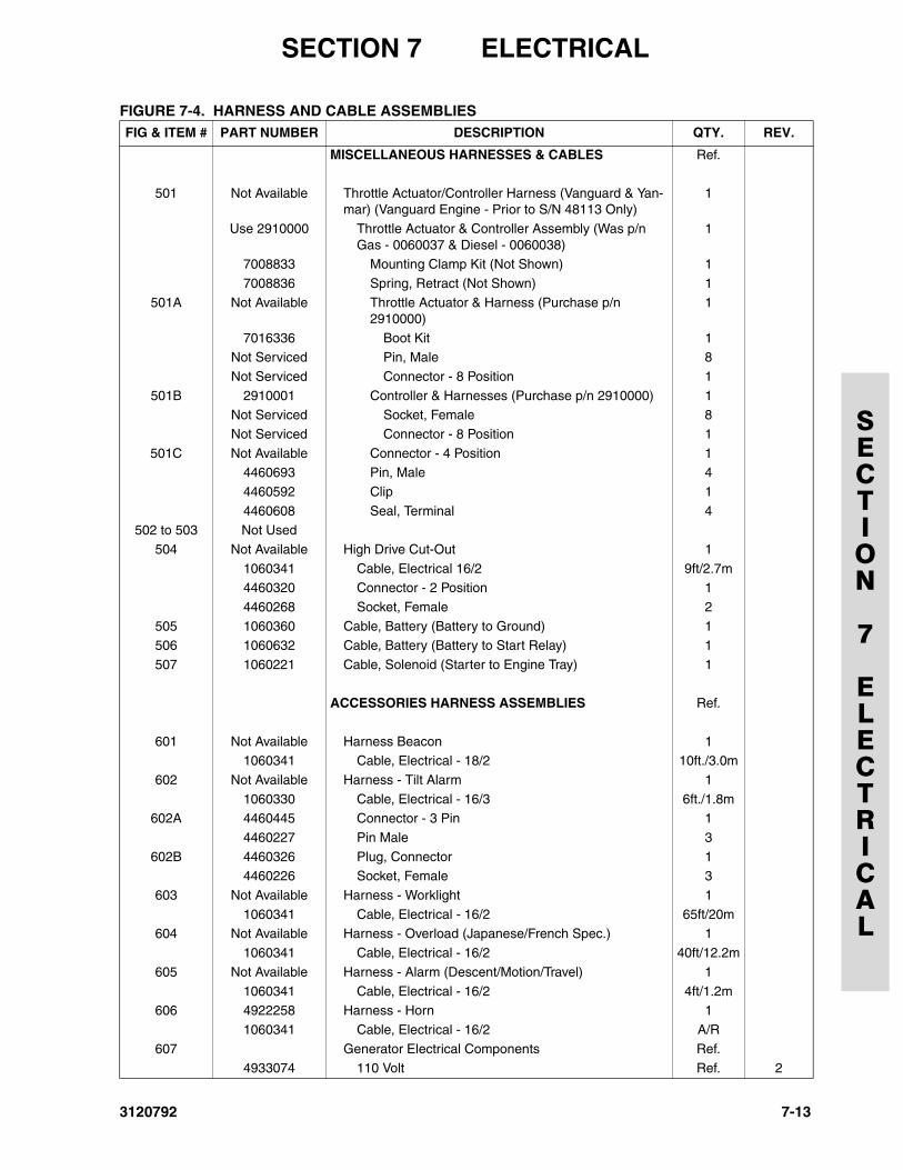
SECTION 7 ELECTRICAL
SECTION
7
ELECTRICAL
MISCELLANEOUS HARNESSES & CABLES Ref.
501 Not Available Throttle Actuator/Controller Harness (Vanguard & Yan-mar) (Vanguard Engine - Prior to S/N 48113 Only)
1
Use 2910000 Throttle Actuator & Controller Assembly (Was p/n Gas - 0060037 & Diesel - 0060038)
1
7008833 Mounting Clamp Kit (Not Shown) 1
7008836 Spring, Retract (Not Shown) 1
501A Not Available Throttle Actuator & Harness (Purchase p/n 2910000)
1
7016336 Boot Kit 1Not Serviced Pin, Male 8
Not Serviced Connector - 8 Position 1
501B 2910001 Controller & Harnesses (Purchase p/n 2910000) 1Not Serviced Socket, Female 8
Not Serviced Connector - 8 Position 1
501C Not Available Connector - 4 Position 14460693 Pin, Male 4
4460592 Clip 1
4460608 Seal, Terminal 4502 to 503 Not Used
504 Not Available High Drive Cut-Out 1
1060341 Cable, Electrical 16/2 9ft/2.7m4460320 Connector - 2 Position 1
4460268 Socket, Female 2
505 1060360 Cable, Battery (Battery to Ground) 1506 1060632 Cable, Battery (Battery to Start Relay) 1
507 1060221 Cable, Solenoid (Starter to Engine Tray) 1
ACCESSORIES HARNESS ASSEMBLIES Ref.
601 Not Available Harness Beacon 11060341 Cable, Electrical - 18/2 10ft./3.0m
602 Not Available Harness - Tilt Alarm 1
1060330 Cable, Electrical - 16/3 6ft./1.8m602A 4460445 Connector - 3 Pin 1
4460227 Pin Male 3
602B 4460326 Plug, Connector 14460226 Socket, Female 3
603 Not Available Harness - Worklight 1
1060341 Cable, Electrical - 16/2 65ft/20m604 Not Available Harness - Overload (Japanese/French Spec.) 1
1060341 Cable, Electrical - 16/2 40ft/12.2m
605 Not Available Harness - Alarm (Descent/Motion/Travel) 1
1060341 Cable, Electrical - 16/2 4ft/1.2m606 4922258 Harness - Horn 1
1060341 Cable, Electrical - 16/2 A/R
607 Generator Electrical Components Ref.4933074 110 Volt Ref. 2
FIGURE 7-4. HARNESS AND CABLE ASSEMBLIESFIG & ITEM # PART NUMBER DESCRIPTION QTY. REV.
3120792 7-13
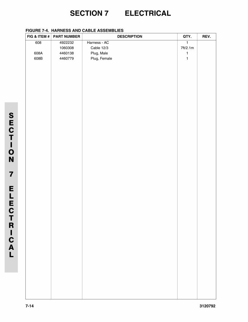
SECTION 7 ELECTRICAL
SECTION
7
ELECTRICAL
608 4922232 Harness - AC 11060308 Cable 12/3 7ft/2.1m
608A 4460138 Plug, Male 1
608B 4460779 Plug, Female 1
FIGURE 7-4. HARNESS AND CABLE ASSEMBLIESFIG & ITEM # PART NUMBER DESCRIPTION QTY. REV.
7-14 3120792
3120792
SECTION 8 DECALS
SECTION
8
DECALS
TABLE OF CONTENTS
FIGURE DESCRIPTION PAGE
8-1 Decals Installations . . . . . . . . . . . . . . . . . . . . . . . . . . . . . . . . . . . . . . . . . . . . . . . . . . . . . . . . . . . 8-2
8-1
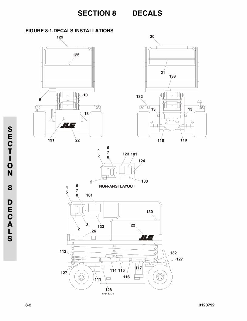
SECTION 8 DECALS
SECTION
8
DECALS
FIGURE 8-1.DECALS INSTALLATIONS
125
129
910
22131
20
21133
132
13 1313
118 119
101
678
678
45
45
124
123
133
101
NON-ANSI LAYOUT
2
2
3 13326
22
112
127
127
114
128
115
132
117
FAR SIDE
111
130
8-2 3120792
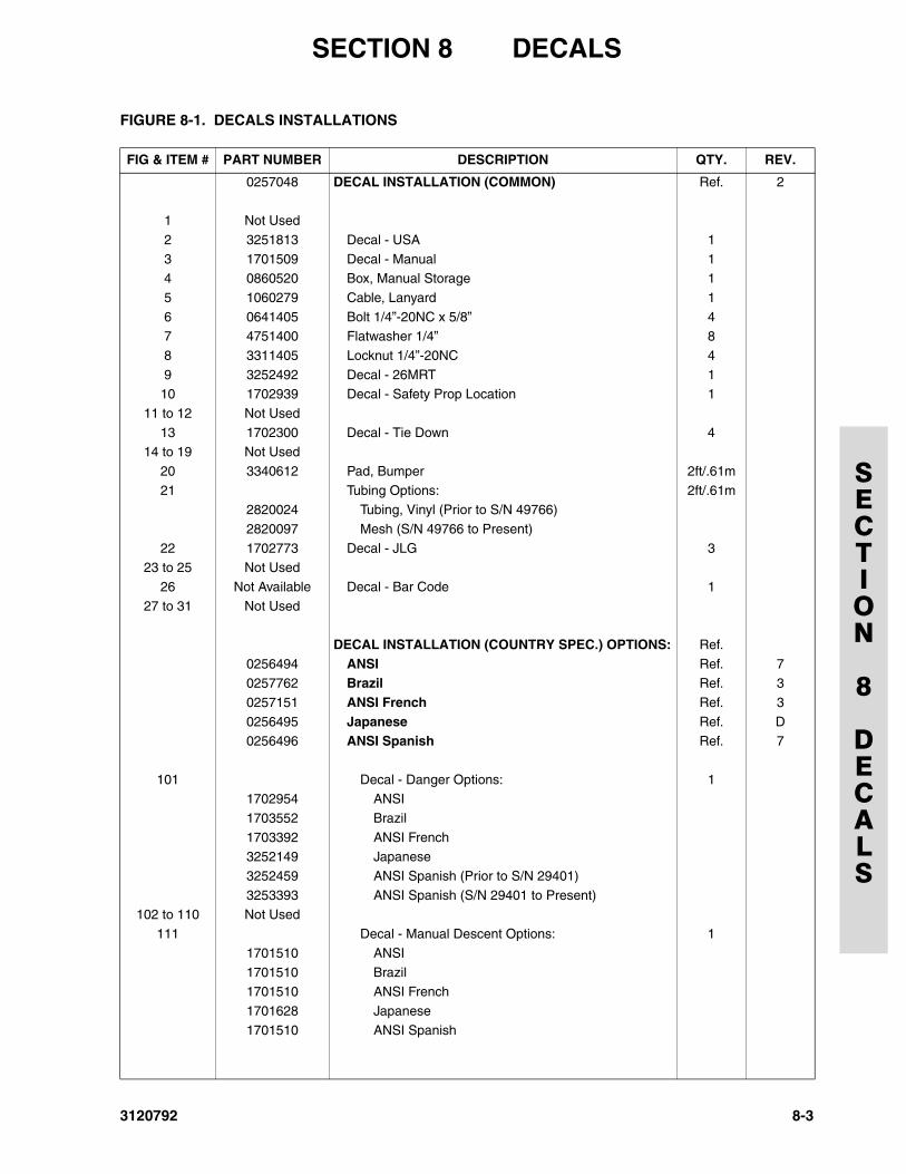
SECTION 8 DECALS
SECTION
8
DECALS
FIGURE 8-1. DECALS INSTALLATIONS
FIG & ITEM # PART NUMBER DESCRIPTION QTY. REV.
0257048 DECAL INSTALLATION (COMMON) Ref. 2
1 Not Used
2 3251813 Decal - USA 1
3 1701509 Decal - Manual 14 0860520 Box, Manual Storage 1
5 1060279 Cable, Lanyard 1
6 0641405 Bolt 1/4”-20NC x 5/8” 47 4751400 Flatwasher 1/4” 8
8 3311405 Locknut 1/4”-20NC 4
9 3252492 Decal - 26MRT 110 1702939 Decal - Safety Prop Location 1
11 to 12 Not Used
13 1702300 Decal - Tie Down 414 to 19 Not Used
20 3340612 Pad, Bumper 2ft/.61m
21 Tubing Options: 2ft/.61m2820024 Tubing, Vinyl (Prior to S/N 49766)
2820097 Mesh (S/N 49766 to Present)
22 1702773 Decal - JLG 323 to 25 Not Used
26 Not Available Decal - Bar Code 1
27 to 31 Not Used
DECAL INSTALLATION (COUNTRY SPEC.) OPTIONS: Ref.
0256494 ANSI Ref. 70257762 Brazil Ref. 3
0257151 ANSI French Ref. 3
0256495 Japanese Ref. D0256496 ANSI Spanish Ref. 7
101 Decal - Danger Options: 11702954 ANSI
1703552 Brazil
1703392 ANSI French3252149 Japanese
3252459 ANSI Spanish (Prior to S/N 29401)
3253393 ANSI Spanish (S/N 29401 to Present)102 to 110 Not Used
111 Decal - Manual Descent Options: 1
1701510 ANSI
1701510 Brazil1701510 ANSI French
1701628 Japanese
1701510 ANSI Spanish
3120792 8-3
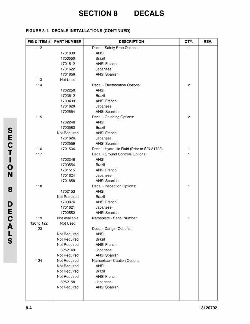
SECTION 8 DECALS
SECTION
8
DECALS
8-4 3120792
112 Decal - Safety Prop Options: 11701839 ANSI
1703550 Brazil
1701512 ANSI French
1701622 Japanese1701856 ANSI Spanish
113 Not Used
114 Decal - Electrocution Options: 21702250 ANSI
1703612 Brazil
1703499 ANSI French1701620 Japanese
1702554 ANSI Spanish
115 Decal - Crushing Options: 21702246 ANSI
1703583 Brazil
Not Required ANSI French1701626 Japanese
1702559 ANSI Spanish
116 1701504 Decal - Hydraulic Fluid (Prior to S/N 31728) 1117 Decal - Ground Controls Options: 1
1702248 ANSI
1703554 Brazil1701515 ANSI French
1701624 Japanese
1701858 ANSI Spanish118 Decal - Inspection Options: 1
1702153 ANSI
Not Required Brazil1703074 ANSI French
1701621 Japanese
1702552 ANSI Spanish119 Not Available Nameplate - Serial Number 1
120 to 122 Not Used
123 Decal - Danger Options:Not Required ANSI
Not Required Brazil
Not Required ANSI French3252149 Japanese
Not Required ANSI Spanish
124 Not Required Nameplate - Caution Options:
Not Required ANSINot Required Brazil
Not Required ANSI French
3252158 JapaneseNot Required ANSI Spanish
FIGURE 8-1. DECALS INSTALLATIONS (CONTINUED)
FIG & ITEM # PART NUMBER DESCRIPTION QTY. REV.
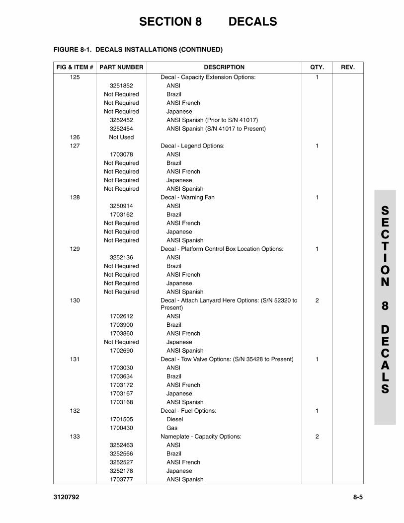
SECTION 8 DECALS
SECTION
8
DECALS
125 Decal - Capacity Extension Options: 13251852 ANSI
Not Required Brazil
Not Required ANSI French
Not Required Japanese3252452 ANSI Spanish (Prior to S/N 41017)
3252454 ANSI Spanish (S/N 41017 to Present)
126 Not Used127 Decal - Legend Options: 1
1703078 ANSI
Not Required BrazilNot Required ANSI French
Not Required Japanese
Not Required ANSI Spanish128 Decal - Warning Fan 1
3250914 ANSI
1703162 BrazilNot Required ANSI French
Not Required Japanese
Not Required ANSI Spanish129 Decal - Platform Control Box Location Options: 1
3252136 ANSI
Not Required BrazilNot Required ANSI French
Not Required Japanese
Not Required ANSI Spanish130 Decal - Attach Lanyard Here Options: (S/N 52320 to
Present)2
1702612 ANSI
1703900 Brazil
1703860 ANSI French Not Required Japanese
1702690 ANSI Spanish
131 Decal - Tow Valve Options: (S/N 35428 to Present) 11703030 ANSI
1703634 Brazil
1703172 ANSI French1703167 Japanese
1703168 ANSI Spanish
132 Decal - Fuel Options: 11701505 Diesel
1700430 Gas
133 Nameplate - Capacity Options: 2
3252463 ANSI3252566 Brazil
3252527 ANSI French
3252178 Japanese1703777 ANSI Spanish
FIGURE 8-1. DECALS INSTALLATIONS (CONTINUED)
FIG & ITEM # PART NUMBER DESCRIPTION QTY. REV.
3120792 8-5
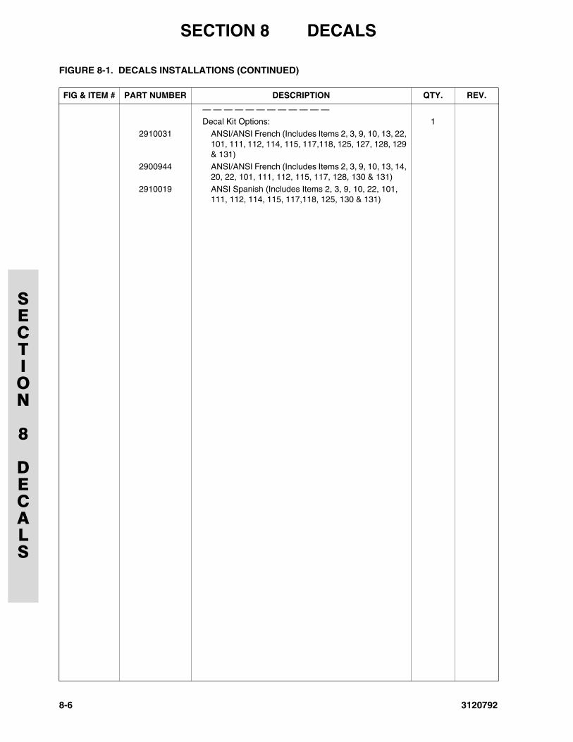
SECTION 8 DECALS
SECTION
8
DECALS
— — — — — — — — — — — — Decal Kit Options: 1
2910031 ANSI/ANSI French (Includes Items 2, 3, 9, 10, 13, 22, 101, 111, 112, 114, 115, 117,118, 125, 127, 128, 129 & 131)
2900944 ANSI/ANSI French (Includes Items 2, 3, 9, 10, 13, 14, 20, 22, 101, 111, 112, 115, 117, 128, 130 & 131)
2910019 ANSI Spanish (Includes Items 2, 3, 9, 10, 22, 101, 111, 112, 114, 115, 117,118, 125, 130 & 131)
FIGURE 8-1. DECALS INSTALLATIONS (CONTINUED)
FIG & ITEM # PART NUMBER DESCRIPTION QTY. REV.
8-6 3120792
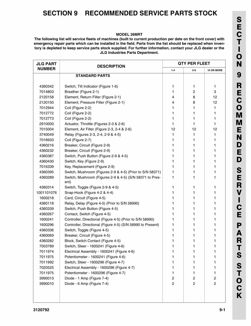
SECTION 9 RECOMMENDED SERVICE PARTS STOCK
SECTION9RECOMMENDEDSERVICEPARTSSTOCKMODEL 26MRTThe following list will service fleets of machines (built to current production per date on the front cover) with emergency repair parts which can be installed in the field. Parts from the list should be replaced when inven-tory is depleted to keep service parts stock supplied. For further information, contact your JLG dealer or the
JLG Industries Parts Department.
JLG PARTNUMBER
DESCRIPTIONQTY PER FLEET
1-4 5-9 10 OR MORE
STANDARD PARTS
4360342 Switch, Tilt Indicator (Figure 1-6) 1 1 1
7014803 Breather (Figure 2-1) 1 2 32120158 Element, Return Filter (Figure 2-1) 4 8 12
2120150 Element, Pressure Filter (Figure 2-1) 4 8 12
7012944 Coil (Figure 2-2) 1 1 17012772 Coil (Figure 2-2) 1 1 1
7012773 Coil (Figure 2-2) 1 1 1
2910000 Actuator, Throttle (Figures 2-3 & 2-6) 1 1 17015004 Element, Air Filter (Figure 2-3, 2-4 & 2-6) 12 12 12
3740049 Relay (Figures 2-3, 2-4, 2-9 & 4-5) 1 1 1
7018933 Coil (Figure 2-7) 1 1 14360216 Breaker, Circuit (Figure 2-9) 1 1 1
4360232 Breaker, Circuit (Figure 2-9) 1 1 1
4360387 Switch, Push Button (Figure 2-9 & 4-5) 1 1 14360430 Switch, Key (Figure 2-9) 1 1 1
7016339 Key, Replacement (Figure 2-9) 1 1 1
4360395 Switch, Mushroom (Figures 2-9 & 4-5) (Prior to S/N 58371) 1 1 14360289 Switch, Mushroom (Figures 2-9 & 4-5) (S/N 58371 to Pres-
ent)1 1 1
4360314 Switch, Toggle (Figure 2-9 & 4-5) 1 1 1
1001101076 Snap-Hook (Figure 4-2 & 4-4) 1 1 1
1600218 Card, Circuit (Figure 4-5) 1 1 14360118 Relay, Delay (Figure 4-5) (Prior to S/N 58990) 1 1 1
4360339 Switch, Push Button (Figure 4-5) 1 1 1
4360267 Contact, Switch (Figure 4-5) 1 1 11600241 Controller, Directional (Figure 4-5) (Prior to S/N 58990) 1 1 1
1600296 Controller, Directional (Figure 4-5) (S/N 58990 to Present) 1 1 1
4360336 Switch, Toggle (Figure 4-5) 1 1 14360069 Breaker, Circuit (Figure 4-5) 1 1 1
4360282 Block, Switch Contact (Figure 4-5) 1 1 1
7003789 Switch, Steer - 1600241 (Figure 4-6) 1 1 17011974 Electrical Assembly - 1600241 (Figure 4-6) 1 1 1
7011975 Potentiometer - 1600241 (Figure 4-6) 1 1 1
7011992 Switch, Steer - 1600296 (Figure 4-7) 1 1 1
7020525 Electrical Assembly - 1600296 (Figure 4-7) 1 1 17011975 Potentiometer - 1600296 (Figure 4-7) 1 1 1
3990013 Diode - 1 Amp (Figure 7-4) 2 2 2
3990010 Diode - 6 Amp (Figure 7-4) 2 2 2
3120792 9-1
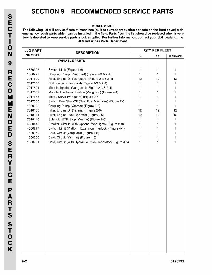
SECTION 9 RECOMMENDED SERVICE PARTS SECTION9RECOMMENDEDSERVICEPARTSSTOCK
VARIABLE PARTS
4360397 Switch, Limit (Figure 1-6) 1 1 1
1660229 Coupling Pump (Vanguard) (Figure 2-3 & 2-4) 1 1 17017600 Filter, Engine Oil (Vanguard) (Figure 2-3 & 2-4) 12 12 12
7017606 Coil, Ignition (Vanguard) (Figure 2-3 & 2-4) 1 1 1
7017621 Module, Ignition (Vanguard) (Figure 2-3 & 2-4) 1 1 17017659 Module, Electronic Ignition (Vanguard) (Figure 2-4) 1 1 1
7017655 Motor, Servo (Vanguard) (Figure 2-4) 1 1 1
7017500 Switch, Fuel Shut-Off (Dual Fuel Machines) (Figure 2-5) 1 1 11660228 Coupling Pump (Yanmar) (Figure 2-6) 1 1 1
7018103 Filter, Engine Oil (Yanmar) (Figure 2-6) 12 12 12
7018111 Filter, Engine Fuel (Yanmar) (Figure 2-6) 12 12 127018116 Solenoid, ETR Stop (Yanmar) (Figure 2-6) 1 1 1
4360448 Breaker, Circuit (With Optional Worklights) (Figure 2-9) 1 1 1
4360277 Switch, Limit (Platform Extension Interlock) (Figure 4-1) 1 1 11600249 Card, Circuit (Vanguard) (Figure 4-5) 1 1 1
1600250 Card, Circuit (Yanmar) (Figure 4-5) 1 1 1
1600291 Card, Circuit (With Hydraulic Drive Generator) (Figure 4-5) 1 1 1
MODEL 26MRTThe following list will service fleets of machines (built to current production per date on the front cover) with emergency repair parts which can be installed in the field. Parts from the list should be replaced when inven-tory is depleted to keep service parts stock supplied. For further information, contact your JLG dealer or the
JLG Industries Parts Department.
JLG PARTNUMBER
DESCRIPTIONQTY PER FLEET
1-4 5-9 10 OR MORE
9-2 3120792
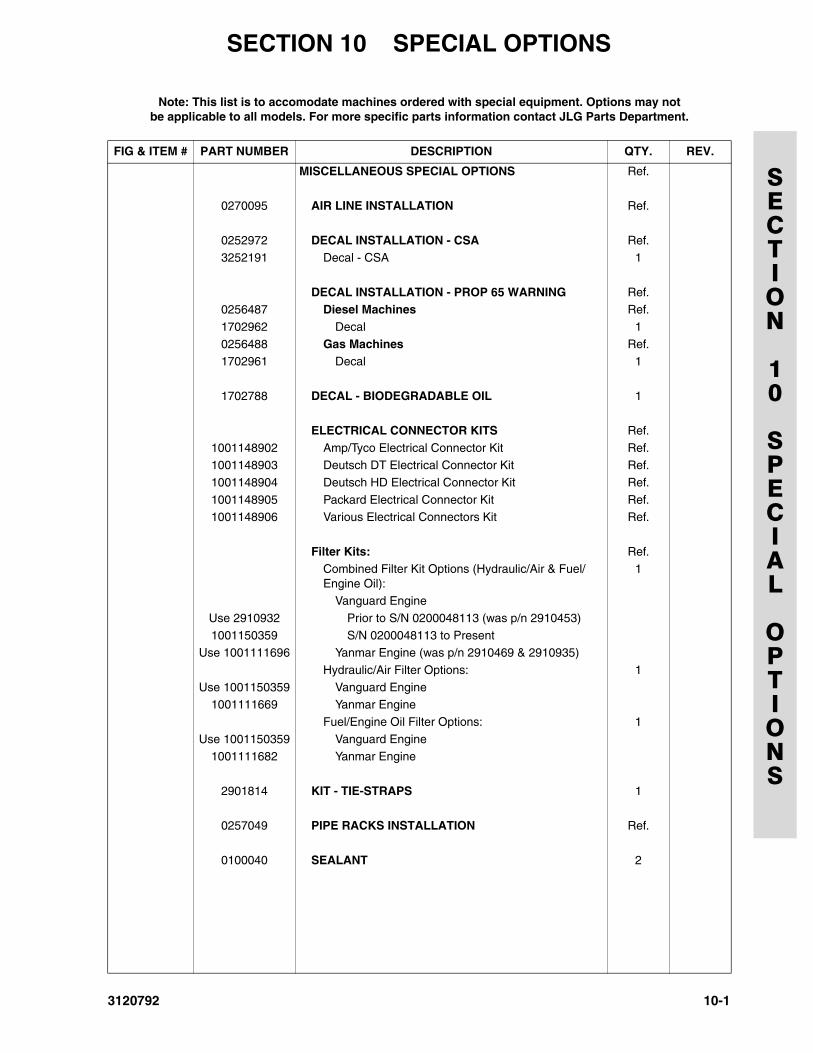
3120792
SECTION 10 SPECIAL OPTIONS
SECTION
10
SPECIAL
OPTIONS
Note: This list is to accomodate machines ordered with special equipment. Options may not be applicable to all models. For more specific parts information contact JLG Parts Department.
FIG & ITEM # PART NUMBER DESCRIPTION QTY. REV.
MISCELLANEOUS SPECIAL OPTIONS Ref.
0270095 AIR LINE INSTALLATION Ref.
0252972 DECAL INSTALLATION - CSA Ref.3252191 Decal - CSA 1
DECAL INSTALLATION - PROP 65 WARNING Ref.0256487 Diesel Machines Ref.
1702962 Decal 1
0256488 Gas Machines Ref.1702961 Decal 1
1702788 DECAL - BIODEGRADABLE OIL 1
ELECTRICAL CONNECTOR KITS Ref.
1001148902 Amp/Tyco Electrical Connector Kit Ref.1001148903 Deutsch DT Electrical Connector Kit Ref.
1001148904 Deutsch HD Electrical Connector Kit Ref.
1001148905 Packard Electrical Connector Kit Ref.1001148906 Various Electrical Connectors Kit Ref.
Filter Kits: Ref.Combined Filter Kit Options (Hydraulic/Air & Fuel/Engine Oil):
1
Vanguard Engine
Use 2910932 Prior to S/N 0200048113 (was p/n 2910453)
1001150359 S/N 0200048113 to PresentUse 1001111696 Yanmar Engine (was p/n 2910469 & 2910935)
Hydraulic/Air Filter Options: 1
Use 1001150359 Vanguard Engine1001111669 Yanmar Engine
Fuel/Engine Oil Filter Options: 1
Use 1001150359 Vanguard Engine1001111682 Yanmar Engine
2901814 KIT - TIE-STRAPS 1
0257049 PIPE RACKS INSTALLATION Ref.
0100040 SEALANT 2
10-1
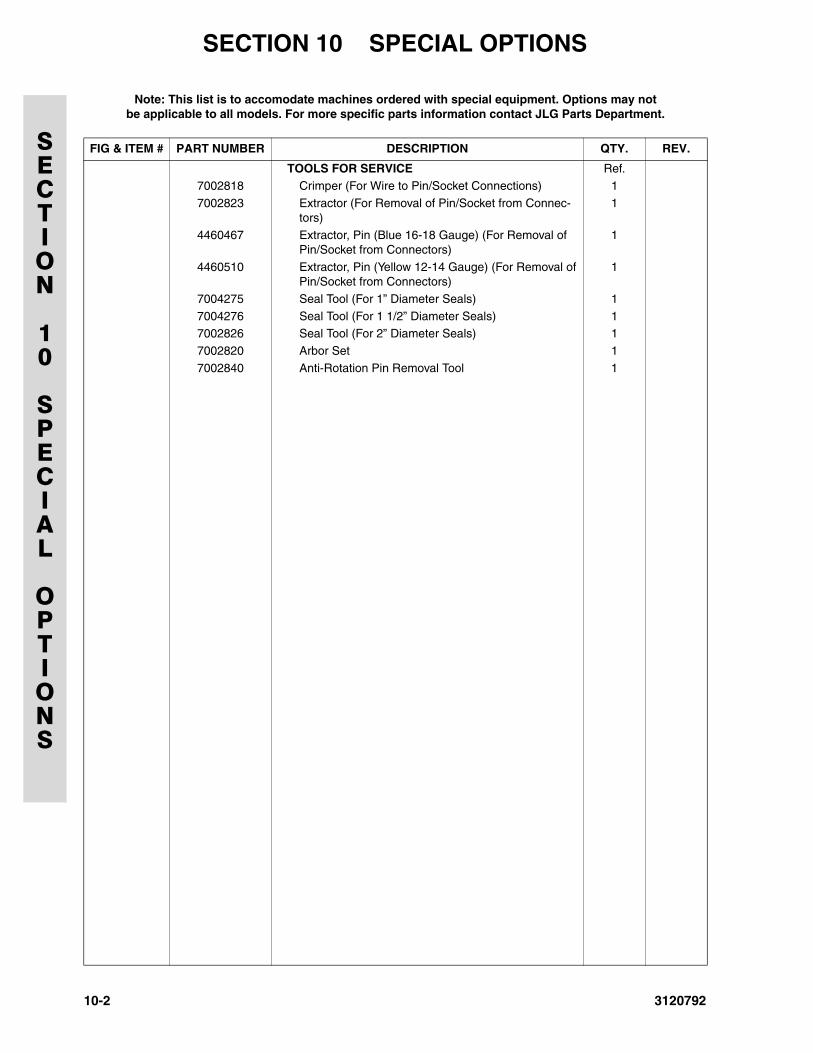
SECTION 10 SPECIAL OPTIONS
SECTION
10
SPECIAL
OPTIONS
TOOLS FOR SERVICE Ref.
7002818 Crimper (For Wire to Pin/Socket Connections) 1
7002823 Extractor (For Removal of Pin/Socket from Connec-tors)
1
4460467 Extractor, Pin (Blue 16-18 Gauge) (For Removal of Pin/Socket from Connectors)
1
4460510 Extractor, Pin (Yellow 12-14 Gauge) (For Removal of Pin/Socket from Connectors)
1
7004275 Seal Tool (For 1” Diameter Seals) 1
7004276 Seal Tool (For 1 1/2” Diameter Seals) 17002826 Seal Tool (For 2” Diameter Seals) 1
7002820 Arbor Set 1
7002840 Anti-Rotation Pin Removal Tool 1
Note: This list is to accomodate machines ordered with special equipment. Options may not be applicable to all models. For more specific parts information contact JLG Parts Department.
FIG & ITEM # PART NUMBER DESCRIPTION QTY. REV.
10-2 3120792

Corporate OfficeJLG Industries, Inc.
1 JLG DriveMcConnellsburg PA. 17233-9533
USA (717) 485-5161 (717) 485-6417
JLG Worldwide Locations
JLG Industries (Australia)P.O. Box 511911 Bolwarra RoadPort MacquarieN.S.W. 2444Australia
+61 2 65 811111
+61 2 65 813058
JLG Latino Americana Ltda.Rua Eng. Carlos Stevenson,80-Suite 7113092-310 Campinas-SPBrazil
+55 19 3295 0407
+55 19 3295 1025
JLG Industries (UK) LtdBentley HouseBentley AvenueMiddletonGreater ManchesterM24 2GP - England
+44 (0)161 654 1000
+44 (0)161 654 1001
JLG France SASZ.I. de Baulieu47400 FauilletFrance
+33 (0)5 53 88 31 70
+33 (0)5 53 88 31 79
JLG Deutschland GmbHMax-Planck-Str. 21D - 27721 Ritterhude - IhlpohlGermany
+49 (0)421 69 350 20
+49 (0)421 69 350 45
JLG Equipment Services Ltd.Rm 1107 Landmark North39 Lung Sum AvenueSheung Shui N. T.Hong Kong
(852) 2639 5783
(852) 2639 5797
JLG Industries (Italia) s.r.l.Via Po. 2220010 Pregnana Milanese - MIItaly
+39 029 359 5210
+39 029 359 5845
Oshkosh-JLG Singapore Technology Equipment Pte Ltd29 Tuas Ave 4,Jurong Industrial EstateSingapore, 639379
+65-6591 9030
+65-6591 9031
Plataformas Elevadoras JLG Iberica, S.L.Trapadella, 2P.I. Castellbisbal Sur08755 Castellbisbal, BarcelonaSpain
+34 93 772 4700
+34 93 771 1762
JLG Sverige ABEnkopingsvagen 150Box 704SE - 176 27 JarfallaSweden
+46 (0)850 659 500
+46 (0)850 659 534
www.jlg.com
3120792