Embed Size (px)
Citation preview
IllustratedOwner’s Manual
ROKON International Inc.50 Railroad AvenueRochester, NH 03839Tel: 603 335-3200Fax: 603 335-4400e-mail:[email protected] site: www.rokon.com
Made InThe USA
©2015 Rokon International, Inc. Printed in U.S.A. ROKON® and its logo are registered trademarks. Rev. 7
ROKON INTERNATIONAL, 50 Railroad Ave., Rochester, New Hampshire 03839, U.S.A. Copyright 2015
Welcome to the growing nation of ROKON owners. All operators must read and familiarizethemselves with this owner’s manual and all safety information.
The ROKON Warranty Statement is enclosed with this manual. For it to be validated, the complete ROKON Utility Vehicle Registration Card must be signed and returned to ROKON within 10 days of the date of purchase.
We congratulate you on your decision to purchase a ROKON Utility Vehicle. By following the procedures outlined in this manual, you will be rewarded with many hours of reliable, gratifying performance that others have come to expect from ROKON Utility Vehicles.
ROKON INTERNATIONAL, 50 Railroad Ave., Rochester, New Hampshire 03839, U.S.A. Copyright 2015
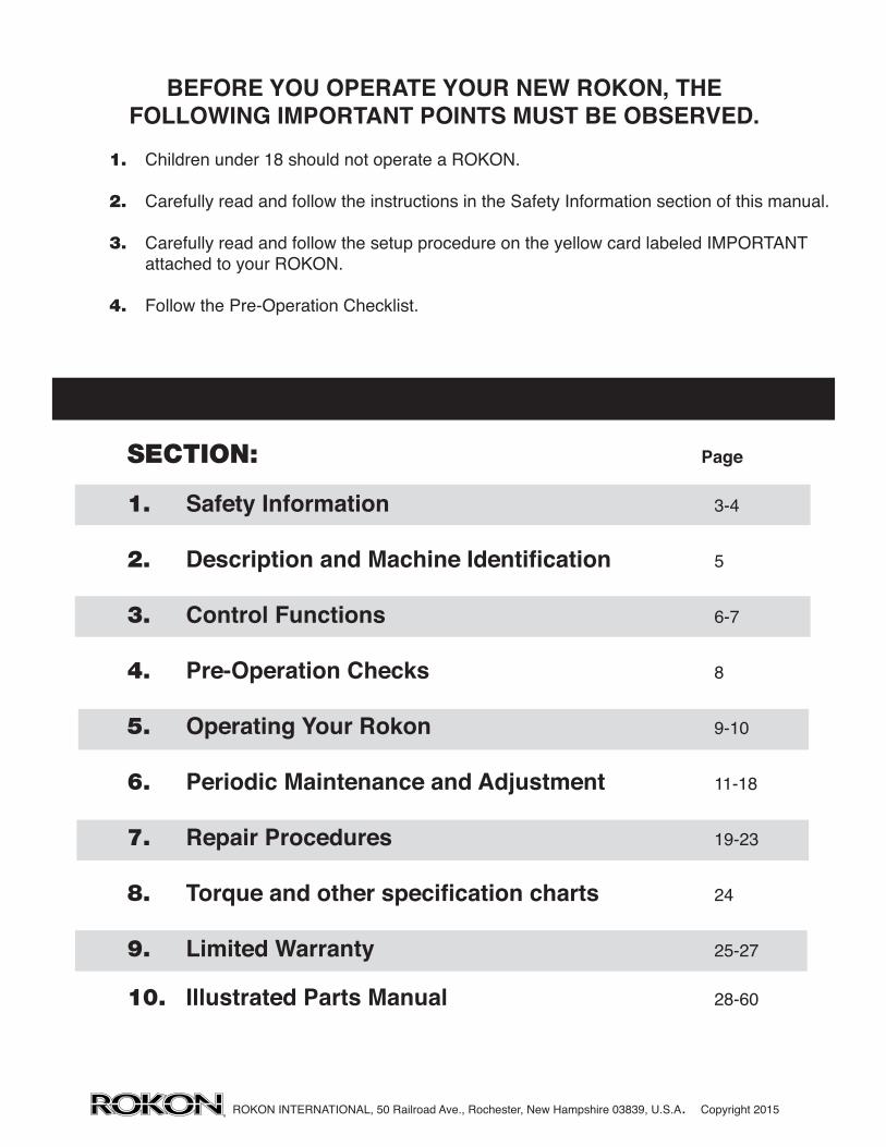
TABLE OF CONTENTS SECTION: Page
1. Safety Information 3-4
2. Description and Machine Identification 5
3. Control Functions 6-7
4. Pre-Operation Checks 8 5. Operating Your Rokon 9-10 6. Periodic Maintenance and Adjustment 11-18
7. Repair Procedures 19-23
8. Torque and other specification charts 24
9. Limited Warranty 25-27
10. Illustrated Parts Manual 28-60
BEFORE YOU OPERATE YOUR NEW ROKON, THE FOLLOWING IMPORTANT POINTS MUST BE OBSERVED.
1. Children under 18 should not operate a ROKON.
2. Carefully read and follow the instructions in the Safety Information section of this manual.
3. Carefully read and follow the setup procedure on the yellow card labeled IMPORTANT attached to your ROKON.
4. Follow the Pre-Operation Checklist.
ROKON INTERNATIONAL, 50 Railroad Ave., Rochester, New Hampshire 03839, U.S.A. Copyright 2015 3
Always wear an approved motorcycle helmet that fits properly, eye protection (goggles or face shield), gloves, sturdy boots, long sleeve shirt, jacket and pants while operating a ROKON.
Never consume alcohol or drugs before or while operating a ROKON.
The ROKON is a go slow vehicle. Never operate at speeds too fast for your skills or the conditions. Always operate at a speed that is appropriate for the terrain, visibility and operating conditions and your experience.
DANGER-SERIOUS INJURY MAY RESULT! Never attempt wheelies, jumps or other stunts of any kind while operating a ROKON.
Always keep both hands on the handlebars during operation.
Always go slow and be extra careful when operating on unfamiliar terrain. Always be alert to changing terrain conditions when operating a ROKON.
Never operate on excessively rough, slippery or loose terrain until you have learned and practiced the skills necessary to control a ROKON on such terrain.
Never operate on hills too steep for a ROKON or for your abilities. Never exceed a 60% grade (or 31 degrees). Practice on smaller hills before attempting larger hills.Shift down early to ride in control and prevent slipping the torque converter belt.
Always follow proper procedures for climbing hills as described in this manual. Check the terrain carefully before you start up any hill. Never climb hills with excessively slippery or loose surfaces. Shift your weight forward when on an incline.
Always follow proper procedures for going down hills and for braking on hills as de-scribed in this manual on pages 9 and 10. Check the terrain carefully before you start down any hill. Shift your weight rearward. Never go down a hill at high speed. Shift into 1st range and keep the torque converter engaged for engine braking as described on page 9 in this manual. Use the rear brake only in down hill corners. Apply the rear brake before the front brake when going straight down.
Always maintain proper tire pressure of 5 PSI.
Never modify your ROKON. Use only ROKON parts. Follow instructions, and properlyinstall ROKON parts.
Section 1 Safety Information
ROKON INTERNATIONAL, 50 Railroad Ave., Rochester, New Hampshire 03839, U.S.A. Copyright 20154
Never exceed the stated load capacity of 600 lbs. Cargo should be properly distributed and securely attached. Reduce speed and follow instructions in this manual for carrying cargo or pulling a trailer. Be careful to allow greater distances for braking when carrying cargo or operating with a trailer.
Read your engine manual completely and follow all safety instructions.
WARNING: Potential Hazard- Improper Handling of Gasoline can catch fire and you could be burned.
Always turn off the engine when refueling. Do not refuel right after the engine has been running and is still very hot. Do not spill gasoline on the engine or exhaust pipe/muffler when refueling. Never refuel while smoking, or while in the vicinity of sparks, open flames or other sources of ignition such as the pilot lights of water heaters and clothes dryers. When transporting the machine in another vehicle be sure that it is kept upright and that the Fuel Tank Shut-Off Valve and Engine Fuel Valve are in the “OFF” position (see page 6 of manual). Otherwise, fuel may leak out of the carburetor and flood the engine.
Gasoline is poisonous and can cause injuries. If you swallow gasoline, inhale an excessive amount of gasoline vapor, or get gasoline in your eyes, seek medical attention immediately. If gasoline spills on your skin, wash with soap and water. If gasoline spills on your clothes, change your clothes.
WARNING Potential Hazard- Starting or running the engine in a closed area.
Exhaust fumes are poisonous and may cause loss of consciousness and death within a short time. Always operate your machine in an area with adequate ventilation. Do not operate indoors.
Section 1 Safety Information
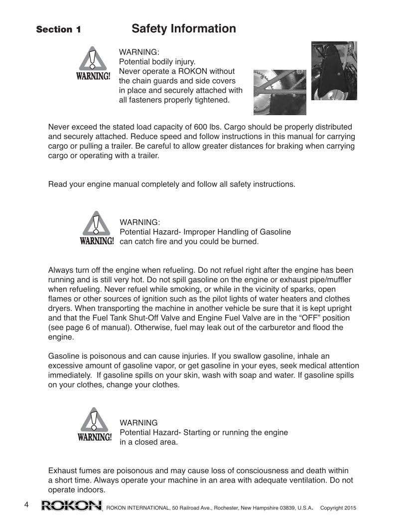
WARNING:Potential bodily injury. Never operate a ROKON without the chain guards and side covers in place and securely attached withall fasteners properly tightened.
ROKON INTERNATIONAL, 50 Railroad Ave., Rochester, New Hampshire 03839, U.S.A. Copyright 2015 5
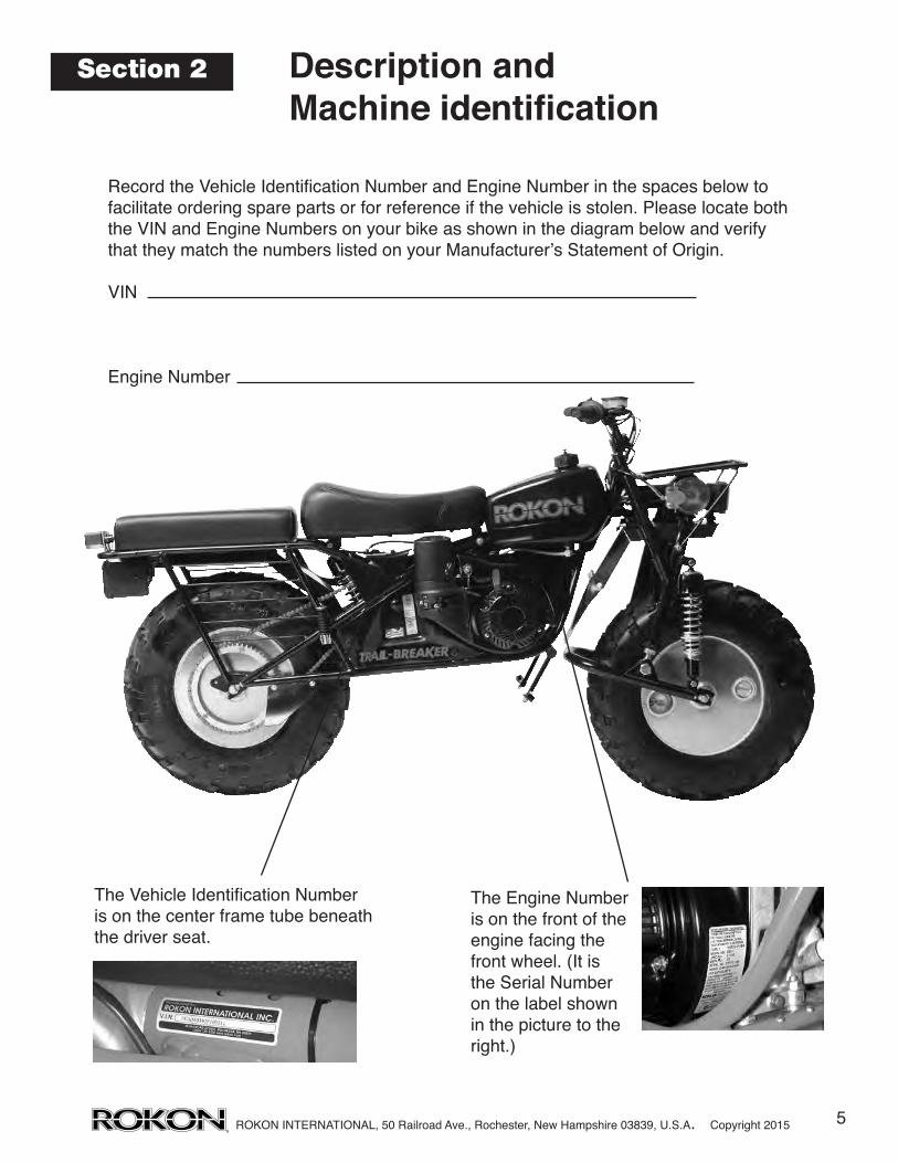
Record the Vehicle Identification Number and Engine Number in the spaces below to facilitate ordering spare parts or for reference if the vehicle is stolen. Please locate both the VIN and Engine Numbers on your bike as shown in the diagram below and verify that they match the numbers listed on your Manufacturer’s Statement of Origin.
VIN
Engine Number
Section 2 Description and Machine identification
The Engine Numberis on the front of the engine facing the front wheel. (It is the Serial Number on the label shown in the picture to the right.)
The Vehicle Identification Number is on the center frame tube beneath the driver seat.
ROKON INTERNATIONAL, 50 Railroad Ave., Rochester, New Hampshire 03839, U.S.A. Copyright 20156
REAR
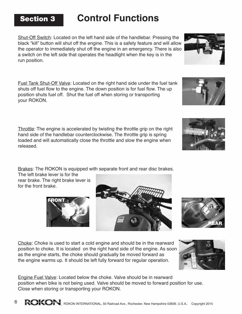
Shut-Off Switch: Located on the left hand side of the handlebar. Pressing theblack “kill” button will shut off the engine. This is a safety feature and will allowthe operator to immediately shut off the engine in an emergency. There is alsoa switch on the left side that operates the headlight when the key is in therun position.
Fuel Tank Shut-Off Valve: Located on the right hand side under the fuel tankshuts off fuel flow to the engine. The down position is for fuel flow. The upposition shuts fuel off. Shut the fuel off when storing or transportingyour ROKON.
Throttle: The engine is accelerated by twisting the throttle grip on the right hand side of the handlebar counterclockwise. The throttle grip is spring loaded and will automatically close the throttle and slow the engine when released.
Brakes: The ROKON is equipped with separate front and rear disc brakes. The left brake lever is for the rear brake. The right brake lever is for the front brake.
Choke: Choke is used to start a cold engine and should be in the rearward position to choke. It is located on the right hand side of the engine. As soon as the engine starts, the choke should gradually be moved forward as the engine warms up. It should be left fully forward for regular operation.
Engine Fuel Valve: Located below the choke. Valve should be in rearwardposition when bike is not being used. Valve should be moved to forward position for use. Close when storing or transporting your ROKON.
FRONT
Section 3 Control Functions
ROKON INTERNATIONAL, 50 Railroad Ave., Rochester, New Hampshire 03839, U.S.A. Copyright 2015 7
Section 3 Control Functions
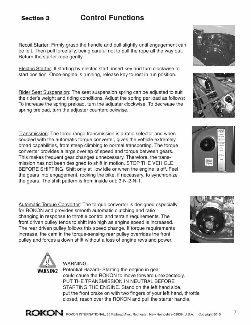
Recoil Starter: Firmly grasp the handle and pull slightly until engagement can be felt. Then pull forcefully, being careful not to pull the rope all the way out. Return the starter rope gently.
Electric Starter: If starting by electric start, insert key and turn clockwise tostart position. Once engine is running, release key to rest in run position.
Rider Seat Suspension: The seat suspension spring can be adjusted to suit the rider’s weight and riding conditions. Adjust the spring per load as follows: To increase the spring preload, turn the adjuster clockwise. To decrease the spring preload, turn the adjuster counterclockwise.
Transmission: The three range transmission is a ratio selector and when coupled with the automatic torque converter, gives the vehicle extremelybroad capabilities, from steep climbing to normal transporting. The torque converter provides a large overlap of speed and torque between gears. This makes frequent gear changes unnecessary. Therefore, the trans-mission has not been designed to shift in motion. STOP THE VEHICLE BEFORE SHIFTING. Shift only at low idle or when the engine is off. Feel the gears into engagement, rocking the bike, if necessary, to synchronize the gears. The shift pattern is from inside out: 3-N-2-N-1.
Automatic Torque Converter: The torque converter is designed especially for ROKON and provides smooth automatic clutching and ratio changing in response to throttle control and terrain requirements. Thefront driven pulley tends to shift into high as engine speed is increased. The rear driven pulley follows this speed change. If torque requirementsincrease, the cam in the torque-sensing rear pulley overrides the front pulley and forces a down shift without a loss of engine revs and power.
WARNING: Potential Hazard- Starting the engine in gear could cause the ROKON to move forward unexpectedly. PUT THE TRANSMISSION IN NEUTRAL BEFORE STARTING THE ENGINE. Stand on the left hand side, put the front brake on with two fingers of your left hand, throttle closed, reach over the ROKON and pull the starter handle.
ROKON INTERNATIONAL, 50 Railroad Ave., Rochester, New Hampshire 03839, U.S.A. Copyright 20158
Section 4 Pre-operation Checks
Before using this machine, check the following points.
Front and Rear Brake: Check brake action. Check pucks to see that they are not over worn. There should be visible brake material on both sides of the brake disc. See Section 6.
Fuel Tank: Check fuel level. Fill as necessary.
Engine Oil: The engine holds .6 qt. of SAE10W30/40 motor oil. Fill to the dipstick “full” line.
Miter Box and Transmission: Both are filled at the factory and need not be checked at the start. The miter box should have 2.5 oz. of EP 80W-90 gear lube oil. Thetransmission takes 6 oz. of EP 80W-90 gear lube oil. The transmission has a fill to plug near the bottom of the transmission (shown on page 51). There is no fill level for the miter box so measure before filling. Over filling of either the miter box or transmission will result in leakage.
Throttle: Check for proper throttle cable operation. Look for smooth response to twist action.
Wheels and Tires: Check Tire pressure, inspect for wear and damage.
Fittings and Fasteners: Check all fittings and fasteners.
Drive Chains: Check chains for tension and lubrication. Adjust tension for 1/2” - 3/4” deflection at mid point.
Engine Manual: Read your engine manual completely and follow all instructions.
FAILURE TO INSPECT YOUR ROKON BEFORE OPERATION INCREASES THE POSSIBILITY OF AN ACCIDENT OR EQUIPMENT
DAMAGE. ALWAYS INSPECT YOUR ROKON EACH TIME YOU USE IT TO MAKE SURE IT IS IN SAFE OPERATING CONDITION.
ROKON INTERNATIONAL, 50 Railroad Ave., Rochester, New Hampshire 03839, U.S.A. Copyright 2015 9
Section 5 Operating Your ROKON
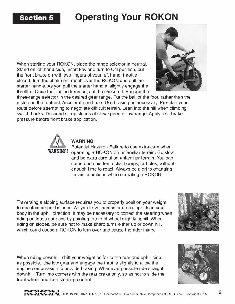
When starting your ROKON, place the range selector in neutral. Stand on left hand side, insert key and turn to ON position, put the front brake on with two fingers of your left hand, throttleclosed, turn the choke on, reach over the ROKON and pull thestarter handle. As you pull the starter handle, slightly engage thethrottle. Once the engine turns on, set the choke off. Engage thethree-range selector in the desired gear range. Put the ball of the foot, rather than the instep on the footrest. Accelerate and ride. Use braking as necessary. Pre-plan your route before attempting to negotiate difficult terrain. Lean into the hill when climbing switch backs. Descend steep slopes at slow speed in low range. Apply rear brake pressure before front brake application.
WARNING Potential Hazard - Failure to use extra care when operating a ROKON on unfamiliar terrain. Go slow and be extra careful on unfamiliar terrain. You can come upon hidden rocks, bumps, or holes, without enough time to react. Always be alert to changing terrain conditions when operating a ROKON.
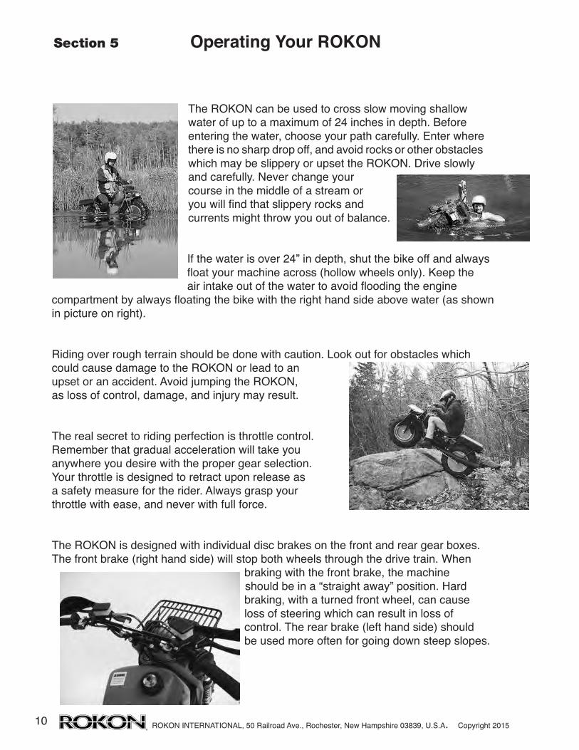
Traversing a sloping surface requires you to properly position your weight to maintain proper balance. As you travel across or up a slope, lean your body in the uphill direction. It may be necessary to correct the steering whenriding on loose surfaces by pointing the front wheel slightly uphill. When riding on slopes, be sure not to make sharp turns either up or down hill,which could cause a ROKON to turn over and cause the rider injury.
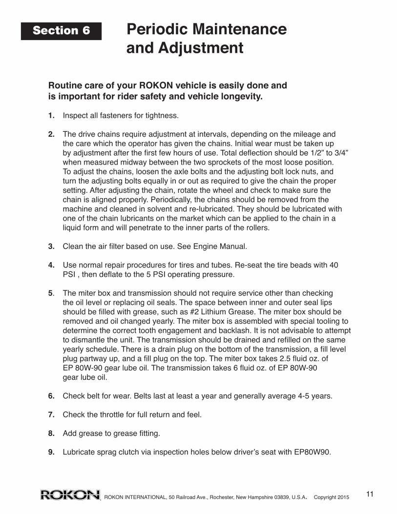
When riding downhill, shift your weight as far to the rear and uphill side as possible. Use low gear and engage the throttle slightly to allow the engine compression to provide braking. Whenever possible ride straight downhill. Turn into corners with the rear brake only, so as not to slide thefront wheel and lose steering control.
ROKON INTERNATIONAL, 50 Railroad Ave., Rochester, New Hampshire 03839, U.S.A. Copyright 201510
Section 5 Operating Your ROKON
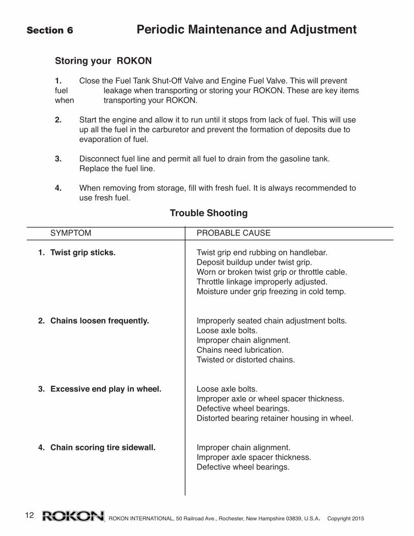
The ROKON can be used to cross slow moving shallow water of up to a maximum of 24 inches in depth. Before entering the water, choose your path carefully. Enter where there is no sharp drop off, and avoid rocks or other obstacles which may be slippery or upset the ROKON. Drive slowly and carefully. Never change your course in the middle of a stream or you will find that slippery rocks and currents might throw you out of balance.
If the water is over 24” in depth, shut the bike off and always float your machine across (hollow wheels only). Keep the air intake out of the water to avoid flooding the engine
compartment by always floating the bike with the right hand side above water (as shown in picture on right).
Riding over rough terrain should be done with caution. Look out for obstacles which could cause damage to the ROKON or lead to an upset or an accident. Avoid jumping the ROKON, as loss of control, damage, and injury may result.
The real secret to riding perfection is throttle control. Remember that gradual acceleration will take youanywhere you desire with the proper gear selection. Your throttle is designed to retract upon release as a safety measure for the rider. Always grasp yourthrottle with ease, and never with full force.
The ROKON is designed with individual disc brakes on the front and rear gear boxes. The front brake (right hand side) will stop both wheels through the drive train. When braking with the front brake, the machine should be in a “straight away” position. Hard braking, with a turned front wheel, can cause loss of steering which can result in loss of control. The rear brake (left hand side) should be used more often for going down steep slopes.
ROKON INTERNATIONAL, 50 Railroad Ave., Rochester, New Hampshire 03839, U.S.A. Copyright 2015 11
Routine care of your ROKON vehicle is easily done and is important for rider safety and vehicle longevity.
1. Inspect all fasteners for tightness.
2. The drive chains require adjustment at intervals, depending on the mileage and the care which the operator has given the chains. Initial wear must be taken up by adjustment after the first few hours of use. Total deflection should be 1/2” to 3/4” when measured midway between the two sprockets of the most loose position. To adjust the chains, loosen the axle bolts and the adjusting bolt lock nuts, and turn the adjusting bolts equally in or out as required to give the chain the proper setting. After adjusting the chain, rotate the wheel and check to make sure the chain is aligned properly. Periodically, the chains should be removed from the machine and cleaned in solvent and re-lubricated. They should be lubricated with one of the chain lubricants on the market which can be applied to the chain in a liquid form and will penetrate to the inner parts of the rollers.
3. Clean the air filter based on use. See Engine Manual.
4. Use normal repair procedures for tires and tubes. Re-seat the tire beads with 40 PSI , then deflate to the 5 PSI operating pressure.
5. The miter box and transmission should not require service other than checking the oil level or replacing oil seals. The space between inner and outer seal lips should be filled with grease, such as #2 Lithium Grease. The miter box should be removed and oil changed yearly. The miter box is assembled with special tooling to determine the correct tooth engagement and backlash. It is not advisable to attempt to dismantle the unit. The transmission should be drained and refilled on the same yearly schedule. There is a drain plug on the bottom of the transmission, a fill level plug partway up, and a fill plug on the top. The miter box takes 2.5 fluid oz. of EP 80W-90 gear lube oil. The transmission takes 6 fluid oz. of EP 80W-90 gear lube oil.
6. Check belt for wear. Belts last at least a year and generally average 4-5 years.
7. Check the throttle for full return and feel.
8. Add grease to grease fitting.
9. Lubricate sprag clutch via inspection holes below driver’s seat with EP80W90.
Section 6 Periodic Maintenance and Adjustment
ROKON INTERNATIONAL, 50 Railroad Ave., Rochester, New Hampshire 03839, U.S.A. Copyright 201512
Trouble Shooting
SYMPTOM PROBABLE CAUSE
1. Twist grip sticks. Twist grip end rubbing on handlebar. Deposit buildup under twist grip. Worn or broken twist grip or throttle cable. Throttle linkage improperly adjusted. Moisture under grip freezing in cold temp.
2. Chains loosen frequently. Improperly seated chain adjustment bolts. Loose axle bolts. Improper chain alignment. Chains need lubrication. Twisted or distorted chains.
3. Excessive end play in wheel. Loose axle bolts. Improper axle or wheel spacer thickness. Defective wheel bearings. Distorted bearing retainer housing in wheel.
4. Chain scoring tire sidewall. Improper chain alignment. Improper axle spacer thickness. Defective wheel bearings.
Section 6 Periodic Maintenance and Adjustment
Storing your ROKON
1. Close the Fuel Tank Shut-Off Valve and Engine Fuel Valve. This will prevent fuel leakage when transporting or storing your ROKON. These are key items when transporting your ROKON.
2. Start the engine and allow it to run until it stops from lack of fuel. This will use up all the fuel in the carburetor and prevent the formation of deposits due to evaporation of fuel.
3. Disconnect fuel line and permit all fuel to drain from the gasoline tank. Replace the fuel line.
4. When removing from storage, fill with fresh fuel. It is always recommended to use fresh fuel.
ROKON INTERNATIONAL, 50 Railroad Ave., Rochester, New Hampshire 03839, U.S.A. Copyright 2015 13
Section 6 Periodic Maintenance and Adjustment
Trouble Shooting
SYMPTOM PROBABLE CAUSE
5. Noisy driveline. Driveline improperly seated. Worn or broken overrunning clutch spring. Worn, broken or loose carrier bearing or bearing retainer. Worn bosses leading into overrunning clutch spring. Worn universal joint.
6. Noisy front miter box. Low oil level. Loose gearbox mounting bolts. Worn or broken bevel gears. Worn shaft bearings. Improper gear mesh.
7. Rear wheel won’t drive. Wheel chain off sprocket. Sheared roll pin on drive sprocket. 8. Front wheel won’t drive. Wheel chain off sprockets. Sheared roll pin in sprocket. Broken overrunning clutch spring on driveline. Worn bosses leading to overrunning clutch spring. Defective transmission.
9. Engine stalls when Debris in carburetor. machine stops. Improperly adjusted throttle linkage. Ice in system. Idle set too low.
10. Valve core disappears Tire pressure too low. within wheel. (only tubed tires) Tube not secured by stem kit.
ROKON INTERNATIONAL, 50 Railroad Ave., Rochester, New Hampshire 03839, U.S.A. Copyright 201514
Section 6 Periodic Maintenance and Adjustment
Trouble Shooting Engine
SYMPTOM PROBABLE CAUSE
1. Engine will not start. No fuel in tank or Fuel Tank Shut-Off Valve closed. Spark plug not firing. Fuel not being delivered to combustion chamber. Engine flooded. Too much fuel in combustion chamber. Improper spark plug gap. Plugged fuel filter.
2. Engine hard to start. Water or dirt in fuel or stale fuel mixture. Weak ignition spark. Plugged air filter. Engine over or under choked. Gasket or seal leaks. Spark plug fouled.
3. Engine starts but will Insufficient fuel supply. not continue to run. Fuel line clogged. Vent on filler cap plugged. Dirty carburetor. Air leak in fuel system. Defective or fouled spark plug. Idle screw not adjusted properly.
4. Engine misses. Dirt in fuel system. Spark plug fouled or defective. Faulty magneto or improper ignition coil air gap setting. Idle screw not adjusted properly.
5. Engine lacks power. Air cleaner clogged. Incorrect spark plug – gap too wide or too narrow. Incorrect air gap on ignition coil. Worn or stuck piston rings or leaky head gasket. Ice in system. Hi altitude running. (use hi altitude jet)
ROKON INTERNATIONAL, 50 Railroad Ave., Rochester, New Hampshire 03839, U.S.A. Copyright 2015 15
Section 6 Periodic Maintenance and Adjustment
Trouble Shooting Engine
SYMPTOM PROBABLE CAUSE
6. Engine overheats. Engine overloaded. Oil too low in crankcase. Incorrect spark plug. Ignition timing over-advanced. Scored piston or cylinder wall. Lean Mixture. Dirty air filter / blocked air intake. Dirty cylinder cooling fins.
7. Engine noisy or knocking. Loose flywheel. Worn bearings. Broken or loose parts inside engine. Lack of oil in crankcase.
8. Engine stalls under load. Fuel line restricted or tank vent closed. Engine overloaded.
9. Poor acceleration. Air cleaner clogged. Ignition timing over-advanced or retarded. Leaking gaskets. Air gap too wide. Exhaust restriction. Low compression.
10. Poor high speed performance. Low compression. Pre-ignition. Improper spark plug or air gap. Belt worn. Brakes dragging.
ROKON INTERNATIONAL, 50 Railroad Ave., Rochester, New Hampshire 03839, U.S.A. Copyright 201516
Care and Adjustment of ROKON Brakes
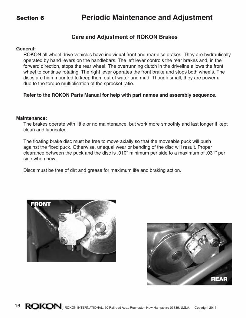
General: ROKON all wheel drive vehicles have individual front and rear disc brakes. They are hydraulically operated by hand levers on the handlebars. The left lever controls the rear brakes and, in the forward direction, stops the rear wheel. The overrunning clutch in the driveline allows the front wheel to continue rotating. The right lever operates the front brake and stops both wheels. The discs are high mounted to keep them out of water and mud. Though small, they are powerful due to the torque multiplication of the sprocket ratio.
Refer to the ROKON Parts Manual for help with part names and assembly sequence.
Maintenance: The brakes operate with little or no maintenance, but work more smoothly and last longer if kept clean and lubricated.
The floating brake disc must be free to move axially so that the moveable puck will push against the fixed puck. Otherwise, unequal wear or bending of the disc will result. Proper clearance between the puck and the disc is .010” minimum per side to a maximum of .031” per side when new.
Discs must be free of dirt and grease for maximum life and braking action.
REAR
FRONT
Section 6 Periodic Maintenance and Adjustment
ROKON INTERNATIONAL, 50 Railroad Ave., Rochester, New Hampshire 03839, U.S.A. Copyright 2015 17
Section 6 Periodic Maintenance and AdjustmentMaintenance: Hydraulically operated brakes may be operated at pressures up to 1000 PSI using a petroleum hydraulic fluid compatible with Buna-N Seals. Use automotive DOT 3 or 4 Brake Fluid only. Do not pressure bleed with more than 5 PSI. If hydraulic brakes are not working properly, try “bleeding” them.
1. Orient handlebars to ensure brake reservoirs are level. Remove cover of malfunctioning brake reservoir and fill with hydraulic fluid to maximum line. (Throughout bleeding process, do not allow fluid to drop below minimum line.) Replace cover but leave loose to allow reservoir to vent during bleeding.
2. Find the corresponding brake caliper to the reservoir you have filled. Loosen upper bleeder screw on caliper.
3. Grasp brake lever and slowly engage brake to bleed. Air bubbles and hydraulic fluid will flow out of the loosened bleeder screw.
4. Before brake lever is fully seated, re-tighten bleeder screw on caliper. Allow brake lever to reset to resting position.
5. Refill brake reservoir as necessary.
6. Repeat steps 1-5 until bleeder screw is releasing a constant flow of hydraulic fluid with no air bubbles. 7. Tighten reservoir cover until it is sealed.
8. Repeat for other brake if also not working properly.
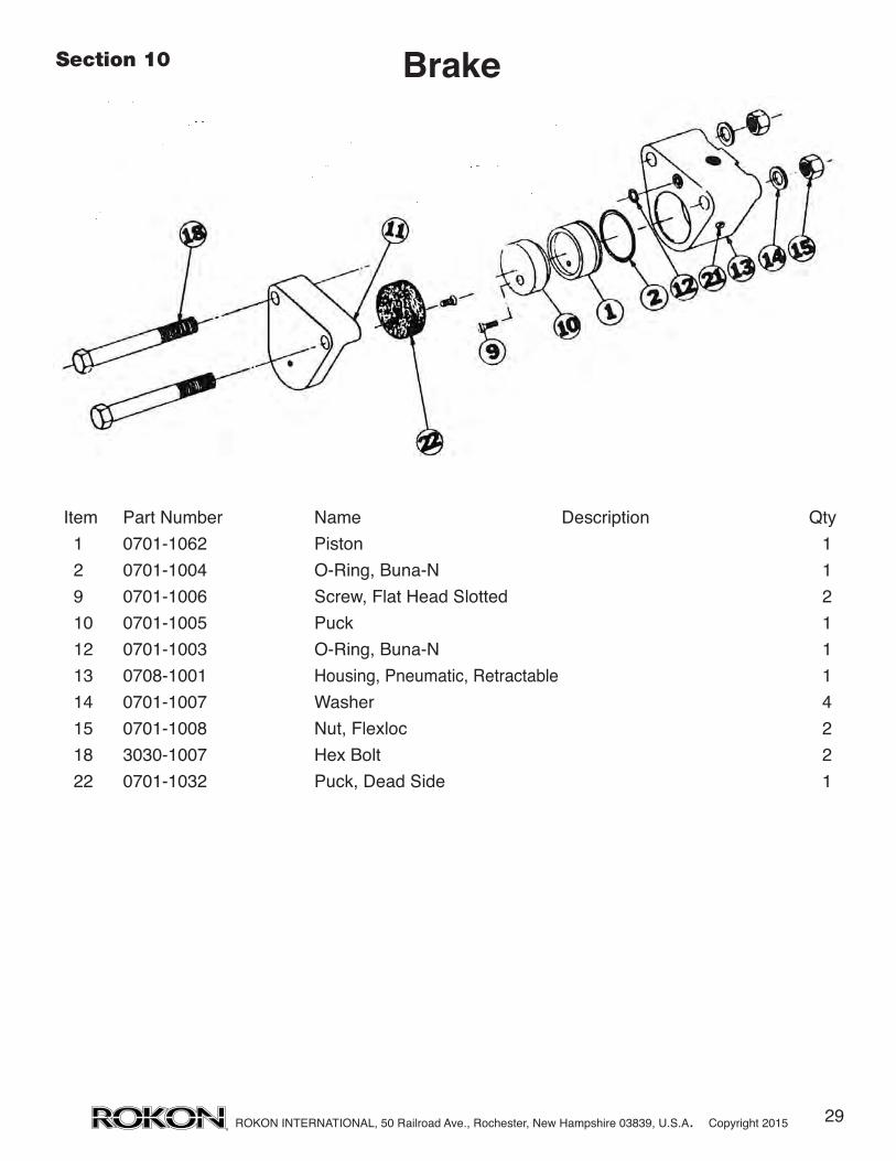
Maintenance Puck Replacement (See page 28 for diagram): 1. Be sure no pressure is applied to the caliper during puck replacement.
2. Hydraulic lines do not need to be removed.
3. Remove the two SAE grade 8 hex bolts (#18). This will dismount and disassemble the caliper, exposing the Pucks for replacement.
4. Remove the pan head screws (#9) that hold the Pucks (#10 & 22) in place on each side of the caliper. Remove Pucks from Housing (#13) and Dead Side Housing (#11).
5. Place new Pucks (#10 & 22) into Housings. Replace Pan Head Screws (#9), tighten to hold Pucks in place. (Note: Screw head will fit into recessed area of Puck. Be sure only friction material will contact disc when reassembled.)
6. Reassemble caliper and mount as before.
ROKON INTERNATIONAL, 50 Railroad Ave., Rochester, New Hampshire 03839, U.S.A. Copyright 201518
W
HICH
EVER
IN
ITIA
L IN
ITIA
L IN
ITIA
L EV
ERY
EVER
Y
COM
ES
MO
1
3 6
6 12
FIRS
T KM
32
0 13
00
2500
25
00
5000
(M
I) 20
0 80
0 16
00
1600
32
00
NO
ITEM
CH
ECK
OR
MAI
NTEN
ANCE
JO
B
HOUR
S 20
80
16
0 16
0 32
0 1
Air F
ilter E
lem
ent
Chec
k or
repl
ace
if ne
cess
ary
Ever
y 20
-40
hour
s, (m
ore
ofte
n in
wet
or d
usty
are
as)
2 To
rque
Con
verte
r, Fr
ont a
nd R
ear
Chec
k op
erat
ion
and
adju
st if
nec
essa
ry
X
X X
X 3
Fron
t and
Rea
r Bra
ke
Chec
k op
erat
ion
and
adju
st if
nec
essa
ry
X X
X X
X
Ch
eckfluidlevelandinspectforleaks
XX
XX
X
Re
plac
e Br
ake
Pads
when
ever
wor
n to
the
limit
4
Brak
e Ho
ses
Chec
k fo
r cra
cks
and
othe
r dam
age
X
X X
X
an
d re
pair
as n
eces
sary
Repl
ace
ev
ery
four
yea
rs
5 Pa
rkin
g Br
ake
Chec
k op
erat
ion
and
adju
st if
nec
essa
ry
X X
X X
X 6
Whe
els
Chec
k ru
nout
and
for d
amag
e an
d re
plac
e
X
X
X X
if ne
cess
ary
7
Tire
s Ch
eck
tread
dep
th a
nd fo
r dam
age,
and
X
X
X X
repl
ace
if ne
cess
ary
Ch
eck
air p
ress
ure
and
bala
nce,
and
X
X
X X
corre
ct if
nec
essa
ry
8
Whe
el B
earin
gs
Chec
k fo
r loo
sene
ss a
nd d
amag
e, a
nd
X
X X
X
re
plac
e if
nece
ssar
y
9 Dr
ive C
hain
Lu
brica
te
X X
X X
X
Ch
eck
Chai
n Sl
ack
and
adju
st if
nec
essa
ry
10
Ch
assis
Fas
tene
rs
Mak
e su
re th
at a
ll nut
s, b
olts
, and
scr
ews
X X
X X
X
ar
e pr
oper
ly tig
hten
ed
11
Un
ivers
al J
oint
In
spec
t and
repl
ace
bear
ings
as
nece
ssar
y
X
X
12
Ove
r run
ning
Clu
tch
on D
rive
Shaf
t Lu
brica
te w
ith E
P 90
Tra
nsm
issio
n Fl
uid
X
X 13
Fr
ont F
ork
To F
ram
e Be
arin
gs&B
olts
In
spec
t and
repl
ace
bear
ings
as
nece
ssar
y
X
X X
X X
Chec
k Bo
lts fo
r cor
rect
tigh
tnes
s
X
X X
X X
14
Engi
ne O
il Ch
ange
X
X
X X
Chec
k fo
r lea
ks a
nd c
orre
ct a
s ne
cess
ary
X X
X X
X 15
M
iter B
ox a
nd T
rans
miss
ion
Oil
Chan
ge
X 16
Th
rottl
e an
d Ca
ble
Chec
k op
erat
ion
and
corre
ct if
nec
essa
ry
X X
X X
X
Lu
brica
te th
rottl
e le
ver a
nd h
ousin
g
X
X X
X X
17
Fron
t and
Rea
r Bra
ke S
witc
hes
Chec
k op
erat
ion
and
corre
ct if
nec
essa
ry
X X
X X
X 18
Li
ghts
and
Swi
tche
s Ch
eck
oper
atio
n an
d co
rrect
if n
eces
sary
X
X X
X X
19
Mov
ing
Parts
Lu
brica
te
X
X X
X 20
Dr
ive B
elt
Chec
k fo
r wea
r and
tens
ion
X
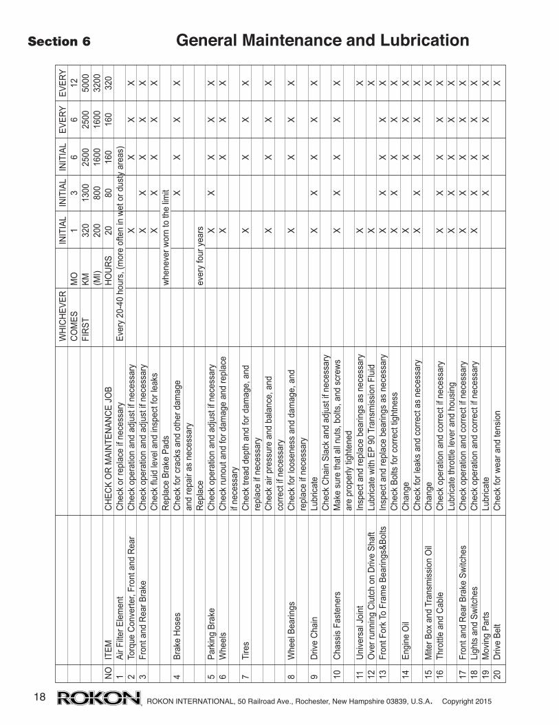
Section 6 General Maintenance and Lubrication
ROKON INTERNATIONAL, 50 Railroad Ave., Rochester, New Hampshire 03839, U.S.A. Copyright 2015 19
I. TRANSMISSION AND DRIVELINE REMOVAL PROCEDURE
Section 1, Procedure for Transmission Removal:
1. Elevate and secure the bike firmly to a non-moving stand. Bike should be elevated so that the rear wheel is not touching the ground. 2. Remove all side covers from the bike.
3. Close Fuel Tank Shut-Off Valve and Engine Fuel Valve. Disconnect fuel line and plug, if necessary. Remove fuel tank.
4. Remove front seat. This is accomplished by removing the two attaching bolts on each side of the front seat bracket and the bottom shock absorber attaching bolt. The whole assembly can be removed and put aside.
5. If transmission and driveline need to be removed, the rear wheel and rear fender will need to be taken off the bike. If only the transmission needs to be removed, the rear wheel may stay intact. See Section 7 Part II (page 21) for Drive Line Removal.
6. Remove the rear drive chain by locating the master link and separating it from the chain.
7. Remove the rear driveline roll pin. (If transmission and driveline are to be taken out as one unit, leave roll pin attached for ease of disassembly.) This is done by inserting a pin punch into the roll pin access hole (located under the front seat, which was removed), and driving the pin straight downward. Note: Rotate rear wheel until hole lines up.
8. Remove drive belt.
9. Remove driven clutch. Loosen the three Allen screws behind the clutch. Note: Driven clutch may be frozen on to the shaft. A small piece of wood and a mallet from behind the clutch should ease removal. Care must be taken not to damage clutch. Use pry bars if necessary.
10. Remove exhaust pipe. (Loosen two 12mm nuts. Pull muffler off engine seat. Pull muffler out of sleeve).
11. Remove rear brake caliper assembly. Take caution not to undo the brake line from the spring assembly. Disconnect cotter pin and back off brake tension. Remove brake caliper assembly and brake bracket as a complete unit. (Remove the two 1/2” transmission attaching bolts under the brake disc.). Slide brake disc off shaft. Take note the way the caliper and brake disc came off for reassembly.
Section 7 Repair Procedures
ROKON INTERNATIONAL, 50 Railroad Ave., Rochester, New Hampshire 03839, U.S.A. Copyright 201520
12. Remove all four transmission attaching bolts, three on the frame mount, and one next to the upper cross shaft. (Two should already be removed from the brake bracket as described in step 11).
At this point: Transmission can be removed, by moving left to right to loosen it from the driveline clutch, sliding back into fender well, and carefully turning sideways and pulling upward. Note: If the transmission can be shifted into 3rd gear, it will ease removal, by having the shift ball closer to the transmission.
Reverse disassembly procedure for assembling.
Note: Replace worn parts as needed. (ie. roll pins, worn nuts or bolts, drive belt, etc.) Use thread lock compound on transmission attaching bolts upon reassembly.
Section 2, Procedure for Transmission and Driveline Removal:
1. Follow steps 1-5 in Section 1.
2. Remove in order: rear wheel, tail section of muffler, and rear fender.
3. Remove the two carrier bearing bolts, which are located under the fuel tank.
4. Remove front chain guard cover, front drive chain, and headlight. Note: Ground wire for the headlight must be routed behind front miter box assembly.
5. Remove front brake caliper assembly. Remove two bolts that secure the assembly to the bracket. Swing out of the way. Remove brake disc.
6. Remove front miter box assembly. (This is done by removing the two 5/16-18 bolts from behind the miter box assembly.) Pull miter box assembly straight out of bore, with universal joint attached. Set aside.
7. Remove transmission assembly and drive line as one unit (Ease disassembly by making sure the transmission is shifted into the highest gear. Shift ball closest to the transmission.) Pull the assembly straight out of the bore.
8. Reverse procedure for reassembly.
Section 7 Repair Procedures
ROKON INTERNATIONAL, 50 Railroad Ave., Rochester, New Hampshire 03839, U.S.A. Copyright 2015 21
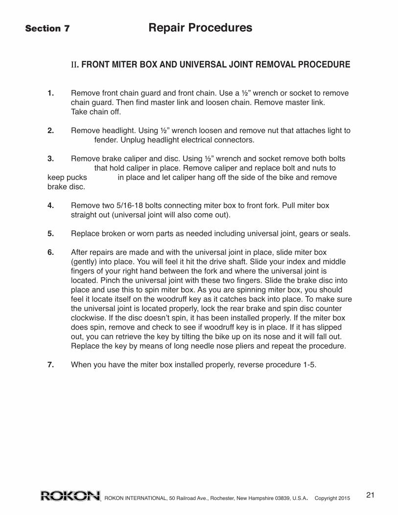
II. FRONT MITER BOX AND UNIVERSAL JOINT REMOVAL PROCEDURE
1. Remove front chain guard and front chain. Use a ½” wrench or socket to remove chain guard. Then find master link and loosen chain. Remove master link. Take chain off.
2. Remove headlight. Using ½” wrench loosen and remove nut that attaches light to fender. Unplug headlight electrical connectors.
3. Remove brake caliper and disc. Using ½” wrench and socket remove both bolts that hold caliper in place. Remove caliper and replace bolt and nuts to keep pucks in place and let caliper hang off the side of the bike and remove brake disc.
4. Remove two 5/16-18 bolts connecting miter box to front fork. Pull miter box straight out (universal joint will also come out).
5. Replace broken or worn parts as needed including universal joint, gears or seals.
6. After repairs are made and with the universal joint in place, slide miter box (gently) into place. You will feel it hit the drive shaft. Slide your index and middle fingers of your right hand between the fork and where the universal joint is located. Pinch the universal joint with these two fingers. Slide the brake disc into place and use this to spin miter box. As you are spinning miter box, you should feel it locate itself on the woodruff key as it catches back into place. To make sure the universal joint is located properly, lock the rear brake and spin disc counter clockwise. If the disc doesn’t spin, it has been installed properly. If the miter box does spin, remove and check to see if woodruff key is in place. If it has slipped out, you can retrieve the key by tilting the bike up on its nose and it will fall out. Replace the key by means of long needle nose pliers and repeat the procedure.
7. When you have the miter box installed properly, reverse procedure 1-5.
Section 7 Repair Procedures
ROKON INTERNATIONAL, 50 Railroad Ave., Rochester, New Hampshire 03839, U.S.A. Copyright 201522
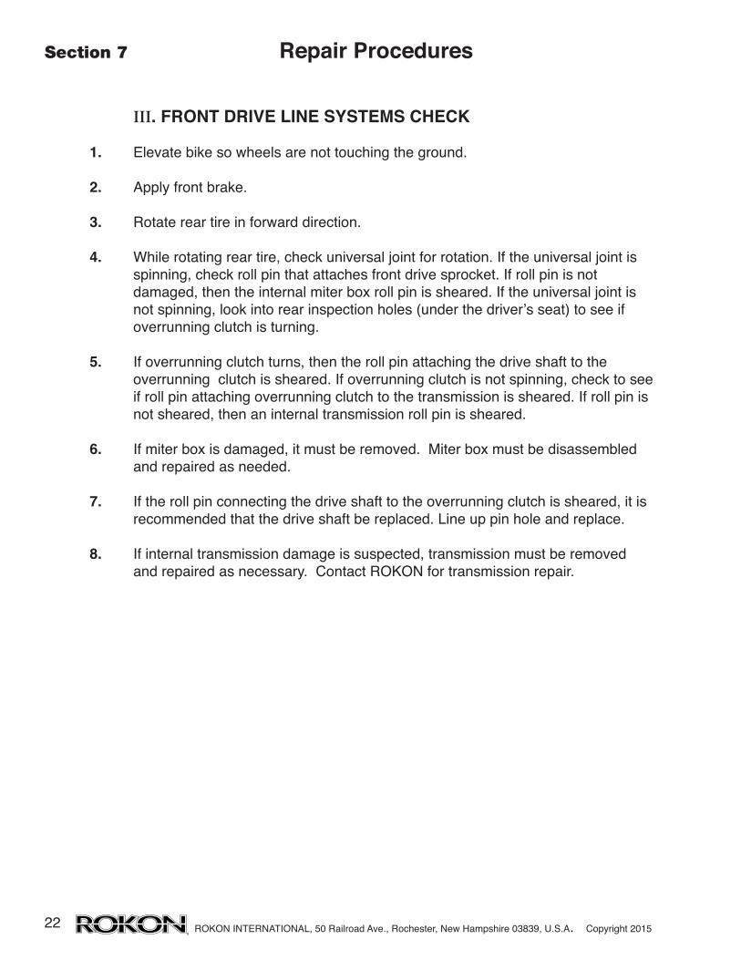
III. FRONT DRIVE LINE SYSTEMS CHECK
1. Elevate bike so wheels are not touching the ground.
2. Apply front brake.
3. Rotate rear tire in forward direction.
4. While rotating rear tire, check universal joint for rotation. If the universal joint is spinning, check roll pin that attaches front drive sprocket. If roll pin is not damaged, then the internal miter box roll pin is sheared. If the universal joint is not spinning, look into rear inspection holes (under the driver’s seat) to see if overrunning clutch is turning.
5. If overrunning clutch turns, then the roll pin attaching the drive shaft to the overrunning clutch is sheared. If overrunning clutch is not spinning, check to see if roll pin attaching overrunning clutch to the transmission is sheared. If roll pin is not sheared, then an internal transmission roll pin is sheared.
6. If miter box is damaged, it must be removed. Miter box must be disassembled and repaired as needed.
7. If the roll pin connecting the drive shaft to the overrunning clutch is sheared, it is recommended that the drive shaft be replaced. Line up pin hole and replace.
8. If internal transmission damage is suspected, transmission must be removed and repaired as necessary. Contact ROKON for transmission repair.
Section 7 Repair Procedures
ROKON INTERNATIONAL, 50 Railroad Ave., Rochester, New Hampshire 03839, U.S.A. Copyright 2015 23
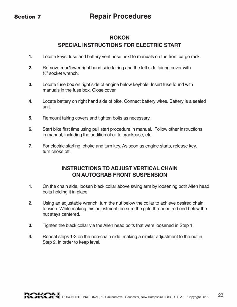
ROKONSPECIAL INSTRUCTIONS FOR ELECTRIC START
1. Locate keys, fuse and battery vent hose next to manuals on the front cargo rack.
2. Remove rear/lower right hand side fairing and the left side fairing cover with ½” socket wrench.
3. Locate fuse box on right side of engine below keyhole. Insert fuse found with manuals in the fuse box. Close cover.
4. Locate battery on right hand side of bike. Connect battery wires. Battery is a sealed unit.
5. Remount fairing covers and tighten bolts as necessary.
6. Start bike first time using pull start procedure in manual. Follow other instructions in manual, including the addition of oil to crankcase, etc.
7. For electric starting, choke and turn key. As soon as engine starts, release key, turn choke off.
INSTRUCTIONS TO ADJUST VERTICAL CHAIN ON AUTOGRAB FRONT SUSPENSION
1. On the chain side, loosen black collar above swing arm by loosening both Allen head bolts holding it in place.
2. Using an adjustable wrench, turn the nut below the collar to achieve desired chain tension. While making this adjustment, be sure the gold threaded rod end below the nut stays centered.
3. Tighten the black collar via the Allen head bolts that were loosened in Step 1.
4. Repeat steps 1-3 on the non-chain side, making a similar adjustment to the nut in Step 2, in order to keep level.
Section 7 Repair Procedures
ROKON INTERNATIONAL, 50 Railroad Ave., Rochester, New Hampshire 03839, U.S.A. Copyright 201524
Section 8 Torque and other Specification Charts
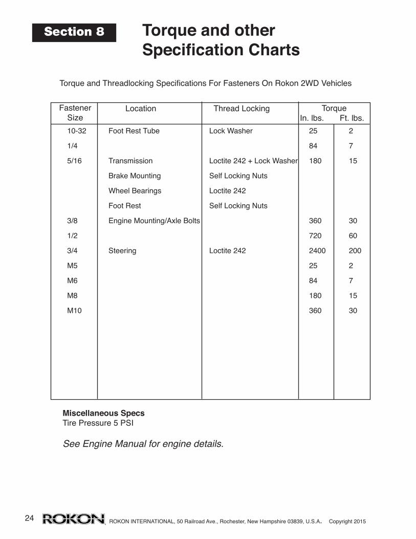
Torque and Threadlocking Specifications For Fasteners On Rokon 2WD Vehicles
Miscellaneous SpecsTire Pressure 5 PSI
See Engine Manual for engine details.
10-32 Foot Rest Tube Lock Washer 25 2
1/4 84 7
5/16 Transmission Loctite 242 + Lock Washer 180 15
Brake Mounting Self Locking Nuts
Wheel Bearings Loctite 242
Foot Rest Self Locking Nuts
3/8 Engine Mounting/Axle Bolts 360 30
1/2 720 60
3/4 Steering Loctite 242 2400 200
M5 25 2
M6 84 7
M8 180 15
M10 360 30
FastenerSize
Location Thread Locking TorqueIn. lbs. Ft. lbs.
ROKON INTERNATIONAL, 50 Railroad Ave., Rochester, New Hampshire 03839, U.S.A. Copyright 2015 25
Section 9 Limited Warranty
ROKON WARRANTY SYSTEM
ROKON International Inc. warranties to the original purchaser, new ROKON Utility Vehicles to be free of defects that are the result of faulty workmanship or material, for a period of one year from the date of purchase for new year model ROKONs only. In the case of competition machines, no warranty is expressed or implied. The entire risk to the quality and performance of competition machines is with the buyer.
Warranty will be honored through any authorized ROKON dealer or the factory. To validate warranty, Purchaser must: Complete and return Warranty Registration Card to ROKON International Inc. within ten (10) days of purchase.
Notify ROKON of any and all defects made within ten (10) days of malfunction and make machine immediately available for inspection at a place to be determined by ROKON.
Have warranty service performed by an authorized ROKON agent as directed by ROKON.
Warranty will not cover: Parts replaced as a result of normal wear. (ie. spark plugs, tires, tubes, and so forth) Parts subject to misuse, neglect, or modification. Parts damaged as a result of accident or collision. Machines used for rental and/or lease. Machines used in competitive events. Machine abuse.
ROKON International Inc.’s liability shall be limited to that set forth herein, and no other claims for consequential damage or injury to person or property will be admissible. All other conditions and warranties, statutory or otherwise, and whether expressed or implied, including, but not limited to, implied warranties of merchantability or fitness for a particular use, are hereby excluded. This implied warranty exclusion is not applicable in states having laws to the contrary.
ROKON INTERNATIONAL, 50 Railroad Ave., Rochester, New Hampshire 03839, U.S.A. Copyright 201526
Rokon International Inc. – Emission Control System Warranty Statement
YOUR WARRANTY RIGHTS AND OBLIGATIONS
The U.S. Environmental Protection Agency and Rokon International Inc. (hereinafter “Rokon”), are pleased to explain the emission control system warranty on your Off-Road Motorcycle. New off-road motor vehicles must be designed, built and equipped to meet U.S. EPA Federal and California anti-smog standards. Rokon must warrant the emission control system on your vehicle for 5,000 km, or at least 30 months, whichever comes first, provided that there has been no abuse, neglect or improper maintenance of your vehicle. This off-road motorcycle was designed to meet the emission standards for 10,000 km, or five years, whichever comes first.
Your emission control system may include parts such as the carburetor or fuel injection system, the ignition system, catalytic converter and engine computer, if it is equipped. Also included may be hoses, belts, connectors and other emission-related assemblies.
Where a warrantable condition exists, Rokon will repair your vehicle at no cost to you, including diagnosis, parts and labor.
If an emission-related part on your vehicle is defective, the part will be repaired or replaced by Rokon. This is your emission control system DEFECTS WARRANTY.
NOTICE! Use of any Rokon brand vehicle in any type of competitive event completely and absolutely voids this and all other warranties offered by Rokon.
OWNER’S WARRANTY RESPONSIBILITIES
As the vehicle owner, you are responsible for the performance of the required maintenance listed in your owner’s manual. Rokon recommends that you retain all receipts covering maintenance on your vehicle, but Rokon cannot deny warranty solely for the lack of receipts or for your failure to ensure the performance of all scheduled maintenance.
You are responsible for presenting your vehicle to the Rokon dealer as soon as a problem exists. The warranty repairs should be completed in a reasonable amount of time, not to exceed 30 days.
As the vehicle owner, you should be aware that Rokon may deny your warranty coverage if your vehicle or a part has failed due to abuse, neglect, improper maintenance or unapproved modifications.
If you use your vehicle in any type of competitive event, this warranty is immediately and completely void.
If you have any questions regarding your warranty rights and responsibilities, you should contact Rokon International Inc., 50 Railroad Avenue, Rochester, NH 03839, Phone: 603-335-3200, or the U.S. Environmental Protection Agency at 2000 Traverwood Drive, Ann Arbor, MI 48105.
ROKON INTERNATIONAL, 50 Railroad Ave., Rochester, New Hampshire 03839, U.S.A. Copyright 2015 27
Rokon International Inc. - Limited Warranty on Emission Control System
YOUR WARRANTY RIGHTS AND OBLIGATIONS
Rokon warrants that each new and later Rokon brand off-road motorcycle:
A. is designed, built and equipped so as to conform at the time of initial retail purchase with all applicable regulations of the United States Environmental Protection Agency, and the California Air Resources Board; and
B. is free from defects in material and workmanship which cause such vehicle to fail to conform to applicable regulations of the United States Environmental Protection Agency or the California Air Resources Board for the periods specified above.
I. Coverage. Warranty defects shall be remedied during customary business hours at any authorized Rokon dealer located within the United States of America in compliance with the Clean Air Act and applicable regulations of the United States Environmental Protection Agency and the California Air Resources Board. Any part or parts replaced under this warranty shall become the property of Rokon.
II. Limitations This Emission Control System Warranty shall not cover any of the following:
A. Repair or replacement as a result of (1) accident, (2) misuse,(3) repairs improperly performed or replacements improperly installed, (4) use of replacement parts or accessories not conforming to
specifications set forth by Rokon, which adversely affect performance and/or
(5) use in competitive racing or related events.
B. Inspections, replacement of parts and other services and adjustments required for required maintenance.
C. Any vehicle equipped with an odometer or hour meter on which the odometer mileage or hour meter reading has been changed so that actual mileage cannot be readily determined.
III. Limited Liability A. The liability of Rokon under this Emission Control System Warranty is limited solely to the
remedying of defects in material or workmanship by an authorized Rokon dealer at its place of business during customary business hours. This warranty does not cover inconvenience or loss of use of the vehicle or transportation of the vehicle to or from the Rokon dealer. Rokon shall not be liable for any other expenses, loss or damage, whether direct, indidental, consequential or exemplary arising in connection with the sale or use of or inability to use the Rokon brand vehicle for any purpose. Some states do not allow the exclusion or limitation of any incidental or consequential damages, so the above limitations may not apply to you.
ROKON INTERNATIONAL, 50 Railroad Ave., Rochester, New Hampshire 03839, U.S.A. Copyright 201528
Illustrated Parts Manual Index of Illustrations
Page Nomenclature 27 Brakes 28 Chain 29 Decals 30 Electrical 31 Honda Engine 32-33 Kohler Engine 34 Kohler Airbox 35-36 Frame 37 Front Fork 38 Front Cargo Rack 39 Fuel Tank 40 Muffler 41-42 Handle Bar 43 Pullstarter 44 Front Seat 45 Rear Seat 46 Torque Converter Drive Pulley 47 Torque Converter Driven Pulley 48 Tow Bar 49 Transmission Complete 50 Transmission with Attachments 51-52 Transmission in Sequence 53 Miter Box 54 Transmission to Miter Box 55 Aluminum Wheels 56 Steel Wheels 57-58 Auto Grab Front Suspension 59 Wiring Diagram
Section 10
ROKON INTERNATIONAL, 50 Railroad Ave., Rochester, New Hampshire 03839, U.S.A. Copyright 2015 29
BrakeSection 10
Item Part Number Name Description Qty 1 0701-1062 Piston 1 2 0701-1004 O-Ring, Buna-N 1 9 0701-1006 Screw, Flat Head Slotted 2 10 0701-1005 Puck 1 12 0701-1003 O-Ring, Buna-N 1 13 0708-1001 Housing, Pneumatic, Retractable 1 14 0701-1007 Washer 4 15 0701-1008 Nut, Flexloc 2 18 3030-1007 Hex Bolt 2 22 0701-1032 Puck, Dead Side 1
ROKON INTERNATIONAL, 50 Railroad Ave., Rochester, New Hampshire 03839, U.S.A. Copyright 201530
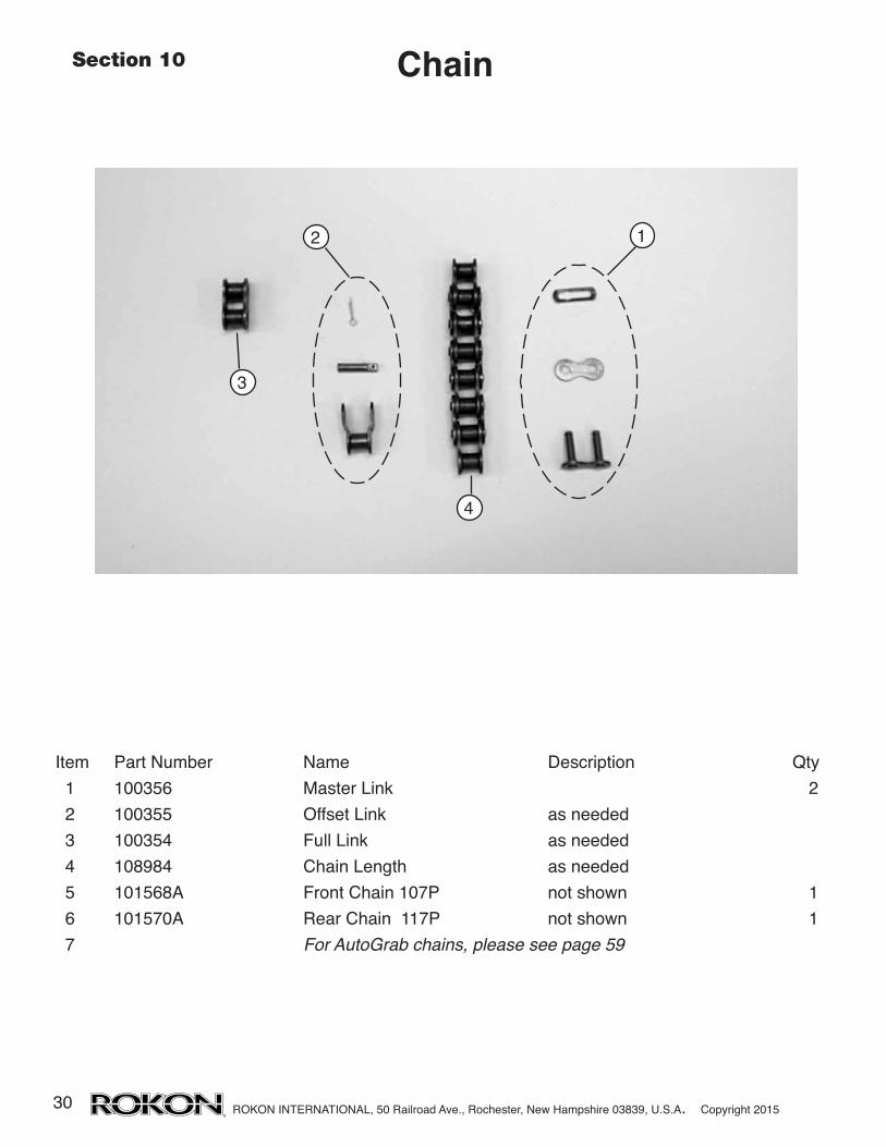
Item Part Number Name Description Qty 1 100356 Master Link 2 2 100355 Offset Link as needed 3 100354 Full Link as needed 4 108984 Chain Length as needed 5 101568A Front Chain 107P not shown 1 6 101570A Rear Chain 117P not shown 1 7 For AutoGrab chains, please see page 59
ChainSection 10
1
4
2
3
ROKON INTERNATIONAL, 50 Railroad Ave., Rochester, New Hampshire 03839, U.S.A. Copyright 2015 31
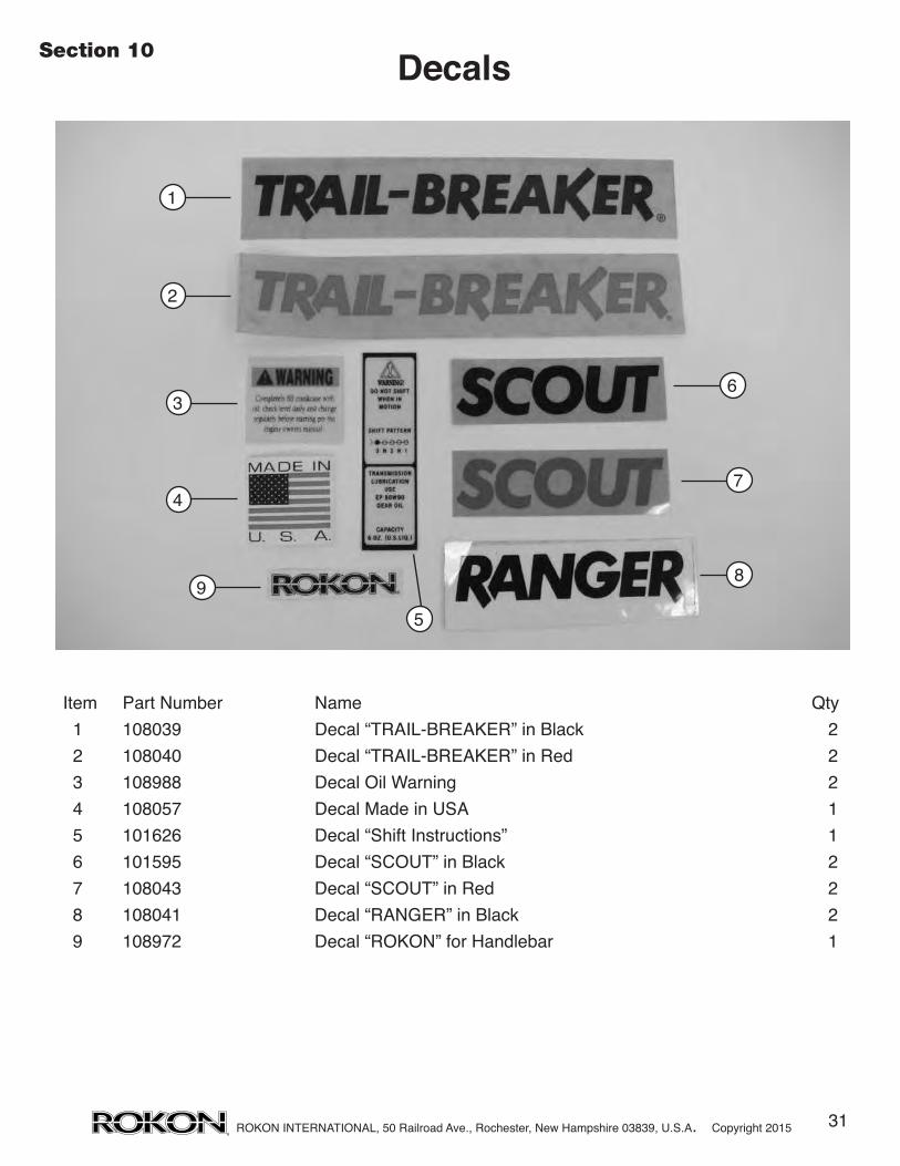
Item Part Number Name Qty 1 108039 Decal “TRAIL-BREAKER” in Black 2 2 108040 Decal “TRAIL-BREAKER” in Red 2 3 108988 Decal Oil Warning 2 4 108057 Decal Made in USA 1 5 101626 Decal “Shift Instructions” 1 6 101595 Decal “SCOUT” in Black 2 7 108043 Decal “SCOUT” in Red 2 8 108041 Decal “RANGER” in Black 2 9 108972 Decal “ROKON” for Handlebar 1
DecalsSection 10
7
98
6
2
3
5
1
4
ROKON INTERNATIONAL, 50 Railroad Ave., Rochester, New Hampshire 03839, U.S.A. Copyright 201532
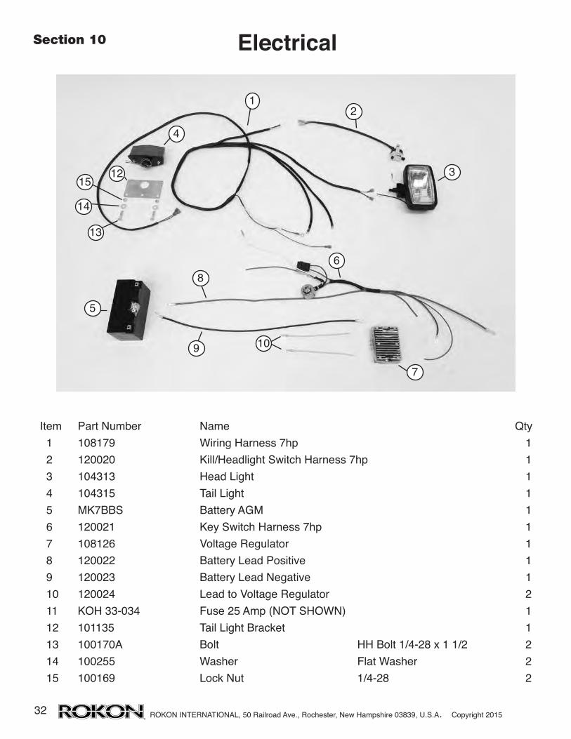
Item Part Number Name Qty 1 108179 Wiring Harness 7hp 1 2 120020 Kill/Headlight Switch Harness 7hp 1 3 104313 Head Light 1 4 104315 Tail Light 1 5 MK7BBS Battery AGM 1 6 120021 Key Switch Harness 7hp 1 7 108126 Voltage Regulator 1 8 120022 Battery Lead Positive 1 9 120023 Battery Lead Negative 1 10 120024 Lead to Voltage Regulator 2 11 KOH 33-034 Fuse 25 Amp (NOT SHOWN) 1 12 101135 Tail Light Bracket 1 13 100170A Bolt HH Bolt 1/4-28 x 1 1/2 2 14 100255 Washer Flat Washer 2 15 100169 Lock Nut 1/4-28 2
10
12
13
14
15
6
3
ElectricalSection 10
4
12
5
9
8
7
ROKON INTERNATIONAL, 50 Railroad Ave., Rochester, New Hampshire 03839, U.S.A. Copyright 2015 33
Kohler EngineSection 10
1
18
2
17
16
14
15
13
6
910
4
5
8
11
12
30
1920
21
27
7
3
26
23
25
24
22
ROKON INTERNATIONAL, 50 Railroad Ave., Rochester, New Hampshire 03839, U.S.A. Copyright 201534
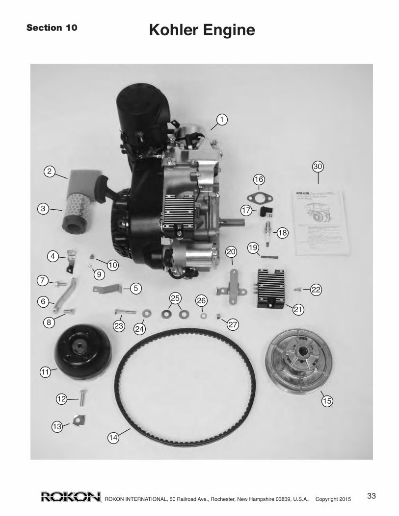
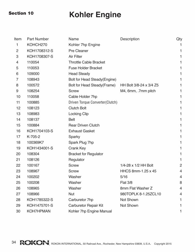
Item Part Number Name Description Qty 1 KOHCH270 Kohler 7hp Engine 1 2 KOH1708312-S Pre Cleaner 1 3 KOH1708307-S Air Filter 1 4 110054 Throttle Cable Bracket 1 5 110053 Fuse Holder Bracket 1 6 109000 Head Steady 1 7 108943 Bolt for Head Steady(Engine) 1 8 100572 Bolt for Head Steady(Frame) HH Bolt 3/8-24 x 3/4 Z5 1 9 108254 Screw M4, 6mm, .7mm pitch 1 10 110058 Cable Holder 7hp 1 11 100885 Driven Torque Converter(Clutch) 1 12 108123 Clutch Bolt 1 13 108983 Locking Clip 1 14 108137 Belt 1 15 100884 Rear Driven Clutch 1 16 KOH1704103-S Exhaust Gasket 1 17 K-705-2 Sparky 1 18 100369K7 Spark Plug 7hp 1 19 KOH1434001-S Crank Key 1 20 108304 Bracket for Regulator 1 21 108126 Regulator 1 22 100167 Screw 1/4-28 x 1/2 HH Bolt 2 23 108967 Screw HHCS 8mm-1.25 x 45 4 24 100202 Washer 5/16 4 25 100208 Washer Flat 3/8 8 26 108965 Washer 8mm Flat Washer Z 4 27 108966 Nut 980TOPLK 8-1.25ZCL10 4 28 KOH1785322-S Carburetor 7hp Not Shown 1 29 KOH1475701-S Carburetor Repair Kit Not Shown 1 30 KOH7HPMAN Kohler 7hp Engine Manual 1
Kohler EngineSection 10
ROKON INTERNATIONAL, 50 Railroad Ave., Rochester, New Hampshire 03839, U.S.A. Copyright 2015 35
Kohler Air BoxSection 10
1
2
3 4
5
7
6
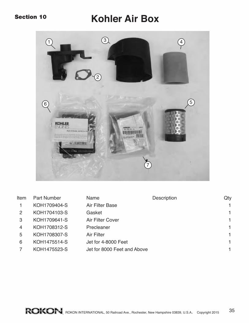
Item Part Number Name Description Qty 1 KOH1709404-S Air Filter Base 1 2 KOH1704103-S Gasket 1 3 KOH1709641-S Air Filter Cover 1 4 KOH1708312-S Precleaner 1 5 KOH1708307-S Air Filter 1 6 KOH1475514-S Jet for 4-8000 Feet 1 7 KOH1475523-S Jet for 8000 Feet and Above 1
ROKON INTERNATIONAL, 50 Railroad Ave., Rochester, New Hampshire 03839, U.S.A. Copyright 201536
FrameSection 10
24
1
10
23
24
1126
27
1415 3
9
812
6
13
19
18
1716
20
22
5
7
ROKON INTERNATIONAL, 50 Railroad Ave., Rochester, New Hampshire 03839, U.S.A. Copyright 2015 37
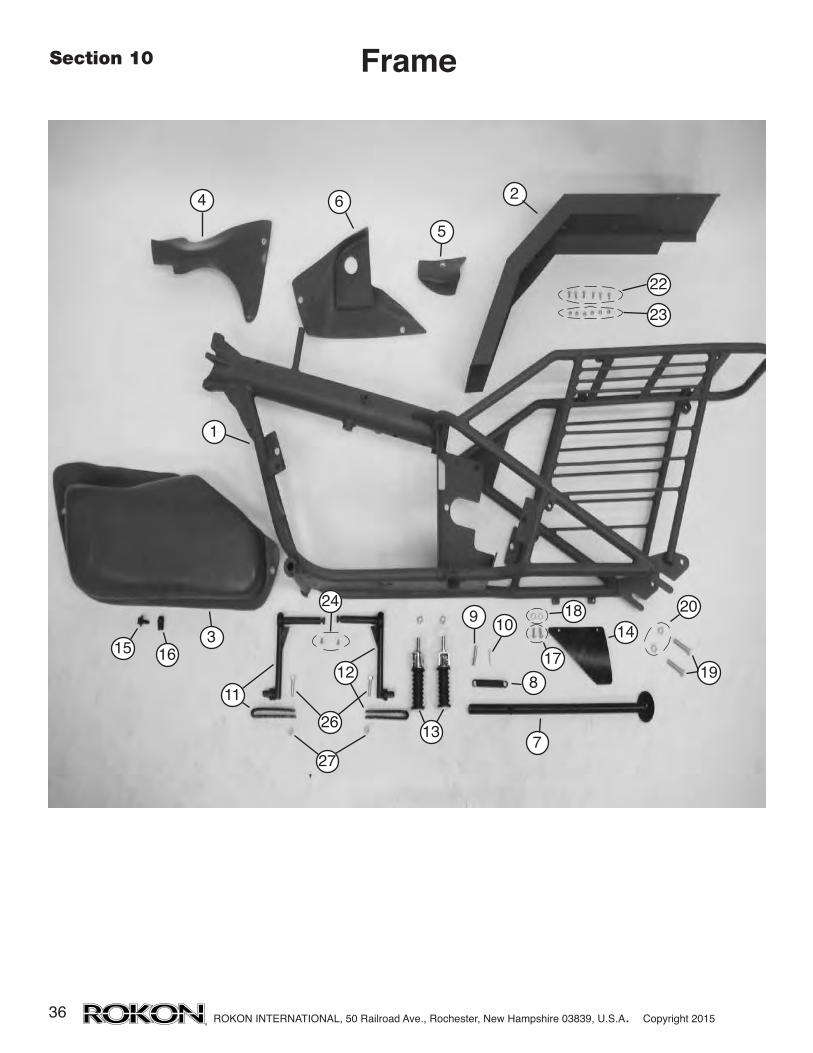
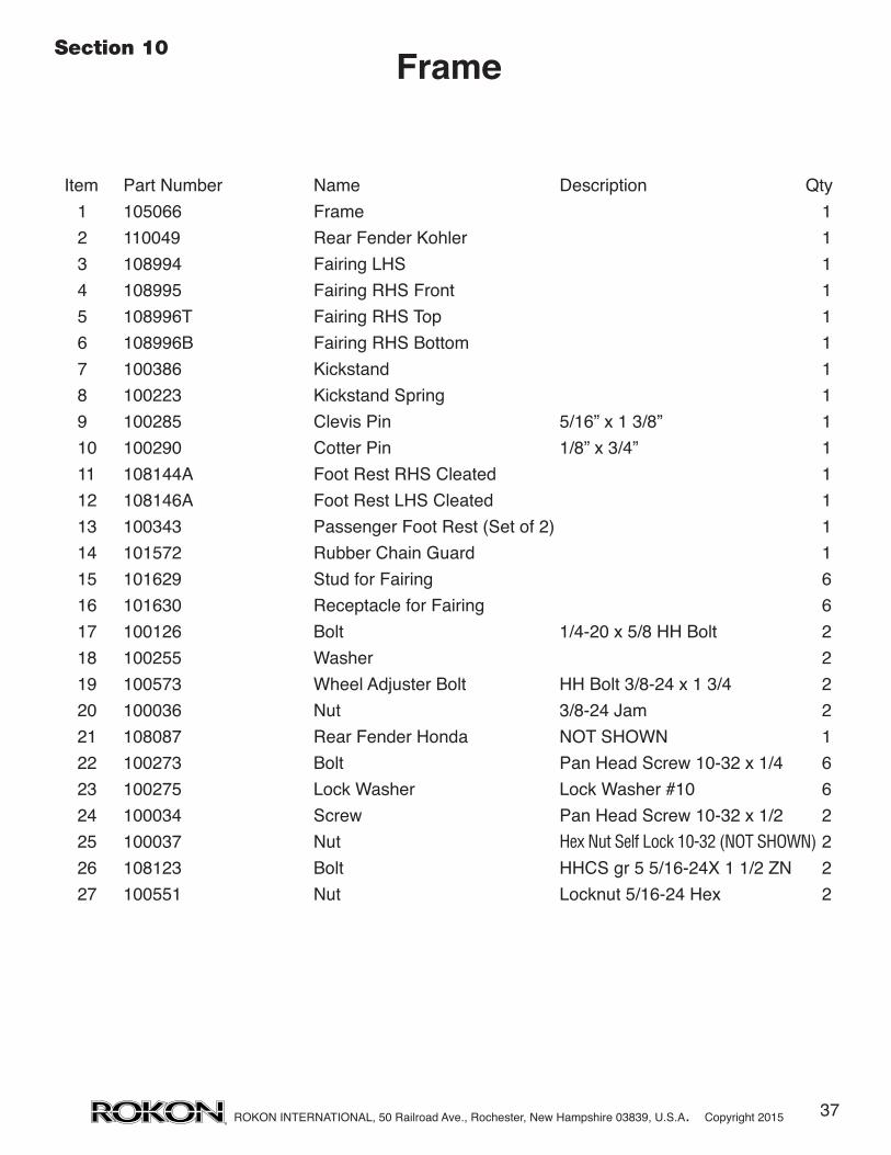
Item Part Number Name Description Qty 1 105066 Frame 1 2 110049 Rear Fender Kohler 1 3 108994 Fairing LHS 1 4 108995 Fairing RHS Front 1 5 108996T Fairing RHS Top 1 6 108996B Fairing RHS Bottom 1 7 100386 Kickstand 1 8 100223 Kickstand Spring 1 9 100285 Clevis Pin 5/16” x 1 3/8” 1 10 100290 Cotter Pin 1/8” x 3/4” 1 11 108144A Foot Rest RHS Cleated 1 12 108146A Foot Rest LHS Cleated 1 13 100343 Passenger Foot Rest (Set of 2) 1 14 101572 Rubber Chain Guard 1 15 101629 Stud for Fairing 6 16 101630 Receptacle for Fairing 6 17 100126 Bolt 1/4-20 x 5/8 HH Bolt 2 18 100255 Washer 2 19 100573 Wheel Adjuster Bolt HH Bolt 3/8-24 x 1 3/4 2 20 100036 Nut 3/8-24 Jam 2 21 108087 Rear Fender Honda NOT SHOWN 1 22 100273 Bolt Pan Head Screw 10-32 x 1/4 6 23 100275 Lock Washer Lock Washer #10 6 24 100034 Screw Pan Head Screw 10-32 x 1/2 2 25 100037 Nut Hex Nut Self Lock 10-32 (NOT SHOWN) 2 26 108123 Bolt HHCS gr 5 5/16-24X 1 1/2 ZN 2 27 100551 Nut Locknut 5/16-24 Hex 2
FrameSection 10
ROKON INTERNATIONAL, 50 Railroad Ave., Rochester, New Hampshire 03839, U.S.A. Copyright 201538
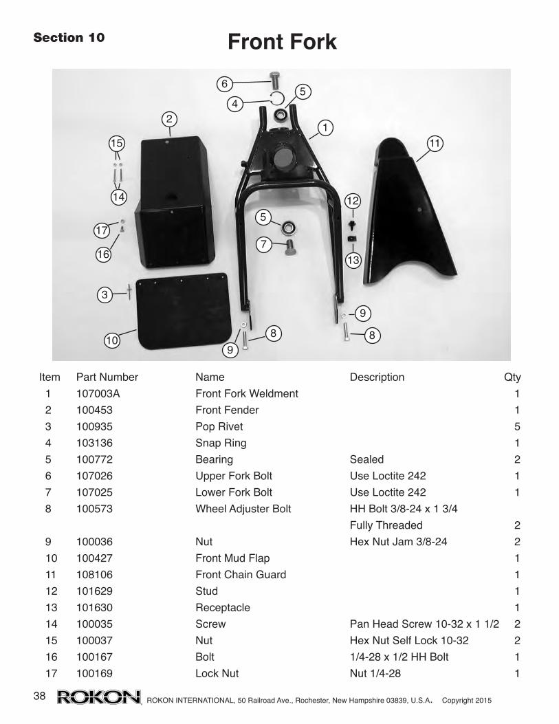
Item Part Number Name Description Qty 1 107003A Front Fork Weldment 1 2 100453 Front Fender 1 3 100935 Pop Rivet 5 4 103136 Snap Ring 1 5 100772 Bearing Sealed 2 6 107026 Upper Fork Bolt Use Loctite 242 1 7 107025 Lower Fork Bolt Use Loctite 242 1 8 100573 Wheel Adjuster Bolt HH Bolt 3/8-24 x 1 3/4 Fully Threaded 2 9 100036 Nut Hex Nut Jam 3/8-24 2 10 100427 Front Mud Flap 1 11 108106 Front Chain Guard 1 12 101629 Stud 1 13 101630 Receptacle 1 14 100035 Screw Pan Head Screw 10-32 x 1 1/2 2 15 100037 Nut Hex Nut Self Lock 10-32 2 16 100167 Bolt 1/4-28 x 1/2 HH Bolt 1 17 100169 Lock Nut Nut 1/4-28 1
1
56
11
12
13
5
7
98
9
810
3
16
17
14
15
4
Front ForkSection 10
2
ROKON INTERNATIONAL, 50 Railroad Ave., Rochester, New Hampshire 03839, U.S.A. Copyright 2015 39
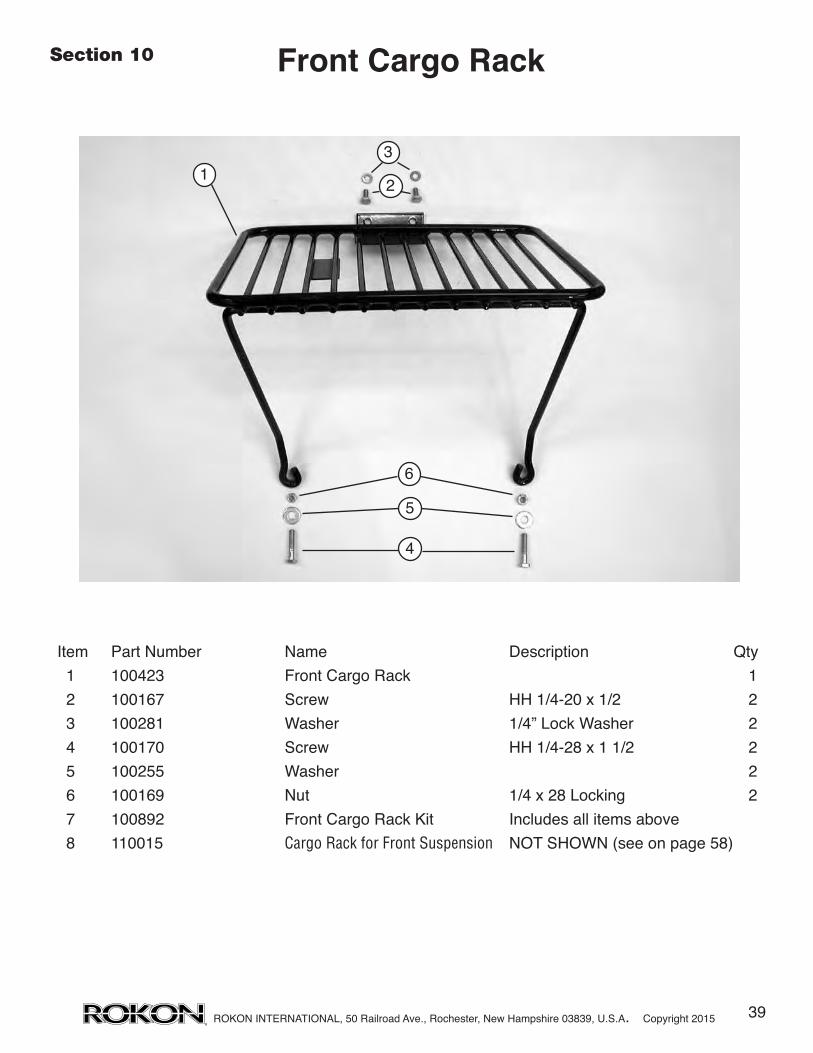
Item Part Number Name Description Qty 1 100423 Front Cargo Rack 1 2 100167 Screw HH 1/4-20 x 1/2 2 3 100281 Washer 1/4” Lock Washer 2 4 100170 Screw HH 1/4-28 x 1 1/2 2 5 100255 Washer 2 6 100169 Nut 1/4 x 28 Locking 2 7 100892 Front Cargo Rack Kit Includes all items above 8 110015 Cargo Rack for Front Suspension NOT SHOWN (see on page 58)
Front Cargo RackSection 10
1 2
3
6
5
4
ROKON INTERNATIONAL, 50 Railroad Ave., Rochester, New Hampshire 03839, U.S.A. Copyright 201540
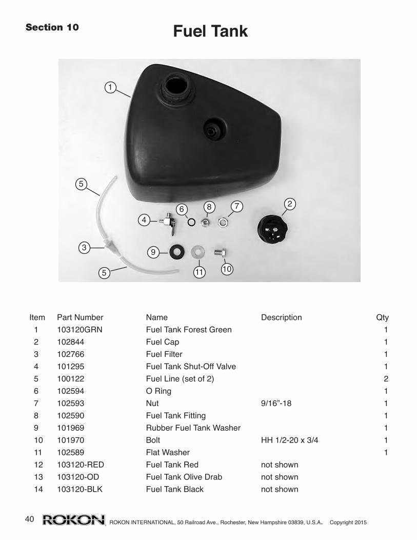
Item Part Number Name Description Qty 1 103120GRN Fuel Tank Forest Green 1 2 102844 Fuel Cap 1 3 102766 Fuel Filter 1 4 101295 Fuel Tank Shut-Off Valve 1 5 100122 Fuel Line (set of 2) 2 6 102594 O Ring 1 7 102593 Nut 9/16”-18 1 8 102590 Fuel Tank Fitting 1 9 101969 Rubber Fuel Tank Washer 1 10 101970 Bolt HH 1/2-20 x 3/4 1 11 102589 Flat Washer 1 12 103120-RED Fuel Tank Red not shown 13 103120-OD Fuel Tank Olive Drab not shown 14 103120-BLK Fuel Tank Black not shown
Fuel TankSection 10
1
5
3
5
4
2
9
11 10
786
ROKON INTERNATIONAL, 50 Railroad Ave., Rochester, New Hampshire 03839, U.S.A. Copyright 2015 41
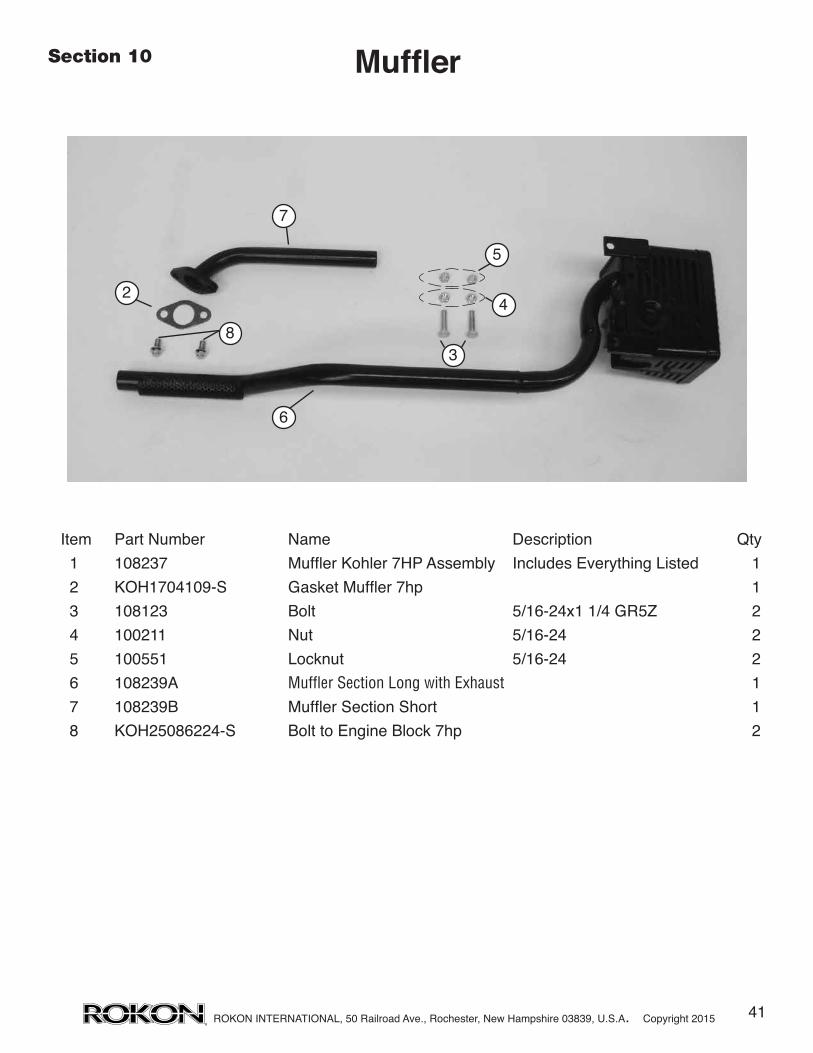
Item Part Number Name Description Qty 1 108237 Muffler Kohler 7HP Assembly Includes Everything Listed 1 2 KOH1704109-S Gasket Muffler 7hp 1 3 108123 Bolt 5/16-24x1 1/4 GR5Z 2 4 100211 Nut 5/16-24 2 5 100551 Locknut 5/16-24 2 6 108239A Muffler Section Long with Exhaust 1 7 108239B Muffler Section Short 1 8 KOH25086224-S Bolt to Engine Block 7hp 2
MufflerSection 10
7
2
84
5
3
6
ROKON INTERNATIONAL, 50 Railroad Ave., Rochester, New Hampshire 03839, U.S.A. Copyright 201542
20
21
1113
14 14
151517
18
19
18
17
16
13
12
221
5
67
8
9
8
4
22
3
Section 10 Handle Bar
19
ROKON INTERNATIONAL, 50 Railroad Ave., Rochester, New Hampshire 03839, U.S.A. Copyright 2015 43
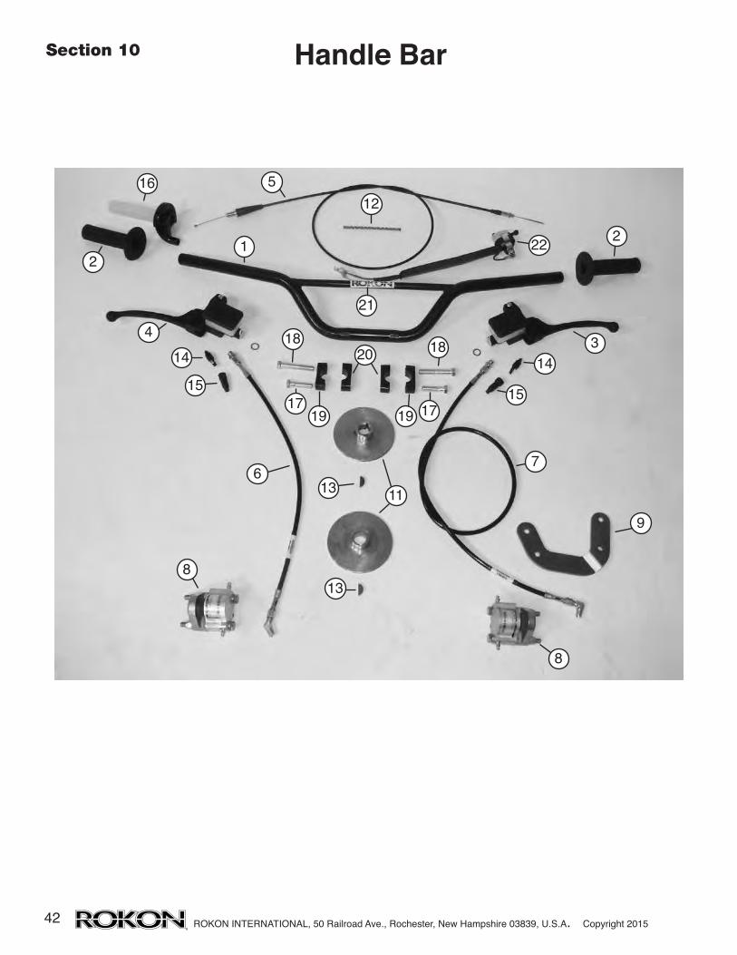
Item Part Number Name Description Qty 1 100466 Handlebar 1 2 100071 Grip Set 1 3 108957 Brake Lever LH 1 4 108958 Brake Lever RH 1 5 107037 Throttle Cable 7hp 1 6 108960 Front Brake Hose 1 7 108961 Rear Brake Hose 1 8 108013 Brake Caliper Hydraulic 2 9 110032 Rear Brake Bracket 7hp 1 10 108001 Rear Brake Bracket (Honda Only) not shown 1 11 100610 Brake Disc 2 12 100599 Throttle Spring 1 13 100043 Woodruff Key #9 2 14 104309 Brake Switch 2 15 107033 Boot 2 16 103113 Twist Grip 1 17 108985 Handlebar Clamp Bolt Short 3/8-16 x 1 1/2 2 18 108986 Handlebar Clamp Bolt Long 3/8-24 x 2 1/4 2 19 108115 Handlebar Clamp Upper 2 20 108116 Handlebar Clamp Lower 2 21 108972 ROKON Decal 1 22 100191 Shut Off Switch 1
Section 10 Handle Bar
ROKON INTERNATIONAL, 50 Railroad Ave., Rochester, New Hampshire 03839, U.S.A. Copyright 201544
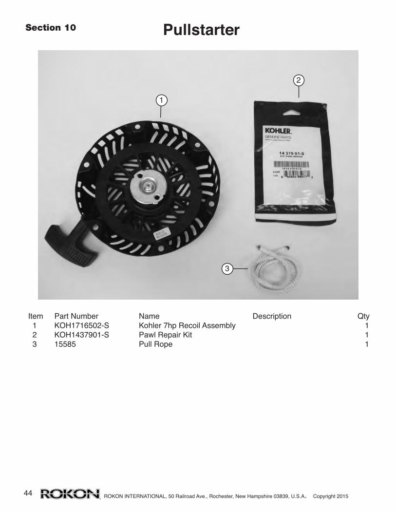
Item Part Number Name Description Qty 1 KOH1716502-S Kohler 7hp Recoil Assembly 1 2 KOH1437901-S Pawl Repair Kit 1 3 15585 Pull Rope 1
PullstarterSection 10
1
3
2
ROKON INTERNATIONAL, 50 Railroad Ave., Rochester, New Hampshire 03839, U.S.A. Copyright 2015 45
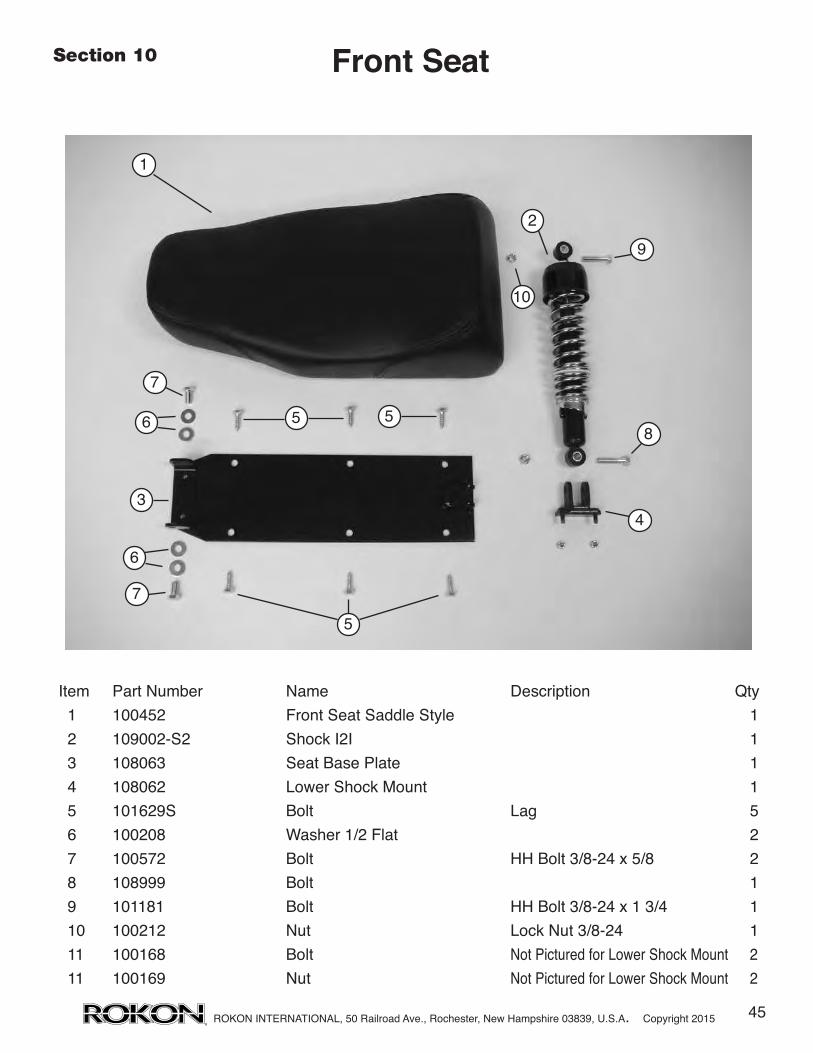
Item Part Number Name Description Qty 1 100452 Front Seat Saddle Style 1 2 109002-S2 Shock I2I 1 3 108063 Seat Base Plate 1 4 108062 Lower Shock Mount 1 5 101629S Bolt Lag 5 6 100208 Washer 1/2 Flat 2 7 100572 Bolt HH Bolt 3/8-24 x 5/8 2 8 108999 Bolt 1 9 101181 Bolt HH Bolt 3/8-24 x 1 3/4 1 10 100212 Nut Lock Nut 3/8-24 1 11 100168 Bolt Not Pictured for Lower Shock Mount 2 11 100169 Nut Not Pictured for Lower Shock Mount 2
Front SeatSection 10
1
29
10
7
6
3
6
7
5 5
5
4
8
ROKON INTERNATIONAL, 50 Railroad Ave., Rochester, New Hampshire 03839, U.S.A. Copyright 201546
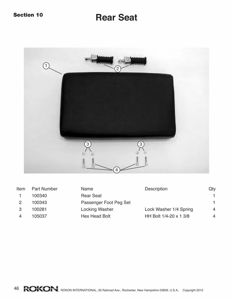
Item Part Number Name Description Qty 1 100340 Rear Seat 1 2 100343 Passenger Foot Peg Set 1 3 100281 Locking Washer Lock Washer 1/4 Spring 4 4 105037 Hex Head Bolt HH Bolt 1/4-20 x 1 3/8 4
Rear SeatSection 10
21
3 3
4
ROKON INTERNATIONAL, 50 Railroad Ave., Rochester, New Hampshire 03839, U.S.A. Copyright 2015 47
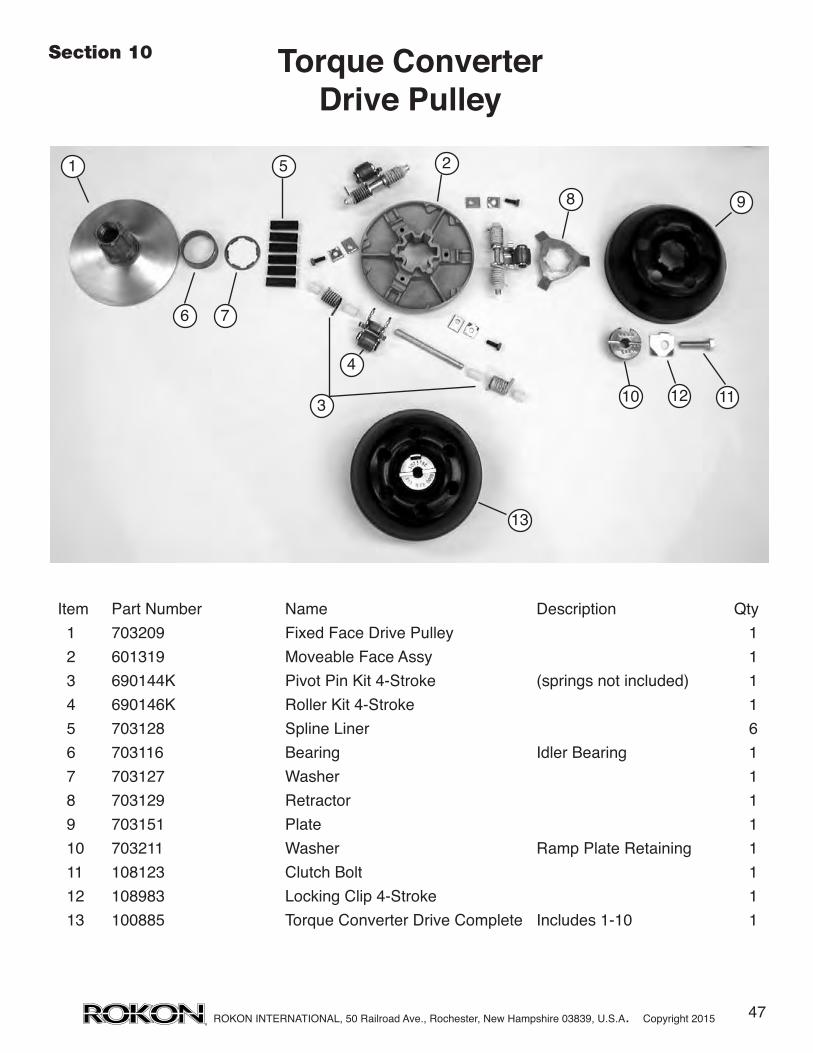
Item Part Number Name Description Qty 1 703209 Fixed Face Drive Pulley 1 2 601319 Moveable Face Assy 1 3 690144K Pivot Pin Kit 4-Stroke (springs not included) 1 4 690146K Roller Kit 4-Stroke 1 5 703128 Spline Liner 6 6 703116 Bearing Idler Bearing 1 7 703127 Washer 1 8 703129 Retractor 1 9 703151 Plate 1 10 703211 Washer Ramp Plate Retaining 1 11 108123 Clutch Bolt 1 12 108983 Locking Clip 4-Stroke 1 13 100885 Torque Converter Drive Complete Includes 1-10 1
Torque Converter Drive Pulley
Section 10
1 25
6 7
8 9
111210
13
4
3
ROKON INTERNATIONAL, 50 Railroad Ave., Rochester, New Hampshire 03839, U.S.A. Copyright 201548
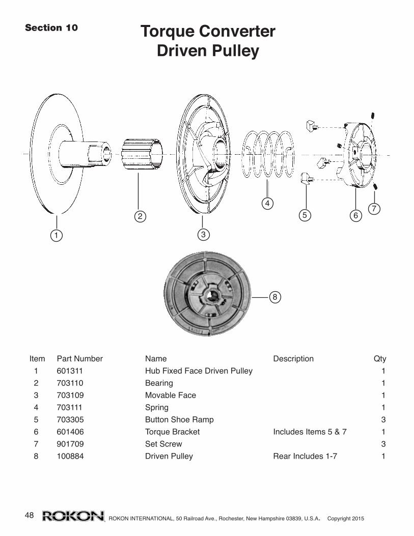
Item Part Number Name Description Qty 1 601311 Hub Fixed Face Driven Pulley 1 2 703110 Bearing 1 3 703109 Movable Face 1 4 703111 Spring 1 5 703305 Button Shoe Ramp 3 6 601406 Torque Bracket Includes Items 5 & 7 1 7 901709 Set Screw 3 8 100884 Driven Pulley Rear Includes 1-7 1
Torque Converter Driven Pulley
Section 10
1 3
24
5 67
8
ROKON INTERNATIONAL, 50 Railroad Ave., Rochester, New Hampshire 03839, U.S.A. Copyright 2015 49
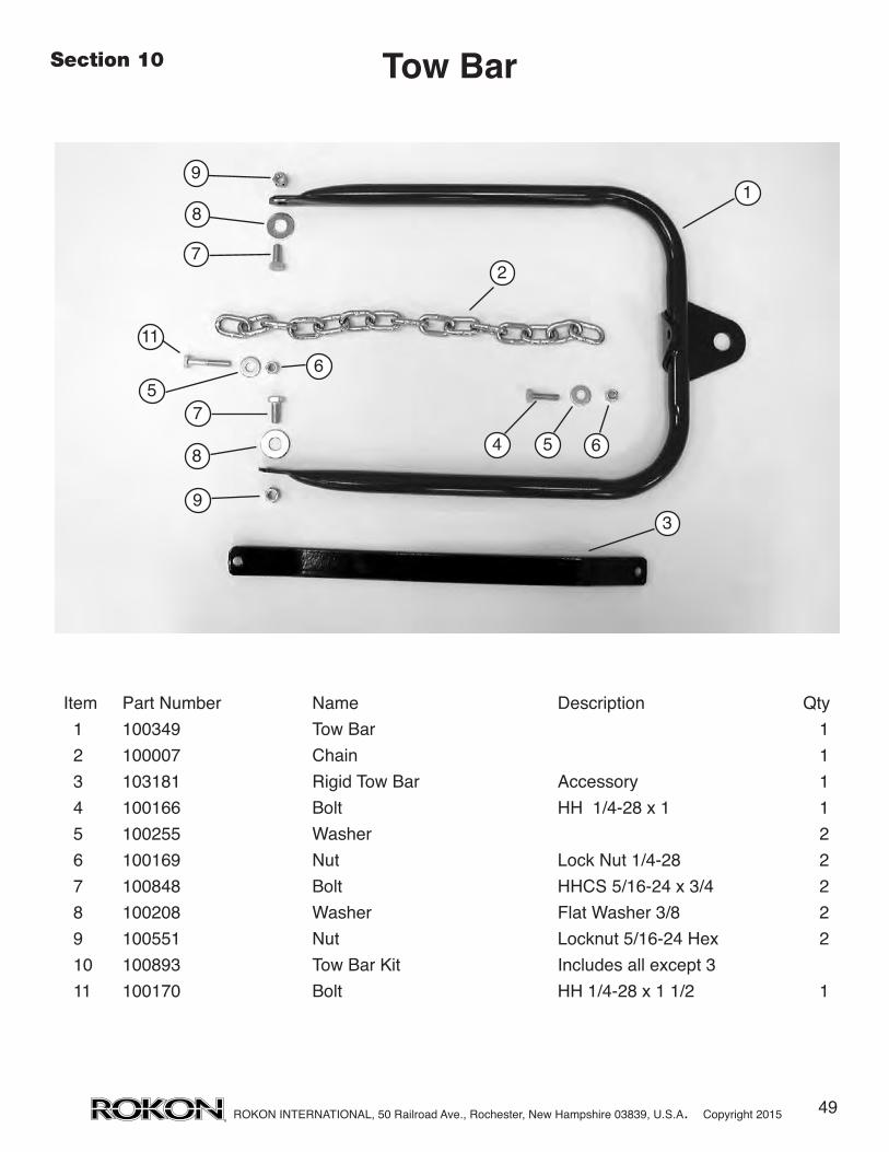
Item Part Number Name Description Qty 1 100349 Tow Bar 1 2 100007 Chain 1 3 103181 Rigid Tow Bar Accessory 1 4 100166 Bolt HH 1/4-28 x 1 1 5 100255 Washer 2 6 100169 Nut Lock Nut 1/4-28 2 7 100848 Bolt HHCS 5/16-24 x 3/4 2 8 100208 Washer Flat Washer 3/8 2 9 100551 Nut Locknut 5/16-24 Hex 2 10 100893 Tow Bar Kit Includes all except 3 11 100170 Bolt HH 1/4-28 x 1 1/2 1
Tow BarSection 10
1
2
3
9
8
7
9
8
7
65
4 5 6
11
ROKON INTERNATIONAL, 50 Railroad Ave., Rochester, New Hampshire 03839, U.S.A. Copyright 201550
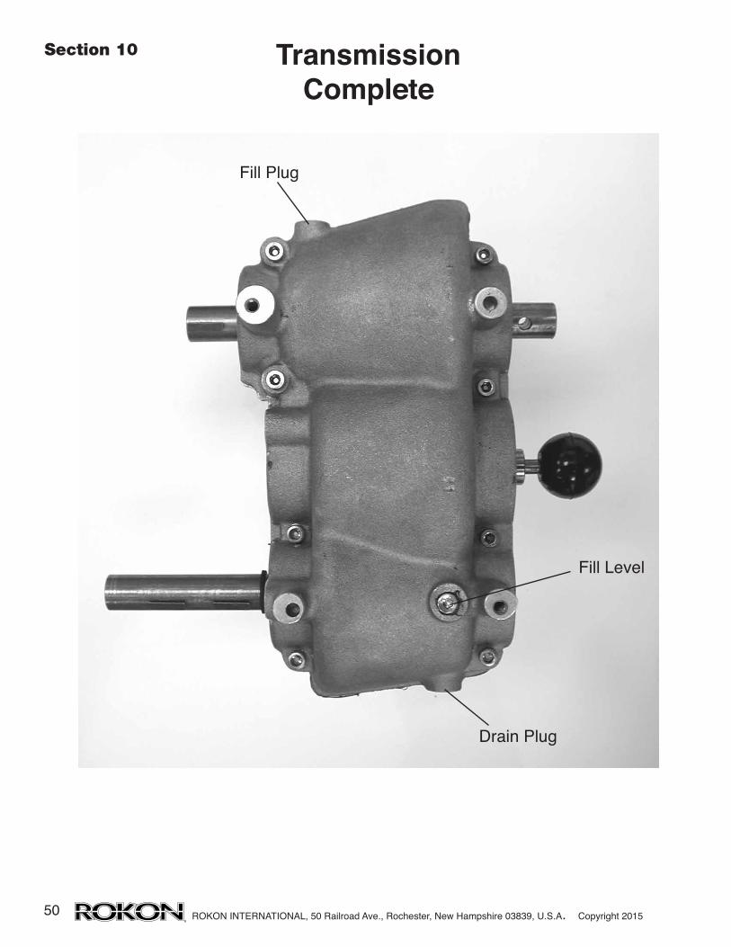
Fill Level
Transmission Complete
Section 10
Fill Plug
Drain Plug
ROKON INTERNATIONAL, 50 Railroad Ave., Rochester, New Hampshire 03839, U.S.A. Copyright 2015 51
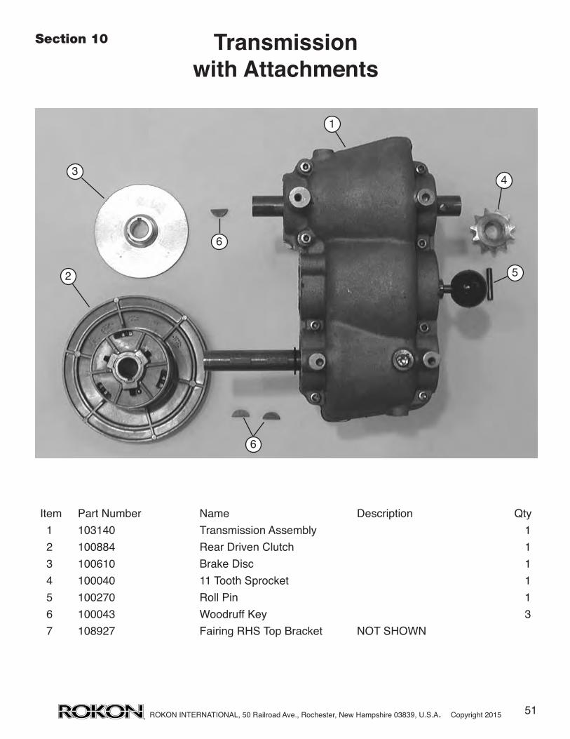
Item Part Number Name Description Qty 1 103140 Transmission Assembly 1 2 100884 Rear Driven Clutch 1 3 100610 Brake Disc 1 4 100040 11 Tooth Sprocket 1 5 100270 Roll Pin 1 6 100043 Woodruff Key 3 7 108927 Fairing RHS Top Bracket NOT SHOWN
Transmission with Attachments
Section 10
1
4
5
6
3
6
2
ROKON INTERNATIONAL, 50 Railroad Ave., Rochester, New Hampshire 03839, U.S.A. Copyright 201552
Transmission in Sequence
Section 10
1
23
6
41
38
37
37
38
37
2
13
11
23
2
5
11
2021
1210
7
8
7
89
42
14 17
5 15 16 18 19
24 25 26
22
27
2 6 5 10 28 31 5 40
44
30 32
3329
34 35
4
5
5
5
6
66
42
43
ROKON INTERNATIONAL, 50 Railroad Ave., Rochester, New Hampshire 03839, U.S.A. Copyright 2015 53
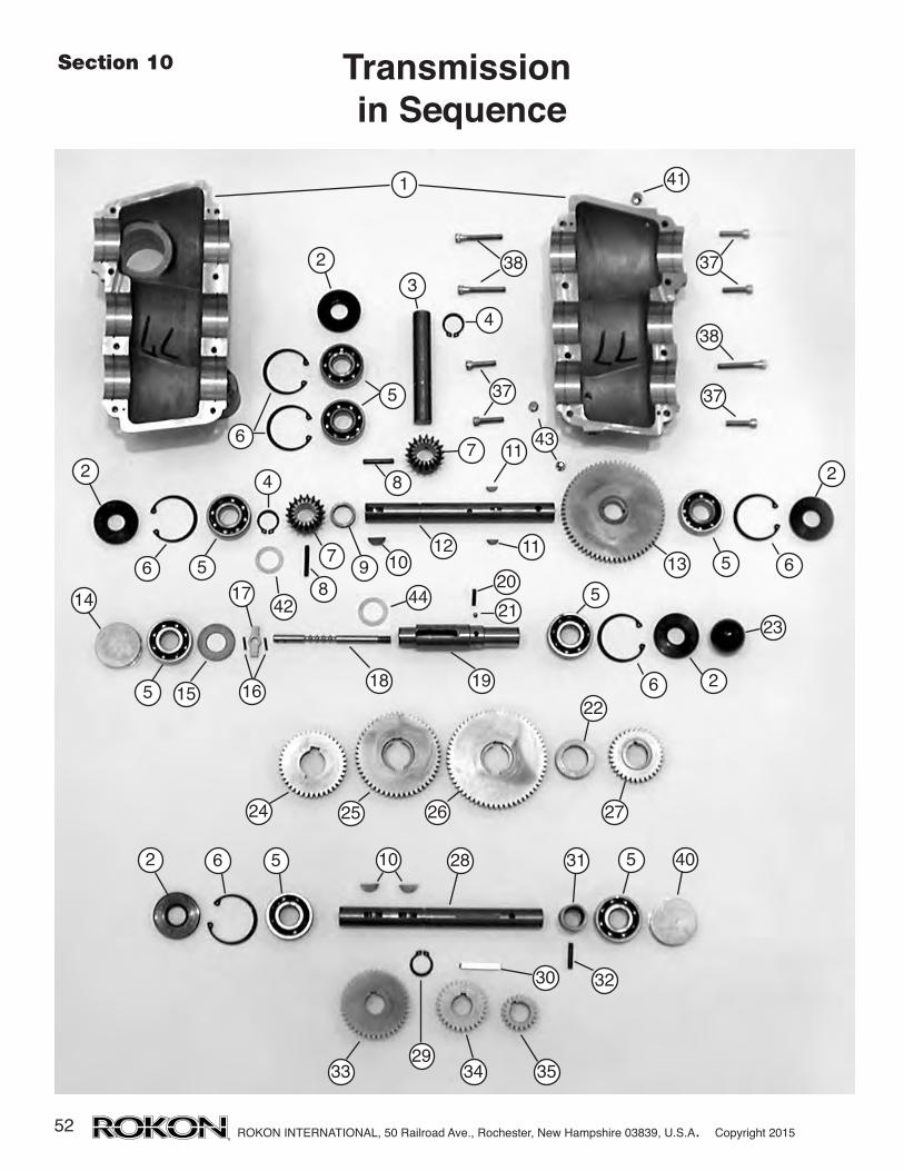
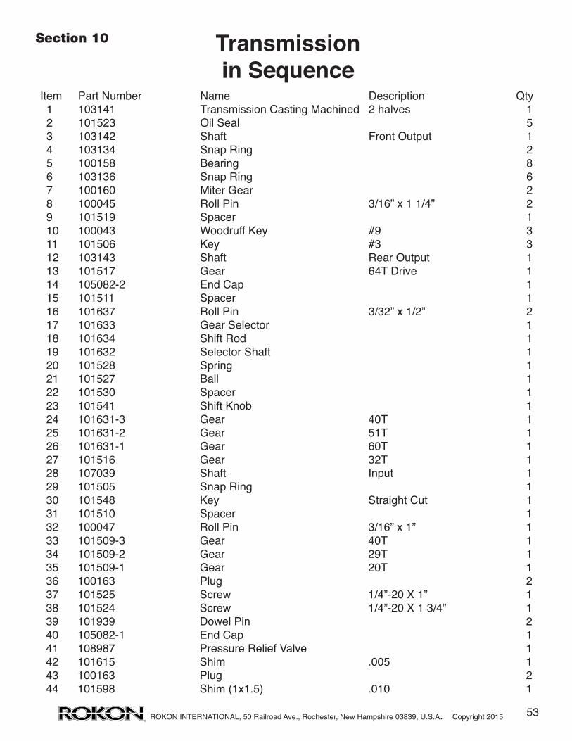
Item Part Number Name Description Qty 1 103141 Transmission Casting Machined 2 halves 1 2 101523 Oil Seal 5 3 103142 Shaft Front Output 1 4 103134 Snap Ring 2 5 100158 Bearing 8 6 103136 Snap Ring 6 7 100160 Miter Gear 2 8 100045 Roll Pin 3/16” x 1 1/4” 2 9 101519 Spacer 1 10 100043 Woodruff Key #9 3 11 101506 Key #3 3 12 103143 Shaft Rear Output 1 13 101517 Gear 64T Drive 1 14 105082-2 End Cap 1 15 101511 Spacer 1 16 101637 Roll Pin 3/32” x 1/2” 2 17 101633 Gear Selector 1 18 101634 Shift Rod 1 19 101632 Selector Shaft 1 20 101528 Spring 1 21 101527 Ball 1 22 101530 Spacer 1 23 101541 Shift Knob 1 24 101631-3 Gear 40T 1 25 101631-2 Gear 51T 1 26 101631-1 Gear 60T 1 27 101516 Gear 32T 1 28 107039 Shaft Input 1 29 101505 Snap Ring 1 30 101548 Key Straight Cut 1 31 101510 Spacer 1 32 100047 Roll Pin 3/16” x 1” 1 33 101509-3 Gear 40T 1 34 101509-2 Gear 29T 1 35 101509-1 Gear 20T 1 36 100163 Plug 2 37 101525 Screw 1/4”-20 X 1” 1 38 101524 Screw 1/4”-20 X 1 3/4” 1 39 101939 Dowel Pin 2 40 105082-1 End Cap 1 41 108987 Pressure Relief Valve 1 42 101615 Shim .005 1 43 100163 Plug 2 44 101598 Shim (1x1.5) .010 1
Transmission in Sequence
Section 10
ROKON INTERNATIONAL, 50 Railroad Ave., Rochester, New Hampshire 03839, U.S.A. Copyright 201554
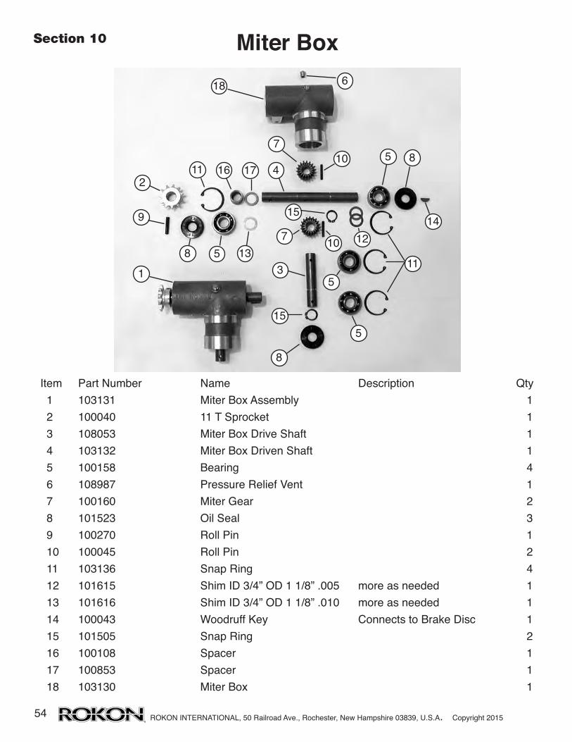
Item Part Number Name Description Qty 1 103131 Miter Box Assembly 1 2 100040 11 T Sprocket 1 3 108053 Miter Box Drive Shaft 1 4 103132 Miter Box Driven Shaft 1 5 100158 Bearing 4 6 108987 Pressure Relief Vent 1 7 100160 Miter Gear 2 8 101523 Oil Seal 3 9 100270 Roll Pin 1 10 100045 Roll Pin 2 11 103136 Snap Ring 4 12 101615 Shim ID 3/4” OD 1 1/8” .005 more as needed 1 13 101616 Shim ID 3/4” OD 1 1/8” .010 more as needed 1 14 100043 Woodruff Key Connects to Brake Disc 1 15 101505 Snap Ring 2 16 100108 Spacer 1 17 100853 Spacer 1 18 103130 Miter Box 1
1
8
15
3 11
9
2
8 5 13
11 16 17 4
710
7 10
15
12
5 8
14
18 6
Miter BoxSection 10
5
5
ROKON INTERNATIONAL, 50 Railroad Ave., Rochester, New Hampshire 03839, U.S.A. Copyright 2015 55
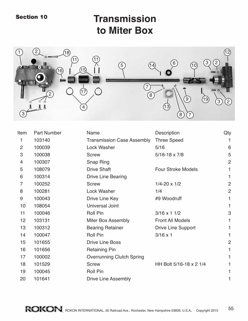
Item Part Number Name Description Qty 1 103140 Transmission Case Assembly Three Speed 1 2 100039 Lock Washer 5/16 6 3 100038 Screw 5/16-18 x 7/8 5 4 100307 Snap Ring 2 5 108079 Drive Shaft Four Stroke Models 1 6 100314 Drive Line Bearing 1 7 100252 Screw 1/4-20 x 1/2 2 8 100281 Lock Washer 1/4 2 9 100043 Drive Line Key #9 Woodruff 1 10 108054 Universal Joint 1 11 100046 Roll Pin 3/16 x 1 1/2 3 12 103131 Miter Box Assembly Front All Models 1 13 100312 Bearing Retainer Drive Line Support 1 14 100047 Roll Pin 3/16 x 1 1 15 101655 Drive Line Boss 2 16 101656 Retaining Pin 1 17 100002 Overrunning Clutch Spring 1 18 101529 Screw HH Bolt 5/16-18 x 2 1/4 1 19 100045 Roll Pin 1 20 101641 Drive Line Assembly 1
Transmission to Miter Box
Section 10
1 2 18
15
11 11
17
3
2
4
5 14 10
12
139 19 3 2
616
3 2
87
8 7
ROKON INTERNATIONAL, 50 Railroad Ave., Rochester, New Hampshire 03839, U.S.A. Copyright 201556
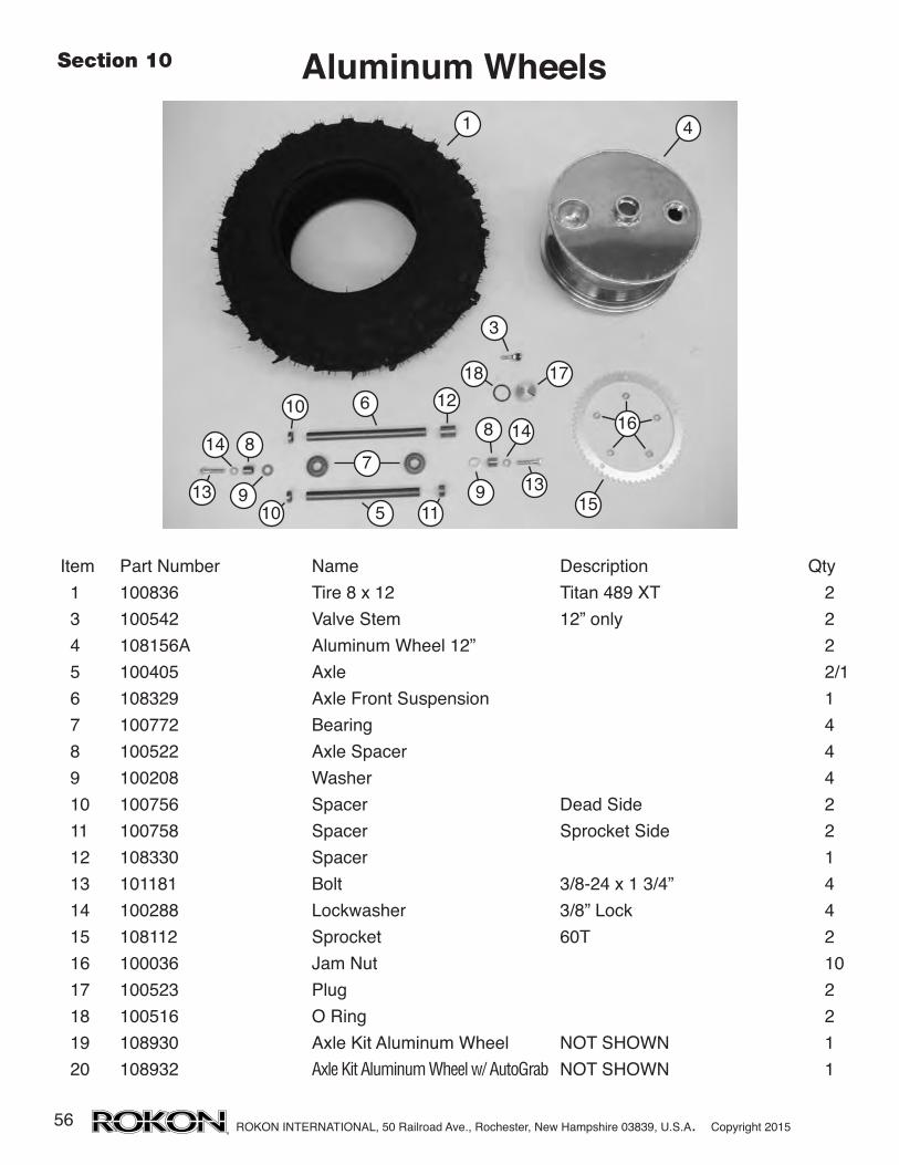
Item Part Number Name Description Qty 1 100836 Tire 8 x 12 Titan 489 XT 2 3 100542 Valve Stem 12” only 2 4 108156A Aluminum Wheel 12” 2 5 100405 Axle 2/1 6 108329 Axle Front Suspension 1 7 100772 Bearing 4 8 100522 Axle Spacer 4 9 100208 Washer 4 10 100756 Spacer Dead Side 2 11 100758 Spacer Sprocket Side 2 12 108330 Spacer 1 13 101181 Bolt 3/8-24 x 1 3/4” 4 14 100288 Lockwasher 3/8” Lock 4 15 108112 Sprocket 60T 2 16 100036 Jam Nut 10 17 100523 Plug 2 18 100516 O Ring 2 19 108930 Axle Kit Aluminum Wheel NOT SHOWN 1 20 108932 Axle Kit Aluminum Wheel w/ AutoGrab NOT SHOWN 1
Aluminum WheelsSection 10
1 4
3
5
7
88
99
610
10 11
12
131513
14
1718
1416
ROKON INTERNATIONAL, 50 Railroad Ave., Rochester, New Hampshire 03839, U.S.A. Copyright 2015 57
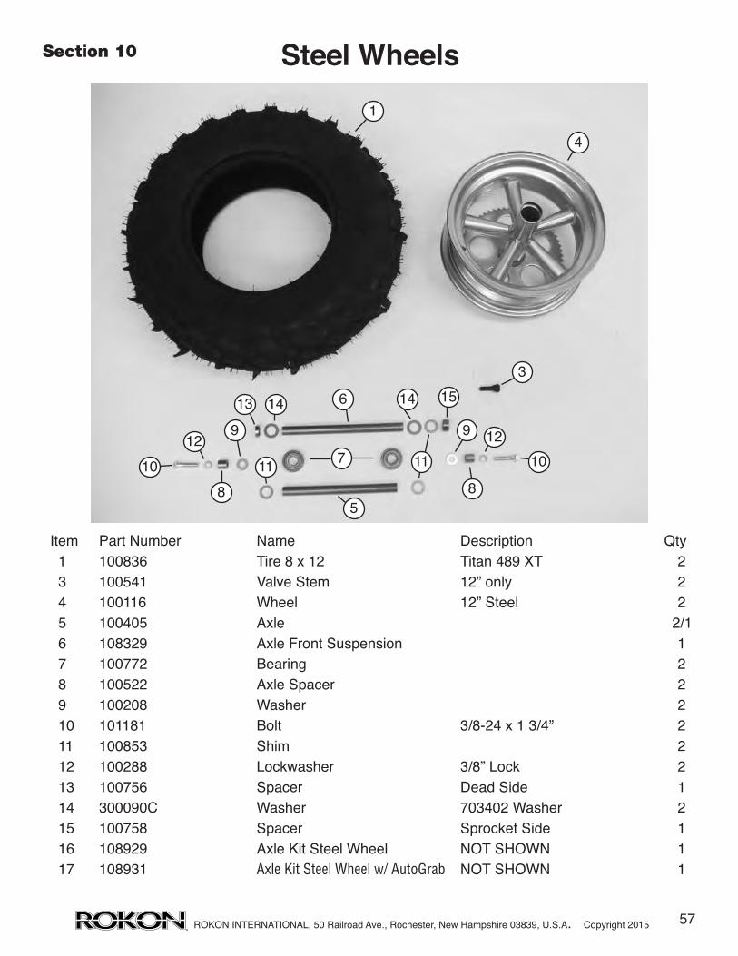
Item Part Number Name Description Qty 1 100836 Tire 8 x 12 Titan 489 XT 2 3 100541 Valve Stem 12” only 2 4 100116 Wheel 12” Steel 2 5 100405 Axle 2/1 6 108329 Axle Front Suspension 1 7 100772 Bearing 2 8 100522 Axle Spacer 2 9 100208 Washer 2 10 101181 Bolt 3/8-24 x 1 3/4” 2 11 100853 Shim 2 12 100288 Lockwasher 3/8” Lock 2 13 100756 Spacer Dead Side 1 14 300090C Washer 703402 Washer 2 15 100758 Spacer Sprocket Side 1 16 108929 Axle Kit Steel Wheel NOT SHOWN 1 17 108931 Axle Kit Steel Wheel w/ AutoGrab NOT SHOWN 1
Steel WheelsSection 10
1010 11
1
3
58 8
99
6
7
4
111212
13 14 14 15
ROKON INTERNATIONAL, 50 Railroad Ave., Rochester, New Hampshire 03839, U.S.A. Copyright 201558
Auto GrabFront Suspension
Section 10
1
2
3
8
4
565
10
15
16
1112
2122
35
36
23
24
2526
22
209
17
18
19 19
20
27
28
29
303132
33
34
ROKON INTERNATIONAL, 50 Railroad Ave., Rochester, New Hampshire 03839, U.S.A. Copyright 2015 59
Auto GrabFront Suspension
Section 10
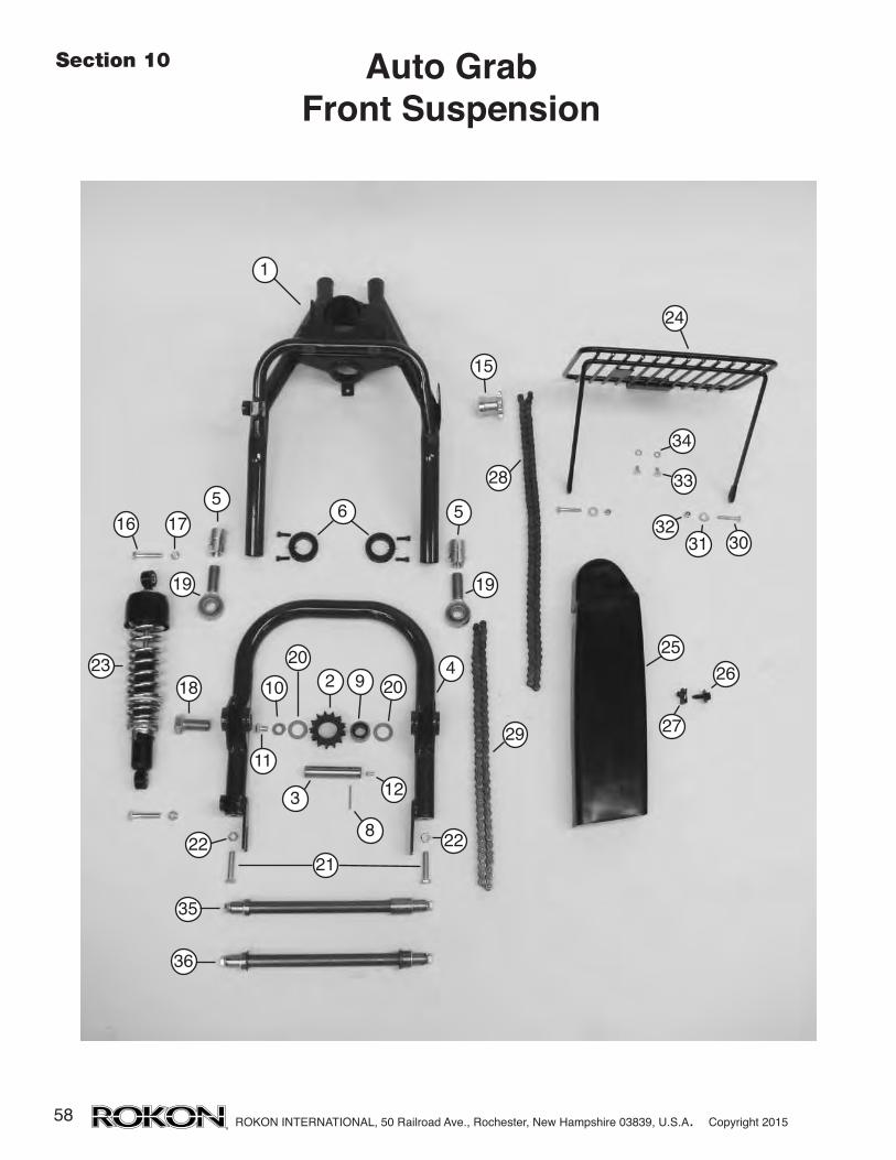
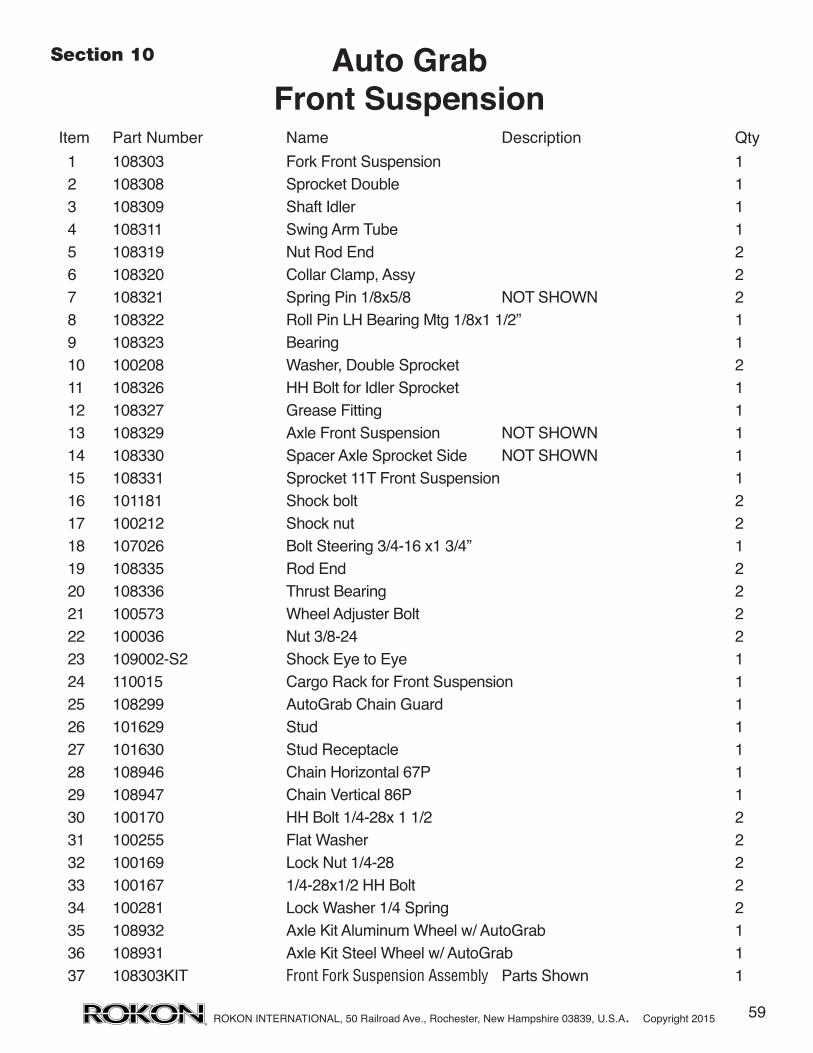
Item Part Number Name Description Qty 1 108303 Fork Front Suspension 1 2 108308 Sprocket Double 1 3 108309 Shaft Idler 1 4 108311 Swing Arm Tube 1 5 108319 Nut Rod End 2 6 108320 Collar Clamp, Assy 2 7 108321 Spring Pin 1/8x5/8 NOT SHOWN 2 8 108322 Roll Pin LH Bearing Mtg 1/8x1 1/2” 1 9 108323 Bearing 1 10 100208 Washer, Double Sprocket 2 11 108326 HH Bolt for Idler Sprocket 1 12 108327 Grease Fitting 1 13 108329 Axle Front Suspension NOT SHOWN 1 14 108330 Spacer Axle Sprocket Side NOT SHOWN 1 15 108331 Sprocket 11T Front Suspension 1 16 101181 Shock bolt 2 17 100212 Shock nut 2 18 107026 Bolt Steering 3/4-16 x1 3/4” 1 19 108335 Rod End 2 20 108336 Thrust Bearing 2 21 100573 Wheel Adjuster Bolt 2 22 100036 Nut 3/8-24 2 23 109002-S2 Shock Eye to Eye 1 24 110015 Cargo Rack for Front Suspension 1 25 108299 AutoGrab Chain Guard 1 26 101629 Stud 1 27 101630 Stud Receptacle 1 28 108946 Chain Horizontal 67P 1 29 108947 Chain Vertical 86P 1 30 100170 HH Bolt 1/4-28x 1 1/2 2 31 100255 Flat Washer 2 32 100169 Lock Nut 1/4-28 2 33 100167 1/4-28x1/2 HH Bolt 2 34 100281 Lock Washer 1/4 Spring 2 35 108932 Axle Kit Aluminum Wheel w/ AutoGrab 1 36 108931 Axle Kit Steel Wheel w/ AutoGrab 1 37 108303KIT Front Fork Suspension Assembly Parts Shown 1
ROKON INTERNATIONAL, 50 Railroad Ave., Rochester, New Hampshire 03839, U.S.A. Copyright 201560
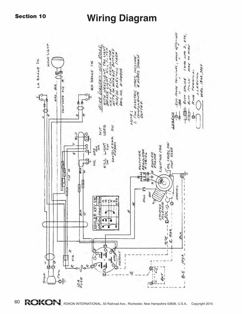
Wiring DiagramSection 10