Embed Size (px)
Citation preview
Configuration & User GuideIllustra Pro Series 5MP, 3MP & 2MP Mini Dome
Series
8200-1135-01 D0
Notice
The information in thismanualwas current when published. Themanufacturer reserves the right to revise and improve itsproducts. All specificationsare therefore subject to change without notice.
Copyright
Under copyright laws, the contents of this manual may not be copied, photocopied, reproduced, translated or reduced to any
electronic medium or machine-readable form, in whole or in part, without prior written consent of Tyco Security Products. ©
2017 Tyco Security Products. All Rights Reserved.
Tyco Security Products
6600 Congress Avenue
Boca Raton, FL 33487 U.S.A.
Customer Service
Thank you for using Illustra products.We support our products through an extensive worldwide network of dealers. Thedealer through whom you originally purchased this product is your point of contact if you need service or support. Our dealersare empowered to provide the very best in customer service and support. Dealers should contact Tyco SecurityProduct s at(800) 507-6268 or (561) 912-6259 or on theWeb at www.illustracameras.com.
Trademarks
Windows® is a registered trademarkof Microsoft Corporation. PS/2® is a registered trademarkof InternationalBusinessMachinesCorporation.
The trademarks, logos, and servicemarksdisplayed on this document are registered in the United States [or other countries].Anymisuse of the trademarks is strictly prohibited and Tyco SecurityProducts. will aggressively enforce its intellectualproperty rights to the fullest extent of the law, including pursuit of criminal prosecution wherever necessary. All trademarksnotowned byTyco SecurityProducts are the property of their respective owners, and are used with permission or allowed underapplicable laws.
Product offeringsand specificationsare subject to change without notice. Actual productsmayvary from photos. Not allproducts include all features. Availability varies by region; contact your sales representative.
License Information
Your use of this product is governed by certain termsand conditions. Please see the detailed license information at the end ofthismanual.
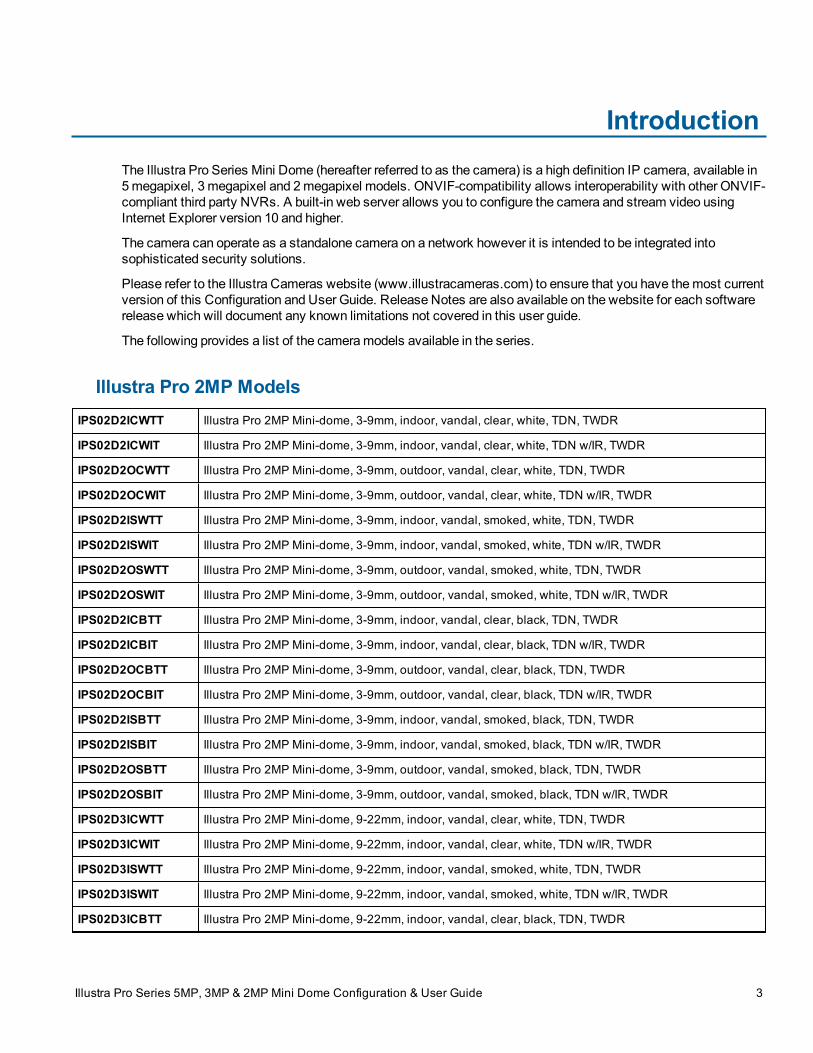
IntroductionThe Illustra Pro Series Mini Dome (hereafter referred to as the camera) is a high definition IP camera, available in5megapixel, 3 megapixel and 2megapixel models. ONVIF-compatibility allows interoperability with other ONVIF-compliant third party NVRs. A built-in web server allows you to configure the camera and stream video usingInternet Explorer version 10 and higher.
The camera can operate as a standalone camera on a network however it is intended to be integrated intosophisticated security solutions.
Please refer to the Illustra Cameras website (www.illustracameras.com) to ensure that you have themost currentversion of this Configuration and User Guide. Release Notes are also available on the website for each softwarerelease which will document any known limitations not covered in this user guide.
The following provides a list of the cameramodels available in the series.
Illustra Pro 2MP ModelsIPS02D2ICWTT Illustra Pro 2MP Mini-dome, 3-9mm, indoor, vandal, clear, white, TDN, TWDR
IPS02D2ICWIT Illustra Pro 2MP Mini-dome, 3-9mm, indoor, vandal, clear, white, TDN w/IR, TWDR
IPS02D2OCWTT Illustra Pro 2MP Mini-dome, 3-9mm, outdoor, vandal, clear, white, TDN, TWDR
IPS02D2OCWIT Illustra Pro 2MP Mini-dome, 3-9mm, outdoor, vandal, clear, white, TDN w/IR, TWDR
IPS02D2ISWTT Illustra Pro 2MP Mini-dome, 3-9mm, indoor, vandal, smoked, white, TDN, TWDR
IPS02D2ISWIT Illustra Pro 2MP Mini-dome, 3-9mm, indoor, vandal, smoked, white, TDN w/IR, TWDR
IPS02D2OSWTT Illustra Pro 2MP Mini-dome, 3-9mm, outdoor, vandal, smoked, white, TDN, TWDR
IPS02D2OSWIT Illustra Pro 2MP Mini-dome, 3-9mm, outdoor, vandal, smoked, white, TDN w/IR, TWDR
IPS02D2ICBTT Illustra Pro 2MP Mini-dome, 3-9mm, indoor, vandal, clear, black, TDN, TWDR
IPS02D2ICBIT Illustra Pro 2MP Mini-dome, 3-9mm, indoor, vandal, clear, black, TDN w/IR, TWDR
IPS02D2OCBTT Illustra Pro 2MP Mini-dome, 3-9mm, outdoor, vandal, clear, black, TDN, TWDR
IPS02D2OCBIT Illustra Pro 2MP Mini-dome, 3-9mm, outdoor, vandal, clear, black, TDN w/IR, TWDR
IPS02D2ISBTT Illustra Pro 2MP Mini-dome, 3-9mm, indoor, vandal, smoked, black, TDN, TWDR
IPS02D2ISBIT Illustra Pro 2MP Mini-dome, 3-9mm, indoor, vandal, smoked, black, TDN w/IR, TWDR
IPS02D2OSBTT Illustra Pro 2MP Mini-dome, 3-9mm, outdoor, vandal, smoked, black, TDN, TWDR
IPS02D2OSBIT Illustra Pro 2MP Mini-dome, 3-9mm, outdoor, vandal, smoked, black, TDN w/IR, TWDR
IPS02D3ICWTT Illustra Pro 2MP Mini-dome, 9-22mm, indoor, vandal, clear, white, TDN, TWDR
IPS02D3ICWIT Illustra Pro 2MP Mini-dome, 9-22mm, indoor, vandal, clear, white, TDN w/IR, TWDR
IPS02D3ISWTT Illustra Pro 2MP Mini-dome, 9-22mm, indoor, vandal, smoked, white, TDN, TWDR
IPS02D3ISWIT Illustra Pro 2MP Mini-dome, 9-22mm, indoor, vandal, smoked, white, TDN w/IR, TWDR
IPS02D3ICBTT Illustra Pro 2MP Mini-dome, 9-22mm, indoor, vandal, clear, black, TDN, TWDR
Illustra Pro Series 5MP, 3MP & 2MP Mini Dome Configuration & User Guide 3
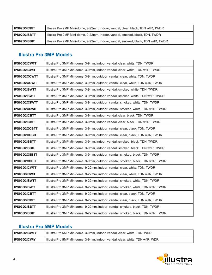
IPS02D3ICBIT Illustra Pro 2MP Mini-dome, 9-22mm, indoor, vandal, clear, black, TDN w/IR, TWDR
IPS02D3ISBTT Illustra Pro 2MP Mini-dome, 9-22mm, indoor, vandal, smoked, black, TDN, TWDR
IPS02D3ISBIT Illustra Pro 2MP Mini-dome, 9-22mm, indoor, vandal, smoked, black, TDN w/IR, TWDR
Illustra Pro 3MP ModelsIPS03D2ICWTT Illustra Pro 3MP Minidome, 3-9mm, indoor, vandal, clear, white, TDN, TWDR
IPS03D2ICWIT Illustra Pro 3MP Minidome, 3-9mm, indoor, vandal, clear, white, TDN w/IR, TWDR
IPS03D2OCWTT Illustra Pro 3MP Minidome, 3-9mm, outdoor, vandal, clear, white, TDN, TWDR
IPS03D2OCWIT Illustra Pro 3MP Minidome, 3-9mm, outdoor, vandal, clear, white, TDN w/IR, TWDR
IPS03D2ISWTT Illustra Pro 3MP Minidome, 3-9mm, indoor, vandal, smoked, white, TDN, TWDR
IPS03D2ISWIT Illustra Pro 3MP Minidome, 3-9mm, indoor, vandal, smoked, white, TDN w/IR, TWDR
IPS03D2OSWTT Illustra Pro 3MP Minidome, 3-9mm, outdoor, vandal, smoked, white, TDN, TWDR
IPS03D2OSWIT Illustra Pro 3MP Minidome, 3-9mm, outdoor, vandal, smoked, white, TDN w/IR, TWDR
IPS03D2ICBTT Illustra Pro 3MP Minidome, 3-9mm, indoor, vandal, clear, black, TDN, TWDR
IPS03D2ICBIT Illustra Pro 3MP Minidome, 3-9mm, indoor, vandal, clear, black, TDN w/IR, TWDR
IPS03D2OCBTT Illustra Pro 3MP Minidome, 3-9mm, outdoor, vandal, clear, black, TDN, TWDR
IPS03D2OCBIT Illustra Pro 3MP Minidome, 3-9mm, outdoor, vandal, clear, black, TDN w/IR, TWDR
IPS03D2ISBTT Illustra Pro 3MP Minidome, 3-9mm, indoor, vandal, smoked, black, TDN, TWDR
IPS03D2ISBIT Illustra Pro 3MP Minidome, 3-9mm, indoor, vandal, smoked, black, TDN w/IR, TWDR
IPS03D2OSBTT Illustra Pro 3MP Minidome, 3-9mm, outdoor, vandal, smoked, black, TDN, TWDR
IPS03D2OSBIT Illustra Pro 3MP Minidome, 3-9mm, outdoor, vandal, smoked, black, TDN w/IR, TWDR
IPS03D3ICWTT Illustra Pro 3MP Minidome, 9-22mm, indoor, vandal, clear, white, TDN, TWDR
IPS03D3ICWIT Illustra Pro 3MP Minidome, 9-22mm, indoor, vandal, clear, white, TDN w/IR, TWDR
IPS03D3ISWTT Illustra Pro 3MP Minidome, 9-22mm, indoor, vandal, smoked, white, TDN, TWDR
IPS03D3ISWIT Illustra Pro 3MP Minidome, 9-22mm, indoor, vandal, smoked, white, TDN w/IR, TWDR
IPS03D3ICBTT Illustra Pro 3MP Minidome, 9-22mm, indoor, vandal, clear, black, TDN, TWDR
IPS03D3ICBIT Illustra Pro 3MP Minidome, 9-22mm, indoor, vandal, clear, black, TDN w/IR, TWDR
IPS03D3ISBTT Illustra Pro 3MP Minidome, 9-22mm, indoor, vandal, smoked, black, TDN, TWDR
IPS03D3ISBIT Illustra Pro 3MP Minidome, 9-22mm, indoor, vandal, smoked, black, TDN w/IR, TWDR
Illustra Pro 5MP ModelsIPS05D2ICWTY Illustra Pro 5MP Minidome, 3-9mm, indoor, vandal, clear, white, TDN, WDR
IPS05D2ICWIY Illustra Pro 5MP Minidome, 3-9mm, indoor, vandal, clear, white, TDN w/IR, WDR
4
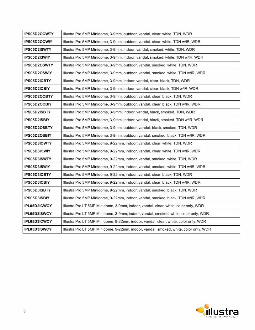
IPS05D2OCWTY Illustra Pro 5MP Minidome, 3-9mm, outdoor, vandal, clear, white, TDN, WDR
IPS05D2OCWIY Illustra Pro 5MP Minidome, 3-9mm, outdoor, vandal, clear, white, TDN w/IR, WDR
IPS05D2ISWTY Illustra Pro 5MP Minidome, 3-9mm, indoor, vandal, smoked, white, TDN, WDR
IPS05D2ISWIY Illustra Pro 5MP Minidome, 3-9mm, indoor, vandal, smoked, white, TDN w/IR, WDR
IPS05D2OSWTY Illustra Pro 5MP Minidome, 3-9mm, outdoor, vandal, smoked, white, TDN, WDR
IPS05D2OSWIY Illustra Pro 5MP Minidome, 3-9mm, outdoor, vandal, smoked, white, TDN w/IR, WDR
IPS05D2ICBTY Illustra Pro 5MP Minidome, 3-9mm, indoor, vandal, clear, black, TDN, WDR
IPS05D2ICBIY Illustra Pro 5MP Minidome, 3-9mm, indoor, vandal, clear, black, TDN w/IR, WDR
IPS05D2OCBTY Illustra Pro 5MP Minidome, 3-9mm, outdoor, vandal, clear, black, TDN, WDR
IPS05D2OCBIY Illustra Pro 5MP Minidome, 3-9mm, outdoor, vandal, clear, black, TDN w/IR, WDR
IPS05D2ISBTY Illustra Pro 5MP Minidome, 3-9mm, indoor, vandal, black, smoked, TDN, WDR
IPS05D2ISBIY Illustra Pro 5MP Minidome, 3-9mm, indoor, vandal, black, smoked, TDN w/IR, WDR
IPS05D2OSBTY Illustra Pro 5MP Minidome, 3-9mm, outdoor, vandal, black, smoked, TDN, WDR
IPS05D2OSBIY Illustra Pro 5MP Minidome, 3-9mm, outdoor, vandal, smoked, black, TDN w/IR, WDR
IPS05D3ICWTY Illustra Pro 5MP Minidome, 9-22mm, indoor, vandal, clear, white, TDN, WDR
IPS05D3ICWIY Illustra Pro 5MP Minidome, 9-22mm, indoor, vandal, clear, white, TDN w/IR, WDR
IPS05D3ISWTY Illustra Pro 5MP Minidome, 9-22mm, indoor, vandal, smoked, white, TDN, WDR
IPS05D3ISWIY Illustra Pro 5MP Minidome, 9-22mm, indoor, vandal, smoked, white, TDN w/IR, WDR
IPS05D3ICBTY Illustra Pro 5MP Minidome, 9-22mm, indoor, vandal, clear, black, TDN, WDR
IPS05D3ICBIY Illustra Pro 5MP Minidome, 9-22mm, indoor, vandal, clear, black, TDN w/IR, WDR
IPS05D3ISBTY Illustra Pro 5MP Minidome, 9-22mm, indoor, vandal, smoked, black, TDN, WDR
IPS05D3ISBIY Illustra Pro 5MP Minidome, 9-22mm, indoor, vandal, smoked, black, TDN w/IR, WDR
IPL05D2ICWCY Illustra Pro LT 5MP Minidome, 3-9mm, indoor, vandal, clear, white, color only, WDR
IPL05D2ISWCY Illustra Pro LT 5MP Minidome, 3-9mm, indoor, vandal, smoked, white, color only, WDR
IPL05D3ICWCY Illustra Pro LT 5MP Minidome, 9-22mm, indoor, vandal, clear, white, color only, WDR
IPL05D3ISWCY Illustra Pro LT 5MP Minidome, 9-22mm, indoor, vandal, smoked, white, color only, WDR
5
Web ConfigurationThis section details how to configure the camera using the built-inWebConfiguration feature.
Note:
1 Adobe Reader must be installed to view the online help.
2 To view the video pane at the cameras best quality the latest version of QuickTimemust be installed andenabled on the computer running the browser session, this will allow for a supported stream on thecamera to be viewed on theWebUser Interface. Otherwise the camera will use a lower bandwidthstream to display live video on theWebUser Interface.
3 WebConfiguration sessions timeout after a period of inactivity.
4 Only users with administrative rights can access all the areas of theWebConfiguration pages.
Security Mode Profiles for First Time ConnectionThe Illustra Pro Series Mini Dome camera now has Enhanced Security features that allow for operation in a Standard Security mode or in an Enhanced Security mode.
The Enhanced Security mode of operation is used to control changes to the camera communication protocolsHTTP, HTTPS, FTP, and SMTP. When the camera is in Enhanced Security mode, a complex seven characterAdministrator password is required tomake changes to these protocols.
Accessing the Illustra Pro Series Camera Web User Interface
Logging in to the CameraUse the following procedure to access the cameraWebUser Interface.
Procedure 2-1 Log in to the Camera
Step Action
1 Refer to the Installation chapter for details on how to connect the camera to your network or computer.
2 When the camera is selected the sign in page will be displayed.
3 Select your preferred language from the drop-downmenu.
The default language is ‘English’.
4 Enter the default ID and password when prompted - ID: admin, Password: admin.Note:
Security Profile:The first time you access the camera, you are prompted to use either the Standard Security or EnhancedSecurity. If you are keeping Standard Security, best practice is to use the Change Password check boxto immediately change the default password to one unique to your surveillance system.
Illustra Pro Series 5MP, 3MP & 2MP Mini Dome Configuration & User Guide 6
Changing the Camera Web User Interface Language
5 If you select the Enhanced Security option, you will be required and instructed to create a complexpassword.Note:
The passwordmust meet the following requirements:
• Be aminimum of seven characters long.
• Have at least one character from at least three of the following character groups:
• Upper-case letters
• Lower-case letters
• Numeric characters
• Special characters
6 Click Log in.The cameraWebUser Interface displays.
- End -
Logging out of the CameraUse the following procedure to log off the cameraWebUser Interface.
Procedure 2-2 Log off the Camera
Step Action
1 Select LogOff in the upper right hand corner of theWebUser Interface.
You will be logged off the camera and sign in page will be displayed.
- End -
Changing the Camera Web User Interface LanguageUse the following procedure to change the language used in the cameraWebUser Interface.
Procedure 2-3 Change the Camera Web User Interface Language
Step Action
1 Open the camera sign in page. If you are already logged in to theWebUser Interface, select LogOff todisplay the sign in page.
2 Select your preferred language from the drop-downmenu:
• English• Arabic• Czech
7
Accessing the Setup Menus from Live View
• Danish• German• Spanish• French• Hungarian• Italian• Japanese• Korean• Dutch• Polish• Portuguese• Swedish• Turkish• Chinese Simplified• Chinese TraditionalThe default language is ‘English’.
3 Enter theUsername.4 Enter thePassword.5 Select Log in.
The camera web User Interface will be displayed in the selected language.
- End -
Accessing the Setup Menus from Live ViewSetupmenus within the web User Interface are restricted by user account access levels.
Refer to Appendix A: User Account Access for details on the features which are available to each role.
Procedure 2-4 Access Setup Menus from Live View
Step Action
1 When displaying full screen live video select Setup on theWebUser Interface banner to access thesetupmenus.
TheModel page will be displayed.Note:
When an admin user logs in for the first time theQuick Start page will be displayed. After this, on eachlogin the Stream page will be displayed.
8
Displaying the Live View Page
Displaying the Live View PageDisplay the live camera view page.
Procedure 2-5 Display Live View Page
Step Action
1 Select Live in theWebUser Interface banner.
The live view page will be displayed.
2 Select a video stream from Stream to view.
3 Select a percentage from Scale to change the display size of the video pane:• 25%• 50%• 75%• 100%The default setting is ‘50%’
- End -
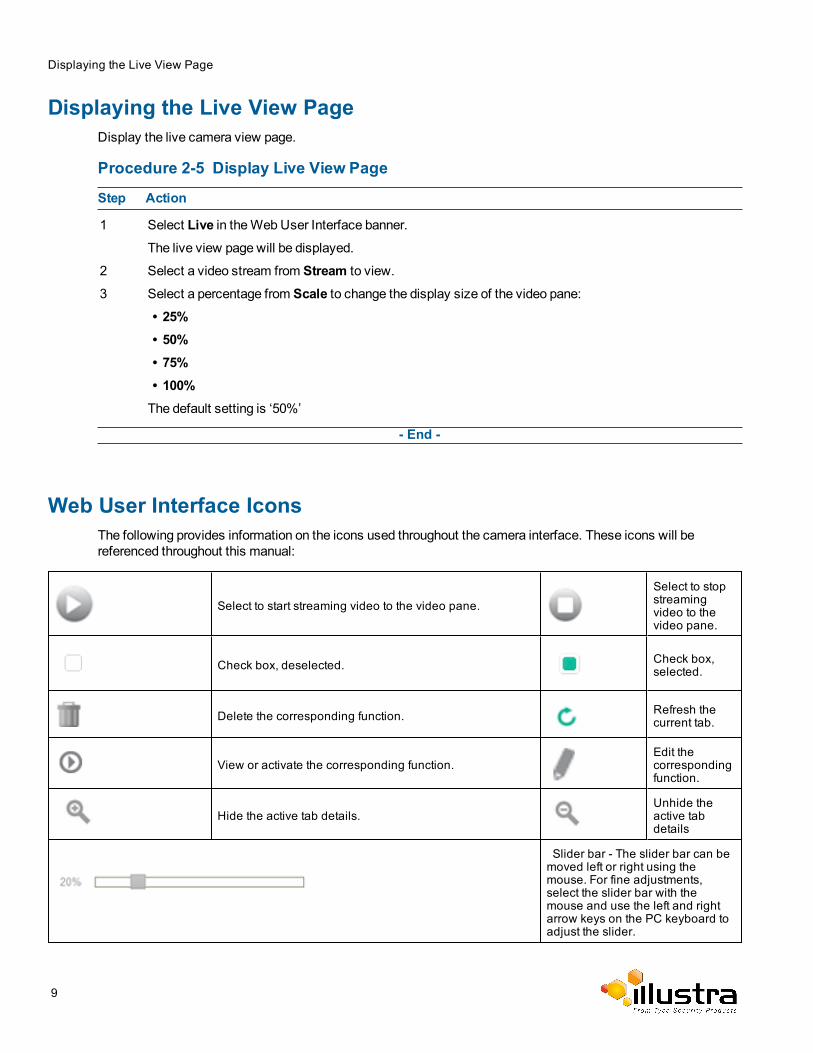
Web User Interface IconsThe following provides information on the icons used throughout the camera interface. These icons will bereferenced throughout this manual:
Select to start streaming video to the video pane.Select to stopstreamingvideo to thevideo pane.
Check box, deselected. Check box,selected.
Delete the corresponding function. Refresh thecurrent tab.
View or activate the corresponding function.Edit thecorrespondingfunction.
Hide the active tab details.Unhide theactive tabdetails
Slider bar - The slider bar can bemoved left or right using themouse. For fine adjustments,select the slider bar with themouse and use the left and rightarrow keys on the PC keyboard toadjust the slider.
9
Video Pane
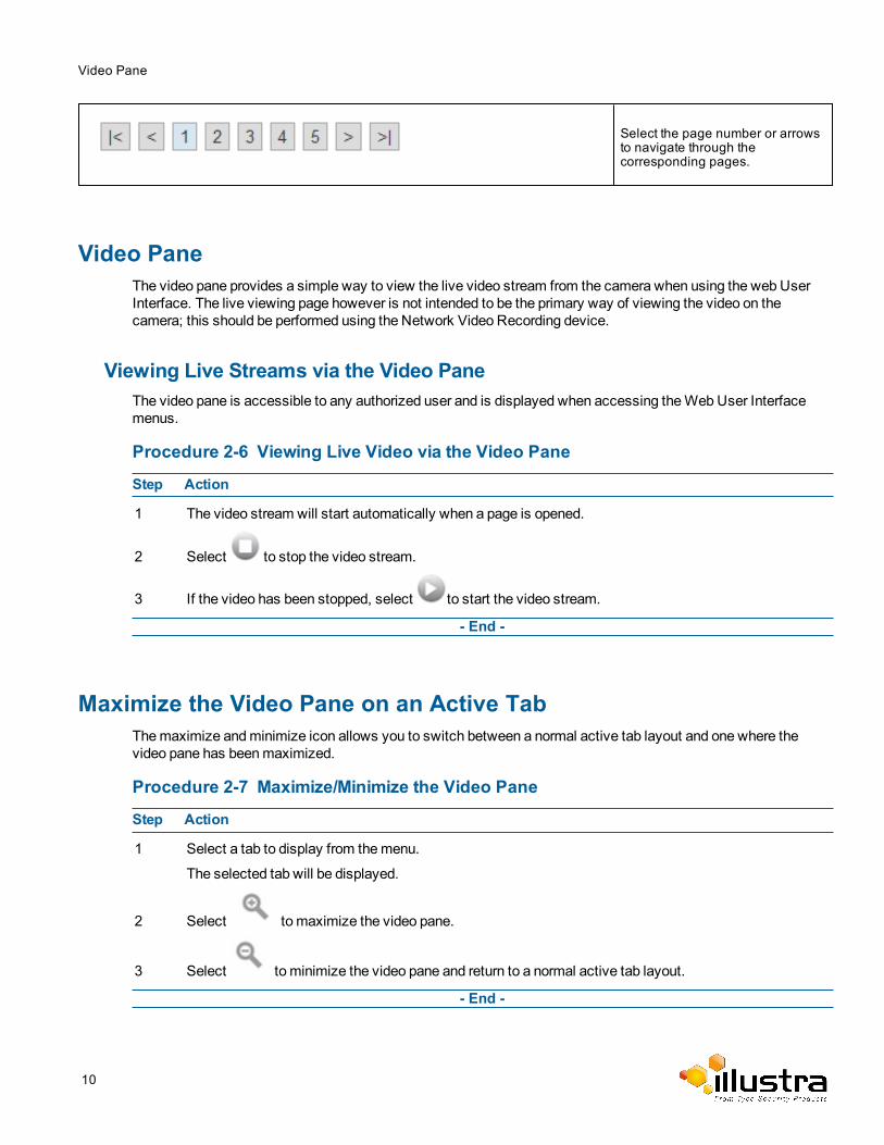
Select the page number or arrowsto navigate through thecorresponding pages.
Video PaneThe video pane provides a simple way to view the live video stream from the camera when using the web UserInterface. The live viewing page however is not intended to be the primary way of viewing the video on thecamera; this should be performed using the Network Video Recording device.
Viewing Live Streams via the Video PaneThe video pane is accessible to any authorized user and is displayed when accessing theWebUser Interfacemenus.
Procedure 2-6 Viewing Live Video via the Video Pane
Step Action
1 The video stream will start automatically when a page is opened.
2 Select to stop the video stream.
3 If the video has been stopped, select to start the video stream.
- End -
Maximize the Video Pane on an Active TabThemaximize andminimize icon allows you to switch between a normal active tab layout and one where thevideo pane has beenmaximized.
Procedure 2-7 Maximize/Minimize the Video Pane
Step Action
1 Select a tab to display from themenu.
The selected tab will be displayed.
2 Select to maximize the video pane.
3 Select to minimize the video pane and return to a normal active tab layout.
- End -
10
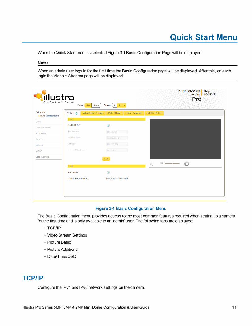
Quick Start MenuWhen theQuick Start menu is selected Figure 3-1 Basic Configuration Page will be displayed.
Note:
When an admin user logs in for the first time the Basic Configuration page will be displayed. After this, on eachlogin the Video > Streams page will be displayed.
Figure 3-1 Basic Configuration Menu
The Basic Configurationmenu provides access to themost common features required when setting up a camerafor the first time and is only available to an ‘admin’ user. The following tabs are displayed:
• TCP/IP
• Video Stream Settings
• Picture Basic
• Picture Additional
• Date/Time/OSD
TCP/IPConfigure the IPv4 and IPv6 network settings on the camera.
Illustra Pro Series 5MP, 3MP & 2MP Mini Dome Configuration & User Guide 11
TCP/IP
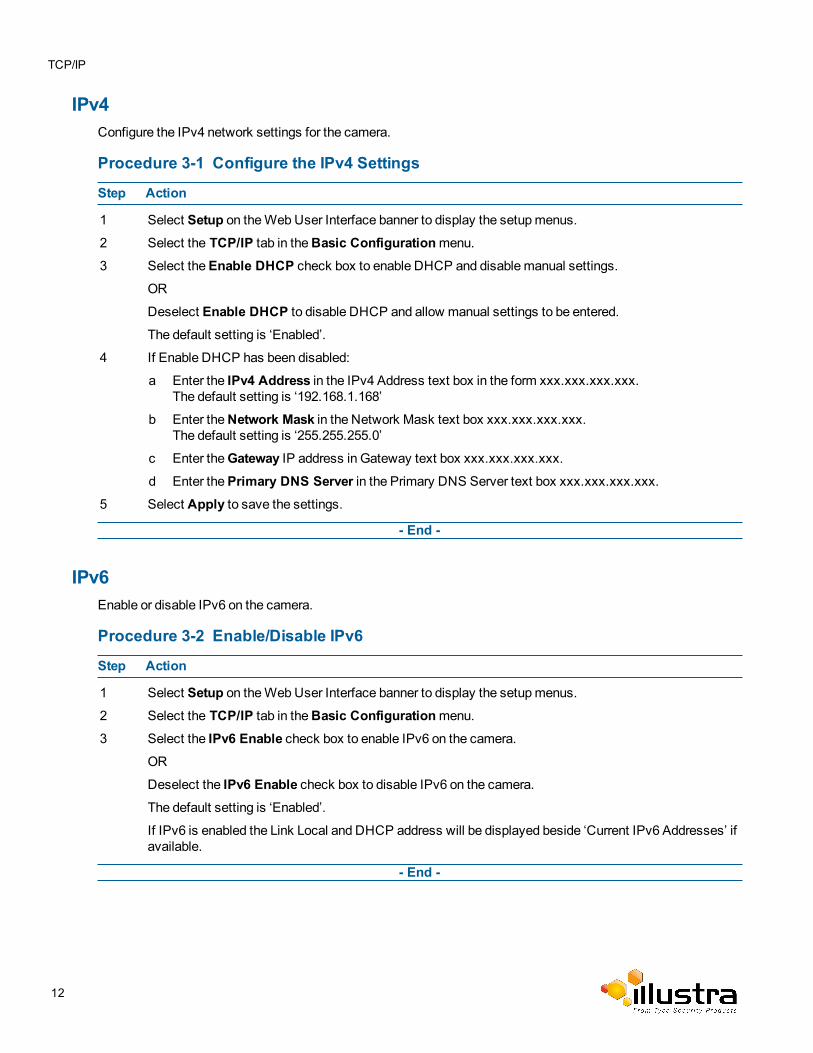
IPv4Configure the IPv4 network settings for the camera.
Procedure 3-1 Configure the IPv4 Settings
Step Action
1 Select Setup on theWebUser Interface banner to display the setupmenus.
2 Select the TCP/IP tab in theBasic Configurationmenu.3 Select theEnable DHCP check box to enable DHCP and disable manual settings.
OR
Deselect Enable DHCP to disable DHCP and allow manual settings to be entered.
The default setting is ‘Enabled’.
4 If Enable DHCP has been disabled:
a Enter the IPv4 Address in the IPv4 Address text box in the form xxx.xxx.xxx.xxx.The default setting is ‘192.168.1.168’
b Enter theNetwork Mask in the Network Mask text box xxx.xxx.xxx.xxx.The default setting is ‘255.255.255.0’
c Enter theGateway IP address in Gateway text box xxx.xxx.xxx.xxx.
d Enter thePrimary DNS Server in the Primary DNS Server text box xxx.xxx.xxx.xxx.
5 Select Apply to save the settings.
- End -
IPv6Enable or disable IPv6 on the camera.
Procedure 3-2 Enable/Disable IPv6
Step Action
1 Select Setup on theWebUser Interface banner to display the setupmenus.
2 Select the TCP/IP tab in theBasic Configurationmenu.3 Select the IPv6 Enable check box to enable IPv6 on the camera.
OR
Deselect the IPv6 Enable check box to disable IPv6 on the camera.The default setting is ‘Enabled’.
If IPv6 is enabled the Link Local and DHCP address will be displayed beside ‘Current IPv6 Addresses’ ifavailable.
- End -
12
Video Stream Settings
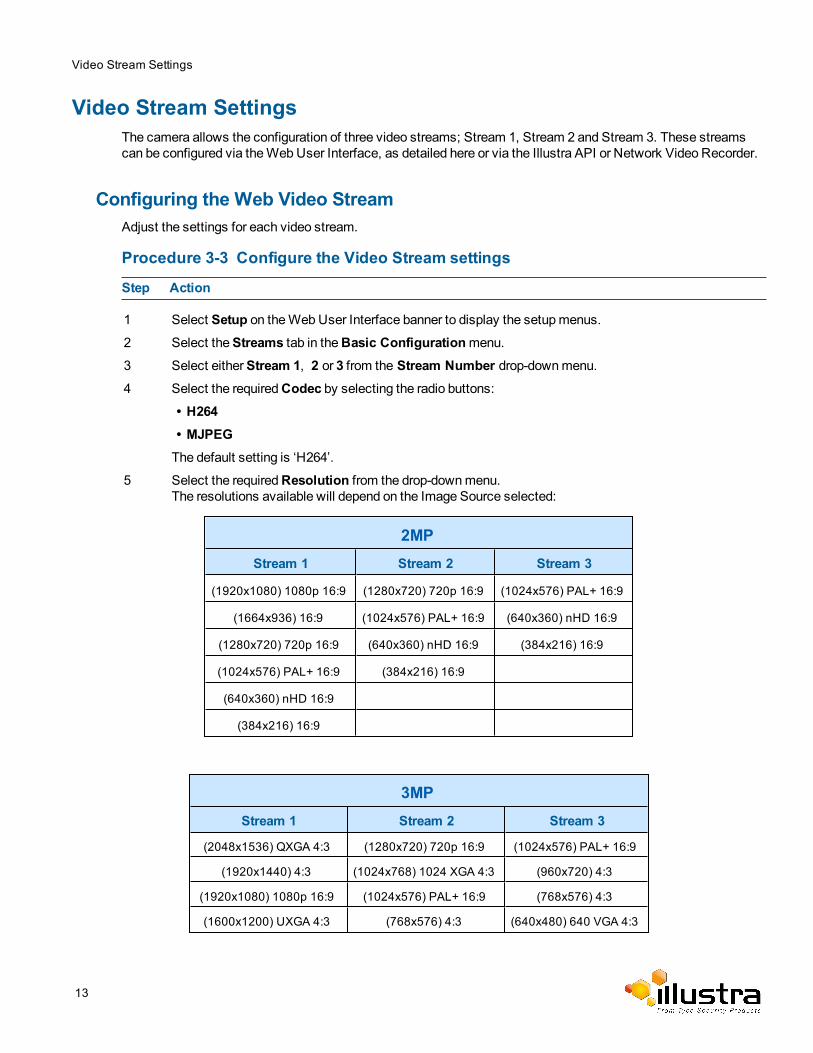
Video Stream SettingsThe camera allows the configuration of three video streams; Stream 1, Stream 2 and Stream 3. These streamscan be configured via theWebUser Interface, as detailed here or via the Illustra API or Network Video Recorder.
Configuring the Web Video StreamAdjust the settings for each video stream.
Procedure 3-3 Configure the Video Stream settings
Step Action
1 Select Setup on theWebUser Interface banner to display the setupmenus.
2 Select theStreams tab in theBasic Configurationmenu.3 Select eitherStream 1, 2 or 3 from the Stream Number drop-downmenu.4 Select the requiredCodec by selecting the radio buttons:
• H264• MJPEGThe default setting is ‘H264’.
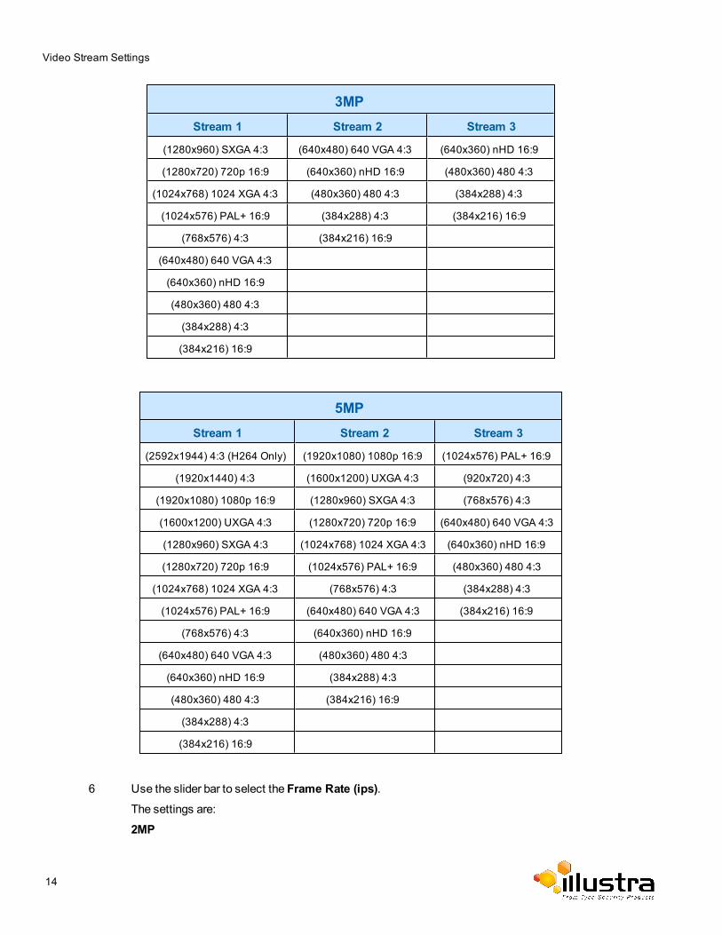
5 Select the requiredResolution from the drop-downmenu.The resolutions available will depend on the Image Source selected:
2MPStream 1 Stream 2 Stream 3
(1920x1080) 1080p 16:9 (1280x720) 720p 16:9 (1024x576) PAL+ 16:9
(1664x936) 16:9 (1024x576) PAL+ 16:9 (640x360) nHD 16:9
(1280x720) 720p 16:9 (640x360) nHD 16:9 (384x216) 16:9
(1024x576) PAL+ 16:9 (384x216) 16:9
(640x360) nHD 16:9
(384x216) 16:9
3MPStream 1 Stream 2 Stream 3
(2048x1536) QXGA 4:3 (1280x720) 720p 16:9 (1024x576) PAL+ 16:9
(1920x1440) 4:3 (1024x768) 1024 XGA 4:3 (960x720) 4:3
(1920x1080) 1080p 16:9 (1024x576) PAL+ 16:9 (768x576) 4:3
(1600x1200) UXGA 4:3 (768x576) 4:3 (640x480) 640 VGA 4:3
13
Video Stream Settings
3MPStream 1 Stream 2 Stream 3
(1280x960) SXGA 4:3 (640x480) 640 VGA 4:3 (640x360) nHD 16:9
(1280x720) 720p 16:9 (640x360) nHD 16:9 (480x360) 480 4:3
(1024x768) 1024 XGA 4:3 (480x360) 480 4:3 (384x288) 4:3
(1024x576) PAL+ 16:9 (384x288) 4:3 (384x216) 16:9
(768x576) 4:3 (384x216) 16:9
(640x480) 640 VGA 4:3
(640x360) nHD 16:9
(480x360) 480 4:3
(384x288) 4:3
(384x216) 16:9
5MPStream 1 Stream 2 Stream 3
(2592x1944) 4:3 (H264 Only) (1920x1080) 1080p 16:9 (1024x576) PAL+ 16:9
(1920x1440) 4:3 (1600x1200) UXGA 4:3 (920x720) 4:3
(1920x1080) 1080p 16:9 (1280x960) SXGA 4:3 (768x576) 4:3
(1600x1200) UXGA 4:3 (1280x720) 720p 16:9 (640x480) 640 VGA 4:3
(1280x960) SXGA 4:3 (1024x768) 1024 XGA 4:3 (640x360) nHD 16:9
(1280x720) 720p 16:9 (1024x576) PAL+ 16:9 (480x360) 480 4:3
(1024x768) 1024 XGA 4:3 (768x576) 4:3 (384x288) 4:3
(1024x576) PAL+ 16:9 (640x480) 640 VGA 4:3 (384x216) 16:9
(768x576) 4:3 (640x360) nHD 16:9
(640x480) 640 VGA 4:3 (480x360) 480 4:3
(640x360) nHD 16:9 (384x288) 4:3
(480x360) 480 4:3 (384x216) 16:9
(384x288) 4:3
(384x216) 16:9
6 Use the slider bar to select the Frame Rate (ips).The settings are:
2MP
14
Video Stream Settings
• Stream 1 - 1 - 30 ips, default 30.• Stream 2 - 1 - 15 ips, default 15.• Stream 3 - 7ips fixed.
3MP• Stream 1 - 1 - 30 ips, default 30.• Stream 2 - 1 - 15 ips, default 15.• Stream 3 - 7ips fixed.
5MP• Stream 1 - 1 - 15 ips, default 15.• Stream 2 - 1 - 15 ips, default 15.• Stream 3 - 7ips fixed.
7 If MJPEG has been selected, MJPEGQuality will be enabled. Use the slider bar to select theMJPEGQuality.The default setting is 50.
OR
8 If H264 has been selected in step 4, Rate Control will be enabled. Select the requiredRate Control byselecting the radio buttons:
• VBR (Variable Bit Rate)• CBR (Constant Bit Rate)The default setting is ‘VBR’.
a If VBR has been selected, VBR Quality will be enabled. Select the requiredVBR Quality from thedrop-downmenu.
• Highest
• High
• Medium
• Low
• Lowest
The default setting is ‘High’.
OR
b If CBR has been selected, CBR Bit Rate will be enabled. Use the slider bar to select theCBR BitRate.
The default setting is 1000.
9 Select theEnable Gaming Mode checkbox to enable gamingmodeOR
De-select theEnable Gaming Mode checkbox to disable gamingmode.The default setting is 'Disabled'. Refer to Quick Start Menu
15
Gaming Mode
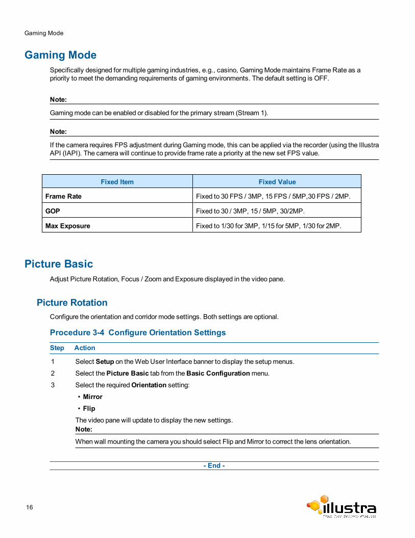
Gaming ModeSpecifically designed for multiple gaming industries, e.g., casino, GamingModemaintains FrameRate as apriority to meet the demanding requirements of gaming environments. The default setting is OFF.
Note:
Gamingmode can be enabled or disabled for the primary stream (Stream 1).
Note:
If the camera requires FPS adjustment during Gamingmode, this can be applied via the recorder (using the IllustraAPI (IAPI). The camera will continue to provide frame rate a priority at the new set FPS value.
Fixed Item Fixed Value
Frame Rate Fixed to 30 FPS / 3MP, 15 FPS / 5MP,30 FPS / 2MP.
GOP Fixed to 30 / 3MP, 15 / 5MP, 30/2MP.
Max Exposure Fixed to 1/30 for 3MP, 1/15 for 5MP, 1/30 for 2MP.
Picture BasicAdjust Picture Rotation, Focus / Zoom and Exposure displayed in the video pane.
Picture RotationConfigure the orientation and corridor mode settings. Both settings are optional.
Procedure 3-4 Configure Orientation Settings
Step Action
1 Select Setup on theWebUser Interface banner to display the setupmenus.
2 Select thePicture Basic tab from theBasic Configurationmenu.3 Select the requiredOrientation setting:
• Mirror• FlipThe video pane will update to display the new settings.Note:
Whenwall mounting the camera you should select Flip andMirror to correct the lens orientation.
- End -
16
Picture Basic
Corridor ModeProvides a better perspective when viewing a long corridor.
Note:
This feature is only available on the 2MP cameramodels.
Procedure 3-5 Configure Corridor Mode Settings
Step Action
1 Select Setup on theWebUser Interface banner to display the setupmenus.
2 Select the Picture Basic tab from the Basic Configurationmenu.
3 Select to start the video stream if it is not already active.
4 Select the required Corridor Mode setting:
• None
• -90°
• +90°
The video pane will update to display the new settings.
- End -
Focus / ZoomThe Focus is manually configured on initial setup. TheOne Touch button can be used to automatically focus thearea of view highlighted in the yellow outlined box displayed on the video pane. This box can bemoved andresized as required and subsequent manual adjustments can be applied if required using the plus andminusvalues. The plus andminus arrows are used tomanually fine tune the image.
The Zoom slider bar is used tomanually zoom in and out to manually configure to picture.
When IR Compensate is enabled, the camera refocuses within 30 seconds of themode transisition between dayto night mode and night to day mode.
Procedure 3-6 Adjust Camera Focus / Zoom
Step Action
1 Select Setup on theWebUser Interface banner to display the setupmenus.
2 Select thePicture Basic tab from theBasic Configurationmenu.
3 Select to start the video stream if it is not already active.
4 Use the plus andminus arrows tomanually configure the focus and the slider bar to adjust zoom settingsuntil the image is clear.
The video pane will update to display the new settings.
- End -
17
Picture Basic
Procedure 3-7 Adjust Camera Focus using OneTouch Autofocus
1 Select Setup on theWebUser Interface banner to display the setupmenus.
2 Select thePicture Basic tab from theBasic Configurationmenu.
3 Select to start the video stream if it is not already active.
4 Draw a region around the area to be focused on within the image.
5 Select theOne Touch button.The camera refocuses to the optimal zoom level for the image.
The video pane will update to display the new settings.
- End -
Procedure 3-8 Enable/Disable IR Compensate
1 Select Setup on theWebUser Interface banner to display the setupmenus.
2 Select thePicture Basic tab from theBasic Configurationmenu.3 Select the IR compensate check box to enable IR compensation
OR
Clear the IR compensate check box to disable IR compensation.
- End -
ExposureConfigure the exposure settings for the camera.
Procedure 3-9 Configure Exposure Settings
Step Action
1 Select Setup on theWebUser Interface banner to display the setupmenus.
2 Select thePicture Settings tab from theBasic Configurationmenu.
3 Select to start the video stream if it is not already active.
4 Select theExposure Method from the drop-downmenu:
• Full Picture Weighted - exposure calculations are based on the entire image.• Center Weighted - exposure calculations are based on a region around the center of theimage.
• Spot - exposure calculations are based on the very center of the image.• ROI Weighted - exposure calculations are based on a region of interest selected.The default setting is CenterWeighted.
5 Select theExposure Offset (F-Stops) from the drop-downmenu.
18
Picture Additional
The default setting is 0.0.
6 Select theMax Exposure from the drop-downmenu.
The default setting is 1/4 for 5MP, 1/8 for 3MP and 1/8 for 2MP.
7 Select theMax Gain from the drop-downmenu.The default setting is 30db for 5MP, 42db for 3MP and 42db for 2MP.The video pane will update to display the new settings.
8 Select theBright objects from the drop-downmenu.The default setting is auto.
9 Select the Flicker control from the drop-downmenu.
50 Hz= max 25 fps
60Hz = max 30 fps
The default setting is 60HZ.
- End -
Procedure 3-10 Restore Exposure Defaults
Step Action
1 Select Setup on theWebUser Interface banner to display the setupmenus.
2 Select thePicture Settings tab from theBasic Configurationmenu.
3 Select to start the video stream if it is not already active.
4 Select Exposure Defaults to restore the default settings.The default values are:
• ExposureMethod: CenterWeighted
• Exposure Offset (F-Stops): 0
• Max Exposure (sec): 1/30 for 5MP, 1/8 for 3MP and 1/8 for 2MP
• Max Gain (dB): 30db for 5MP, 42db for 3MP and 42db for 2MP
• Bright objects: auto
• Flicker control (Hertz): 60HZ
- End -
Picture AdditionalConfigureWide Dynamic Range, Day Night Mode, Flicker Control and Picture Adjustments including Brightness,Contrast, White Balance, Saturation and Sharpness displayed in the video pane.
Wide Dynamic RangeWide Dynamic Range (WDR) is a feature that allows viewing of high contrast scenes that include both bright andlow light areas in the same field of view (FOV).
19
Picture Additional
WDR Level allows you to adjust theWDR level to favour a underexposed or overexposed image. By selecting thelower end of the control the image is underexposed which provides more detail in areas of bright but less details inareas of darkness. Selecting the higher end of the control the image is overexposed which provides more detail inthe dark areas but less details in the bright areas.
A typical use for this feature would be viewing a scene with both indoor and outdoor lighting conditionssimultaneously, for example, in a warehouse area with an open bay door.
Procedure 3-11 Disable/Enable Wide Dynamic Range (WDR)
Step Action
1 Select Setup on theWebUser Interface banner to display the setupmenus.
2 Select thePicture Additional tab from theBasic Configurationmenu.3 Select the requiredWDR from the drop down list:
• WDR• True WDR
4 Use the slider bar to adjust theWDR Level.The video pane will update to display the new settings.
The values range from 1-10.
The default value is 5.
- End -
Day Night ModeIR/DayNight Mode utilizes a series of specific camera functions to dramatically enhance low light performance.
When needed one of these functions, the True TDN mechanism, removes an IR Cut Filter (IRCF) from in front ofthe imager allowing the camera to see in black and white (BW) and utilize additional near-infrared energy found inmany lighting sources like halogen, moonlight, etc.
This, along with slowing down another function, the shutter speed, significantly improves low light performancerendering clear images where none could be viewed previously.
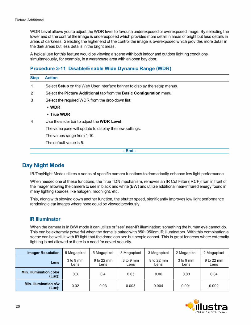
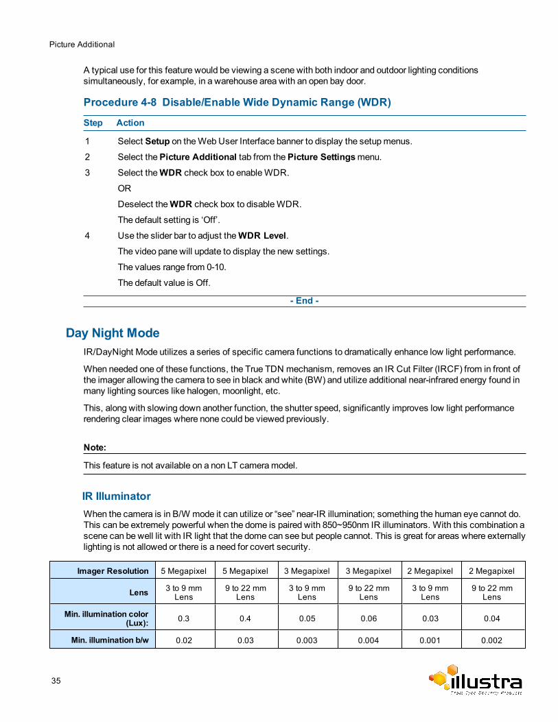
IR IlluminatorWhen the camera is in B/W mode it can utilize or “see” near-IR illumination; something the human eye cannot do.This can be extremely powerful when the dome is paired with 850~950nm IR illuminators. With this combination ascene can be well lit with IR light that the dome can see but people cannot. This is great for areas where externallylighting is not allowed or there is a need for covert security.
Imager Resolution 5 Megapixel 5 Megapixel 3 Megapixel 3 Megapixel 2 Megapixel 2 Megapixel
Lens 3 to 9 mmLens
9 to 22 mmLens
3 to 9 mmLens
9 to 22 mmLens
3 to 9 mmLens
9 to 22 mmLens
Min. illumination color(Lux): 0.3 0.4 0.05 0.06 0.03 0.04
Min. illumination b/w(Lux): 0.02 0.03 0.003 0.004 0.001 0.002
20
Picture Additional
Dynamic range (db) 90 90 96 96 96 96
Procedure 3-12 Enable / Disable IR Illuminator
Step Action
1 Select Setup on theWebUser Interface banner to display the setupmenus.
2 Select thePicture Additional from theBasic Configurationmenu.3 Select theEnable IR Illuminator check box to enable IR Illuminator.
OR
Deselect theEnable IR Illuminator check box to disable IR Illuminator.The default setting is ‘Enabled’.
- End -
Day Night ModeThe dome provides a black-and-white (B/W)mode to improve camera performance when the light level falls belowcertain thresholds. This allows clear images to be obtained under low-light conditions. There are three Day/Nightsettings:Forced Color, Forced B/W and Auto.
Procedure 3-13 Configure Day Night Mode
Step Action
1 Select Setup on theWebUser Interface banner to display the setupmenus.
2 Select thePicture Additional from theBasic Configurationmenu.3 Select aDay Night Mode setting from the drop-downmenu:
• Forced Color - enable full-time color mode.• Forced B/W - enable full-time black and white mode.
• Auto Low- camera will adjust between BW andColor depending on light levels.
• Auto Mid - camera will give a good balance of Color and BW depending on the scene.
• Auto High - increases the chance of switching to BW mode as light levels drop.
• Manual - a slider bar will display, the user can adjust the setting to suit the environment.The default setting is 'Auto Low'.
- End -
Picture AdjustmentAdjust brightness, contrast and saturation of the image displayed on the video pane.
Procedure 3-14 Adjust the Brightness, Contrast and Saturation
Step Action
1 Select Setup on theWebUser Interface banner to display the setupmenus.
2 Select thePicture Additional tab from theBasic Configurationmenu.
21
Picture Additional
3 Select to start the video stream if it is not already active.
The video pane will display the current camera view.
4 Use the slider bars to adjust:
• Brightness• Contrast• Saturation• SharpnessThe video pane will update to display the new settings.
The values range from 0% to 100%.
- End -
Procedure 3-15 Restore Picture Balance Defaults
Step Action
1 Select Setup on theWebUser Interface banner to display the setupmenus.
2 Select thePicture Settings tab from theBasic Configurationmenu.3 Select Defaults to restore the default settings.
The default values are:
• Brightness: 50%• Contrast: 50%• Saturation: 50%• Sharpness: 50%
- End -
White BalanceWhite balance (the ability to keep whites looking white) is normally compensated for automatically via the defaultAutoWhite Balance setting.
Manual White Balance is available when specific color temperature settings want to be set and preserved. Thiscan be done using the red and blue slider adjustments set for optimal viewing.
Procedure 3-16 Configure Auto White Balance
Step Action
1 Select Setup on theWebUser Interface banner to display the setupmenus.
2 Select thePicture Basic tab from theBasic Configurationmenu.
3 Select to start the video stream if it is not already active.
The video pane will display the current camera view.
4 Select the requiredWhite Balance from the drop-downmenu:
22
Lens Calibration
• Auto Wide: Suitable for a wider than normal range of lighting conditions• Auto Normal: Suitable for a normal range of lighting conditions• Sunny: Suitable for sunny conditions• Shadow: Suitable for shady conditions• Indoor: Suitable for indoor conditions• Lamp: Suitable for artificial light conditions• Manual: Adjustable red and blue balance• ROI Manual• ROI AutoThe default setting is ‘Auto Normal’.
- End -
Procedure 3-17 Manually Select White Balance
Step Action
1 Select Setup on theWebUser Interface banner to display the setupmenus.
2 Select thePicture Basic tab from theBasic Configurationmenu.
3 Select to start the video stream if it is not already active.
The video pane will display the current camera view.
4 SelectManual from theWhite Balance drop-downmenu.
The Red and Blue slider bars will be displayed.
5 Use the slider bars to adjust theRed andBlue balance.The live video pane will update to display the new settings.
The red and blue values range from 1% to 100%.
The default settings are Red 18% and Blue 18%.
- End -
Lens CalibrationUse the lens calibration process to recover focus and zoom after motor stalling has occurred. Motor step stallingis rare but it can occur during shipping or throughmishandling of the camera. If the One Touch focus at Wide orTele is not working through the zoom range, the camera requires lens calibration. The lens calibration tool usesinfinity focus curves to align the camera lens and correct problems focusing at Wide or Tele.
You can run a lens calibration from the Lens Calibration tab.
Note:
Objects at least 30 feet (9.144m) away from the camera sholud be in the Field Of Vision
23
Date / Time / OSD
Procedure 3-18 Run a Lens Calibration
Step Action
1 Select Setup on theWeb Interface Banner to display the setupmenus.
2 Select Picture Settings from theVideomenu.3 Select the Lens Calibration tab.4 Select Start Calibration and wait for the camera lens initialization to complete.5 Drag theStep 1: Focus at WIDE slider bar up and down until you are satisfied with the picture focus,
and select Apply to apply your changes.6 Drag theStep 2: Focus at TELE slider bar up and down until you are satisfied with the picture focus,
and select Apply to apply your changes.7 Drag theStep 3: Re Focus at TELE slider bar up and down until you are satisfied with the picture focus,
and select Apply to apply your changes.8 To confirm the success of the lens calibration, selec thePicture Basic tab from thePicture Settings
menu and verify that the image is in focus through the zoom range.
Use theOneTouch button to automatically focus the area of view highlighted in the yellow box displayedin the video pane.
- End -
Date / Time / OSDChange the camera name, date and time and enable OSD.
Camera NameThe camera namewill be displayed on theWebUser Interface banner and the on-screen display for the camera.This namewill also be displayed when using Illustra Connect or ONVIF.
Procedure 3-19 Change the Camera Name
Step Action
1 Select Setup on theWebUser Interface banner.
2 Select theDate/Time/OSD tab in theBasic Configurationmenu.3 Enter the name of the camera in theCamera Friendly Name text box.
- End -
24
Date / Time / OSD
Date / TimeSet the date and time on the camera.
Procedure 3-20 Configuring the Date and Time
Step Action
1 Select Setup on theWebUser Interface banner to display the setupmenus.
2 Select the Date/Time/OSD from theBasic Configurationmenu.3 Select the Time 24-hour check box to enable the 24-hour clock.
Or
Deselect the Time 24-hour check box to enable the 12-hour clock.The default setting is ‘24-hour’.
4 Select theDate Display Format from the drop-downmenu:
• DD/MM/YYYY• MM/DD/YYYY• YYYY/MM/DDThe default setting is ‘YYYY/MM/DD’.
5 Select the Time Zone from the drop-downmenu.
The default setting is ‘(GMT-05:00) Eastern Time (US & Canada)
6 Select theSet Time setting by selecting the radio buttons:• Manually• via NTPThe default setting is ‘Manually’.
7 If you select Manually in step 5:
c Select the Date (DD/MM/YYYY) using the drop-downmenus.d Select the Time (HH:MM:SS) using the drop-downmenus.
8 If you select via NTP in step 5:
a Enter theNTP Server Name in the text box.
- End -
On-Screen Display (OSD)Within OSD you can set enable or disable camera name and time display.
25
Date / Time / OSD
Procedure 3-21 Display or Hide the Camera Name OSD
Step Action
1 Select Setup on theWebUser Interface banner to display the setupmenus.
2 Select the Date/Time/OSD tab in theBasic Configurationmenu.3 Select theCamera Name check box to display the camera name in the OSD.
OR
Deselect theCamera Name check box to hide the camera name in the OSD.The default setting is ‘Disabled’.
- End -
Procedure 3-22 Display or Hide the Camera Time OSD
Step Action
1 Select Setup on theWebUser Interface banner to display the setupmenus.
2 Select the Date/Time/OSD tab in theBasic Configurationmenu.3 Select the Time check box to display the camera name in the OSD.
OR
Deselect the Time check box to hide the camera name in the OSD.The default setting is ‘Disabled’.
- End -
26
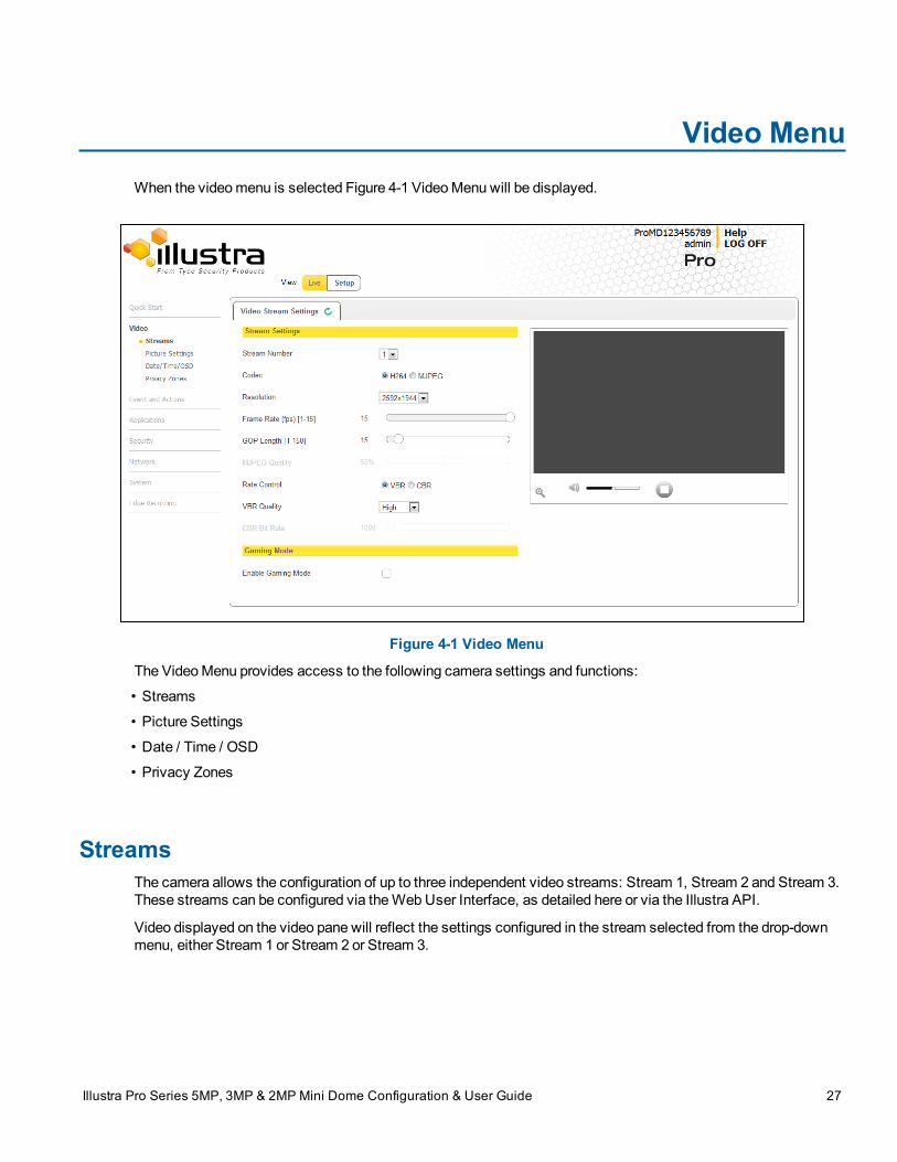
Video MenuWhen the videomenu is selected Figure 4-1 VideoMenu will be displayed.
Figure 4-1 Video Menu
The VideoMenu provides access to the following camera settings and functions:
• Streams
• Picture Settings
• Date / Time / OSD
• Privacy Zones
StreamsThe camera allows the configuration of up to three independent video streams: Stream 1, Stream 2 and Stream 3.These streams can be configured via theWebUser Interface, as detailed here or via the Illustra API.
Video displayed on the video pane will reflect the settings configured in the stream selected from the drop-downmenu, either Stream 1 or Stream 2 or Stream 3.
Illustra Pro Series 5MP, 3MP & 2MP Mini Dome Configuration & User Guide 27
Configuring the Video Stream
Caution
Note:
Stream 3will be used by theWebUser Interface when noQuicktime application is present on the PC. To obtainthe cameras highest resolution video on theWebUser Interface, Quicktime should be downloaded and installed.
Alarm Video
Edge RecordingCamera can directly record specific events (MD, DIO and Face detection) directly to SD card. User can choseeither Stream 1, 2 or 3 to be recorded. When setting upmotion detection on the camera, both streams can beused. Alarm Video is configured in the Edge Recording > Record Settings menu.
Integration with other Illustra API ClientsThe 3 video streams can be configured via theWebUser Interface, as detailed here, or via the Illustra APIinterface. Changes made to the streams via either method will be applied and the video will be displayedaccording to the configuration.
Opening theWebUser Interface live video will allow the stream to be shared with the Illustra API and willminimize the impact on camera resources.
Configuring the Video StreamAdjust the settings for each video stream.
Procedure 4-1 Configure the Video Stream settings
Step Action
1 Select Setup on theWebUser Interface banner to display the setupmenus.
2 Select theStreams tab in theVideomenu.3 Select Stream1 , 2or 3,from the Stream Number drop-downmenu.4 Select the requiredCodec by selecting the radio buttons:
• H264• MJPEGThe default setting is ‘H264’.
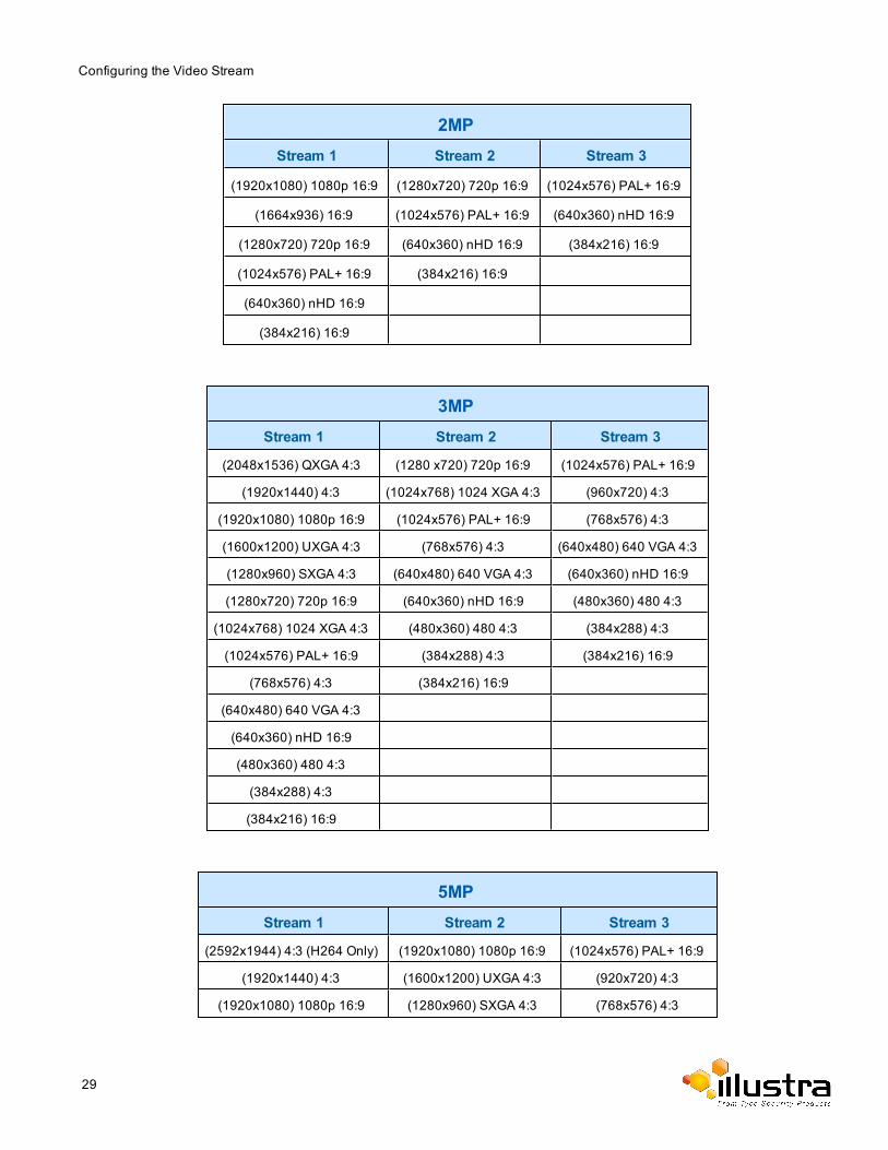
5 Select the requiredResolution from the drop-downmenu.The resolutions available will depend on themodel selected:
28
Configuring the Video Stream
2MPStream 1 Stream 2 Stream 3
(1920x1080) 1080p 16:9 (1280x720) 720p 16:9 (1024x576) PAL+ 16:9
(1664x936) 16:9 (1024x576) PAL+ 16:9 (640x360) nHD 16:9
(1280x720) 720p 16:9 (640x360) nHD 16:9 (384x216) 16:9
(1024x576) PAL+ 16:9 (384x216) 16:9
(640x360) nHD 16:9
(384x216) 16:9
3MPStream 1 Stream 2 Stream 3
(2048x1536) QXGA 4:3 (1280 x720) 720p 16:9 (1024x576) PAL+ 16:9
(1920x1440) 4:3 (1024x768) 1024 XGA 4:3 (960x720) 4:3
(1920x1080) 1080p 16:9 (1024x576) PAL+ 16:9 (768x576) 4:3
(1600x1200) UXGA 4:3 (768x576) 4:3 (640x480) 640 VGA 4:3
(1280x960) SXGA 4:3 (640x480) 640 VGA 4:3 (640x360) nHD 16:9
(1280x720) 720p 16:9 (640x360) nHD 16:9 (480x360) 480 4:3
(1024x768) 1024 XGA 4:3 (480x360) 480 4:3 (384x288) 4:3
(1024x576) PAL+ 16:9 (384x288) 4:3 (384x216) 16:9
(768x576) 4:3 (384x216) 16:9
(640x480) 640 VGA 4:3
(640x360) nHD 16:9
(480x360) 480 4:3
(384x288) 4:3
(384x216) 16:9
5MPStream 1 Stream 2 Stream 3
(2592x1944) 4:3 (H264 Only) (1920x1080) 1080p 16:9 (1024x576) PAL+ 16:9
(1920x1440) 4:3 (1600x1200) UXGA 4:3 (920x720) 4:3
(1920x1080) 1080p 16:9 (1280x960) SXGA 4:3 (768x576) 4:3
29
Configuring the Video Stream
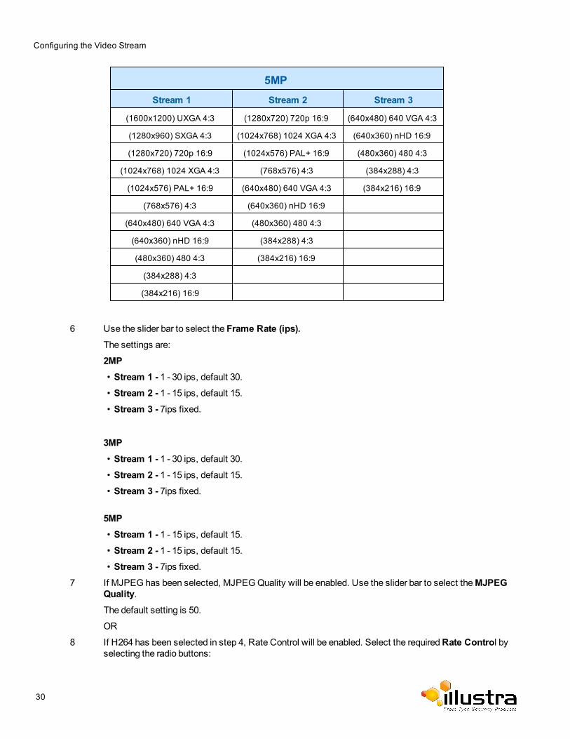
5MPStream 1 Stream 2 Stream 3
(1600x1200) UXGA 4:3 (1280x720) 720p 16:9 (640x480) 640 VGA 4:3
(1280x960) SXGA 4:3 (1024x768) 1024 XGA 4:3 (640x360) nHD 16:9
(1280x720) 720p 16:9 (1024x576) PAL+ 16:9 (480x360) 480 4:3
(1024x768) 1024 XGA 4:3 (768x576) 4:3 (384x288) 4:3
(1024x576) PAL+ 16:9 (640x480) 640 VGA 4:3 (384x216) 16:9
(768x576) 4:3 (640x360) nHD 16:9
(640x480) 640 VGA 4:3 (480x360) 480 4:3
(640x360) nHD 16:9 (384x288) 4:3
(480x360) 480 4:3 (384x216) 16:9
(384x288) 4:3
(384x216) 16:9
6 Use the slider bar to select the Frame Rate (ips).The settings are:
2MP• Stream 1 - 1 - 30 ips, default 30.• Stream 2 - 1 - 15 ips, default 15.• Stream 3 - 7ips fixed.
3MP• Stream 1 - 1 - 30 ips, default 30.• Stream 2 - 1 - 15 ips, default 15.• Stream 3 - 7ips fixed.
5MP• Stream 1 - 1 - 15 ips, default 15.• Stream 2 - 1 - 15 ips, default 15.• Stream 3 - 7ips fixed.
7 If MJPEG has been selected, MJPEGQuality will be enabled. Use the slider bar to select theMJPEGQuality.The default setting is 50.
OR
8 If H264 has been selected in step 4, Rate Control will be enabled. Select the requiredRate Control byselecting the radio buttons:
30
Gaming Mode
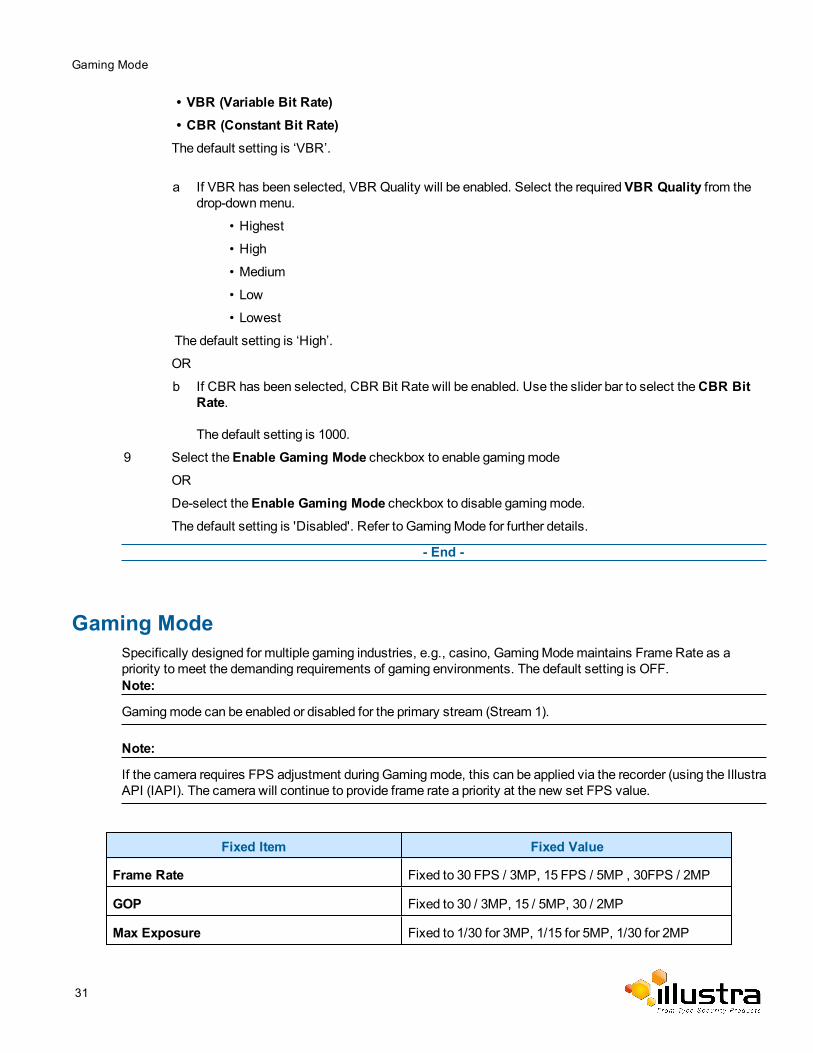
• VBR (Variable Bit Rate)• CBR (Constant Bit Rate)The default setting is ‘VBR’.
a If VBR has been selected, VBR Quality will be enabled. Select the requiredVBR Quality from thedrop-downmenu.
• Highest
• High
• Medium
• Low
• Lowest
The default setting is ‘High’.
OR
b If CBR has been selected, CBR Bit Rate will be enabled. Use the slider bar to select theCBR BitRate.
The default setting is 1000.
9 Select theEnable Gaming Mode checkbox to enable gamingmodeOR
De-select theEnable Gaming Mode checkbox to disable gamingmode.The default setting is 'Disabled'. Refer to GamingMode for further details.
- End -
Gaming ModeSpecifically designed for multiple gaming industries, e.g., casino, GamingModemaintains FrameRate as apriority to meet the demanding requirements of gaming environments. The default setting is OFF.Note:
Gamingmode can be enabled or disabled for the primary stream (Stream 1).
Note:
If the camera requires FPS adjustment during Gamingmode, this can be applied via the recorder (using the IllustraAPI (IAPI). The camera will continue to provide frame rate a priority at the new set FPS value.
Fixed Item Fixed Value
Frame Rate Fixed to 30 FPS / 3MP, 15 FPS / 5MP , 30FPS / 2MP
GOP Fixed to 30 / 3MP, 15 / 5MP, 30 / 2MP
Max Exposure Fixed to 1/30 for 3MP, 1/15 for 5MP, 1/30 for 2MP
31
Picture Settings
Picture Settings
Picture BasicAdjust the Picture Rotation, Focus / Zoom, Exposure andWhite Balance settings.
Picture RotationConfigure the orientation and corridor mode settings. Both settings are optional.
Procedure 4-2 Configure Orientation Settings
Step Action
1 Select Setup on theWebUser Interface banner to display the setupmenus.
2 Select thePicture Basic tab from theVideomenu.3 Select the requiredOrientation setting:
• Mirror• FlipThe video pane will update to display the new settings.
Note:
Whenwall mounting the camera you should select Flip to correct the lens orientation.
- End -
Focus / ZoomThe Focus is manually configured on initial setup. TheOne Touch button can be used to automatically focus thearea of view highlighted in the yellow outlined box displayed on the video pane. This box can bemoved andresized as required and subsequent manual adjustments can be applied if required using the plus andminusvalues. The plus andminus arrows are used tomanually fine tune the image.
The Zoom slider bar is used tomanually zoom in and out to manually configure to picture.
When IR Compensate is enabled, the camera refocuses within 30 seconds of themode transisition between dayto night mode and night to day mode.
Procedure 4-3 Adjust Camera Focus / Zoom
Step Action
1 Select Setup on theWebUser Interface banner to display the setupmenus.
2 Select thePicture Basic tab from theBasic Configurationmenu.
3 Select to start the video stream if it is not already active.
32
Picture Settings
4 Use the plus andminus arrows tomanually configure the focus and the slider bar to adjust zoom settingsuntil the image in clear.
The video pane will update to display the new settings.
- End -
Procedure 4-4 Adjust Camera Focus using OneTouch Autofocus
1 Select Setup on theWebUser Interface banner to display the setupmenus.
2 Select thePicture Basic tab from theBasic Configurationmenu.
3 Select to start the video stream if it is not already active.
4 Draw a region around the area to be focused on within the image.
5 Select theOne Touch button.The camera refocuses to the optimal zoom level for the image.
The video pane will update to display the new settings.
- End -
Procedure 4-5 Enable/Disable IR Compensate
1 Select Setup on theWebUser Interface banner to display the setupmenus.
2 Select thePicture Basic tab from theBasic Configurationmenu.3 Select the IR compensate check box to enable IR compensation
OR
Clear the IR compensate check box to disable IR compensation.
- End -
ExposureConfigure the exposure settings for the camera.
Procedure 4-6 Configure Exposure Settings
Step Action
1 Select Setup on theWebUser Interface banner to display the setupmenus.
2 Select thePicture Settings tab from theBasic Configurationmenu.
3 Select to start the video stream if it is not already active.
4 Select theExposure Method from the drop-downmenu:
• Full Picture Weighted - exposure calculations are based on the entire image.• Center Weighted - exposure calculations are based on a region around the center of theimage.
33
Picture Additional
• Spot - exposure calculations are based on the very center of the image.• ROI Weighted - exposure calculations are based on a region of interest selected.The default setting is CenterWeighted.
5 Select theExposure Offset (F-Stops) from the drop-downmenu.
The default setting is 0.
6 Select theMax Exposure from the drop-downmenu.
The default setting is 1/30.
7 Select theMax Gain from the drop-downmenu.
The default setting is 0db.
The video pane will update to display the new settings.
- End -
Procedure 4-7 Restore Exposure Defaults
Step Action
1 Select Setup on theWebUser Interface banner to display the setupmenus.
2 Select thePicture Settings tab from theBasic Configurationmenu.
3 Select to start the video stream if it is not already active.
4 Select Exposure Defaults to restore the default settings.The default values are:
• ExposureMethod: CenterWeighted
• Exposure Offset (F-Stops): 0.0
• Max Exposure (sec): 1/4 for 5MP, 1/8 for 3MP and 1/8 for 2MP
• Max Gain (dB): 30db for 5MP, 42db for 3MP and 42db for 2MP
- End -
Picture AdditionalConfigureWide Dynamic Range, Day Night Mode, Flicker Control and Picture Adjustments including Brightness,Contrast, White Balance, Saturation and Sharpness displayed in the video pane.
Wide Dynamic RangeWide Dynamic Range (WDR) is a feature that allows viewing of high contrast scenes that include both bright andlow light areas in the same field of view (FOV).
WDR Level allows you to adjust theWDR level to favour an underexposed or overexposed image. By selectingthe lower end of the control the image is underexposed which provides more detail in areas of bright but lessdetails in areas of darkness. Selecting the higher end of the control the image is overexposed which providesmore detail in the dark areas but less details in the bright areas.
34
Picture Additional
A typical use for this feature would be viewing a scene with both indoor and outdoor lighting conditionssimultaneously, for example, in a warehouse area with an open bay door.
Procedure 4-8 Disable/Enable Wide Dynamic Range (WDR)
Step Action
1 Select Setup on theWebUser Interface banner to display the setupmenus.
2 Select thePicture Additional tab from thePicture Settingsmenu.3 Select theWDR check box to enableWDR.
OR
Deselect theWDR check box to disableWDR.
The default setting is ‘Off’.
4 Use the slider bar to adjust theWDR Level.The video pane will update to display the new settings.
The values range from 0-10.
The default value is Off.
- End -
Day Night ModeIR/DayNight Mode utilizes a series of specific camera functions to dramatically enhance low light performance.
When needed one of these functions, the True TDN mechanism, removes an IR Cut Filter (IRCF) from in front ofthe imager allowing the camera to see in black and white (BW) and utilize additional near-infrared energy found inmany lighting sources like halogen, moonlight, etc.
This, along with slowing down another function, the shutter speed, significantly improves low light performancerendering clear images where none could be viewed previously.
Note:
This feature is not available on a non LT cameramodel.
IR IlluminatorWhen the camera is in B/W mode it can utilize or “see” near-IR illumination; something the human eye cannot do.This can be extremely powerful when the dome is paired with 850~950nm IR illuminators. With this combination ascene can be well lit with IR light that the dome can see but people cannot. This is great for areas where externallylighting is not allowed or there is a need for covert security.
Imager Resolution 5 Megapixel 5 Megapixel 3 Megapixel 3 Megapixel 2 Megapixel 2 Megapixel
Lens 3 to 9 mmLens
9 to 22 mmLens
3 to 9 mmLens
9 to 22 mmLens
3 to 9 mmLens
9 to 22 mmLens
Min. illumination color(Lux): 0.3 0.4 0.05 0.06 0.03 0.04
Min. illumination b/w 0.02 0.03 0.003 0.004 0.001 0.002
35
Picture Additional
(Lux):
Dynamic range (db) 90 90 96 96 96 96
Procedure 4-9 Enable / Disable IR Illuminator
Step Action
1 Select Setup on theWebUser Interface banner to display the setupmenus.
2 Select thePicture Additional from theBasic Configurationmenu.3 Select theEnable IR Illuminator check box to enable IR Illuminator.
OR
Deselect theEnable IR Illuminator check box to disable IR Illuminator.The default setting is ‘Disabled’.
- End -
Day Night ModeThe dome provides a black-and-white (B/W)mode to improve camera performance when the light level falls belowcertain thresholds. This allows clear images to be obtained under low-light conditions. There are three Day/Nightsettings:Forced Color, Forced B/W and Auto.
Procedure 4-10 Configure Day Night Mode
Step Action
1 Select Setup on theWebUser Interface banner to display the setupmenus.
2 Select thePicture Additional from theBasic Configurationmenu.3 Select aDay Night Mode setting from the drop-downmenu:
• Auto Low
• AutoMid
• Auto High
• Manual
• Force Color - enable full-time color mode.• Force B/W - enable full-time black and white mode.
• Auto - good balance of Color and BW mode performance.
The default setting is 'Auto Low'.
Picture AdjustmentAdjust brightness, contrast and saturation of the image displayed on the video pane.
Procedure 4-11 Adjust the Brightness, Contrast and Saturation
Step Action
1 Select Setup on theWebUser Interface banner to display the setupmenus.
36
Picture Additional
2 Select thePicture Additional tab from theBasic Configurationmenu.
3 Select to start the video stream if it is not already active.
The video pane will display the current camera view.
4 Use the slider bars to adjust:
• Brightness• Contrast• Saturation• SharpnessThe video pane will update to display the new settings.
The values range from 0% to 100%.
- End -
Procedure 4-12 Restore Picture Balance Defaults
Step Action
1 Select Setup on theWebUser Interface banner to display the setupmenus.
2 Select thePicture Settings tab from theBasic Configurationmenu.3 Select Defaults to restore the default settings.
The default values are:
• Brightness: 50%• Contrast: 50%• Saturation: 50%• Sharpness: 50%
- End -
White BalanceWhite balance (the ability to keep whites looking white) is normally compensated for automatically via the defaultAutoWhite Balance setting.
Manual White Balance is available when specific color temperature settings want to be set and preserved. Thiscan be done using the red and blue slider adjustments set for optimal viewing.
Procedure 4-13 Configure Auto White Balance
Step Action
1 Select Setup on theWebUser Interface banner to display the setupmenus.
2 Select thePicture Basic tab from theBasic Configurationmenu.
3 Select to start the video stream if it is not already active.
The video pane will display the current camera view.
4 Select the requiredWhite Balance from the drop-downmenu:
37
Lens Calibration
• Auto Wide: Suitable for a wider than normal range of lighting conditions• ROI Manual:Region of Interest Manual• ROI Auto:Region of Interest Auto• Auto Normal: Suitable for a normal range of lighting conditions• Sunny: Suitable for sunny conditions• Shadow: Suitable for shady conditions• Indoor: Suitable for indoor conditions• Lamp: Suitable for artificial light conditions• Manual: Adjustable red and blue balanceThe default setting is ‘AutoNormal’.
- End -
Procedure 4-14 Manually Select White Balance
Step Action
1 Select Setup on theWebUser Interface banner to display the setupmenus.
2 Select thePicture Basic tab from theBasic Configurationmenu.
3 Select to start the video stream if it is not already active.
The video pane will display the current camera view.
4 SelectManual from theWhite Balance drop-downmenu.
The Red and Blue slider bars will be displayed.
5 Use the slider bars to adjust theRed andBlue balance.The live video pane will update to display the new settings.
The red and blue values range from 1% to 100%.
The default settings are Red 18% and Blue 18%.
- End -
Lens CalibrationUse the lens calibration process to recover focus and zoom after motor stalling has occurred. Motor step stallingis rare but it can occur during shipping or throughmishandling of the camera. If the One Touch focus at Wide orTele is not working through the zoom range, the camera requires lens calibration. The lens calibration tool usesinfinity focus curves to align the camera lens and correct problems focusing at Wide or Tele.
You can run a lens calibration from the Lens Calibration tab.
Note:
Objects at least 30 feet (9.144m) away from the camera should be in the Field Of Vision
38
Date / Time / OSD
Procedure 4-15 Run a Lens Calibration
Step Action
1 Select Setup on theWeb Interface Banner to display the setupmenus.
2 Select Picture Settings from theVideomenu.3 Select the Lens Calibration tab.4 Select Start Calibration and wait for the camera lens initialization to complete.5 Drag theStep 1: Focus at WIDE slider bar up and down until you are satisfied with the picture focus,
and select Apply to apply your changes.6 Drag theStep 2: Focus at TELE slider bar up and down until you are satisfied with the picture focus,
and select Apply to apply your changes.7 Drag theStep 3: Re Focus at TELE slider bar up and down until you are satisfied with the picture focus,
and select Apply to apply your changes.8 To confirm the success of the lens calibration, select thePicture Basic tab from thePicture Settings
menu and verify that the image is in focus through the zoom range.
Use theOneTouch button to automatically focus the area of view highlighted in the yellow box displayedin the video pane.
- End -
Date / Time / OSDChange the Camera Name, Date and Time and enable On-Screen Display (OSD).
Camera NameThe camera namewill be displayed on theWebUser Interface banner and the on-screen display for the camera.This namewill also be displayed when using Illustra Connect or ONVIF.
Procedure 4-16 Change the Camera Name
Step Action
1 Select Setup on theWebUser Interface banner.
2 Select Date/Time/OSD from theVideomenu.3 Enter the name of the camera in theCamera Friendly Name text box.
- End -
39
Date / Time / OSD
Date / TimeSet the date and time on the camera.
Procedure 4-17 Configuring the Date and Time
Step Action
1 Select Setup on theWebUser Interface banner to display the setupmenus.
2 Select Date/Time/OSD from theVideomenu.3 Select the Time 24-hour check box to enable the 24-hour clock.
Or
Deselect the Time 24-hour check box to enable the 12-hour clock.The default setting is ‘24-Hour’.
4 Select theDate Display Format from the drop-downmenu:
• DD/MM/YYYY• MM/DD/YYYY• YYYY/MM/DDThe default setting is ‘YYYY/MM/DD’.
5 Select the Time Zone from the drop-downmenu.
The default setting is ‘(GMT-05:00) Eastern Time (US & Canada)
6 Select theSet Time setting by selecting the radio buttons:• Manually• via NTPThe default setting is ‘Manually’.
7 If you select Manually in step 5:
c Select the Date (DD/MM/YYYY) using the drop-downmenus.d Select the Time (HH:MM:SS) using the drop-downmenus.
8 If you select via NTP in step 5:
a Enter theNTP Server Name in the text box.
- End -
On-Screen Display (OSD)Within OSD you can set enable or disable camera name and time display.
Procedure 4-18 Display or Hide the Camera Name
Step Action
1 Select Setup on theWebUser Interface banner to display the setupmenus.
40
Privacy Zones
2 Select the Date/Time/OSD tab in theBasic Configurationmenu.3 Select theCamera Name check box to display the camera name in the OSD.
OR
Deselect theCamera Name check box to hide the camera name in the OSD.The default setting is ‘Disabled’.
- End -
Procedure 4-19 Display or Hide the Camera Time
Step Action
1 Select Setup on theWebUser Interface banner to display the setupmenus.
2 Select the Date/Time/OSD tab in theBasic Configurationmenu.3 Select the Time check box to display the camera name in the OSD.
OR
Deselect the Time check box to hide the camera name in the OSD.The default setting is ‘Disabled’.
- End -
Privacy ZonesPrivacy Zones are “masked” sections of the camera’s viewing area. These masks prevent operators of thesurveillance system who do not have access to the camera password from viewing these designated zones.Each zone has four sides, and the zones may overlap to form irregular shapes.
The apparent size of the Privacy Zone adjusts automatically as the zoom level is adjusted. Privacy Zones areuseful for high security areas. For example, you might establish a privacy Zone around a safe’s combination, butstill view people approaching or opening the safe.
Up to 4 rectangular privacy zones can be used on the camera.
Defining a Privacy ZoneCreate a privacy zone on the camera.
Procedure 4-20 Define a Privacy Zone
Step Action
1 Select Setup on theWebUser Interface banner to display the setupmenus.
2 Select Privacy Zones from theVideomenu.
3 Select to start the video stream if it is not already active.
The video pane will display the current camera view.
41

Privacy Zones
4 Click on the edit pencil button. The page updates to display anAdd andCancel button.Enter the privacy zone name in the privacy zone Name text box.The page updates to display anAdd andCancel button.
5 Using the cursor locate the start point for the privacy zone, click and drag on the still image to define theprivacy zone area. As the cursor is moved a red shape will appear on the image which highlights theprivacy zone.
6 Release themouse button.
The selected privacy area will turn yellow.
7 Select Add to save the current privacy zone.8 To reselect an alternative area for the privacy zone select Cancel and repeat from step 4.
Note:
When a new privacy zone is created it is automatically enabled, refer to Procedure 5-6 Enable/Disable aPrivacy Zone tomodify this setting.
- End -
Enabling or Disabling a Privacy ZoneSelect a privacy zone to hide or display on the camera.
Procedure 4-21 Enable/Disable a Privacy Zone
Step Action
1 Select Setup on theWebUser Interface banner to display the setupmenus.
2 Select Privacy Zones from theVideomenu.The Privacy Zones tab displays.
3 Select to start the video stream if it is not already active.
4 The video pane will display the current camera view.
5 Select the correspondingEnabled check box to enable the privacy zone.OR
6 Deselect the correspondingEnabled check box to disable the privacy zone.
- End -
42
Privacy Zones
Deleting a Privacy ZoneDelete a privacy zone from the camera.
Procedure 4-22 Delete a Privacy Zone
Step Action
1 Select Setup on theWebUser Interface banner to display the setupmenus.
2 Select Privacy Zones from theVideomenu.The Privacy zones tab displays.
3 Select the correspondingDelete check box tomark the privacy zone for deletion.
Note:
More than one privacy zone can be deleted at a time. The Select All check box can also be used.
4 Select Delete to delete the selected privacy zones.5 You will be prompted to confirm the deletion.
6 Select OK to confirm the deletion.
Or
Select Cancel.
- End -
43
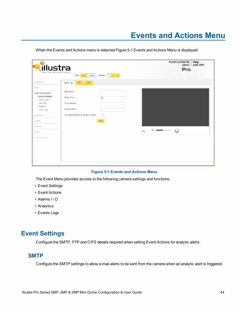
Events and Actions MenuWhen the Events and Actions menu is selected Figure 5-1 Events and Actions Menu is displayed.
Figure 5-1 Events and Actions Menu
The Event Menu provides access to the following camera settings and functions:
• Event Settings
• Event Actions
• Alarms I / O
• Analytics
• Events Logs
Event SettingsConfigure the SMTP, FTP and CIFS details required when setting Event Actions for analytic alerts.
SMTPConfigure the SMTP settings to allow e-mail alerts to be sent from the camera when an analytic alert is triggered.
Illustra Pro Series 5MP, 3MP & 2MP Mini Dome Configuration & User Guide 44
Event Settings
Note:
SMTP settings must be configured to enable email alerts when using analytics.
Procedure 5-1 Configure SMTP Settings
Step Action
1 Select Setup on theWebUser Interface banner to display the setupmenus.
2 Select Event Settings from theEvents and Actionsmenu.3 Select theSMTP tab.
4 Select the Enable SMPT check box to enable SMTP.
Text boxes on the tab become available for entry
OR
Deselect the Enable check box to disable SMTP.
The default setting is 'Disabled'.Note:
When in Enhanced Security mode, enabling SMTP requires the admin account password.
5 Enter the IP Address of themail server in theMail Server text box.6 Enter the server port in theServer Port text box.
The default setting is ‘25’.
7 Enter the from email address in the From Address text box.8 Enter the email address to send email alerts to in theSend Email to text box.9 Select theUse authentication to log on to server check box to allow authentication details to be
entered.
OR
Deselect theUse authentication to log on to server to disable authentication.The default setting is ‘Disabled’.
10 If ‘Use authentication to log on to server’ check box has been selected:
a Enter the username for the SMTP account in theUsername text box.b Enter the password for the SMTP account in thePassword text box.
11 Select Apply to save the settings.
Note:
Refer to Procedure 7-3 Test the SMTP Settings on page 7-74 to confirm that the SMTP settings areworking as expected.
- End -
45
FTP
FTPConfigure the FTP settings for the FTP server. This is required to send video files from triggered analytic alerts.FTP must be configured to enable FTP video alerts when using analytics.
Note:
FTP settings can also be configured via the Network menu.
This feature is not available on an LT cameramodel
Procedure 5-2 Configure FTP Server Settings
Step Action
1 Select Setup on theWebUser Interface banner to display the setupmenus.
2 Select Event Settings from theEvents and Actionsmenu.3 Select the FTP tab.
4 Select theEnable check box to enable FTP.OR
Deselect theEnable check box to disable FTP.The default setting is ‘Enabled’.
5 If required, select theSecure FTP checkbox.
The default setting is ‘Disabled’.Note:
When in Enhanced Security mode, enabling FTP requires the admin account password.
6 Enter the IP address of the FTP Server in the FTP Server text box.7 Enter the FTP username in theUsername text box.8 Enter the FTP password in thePassword text box.9 Enter the FTP upload path in theUpload Path text box.
Note:
Refer to Procedure 7-5 Test the FTP Settings on page 7-76 to confirm that the FTP settings are workingas expected.
- End -
File Transfer RateThe File Transfer Rate can be limited and amax transfer rate assigned tomanage the amount of FTP bandwidthused.
46
CIFS
Procedure 5-3 Configure the FTP Transfer Rate
Step Action
1 Select Setup on theWebUser Interface banner to display the setupmenus.
2 Select Event Settings from theEvents and Actionsmenu.3 Select the FTP tab.
4 Select the Limit Transfer Rate check box to limited the FTP transfer rate.
OR
Deselect the Limit Tranfer Rate check box to disable limited FTP transfer.
The default setting is ‘Enabled’.
5 Enter theMax Transfer Rate in theMax Transfer Rate (Kbps) textbox.
- End -
Test FTP SettingsTest the SMTP settings that have been configured in Procedure 7-4 Configure FTP Server Settings.
Procedure 5-4 Test the FTP Settings
Step Action
1 Select Setup on theWebUser Interface banner to display the setupmenus.
2 Select Event Settings from theEvents and Actionsmenu.3 Select the FTP tab.
4 Select Test.A sample text file is sent to the specified FTP destination to confirm that FTP settings are correct.
- End -
CIFSThe CIFS feature permits files generated from the camera such as alarm related video to be directed to networkattached file storage via the Common Internet File System protocol. This supplements existing distributionmethods such as FTP, SFTP and email.
Note:
This feature is not available on a LT cameramodel
47
Event Actions
Procedure 5-5 Configure CIFS Server Settings
Step Action
1 Select Setup on theWebUser Interface banner to display the setupmenus.
2 Select Event Settings from theEvents and Actionsmenu.3 Select theCIFS tab.
4 Select theEnable check box to enable CIFS.OR
Deselect theEnable check box to disable CIFS.The default setting is ‘Enabled’.Note:
When in Enhanced Security mode, enabling CIFS requires the admin account password
5 Enter the network path in theNetwork Path text box.6 Enter the domain name in theDomain Name in the text box.7 Enter the username in theUsername text box.8 Enter the password h in thePassword text box.
- End -
Event ActionsThe camera can be commanded to carry out a specified operation when an analytic alert is triggered which aredefined using event actions. Up to 5 event actions can be configured on the camera.
Note:
Scheduled tasks, alarms andmanual camera control always begin when they are selected or scheduled to start.None of these camera actions have a priority over the other.
The event action can be used to configure any combination of the following actions:
• Record a clip to microSD Card.
• Send an external alarm via email that includes alarm detail, where to retrieve the AVI video file and oneJPEG picture of the event if recordingMJPEG tomicroSD Card. If MJPEG is not being recorded onmicroSD Card, then no JPEG picture is sent.
• Send an AVI video file to a pre-configured external FTP server. The video file contains pre and postalarm video buffer.
Note:
A microSD Cardmust be inserted to send an SMTP email, video files and images from triggered analytic alerts.
48
Event Actions
Creating an Event ActionConfigure an event action which can be triggered by an analytic alert.
Procedure 5-6 Create an Event Action
Step Action
1 Select Setup on theWebUser Interface banner to display the setupmenus.
2 Select Event Actions from theEvents and Actionsmenu.3 Select an entry on the event actions list and enter an event action name in theName text box.4 Select theRecord check box to enable the Record Settings.5 Select theEmail check box to send an e-mail to the email address configured in the Configure SMTP
Settings procedure.
6 Select the FTP check box to send a video file to the FTP details configured in the Configure FTP ServerSettings procedure.
7 Select theCIFS check box to send a video file to the SFTP details configured in the Configure CIFSServer Settings procedure.
Note:
1. If Record is selected, the AVI clip is saved to themicroSD card and it will have to be removed from thecamera to view the video file.
2. AVI clips can only be sent via FTP if a microSD card has been installed and FTP has been selected.
3. The selected pre and post event duration buffer is included in any video clips sent via FTP.
8 Audio Playback dropdown.
- End -
Editing a Event ActionModify the details of an existing event action.
Procedure 5-7 Edit an Event Action
Step Action
1 Select Setup on theWebUser Interface banner to display the setupmenus.
2 Select Event Actions from the Events and Actions menu.
3 Select an entry on the event actions list, the following can be edited:
• Name
• Record - Enable/Disable
• Email - Enable/Disable
• FTP - Enable/Disable
• CIFS - Enable/Disable
49
Event Actions
• Audio Playback - select the required audio clip
- End -
Alarms I / O
Note:
This feature is not available on a LT cameramodel
The dome provides two alarm inputs. By connecting alarm devices, such as smoke alarms, twilight sensors, ormotion sensors, to these inputs, you can enhance the usability of your video surveillance system.
For 15 seconds after being triggered any additional individual input changes on that alarm source are only belogged and not generate any other action. This is to reduce the effect that any oscillating alarm source, e.g. if adoor is simply vibrating in the wind, causing a series of alarms to be generated.
Input alarms are triggered upon change of state. Either from opened to closed or from closed to open. The camerareports the current state of each input alarms (open or closed) as well as an active or inactive status in the alarmconfiguration page. Active alarms are also be visible in the current faults page.
The triggering of any input alarm affects scheduled tasks and delay them until at least 30 seconds has passedsince the last digital alarm input was triggered.
Alarm ActionsUpon triggering each alarm input can be configured to trigger a faulty action:
• Activate the digital output contact. This stays active until the alarm is acknowledged and cleared byan operator.
• Send an external alarmWS-Event that includes alarm details
• Send an external alarm via email that includes alarm detail, where to retrieve the AVI video file andone JPEG picture of the event if recordingMJPEG to local storage. If MJPEG is not being recordedon local storage, then no JPEG picture is sent.
• Send an audio file via the dome. If a speaker has been connected to the audio output on the domethe file can be played as the alarm is triggered.
• Send an AVI video file to a pre-configured external FTP server. The video file will contain pre andpost alarm video buffer and audio if enabled and supported, as outlined above.
Note:
1. An active internal alarm only resets when the input state changes to “normal.” A manual reset is notavailable.
2. A microSD Cardmust be inserted to send an SMTP email, video files, audio and images from triggeredalarms.
50
Event Actions
Procedure 5-8 Creating an Alarm
Step Action
1 Select Alarm I/O from theEvent and Actionsmenu.2 Enter the alarm name in theName text box.3 Select theEnabled checkbox to enable the alarm
OR
De-select theEnabled checkbox to disable to alarm.4 Select when the alarm is required to be activated from theNormal drop downmenu. i.e. when the dry
contact is open or closed.
5 Select theOutput check box to enable alarm output.
OR
Deselect theOutput check box to disable alarm output.
6 Select the required configured fault action from theAction drop downmenu.
- End -
Procedure 5-9 Enable/Disable an Alarm
Step Action
1 Select Alarm I/O from theEvent and Actionsmenu.2 Select theEnabled check box to enable the corresponding alarm.
OR
Deselect theEnabled check box to disable the corresponding alarm.
- End -
Enable or Disable Alarm OutputAlarm Output allows the alarm to activate a digital output as an action. For example, this digital output could belinked to an electrical device, i.e. a security light or siren.
Procedure 5-10 Enable/Disable Alarm Output
Step Action
1 Select Alarm I/O from theEvent and Actionsmenu.2 Select theOutput check box to enable alarm output.
OR
Deselect theOutput check box to disable alarm output.
- End -
51
Analytics
Procedure 5-11 Clearing Alarm Output
Step Action
1 Select Alarm I/O from theEvent and Actionsmenu.2 Under Alarm Output, select theApply button to Clear Active Output.
The Alarm Output is cleared.
- End -
AnalyticsAnalytics is a feature which detects and tracks objects in video. Analytics supported are Region of Interest, FaceDetection, Motion Detection, Video Intelligence, and Blur Detection.
Region of Interest (ROI)A region of interest is a defined area of the camera view which considered to be higher priority than areas of non-interest. For example, in secure environments, areas of potential activity could be a specific door or window. Theyare specified by drawing a rectangular overlay on the video stream. The overlay is highlighted in green and anOSD is displayed outlining the size% for the x and y axis. Up to five regions of interest can be configured, all ofwhich can be enabled / disabled.
Procedure 5-12 Configure a Region of Interest
Step Action
1 Select Setup on theWebUser Interface banner to display the setupmenus.
2 Select Analytics from theEvents and Actionsmenu.The ROI tab is displayed.
3 Use the drawing tools to draw the region of interest overlay on the video stream.
4 Enter the name of the region of interest in theName text box.5 Select theEnabled check box to enable the region of interest
OR
Deselect theEnabled check box to disable the region of interest.6 Click Add.
The region of interest is configured.
- End -
52
Analytics
Procedure 5-13 Delete a Region of Interest
Step Action
1 Select Setup on theWebUser Interface banner to display the setupmenus.
2 Select Analytics from theEvents and Actionsmenu.The ROI tab is displayed.
3 Select to delete the corresponding region of interest.
- End -
Face DetectionFace Detection works by detecting human faces and ignoring other objects, such as trees or buildings. Thisfeature can be enabled or disabled and the required face orientation selected.
Procedure 5-14 Enable / Disable Face Detection
Step Action
1 Select Setup on theWebUser Interface banner to display the setupmenus.
2 Select Analytics from theEvents and Actionsmenu.The ROI tab is displayed.
3 To enable Face Detection on the camera:
a Select theEnable Face Detection checkbox.b Select theHighlight Faces checkbox to enable
ORDeselect theHighlight Faces checkbox to disable.
c Select theEnhances Faces checkbox to enable.ORDeselect theEnhances Faces checkbox to disable.
d Select the Face Orientation from the drop-downmenu.
• Top• Left• RightOR
Deselect theEnable Face Detection checkbox to disable Face Detection on the camera.4 Select the required preconfigured action to be taken if a face is detected from theAction drop down
menu.
- End -
53
Analytics
Motion DetectionMotion detection enables you to define a region of interest in the camera’s field of view which can be used totrigger an Event Action. Multiple areas of interest can be selected in the field of view but only one Event Actionmay be triggered.
Motion Detection Best PracticesTo ensure you get the highest quality results when usingMotion Detection on the camera it is recommended thatyou adhere to the following:
• An object exhibitingmotion needs to be at least 8x8 pixels in size to be detected.
• The color of the object (in gray scale) should be approximately 10-15% different than the background.
• Exclude the Time Stamp region frommotion detection, because the time stamp changes constantly andcould register as motion.
• Try not to point cameras into sunlight, because high brightness prevents detection of movement ofbright objects such as a person with a white shirt.
• Avoid areas with persistent motion, such as trees, blinking lights, or spinning signs, by using anappropriate region of interest.
Motion Detection Configuration PaneThe regions of interest within the camera’s field of view are defined using theMotion Detection ConfigurationPane. The regions of interest are set by drawing/highlighting an area on the pane. This is done by using thedrawing tools on theMotion Detection Configuration Pane.
Creating a Motion Detection AlertCreate amotion detection alert on the camera.
Note:
1 If themotion detection video stream is changed after the region of interest has been drawn it is necessaryto re-draw a new region.
2 If the stream settings aremodified themotion detection is disabled and it is necessary to enablemotiondetection again if required.
3 Motion detection can only be enabled on a video stream that uses H.264 with a resolution on 1920x1440or lower.
Procedure 5-15 Create a Motion Detection Alert
Step Action
1 Select Setup on theWebUser Interface banner to display the setupmenus.
2 Select Analytics from theEvents and Actionsmenu.3 Select theEnable motion detection checkbox to enableMotion Detection on the camera.
OR
54
Video Intelligence
Deselect theEnable motion detection checkbox to disable Motion Detection on the camera.4 Select Edit to enable the drawing tools on theMotion Detection Configuration Pane.5 Use themouse cursor to draw the region of interest on the pane. Multiple selections can bemade.
6 Select the sensitivity from theSensitivity drop-downmenu:• Highest• High• Medium• Low• Lowest
7 Select the fault action from theAction drop-downmenu.This fault action is activated whenmotion is detected in the selected region of interest.
Refer to the Create a Fault Action procedure if a fault action has not yet been defined.
8 Select Apply to save the changes.
- End -
Enable or Disable a Motion Detection AlertMotion detection can be turned on and turned off when required.
Procedure 5-16 Enable or Disable a Motion Detection Alert
Step Action
1 Select Setup on theWebUser Interface banner to display the setupmenus.
2 Select Analytics from theEvents and Actionsmenu.3 Select theMotion Detection tab.
TheMotion Detection Configuration pane is displayed.
4 Select theEnable motion detection checkbox to enableMotion Detection on the camera.OR
Deselect theEnable motion detection checkbox to disable Motion Detection on the camera.5 Select Apply to save.
- End -
Video IntelligenceThe camera supports the configuration of Video Intelligence Alerts. You can define Video Intelligence settings thatcan be used to set up Analytics Rules.You can add up to three Analytics Rules by default on the camera web userinterface. You can add up to twenty Analytics Rules and access continuous metadata if you purchase a licensefor "Video Intelligence - Full Suite". See www.illustracameras.com for more information.
Explanations of the Rule Types you can define and information about best practice in configuring the Rule Typesare included below:
55
Video Intelligence
• Object Detection- Used to detect people or objects moving into a region of interest. This alert is similarto amotion-based alert, but it only detects people or objects on entry of the region of interes, that is, theyare not continuously detected if they remain within the region of interest. If the object leaves the cameraview and returns, the search detects them again. Use a higher Overlap setting to detect objects that aremostly inside the region, and use a lower value to detect objects that just brush the edge of the region.Select one or more color filters to further refine alerts.
• Abandoned/Removed - Used to detect a stationary object that is placed, moved, or removed. Adjustthe Amount Changed setting to detect either large or small changes occurring in the region. TheWithinsetting specifies the time period over which the changes can occur (0 seconds means instant change).Draw a region that covers the area in which changes should be detected. Use a higher Overlap setting toavoid detecting nearby changes or changes that are not completely in the region.
• Direction - Used to detect objects moving in a certain direction through a region of interest, for example,a car traveling the wrong way on a road. Set the direction (North, South, East orWest) of motion to bedetected , and the traversal time which is themaximum amount of time the object can take to traversemost of the region. This excludes objects that move too slowly. Draw a thin region in the direction ofmotion that you want to detect. Use a lower Overlap setting to detect objects that aremoving in thedirection but are not necessarily contained within the region. Select one or more color filters to furtherrefine alerts.
• Linger - Used to detect objects lingering in an area of interest. An object is lingering if it remains in theregion of interest. Set the Linger Timewhich is theminimum amount of of time an object must lingerbefore being included in the results. Use a higher Overlap setting to avoid detecting objects that arelingering nearby. Select one or more color filters to further refine alerts.
• Dwell - Use to detect objects dwelling in a region of interest. An object is dwelling if is mostlystationary. Set the Dwell Time which is themimimum amount of time an object must dwell before beingincluded in the results. Draw a region in the area where you want to detect objects dwelling. Use ahigher Overlap setting to avoid detecting objects dwelling nearby. Select one or more color filters tofurther refine alerts.
• Object Enter - Used to detect objects entering the camera view through a doorway or threshold. Drawa region of interest around the entire doorway so that when the door is fully opened, it remainscompletely inside the defined region. For sliding glass doors, include their entire pathway inside theregion of interest. For best results, use a higher Overlap setting. Select one or more color filters to furtherrefine alerts.
• Object Exit - Used to detect objects exiting the camera view through a doorway or threshold. Draw aregion of interest around the entire doorway so that when the door is fully opened, it remains completelyinside the defined region. For sliding glass doors, include their entire pathway inside the region ofinterest. For best results use a higher Overlap setting. Select one or more color filters to further refinealerts.
• Crowd - Used to search for times whenmore than a certain amount of people or objects are in a regionof interest. Draw a region in the area that you want to find objects forming a crowd. Use a higher overlapsetting to avoid objects near the region. Set theMinimum Crowd Size to the number of objects thatmake a crowd.
• Queue Length - Used to detect when a queue is a certain length. Draw three regions of interest toindicate the area occupied when the queue is short, medium, or long. Then select the length of the queueyou are looking for from the drop downQueue Lengthmenu. Empty means that there is no queue andNot Empty means there is a queue of any length.
The Video Intelligence settings allow you to define the parameters which initiate an alarm (an alarm rule). Thisreduces the number of unwanted alarm events. The parameters available are dependent on the type of VideoIntelligence rules which are defined.
56
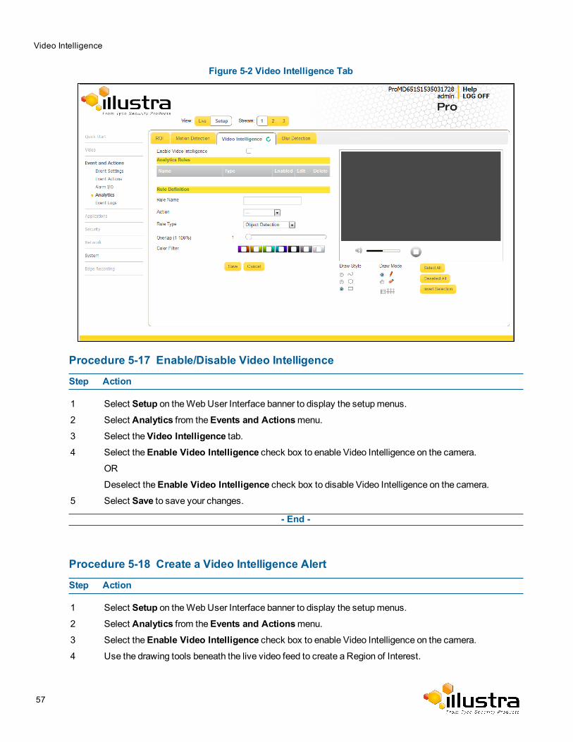
Video Intelligence
Figure 5-2 Video Intelligence Tab
Procedure 5-17 Enable/Disable Video Intelligence
Step Action
1 Select Setup on theWebUser Interface banner to display the setupmenus.
2 Select Analytics from theEvents and Actionsmenu.3 Select theVideo Intelligence tab.4 Select theEnable Video Intelligence check box to enable Video Intelligence on the camera.
OR
Deselect theEnable Video Intelligence check box to disable Video Intelligence on the camera.5 Select Save to save your changes.
- End -
Procedure 5-18 Create a Video Intelligence Alert
Step Action
1 Select Setup on theWebUser Interface banner to display the setupmenus.
2 Select Analytics from theEvents and Actionsmenu.3 Select theEnable Video Intelligence check box to enable Video Intelligence on the camera.4 Use the drawing tools beneath the live video feed to create a Region of Interest.
57
Video Intelligence
5 Type aRule Name for your rule definition in the field provided.6 Select a fault action from theAction drop-downmenu.
This fault action is activated when the parameters of the analytics rule aremet.
7 Select a rule type from theRule Type drop-downmenu:• Object Detection• Abandoned/Removed• Direction• Linger• Dwell• Enter• Exit• Crowd• Queue
8 Use theOverlap slider bar to increase or decrease the percentage of overlap.9 To apply a color filter over the Region of Interest, select one of the sevenColor Filter check boxes.10 Select Save to save your changes.
The rule name and type that you have created appears in theAnalytics Rules table.Note:
When rule type is selected , extra configuration items appear for some rule types. See the section on VideoIntelligence above for information on the extra configuration options for each rule type.
- End -
Procedure 5-19 Enable/Disable an Analytics Rule
Step Action
1 Select Setup on theWebUser Interface banner to display the setupmenus.
2 Select Analytics from theEvents and Actionsmenu.3 Select theVideo Intelligence tab.4 From theAnalytics Rules table, select the check box of the target Analytics Rule to enable the
analytics rule
OR
Deselect the check box of the target Analytics Rule to disable the analytics rule.
- End -
58
Blur Detection
Procedure 5-20 Edit an Analytics Rule
Step Action
1 Select Setup on theWebUser Interface banner to display the setupmenus.
2 Select Analytics from theEvents and Actionsmenu.3 Select theVideo Intelligence tab.
4 From theAnalytics Rules table, select the edit icon across from the analytics rule that you want toedit.
5 Edit the settings in the Rule Definition until you are happy with your changes.
6 Select Save to save your changes.
- End -
Procedure 5-21 Delete an Analytics Rule
Step Action
1 Select Setup on theWebUser Interface banner to display the setupmenus.
2 Select Analytics from theEvents and Actionsmenu.3 Select theVideo Intelligence tab.
4 From theAnalytics Rules table, select the delete icon across from the analytics rule that you wantto delete.
5 Select OK when you are asked to confirm your action.
6 Select Save to save your changes.
- End -
Blur DetectionWith blur detection function enabled, when the camera detects incidents that make video image blur, e.g.redirection, blocking or defocusing, the camera generates an alarm and then take an action you specify
When Blur detection is enabled, it has a polling period of 10minutes.
A Blur Detection start fault is rraised when blur has been detected at 3 successive poling periods (up to 30minutes).
Event Logs
Event LogWhen events are triggered the resulting alarms are displayed in the Event Log with the following information:
59
Event Logs
• # - details the event index.• Event - this is listed as ‘MotionDetected’.• Date created - the time and date when themotion detection was triggered.• Component - internal software component that raised the fault for amotion detection alert. This is listedas ANALYTICS.
• Severity - indicates how serious the fault is. Motion detection alerts are listed as ‘Warning’.
• Detail - extra information that supplements themotion detection alert.• Delete - remove themotion detection alert notification from the fault table.
Procedure 5-22 Display Event Log
Step Action
1 Select Setup on theWebUser Interface banner to display the setupmenus.
2 Select Event Logs from theEvents and Actionsmenu.The Event Log tab displays.
Triggeredmotion detection alerts are displayed.
- End -
Procedure 5-23 Delete Current Events
1 Select Setup on theWebUser Interface banner to display the setupmenus.
2 Select Event Logs from theEvent and Actionsmenu.The Event Logtab displays.
3 Select the correspondingDelete check box tomark themotion detection alert for deletion.OR
Deselect the correspondingDelete check box to keep themotion detection alert.Note:
You can select theSelect All check box tomark all motion detection alerts displayed in the list fordeletion.
4 Select Delete to delete the selectedmotion detection alerts.You are prompted to confirm the deletion.
5 Select OK to confirm the deletion.
OR
Select Cancel.
Fault LogAny system or environmental faults experienced by the camera are displayed in the Fault Log with the following:
• # - details the fault index.• Fault - a description of the fault.
60
Event Logs
• Date created - the time and date when the fault occurred.• Component - internal software component that raised the fault.• Severity - indicates how serious the fault is. The following are supported, in increasing order of severity,Clear, Warning, Critical and Error.
• Detail - extra information that supplements the fault description.• Delete -remove the fault from the fault table.
System FaultsThe following system faults may be raised:
• DiskUsage(Warning) - this warning is raised when the disk utilisation rises above the threshold value“threshold2” held in SYSM.conf. Once an alarm is generated and the disk utilization decreases 1%below the threshold value, the fault is then automatically cleared. The default threshold value is 80%.
• PowerSupplyAlarm(Error) - this fault is raised when one or more of the internal DC power suppliesvoltage level is either too high or too low. Once an alarm is generated and the DC power voltage goesback into the proper range, the fault is then automatically cleared.
ENVM (Environmental Monitor) ComponentThe following environmental faults can be raised by the ENVM (Environmental Monitor) component:
• TemperatureTooHigh (Warning) - this fault is raised when the internal temperature of the enclosure isequal to or exceeds the valueMAX_TEMPERATURE held in ENVM.conf. Once an alarm is generatedand the temperature drops to a level 1 degree below theMAX_TEMPERATURE value the fault is thenautomatically cleared. This is to avoid transient changes in temperature around the threshold.
• TemperatureTooLow (Warning) - a fault is raised when the internal temperature of the enclosure isequal to or is below the valueMIN_TEMPERATURE held in ENVM.conf. Once an alarm is generatedand the temperature drops to a level 1 degree above theMIN_TEMPERATURE value the fault is thenautomatically cleared. This is to avoid transient changes in temperature around the threshold.
Procedure 5-24 Display Current Faults
Step Action
1 Select Setup on theWebUser Interface banner to display the setupmenus.
2 Select Event Logs from theEvent and Actionsmenu.3 Select the Fault Log tab.
Procedure 5-25 Delete Current Faults
Step Action
1 Select Setup on theWebUser Interface banner to display the setupmenus.
2 Select Event Logs from theEvents and Actionsmenu.3 Select the Fault Log tab.
61
Event Logs
4 Select the correspondingDelete check box tomark the fault for deletion.OR
Deselect the correspondingDelete check box to keep the fault.
Note:
You can select theSelect All check box tomark all faults displayed in the list for deletion.
5 Select Delete to delete the selected faults.You are prompted to confirm the deletion.
6 Select OK to confirm the deletion.
OR
Select Cancel.
- End -
62
ApplicationsApplications support allow for the upload of binary files that add custom functionality and value to the camera.Applications are uploaded through theWebUser Interface.
These applications are licensed by Tyco Security Products using a licensing facility.
Applications
Procedure 6-1 Upload an Application
Step Action
1 Select Setup on theWebUser Interface banner to display the setupmenus.
2 Select the Applicationsmenu.The Applications tab displays.
3 Select Browse.The Choose file dialog is displayed.
4 Navigate to the location where the application has been saved.
5 Select the application file then select theOpen button.6 Select Upload.
The upload process begins.
- End -
Available ApplicationsA list of applications currently installed and running are displayed. Each can be started, stopped and removed.
Procedure 6-2 Start, Stop or Remove an Application
Step Action
1 Select Setup on theWebUser Interface banner to display the setupmenus.
2 Select the Applicationsmenu.The Applications tab displays.
3 Select the correspondingApplication checkbox to Start, Stop or Remove.4 Select one of the following options:
a Start to start the application running.b Stop to stop the application running.c Remove to remove the application.
- End -
Illustra Pro Series 5MP, 3MP & 2MP Mini Dome Configuration & User Guide 63
LicenseLicense files for applications are uploaded using the licensing webpage. Available licenses are listed displayingtheir application ID and their license expiry date.
Procedure 6-3 Upload a License File
Step Action
1 Select Setup on theWebUser Interface banner to display the setupmenus.
2 Select License from the Applicationsmenu.3 Select Browse.
The Choose file dialog is displayed.
4 Navigate to the location where the license file has been saved.
5 Select the license file then select theOpen button.6 Select Upload.
The upload process begins.
- End -
64
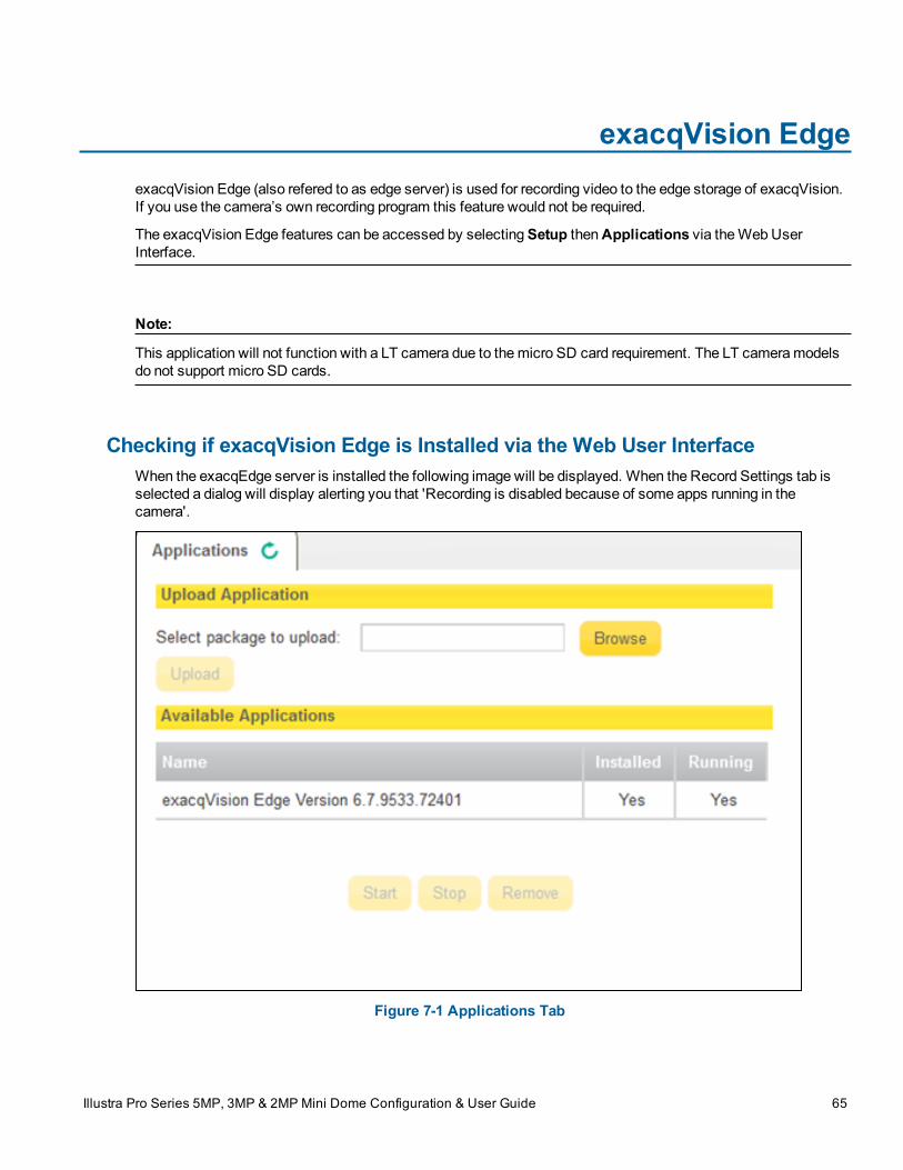
exacqVision EdgeexacqVision Edge (also refered to as edge server) is used for recording video to the edge storage of exacqVision.If you use the camera’s own recording program this feature would not be required.
The exacqVision Edge features can be accessed by selectingSetup thenApplications via theWebUserInterface.
Note:
This application will not function with a LT camera due to themicro SD card requirement. The LT cameramodelsdo not support micro SD cards.
Checking if exacqVision Edge is Installed via the Web User InterfaceWhen the exacqEdge server is installed the following image will be displayed. When the Record Settings tab isselected a dialog will display alerting you that 'Recording is disabled because of some apps running in thecamera'.
Figure 7-1 Applications Tab
Illustra Pro Series 5MP, 3MP & 2MP Mini Dome Configuration & User Guide 65
Install exacqVision EdgeexacqVision Edge can be installed by purchasing an SD card with the exacqVision server and license. Pleasespeak to your Tyco Security integrator to purchase this card.
Procedure 7-1 Install exacqVision Edge Server using Purchased SD Card withexacqVision Server
Step Action
1 Insert the SD card before powering up your camera.
2 The edge server will automatically be installed when the camera starts for the first time.
3 Select Setup thenApplications to confirm the exacqVision Edge Version.
- End -
Procedure 7-2 Install exacqVision Edge Server using the Camera Web User Interface
Step Action
1 Insert a blank SD card into the camera.
2 Select Setup thenApplications.3 Select Browse and navigate to the selected file required for the upload.4 Select Upload this will install the edge server on the PC.
Note:
Youwill have to select Start under the Stop/Start tab to run the edge server even if the edge server has beeninstalled.
- End -
How to use the Edge ServerWhen selected viaSetup andApplications the exacq server will be listed as seen in Figure 1-1. Both theInstalled and Running state will be listed as Yes.Note:
When the SD card is not detected for example when there is no SD card in the camera, it has been improperlymounted, or an error has been found on the SD card itself, there will be an error message displayed when you clickthe Start button to run the edge server. If this happens, insert the SD card or format and properly mount the cardon the camera.
The edge server can be started by selectingStart and stopped by selectingStop.
66
Note:
If the camera reboots when the status of the edge server is listed as Stopped, it will be necessary to select Startas the edge server cannot automatically run unless manually started.
Update the exacqVision ServerWhen a new version is released you can update your existing exacqVision Server.
Procedure 7-3 Update an Application
Step Action
1 Select Setup, Applications thenUpload Application. The Upload tab will display.2 Select Browse. Navigate to where the new firmware files have been saved.
3 Select the new firmware file and select Start. The existing firmware will be replaced by the new firmwareversion.
- End -
Uninstall the exacqVision ServerThe exacqVision Server can be uninstalled if required.
Procedure 7-4 Uninstall the exacqVision Server
Step Action
1 Select Setup, Applications.2 Select the exacqVision Edge Version.
3 Select Remove.4 You will be prompted to confirm the removal, select Yes. The exacqVision server will be removed and the
camera will reboot.
Note:
Youmust unmount or remove the SD card if the edge server files are on the SD card otherwise when the camerareboots the edge sever files will be re-installed.
- End -
Formatting the SD Card
Note:
This procedure will not work with an LT camera. The LT cameramodels do not support micro SD cards.
67

If the SD Card which has the files for the edge server is in use and requires formatting youmust first Stop theedge server and then format the card. When the camera reboots the edge server files will be installed andoperational.
68
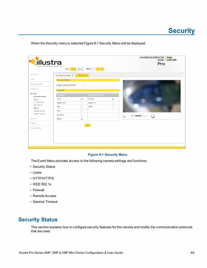
SecurityWhen the Security menu is selected Figure 8-1 Security Menu will be displayed.
Figure 8-1 Security Menu
The Event Menu provides access to the following camera settings and functions:
• Security Status
• Users
• HTTP/HTTPS
• IEEE 802.1x
• Firewall
• Remote Access
• Session Timeout
Security StatusThis section explains how to configure security features for the camera andmodify the communication protocolsthat are used.
Illustra Pro Series 5MP, 3MP & 2MP Mini Dome Configuration & User Guide 69
Security Status
Note:
Any changes in the Security section, either changes to the Security Mode or to an individual protocol, are loggedin the Security Log.
Enhanced SecurityAdmin users can change the Security Mode of the camera from Standard Security to Enhanced Security.
Procedure 8-1 Enable Enhanced Security
Step Action
1 Select Setup on theWebUser Interface banner to display the setupmenus.
2 Select Security Status from theSecuritymenu.3 Select theSecurity Overview tab.
4 Check theEnable Enhanced Security check box to enable enhanced securityOR
Clear theEnable Enhanced Security check box to disable enhanced security.Enhanced Security is disabled by default.
The Security Warning dialog appears.
5 Enter the current password in theCurrent Password text box.6 Enter the new password in theNew Password text box.
Note:
The password for enhanced security must meet the following requirements:
• Be aminimum of seven characters long
• Have at least one character from at least three of the following character groups:
• Upper-case letters
• Lower-case letters
• Numeric characters
• Special characters
7 Re-enter the new password in theConfirm Password text box.8 Click Apply.
Note:
Any changes to the Security Mode are logged in the Security Log
- End -
70
Security Status
Procedure 8-2 Disable Enhanced Security Mode
Step Action
1 Select Setup on theWebUser Interface banner to display the setupmenus.
2 Select Security Status from theSecuritymenu.3 Select theSecurity Overview tab.
4 Clear theEnable Enhanced Security check box to disable enhanced security.Note:
When in Enhanced Security mode, changing the security mode requires the admin account password.
5 Click Apply.Note:
Any changes to the Security mode are logged in the Security Log.
- End -
Setting Communication ProtocolsThis section explains how tomodify the communication protocols that are used. The following communicationprotocols can be enabled: HTTP, FTP, CIFS, Dyn DNS, SMTP, HTTPS, SNMP V3,and SFTP.
Procedure 8-3 Enable/Disable Communication Protocols
Step Action
1 Select Setup on theWebUser Interface banner to display the setupmenus.
2 Select Security Status from theSecuritymenu.3 Select theSecurity Overview tab.
4 Check/Clear the Communication Protocol check box to enable/disable the Communication Protocol.
5 Click Apply to save your settings.Note:
• When in Enhanced Security, enabling/disabling individual protocols requires the adminaccount password.
• Any changes to individual protocol settings are logged in the Security Log.
71
Users
Security LogThe security log records any changes made to the security mode or to an individual protocol.
Procedure 8-4 Display Security Log
Step Action
1 Select Setup on theWebUser Interface banner to display the setupmenus.
2 Select Security Status from theSecuritymenu.3 Select theSecurity Log tab.4 Select Refresh to refresh the log for themost up-to-date information.
- End -
Procedure 8-5 Filter the Security Log
Step Action
1 Select Setup on theWebUser Interface banner to display the setupmenus.
2 Select Security Status from theSecuritymenu.3 Select theSecurity Log tab.4 Enter the number of lines of the log file you would like to view in the Lines (from the end of the log file)
text box.
5 Enter the word or phrase that you would like to search for in the Filter (only lines containing text) textbox.
6 Select Refresh to refresh the log for themost up-to-date information that meets the filter parameters.7 Select Clear to empty the log of its current entries. You will be required to enter your password to do this.
- End -
UsersIn this section you are able to add a user, change a user password and a delete user account. There are threelevels of access: admin, operator and user.
Refer to Appendix A: User Account Access for details on the features which are available to each role.
72
Users
Note:
The default Username is admin and the default Password is admin. Tomaintain security the password on theadmin account should be changed.
View Current User AccountsView a list of the current user accounts assigned to the camera.
Procedure 8-6 View User Accounts
Step Action
1 Select Setup on theWebUser Interface banner to display the setupmenus.
2 Select Users from theSecuritymenu.The current user accounts assigned to the camera will be displayed.
- End -
Add UserAdd a new user account to allow access to the camera.
Procedure 8-7 Add a User
Step Action
1 Select Setup on theWebUser Interface banner to display the setupmenus.
2 Select Users from theSecuritymenu.3 Select theAdd User tab.4 Enter a User Name in theName text box.
The usernamemust start with a letter and can be followed by any alphanumeric values (a-z, A-Z, 0-9) andthe following special characters, underscore(_), dash(-), or dot(.)
5 Select aRole:• admin
• operator
• user
Refer to Appendix A: User Account Access for details on the features which are available to each role.
6 Enter a password in thePassword text box.The passwordmust start with an alphanumeric character and is case sensitive, it can containalphanumeric characters with a length of between 4 and 32 characters.Note:
The password for enhanced security must meet the following requirements:
• Be aminimum of seven characters long
• Have at least one character from at least three of the following character groups:
73
Users
• Upper-case letters
• Lower-case letters
• Numeric characters
• Special characters
7 Enter the same password in theConfirm Password text box.8 Select Apply to save the settings.
The new user account will now be displayed in the Users list on theUsers tab.
- End -
Changing the User Accounts PasswordChange the password of an existing user account.
Procedure 8-8 Change User Password
Step Action
1 Select Setup on theWebUser Interface banner to display the setupmenus.
2 Select Users from theSecuritymenu.3 Select theChange Password tab.4 Select the user account from theName drop-downmenu.5 Enter the current password for the user account in theCurrent Password text box.6 Enter the new password for the user account in theNew Password text box.
The password is case sensitive and can contain alphanumeric characters with a length of between 4 and32 characters.
7 Enter the same new password in theConfirm New Password text box.8 Select Apply to save the settings.
- End -
Delete a User AccountDelete a user account from the camera.
Note:
The default ‘admin’ account cannot be deleted.
Procedure 8-9 Delete a User Account
Step Action
1 Select Setup on theWebUser Interface banner to display the setupmenus.
2 Select Users from theSecuritymenu.
74
HTTP / HTTPS
The Users tab displays.
3 Select to delete the corresponding user account.
You will be prompted to confirm the deletion.
4 Select OK to delete.
OR
5 Select Cancel.
- End -
HTTP / HTTPSUser can select the option to use HTTP, HTTPS or both. The camera will automatically create an SSL certificatefile to use for HTTPS. It is possible to upload a custom SSL certificate if validation is required.
Procedure 8-10 Specify HTTP Method
Step Action
1 Select Setup on theWebUser Interface banner to display the setupmenus.
2 Select HTTP/HTTPS from theSecuritymenu.3 Select theHTTP Method using the radio buttons
• HTTP
• HTTPS
• Both
- End -
Procedure 8-11 Add a HTTPS Certificate
Step Action
1 Select Setup on theWebUser Interface banner to display the setupmenus.
2 Select HTTP/HTTPS from theSecuritymenu.3 Select Browse to navigate to the certificate location.
The Choose file dialog will be displayed.
4 Navigate to the location where the HTTPS certificate has been saved.
Select the file and select Open.
Note:
The certificate needs tomatch the camera ‘host name’.
5 Select Upload.
75
IEEE 802.1x
Youwill be prompted to confirm that you would like to upload the HTTPS certificate.
6 Select OK to confirm the upload.
OR
Select Cancel.
- End -
Delete a HTTPS CertificateIf you delete the existing certificate it will be replaced by a temporary substitute. The current browser session willbe lost and you will be required to log back in to the cameraWebUser Interface.
Procedure 8-12 Delete a HTTPS Certificate
Step Action
1 Select Setup on theWebUser Interface banner to display the setupmenus.
2 Select HTTP/HTTPS from theSecuritymenu.3 Select Delete.
The camera will display a “Restarting HTTPS Service” page with a progress bar showing the deletionprogress.
4 When complete the camera will return to the log in page.
- End -
IEEE 802.1xThe IEEE 802.1x security feature provides port based network access control i.e. securing corporate networksfrom the attachment of unauthorized devices.
Authentication is carried out through use of the Extensible Authentication Protocol or EAP. Both PEAP and TLSmethods are supported.
Procedure 8-13 Configure IEEE 802.1x Security
Step Action
1 Select Setup on theWebUser Interface banner to display the setupmenus.
2 Select IEEE 802.1x from theSecuritymenu.TheGeneral tab is displayed.
3 Select theEnable IEEE802.1x checkbox to enable IEEE802.1x security .OR
4 De-select theEnable IEEE802.1x checkbox to disable IEEE802.1x security.5 Select theEAPOL Version from the drop-downmenu.
6 Select theEAP Method using the radio buttons.7 Enter the EAP identity name in theEAP Identify textbox.
76
Firewall
8 Select Upload to navigate to theCA Certificate location.The Choose file dialog will be displayed.
9 Navigate to the location where the certificate has been saved.
Select the file and select Open.10 Select Upload.
The upload process will start.
11 If PEAP is selected:
a Enter the required PEAP Password.OR
If TLS is selected -
a Select Upload to navigate to theClient Certificate location.The Choose file dialog will be displayed.
b Navigate to the location where the certificate has been saved.
c Select the file and select Open.d Select Upload.
The upload process will start.
e Enter the requiredPrivate Key Password.
- End -
FirewallConfigure the Basic Filtering and Address Filtering for the firewall.
Basic FilteringEnable or disable basic filtering for the camera this includes:
• ICMP (Internet Control Message Protocol) Blocking
• RP (Reverse Path) Filtering
• SYN Cookie Verification.
Procedure 8-14 Enable/Disable Basic Filtering
Step Action
1 Select Setup on theWebUser Interface banner to display the setupmenus.
2 Select Firewall from theSecuritymenu.The Basic Filtering tab displays.
3 Select the ICMP Blocking check box to enable ICMP blocking.
77
Firewall
OR
Deselect the ICMP Blocking check box to disable ICMP blocking.
The default setting is ‘Disabled’.
4 Select theRP Filtering check box to enable the RP filtering.
OR
Deselect theRP Filtering check box to disable.The default setting is ‘Disabled’.
5 Select SYN Cookie Certification check box to enable SYN cookie certification.
OR
Deselect theSYN Cookie Certification check box to disable.The default setting is ‘Disabled’.
- End -
Address FilteringConfigure the IP or MAC addresses which are denied access to the camera.
Procedure 8-15 Enable/Disable and configure Address Filtering
Step Action
1 Select Setup on theWebUser Interface banner to display the setupmenus.
2 Select Firewall from theSecuritymenu.3 Select theAddress Filtering tab.4 Select Off to disable address filtering completely.
OR
Select Allow to allow address filtering for specified addresses
OR
Select Deny to deny address filtering for specific addresses.The default setting is ‘Off’.
5 If address filtering has been set toAllow orDeny:a Enter an IP or MAC Address to allow / deny in the IP or MAC Address text box in the following
format xxx.xxx.xxx.xxx.Note:
CIDR (Classless Inter-Domain Routing) is supported when using address filtering. If using a CIDRaddress use the following format xxx.xxx.xxx.xxx/xx.
b Select Add.6 Select Apply to save the settings.
- End -
78
Remote Access
Editing an Address FilterEdit an existing address filter.
Procedure 8-16 Edit an Address Filter
Step Action
1 Select Setup on theWebUser Interface banner to display the setupmenus.
2 Select Firewall from theSecuritymenu.3 Select theAddress Filtering tab.4 Edit the IP or MAC Address in the IP or MAC Address text box.5 Select Add to save the changes.
- End -
Deleting an Address FilterDelete an existing address filter.
Procedure 8-17 Delete an Address Filter
Step Action
1 Select Setup on theWebUser Interface banner to display the setupmenus.
2 Select Firewall from theSecuritymenu.3 Select theAddress Filtering tab.
4 Select to delete the corresponding address filter.
- End -
Remote Access
SSH EnableEnables Secure Shell access into the camera, if remote access is permitted by the camera network. This will alsoenable Tyco Security Products Level 3 Technical Support to diagnose any problems on the camera.
Note:
It is recommended to keep SSH Enable disabled. This function should only be enabled this when it is requestedby Tyco Security Products Level 3 Technical Support.
79
Remote Access
Procedure 8-18 Configure SSH
Step Action
1 Select Setup on theWebUser Interface banner to display the setupmenus.
2 Select Remote Access from theSecuritymenu.The Remote Access tab displays.
3 Select theSSH Enable check box to enable SSH.OR
Deselect SSH Enable check box to disable SSH.The default setting is ‘Disabled’.
- End -
ONVIFTheWebUser Interface allows ONVIF functionality to bemanaged at a high level. ONVIF Discovery Mode andUser Authentication can be enabled or disabled.
• ONVIF Discovery Mode allows enabling or disabling discovery of the camera via ONVIF.
• ONVIF User Authentication allows the camera to accept ONVIF commands from all users or onlyauthenticated users. Enabling User Authentication ensures the camera will only execute commandsfrom authenticated users.
The separation of Discovery Mode and User Authentication allows the camera to be set up in a configuration thatsuits requirements for the network and users. The preferred discovery method for the camera is Illustra Connect,and this utilizes ONVIF discovery. It is therefore recommended that ONVIF Discovery Mode is always enabled.
ONVIF Discovery ModeEnable or disable ONVIF discovery on the camera.
Procedure 8-19 Enable/Disable ONVIF Discovery Mode
Step Action
1 Select Setup on theWebUser Interface banner to display the setupmenus.
2 Select Remote Access from theSecuritymenu.The Remote Access tab displays.
3 Select theONVIF Discovery Mode check box to enable ONVIF Discovery Mode.OR
Deselect ONVIF Discovery Mode check box to disable ONVIF Discovery Mode.The default setting is ‘Enabled’.
- End -
80
Session Timeout
ONVIF User Authentication
To utilize ONVIF User Authentication, theremust be at least one admin level user in the ONVIF service.Note:
When in Enhanced Security mode, editing ONVIF User Authentication requires the admin account password.
Procedure 8-20 Enable/Disable ONVIF User Authentication
Step Action
1 Select Setup on theWebUser Interface banner to display the setupmenus.
2 Select Remote Access from theSecuritymenu.The Remote Access tab displays.
3 Select theONVIF User Authentication check box to enable ONVIF User Authentication.OR
Deselect ONVIF User Authentication check box to disable ONVIF User Authentication.The default setting is ‘Enabled’.
- End -
Session TimeoutSession timeout specifies the number of minutes that a web session can remain idle before it is automaticallyterminated.
Procedure 8-21 Set a Session Timeout time
Step Action
1 Select Setup on theWebUser Interface banner to display the setupmenus.
2 Select Session Timeout from theSecuritymenu.The Session Timeout tab displays.
3 Use the slider bar to select theSession Timeout (mins).The default setting is 15minutes.
- End -
81
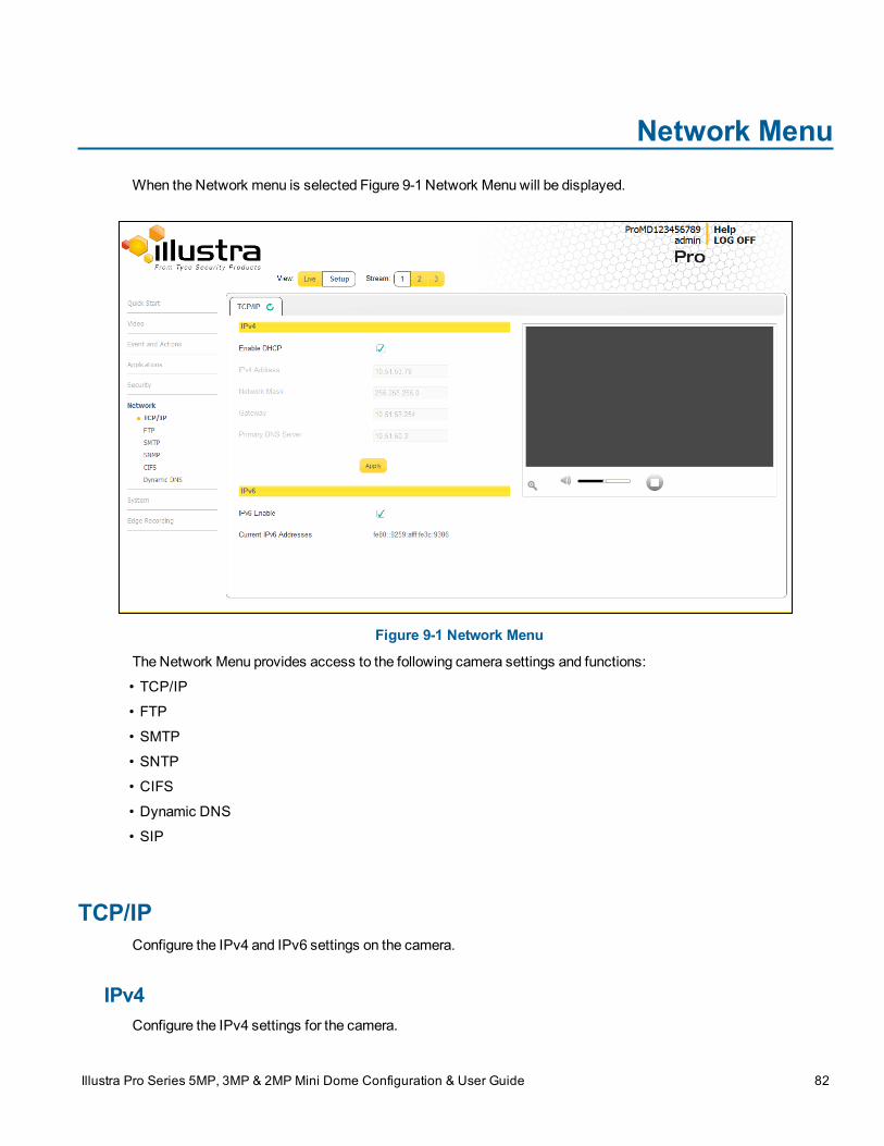
Network MenuWhen the Network menu is selected Figure 9-1 Network Menu will be displayed.
Figure 9-1 Network Menu
The Network Menu provides access to the following camera settings and functions:
• TCP/IP
• FTP
• SMTP
• SNTP
• CIFS
• Dynamic DNS
• SIP
TCP/IPConfigure the IPv4 and IPv6 settings on the camera.
IPv4Configure the IPv4 settings for the camera.
Illustra Pro Series 5MP, 3MP & 2MP Mini Dome Configuration & User Guide 82
TCP/IP
Procedure 9-1 Configure the IPv4 Settings
Step Action
1 Select Setup on theWebUser Interface banner to display the setupmenus.
2 Select TCP/IP from theNetworkmenu.3 Select theEnable DHCP check box to enable DHCP and disable manual settings.
OR
Deselect Enable DHCP to disable DHCP and allow manual settings to be entered.
The default setting is ‘Disabled’.
4 If Enable DHCP has been disabled:
a Enter the IPv4 Address in the IPv4 Address text box in the form xxx.xxx.xxx.xxx.The default setting is ‘192.168.1.168’
b Enter theNetwork Mask in the Network Mask text box xxx.xxx.xxx.xxx.The default setting is ‘255.255.255.0’
c Enter theGateway IP address in Gateway text box xxx.xxx.xxx.xxx.
d Enter thePrimary DNS Server in the Primary DNS Server text box xxx.xxx.xxx.xxx.
e Enter theSecondary DNS Server in the Secondary DNS Server text box xxx.xxx.xxx.xxx.
5 Select Apply to save the settings.
- End -
IPv6Enable IPv6 on the camera.
Procedure 9-2 Enable/Disable IPv6
Step Action
1 Select Setup on theWebUser Interface banner to display the setupmenus.
2 Select TCP/IP from theNetworkmenu.3 Select the IPv6 Enable check box to enable IPv6 on the camera.
OR
Deselect the IPv6 Enable check box to disable IPv6 on the camera.The default setting is ‘Enabled’.
If IPv6 is enabled the Link Local and DHCP address will be displayed beside ‘Current IPv6 Addresses’ ifavailable.
- End -
83
FTP
FTPConfigure the FTP settings for the FTP server. This is required to send video files from triggered analytic alerts.FTP must be configured to enable FTP video alerts when using analytics.
Note:
1 FTP settings can also be configured via the Network menu.
2 This feature is not available on a LT cameramodel
Procedure 9-3 Configure FTP Server Settings
Step Action
1 Select Setup on theWebUser Interface banner to display the setupmenus.
2 Select FTP from theNetworkmenu.3 Select theEnable check box to enable FTP.
OR
Deselect theEnable check box to disable FTP.The default setting is ‘Enabled’.Note:
When in Enhanced Security mode, enabling FTP requires the admin account password.
4 If required, select theSecure FTP checkbox.
The default setting is ‘Disabled’.
5 Enter the IP address of the FTP Server in the FTP Server text box.6 Enter the FTP port in the FTP Port text box.
The default setting is 21.
7 Enter the FTP username in theUsername text box.8 Enter the FTP password in thePassword text box.9 Enter the FTP upload path in theUpload Path text box.
Note:
When entering the upload path the following format should be used '//<name of ftp directory>/<folder>'
- End -
File Transfer RateThe File Transfer Rate can be limited and amax transfer rate assigned tomanage the amount of FTP bandwidthused.
84
SMTP
Procedure 9-4 Configure the FTP Transfer Rate
Step Action
1 Select Setup on theWebUser Interface banner to display the setupmenus.
2 Select Event Settings from theEvents and Actionsmenu.3 Select the FTP tab.
4 Select the Limit Transfer Rate check box to limit the FTP transfer rate.
OR
Deselect the Limit Transfer Rate check box to disable limited FTP transfer.
The default setting is ‘Enabled’.
5 Enter theMax Transfer Rate in theMax Transfer Rate (Kbps) textbox.The default setting is 50.
- End -
Test FTP SettingsTest the FTP settings that have been configured correctly.
Procedure 9-5 Test the FTP Settings
Step Action
1 Select Setup on theWebUser Interface banner to display the setupmenus.
2 Select FTP from theNetworkmenu.3 Select the FTP tab.
4 Select Test.A sample text file will be sent to the specified FTP destination to confirm that FTP settings are correct.
- End -
SMTPConfigure the SMTP settings to allow e-mail alerts to be sent from the camera when an analytic alert is triggered.
Note:
SMTP settings must be configured to enable email alerts when using analytics.
Procedure 9-6 Configure SMTP Settings
Step Action
1 Select Setup on theWebUser Interface banner to display the setupmenus.
2 Select SMPT from theNetworkmenu.
85
SNMP
TheSMPT tab displays.3 Check theEnable SMPT check box to enable SMPT.
Text boxes on the tab become available for entry.Note:
When in Enhanced Security mode, enabling SMTP requires the admin account password.
4 Enter the IP Address of themail server in theMail Server text box.5 Enter the server port in theServer Port text box.
The default setting is ‘25’.
6 Enter the from email address in the From Address text box.7 Enter the email address to send email alerts to in theSend Email to text box.8 Select theUse authentication to log on to server check box to allow authentication details to be
entered.
OR
Deselect theUse authentication to log on to server to disable authentication.The default setting is ‘Disabled’.
9 If ‘Use authentication to log on to server’ check box has been selected:
a Enter the username for the SMTP account in theUsername text box.b Enter the password for the SMTP account in thePassword text box.
10 Select Apply to save the settings.
- End -
SNMPThe camera introduces support for the Simple Network Management Protocol making it easier to manage on an IPnetwork.
The SNMP support includes support for V2 and V3. Using V2means no authentication is required to access thedata and results are unencrypted. V3 offers enhanced encryption and authentication security features.
Procedure 9-7 Configure SNMP Settings
Step Action
1 Select Setup on theWebUser Interface banner to display the setupmenus.
2 Select SNMP from theNetworkmenu.3 Enter a location reference in the Location text box.4 Enter an SNMP managing contact reference in theContact text box.5 If usingV2:
a Select theEnable V2 checkbox.b Enter the authorized ID for reading SNMP data in theRead Community text box.
86
CIFS
c Enter the Trap Community.d Enter the Trap Address.e Select Apply.OR
If usingV3:a Select theEnable V3 checkbox.b Enter theRead User.c Select theSecurity Level from the drop downmenu:
- noauth:No authentication / no encryption.- auth:Authentication / no encryption. A user password is required. It is symmetrically encryptedusing either MD5 or SHA.- priv: Authentication / encryption. A user password is required as is symmetrically encrypted usingeither MD5 or SHA. A data encryption password is required as is symmetrically encrypted usingeither DES or AES.
d Select theAuthentication Type using the radio buttons.e Enter the Authentication Password
f Select theEncryptionType using the radio buttons.g Enter theEncryption Passwordh Select Apply.
- End -
CIFSThe CIFS feature permits files generated from the camera such as alarm related video to be directed to networkattached file storage via the Common Internet File System protocol. This supplements existing distributionmethods such as FTP, SFTP and email.
Note:
This feature is not available on a LT cameramodel
Procedure 9-8 Configure CIFS Server Settings
Step Action
1 Select Setup on theWebUser Interface banner to display the setupmenus.
2 Select CIFS from theNetworkmenu.3 Select theEnable check box to enable CIFS.
OR
Deselect theEnable check box to disable CIFS.The default setting is ‘Disabled’.Note:
87
Dynamic DNS
When in Enhanced Security mode, enabling CIFS requires the admin account password.
4 Enter the network path in theNetwork Path text box.
Note:
When entering the network path the following format should be used '//<IP Address>/<folder name>'
5 Enter the domain name in theDomain Name in the text box.6 Enter the username in theUsername text box.7 Enter the password h in thePassword text box.
- End -
Dynamic DNSDynamic DNS is supported for updating, in real time a changing IP address on the Internet to provide a persistentdomain name for a resource that may change location on the network. RFC 2136 Dynamic Updates in the DomainName System. In this situation the camera talks only to the DHCP server and the DHCP server is responsible forupdating the DNS server. The camera sends its hostname to the DHCP server when requesting a new lease andthe DHCP server updates the DNS records accordingly. This is suitable for an intranet style configuration wherethere is an internal DHCP and DNS service and the user wants only to access their camera within their ownnetwork.
By default, whenmaking a DHCP request the camera will transmit its hostname as part of the DHCP request.This option is not user configurable. The cameras hostnamematches the configurable parameter “camera name”on theWebUser Interface. Any DHCP request will contain the cameras hostname for use of the DHCP server toforward to an appropriate DNS server.
Dynamic DNSConfigure the Dynamic DNS settings for the camera.
Procedure 9-9 Configure Dynamic DNS
Step Action
1 Select Setup on theWebUser Interface banner to display the setupmenus.
2 Select Dynamic DNS from theNetworkmenu.3 Select theService Enable check box to enable Dynamic DNS.
OR
Deselect Service Enable check box to disable Dynamic DNS.The default setting is ‘Disabled’.
4 If Service Enable has been enabled:
a Enter the Camera Alias in the text box.
b Select a Service Provider from the drop-down list:
• dyndns.org
88
SIP
• easydns.com• no-ip.com• zerigo.com• dynsip.org• tzo.comc Enter aUsername in the text box.d Enter aPassword in the text box.e EnterService Data in the text box.
5 Select Apply to save the settings.
- End -
SIPThe Session Initiation Protocol (SIP) feature enables the camera to be configured as a SIP User Agent that canregister with a SIP server to make and receive audio calls to another SIP device, for example, a SIP IP phone orsoftphone. The camera can operate as a SIP phone if it is equipped with an external microphone and speaker. Thecamera can also be configured tomonitor the audio from a SIP call andmake this available as an RTSP/RTPstream.
Enable/Disable SIPEnable/Disable SIP on the camera.
Procedure 9-10 Enable/Disable SIP
Step Action
1 Select Setup on theWebUser Interface banner to display the setupmenus.
2 Select SIP from theNetworkmenu.3 Check theEnabled check box to enable SIP
OR
Clear theEnabled check box to disable SIP.The default setting is 'Disabled'.
4 Click Apply to save your settings.Note:
After you enable SIP, the camera reboots automatically.
- End -
89
SIP
Configure the SIP Server SettingsConfigure the SIP server settings on the camera.
Procedure 9-11 Configure the SIP Server Settings
Step Action
1 Select Setup on theWebUser Interface banner to display the setupmenus.
2 Select SIP from theNetworkmenu.3 Check theEnabled check box to enable SIP.4 Enter the IP address of the SIP Server in theDomain text box.5 Enter the SIP account username in theUsername text box.6 Enter the SIP account password in thePassword text box.7 From theAudio Source dropdownmenu, select the Audio Source for calls:
• Mic - only external microphones are currently supported.8 From theAudio Output dropdownmenu, select an audio output:
• Speaker - the SIP call audio is output to the external speaker.
• Network Stream - the SIP call audio can be streamed using an RTSP Audio Stream.
9 Click Apply to save your settings.Note:
After you enable SIP, the camera reboots automatically.
- End -
Place a SIP callPlace a SIP call on the camera.
Procedure 9-12 Place a SIP call
Step Action
1 Select Setup on theWebUser Interface banner to display the setupmenus.
2 Select SIP from theNetworkmenu.3 Enter the SIP Extension number in theExtension text box.4 Click Dial to activate the call.5 Click Hang up to end the call.
Note:
The Staus Log, located below the Dial and Hang up buttons, reports the status of SIP connection andactive calls.
90
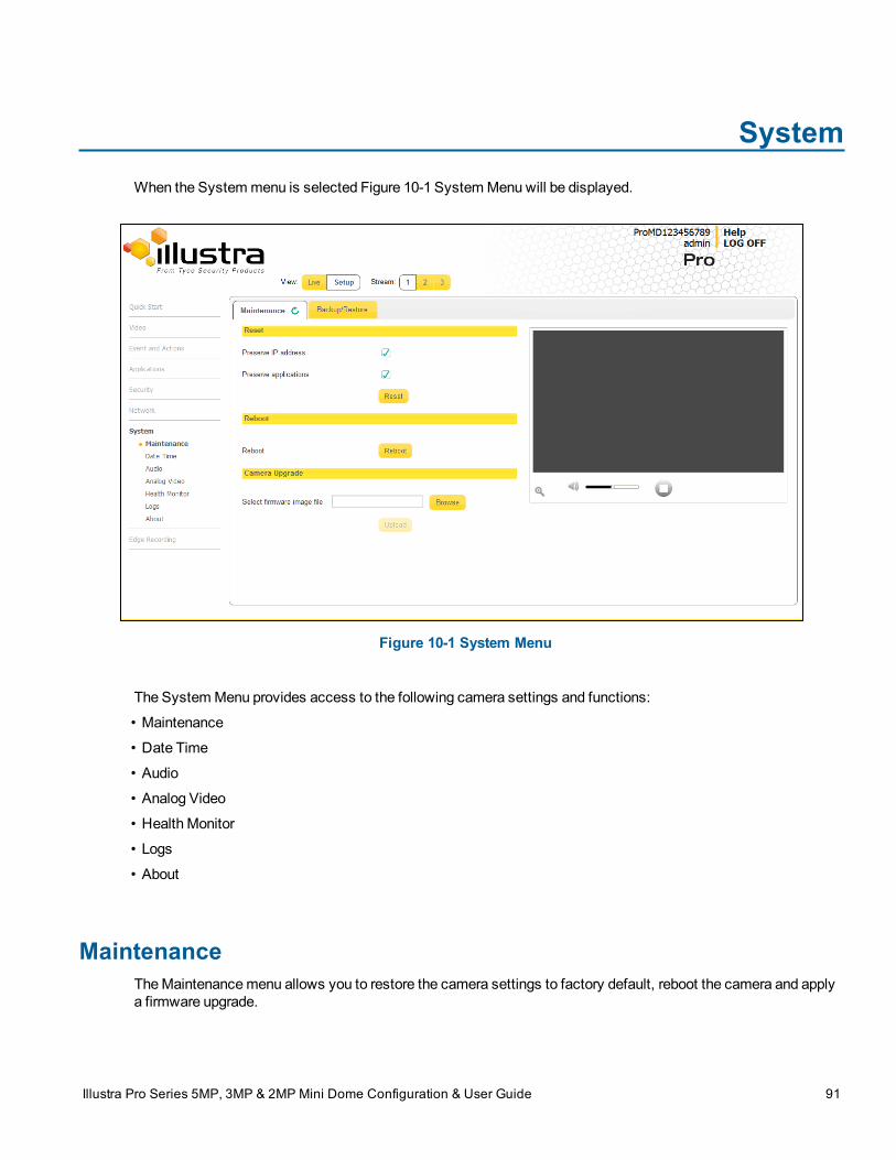
SystemWhen the Systemmenu is selected Figure 10-1 SystemMenuwill be displayed.
Figure 10-1 System Menu
The SystemMenu provides access to the following camera settings and functions:
• Maintenance
• Date Time
• Audio
• Analog Video
• Health Monitor
• Logs
• About
MaintenanceTheMaintenancemenu allows you to restore the camera settings to factory default, reboot the camera and applya firmware upgrade.
Illustra Pro Series 5MP, 3MP & 2MP Mini Dome Configuration & User Guide 91
Maintenance
ResetTo perform a physical reset of the camera, refer to Procedure 17-2 Reset the Camera to Factory Default Settingsusing the Reset/Reboot Switch on page 17-154.
Note:
Network settings, presets, patterns and sequences can be retained if required.
Procedure 10-1 Resetting the Camera
Step Action
1 Select Setup on theWebUser Interface banner to display the setupmenus.
2 SelectMaintenance from theSystemmenu.
3 Select thePreserve IP address check box to retain the current network settings during the camerareset.
OR
Deselect thePreserve IP address check box to restore the default networking settings.The default setting is ‘Enabled’.
4 Select thePreserve application check box to retain the current presets, patterns and sequences duringthe camera reset.
OR
Deselect thePreserve application check box to remove existing presets, patterns and sequences.The default setting is ‘Enabled’.
5 Select thePreserve licenses check box to retain the current licenses during the camera resetOR
Deselect thePreserve licenses check box to remove existing licenses. The default setting is 'Enabled'.6 Select Reset
Youwill be prompted to confirm the camera reset.
7 Select OK to confirm. TheWebUser Interface will display a “Camera Resetting” page with a progressbar showing the reboot progress.
When the camera is restarted it will take 2 - 3minutes until it is online and ready to be accessed andcontrolled.
OR
Select Cancel.8 The Log in page will be displayed.
Refer to Procedure 3-1 Log in to the Camera on page 3-10 to log back into the cameraWebUserInterface.
- End -
92
Maintenance
RebootTo perform a physical reboot of the camera, refer to Procedure 17-1 Reboot the camera using the Reboot/ResetSwitch on page 17-154.
Procedure 10-2 Reboot the Camera
Step Action
1 Select Setup on theWebUser Interface banner to display the setupmenus.
2 SelectMaintenance from theSystemmenu.
3 Select Reboot.You will be prompted to confirm the camera reboot.
4 Select OK to confirm.
TheWebUser Interface will display a “Camera Rebooting” page with a progress bar showing the rebootprogress.
When the camera is restarted it will take 2 - 3minutes until it is online and ready to be accessed andcontrolled.
OR
Select Cancel.5 The Log in page will be displayed.
- End -
Camera Firmware UpgradeThe camera can be upgraded using firmware provided by Illustra. Alternatively, the camera can also be upgradedusing Illustra Connect. Refer to the Illustra Connect User Guide for further information.
Note:
All existing camera settings aremaintained when the firmware is upgraded.
CautionYou should only use firmware that has been provided by Illustra. Using any other firmwaremay cause amalfunction and damage the camera.
Procedure 10-3 Upgrade Camera Firmware
Step Action
1 Select Setup on theWebUser Interface banner to display the setupmenus.
2 SelectMaintenance from theSystemmenu.
93
Backup/Restore
3 Select Browse.The Choose file to Upload dialog will be displayed.
4 Navigate to the location where the firmware file has been saved.
5 Select the firmware file then select theOpen button.6 Select Upload.
The file transfer will begin. Do not disconnect power to the camera during the upgrade process. Thecamera restarts automatically after the updates have been completed, this can take from 1 to 10minutes.
The Log in page will be displayed.
Refer to Procedure 3-1 Log in to the Camera on page 3-10 to log back into the cameraWebUserInterface.
- End -
Backup/RestoreBackup camera data and restore from a previously saved data file. The data file can be saved to a specifiedlocation and used to restore the camera configuration.
Note:
A saved backup data file created on a camera is camera specific and cannot be used to restore the settings on adifferent camera.
Procedure 10-4 Backup Camera Data
Step Action
1 Select Setup on theWebUser Interface banner to display the setupmenus.
2 SelectMaintenance from theSystemmenu.
3 Select theBackup/Restore tab.4 Select Backup.
You will be prompted to save the backup file.
5 Select Save.
- End -
Procedure 10-5 Restore Camera from Backup
Step Action
1 Select Setup on theWebUser Interface banner to display the setupmenus.
2 SelectMaintenance from theSystemmenu.
3 Select theBackup/Restore tab.
94
Date / Time
4 Select Browse.The Choose file to Upload dialog will be displayed.
5 Navigate to the location where the firmware file has been saved.
6 Select the firmware file then select theOpen button.7 Select Upload.
The file transfer will begin. Do not disconnect power to the camera during the upgrade process. Thecamera restarts automatically after the updates have been completed, this can take from 1 to 10minutes.
The Log in page will be displayed.
Refer to Procedure 3-1 Log in to the Camera on page 3-10 to log back into the cameraWebUserInterface.
- End -
Date / TimeSet the date and time on the camera.
Note:
Date and Time can also be configured in theQuick Startmenu.
Procedure 10-6 Configuring the Date and Time
Step Action
1 Select Setup on theWebUser Interface banner to display the setupmenus.
2 Select the Date Time from theSystemmenu.
3 Select the Time 24-hour check box to enable the 24-hour clock.Or
Deselect the Time 24-hour check box to enable the 12-hour clock.The default setting is ‘24-hour’.
4 Select theDate Display Format from the drop-downmenu:
• DD/MM/YYYY• MM/DD/YYYY• YYYY/MM/DDThe default setting is ‘YYYY/MM/DD’.
5 Select the Time Zone from the drop-downmenu.
The default setting is ‘(GMT-05:00) Eastern Time (US & Canada)
6 Select theSet Time setting by selecting the radio buttons:
95
Audio
• Manually• via NTPThe default setting is ‘Manually’.
7 If you select Manually in step 5:
a Select the Date (DD/MM/YYYY) using the drop-downmenus.b Select the Time (HH:MM:SS) using the drop-downmenus.
8 If you select via NTP in step 5:
a Enter theNTP Server Name in the text box.
- End -
AudioAllows you to configure the audio input, output, upload audio and stored audio clips, and to configure Audio VideoSynchronisation.
Note:
This feature is not available on a LT cameramodel.
Procedure 10-7 Configure Audio Input
Step Action
1 Select Audio from theSystemmenu.
The Audio Input tab displays.
2 Select the Input Enable check box to enable the audio input settings.Or
Deselect the Input Enable check box to disable audio input settings.The default setting is ‘Disabled’.
3 Use the slider bar to select the Input Volume.Values range from 1 to 100.
The default setting is 72.
- End -
Procedure 10-8 Configuring Audio Output
Step Action
1 Select Audio from the Camera Configurationmenu.
2 Select theOutput Enable check box to enable the audio output settings.Or
96
Audio
Deselect theOutput Enable check box to disable audio input settings.The default setting is ‘Disabled’.
3 If Output Enable has been enabled, use the slider bar to select the Output Volume.
Values range from 1 to 100.
The default setting is 50.
Configuring Stored AudioWhen connected to an appropriate device, the dome is capable of playing back stored audio when an alarm hasbeen triggered. A maximum of three audio files can be uploaded to the dome.
Note:
Audio clips can only be used if a microSD Card has been installed. Refer to the relevant Quick ReferenceGuidefor information on installing themicroSD Card.
When uploading an audio file it must meet the following requirements:
• The filename cannot contain spaces.
• It must be a ‘wav’ file with a ‘.wav’ extension.
• A single channel mono file with a bit depth of 16kHz.
• The sample ratemust be 8kHz.
• The durationmust be no longer than 20 seconds.
Procedure 10-9 Play Stored Audio
Step Action
1 Select Audio from theSystemmenu.
2 Select theAudio Clips tab.3 Select to play back the corresponding audio file.
- End -
Procedure 10-10 Upload an Audio File
Step Action
1 Select Audio from theSystemmenu.
2 Select theAudio Clips tab.3 Select Browse.
The Choose file dialog will be displayed.
4 Navigate to the location where the audio file has been saved.
Select the audio file then select theOpen button.
97
Audio
When uploading an audio file it must meet the following requirements:
• The filename cannot contain spaces.
• It must be a ‘wav’ file with a ‘.wav’ extension.
• A single channel mono file with a bit depth of 16kHz.
• The sample ratemust be 8kHz.
• The durationmust be no longer than 20 seconds.
5 Select Upload.6 You will be prompted to confirm that you would like to upload the audio file.
Select OK to confirm the upload.
Or
Select Cancel.
- End -
Procedure 10-11 Delete a Stored Audio file
Step Action
1 Select Audio from theSystemmenu.
2 Select theAudio Clips tab.3 Select the correspondingDelete check box tomark the audio file for deletion.
Or
Deselect the correspondingDelete check box to keep the audio file.4 Select theSelect All check box tomark all audio files for deletion.5 Select Delete to delete the selected audio files.
You will be prompted to confirm the deletion.
6 Select OK to confirm the deletion.
Or
Select Cancel.
- End -
Configuring Audio Video SynchronisationIf the audio feed is not in synch with the video feed, use Audio Video Synchronisation to delay the audio feedslightly until it is in synch with the video feed.
Procedure 10-12 Configure Audio Video Synchronisation
Step Action
1 Select Audio from theSystemmenu.
98
Analog Video
2 Select theAudio tab.
3 Check theSynchronisation Enable check box.4 Type an entry into theSynchronisation Delay field.
You can select between 1 and 1000milliseconds.
5 Select OK to save your changes.
- End -
Analog VideoAn Analog Video Source can be selected from the drop downmenu found in the Analog Videomenu. Outputformat of the analogue video can bemanaged by the dip switch located on the camera (default value) or viaWebUser Interface page.
Available options areDIP switch, PAL, NTSC andOFF.
Note:
Once PAL or NTSC are selected via theWebUser Interface- the physical DIP Switch selection on camera will beobsolete.
Health MonitorThe Health Monitor function provides visibility on the health status of popular device parameters. Each parametercan be enabled or disabled. The refresh frequency of the health monitor can be determined by selecting a durationfrom the Reporting Period drop-downmenu.
Procedure 10-13 Configure Health Monitor Settings
Step Action
1 Select Setup on theWebUser Interface banner to display the setupmenus.
2 Select the Health Monitor from theSystemmenu.
3 Select theRecording Period from the drop-downmenu.
4 Select the corresponding checkbox to enable health monitoring on a parameter.
OR
De-select the corresponding checkbox to disable health monitoring on a parameter.
The default setting for all parameters is Enabled.
- End -
99
Logs
LogsInformation is provided on system and boot logs created by the camera.
System LogThe system log gives themost recent messages from the unix /var/log/messages file. Information will include thefollowing:
• Messages about system behavior such as process startup/shutdown.
• Warnings about recoverable problems that processes encounter.
• Error messages where processes encounter problems they cannot fix; note that this does not mean thatthe process will not continue to work, only that it encountered an issue it could do nothing about.
Procedure 10-14 Display System Log
Step Action
1 Select Setup on theWebUser Interface banner to display the setupmenus.
2 Select Logs from theSystemmenu.
The System Log tab displays.
3 Select Refresh to refresh the log for themost up-to-date information.
- End -
Procedure 10-15 System Log Filter
Step Action
1 Select Setup on theWebUser Interface banner to display the setupmenus.
2 Select Logs from theSystemmenu.
The System Log tab displays.
3 Enter the number of lines of the log file you would like to view in the Lines text box.4 Enter the word or phrase that you would like to search for in the Filter text box.5 Select Refresh to refresh the log for themost up-to-date information.
- End -
Boot LogThe Boot log is a log of the Linux operating system boot processes and will only be useful to Tyco SecurityProducts support engineers who require additional information on the device.
100
About
Procedure 10-16 Display Boot Log
Step Action
1 Select Setup on theWebUser Interface banner to display the setupmenus.
2 Select Logs from theSystemmenu.
3 Select theBoot Log tab.4 Select Refresh to refresh the log for themost up-to-date information.
- End -
Procedure 10-17 Boot Log Filter
Step Action
1 Select Setup on theWebUser Interface banner to display the setupmenus.
2 Select Logs from theSystemmenu.
3 Select theBoot Log tab.4 Enter the number of lines of the log file you would like to view in the Lines text box.5 Enter the word or phrase that you would like to search for in the Filter text box.6 Select Refresh to refresh the log for themost up-to-date information.
- End -
Audit LogThe Audit Log will log details obtained when anything is logged are source, class, result, user and a description ofthe change.all changes that have beenmade in the following areas of theWebUser Interface as outlined below:
• Changes in FTP, CIFS, SMTP, IPV4, IPV6, DNS and SNMP are logged under class NETWORK.
• Changes in Stream are logged under class VIDEO.
• Changes in Reboot, Reset and Upgrade are logged under class MAINTENANCE.
• Changes in DIO and ROI are logged under EVENT.
AboutThe About menu provides the following camera information:
• Camera Name
• Model
• Product Code
• Manufacturing Date
• Serial Number
101
About
• MAC Address
• Firmware Version
• Hardware Version
Procedure 10-18 Display Model Information
Step Action
1 Select Setup on theWebUser Interface banner to display the setupmenus.
2 Select About from theSystemmenu.
Themodel tab displays.
- End -
Procedure 10-19 Edit Camera Name
Step Action
1 Select Setup on theWebUser Interface banner to display the setupmenus.
2 Select About from theSystemmenu.
Themodel tab displays.
3 Edit the name in theCamera Name textbox.
- End -
102
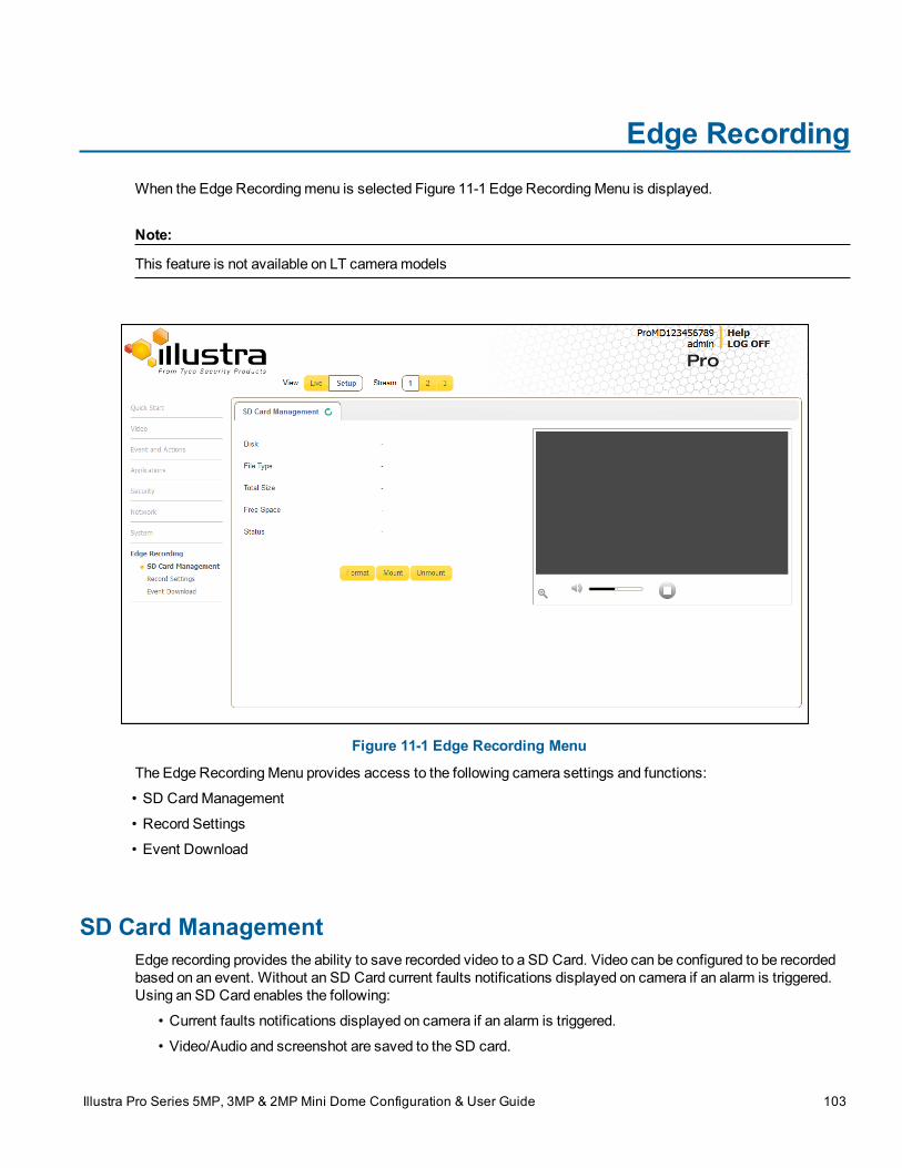
Edge RecordingWhen the Edge Recordingmenu is selected Figure 11-1 Edge RecordingMenu is displayed.
Note:
This feature is not available on LT cameramodels
Figure 11-1 Edge Recording Menu
The Edge RecordingMenu provides access to the following camera settings and functions:
• SD CardManagement
• Record Settings
• Event Download
SD Card ManagementEdge recording provides the ability to save recorded video to a SD Card. Video can be configured to be recordedbased on an event. Without an SD Card current faults notifications displayed on camera if an alarm is triggered.Using an SD Card enables the following:
• Current faults notifications displayed on camera if an alarm is triggered.
• Video/Audio and screenshot are saved to the SD card.
Illustra Pro Series 5MP, 3MP & 2MP Mini Dome Configuration & User Guide 103
SD Card Management
• SMTP notifications can be sent.
• FTP uploads of video can be sent.
• Audio can be played via the Audio Out port.
Note:
This feature is not available on a LT cameramodel.
Inserting the SD CardWhen inserting an SD card it is essential that the camera is rebooted. The camera is mounted and unmountedthrough theWebUser Interface.
Note:
Refer to the Quick ReferenceGuide supplied with the product for details on how to remove the housing assemblyand gain access to the camera.
microSD Cards are not supported by the LT cameramodels.
Procedure 11-1 Insert the SD Card by powering down the Camera
Step Action
1 Turn off the camera by disconnecting the power supply.
2 Insert the SD card into the camera.
3 Reconnect the power supply and power up the camera.
- End -
Procedure 11-2 Mount the SD Card via the Web User Interface to reboot the Camera
Step Action
1 Insert theMicroSD card into the camera.
2 Select Setup on theWebUser Interface banner to display the setupmenus.
3 Select SD Card Managementmenu from theEdge Recordingmenu.4 SelectMount.
- End -
Removing the MicroSD CardIf at any stage you need to remove theMicroSD card from the camera one of the following two procedures shouldbe used:
• Remove the SD Card by powering down the camera - Use this procedure if you don’t have accessto theWebUser Interface and are unable to unmount theMicroSD card before removal.
104
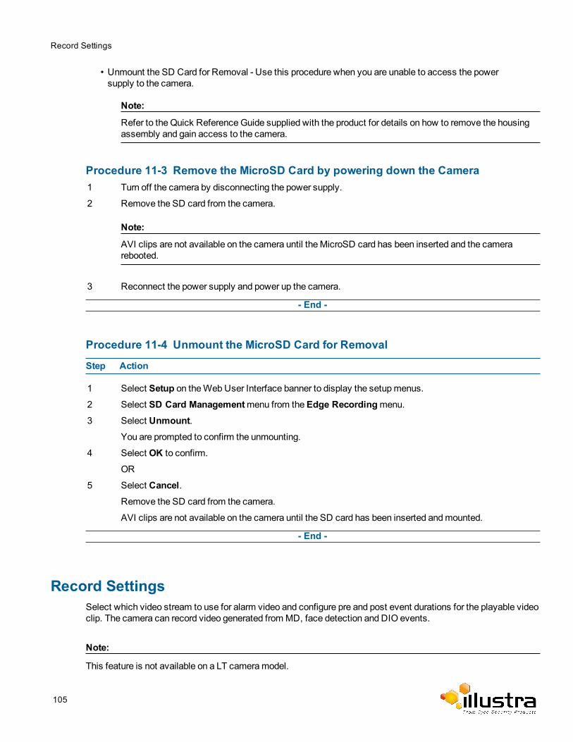
Record Settings
• Unmount the SD Card for Removal - Use this procedure when you are unable to access the powersupply to the camera.
Note:
Refer to the Quick ReferenceGuide supplied with the product for details on how to remove the housingassembly and gain access to the camera.
Procedure 11-3 Remove the MicroSD Card by powering down the Camera1 Turn off the camera by disconnecting the power supply.
2 Remove the SD card from the camera.
Note:
AVI clips are not available on the camera until theMicroSD card has been inserted and the camerarebooted.
3 Reconnect the power supply and power up the camera.
- End -
Procedure 11-4 Unmount the MicroSD Card for Removal
Step Action
1 Select Setup on theWebUser Interface banner to display the setupmenus.
2 Select SD Card Managementmenu from theEdge Recordingmenu.3 Select Unmount.
You are prompted to confirm the unmounting.
4 Select OK to confirm.
OR
5 Select Cancel.Remove the SD card from the camera.
AVI clips are not available on the camera until the SD card has been inserted andmounted.
- End -
Record SettingsSelect which video stream to use for alarm video and configure pre and post event durations for the playable videoclip. The camera can record video generated fromMD, face detection and DIO events.
Note:
This feature is not available on a LT cameramodel.
105
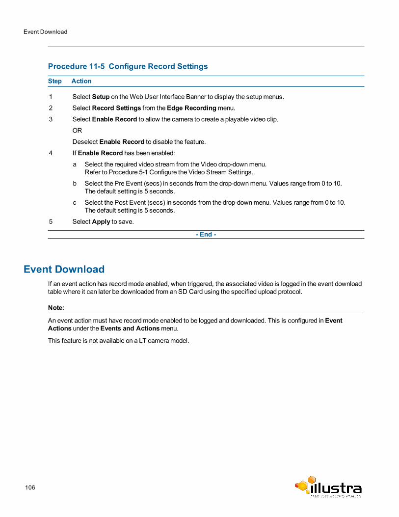
Event Download
Procedure 11-5 Configure Record Settings
Step Action
1 Select Setup on theWebUser Interface Banner to display the setupmenus.
2 Select Record Settings from theEdge Recordingmenu.3 Select Enable Record to allow the camera to create a playable video clip.
OR
Deselect Enable Record to disable the feature.4 If Enable Record has been enabled:
a Select the required video stream from the Video drop-downmenu.Refer to Procedure 5-1 Configure the Video Stream Settings.
b Select the Pre Event (secs) in seconds from the drop-downmenu. Values range from 0 to 10.The default setting is 5 seconds.
c Select the Post Event (secs) in seconds from the drop-downmenu. Values range from 0 to 10.The default setting is 5 seconds.
5 Select Apply to save.
- End -
Event DownloadIf an event action has recordmode enabled, when triggered, the associated video is logged in the event downloadtable where it can later be downloaded from an SD Card using the specified upload protocol.
Note:
An event actionmust have recordmode enabled to be logged and downloaded. This is configured inEventActions under theEvents and Actionsmenu.
This feature is not available on a LT cameramodel.
106
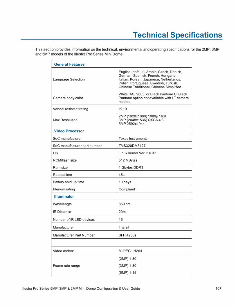
Technical SpecificationsThis section provides information on the technical, environmental and operating specifications for the 2MP, 3MPand 5MP models of the Illustra Pro Series Mini Dome.
General Features
Language Selection
English (default), Arabic, Czech, Danish,German, Spanish, French, Hungarian,Italian, Korean, Japanese, Netherlands,Polish, Portuguese, Swedish, Turkish,Chinese Traditional, Chinese Simplified.
Camera body colorWhite RAL 9003, or Black Pantone C. BlackPantone option not available with LT cameramodels.
Vandal resistant rating IK 10
Max Resolution2MP (1920x1080) 1080p 16:93MP (2048x1536) QXGA 4:35MP 2592x1944
Video Processor
SoC manufacturer Texas Instruments
SoC manufacturer part number TMS320DM8127
OS Linux kernel Ver. 2.6.37
ROM/flash size 512 MBytes
Ram size 1 Gbytes DDR3
Reboot time 45s
Battery hold up time 10 days
Plenum rating Compliant
Illuminator
Wavelength 850 nm
IR Distance 20m
Number of IR LED devices 16
Manufacturer Intersil
Manufacturer Part Number SFH 4258s
Video codecs MJPEG - H264
Frame rate range
(2MP) 1-30
(3MP) 1-30
(5MP) 1-15
Illustra Pro Series 5MP, 3MP & 2MP Mini Dome Configuration & User Guide 107
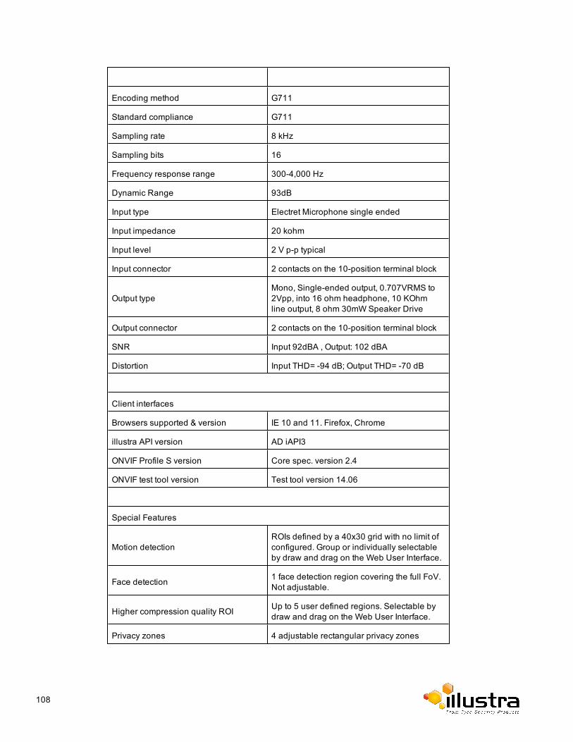
Encoding method G711
Standard compliance G711
Sampling rate 8 kHz
Sampling bits 16
Frequency response range 300-4,000 Hz
Dynamic Range 93dB
Input type Electret Microphone single ended
Input impedance 20 kohm
Input level 2 V p-p typical
Input connector 2 contacts on the 10-position terminal block
Output typeMono, Single-ended output, 0.707VRMS to2Vpp, into 16 ohm headphone, 10 KOhmline output, 8 ohm 30mWSpeaker Drive
Output connector 2 contacts on the 10-position terminal block
SNR Input 92dBA , Output: 102 dBA
Distortion Input THD= -94 dB; Output THD= -70 dB
Client interfaces
Browsers supported & version IE 10 and 11. Firefox, Chrome
illustra API version AD iAPI3
ONVIF Profile S version Core spec. version 2.4
ONVIF test tool version Test tool version 14.06
Special Features
Motion detectionROIs defined by a 40x30 grid with no limit ofconfigured. Group or individually selectableby draw and drag on the Web User Interface.
Face detection 1 face detection region covering the full FoV.Not adjustable.
Higher compression quality ROI Up to 5 user defined regions. Selectable bydraw and drag on the Web User Interface.
Privacy zones 4 adjustable rectangular privacy zones
108
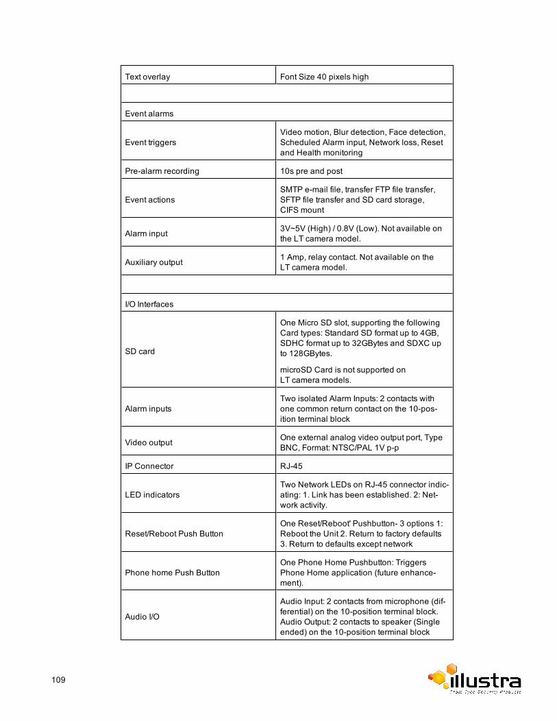
Text overlay Font Size 40 pixels high
Event alarms
Event triggersVideo motion, Blur detection, Face detection,Scheduled Alarm input, Network loss, Resetand Health monitoring
Pre-alarm recording 10s pre and post
Event actionsSMTP e-mail file, transfer FTP file transfer,SFTP file transfer and SD card storage,CIFS mount
Alarm input 3V~5V (High) / 0.8V (Low). Not available onthe LT camera model.
Auxiliary output 1 Amp, relay contact. Not available on theLT camera model.
I/O Interfaces
SD card
One Micro SD slot, supporting the followingCard types: Standard SD format up to 4GB,SDHC format up to 32GBytes and SDXC upto 128GBytes.
microSD Card is not supported onLT camera models.
Alarm inputsTwo isolated Alarm Inputs: 2 contacts withone common return contact on the 10-pos-ition terminal block
Video output One external analog video output port, TypeBNC, Format: NTSC/PAL 1V p-p
IP Connector RJ-45
LED indicatorsTwo Network LEDs on RJ-45 connector indic-ating: 1. Link has been established. 2: Net-work activity.
Reset/Reboot Push ButtonOne Reset/Reboot' Pushbutton- 3 options 1:Reboot the Unit 2. Return to factory defaults3. Return to defaults except network
Phone home Push ButtonOne Phone Home Pushbutton: TriggersPhone Home application (future enhance-ment).
Audio I/O
Audio Input: 2 contacts from microphone (dif-ferential) on the 10-position terminal block.Audio Output: 2 contacts to speaker (Singleended) on the 10-position terminal block
109
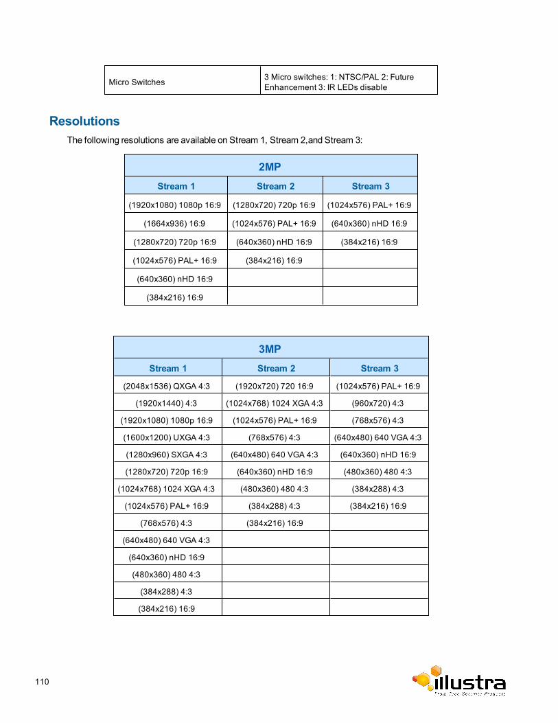
Micro Switches 3 Micro switches: 1: NTSC/PAL 2: FutureEnhancement 3: IR LEDs disable
ResolutionsThe following resolutions are available on Stream 1, Stream 2,and Stream 3:
2MPStream 1 Stream 2 Stream 3
(1920x1080) 1080p 16:9 (1280x720) 720p 16:9 (1024x576) PAL+ 16:9
(1664x936) 16:9 (1024x576) PAL+ 16:9 (640x360) nHD 16:9
(1280x720) 720p 16:9 (640x360) nHD 16:9 (384x216) 16:9
(1024x576) PAL+ 16:9 (384x216) 16:9
(640x360) nHD 16:9
(384x216) 16:9
3MPStream 1 Stream 2 Stream 3
(2048x1536) QXGA 4:3 (1920x720) 720 16:9 (1024x576) PAL+ 16:9
(1920x1440) 4:3 (1024x768) 1024 XGA 4:3 (960x720) 4:3
(1920x1080) 1080p 16:9 (1024x576) PAL+ 16:9 (768x576) 4:3
(1600x1200) UXGA 4:3 (768x576) 4:3 (640x480) 640 VGA 4:3
(1280x960) SXGA 4:3 (640x480) 640 VGA 4:3 (640x360) nHD 16:9
(1280x720) 720p 16:9 (640x360) nHD 16:9 (480x360) 480 4:3
(1024x768) 1024 XGA 4:3 (480x360) 480 4:3 (384x288) 4:3
(1024x576) PAL+ 16:9 (384x288) 4:3 (384x216) 16:9
(768x576) 4:3 (384x216) 16:9
(640x480) 640 VGA 4:3
(640x360) nHD 16:9
(480x360) 480 4:3
(384x288) 4:3
(384x216) 16:9
110
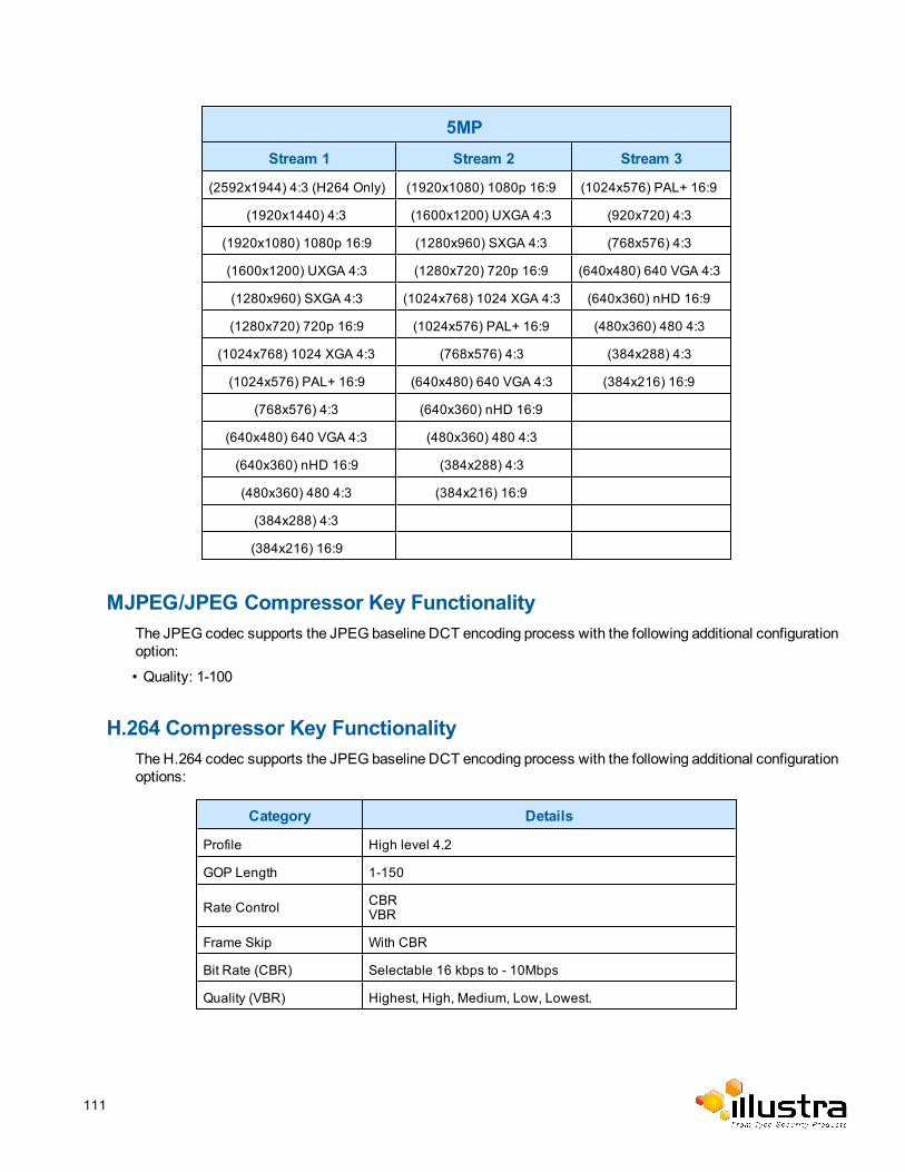
5MPStream 1 Stream 2 Stream 3
(2592x1944) 4:3 (H264 Only) (1920x1080) 1080p 16:9 (1024x576) PAL+ 16:9
(1920x1440) 4:3 (1600x1200) UXGA 4:3 (920x720) 4:3
(1920x1080) 1080p 16:9 (1280x960) SXGA 4:3 (768x576) 4:3
(1600x1200) UXGA 4:3 (1280x720) 720p 16:9 (640x480) 640 VGA 4:3
(1280x960) SXGA 4:3 (1024x768) 1024 XGA 4:3 (640x360) nHD 16:9
(1280x720) 720p 16:9 (1024x576) PAL+ 16:9 (480x360) 480 4:3
(1024x768) 1024 XGA 4:3 (768x576) 4:3 (384x288) 4:3
(1024x576) PAL+ 16:9 (640x480) 640 VGA 4:3 (384x216) 16:9
(768x576) 4:3 (640x360) nHD 16:9
(640x480) 640 VGA 4:3 (480x360) 480 4:3
(640x360) nHD 16:9 (384x288) 4:3
(480x360) 480 4:3 (384x216) 16:9
(384x288) 4:3
(384x216) 16:9
MJPEG/JPEG Compressor Key FunctionalityThe JPEG codec supports the JPEG baseline DCT encoding process with the following additional configurationoption:
• Quality: 1-100
H.264 Compressor Key FunctionalityThe H.264 codec supports the JPEG baseline DCT encoding process with the following additional configurationoptions:
Category Details
Profile High level 4.2
GOP Length 1-150
Rate Control CBRVBR
Frame Skip With CBR
Bit Rate (CBR) Selectable 16 kbps to - 10Mbps
Quality (VBR) Highest, High, Medium, Low, Lowest.
111
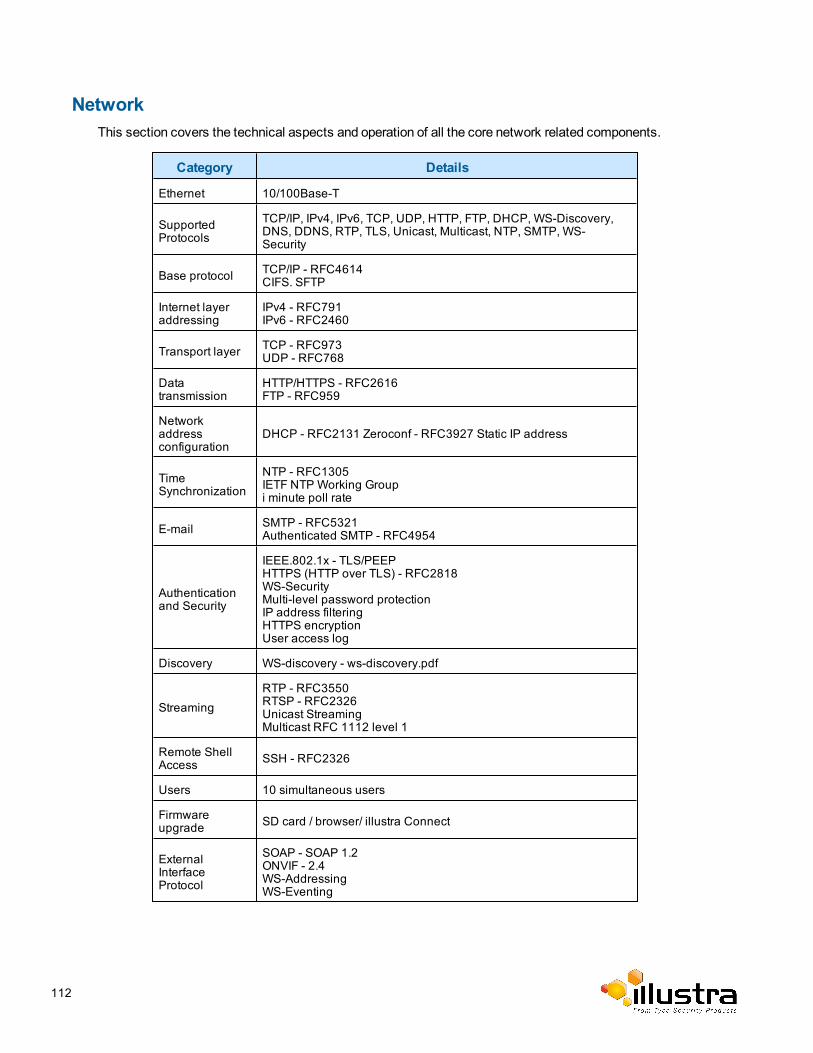
NetworkThis section covers the technical aspects and operation of all the core network related components.
Category Details
Ethernet 10/100Base-T
SupportedProtocols
TCP/IP, IPv4, IPv6, TCP, UDP, HTTP, FTP, DHCP, WS-Discovery,DNS, DDNS, RTP, TLS, Unicast, Multicast, NTP, SMTP, WS-Security
Base protocol TCP/IP - RFC4614CIFS. SFTP
Internet layeraddressing
IPv4 - RFC791IPv6 - RFC2460
Transport layer TCP - RFC973UDP - RFC768
Datatransmission
HTTP/HTTPS - RFC2616FTP - RFC959
Networkaddressconfiguration
DHCP - RFC2131 Zeroconf - RFC3927 Static IP address
TimeSynchronization
NTP - RFC1305IETF NTP Working Groupi minute poll rate
E-mail SMTP - RFC5321Authenticated SMTP - RFC4954
Authenticationand Security
IEEE.802.1x - TLS/PEEPHTTPS (HTTP over TLS) - RFC2818WS-SecurityMulti-level password protectionIP address filteringHTTPS encryptionUser access log
Discovery WS-discovery - ws-discovery.pdf
StreamingRTP - RFC3550RTSP - RFC2326Unicast StreamingMulticast RFC 1112 level 1
Remote ShellAccess SSH - RFC2326
Users 10 simultaneous users
Firmwareupgrade SD card / browser/ illustra Connect
ExternalInterfaceProtocol
SOAP - SOAP 1.2ONVIF - 2.4WS-AddressingWS-Eventing
112
Base Protocol and Underlying Layers• The camera is an IP camera compatible with TCP/IP protocol.
• The camera supports both IPv4 and IPv6, running either in single stack mode or dual stack mode(supporting both IP versions at the same time).
• TCP is used for two way communication and UDP will be used for broadcasting protocols.
• HTTP is used for the ONVIF protocol as transport mechanism for SOAP calls.
• FTP can be used to push alarm buffer video clips to a specified remote FTP server. The camera can useanonymous FTP or a specified username and password. There is no incoming FTP service.
IP multicast RFC 1112 level 1 support for sending but not receivingmulticast IP datagrams to a group ofinterested receivers in single transmissions is supported for audio, video andmetadata stream types. Thestreams can be controlled using the twomethods described below:
1 A client can request amulticast stream using RTSP. When the client requests a stream the server willrespond with amulticast address in the ‘c=’ field of the describe response (RFC 4566). The client willthen respond with a Setup request with the Transport Type set to multicast, the device shall stop sendingpackets for amulticast configuration when nomore RTSP sessions are using the samemulticast con-figuration.
2 An RTP multicast UDP stream can be started by anONVIF ‘StartMulticastStreaming’ request with aspecifiedmedia profile. Streaming continues until ‘StopMulticastStreaming’ is called for the same profile
Multicast RTSP sessions support the same authenticationmethods as unicast RTSP sessions.
Network Address Configuration• DHCP (Dynamic Host Configuration Protocol)will be enabled by default on the camera. During theboot process, the camera will attempt to acquire a network address via DHCP. The DHCP client will beconfigured to do 3 attempts with a 20 second timeout.
• Static IP can be used if the camera cannot be found on the network using DHCP. In this mode, a staticIP address, subnet mask, default router and a primary and secondary DNS server can be configured.This will be used by the camera when turned on. It is possible to assign a static IPv4 address while stillallowing the IPv6 addressing to be Link Local (automatically assigned).
• Dynamic DNS or DDNS Dynamic Domain Name System is supported for updating, in real time achanging IP address on the Internet to provide a persistent domain name for a resource that may changelocation on the network. RFC 2136 Dynamic Updates in the Domain Name System. In this situation thecamera talks only to the DHCP server and the DHCP server is responsible for updating the DNS server.The camera sends its hostname to the DHCP server when requesting a new lease and the DHCPserver updates the DNS records accordingly. This is suitable for an intranet style configuration wherethere is an internal DHCP and DNS service and the user wants only to access their camera within theirown network.
By default, whenmaking a DHCP request the camera will transmit its hostname as part of the DHCP request.This option is not user configurable. The cameras hostnamematches the configurable parameter “camera name”on theWebUser Interface. Any DHCP request will contain the cameras hostname for use of the DHCP server toforward to an appropriate DNS server.
Network Name ResolutionThe camera uses DNS protocol to resolve network names. DNS server address will be acquired via DHCP ormanually set for static IP configuration. Camera configuration supports symbolic names for all remote end-points
113
(except DNS servers) but in this mode will depend on a working and correctly configured remote DNS server.
EmailThe camera can send email alerts via SMTP to one specifiedmailbox using a specified SMTP server. Support isprovided for basic authenticated SMTP using username and password for login on the SMTP server.
Time Synchronization and ConfigurationThe camera supports NTP for time synchronization. The NTP server will have to be configured by the user.Alternatively, time can bemanually configured via theWebUser Interface or ONVIF.
CIFS MountingThe camera supports the CIFS protocol for mounting a windows file share. This is configured with a network path,domain name and password. It can be used to store video associated with alarms.
Remote Shell AccessFor security reason, remote shell access is limited exclusively to Tyco Security Products Level 3 TechnicalSupport. This function is not available to the end-user.
It is recommended to keep SSH Enable disabled. This function should only be enabled this when it is requestedby Tyco Security Products Level 3 Technical Support.
Authentication and Security• HTTPS (HTTP over TLS) is used for theWebUser Interface. HTTP connections to the camera IP willautomatically be redirected to the HTTPS login page.
• The camera will automatically create a SSL certificate file to use for HTTPS. It is possible to upload acustom SSL certificate if validation is desired.
• TheONVIF service uses WS-Security Username Token Digest.
FirewallThe camera will provide a firewall, which is disabled by default. The firewall will be able to block ICMP and allowRP filtering and SYN Cookie Verification.The firewall will offer the ability to block selected IP or MAC addressesand allow access exclusively to selected IP andMAC addresses.
Note:
Using the “Deny all” mode, could result in amiss-configuration and require resetting the camera via the physicalreset button.
DiscoveryThe product supports WS-Discovery for discovery purpose.
114
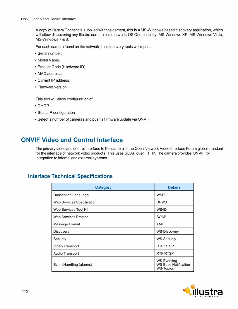
ONVIF Video and Control Interface
A copy of Illustra Connect is supplied with the camera, this is aMS-Windows based discovery application, whichwill allow discovering any Illustra camera on a network; OS Compatibility: MS-Windows XP, MS-Windows Vista,MS-Windows 7 & 8.
For each camera found on the network, the discovery tools will report:
• Serial number.
• Model Name.
• Product Code (Hardware ID).
• MAC address.
• Current IP address.
• Firmware version.
This tool will allow configuration of:
• DHCP
• Static IP configuration
• Select a number of cameras and push a firmware update via ONVIF
ONVIF Video and Control InterfaceThe primary video and control interface to the camera is the Open Network Video Interface Forum global standardfor the interface of network video products. This uses SOAP over HTTP. The camera provides ONVIF forintegration to internal and external systems.
Interface Technical Specifications
Category Details
Description Language WSDL
Web Services Specification DPWS
Web Services Tool Kit WS4D
Web Services Protocol SOAP
Message Format XML
Discovery WS-Discovery
Security WS-Security
Video Transport RTP/RTSP
Audio Transport RTP/RTSP
Event Handling (alarms)WS-EventingWS-Base NotificationWS-Topics
115
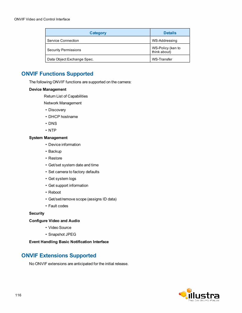
ONVIF Video and Control Interface
Category Details
Service Connection WS-Addressing
Security Permissions WS-Policy (ken tothink about)
Data Object Exchange Spec. WS-Transfer
ONVIF Functions SupportedThe following ONVIF functions are supported on the camera:
Device ManagementReturn List of Capabilities
Network Management
• Discovery
• DHCP hostname
• DNS
• NTP
System Management• Device information
• Backup
• Restore
• Get/set system date and time
• Set camera to factory defaults
• Get system logs
• Get support information
• Reboot
• Get/set/remove scope (assigns ID data)
• Fault codes
Security
Configure Video and Audio• Video Source
• Snapshot JPEG
Event Handling Basic Notification Interface
ONVIF Extensions SupportedNoONVIF extensions are anticipated for the initial release.
116

ONVIF Video and Control Interface
ONVIF Functions Not SupportedThe following ONVIF functions are not supported on the camera:
• Audio configuration
• Video compression standards other than H.264, andMJPEG.
• PTZ control including ePTZ, presets and home position.
117
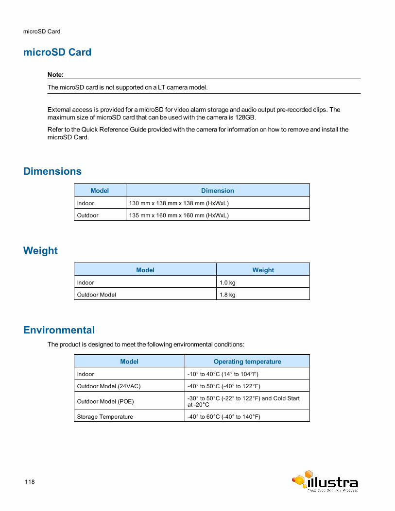
microSD Card
microSD Card
Note:
ThemicroSD card is not supported on a LT cameramodel.
External access is provided for amicroSD for video alarm storage and audio output pre-recorded clips. Themaximum size of microSD card that can be used with the camera is 128GB.
Refer to the Quick ReferenceGuide provided with the camera for information on how to remove and install themicroSD Card.
Dimensions
Model Dimension
Indoor 130 mm x 138 mm x 138 mm (HxWxL)
Outdoor 135 mm x 160 mm x 160 mm (HxWxL)
Weight
Model Weight
Indoor 1.0 kg
Outdoor Model 1.8 kg
EnvironmentalThe product is designed tomeet the following environmental conditions:
Model Operating temperature
Indoor -10° to 40°C (14° to 104°F)
Outdoor Model (24VAC) -40° to 50°C (-40° to 122°F)
Outdoor Model (POE) -30° to 50°C (-22° to 122°F) and Cold Startat -20°C
Storage Temperature -40° to 60°C (-40° to 140°F)
118
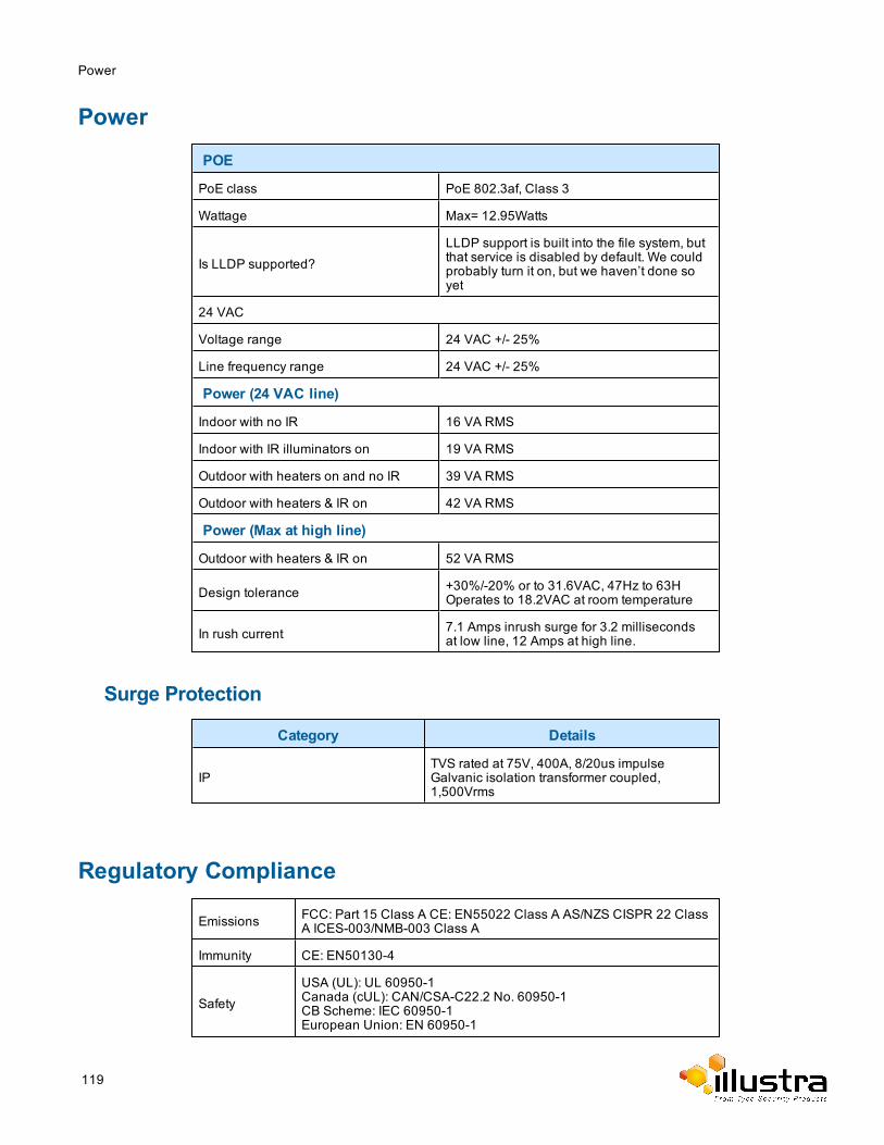
Power
Power
POE
PoE class PoE 802.3af, Class 3
Wattage Max= 12.95Watts
Is LLDP supported?LLDP support is built into the file system, butthat service is disabled by default. We couldprobably turn it on, but we haven’t done soyet
24 VAC
Voltage range 24 VAC +/- 25%
Line frequency range 24 VAC +/- 25%
Power (24 VAC line)
Indoor with no IR 16 VA RMS
Indoor with IR illuminators on 19 VA RMS
Outdoor with heaters on and no IR 39 VA RMS
Outdoor with heaters & IR on 42 VA RMS
Power (Max at high line)
Outdoor with heaters & IR on 52 VA RMS
Design tolerance +30%/-20% or to 31.6VAC, 47Hz to 63HOperates to 18.2VAC at room temperature
In rush current 7.1 Amps inrush surge for 3.2 millisecondsat low line, 12 Amps at high line.
Surge Protection
Category Details
IPTVS rated at 75V, 400A, 8/20us impulseGalvanic isolation transformer coupled,1,500Vrms
Regulatory Compliance
Emissions FCC: Part 15 Class A CE: EN55022 Class A AS/NZS CISPR 22 ClassA ICES-003/NMB-003 Class A
Immunity CE: EN50130-4
SafetyUSA (UL): UL 60950-1Canada (cUL): CAN/CSA-C22.2 No. 60950-1CB Scheme: IEC 60950-1European Union: EN 60950-1
119
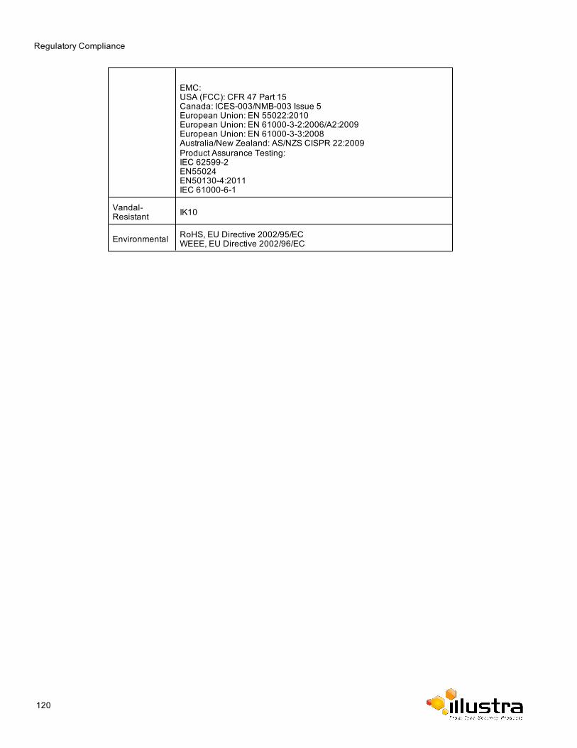
Regulatory Compliance
EMC:USA (FCC): CFR 47 Part 15Canada: ICES-003/NMB-003 Issue 5European Union: EN 55022:2010European Union: EN 61000-3-2:2006/A2:2009European Union: EN 61000-3-3:2008Australia/New Zealand: AS/NZS CISPR 22:2009Product Assurance Testing:IEC 62599-2EN55024EN50130-4:2011IEC 61000-6-1
Vandal-Resistant IK10
Environmental RoHS, EU Directive 2002/95/ECWEEE, EU Directive 2002/96/EC
120
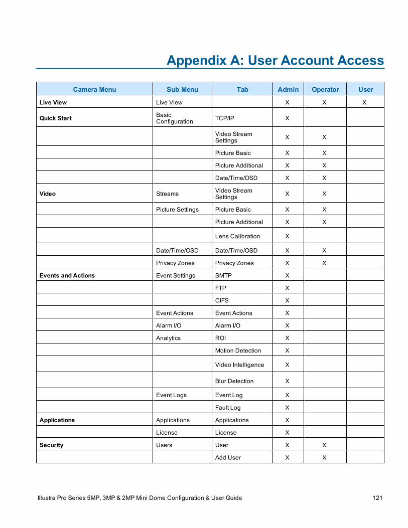
Appendix A: User Account Access
Camera Menu Sub Menu Tab Admin Operator User
Live View Live View X X X
Quick Start BasicConfiguration TCP/IP X
Video StreamSettings X X
Picture Basic X X
Picture Additional X X
Date/Time/OSD X X
Video Streams Video StreamSettings X X
Picture Settings Picture Basic X X
Picture Additional X X
Lens Calibration X
Date/Time/OSD Date/Time/OSD X X
Privacy Zones Privacy Zones X X
Events and Actions Event Settings SMTP X
FTP X
CIFS X
Event Actions Event Actions X
Alarm I/O Alarm I/O X
Analytics ROI X
Motion Detection X
Video Intelligence X
Blur Detection X
Event Logs Event Log X
Fault Log X
Applications Applications Applications X
License License X
Security Users User X X
Add User X X
Illustra Pro Series 5MP, 3MP & 2MP Mini Dome Configuration & User Guide 121
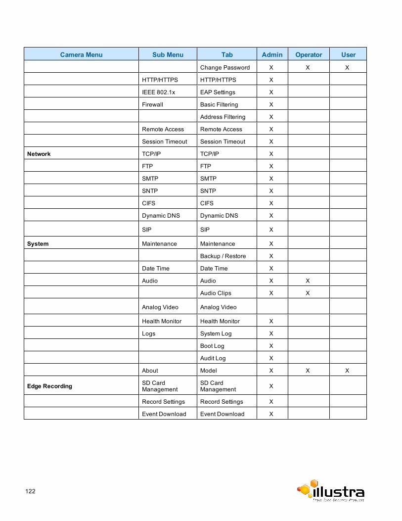
Camera Menu Sub Menu Tab Admin Operator User
Change Password X X X
HTTP/HTTPS HTTP/HTTPS X
IEEE 802.1x EAP Settings X
Firewall Basic Filtering X
Address Filtering X
Remote Access Remote Access X
Session Timeout Session Timeout X
Network TCP/IP TCP/IP X
FTP FTP X
SMTP SMTP X
SNTP SNTP X
CIFS CIFS X
Dynamic DNS Dynamic DNS X
SIP SIP X
System Maintenance Maintenance X
Backup / Restore X
Date Time Date Time X
Audio Audio X X
Audio Clips X X
Analog Video Analog Video
Health Monitor Health Monitor X
Logs System Log X
Boot Log X
Audit Log X
About Model X X X
Edge Recording SD CardManagement
SD CardManagement X
Record Settings Record Settings X
Event Download Event Download X
122
Appendix B - Using Media Player to View RTSPStreaming
Note:
This appendix is provided for user instruction only. Tyco Security Products does not support or is not responsiblefor any error caused during the use of third party software used for RTSP playback.
Viewing RTSP Stream through Media PlayerYou can useMedia Player to view live video and audio in real time from the camera.
1 SelectMedia thenOpen Network Stream.
2 Enter the IP address of the camera stream in theNetwork URL text box in the following format to viewStream 1 and 2:
• Stream 1: rtsp://<ip address>:554/StreamId=1• Stream 2: rtsp://<ip address>:554/StreamId=2For example: rtsp://192.168.1.168:554/StreamId=1
3 Select Play.The live video stream is displayed.
- End -
Illustra Pro Series 5MP, 3MP & 2MP Mini Dome Configuration & User Guide 123
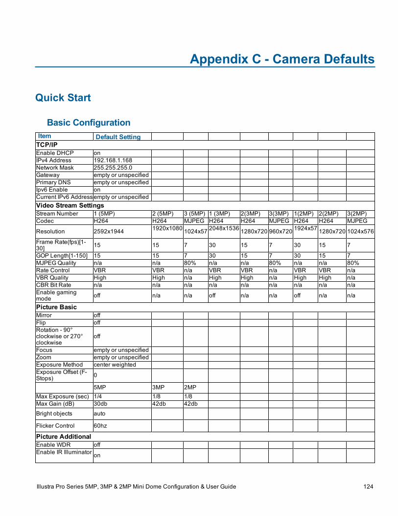
Appendix C - Camera Defaults
Quick Start
Basic ConfigurationItem Default SettingTCP/IPEnable DHCP onIPv4 Address 192.168.1.168Network Mask 255.255.255.0Gateway empty or unspecifiedPrimary DNS empty or unspecifiedIpv6 Enable onCurrent IPv6 Address empty or unspecifiedVideo Stream SettingsStream Number 1 (5MP) 2 (5MP) 3 (5MP) 1 (3MP) 2(3MP) 3(3MP) 1(2MP) 2(2MP) 3(2MP)Codec H264 H264 MJPEG H264 H264 MJPEG H264 H264 MJPEG
Resolution 2592x1944 1920x1080 1024x57 2048x1536 1280x720 960x720 1924x57 1280x720 1024x576
Frame Rate(fps)[1-30] 15 15 7 30 15 7 30 15 7
GOP Length[1-150] 15 15 7 30 15 7 30 15 7MJPEGQuality n/a n/a 80% n/a n/a 80% n/a n/a 80%Rate Control VBR VBR n/a VBR VBR n/a VBR VBR n/aVBR Quality High High n/a High High n/a High High n/aCBR Bit Rate n/a n/a n/a n/a n/a n/a n/a n/a n/aEnable gamingmode off n/a n/a off n/a n/a off n/a n/a
Picture BasicMirror offFlip offRotation - 90°clockwise or 270°clockwise
off
Focus empty or unspecifiedZoom empty or unspecifiedExposure Method center weightedExposure Offset (F-Stops) 0
5MP 3MP 2MPMax Exposure (sec) 1/4 1/8 1/8Max Gain (dB) 30db 42db 42db
Bright objects auto
Flicker Control 60hz
Picture AdditionalEnable WDR offEnable IR Illuminator on
Illustra Pro Series 5MP, 3MP & 2MP Mini Dome Configuration & User Guide 124
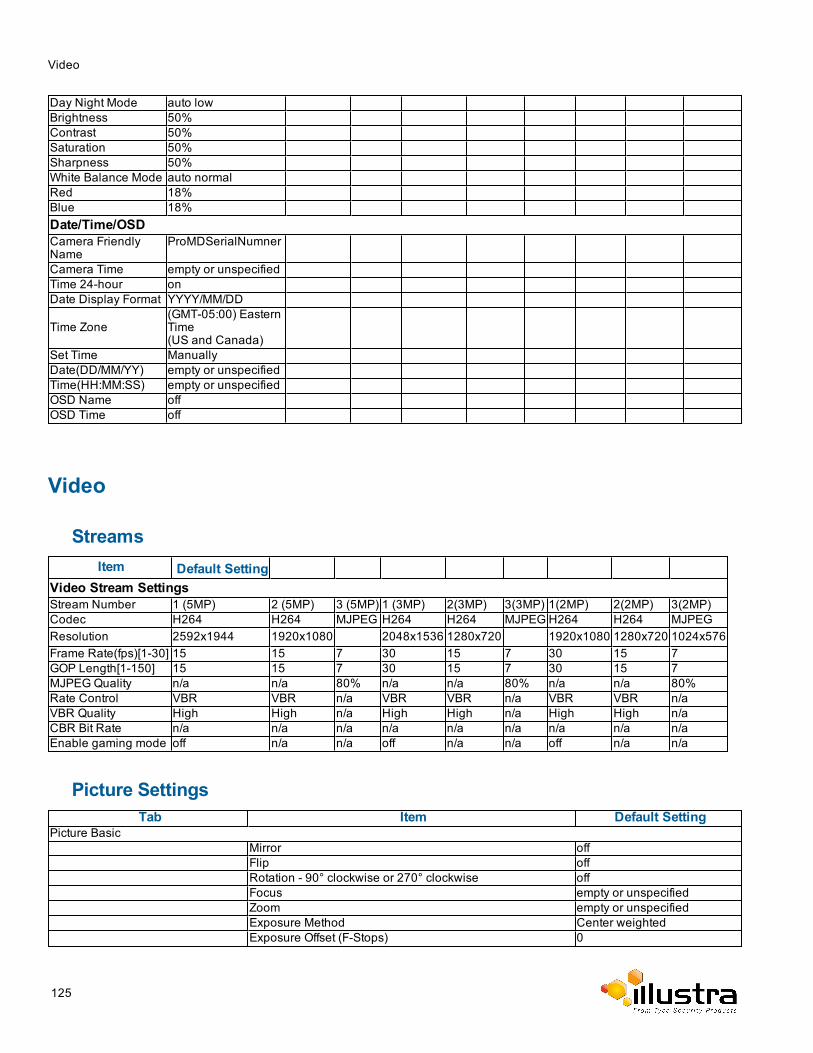
Video
Day Night Mode auto lowBrightness 50%Contrast 50%Saturation 50%Sharpness 50%White Balance Mode auto normalRed 18%Blue 18%Date/Time/OSDCamera FriendlyName
ProMDSerialNumner
Camera Time empty or unspecifiedTime 24-hour onDate Display Format YYYY/MM/DD
Time Zone(GMT-05:00) EasternTime(US and Canada)
Set Time ManuallyDate(DD/MM/YY) empty or unspecifiedTime(HH:MM:SS) empty or unspecifiedOSD Name offOSD Time off
Video
StreamsItem Default Setting
Video Stream SettingsStream Number 1 (5MP) 2 (5MP) 3 (5MP) 1 (3MP) 2(3MP) 3(3MP) 1(2MP) 2(2MP) 3(2MP)Codec H264 H264 MJPEG H264 H264 MJPEG H264 H264 MJPEGResolution 2592x1944 1920x1080 2048x1536 1280x720 1920x1080 1280x720 1024x576Frame Rate(fps)[1-30] 15 15 7 30 15 7 30 15 7GOP Length[1-150] 15 15 7 30 15 7 30 15 7MJPEGQuality n/a n/a 80% n/a n/a 80% n/a n/a 80%Rate Control VBR VBR n/a VBR VBR n/a VBR VBR n/aVBR Quality High High n/a High High n/a High High n/aCBR Bit Rate n/a n/a n/a n/a n/a n/a n/a n/a n/aEnable gaming mode off n/a n/a off n/a n/a off n/a n/a
Picture SettingsTab Item Default Setting
Picture BasicMirror offFlip offRotation - 90° clockwise or 270° clockwise offFocus empty or unspecifiedZoom empty or unspecifiedExposure Method Center weightedExposure Offset (F-Stops) 0
125
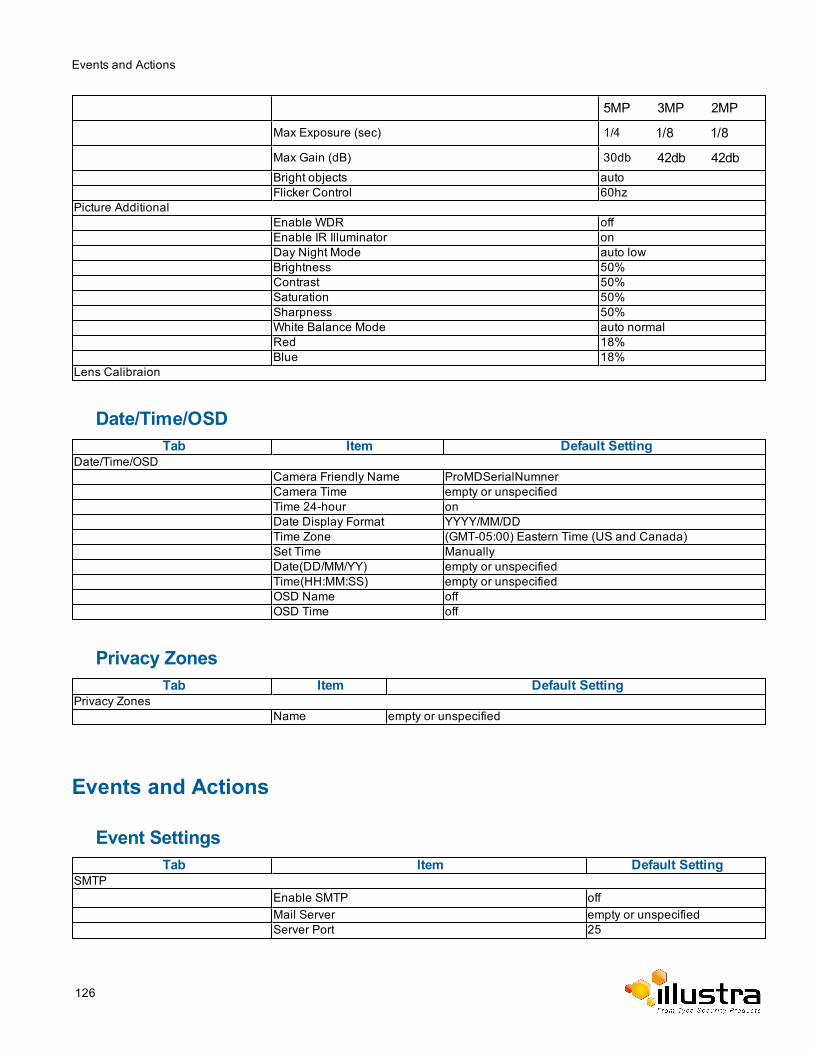
Events and Actions
5MP 3MP 2MP
Max Exposure (sec) 1/4 1/8 1/8
Max Gain (dB) 30db 42db 42dbBright objects autoFlicker Control 60hz
Picture AdditionalEnable WDR offEnable IR Illuminator onDay Night Mode auto lowBrightness 50%Contrast 50%Saturation 50%Sharpness 50%White Balance Mode auto normalRed 18%Blue 18%
Lens Calibraion
Date/Time/OSDTab Item Default Setting
Date/Time/OSDCamera Friendly Name ProMDSerialNumnerCamera Time empty or unspecifiedTime 24-hour onDate Display Format YYYY/MM/DDTime Zone (GMT-05:00) Eastern Time (US and Canada)Set Time ManuallyDate(DD/MM/YY) empty or unspecifiedTime(HH:MM:SS) empty or unspecifiedOSD Name offOSD Time off
Privacy ZonesTab Item Default Setting
Privacy ZonesName empty or unspecified
Events and Actions
Event SettingsTab Item Default Setting
SMTPEnable SMTP offMail Server empty or unspecifiedServer Port 25
126
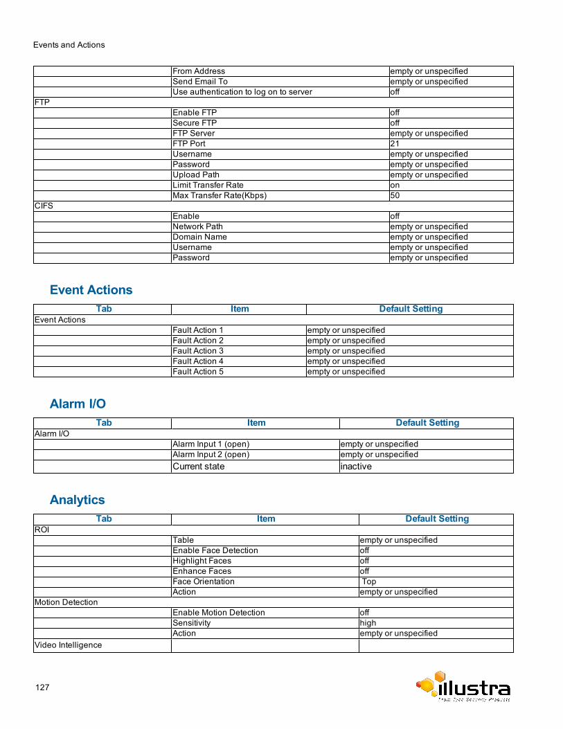
Events and Actions
From Address empty or unspecifiedSend Email To empty or unspecifiedUse authentication to log on to server off
FTPEnable FTP offSecure FTP offFTP Server empty or unspecifiedFTP Port 21Username empty or unspecifiedPassword empty or unspecifiedUpload Path empty or unspecifiedLimit Transfer Rate onMax Transfer Rate(Kbps) 50
CIFSEnable offNetwork Path empty or unspecifiedDomain Name empty or unspecifiedUsername empty or unspecifiedPassword empty or unspecified
Event ActionsTab Item Default Setting
Event ActionsFault Action 1 empty or unspecifiedFault Action 2 empty or unspecifiedFault Action 3 empty or unspecifiedFault Action 4 empty or unspecifiedFault Action 5 empty or unspecified
Alarm I/OTab Item Default Setting
Alarm I/OAlarm Input 1 (open) empty or unspecifiedAlarm Input 2 (open) empty or unspecifiedCurrent state inactive
AnalyticsTab Item Default Setting
ROITable empty or unspecifiedEnable Face Detection offHighlight Faces offEnhance Faces offFace Orientation TopAction empty or unspecified
Motion DetectionEnable Motion Detection offSensitivity highAction empty or unspecified
Video Intelligence
127
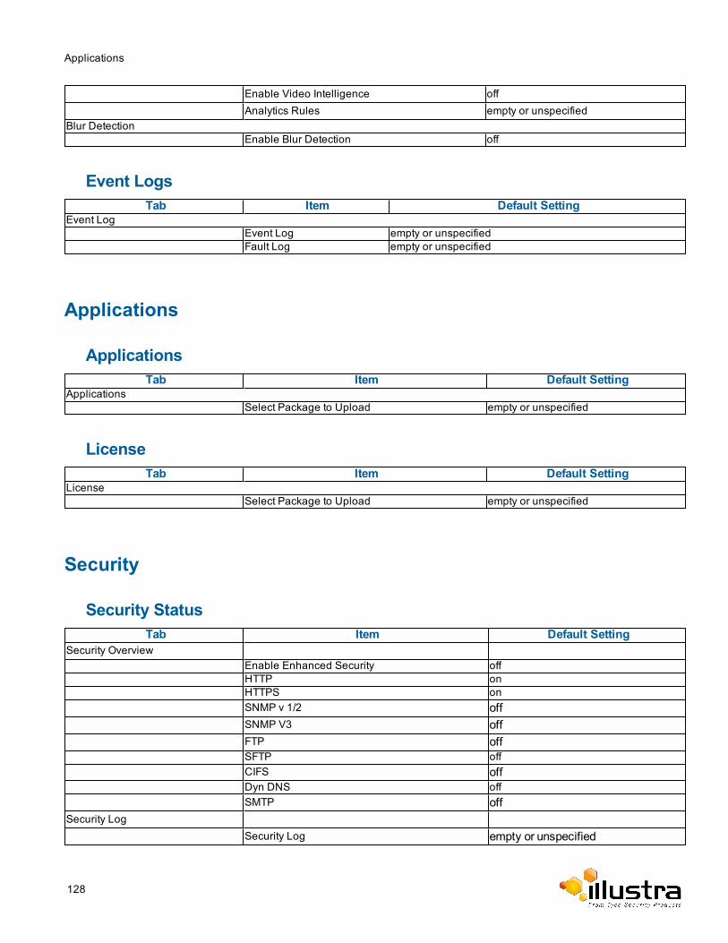
Applications
Enable Video Intelligence offAnalytics Rules empty or unspecified
Blur DetectionEnable Blur Detection off
Event LogsTab Item Default Setting
Event LogEvent Log empty or unspecifiedFault Log empty or unspecified
Applications
ApplicationsTab Item Default Setting
ApplicationsSelect Package to Upload empty or unspecified
LicenseTab Item Default Setting
LicenseSelect Package to Upload empty or unspecified
Security
Security StatusTab Item Default Setting
Security OverviewEnable Enhanced Security offHTTP onHTTPS onSNMP v 1/2 offSNMP V3 offFTP offSFTP offCIFS offDyn DNS offSMTP off
Security LogSecurity Log empty or unspecified
128
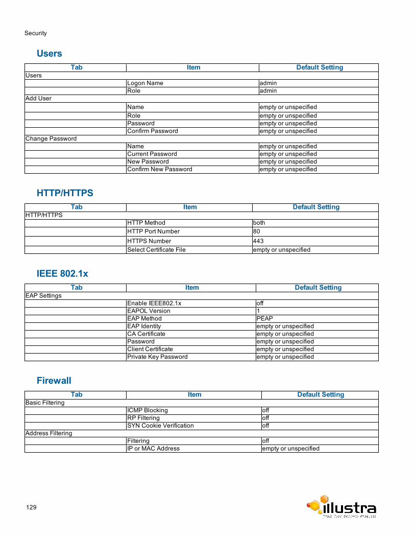
Security
UsersTab Item Default Setting
UsersLogon Name adminRole admin
Add UserName empty or unspecifiedRole empty or unspecifiedPassword empty or unspecifiedConfirm Password empty or unspecified
Change PasswordName empty or unspecifiedCurrent Password empty or unspecifiedNew Password empty or unspecifiedConfirm New Password empty or unspecified
HTTP/HTTPSTab Item Default Setting
HTTP/HTTPSHTTP Method bothHTTP Port Number 80HTTPS Number 443Select Certificate File empty or unspecified
IEEE 802.1xTab Item Default Setting
EAP SettingsEnable IEEE802.1x offEAPOL Version 1EAP Method PEAPEAP Identity empty or unspecifiedCA Certificate empty or unspecifiedPassword empty or unspecifiedClient Certificate empty or unspecifiedPrivate Key Password empty or unspecified
FirewallTab Item Default Setting
Basic FilteringICMP Blocking offRP Filtering offSYN Cookie Verification off
Address FilteringFiltering offIP or MAC Address empty or unspecified
129
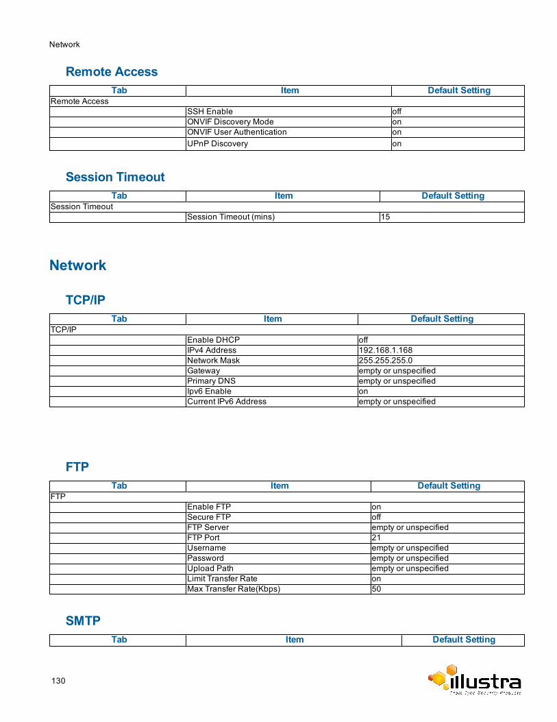
Network
Remote AccessTab Item Default Setting
Remote AccessSSH Enable offONVIF Discovery Mode onONVIF User Authentication onUPnP Discovery on
Session TimeoutTab Item Default Setting
Session TimeoutSession Timeout (mins) 15
Network
TCP/IPTab Item Default Setting
TCP/IPEnable DHCP offIPv4 Address 192.168.1.168Network Mask 255.255.255.0Gateway empty or unspecifiedPrimary DNS empty or unspecifiedIpv6 Enable onCurrent IPv6 Address empty or unspecified
FTPTab Item Default Setting
FTPEnable FTP onSecure FTP offFTP Server empty or unspecifiedFTP Port 21Username empty or unspecifiedPassword empty or unspecifiedUpload Path empty or unspecifiedLimit Transfer Rate onMax Transfer Rate(Kbps) 50
SMTPTab Item Default Setting
130
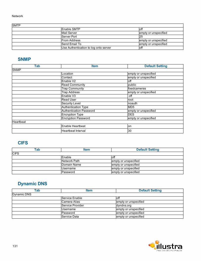
Network
SMTPEnable SMTP offMail Server empty or unspecifiedServer Port 25From Address empty or unspecifiedSend Email To empty or unspecifiedUse Authentication to log onto server off
SNMPTab Item Default Setting
SNMPLocation empty or unspecifiedContact empty or unspecifiedEnable V2 offRead Community publicTrap Community fixedcamerasTrap Address empty or unspecifiedEnable V3 offRead User rootSecurity Level noauthAuthentication Type MD5Authentication Password empty or unspecifiedEncryption Type DESEncryption Password empty or unspecified
HeartbeatEnable Heartbeat onHeartbeat Interval 30
CIFSTab Item Default Setting
CIFSEnable offNetwork Path empty or unspecifiedDomain Name empty or unspecifiedUsername empty or unspecifiedPassword empty or unspecified
Dynamic DNSTab Item Default Setting
Dynamic DNSService Enable offCamera Alias empty or unspecifiedService Provider dyndns.orgUsername empty or unspecifiedPassword empty or unspecifiedService Data empty or unspecified
131
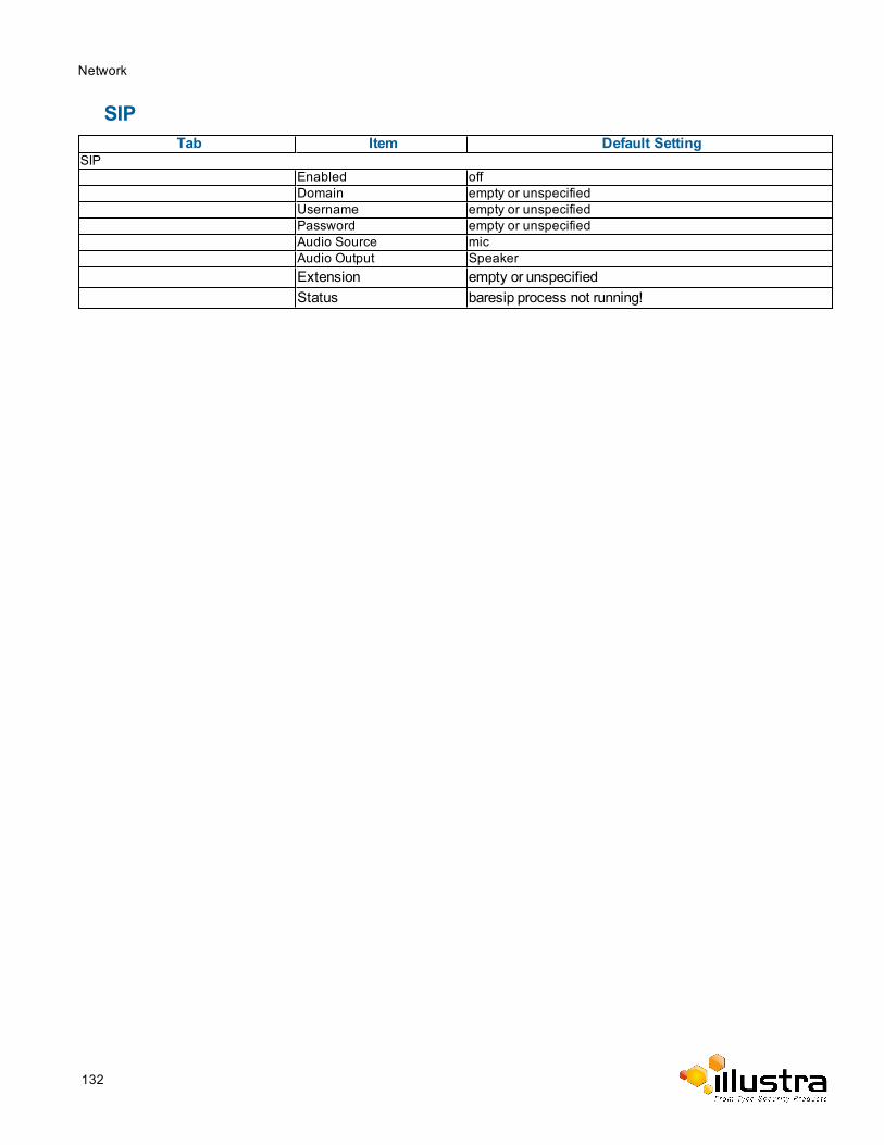
Network
SIPTab Item Default Setting
SIPEnabled offDomain empty or unspecifiedUsername empty or unspecifiedPassword empty or unspecifiedAudio Source micAudio Output SpeakerExtension empty or unspecifiedStatus baresip process not running!
132
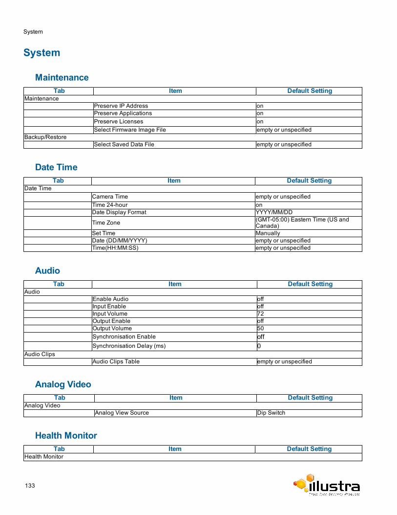
System
System
MaintenanceTab Item Default Setting
MaintenancePreserve IP Address onPreserve Applications onPreserve Licenses onSelect Firmware Image File empty or unspecified
Backup/RestoreSelect Saved Data File empty or unspecified
Date TimeTab Item Default Setting
Date TimeCamera Time empty or unspecifiedTime 24-hour onDate Display Format YYYY/MM/DD
Time Zone (GMT-05:00) Eastern Time (US andCanada)
Set Time ManuallyDate (DD/MM/YYYY) empty or unspecifiedTime(HH:MM:SS) empty or unspecified
AudioTab Item Default Setting
AudioEnable Audio offInput Enable offInput Volume 72Output Enable offOutput Volume 50Synchronisation Enable offSynchronisation Delay (ms) 0
Audio ClipsAudio Clips Table empty or unspecified
Analog VideoTab Item Default Setting
Analog VideoAnalog View Source Dip Switch
Health MonitorTab Item Default Setting
Health Monitor
133
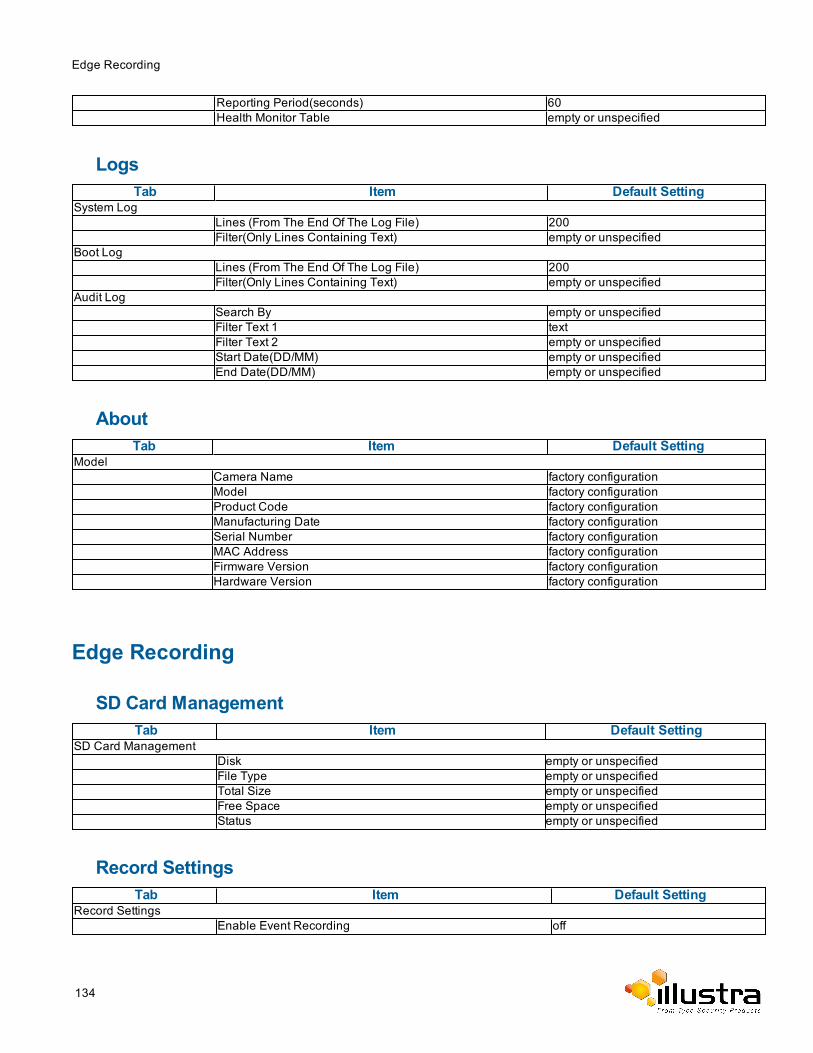
Edge Recording
Reporting Period(seconds) 60Health Monitor Table empty or unspecified
LogsTab Item Default Setting
System LogLines (From The End Of The Log File) 200Filter(Only Lines Containing Text) empty or unspecified
Boot LogLines (From The End Of The Log File) 200Filter(Only Lines Containing Text) empty or unspecified
Audit LogSearch By empty or unspecifiedFilter Text 1 textFilter Text 2 empty or unspecifiedStart Date(DD/MM) empty or unspecifiedEnd Date(DD/MM) empty or unspecified
AboutTab Item Default Setting
ModelCamera Name factory configurationModel factory configurationProduct Code factory configurationManufacturing Date factory configurationSerial Number factory configurationMAC Address factory configurationFirmware Version factory configurationHardware Version factory configuration
Edge Recording
SD Card ManagementTab Item Default Setting
SD Card ManagementDisk empty or unspecifiedFile Type empty or unspecifiedTotal Size empty or unspecifiedFree Space empty or unspecifiedStatus empty or unspecified
Record SettingsTab Item Default Setting
Record SettingsEnable Event Recording off
134
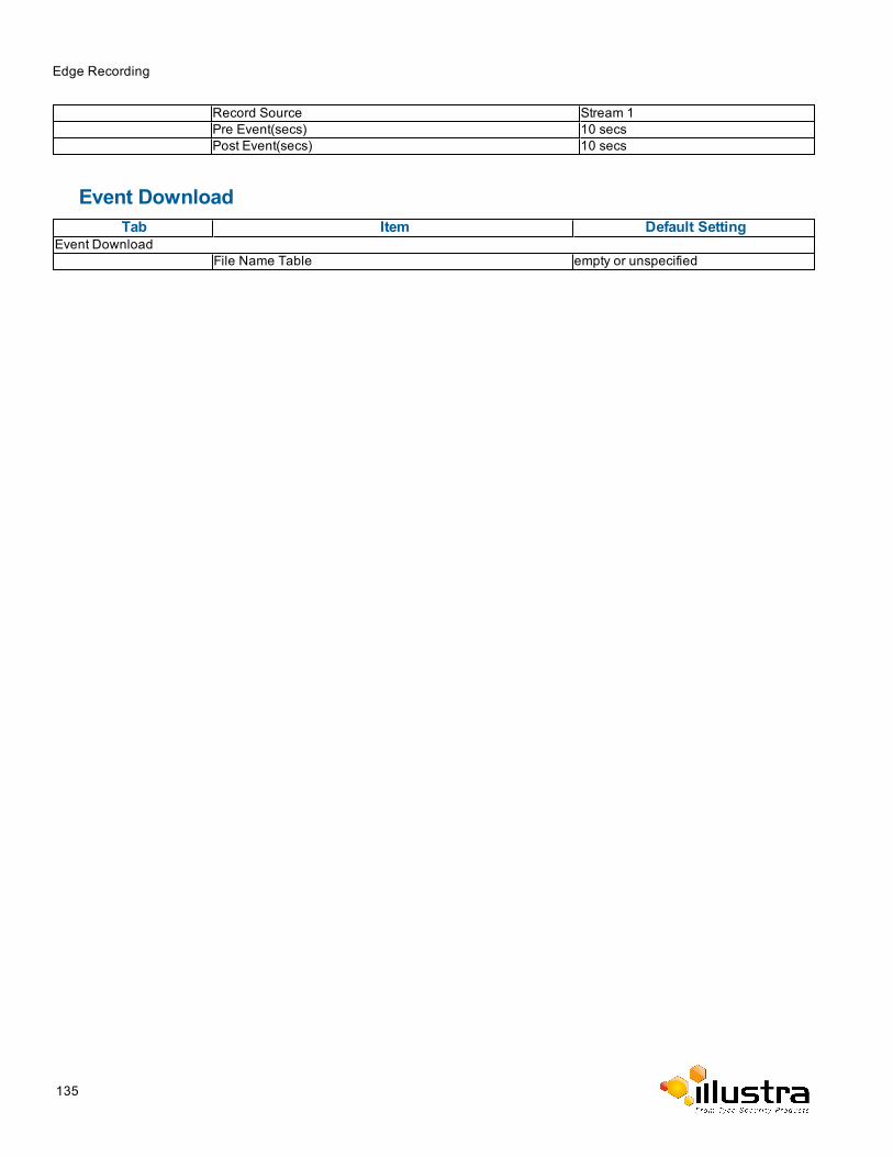
Edge Recording
Record Source Stream 1Pre Event(secs) 10 secsPost Event(secs) 10 secs
Event DownloadTab Item Default Setting
Event DownloadFile Name Table empty or unspecified
135