Embed Size (px)
Citation preview
Illumination system design for athree-aspherical-mirror projection camera forextreme-ultraviolet lithography
Yanqiu Li, Hiroo Kinoshita, Takeo Watanabe, Shigeo Irie, Shigeru Shirayone, andShinji Okazaki
A scanning critical illumination system is designed to couple a synchrotron radiation source to a three-aspherical-mirror imaging system for extreme ultraviolet lithography. A static illumination area of H 3V 5 8 mm 3 3 mm ~where H is horizontal and V is vertical! can be obtained. Uniform intensitydistribution and a large ring field of H 3 V 5 150 mm 3 3 mm can be achieved by scanning of the mirrorof the condenser. The coherence factor ~s! of this illumination system is ;0.6, with the same beamdivergence in both the horizontal and the vertical directions. We describe the performance of theimaging optics at s 5 0.6 to confirm that the illumination optics can meet the requirements for three-aspherical-mirror imaging optics with a feature size of 0.06 mm. © 2000 Optical Society of America
OCIS codes: 220.3740, 220.4830, 150.2950.
tmwtbt
car
1. Introduction
Recent significant progress in extreme ultraviolet li-thography ~EUVL! has demonstrated that EUVL is apromising technology for supporting the semiconduc-tor industry’s needs during the first decade of the 21stcentury.1–4 EUVL is expected to support many ap-plications for which components have critical dimen-sions below 100 to 30 nm. The important issues ofEUVL, i.e., source, illumination optics, imaging op-tics, reflective masks, sensitive resists, multilayercoatings, and metrology, have been developing in re-cent years. The design of an appropriate illumina-tion system, which is one of the key requirements forEUVL, couples a radiation source with an imagingsystem, providing uniform illumination within a spe-
When this research was performed, Y. Li, H. Kinoshita, and T.Watanabe were with the Laboratory of Advanced Science andTechnology for Industry, Himeji Institute of Technology, 3-1-2,Kamigori-machi, Kouto, Ako-gun Hyougo prefecture, 678-1205, Ja-pan. Y. Li’s present address is Shinsa-ku 5-11-6, Takatu-ku,Kawasak-Si, Kanagawa-ken, 213-0014, Japan. S. Irie, S. Shira-yone, and S. Okazaki are with the Atsugi Research Center ofAssociation of Super-Advanced Electronics Technology (ASET),3-1, Morino-Sato Wakamiya, Atsugi-shi, Kanagawa prefecture,243-0198, Japan.
Received 28 October 1999; revised manuscript received 29 Feb-ruary 2000.
0003-6935y00y193253-08$15.00y0© 2000 Optical Society of America
cific coherence factor and area at the mask and pro-vides the appropriate directions of illumination tomatch the imaging optics. Achievement of a syn-chrotron radiation ~SR! source and a large numericalaperture in a large ring field imaging system are newchallenges and difficulties for illumination system de-sign.5 There are several approaches to designing il-lumination optics for laser plasma sources andpractical imaging systems.6–10 A few publicationshave reported the design of illumination systems inwhich SR sources were used,5,11–13 and two SRsources were designed for practical imaging sys-tems.5,11 Reference 11 has presented the design con-cepts for four-mirror imaging optics without imageevaluation of the illumination. The illuminationsystem of Ref. 5 was designed for two-mirror imagingoptics with a static illumination area of H 3 V 5 3.5mm 3 1.5 mm, ~where H is horizontal and V is ver-ical! at the mask that could not meet the require-ents for a three-aspherical-mirror imaging systemith a large exposure field. An EUVL laboratory
ool is being constructed in our laboratory. A feasi-le illumination system for coupling a SR source to ahree-aspherical-mirror imaging optics is needed.
Here we present an illumination system design foroupling a SR source ~wavelength, 13 nm! to three-spherical-mirror imaging optics for EUVL. Theay tracing program SHADOW yields a reliable quanti-
tative estimate of the illumination area, intensitydistribution, and beam divergence. The coherence
1 July 2000 y Vol. 39, No. 19 y APPLIED OPTICS 3253
ihfl
tmtnaa
wla
Table 1. Specifications of the SR Source
3
factor of this illumination system is 0.6. The staticillumination area is H 3 V 5 8 mm 3 3 mm. Onecan obtain a uniform intensity distribution and alarge chord length ~150 mm! of the illumination byscanning the mirror of a condenser. We evaluatethe performance of the three-mirror imaging opticsby considering partially coherent ~s 5 0.6! illumina-tion. The results show that this illumination systemcan meet the requirements for a three-mirror imag-ing system with a feature size of 0.06 mm. The de-sign methods and results are discussed in Section 2.
2. Design of the Illumination System
As the illumination system is used to couple a radi-ation source to an imaging system, its design is con-strained by the parameters of the source and of theimaging optics. Different sources and imaging sys-tems have different parameters and therefore requireunique illumination systems for appropriate unifor-mity, coherence, illumination area, divergence, anddirection at the mask. Our illumination system isdesigned for the EUVL laboratory tool of a three-aspherical-mirror projection camera with a SR sourcethat already exists. We describe the design of theillumination system in the following subsections:2.A, the features of our SR source; 2.B, the specifica-tions and the illumination requirements of the three-aspherical-mirror imaging optics; 2.C, design issuesand results; and 2.D, the performance of the imagingoptics at s 5 0.6.
A. Features of the Synchrotron Radiation Source
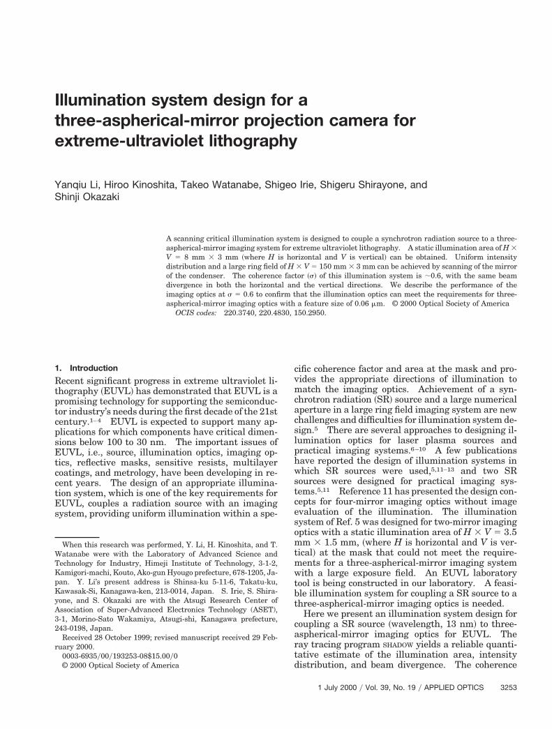
The specifications of the SR source in our laboratoryare listed in Table 1. For a SR divergence of an x-raybeam is determined by the divergence of the electronbeam ~related to its emittance! and the natural di-vergence of the created photons. As has been men-tioned in the literature,5 the small, anisotropicemittance of a SR source makes design of an illumi-nation system difficult. The source size and thebeam divergence are obtained by use of the SHADOW
program, as shown in Fig. 1. The source image inreal space has a source size of 1.5 mm in diameter atFWHM. The source divergences are 40 and 4 mradin the horizontal and vertical directions, respectively.It is well known that a good illumination systemshould illuminate the mask with the same divergencein both the vertical direction and the horizontal di-rections to match the numerical aperture ~NA! of theimaging optics. A feasible illumination system de-sign will be required to make the source illumination
Parameter Value
Beam energy 1.5 GeVBending radius 3.219 mBeam current ,500 mABending field 1.55 THorizontal emittance 3.35 3 1028 mm radVertical emittance 3.35 3 1029 mm rad
254 APPLIED OPTICS y Vol. 39, No. 19 y 1 July 2000
isotropic such that the spatial coherence will be thesame in the horizontal and the vertical directions.8
B. Illumination Requirements of the Three-Mirror ImagingOptics
The specifications of the three-aspherical-mirror im-aging optics are listed in Table 2. The details of thisthree-aspherical-mirror imaging optics have beenpresented in Ref. 4. The camera has a reductionratio of 5:1, a mask object shape specified as an arc of125-mm central radius, a chord length of 150 mm,and a ring width of 5 mm. The mask’s NA ~NAmask!s 0.02, where the NA is defined as the sine of thealf-angle subtended by the entrance pupil viewedrom a point on the mask. The entrance pupil isocated a distance of L 5 3487 mm from the mask and
has a 139.48-mm diameter ~DEP 5 2NAmask 3 L!.The incident angle of the principal ray onto the maskis 2.05°.
The imaging optics in our design requires that ~1!he illumination through every part of the object atask have a divergence of 40 mrad and fill the en-
rance pupil of 139.48-mm diameter; ~2! the illumi-ation area at the mask measure 150 mm 3 5 mm,nd ~3! the beam illuminate the mask at an incidentngle of 2.05°.The theory of paraxial rays optics can be employedhen we magnify an object with well-collimated
ight. From this theory, there is an optical invari-nt, I 5 S0F0 5 SiFi, where S0 and Si are the object
and the image sizes and F0 and Fi are the angulardivergences of the object and the image, respectively.
Fig. 1. ~a! Simulation image of the source in real space, ~b! sim-ulation beam divergence of the source in angle space.
Table 2. Specifications of Three-Aspherical-Image Optics
Parameters Value
Wavelength 13 nmNumerical aperture at wafer 0.1Magnification 1 y5Resolution 0.1 mmDepth of focus 1.9 mmResolution limit 0.06 mmExposure field size at wafer H 3 V 5 30 mm 3 1 mmDistance between entrance
pupil and mask, L3487 mm
6m
v
dmtFmmo4
fi
e
inr
For our three-aspherical-mirror camera we have ahorizontal invariant of Imask
h 5 150 mm 3 0.04 rad 5000 mm mrad and a vertical invariant of Imask
v 5 3m 3 0.04 rad 5 120 mm mrad at the mask. The
optical invariants of our SR source are Imaskh 5 1.5
mm 3 0.04 rad 5 60 mm mrad and Imaskv 5 1.5 mm 3
0.004 rad 5 6 mm mrad in the horizontal and theertical directions, respectively.An illumination beam that comes from a SR source
irectly cannot meet those imaging optics require-ents because the divergence in the vertical direc-
ion is only 4 mrad and the source size is only 1.5 mm.or the optical invariants mentioned above, the illu-ination area of the mask would be H 3 V 5 1.5m 3 0.15 mm if we used 103 vertical magnifying
ptics to directly extend the source divergence to be0 mrad in the vertical direction.5 Therefore special
design issues arise.
C. Design Issues and Results of Illumination System
One of the illumination requirements for the three-aspherical-mirror imaging optics is that the illumi-nation fill an entrance pupil of 139.48-mm diameter.However, the sharpest high-contrast images with asmall feature size are obtained when the entrancepupil is not completely filled.11 The fraction of thediameter of the filled pupil is commonly used to definethe coherence factor ~s! of the illumination system;i.e., s 5 DFEPyDEP, where DFEP is the diameter of the
lled entrance pupil and DEP is the diameter of theentrance pupil. For projection lithography the opti-mized partial coherence of the illumination is com-monly said to be in the range 0.5 , s , 0.7.7 Thusone task of the illumination system is to direct thesource radiation through every part of the object atthe mask in a direction that passes through the pupiland fills it in the required area. Every point on themask should be illuminated with light of divergenceFmask 5 2sNAmask. In the other words, the coher-nce factor can be expressed as s 5 Fmasky2NAmask.
The diameter of the filled entrance pupil DFEP andthe light divergence at the mask Fmask can be ob-tained with the ray-tracing program SHADOW, so wecan evaluate the degree of coherence of our illumina-tion system. The best illumination systems for four-and two-mirror imaging optics, in which the sourcesare different from our SR source, can fill 70% of theentrance pupil ~s 5 0.7!.2,5
Another task of our illumination system is to illu-minate an arc-shaped mask in a large area, H 3 V 5150 mm 3 5 mm, with uniform intensity and anincident angle of 2.05° onto the mask. The geomet-rical constraints of the optical design are the heightfrom the optical axis of the mask and the size of theillumination area. The geometrical constraint canbe eliminated by the choice of grazing angle and ofposition and radius of the mirror. The mirror posi-tion also has to match the requirement for magnifi-cation, which is determined by the source parametersand the imaging optics. In addition, the design pa-rameters are affected by the kind of illumination usedin the design.
There are two types of illumination system. AKohler illumination system images the source ontothe entrance pupil of imaging system and the aper-ture stop of the illumination system onto the maskplane. A critical illumination system images thesource onto the mask and relays the aperture stop ofthe illumination system to the entrance pupil of theimaging system. Comparisons of the critical and theKohler illumination systems have been made.5,9,10
The Kohler system generally provides better illumi-nation uniformity, but it is difficult to maintain a bigsymmetric divergence of Fmask 5 2sNAmask in a largellumination field. The advantage of critical illumi-ation is that a larger divergence on the mask can beeached, so a large coherence factor s can be realized.
One can achieve a uniform intensity distribution byscanning the mirror of the condenser.
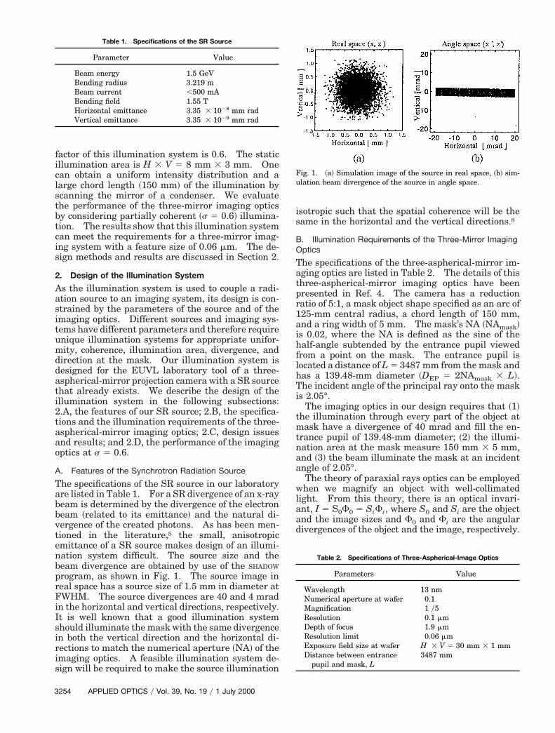
We employ the critical type of illumination in ourdesign. A schematic diagram of this illuminationsystem is shown in Fig. 2. Taking into account thefeatures of the SR source, the illumination require-ments of the imaging optics, and the concepts asso-ciated with illumination design, we designed anillumination system with two sets of optics, i.e., col-limated concave toroidal mirrors ~M1 and M2! anddemagnification optics with scanning cylindrical mir-ror C1 and concave toroidal mirror C2.
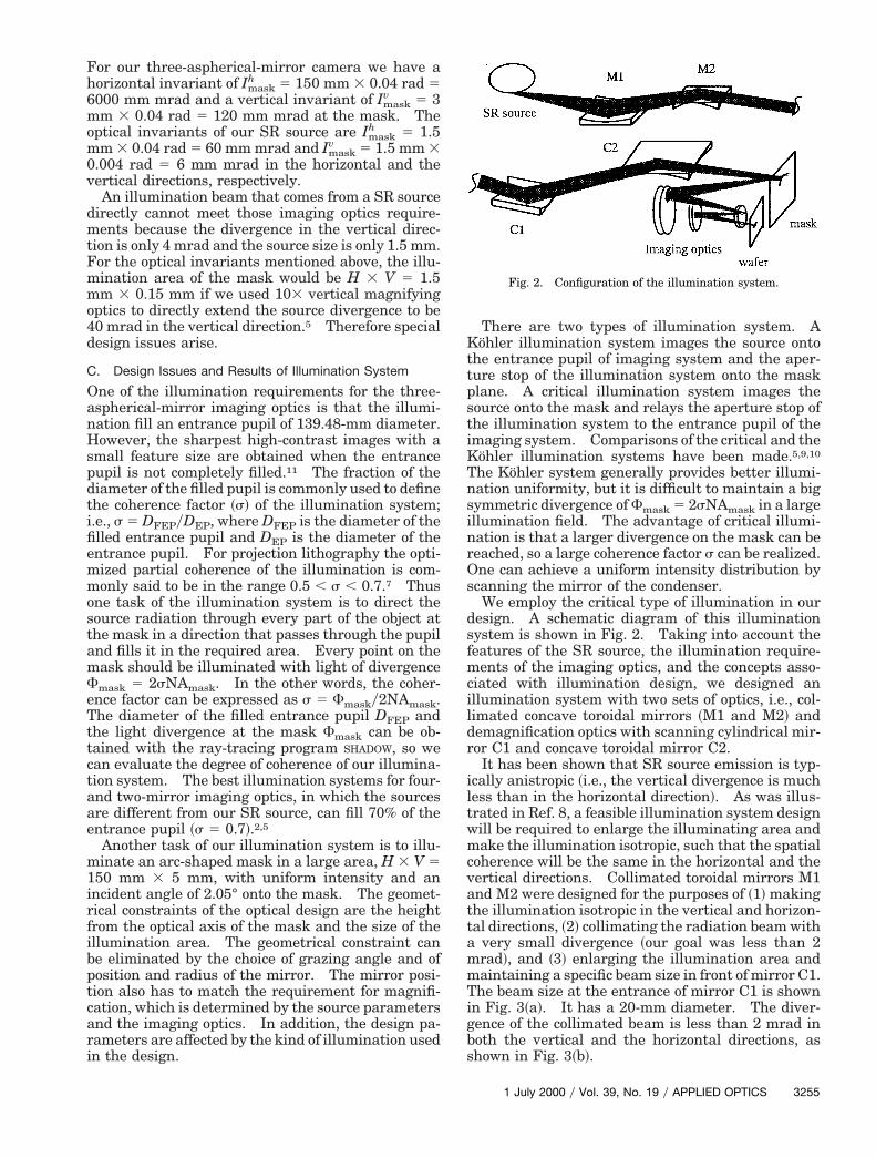
It has been shown that SR source emission is typ-ically anistropic ~i.e., the vertical divergence is muchless than in the horizontal direction!. As was illus-trated in Ref. 8, a feasible illumination system designwill be required to enlarge the illuminating area andmake the illumination isotropic, such that the spatialcoherence will be the same in the horizontal and thevertical directions. Collimated toroidal mirrors M1and M2 were designed for the purposes of ~1! makingthe illumination isotropic in the vertical and horizon-tal directions, ~2! collimating the radiation beam witha very small divergence ~our goal was less than 2mrad!, and ~3! enlarging the illumination area andmaintaining a specific beam size in front of mirror C1.The beam size at the entrance of mirror C1 is shownin Fig. 3~a!. It has a 20-mm diameter. The diver-gence of the collimated beam is less than 2 mrad inboth the vertical and the horizontal directions, asshown in Fig. 3~b!.
Fig. 2. Configuration of the illumination system.
1 July 2000 y Vol. 39, No. 19 y APPLIED OPTICS 3255
T
sf
r
ktta
3
We use cylindrical mirror C1, defined as a stop ofthe condenser, to demagnify the beam in the horizon-tal direction. We obtain the large arc-shaped ringfield by scanning mirror C1 about the optical axis ofthe imaging system. Toroidal mirror C2 is used todemagnify the beam in the horizontal and the verti-cal directions.
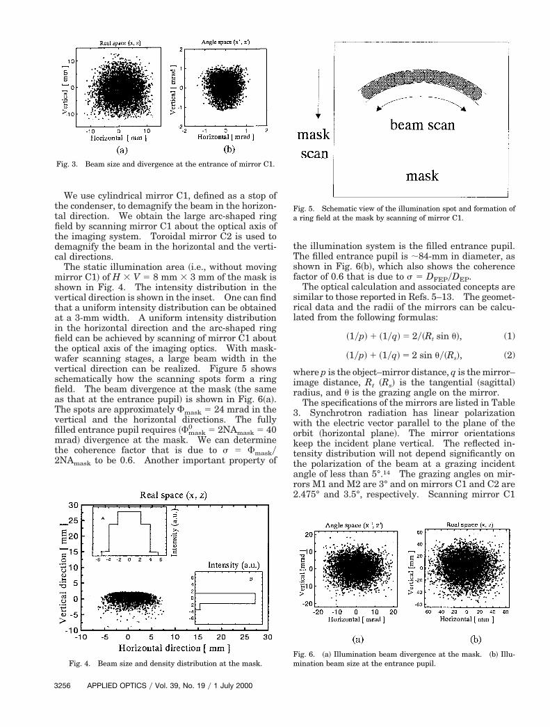
The static illumination area ~i.e., without movingmirror C1! of H 3 V 5 8 mm 3 3 mm of the mask isshown in Fig. 4. The intensity distribution in thevertical direction is shown in the inset. One can findthat a uniform intensity distribution can be obtainedat a 3-mm width. A uniform intensity distributionin the horizontal direction and the arc-shaped ringfield can be achieved by scanning of mirror C1 aboutthe optical axis of the imaging optics. With mask-wafer scanning stages, a large beam width in thevertical direction can be realized. Figure 5 showsschematically how the scanning spots form a ringfield. The beam divergence at the mask ~the sameas that at the entrance pupil! is shown in Fig. 6~a!.
he spots are approximately Fmask 5 24 mrad in thevertical and the horizontal directions. The fullyfilled entrance pupil requires ~Fmask
0 5 2NAmask 5 40mrad! divergence at the mask. We can determinethe coherence factor that is due to s 5 Fmasky2NAmask to be 0.6. Another important property of
Fig. 3. Beam size and divergence at the entrance of mirror C1.
Fig. 4. Beam size and density distribution at the mask.
256 APPLIED OPTICS y Vol. 39, No. 19 y 1 July 2000
the illumination system is the filled entrance pupil.The filled entrance pupil is ;84-mm in diameter, ashown in Fig. 6~b!, which also shows the coherenceactor of 0.6 that is due to s 5 DFEPyDEP.
The optical calculation and associated concepts aresimilar to those reported in Refs. 5–13. The geomet-rical data and the radii of the mirrors can be calcu-lated from the following formulas:
~1yp! 1 ~1yq! 5 2y~Rt sin u!, (1)
~1yp! 1 ~1yq! 5 2 sin uy~Rs!, (2)
where p is the object–mirror distance, q is the mirror–image distance, Rt ~Rs! is the tangential ~sagittal!adius, and u is the grazing angle on the mirror.
The specifications of the mirrors are listed in Table3. Synchrotron radiation has linear polarizationwith the electric vector parallel to the plane of theorbit ~horizontal plane!. The mirror orientations
eep the incident plane vertical. The reflected in-ensity distribution will not depend significantly onhe polarization of the beam at a grazing incidentngle of less than 5°.14 The grazing angles on mir-
rors M1 and M2 are 3° and on mirrors C1 and C2 are2.475° and 3.5°, respectively. Scanning mirror C1
Fig. 5. Schematic view of the illumination spot and formation ofa ring field at the mask by scanning of mirror C1.
Fig. 6. ~a! Illumination beam divergence at the mask. ~b! Illu-mination beam size at the entrance pupil.
aib
a
tl
r
Tu
ahi
0tn
Table 3. Specifications of Illumination Optics
may cause the polarization to depend on the intensitydistribution because a large ring field with a smallcentral radius is illuminated on the mask. A largespace ~'4300 mm! between C1 and C2 can result in
small scanning angle, which will reduce the polar-zation effect. The final optimized parameters cane obtained by a SHADOW simulation that can take into
account the effect of polarization. The uniformity is65% at the illumination area.
So far we have described the design and the ray-tracing results of our illumination system. TheM1–M2 optics is used to enlarge the illuminatingarea and to make the illumination isotropic such thatthe spatial coherence will be the same in the horizon-tal and the vertical directions. The C1–C2 optics isdesigned to extend the beam divergence and illumi-nate the mask in a large ring field. In Subsection2.D we evaluate the images in the imaging optics byconsidering partially coherent illumination to con-firm that the illumination system’s design meets therequirements of 0.06-mm resolution of the three-spherical-mirror imaging optics.
D. Performance of Imaging Optics under PartiallyCoherent Illumination
It has been reported that the image quality dependson the properties not only of the imaging system butalso of the illumination system.8,9,11 The degree of
Mirror Radius Rt ~mm! Radius Rs ~mm!
M1 51589.77 141.30M2 28660.98 78.50C1 81.89C2 75232.26 171.51
partial coherence will affect the image quality. Inlithography, the sharpest high-contrast images ofsmall features are obtained when the radiation illu-mination on the mask does not completely fill theentrance pupil.11 For projection lithography the op-timum level of partial coherence of the illumination iscommonly said to be in the range 0.5 , s , 0.7.7Wood et al.15 reported the performance of an aerialimage with a 0.1-mm feature size under the conditionof a half-filled entrance pupil ~s 5 0.5!. The resultsshow that the diffraction intensity profile ~image con-rast! with partially coherent illumination s 5 0.5 isarger than that with s 5 1. Wood et al. thus con-
cluded that, with partially coherent illumination, thedepth of focus may be even larger because the con-trast will be higher.
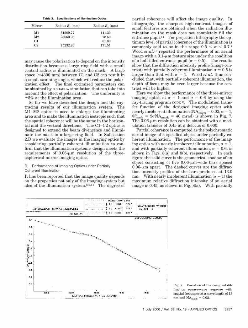
Here we show the performance of the three-mirrorimaging optics at s 5 1 and s 5 0.6 by using theay-tracing program CODE V. The modulation trans-
fer function of the designed imaging optics withnearly incoherent illumination ~NAmask 5 0.02, s 5 1,Fmask
0 5 2sNAmask 5 40 mrad! is shown in Fig. 7.he 0.06-mm resolution can be obtained with a mod-lation transfer of 0.45 at a defocus of 0.000.Partial coherence is computed as the polychromatic
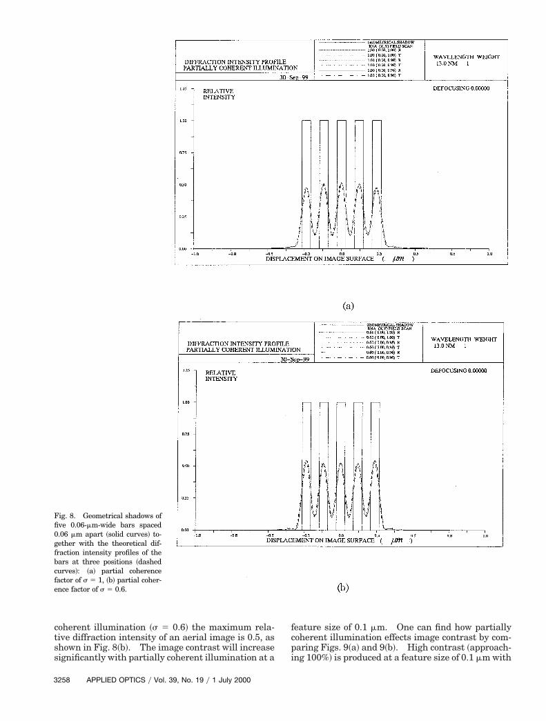
erial image of a specified object under partially co-erent illumination. The performance of the imag-
ng optics with nearly incoherent illumination, s 5 1,and with partially coherent illumination, s 5 0.6, isshown in Figs. 8~a! and 8~b!, respectively. In eachfigure the solid curve is the geometrical shadow of anobject consisting of five 0.06-mm-wide bars spaced.06-mm apart. The dashed curves are the diffrac-ion intensity profiles of the bars produced at 13.0m. With nearly incoherent illumination ~s 5 1! the
maximum relative diffraction intensity of an aerialimage is 0.45, as shown in Fig. 8~a!. With partially
Fig. 7. Variation of the designed dif-fraction square-wave response withspatial frequency at a wavelength of 13nm and NAmask 5 0.02.
1 July 2000 y Vol. 39, No. 19 y APPLIED OPTICS 3257
fi
3
coherent illumination ~s 5 0.6! the maximum rela-tive diffraction intensity of an aerial image is 0.5, asshown in Fig. 8~b!. The image contrast will increasesignificantly with partially coherent illumination at a
Fig. 8. Geometrical shadows ofve 0.06-mm-wide bars spaced
0.06 mm apart ~solid curves! to-gether with the theoretical dif-fraction intensity profiles of thebars at three positions ~dashedcurves!: ~a! partial coherencefactor of s 5 1, ~b! partial coher-ence factor of s 5 0.6.
258 APPLIED OPTICS y Vol. 39, No. 19 y 1 July 2000
feature size of 0.1 mm. One can find how partiallycoherent illumination effects image contrast by com-paring Figs. 9~a! and 9~b!. High contrast ~approach-ing 100%! is produced at a feature size of 0.1 mm with
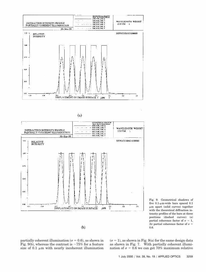
partially coherent illumination ~s 5 0.6!, as shown inFig. 9~b!, whereas the contrast is ;75% for a featuresize of 0.1 mm with nearly incoherent illumination
~s 5 1!, as shown in Fig. 9~a! for the same design dataas shown in Fig. 7. With partially coherent illumi-nation of s 5 0.6 we can get 70% maximum relative
Fig. 9. Geometrical shadows offive 0.1-mm-wide bars spaced 0.1mm apart ~solid curves! togetherwith the theoretical diffraction in-tensity profiles of the bars at threepositions ~dashed curves!: ~a!partial coherence factor of s 5 1,~b! partial coherence factor of s 50.6.
1 July 2000 y Vol. 39, No. 19 y APPLIED OPTICS 3259
tossat
3. J. E. M. Goldsmith, P. K. Barr, K. W. Berger, L. J. Bernardez
3
diffraction intensity of an image with a feature size of0.07 mm ~not shown here!. The diffraction profiles inFigs. 8~a! and 8~b! overlap well at three object posi-ions and are not shifted out of the geometrical shad-w; i.e., the 0.06-mm features are easily resolved at5 0.6. These results confirm that our illumination
ystem can achieve the requirements of three-spherical-mirror imaging optics of 0.06-mm resolu-ion.
3. Conclusions
We have designed an illumination system to couple asynchrotron radiation source and a three-aspherical-mirror imaging system for use as an extreme-ultraviolet lithographic laboratory tool. Ray-tracingwith the SHADOW program yields a reliable quantita-tive estimate of the illumination area, the intensitydistribution, and the beam divergence. We obtaineda uniform intensity distribution and a large ring fieldof dimensions H 3 V 5 150 mm 3 3 mm by scanningthe mirror of the condenser. But vertical illumina-tion on the mask could not reach the 5-mm levelrequired by imaging optics. The SHADOW ray-tracingresult yielded a coherence factor of 0.6 for this illu-mination system. Simulation performance of theimaging optics with the CODE V program for partiallycoherent illumination ~s 5 0.6! shows that a featuresize of 0.06 mm can easily be resolved. The designcharacteristics satisfy the basic requirements of im-aging optics.
We thank Franco Cerrira of the University of Wis-consin for supplying the SHADOW program. We aregrateful to Tsuneyuki Haga of NTT LSI Laboratoryof Japan for many discussions. The M1–M2 opticswas designed by Hiroo Kinoshita; the design wassupervised by Hiroo Kinoshita. This research issupported by the New Energy Development Organi-zation of Japan.
References1. H. Kinoshita, K. Kurihara, T. Mizota, T. Haga, H. Takenaka,
and Y. Torii, “Large-area, height-resolution pattern replicationby the use of a two-aspherical-mirror system,” Appl. Opt. 34,7079–7083 ~1993!.
2. D. W. Sweeney, R. M. Hudyma, and H. N. Chapman, “EUVoptical design for a 100-nm CD imaging system,” in EmergingLithographic Technologies II, Y. Vladimirsky, ed., Proc. SPIE3331, 2–10 ~1998!.
260 APPLIED OPTICS y Vol. 39, No. 19 y 1 July 2000
II, G. F. Cardinsle, J. R. Darnold, D. R. Folk, S. J. Haney, C. C.Henderson, K. L. Jefferson, K. D. Krenz, G. D. Kubiak, R. P.Nissen, D. J. O’Connell, Y. E. Perras, A. K. Ray-Chaudhuri,T. G. Smith, R. H. Stulen, D. A. Tichenor, A. A. Ver Berkmoes,and J. B. Wronosky, “Recent advances in the Sendia EUV 103microstepper,” in Emerging Lithographic Technologies II, Y.Vladimirsky, ed., Proc. SPIE 3331, 11–19 ~1998!.
4. H. Kinoshita, T. Watanabe, M. Niibe, H. Oizumi, H. Yama-nashi, K. Murakami, T. Oshino, Y. Y. Platonv, and N. Grupido,“Three-aspherical-mirror system for EUV lithography,” inEmerging Lithographic Technologies II, Y. Vladimirsky, ed.,Proc. SPIE 3331, 20–31 ~1998!.
5. T. Haga and H. Kinoshita, “Illumination system for extremeultraviolet lithography,” J. Vac. Sci. Technol. B 13, 2914–2918~1995!.
6. D. A. Tichenor, A. K. Ray-Chaudhuri, G. D. Kubiak, K. B.Nguyen, S. J. Haney, K. W. Berger, R. P. Nissen, Y. E. Perras,P. S. Jin, L. I. Weingarten, P. N. Keifer, and R. H. Stulen,“Progress in the development of EUV image systems,” in Ex-treme Ultraviolet Lithography, G. D. Kubiak and D. R. Kania,eds., Vol. 4 of OSA Trends in Optics and Photonics Series~Optical Society of America, Washington, D.C., 1996!, pp. 2–8.
7. W. C. Sweatt and G. N. Lawrence, “Physical optics modeling insoft-x-ray projection lithography,” Appl. Opt. 32, 6945–6951~1993!.
8. N. M. Ceglio, A. M. Hawryluk, and G. E. Sommargren, “Front-end design issues in soft-x-ray projection lithography,” Appl.Opt. 32, 7050–7056 ~1993!.
9. G. E. Sommargren and L. G. Seppala, “Condenser optics, par-tial coherence, and imaging for soft-x-ray projection lithogra-phy,” Appl. Opt. 32, 6938–6944 ~1993!.
10. S. J. Cohen and L. G. Seppala, “Critical illumination condenserfor EUV projection lithography,” in Extreme Ultraviolet Li-thography, D. Attwood and F. Zernike, eds., Vol. 23 of OSAProceedings Series ~Optical Society of America, Washington,D.C., 1994!, pp. 109–115.
11. J. B. Murphy, D. L. White, A. A. MacDwell, and O. R. Wood II,“Synchrotron radiation source and condenser for projectionx-ray lithography,” Appl. Opt. 32, 6920–6929 ~1993!.
12. S. Goto, T. Taguchi, T. Osada, S. Okamura, and T. Hisatsugu,“Synchrontron radiation beamline for x-ray lithography,” J.Vac. Sci. Technol. B. 11, 286–295 ~1993!.
13. E. Di Fabrizio, A. Nucara, M. Gentili, and R. Cingolani, “De-sign of a beamline for soft and deep lithography on third gen-eration synchrotron radiation source,” Rev. Sci. Instrum. 70,1605–1613 ~1999!.
14. H. E. White, Fundamentals of Optics, 4th ed. ~McGraw-Hill,New York, 1981!, p. 530.
15. O. R. Wood II, W. T. Silfvast, and T. E. Jewell, “Short-wavelength annular-field optical system for imaging tenth-micron features,” J. Vac. Sci. Technol. B 7, 1613–1615 ~1989!.