Embed Size (px)
Citation preview

Illinois
Drafting Educators
Association
Curriculum Committee
Basic Drafting Guidelines Fall 2005

2
I.D.E.A. Curriculum Committee Project Staff Chairs: Mike Morgan Industrial Technology/Manufacturing Education Coordinator Lewis and Clark Community College 5800 N. Godfrey Road Godfrey, IL 62035 Email: [email protected]
Dr. Shauna Scribner, CMfgT, CD Computer-Aided Drafting Coordinator Associate Professor of Engineering Graphics Southwestern Illinois College 2500 Carlyle Ave Belleville, IL 62221 Email: [email protected] Members: Tim Bacak Crystal Lake Central High School 45 W. Franklin St. Crystal Lake, IL 60014 (815) 459-2505 Email: [email protected]
Norris Hurlbut Forrestville Valley Dist. 221 P.O. Box 665 Forreston, IL 61030 (815) 938-2036 Email: [email protected]
Theresa Luce Adjunct at Southwestern Illinois College Email: [email protected]
Maria Rafac Joliet Junior College 1216 Houbolt Ave. Joliet, IL 60436 (815) 743-9020 Email: [email protected]
Steve Schuerman Lewis and Clark College 5800 N. Godfrey Rd. Godfrey, IL 62035 (618) 469-4921 Email: [email protected]
Who should utilize this manual? Any and all professionals teaching either manual or computer-aided drafting concepts at the introductory level. This manual is to be used as a guide to help identify skills needed for students taking drafting/computer-aided drafting courses at the basic or introductory level.
3
Table of Contents
Performance Level ............................................................................... 4
Enabling Objective:......................................................................................................... 4
Terminal Objectives: ....................................................................................................... 4
Spatial Visualization........................................................................... 5
Coded Plans based on Isometric View: ...................................................................... 5
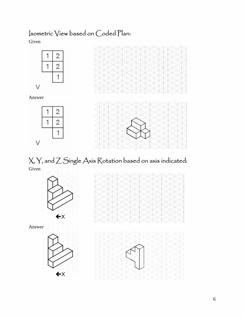
Isometric View based on Coded Plan: ........................................................................ 6
X, Y, and Z Single Axis Rotation based on axis indicated: ............................... 6
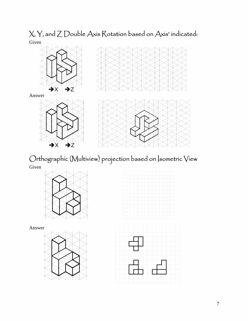
X, Y, and Z Double Axis Rotation based on Axis’ indicated: .......................... 7
Orthographic (Multiview) projection based on Isometric View........................... 7
Alphabet of Lines ............................................................................... 9
Lettering ...............................................................................................12
Freehand Sketching.........................................................................13
Computer-Aided Drafting ............................................................14
Orthographic and Multiview Projection .....................................16
Oblique and Axonometric Projection.........................................18
Dimensioning .......................................................................................19
Auxiliary Views ...................................................................................20
Sectional Views .................................................................................22
Glossary of Terms............................................................................25
Definition..............................................................................................25
Appendix ..............................................................................................33
4
Performance Level Enabling Objective:
Given the Basic Drafting Guidelines handout, mechanical pencils (0.9mm, 0.7mm, 0.5mm, 0.3mm), eraser, square grid and isometric grid paper, latest Computer-Aided Drafting software, floppy/zip disk/thumb drive, the student will be able to apply the basic drafting concepts related to both mechanical and architectural drafting as a sketch or a detailed drawing with a grade of a 75% or better.
Terminal Objectives:
Upon completion of the computer-aided drafting course the student will be able to:
demonstrate the ability to spatially visualize 3-Dimensional objects and sketch the
appropriate views to pictorially communicate the object drawn.
identify and apply the “Alphabet of Lines” according to ASME Y14.2M (1992)
Standards.
construct lettering according to ASME Y14.2M (1992) Standards.
sketch objects in orthographic, multiview (Y14.3-2003), axonometric (14.4M-
1998), and oblique projections (14.4M-1989) according to ASME Y14.100 (2000)
Standards.
create detailed drawings utilizing computer-aided-drafting software based on
sketches generated.
create sketches and detailed drawings utilizing inch (Y14.1-1995)and metric
(Y14.1M-1995) measurement.
dimension both sketches and CAD drawings according to ASME Y14.5M (1994)
and Y14.4M-1998 Standards.
construct section views according to ASME Y14.3 (2003) Standards.
construct auxiliary views according to ASME Y14.24 (1999) Standards.
revise drawings based on markups according to ASME Y14.34M (1997)
Standards.
5
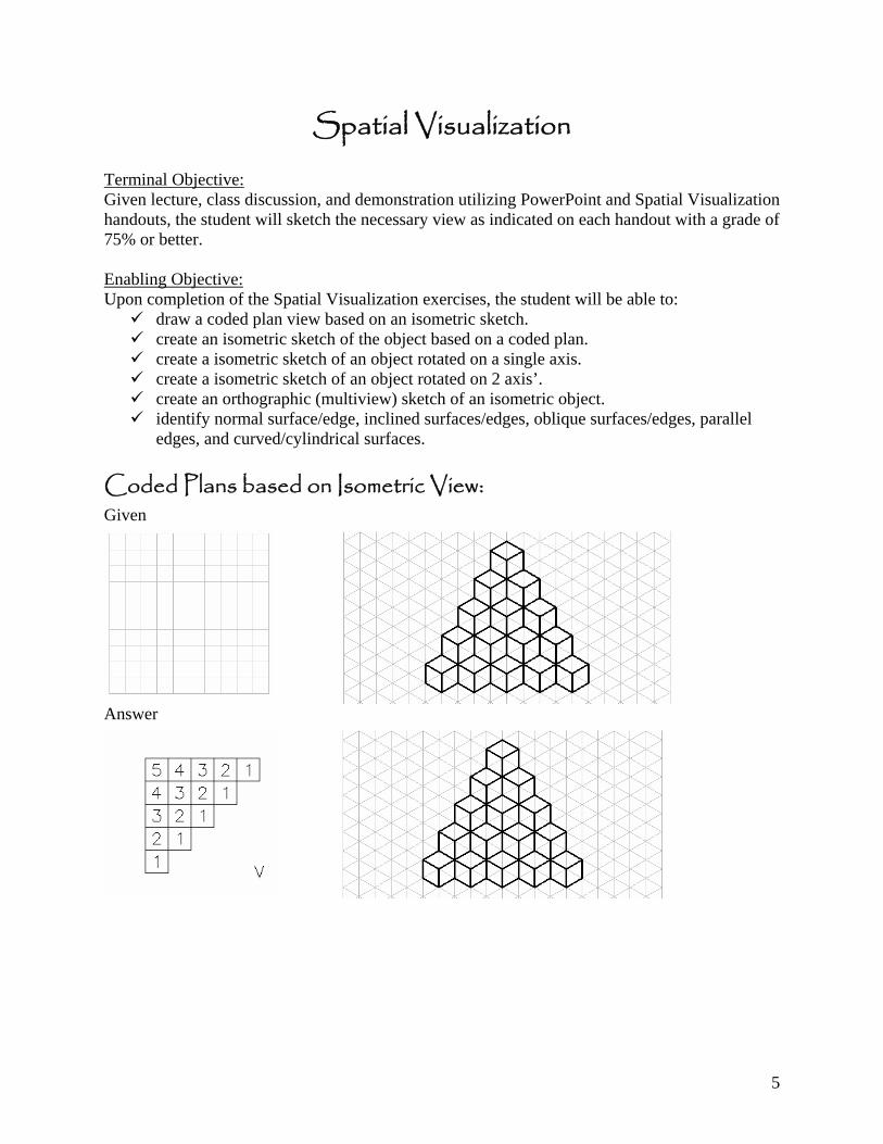
Spatial Visualization Terminal Objective: Given lecture, class discussion, and demonstration utilizing PowerPoint and Spatial Visualization handouts, the student will sketch the necessary view as indicated on each handout with a grade of 75% or better. Enabling Objective: Upon completion of the Spatial Visualization exercises, the student will be able to:
draw a coded plan view based on an isometric sketch. create an isometric sketch of the object based on a coded plan. create a isometric sketch of an object rotated on a single axis. create a isometric sketch of an object rotated on 2 axis’. create an orthographic (multiview) sketch of an isometric object. identify normal surface/edge, inclined surfaces/edges, oblique surfaces/edges, parallel
edges, and curved/cylindrical surfaces. Coded Plans based on Isometric View: Given
Answer
6
Isometric View based on Coded Plan: Given
Answer
X, Y, and Z Single Axis Rotation based on axis indicated: Given
X
Answer
X
7
X, Y, and Z Double Axis Rotation based on Axis’ indicated: Given
X Z
Answer
X Z
Orthographic (Multiview) projection based on Isometric View Given
Answer
8
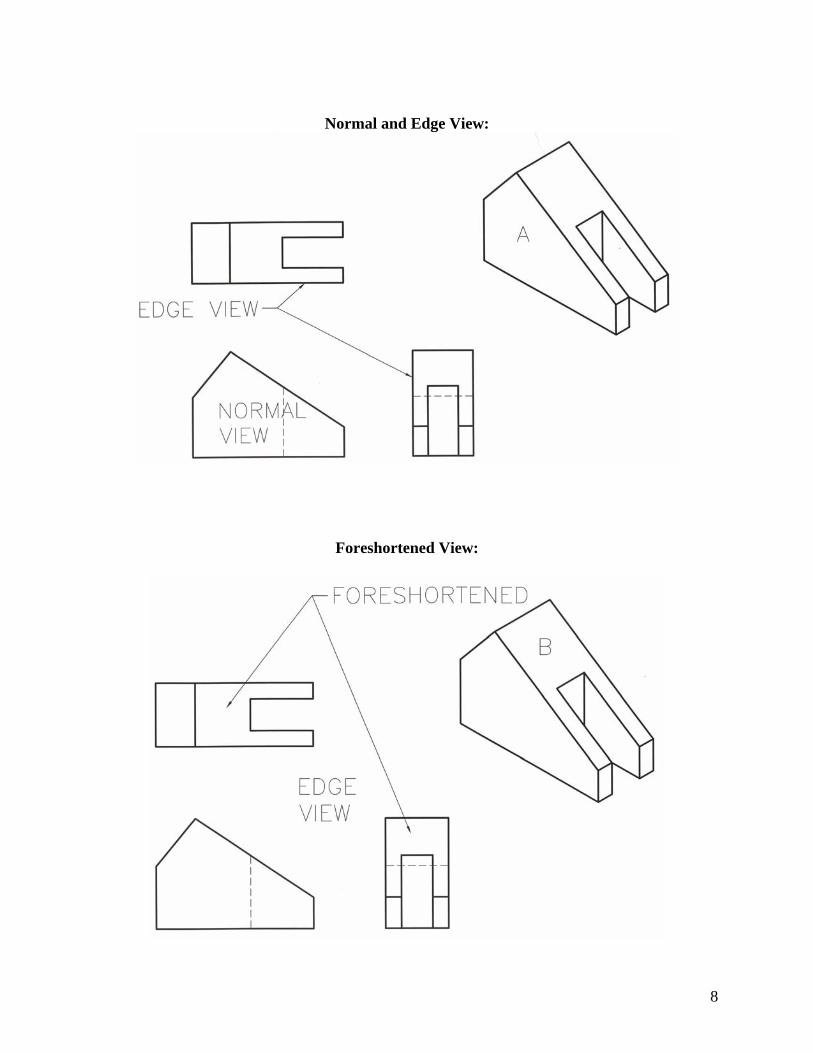
Normal and Edge View:
Foreshortened View:
9
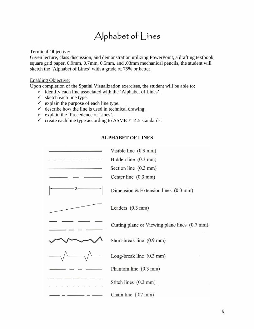
Alphabet of Lines Terminal Objective: Given lecture, class discussion, and demonstration utilizing PowerPoint, a drafting textbook, square grid paper, 0.9mm, 0.7mm, 0.5mm, and .03mm mechanical pencils, the student will sketch the ‘Alphabet of Lines’ with a grade of 75% or better. Enabling Objective: Upon completion of the Spatial Visualization exercises, the student will be able to:
identify each line associated with the ‘Alphabet of Lines’. sketch each line type. explain the purpose of each line type. describe how the line is used in technical drawing. explain the ‘Precedence of Lines’. create each line type according to ASME Y14.5 standards.
ALPHABET OF LINES
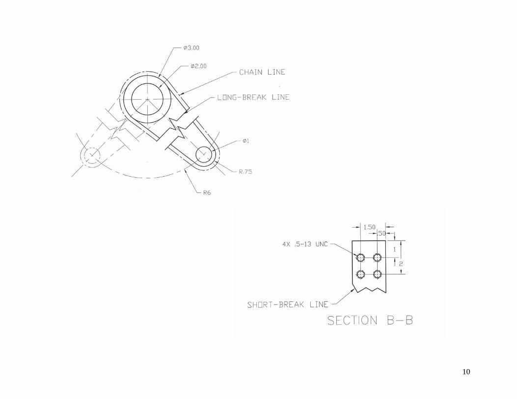
10
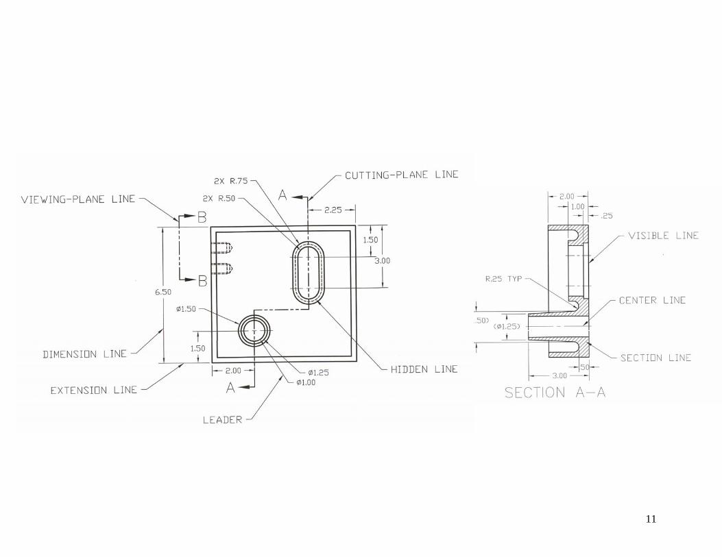
11
12
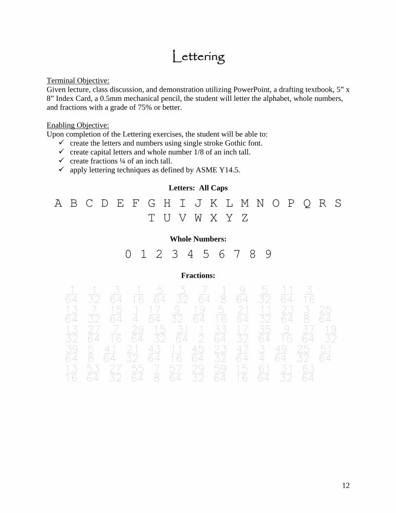
Lettering Terminal Objective: Given lecture, class discussion, and demonstration utilizing PowerPoint, a drafting textbook, 5” x 8” Index Card, a 0.5mm mechanical pencil, the student will letter the alphabet, whole numbers, and fractions with a grade of 75% or better. Enabling Objective: Upon completion of the Lettering exercises, the student will be able to:
create the letters and numbers using single stroke Gothic font. create capital letters and whole number 1/8 of an inch tall. create fractions ¼ of an inch tall. apply lettering techniques as defined by ASME Y14.5.
Letters: All Caps
A B C D E F G H I J K L M N O P Q R S T U V W X Y Z
Whole Numbers:
0 1 2 3 4 5 6 7 8 9
Fractions:
13
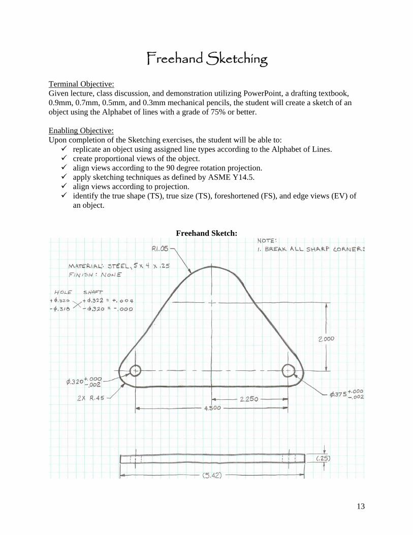
Freehand Sketching Terminal Objective: Given lecture, class discussion, and demonstration utilizing PowerPoint, a drafting textbook, 0.9mm, 0.7mm, 0.5mm, and 0.3mm mechanical pencils, the student will create a sketch of an object using the Alphabet of lines with a grade of 75% or better. Enabling Objective: Upon completion of the Sketching exercises, the student will be able to:
replicate an object using assigned line types according to the Alphabet of Lines. create proportional views of the object. align views according to the 90 degree rotation projection. apply sketching techniques as defined by ASME Y14.5. align views according to projection. identify the true shape (TS), true size (TS), foreshortened (FS), and edge views (EV) of
an object.
Freehand Sketch:
14
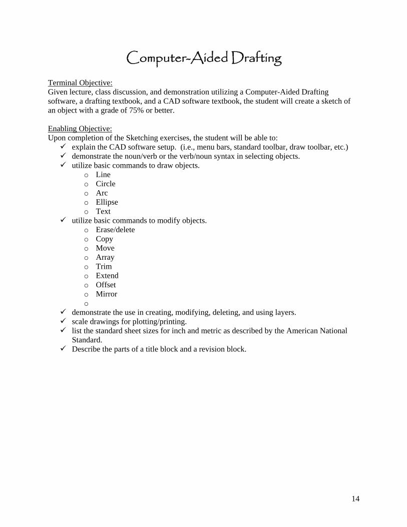
Computer-Aided Drafting Terminal Objective: Given lecture, class discussion, and demonstration utilizing a Computer-Aided Drafting software, a drafting textbook, and a CAD software textbook, the student will create a sketch of an object with a grade of 75% or better. Enabling Objective: Upon completion of the Sketching exercises, the student will be able to:
explain the CAD software setup. (i.e., menu bars, standard toolbar, draw toolbar, etc.) demonstrate the noun/verb or the verb/noun syntax in selecting objects. utilize basic commands to draw objects.
o Line o Circle o Arc o Ellipse o Text
utilize basic commands to modify objects. o Erase/delete o Copy o Move o Array o Trim o Extend o Offset o Mirror o
demonstrate the use in creating, modifying, deleting, and using layers. scale drawings for plotting/printing. list the standard sheet sizes for inch and metric as described by the American National
Standard. Describe the parts of a title block and a revision block.
15
CAD Drawing:
16
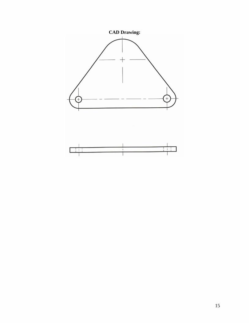
Orthographic and Multiview Projection Terminal Objective: Given lecture, class discussion, and demonstration utilizing PowerPoint, a drafting textbook, 0.9mm, 0.7mm, 0.5mm, and 0.3mm mechanical pencils, the student will create a sketch and a computer-aided drawing of an object in orthographic (6 views) and multiview (3 views) with a grade of 75% or better. Enabling Objective: Upon completion of the Sketching exercises, the student will be able to:
create sketches and computer-aided drawings of an object using orthographic (6 views) projection.
create sketches and computer-aided drawings of an object using multiview (3 views) projection.
apply the alphabet of lines as defined by the feature drawn. create proportional views of the object. apply sketching techniques as defined by ASME Y14.5. identify placement of lines at intersections and tangencies. identify fillets and rounds. demonstrate the representation of a drilled through, blind, counterbored, and countersunk
holes. create a runout. explain the difference between First-Angle and Third-Angle projection. demonstrate the use of a miter line. transfer features from one view to another. identify the planes of projection.
Orthographic Projection:
17
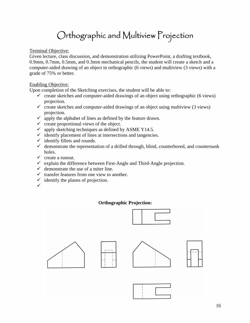
Multiview Projection:
18
Oblique and Axonometric Projection Terminal Objective: Given lecture, class discussion, and demonstration utilizing PowerPoint, a drafting textbook, 0.9mm, 0.7mm, 0.5mm, and 0.3mm mechanical pencils, and computer-aided drawing software, the student will create a sketch and a computer-aided oblique and an axonometric (isometric, dimetric, and trimetric) drawing of an object with a grade of 75% or better. Enabling Objective: Upon completion of the Sketching exercises, the student will be able to:
create sketches and computer-aided drawings of an object using oblique projection. create sketches and computer-aided drawings of an object using axonometric (isometric,
dimetric, and trimetric) projection. apply the alphabet of lines according to the line type drawn. create proportional views of the object. apply sketching techniques as defined by ASME Y14.5.
19
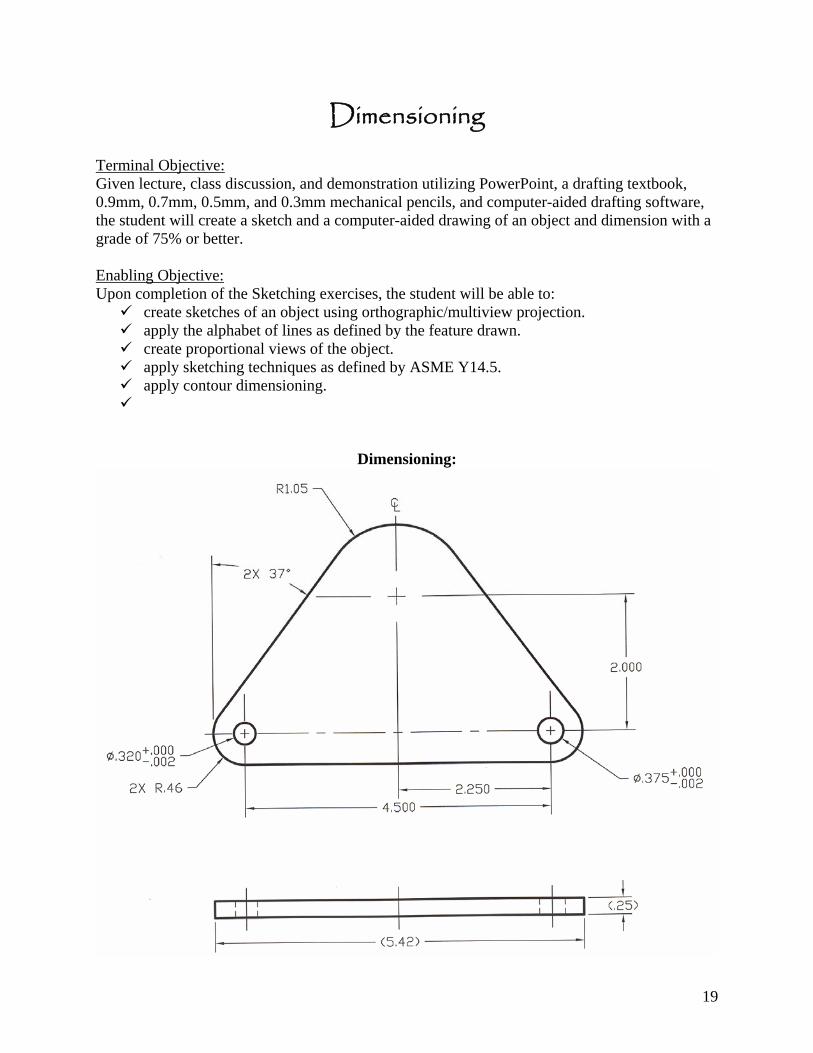
Dimensioning Terminal Objective: Given lecture, class discussion, and demonstration utilizing PowerPoint, a drafting textbook, 0.9mm, 0.7mm, 0.5mm, and 0.3mm mechanical pencils, and computer-aided drafting software, the student will create a sketch and a computer-aided drawing of an object and dimension with a grade of 75% or better. Enabling Objective: Upon completion of the Sketching exercises, the student will be able to:
create sketches of an object using orthographic/multiview projection. apply the alphabet of lines as defined by the feature drawn. create proportional views of the object. apply sketching techniques as defined by ASME Y14.5. apply contour dimensioning.
Dimensioning:
20
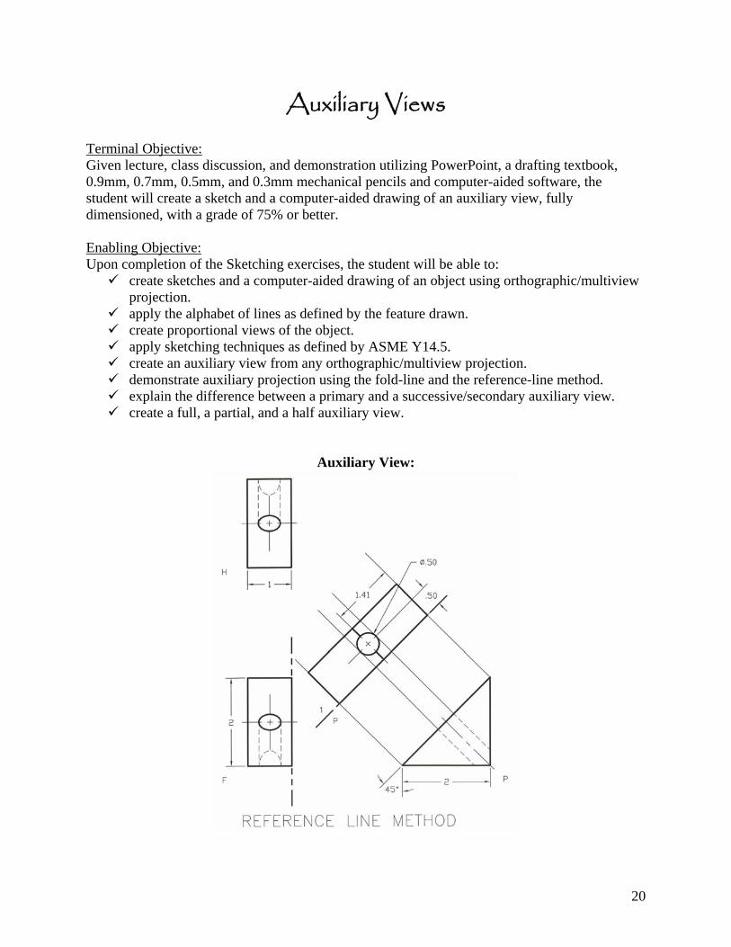
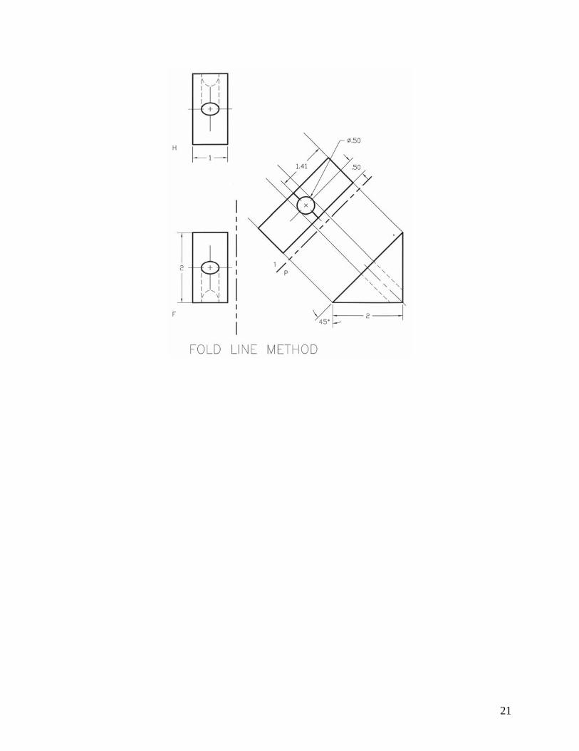
Auxiliary Views Terminal Objective: Given lecture, class discussion, and demonstration utilizing PowerPoint, a drafting textbook, 0.9mm, 0.7mm, 0.5mm, and 0.3mm mechanical pencils and computer-aided software, the student will create a sketch and a computer-aided drawing of an auxiliary view, fully dimensioned, with a grade of 75% or better. Enabling Objective: Upon completion of the Sketching exercises, the student will be able to:
create sketches and a computer-aided drawing of an object using orthographic/multiview projection.
apply the alphabet of lines as defined by the feature drawn. create proportional views of the object. apply sketching techniques as defined by ASME Y14.5. create an auxiliary view from any orthographic/multiview projection. demonstrate auxiliary projection using the fold-line and the reference-line method. explain the difference between a primary and a successive/secondary auxiliary view. create a full, a partial, and a half auxiliary view.
Auxiliary View:
21
22
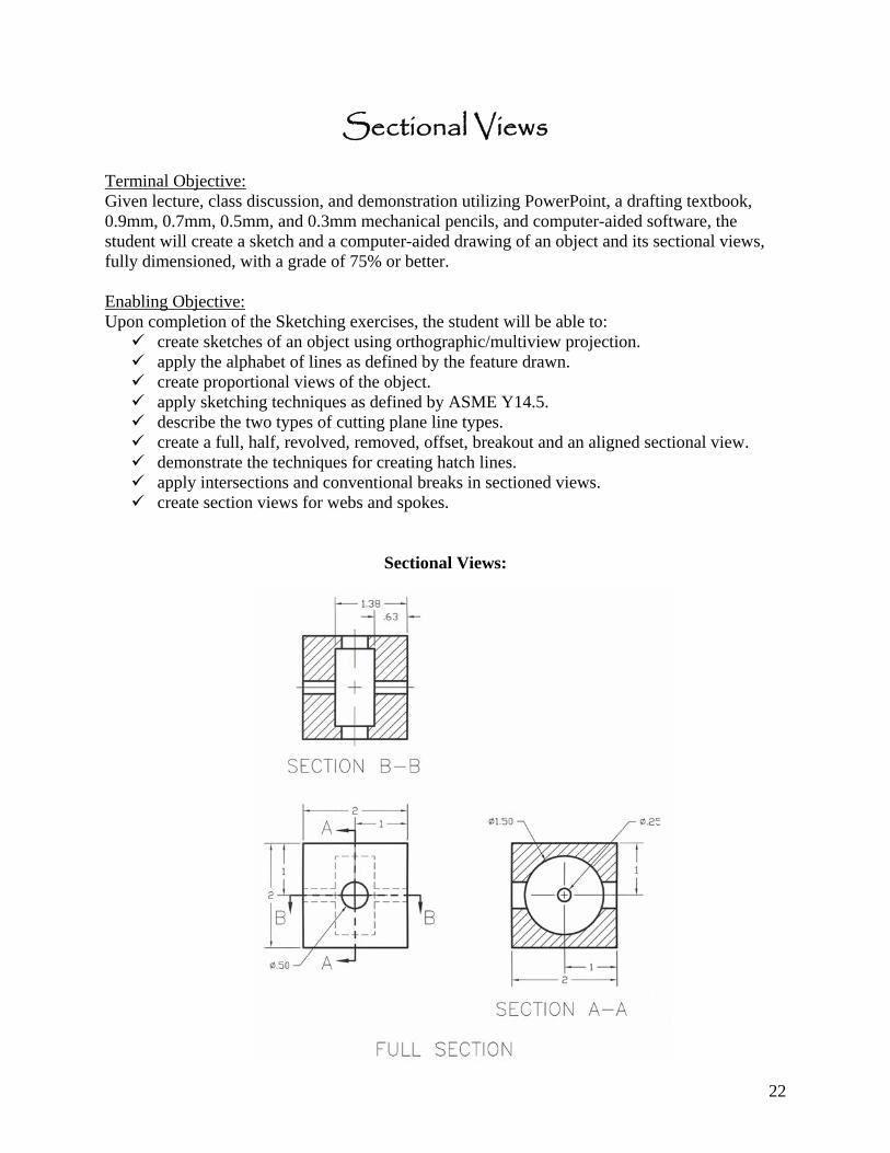
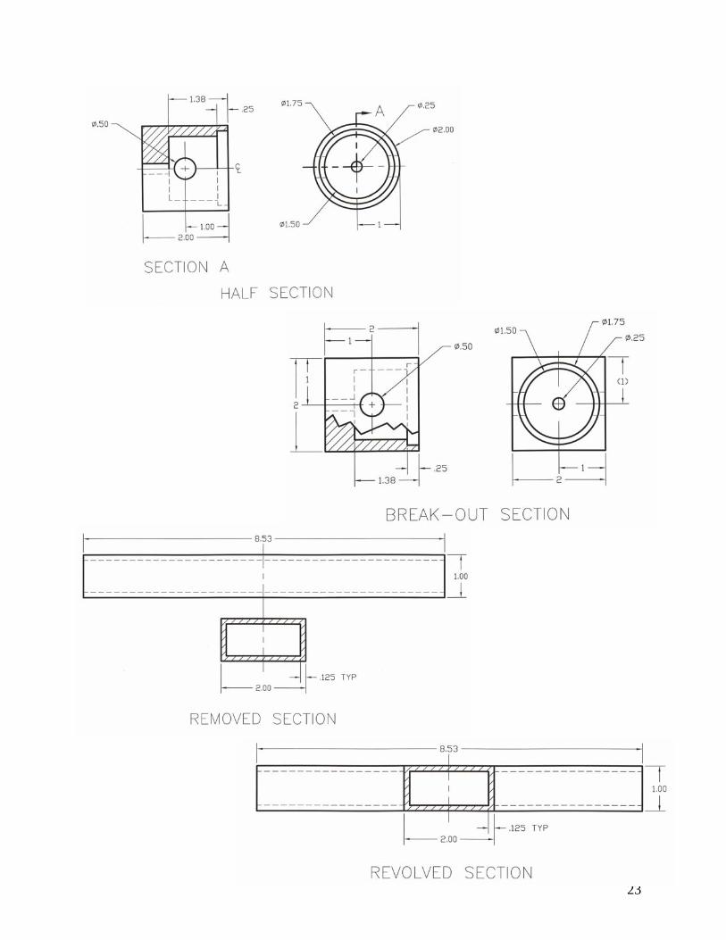
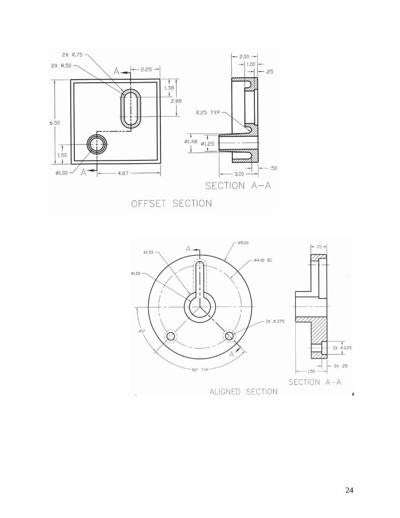
Sectional Views Terminal Objective: Given lecture, class discussion, and demonstration utilizing PowerPoint, a drafting textbook, 0.9mm, 0.7mm, 0.5mm, and 0.3mm mechanical pencils, and computer-aided software, the student will create a sketch and a computer-aided drawing of an object and its sectional views, fully dimensioned, with a grade of 75% or better. Enabling Objective: Upon completion of the Sketching exercises, the student will be able to:
create sketches of an object using orthographic/multiview projection. apply the alphabet of lines as defined by the feature drawn. create proportional views of the object. apply sketching techniques as defined by ASME Y14.5. describe the two types of cutting plane line types. create a full, half, revolved, removed, offset, breakout and an aligned sectional view. demonstrate the techniques for creating hatch lines. apply intersections and conventional breaks in sectioned views. create section views for webs and spokes.
Sectional Views:
23
24
25
Glossary of Terms Term Definition
ANSI American National Standards Institute
Application A computer program. A CAD application can carryout extremely complex tasks specific to a particular drawing problem. CAD applications run in tandem with the CAD software to perform specialized or automated tasks. Some examples of CAD applications specific to theatre include programs to automate the drawing of construction drawings and light plots.
Array To create automatically on a CAD system an arrangement of identical elements or components. The designer defines the element once, then indicates the starting location and spacing for automatic generation of the array. Can be done rectangular (rows and columns) or polar (circular).
Arrowhead The part of a dimension or leader, which points to an object or extension line. Arrowheads usually can be drawn automatically in several styles or shapes.
ASCII American Standard Code for Informational Interchange. An industry standard character code widely used for information interchange among data processing systems, communication systems, and associated equipment.
Attribute Information or data about a drawing object which can be hidden or appear in the drawing as text. Often this information can be extracted from the drawing and used in a spreadsheet or other program.
Bezier curve A curve defined by endpoints, tangent lines, and control points at the ends of the tangent lines. Altering the length and angle of tangent lines alters the shape of the curve.
Bitmap A pixel based graphic or image inserted in a drawing. Bitmaps can be sized but not edited with most CAD programs. block (AutoCAD terminology), see symbol.
CAD Computer-aided design. Common CAD programs include: Generic CADD (DOS), AutoCAD (DOS and Windows), Claris CAD (Mac), MiniCAD (Mac), DesignCAD (DOS and Windows), Drafix CAD (Windows) and Visual CADD (Windows). Programs differ greatly in features, complexity, cost, and hardware requirements.
CADD Computer-aided design and drafting.
Cartesian coordinates See coordinates.
26
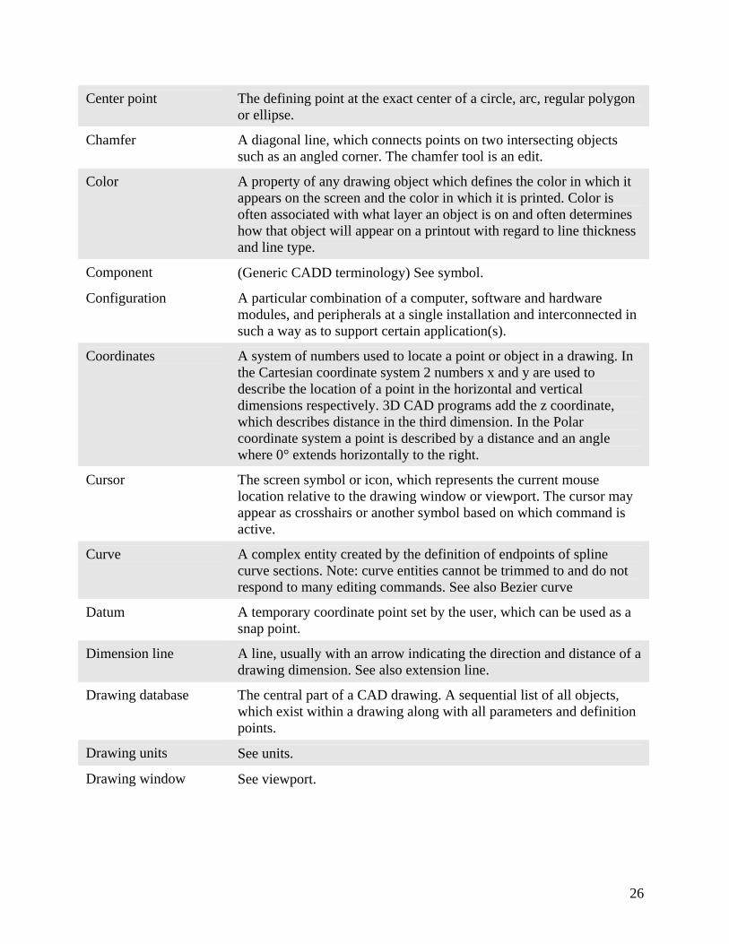
Center point The defining point at the exact center of a circle, arc, regular polygon or ellipse.
Chamfer A diagonal line, which connects points on two intersecting objects such as an angled corner. The chamfer tool is an edit.
Color A property of any drawing object which defines the color in which it appears on the screen and the color in which it is printed. Color is often associated with what layer an object is on and often determines how that object will appear on a printout with regard to line thickness and line type.
Component (Generic CADD terminology) See symbol.
Configuration A particular combination of a computer, software and hardware modules, and peripherals at a single installation and interconnected in such a way as to support certain application(s).
Coordinates A system of numbers used to locate a point or object in a drawing. In the Cartesian coordinate system 2 numbers x and y are used to describe the location of a point in the horizontal and vertical dimensions respectively. 3D CAD programs add the z coordinate, which describes distance in the third dimension. In the Polar coordinate system a point is described by a distance and an angle where 0° extends horizontally to the right.
Cursor The screen symbol or icon, which represents the current mouse location relative to the drawing window or viewport. The cursor may appear as crosshairs or another symbol based on which command is active.
Curve A complex entity created by the definition of endpoints of spline curve sections. Note: curve entities cannot be trimmed to and do not respond to many editing commands. See also Bezier curve
Datum A temporary coordinate point set by the user, which can be used as a snap point.
Dimension line A line, usually with an arrow indicating the direction and distance of a drawing dimension. See also extension line.
Drawing database The central part of a CAD drawing. A sequential list of all objects, which exist within a drawing along with all parameters and definition points.
Drawing units See units.
Drawing window See viewport.
27
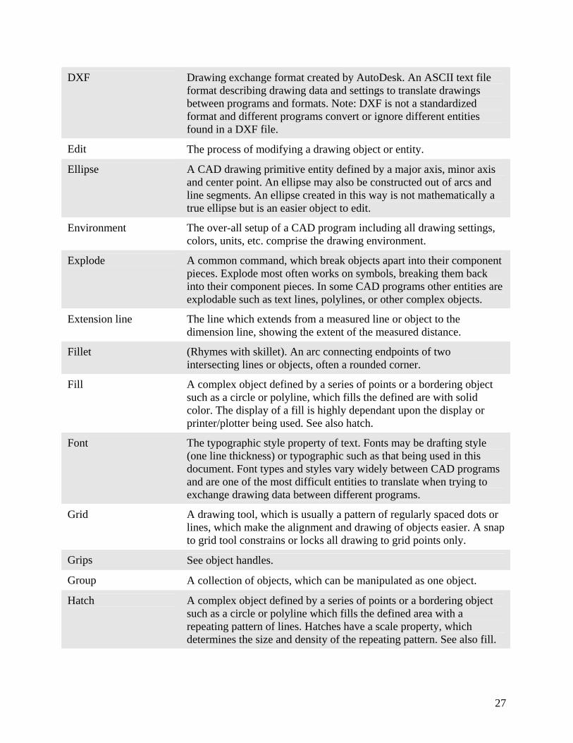
DXF Drawing exchange format created by AutoDesk. An ASCII text file format describing drawing data and settings to translate drawings between programs and formats. Note: DXF is not a standardized format and different programs convert or ignore different entities found in a DXF file.
Edit The process of modifying a drawing object or entity.
Ellipse A CAD drawing primitive entity defined by a major axis, minor axis and center point. An ellipse may also be constructed out of arcs and line segments. An ellipse created in this way is not mathematically a true ellipse but is an easier object to edit.
Environment The over-all setup of a CAD program including all drawing settings, colors, units, etc. comprise the drawing environment.
Explode A common command, which break objects apart into their component pieces. Explode most often works on symbols, breaking them back into their component pieces. In some CAD programs other entities are explodable such as text lines, polylines, or other complex objects.
Extension line The line which extends from a measured line or object to the dimension line, showing the extent of the measured distance.
Fillet (Rhymes with skillet). An arc connecting endpoints of two intersecting lines or objects, often a rounded corner.
Fill A complex object defined by a series of points or a bordering object such as a circle or polyline, which fills the defined are with solid color. The display of a fill is highly dependant upon the display or printer/plotter being used. See also hatch.
Font The typographic style property of text. Fonts may be drafting style (one line thickness) or typographic such as that being used in this document. Font types and styles vary widely between CAD programs and are one of the most difficult entities to translate when trying to exchange drawing data between different programs.
Grid A drawing tool, which is usually a pattern of regularly spaced dots or lines, which make the alignment and drawing of objects easier. A snap to grid tool constrains or locks all drawing to grid points only.
Grips See object handles.
Group A collection of objects, which can be manipulated as one object.
Hatch A complex object defined by a series of points or a bordering object such as a circle or polyline which fills the defined area with a repeating pattern of lines. Hatches have a scale property, which determines the size and density of the repeating pattern. See also fill.
28
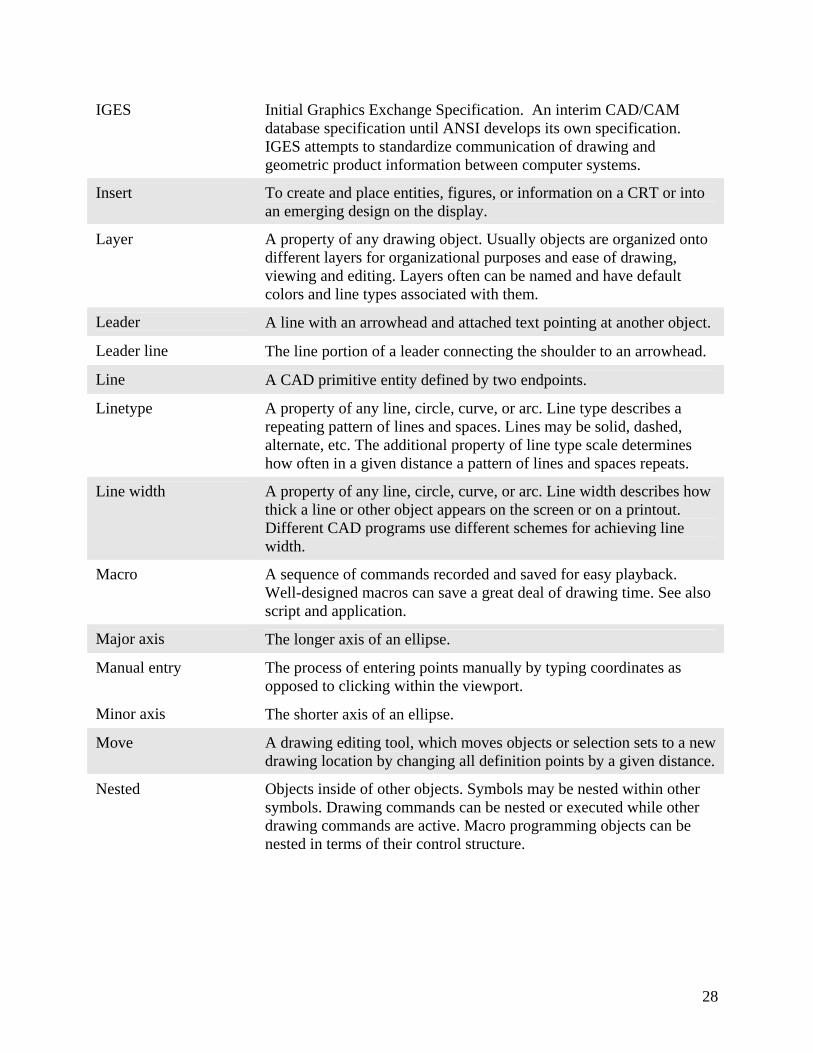
IGES Initial Graphics Exchange Specification. An interim CAD/CAM database specification until ANSI develops its own specification. IGES attempts to standardize communication of drawing and geometric product information between computer systems.
Insert To create and place entities, figures, or information on a CRT or into an emerging design on the display.
Layer A property of any drawing object. Usually objects are organized onto different layers for organizational purposes and ease of drawing, viewing and editing. Layers often can be named and have default colors and line types associated with them.
Leader A line with an arrowhead and attached text pointing at another object.
Leader line The line portion of a leader connecting the shoulder to an arrowhead.
Line A CAD primitive entity defined by two endpoints.
Linetype A property of any line, circle, curve, or arc. Line type describes a repeating pattern of lines and spaces. Lines may be solid, dashed, alternate, etc. The additional property of line type scale determines how often in a given distance a pattern of lines and spaces repeats.
Line width A property of any line, circle, curve, or arc. Line width describes how thick a line or other object appears on the screen or on a printout. Different CAD programs use different schemes for achieving line width.
Macro A sequence of commands recorded and saved for easy playback. Well-designed macros can save a great deal of drawing time. See also script and application.
Major axis The longer axis of an ellipse.
Manual entry The process of entering points manually by typing coordinates as opposed to clicking within the viewport.
Minor axis The shorter axis of an ellipse.
Move A drawing editing tool, which moves objects or selection sets to a new drawing location by changing all definition points by a given distance.
Nested Objects inside of other objects. Symbols may be nested within other symbols. Drawing commands can be nested or executed while other drawing commands are active. Macro programming objects can be nested in terms of their control structure.
29
Object handles In a windows CAD program the handles, which appear when an object is selected. Handles often allow objects to be stretched, rotated, or moved. Note: in AutoCAD handles refer to arbitrary names assigned to each drawing entity in the drawing database so that macros and applications may refer to specific entities directly.
Offset The distance between two objects. Offsets are often used to draw parallel lines or determine the location of a dimension. In AutoCAD a command which creates a duplicate of an object at a specified distance.
Origin The point in a drawing with the X,Y coordinates of 0,0.
Ortho Short for orthagonal. Usually refers to objects placed horizontally or vertically within a drawing. Ortho mode is a constraint, which limits all drawing to regular 90° angles. In some CAD programs other ortho angles and modes may be set.
Pan The process of altering the drawing view by moving the viewpoint laterally relative to the drawing.
Plotter A CAD peripheral device used to output for external use the image stored in the database. Generally makes large, accurate drawings substantially better than what is displayed. Plotter types include pen, drum, electrostatic, flat bed, and inkjet.
Polar coordinates See coordinates.
Polygon A complex object composed of three or more straight lines in a closed figure. Different CAD programs treat polygons differently. Often a polygon is simply a closed polyline entity.
Polyline A complex object composed of two or more lines, curves, or arcs, which have contiguous endpoints. A closed polyline or polygon has its endpoints joined into a closed form. Polylines are more difficult to edit than a form drawn with individual line segments, but offers some advantages when editing or building surfaces and 3 dimensional objects.
Precision The degree of accuracy. Generally refers to the number of significant digits of information to the right of the decimal point for data represented within a computer system. Thus, the term denoted the degree of discrimination with which a design or design element can be described in the database.
Primitive The simplest drawing entities from which all objects are built. Common primitives include: point, line, circle, arc, and ellipse.
Prompt A program message often located on the programs status line.
Real scale Objects in a CAD program a drawn at full scale or 1:1. See scale.
30
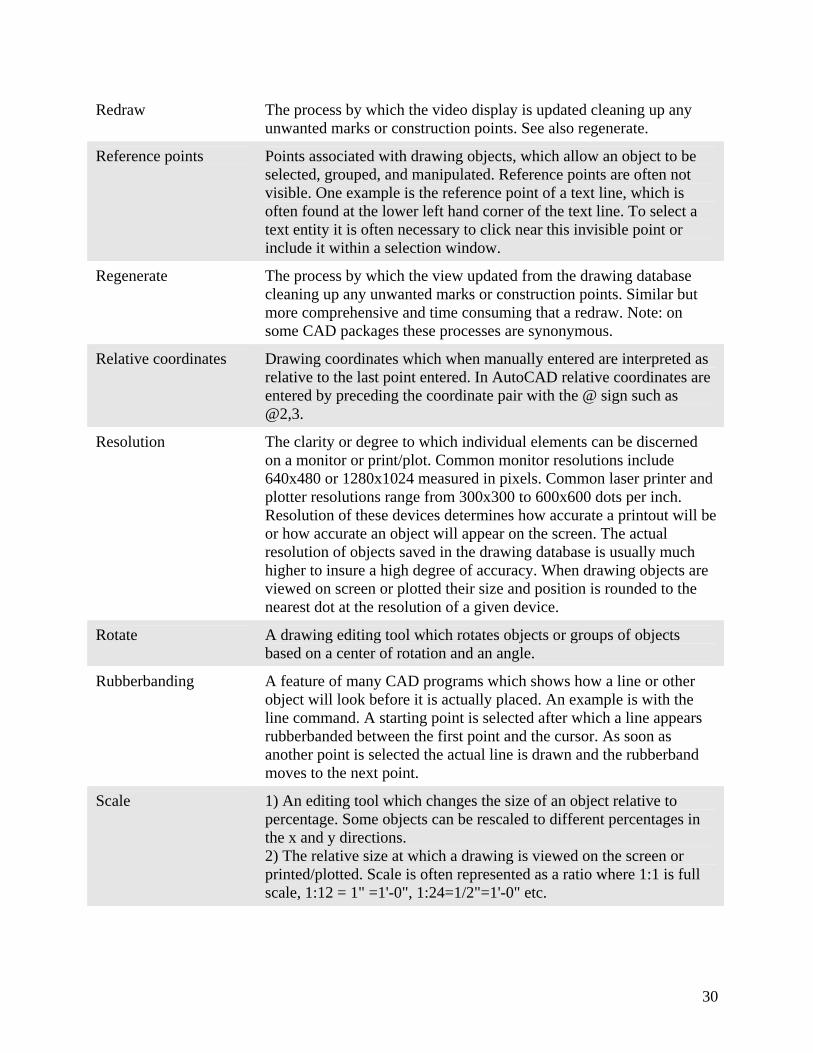
Redraw The process by which the video display is updated cleaning up any unwanted marks or construction points. See also regenerate.
Reference points Points associated with drawing objects, which allow an object to be selected, grouped, and manipulated. Reference points are often not visible. One example is the reference point of a text line, which is often found at the lower left hand corner of the text line. To select a text entity it is often necessary to click near this invisible point or include it within a selection window.
Regenerate The process by which the view updated from the drawing database cleaning up any unwanted marks or construction points. Similar but more comprehensive and time consuming that a redraw. Note: on some CAD packages these processes are synonymous.
Relative coordinates Drawing coordinates which when manually entered are interpreted as relative to the last point entered. In AutoCAD relative coordinates are entered by preceding the coordinate pair with the @ sign such as @2,3.
Resolution The clarity or degree to which individual elements can be discerned on a monitor or print/plot. Common monitor resolutions include 640x480 or 1280x1024 measured in pixels. Common laser printer and plotter resolutions range from 300x300 to 600x600 dots per inch. Resolution of these devices determines how accurate a printout will be or how accurate an object will appear on the screen. The actual resolution of objects saved in the drawing database is usually much higher to insure a high degree of accuracy. When drawing objects are viewed on screen or plotted their size and position is rounded to the nearest dot at the resolution of a given device.
Rotate A drawing editing tool which rotates objects or groups of objects based on a center of rotation and an angle.
Rubberbanding A feature of many CAD programs which shows how a line or other object will look before it is actually placed. An example is with the line command. A starting point is selected after which a line appears rubberbanded between the first point and the cursor. As soon as another point is selected the actual line is drawn and the rubberband moves to the next point.
Scale 1) An editing tool which changes the size of an object relative to percentage. Some objects can be rescaled to different percentages in the x and y directions. 2) The relative size at which a drawing is viewed on the screen or printed/plotted. Scale is often represented as a ratio where 1:1 is full scale, 1:12 = 1" =1'-0", 1:24=1/2"=1'-0" etc.
31
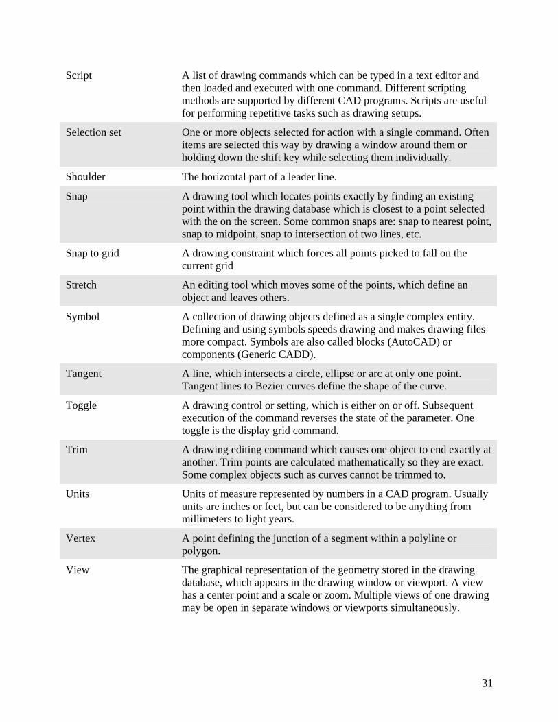
Script A list of drawing commands which can be typed in a text editor and then loaded and executed with one command. Different scripting methods are supported by different CAD programs. Scripts are useful for performing repetitive tasks such as drawing setups.
Selection set One or more objects selected for action with a single command. Often items are selected this way by drawing a window around them or holding down the shift key while selecting them individually.
Shoulder The horizontal part of a leader line.
Snap A drawing tool which locates points exactly by finding an existing point within the drawing database which is closest to a point selected with the on the screen. Some common snaps are: snap to nearest point, snap to midpoint, snap to intersection of two lines, etc.
Snap to grid A drawing constraint which forces all points picked to fall on the current grid
Stretch An editing tool which moves some of the points, which define an object and leaves others.
Symbol A collection of drawing objects defined as a single complex entity. Defining and using symbols speeds drawing and makes drawing files more compact. Symbols are also called blocks (AutoCAD) or components (Generic CADD).
Tangent A line, which intersects a circle, ellipse or arc at only one point. Tangent lines to Bezier curves define the shape of the curve.
Toggle A drawing control or setting, which is either on or off. Subsequent execution of the command reverses the state of the parameter. One toggle is the display grid command.
Trim A drawing editing command which causes one object to end exactly at another. Trim points are calculated mathematically so they are exact. Some complex objects such as curves cannot be trimmed to.
Units Units of measure represented by numbers in a CAD program. Usually units are inches or feet, but can be considered to be anything from millimeters to light years.
Vertex A point defining the junction of a segment within a polyline or polygon.
View The graphical representation of the geometry stored in the drawing database, which appears in the drawing window or viewport. A view has a center point and a scale or zoom. Multiple views of one drawing may be open in separate windows or viewports simultaneously.

32
Viewport The window or frame within which a view of the drawing is visible. In some complex CAD programs viewports are considered complex objects and can be placed in drawings. Many programs also support the use of multiple viewports, which can simultaneously show different parts of the same drawing. This is especially important when working in 3D.
Zoom The way the view is changed by magnifying or reducing the image on the screen. Zoom scales the view only and does not affect the actual size of drawing objects.
33
Appendix Information in this manual can be obtained from the following sources. Baartmans, B. G., & Sorby, S. A. (1996). Introduction to 3-D spatial
visualization. Englewood Cliffs, NJ: Prentice Hall.
Bertoline, G. R., Wiebe, E. N., Miller, C. L., & Mohler, J. L., (1997). Technical
graphics communication (2nd ed.). Chicago: McGraw-Hill.
Craig, J. W., & Craig, O. B., (1999). Engineering graphics text and workbook
(2nd ed). Mission, KS: Schroff Development Corporation.
Croft, F. M., Meyers, F. D., Boyer, E. T., Miller, M. J., & Demel, J. T. (1989).
Engineering graphics. New York: Wiley.
Giesecke, F. E., Mitchell, A., Spencer, H. C., Hill, I. L., Dygdon, J. T., & Novak,
J. E. (2002). Technical drawing (12th ed.). Upper Saddle River, NJ:
Pearson Education.
Goetsch, D. L., Nelson, J. A., & Chalk, W. S. (2000). Technical drawing (4th
ed.). Albany: Delmar.
Jensen, C., Helsel, J. D., & Short, D. R. (2002). Engineering Drawing and
Design (6th ed). New York, NY: McGraw-Hill.
Madsen, D. A., Folkestad, J., Schertz, K. A., Shumaker, T. M., Stark, C., &
Turpin, J. L. (2002). Engineering drawing and design (3rd ed.). Albany:
Delmar.
Quinlan, C. (1996). Orthographic Projection Simplified (5th ed). New York, NY:
McGraw-Hill.
Sorby, S. (2003). Introduction to 3D spatial visualization: An active approach.
Clifton Park, NY: Delmar Learning.
Sorby, S. A., Manner, K. J., & Baartmans, B. J. (1998). 3-D visualization for
engineering graphics. Upper Saddle River, NJ: Prentice Hall.


![DEPARTMENT OF ENERGY [AU-RM-16-WSHP] RIN 1992 … · ASME B31.8-2016, Gas Transmission and Distribution Piping Systems, ASME Code for Pressure Piping, ... G. Review Under the Unfunded](https://img.pdfslide.us/doc/110x75/5ad675e17f8b9a075a8e3de1/department-of-energy-au-rm-16-wshp-rin-1992-b318-2016-gas-transmission-and.jpg)