Embed Size (px)
Citation preview
Mark Thomson
The ILD Letter of Intent:Optimisation and Performance
for the ILD group
IntroductionOptimisation of ILD(GLD/LDC ILD)
PerformanceConclusions
This talk:
TILC09, Tsukuba, 17/04/2009 Mark Thomson 2
Introduction
ILC provides a clean environment for high precision measurementsOptimise detector to take full advantage of ILC Requires high precision/high efficiency trackingExcellent vertex tagging capabilitiesUnprecedented jet energy resolution
Design Requirements
International Large Detector: PhilosophyBased on high granularity particle flow calorimetry
• confident this will provide necessary jet energy resolution“Large” central Time Projection Chamber (TPC)
• proven technology; provides excellent pattern recognition in a dense track environment
Tracking augmented by Si strip/pixels• extend tracking coverage + improves precision
A high precision Vertex detector close to IP• for best possible heavy flavour tagging
Close to 4π tracking/calorimetric acceptance
TILC09, Tsukuba, 17/04/2009 Mark Thomson 3
From GLD/LDC to ILD
Late 2007: ILD formed from previous (Asian-dominated) GLD and (European-dominated) LDC groups
History
Jan 2008: first ILD meeting (DESY Zeuthen)Sep 2008: ILD baseline parameters chosen
• not always an easy process - required compromises• choices based on physics arguments from extensive studies
(the first part of this talk) • essentially unanimous agreement !
Mar 2009: ILD Letter of Intent submitted, including• current understanding of ILD performance• wide range of physics studies
the second part of this talk
Huge amount of work by many people !Today I can only give a summary…For more details see LoI, supporting documents and parallel session talks
TILC09, Tsukuba, 17/04/2009 Mark Thomson 4
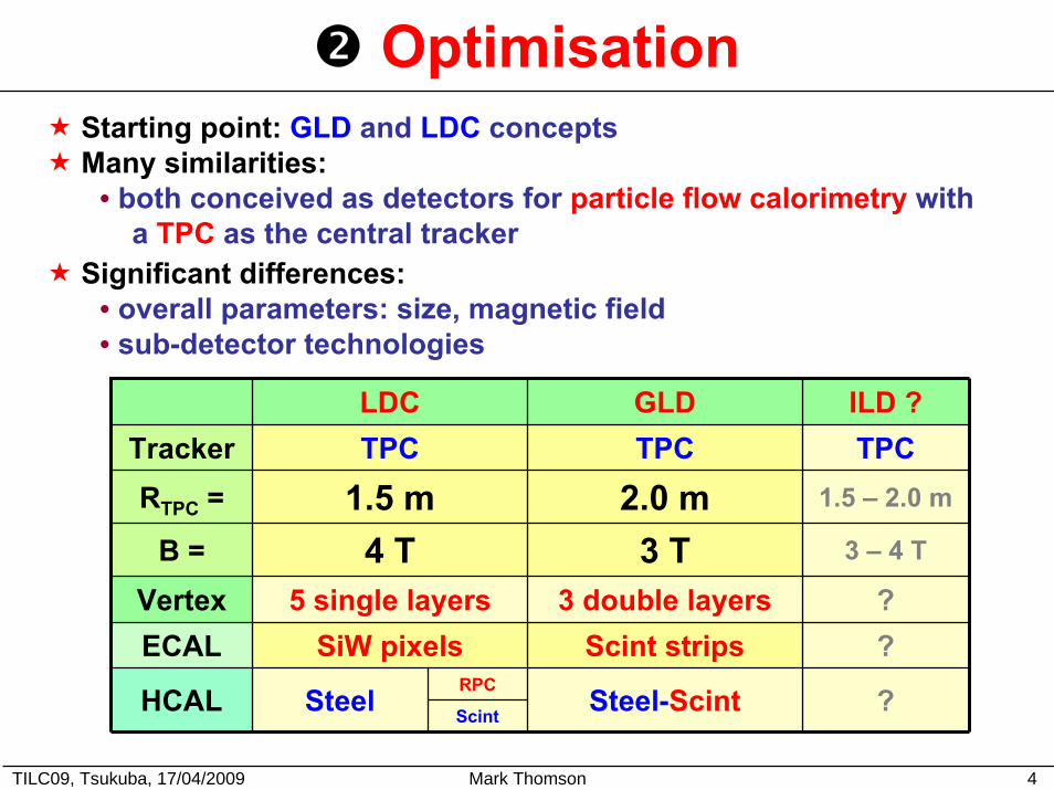
OptimisationStarting point: GLD and LDC conceptsMany similarities:
• both conceived as detectors for particle flow calorimetry with a TPC as the central tracker
Significant differences:• overall parameters: size, magnetic field• sub-detector technologies
LDC GLDTPC TPC
2.0 m3 T
Vertex 5 single layers 3 double layers ?Scint strips
Steel-Scint
1.5 m4 T
SiW pixels
Steel
Tracker TPC
B = 3 – 4 T
ECAL ?RPC
RTPC =
HCAL
ILD ?
1.5 – 2.0 m
Scint ?
TILC09, Tsukuba, 17/04/2009 Mark Thomson 5
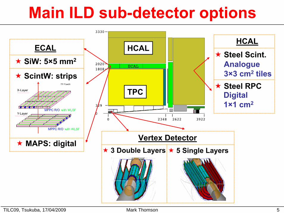
Main ILD sub-detector options
TPC
HCALSiW: 5×5 mm2
ScintW: strips
MAPS: digital
ECAL
3 Double Layers 5 Single Layers
Vertex Detector
HCALSteel Scint.Analogue3×3 cm2 tilesSteel RPCDigital1×1 cm2
TILC09, Tsukuba, 17/04/2009 Mark Thomson 6
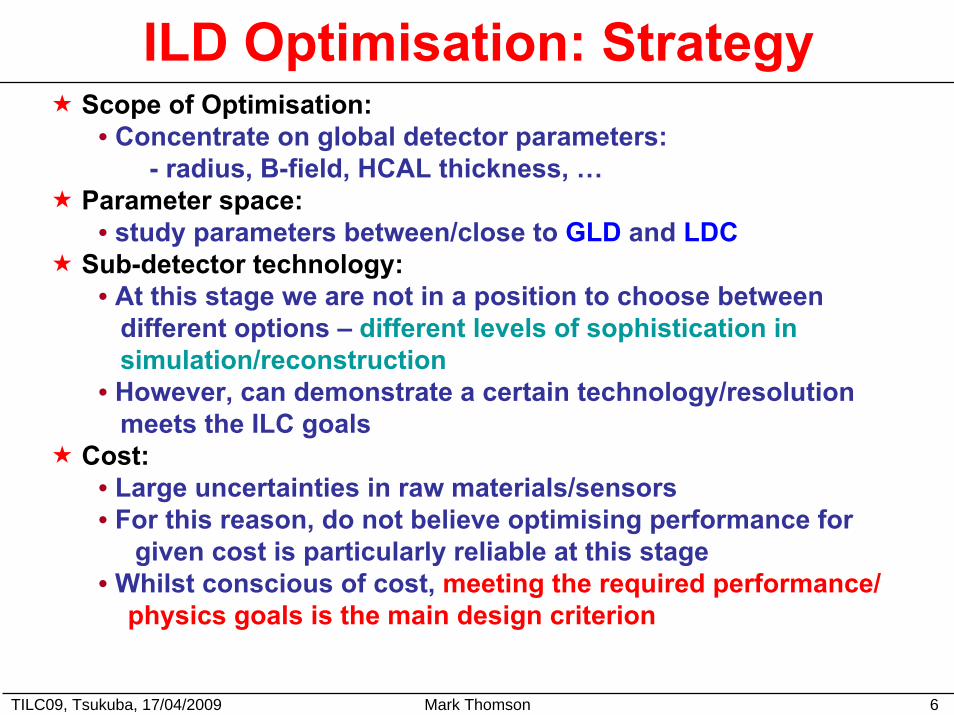
ILD Optimisation: Strategy Scope of Optimisation:
• Concentrate on global detector parameters:- radius, B-field, HCAL thickness, …
Parameter space:• study parameters between/close to GLD and LDC
Sub-detector technology:• At this stage we are not in a position to choose between
different options – different levels of sophistication insimulation/reconstruction
• However, can demonstrate a certain technology/resolution meets the ILC goals
Cost:• Large uncertainties in raw materials/sensors• For this reason, do not believe optimising performance for
given cost is particularly reliable at this stage • Whilst conscious of cost, meeting the required performance/
physics goals is the main design criterion
TILC09, Tsukuba, 17/04/2009 Mark Thomson 7
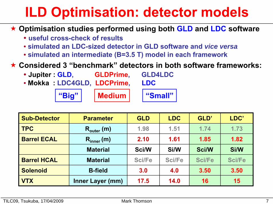
ILD Optimisation: detector modelsOptimisation studies performed using both GLD and LDC software
• useful cross-check of results• simulated an LDC-sized detector in GLD software and vice versa• simulated an intermediate (B=3.5 T) model in each framework
Considered 3 “benchmark” detectors in both software frameworks: • Jupiter : GLD, GLDPrime, GLD4LDC• Mokka : LDC4GLD, LDCPrime, LDC
Sub-Detector Parameter GLD LDC GLD’ LDC’TPC Router (m) 1.98 1.51 1.74 1.73Barrel ECAL Rinner (m) 2.10 1.61 1.85 1.82
Material Sci/W Si/W Sci/W Si/WBarrel HCAL Material Sci/Fe Sci/Fe Sci/Fe Sci/FeSolenoid B-field 3.0 4.0 3.50 3.50VTX Inner Layer (mm) 17.5 14.0 16 15
“Big” Medium “Small”
TILC09, Tsukuba, 17/04/2009 Mark Thomson 8
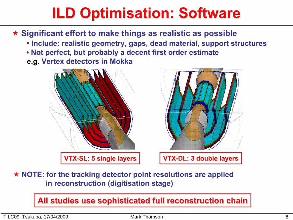
ILD Optimisation: SoftwareSignificant effort to make things as realistic as possible
• Include: realistic geometry, gaps, dead material, support structures• Not perfect, but probably a decent first order estimate e.g. Vertex detectors in Mokka
VTX-DL: 3 double layersVTX-SL: 5 single layers
NOTE: for the tracking detector point resolutions are applied in reconstruction (digitisation stage)
All studies use sophisticated full reconstruction chain
TILC09, Tsukuba, 17/04/2009 Mark Thomson 9
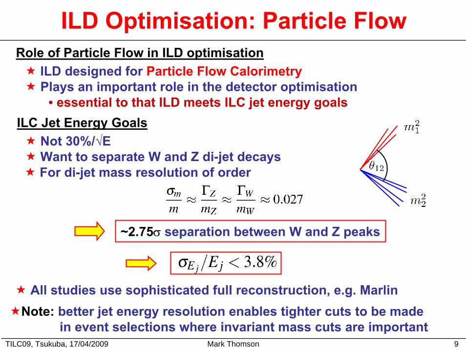
ILD Optimisation: Particle Flow
ILD designed for Particle Flow CalorimetryPlays an important role in the detector optimisation
• essential to that ILD meets ILC jet energy goals
Role of Particle Flow in ILD optimisation
ILC Jet Energy GoalsNot 30%/√E Want to separate W and Z di-jet decaysFor di-jet mass resolution of order
~2.75σ separation between W and Z peaks
All studies use sophisticated full reconstruction, e.g. MarlinNote: better jet energy resolution enables tighter cuts to be made
in event selections where invariant mass cuts are important
TILC09, Tsukuba, 17/04/2009 Mark Thomson 10
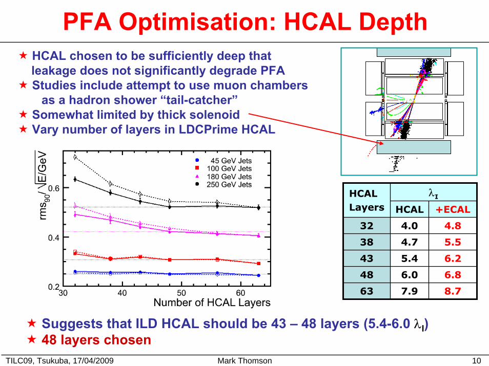
PFA Optimisation: HCAL DepthHCAL chosen to be sufficiently deep that leakage does not significantly degrade PFAStudies include attempt to use muon chambers
as a hadron shower “tail-catcher”Somewhat limited by thick solenoidVary number of layers in LDCPrime HCAL
λIHCALLayers HCAL +ECAL
32 4.0 4.8
38 4.7 5.5
43 5.4 6.2
48 6.0 6.8
63 7.9 8.7
Suggests that ILD HCAL should be 43 – 48 layers (5.4-6.0 λI)48 layers chosen
TILC09, Tsukuba, 17/04/2009 Mark Thomson 11
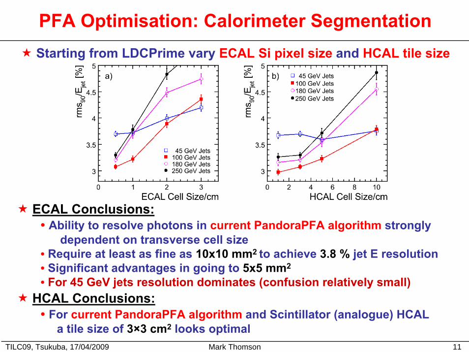
PFA Optimisation: Calorimeter SegmentationStarting from LDCPrime vary ECAL Si pixel size and HCAL tile size
ECAL Conclusions: • Ability to resolve photons in current PandoraPFA algorithm strongly
dependent on transverse cell size• Require at least as fine as 10x10 mm2 to achieve 3.8 % jet E resolution• Significant advantages in going to 5x5 mm2
• For 45 GeV jets resolution dominates (confusion relatively small)HCAL Conclusions:
• For current PandoraPFA algorithm and Scintillator (analogue) HCALa tile size of 3×3 cm2 looks optimal
TILC09, Tsukuba, 17/04/2009 Mark Thomson 12
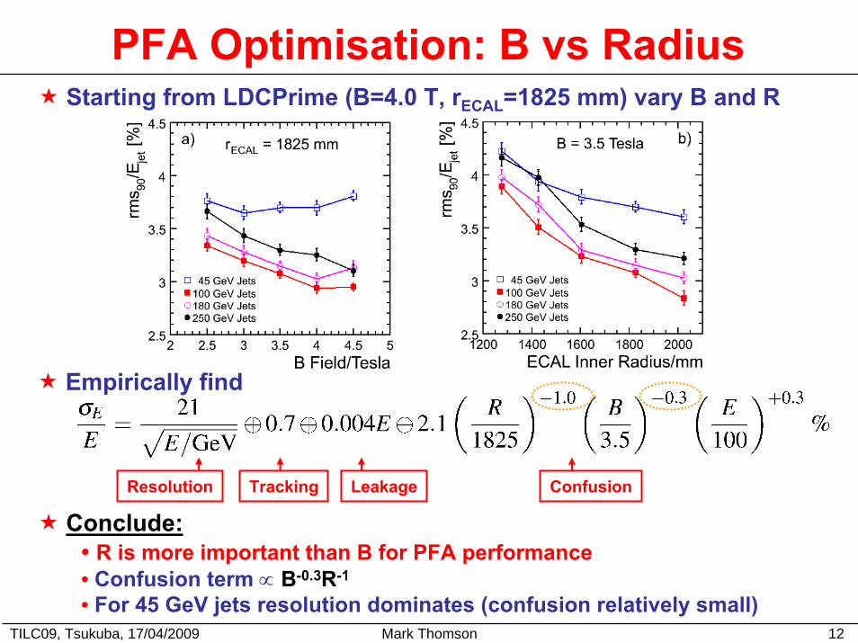
PFA Optimisation: B vs RadiusStarting from LDCPrime (B=4.0 T, rECAL=1825 mm) vary B and R
Empirically find
Resolution Tracking Leakage Confusion
Conclude:• R is more important than B for PFA performance• Confusion term ∝ B-0.3R-1
• For 45 GeV jets resolution dominates (confusion relatively small)
TILC09, Tsukuba, 17/04/2009 Mark Thomson 13
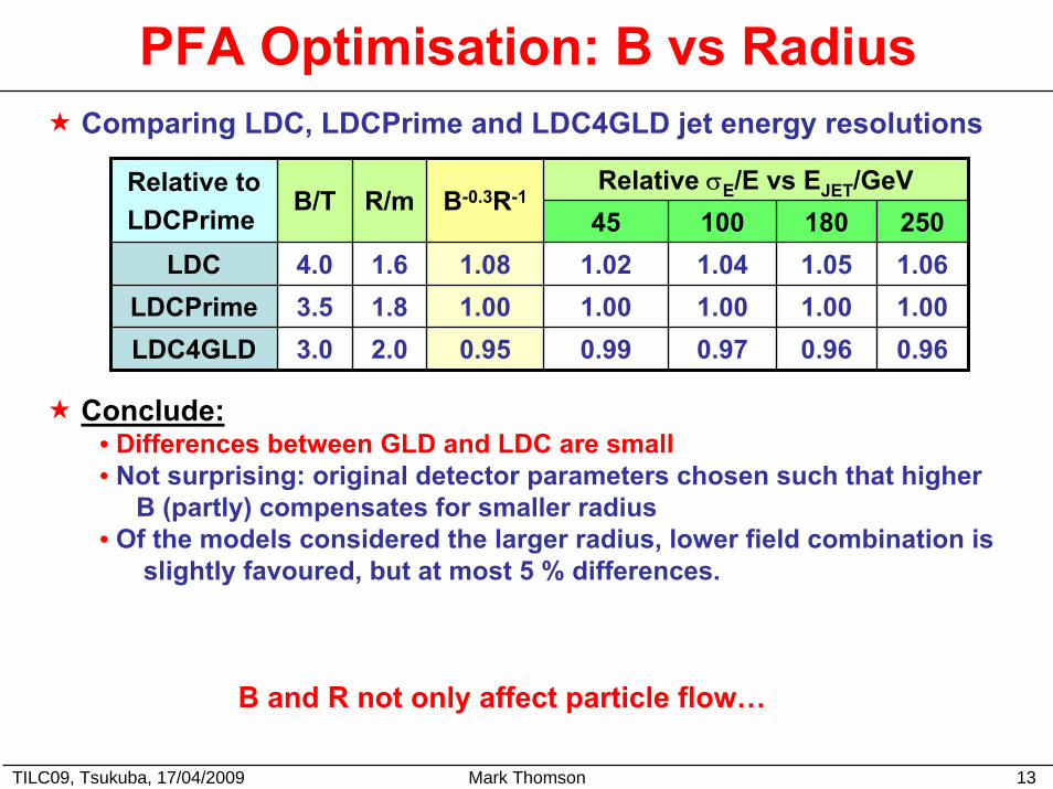
PFA Optimisation: B vs RadiusComparing LDC, LDCPrime and LDC4GLD jet energy resolutions
Relative σE/E vs EJET/GeVRelative toLDCPrime
B/T R/m
4.03.53.0
1.61.82.0
B-0.3R-145 100 180
1.08 1.021.000.99
1.001.051.04
1.00 1.000.97 0.960.95
250LDC 1.06
LDCPrime 1.00LDC4GLD 0.96
Conclude:• Differences between GLD and LDC are small• Not surprising: original detector parameters chosen such that higher
B (partly) compensates for smaller radius• Of the models considered the larger radius, lower field combination is
slightly favoured, but at most 5 % differences.
B and R not only affect particle flow…
TILC09, Tsukuba, 17/04/2009 Mark Thomson 14
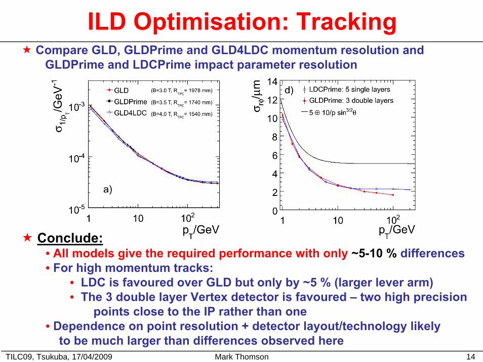
ILD Optimisation: TrackingCompare GLD, GLDPrime and GLD4LDC momentum resolution and
GLDPrime and LDCPrime impact parameter resolution
Conclude:• All models give the required performance with only ~5-10 % differences• For high momentum tracks:
• LDC is favoured over GLD but only by ~5 % (larger lever arm)• The 3 double layer Vertex detector is favoured – two high precision
points close to the IP rather than one• Dependence on point resolution + detector layout/technology likely
to be much larger than differences observed here
TILC09, Tsukuba, 17/04/2009 Mark Thomson 15
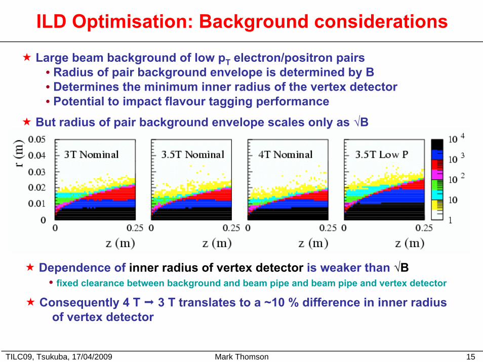
ILD Optimisation: Background considerations
Large beam background of low pT electron/positron pairs• Radius of pair background envelope is determined by B• Determines the minimum inner radius of the vertex detector• Potential to impact flavour tagging performance
But radius of pair background envelope scales only as √B
Dependence of inner radius of vertex detector is weaker than √B• fixed clearance between background and beam pipe and beam pipe and vertex detector
Consequently 4 T 3 T translates to a ~10 % difference in inner radiusof vertex detector
TILC09, Tsukuba, 17/04/2009 Mark Thomson 16
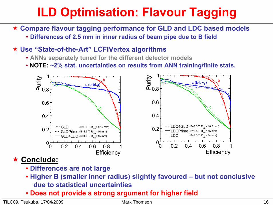
ILD Optimisation: Flavour TaggingCompare flavour tagging performance for GLD and LDC based models
• Differences of 2.5 mm in inner radius of beam pipe due to B field
Use “State-of-the-Art” LCFIVertex algorithms• ANNs separately tuned for the different detector models• NOTE: ~2% stat. uncertainties on results from ANN training/finite stats.
Conclude:• Differences are not large• Higher B (smaller inner radius) slightly favoured – but not conclusive
due to statistical uncertainties • Does not provide a strong argument for higher field
ILD Optimisation: Physics
TILC09, Tsukuba, 17/04/2009 Mark Thomson 17
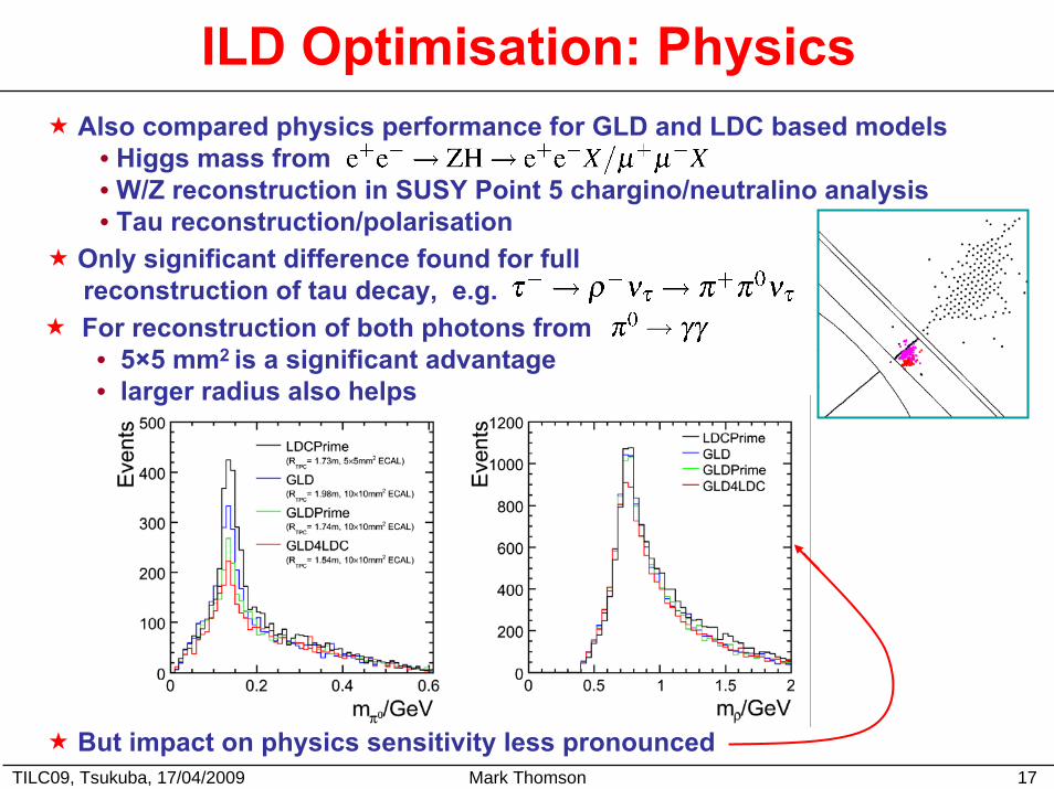
Also compared physics performance for GLD and LDC based models• Higgs mass from • W/Z reconstruction in SUSY Point 5 chargino/neutralino analysis• Tau reconstruction/polarisation
Only significant difference found for full reconstruction of tau decay, e.g.For reconstruction of both photons from
• 5×5 mm2 is a significant advantage• larger radius also helps
But impact on physics sensitivity less pronounced
TILC09, Tsukuba, 17/04/2009 Mark Thomson 18
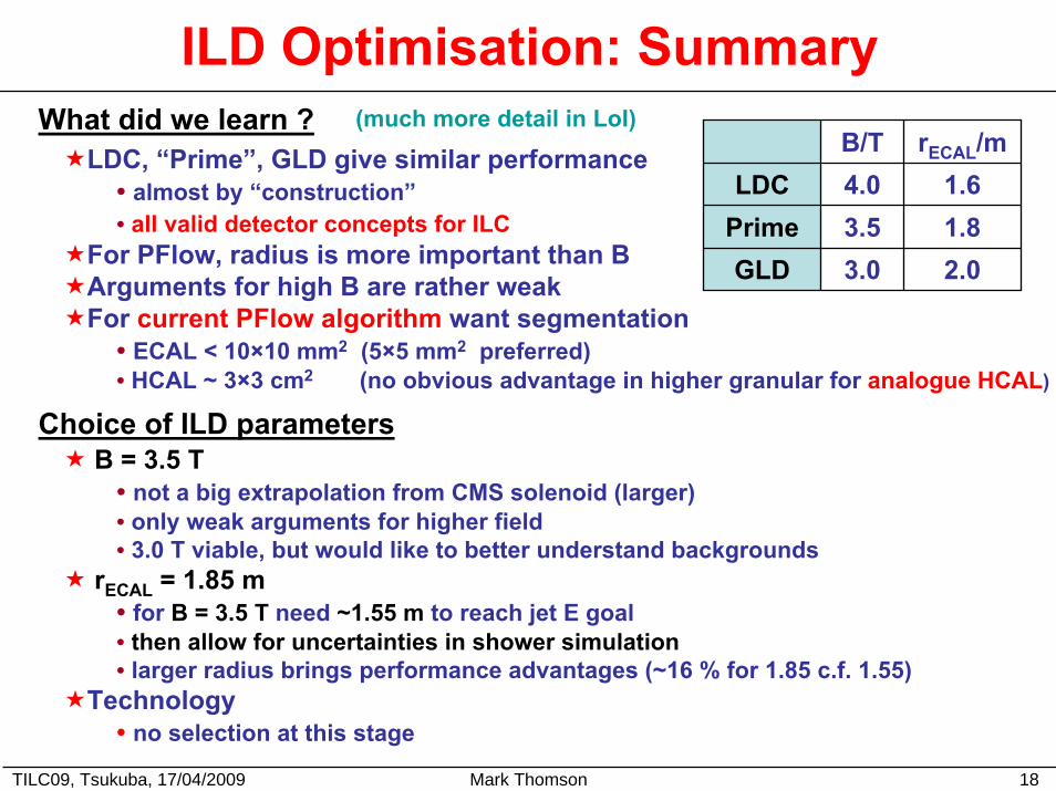
ILD Optimisation: SummaryWhat did we learn ? (much more detail in LoI)
LDC, “Prime”, GLD give similar performance• almost by “construction”• all valid detector concepts for ILC
For PFlow, radius is more important than BArguments for high B are rather weakFor current PFlow algorithm want segmentation
• ECAL < 10×10 mm2 (5×5 mm2 preferred)• HCAL ~ 3×3 cm2 (no obvious advantage in higher granular for analogue HCAL)
B/T rECAL/mLDC 4.0 1.6
Prime 3.5 1.8GLD 3.0 2.0
Choice of ILD parametersB = 3.5 T
• not a big extrapolation from CMS solenoid (larger)• only weak arguments for higher field• 3.0 T viable, but would like to better understand backgrounds
rECAL = 1.85 m• for B = 3.5 T need ~1.55 m to reach jet E goal • then allow for uncertainties in shower simulation • larger radius brings performance advantages (~16 % for 1.85 c.f. 1.55)
Technology • no selection at this stage
TILC09, Tsukuba, 17/04/2009 Mark Thomson 19
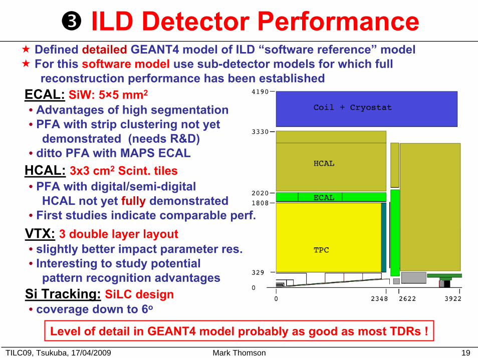
ILD Detector PerformanceDefined detailed GEANT4 model of ILD “software reference” modelFor this software model use sub-detector models for which full reconstruction performance has been established
ECAL: SiW: 5×5 mm2
• Advantages of high segmentation• PFA with strip clustering not yet
demonstrated (needs R&D)• ditto PFA with MAPS ECAL
HCAL: 3x3 cm2 Scint. tiles• PFA with digital/semi-digital
HCAL not yet fully demonstrated • First studies indicate comparable perf.
VTX: 3 double layer layout• slightly better impact parameter res.• Interesting to study potential
pattern recognition advantages Si Tracking: SiLC design• coverage down to 6o
Level of detail in GEANT4 model probably as good as most TDRs !
TILC09, Tsukuba, 17/04/2009 Mark Thomson 20
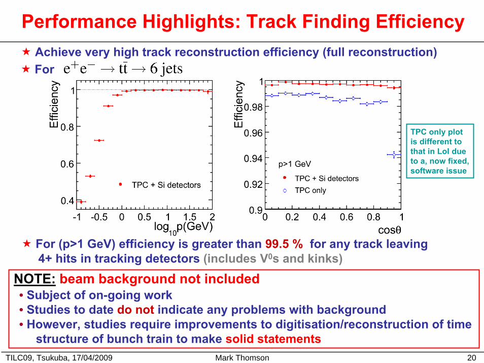
Performance Highlights: Track Finding Efficiency Achieve very high track reconstruction efficiency (full reconstruction)
TPC only plot is different to that in LoI due to a, now fixed,software issue
For
For (p>1 GeV) efficiency is greater than 99.5 % for any track leaving4+ hits in tracking detectors (includes V0s and kinks)
NOTE: beam background not included• Subject of on-going work• Studies to date do not indicate any problems with background• However, studies require improvements to digitisation/reconstruction of time
structure of bunch train to make solid statements
TILC09, Tsukuba, 17/04/2009 Mark Thomson 21
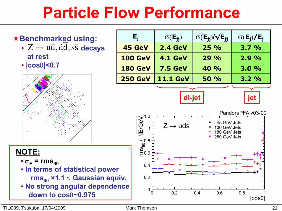
Particle Flow PerformanceEj σ(Ejj) σ(Ejj)/√Ejj σ(Ej)/Ej
45 GeV 2.4 GeV
4.1 GeV
7.5 GeV
11.1 GeV
25 % 3.7 %
100 GeV 29 % 2.9 %
180 GeV 40 % 3.0 %
250 GeV 50 % 3.2 %
Benchmarked using:• decays
at rest• |cosθ|<0.7
• σE = rms90• In terms of statistical power
rms90 ×1.1 ≈ Gaussian equiv.• No strong angular dependence
down to cosθ~0.975
NOTE:
di-jet jet
TILC09, Tsukuba, 17/04/2009 Mark Thomson 22
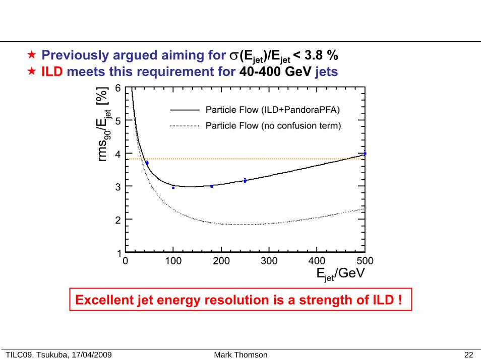
Previously argued aiming for σ(Ejet)/Ejet < 3.8 %ILD meets this requirement for 40-400 GeV jets
Excellent jet energy resolution is a strength of ILD !
TILC09, Tsukuba, 17/04/2009 Mark Thomson 23
ILD Physics Performance ILD Physics Studies:
Extensive set of analyses developed for LoI• “benchmark” and many other processes
All use full simulation/reconstructionLarge scale grid-based MC production ~30M events !Based on StdHep files generated at SLACTwo experienced reviewers assigned to each analysis
to give some level of feedback/quality assurance
Caveats:
A lot of impressive work from many people !
Different analyses have different levels of sophisticationNot the ultimate performance that can be achieved
• don’t draw too strong conclusions yet• except perhaps – that ILD is an excellent general purpose
detector for the ILC
Due to time constraints can only give “highlights” here…Significantly more in the LoI
: Higgs Recoil Mass
TILC09, Tsukuba, 17/04/2009 Mark Thomson 24
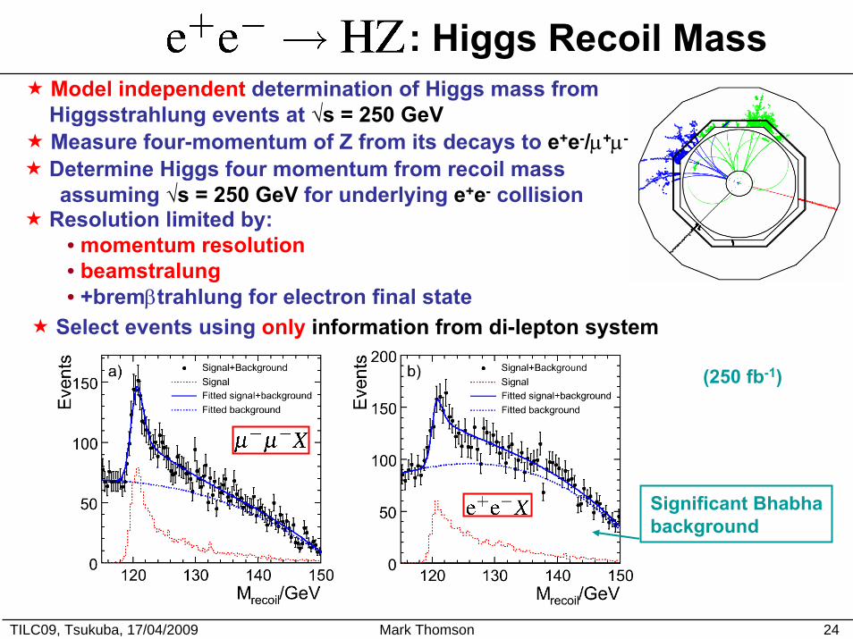
Model independent determination of Higgs mass fromHiggsstrahlung events at √s = 250 GeVMeasure four-momentum of Z from its decays to e+e-/µ+µ-
Determine Higgs four momentum from recoil mass assuming √s = 250 GeV for underlying e+e- collision
Resolution limited by: • momentum resolution• beamstralung• +bremβtrahlung for electron final state
Select events using only information from di-lepton system
(250 fb-1)
Significant Bhabhabackground
TILC09, Tsukuba, 17/04/2009 Mark Thomson 25
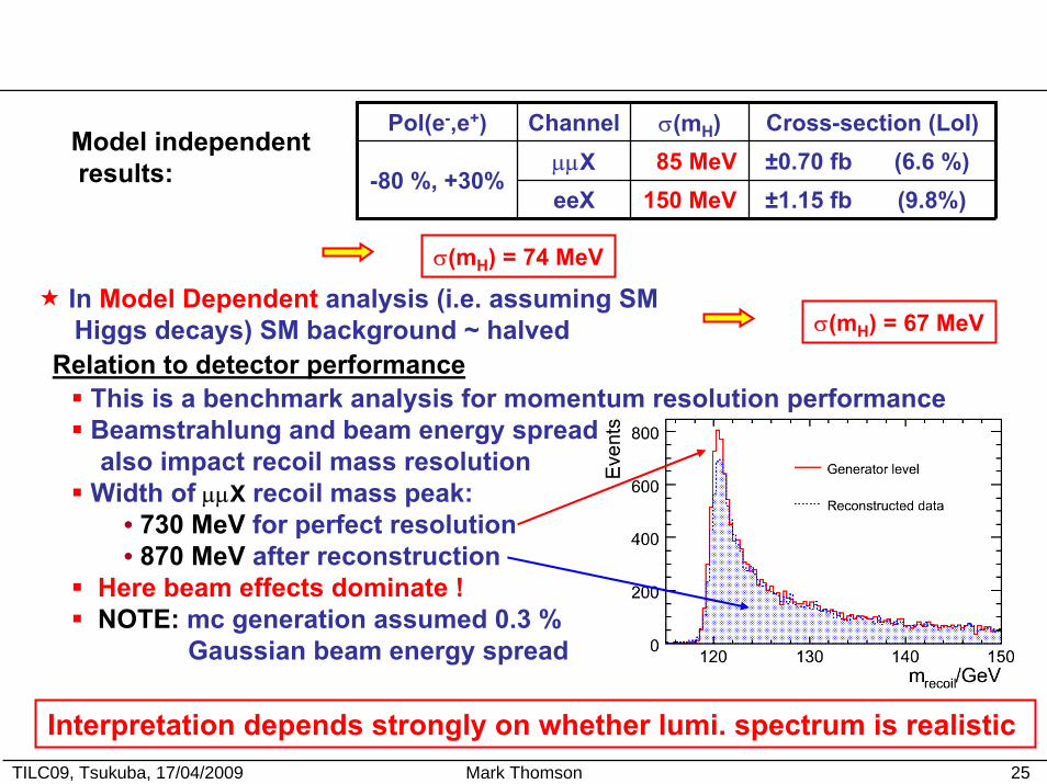
Pol(e-,e+) Channel σ(mH) Cross-section (LoI)µµX 85 MeV ±0.70 fb (6.6 %)eeX 150 MeV ±1.15 fb (9.8%)
-80 %, +30%Model independentresults:
σ(mH) = 74 MeV
σ(mH) = 67 MeV
Relation to detector performance
In Model Dependent analysis (i.e. assuming SM Higgs decays) SM background ~ halved
This is a benchmark analysis for momentum resolution performanceBeamstrahlung and beam energy spread also impact recoil mass resolution
Width of µµX recoil mass peak:• 730 MeV for perfect resolution• 870 MeV after reconstruction
Here beam effects dominate !NOTE: mc generation assumed 0.3 %
Gaussian beam energy spread
Interpretation depends strongly on whether lumi. spectrum is realistic
: Higgs Branching ratios
TILC09, Tsukuba, 17/04/2009 Mark Thomson 26
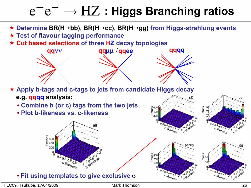
Determine BR(H bb), BR(H cc), BR(H gg) from Higgs-strahlung events Test of flavour tagging performanceCut based selections of three HZ decay topologies
qqνν qqµµ /qqee qqqq
Apply b-tags and c-tags to jets from candidate Higgs decaye.g. qqqq analysis:• Combine b (or c) tags from the two jets• Plot b-likeness vs. c-likeness
• Fit using templates to give exclusive σ
TILC09, Tsukuba, 17/04/2009 Mark Thomson 27
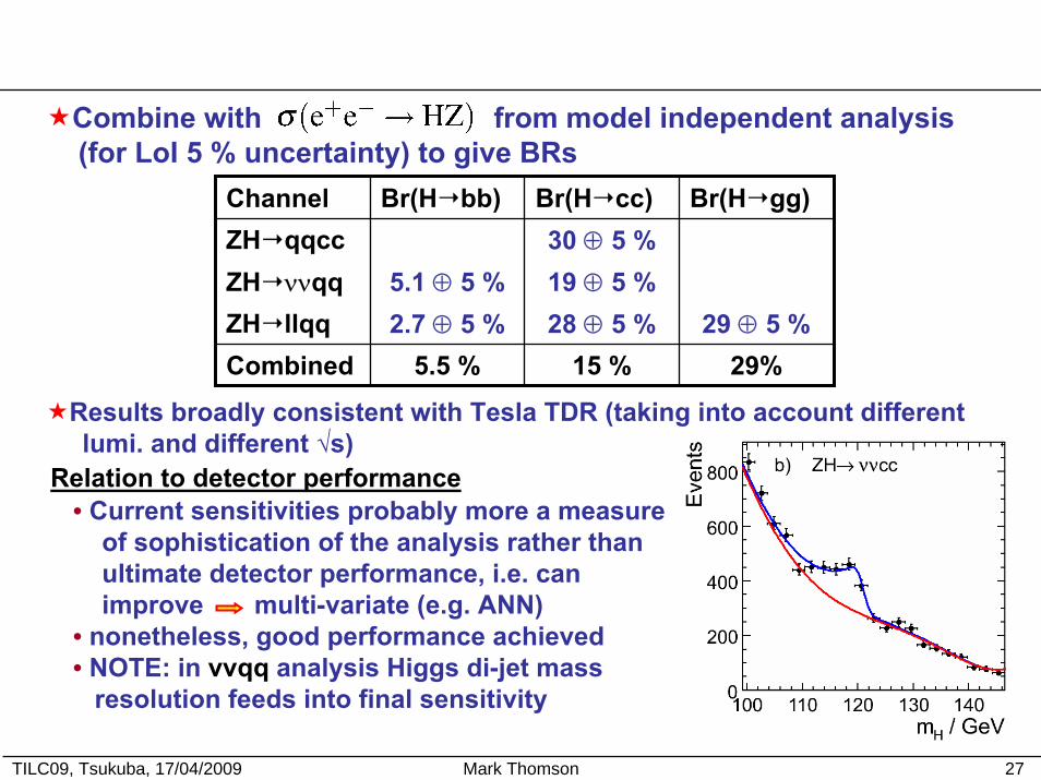
Combine with from model independent analysis(for LoI 5 % uncertainty) to give BRs
Channel Br(H bb) Br(H cc) Br(H gg)ZH qqcc 30 ⊕ 5 %ZH ννqq 5.1 ⊕ 5 % 19 ⊕ 5 % ZH llqq 2.7 ⊕ 5 % 28 ⊕ 5 % 29 ⊕ 5 %Combined 5.5 % 15 % 29%
Relation to detector performance
Results broadly consistent with Tesla TDR (taking into account different lumi. and different √s)
• Current sensitivities probably more a measure of sophistication of the analysis rather than ultimate detector performance, i.e. canimprove multi-variate (e.g. ANN)
• nonetheless, good performance achieved• NOTE: in vvqq analysis Higgs di-jet mass
resolution feeds into final sensitivity
TILC09, Tsukuba, 17/04/2009 Mark Thomson 28
Chargino and Neutralino Production at √s = 500 GeV
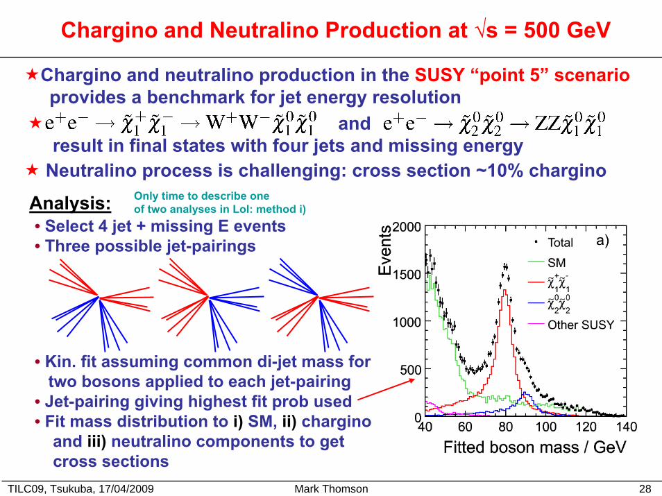
Chargino and neutralino production in the SUSY “point 5” scenarioprovides a benchmark for jet energy resolution
andresult in final states with four jets and missing energy
Neutralino process is challenging: cross section ~10% chargino
Analysis:• Select 4 jet + missing E events• Three possible jet-pairings
• Kin. fit assuming common di-jet mass for two bosons applied to each jet-pairing
• Jet-pairing giving highest fit prob used• Fit mass distribution to i) SM, ii) chargino
and iii) neutralino components to getcross sections
Only time to describe one of two analyses in LoI: method i)
TILC09, Tsukuba, 17/04/2009 Mark Thomson 29
Chargino and Neutralino Production at √s = 500 GeV
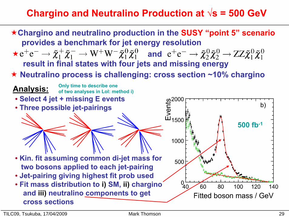
Chargino and neutralino production in the SUSY “point 5” scenarioprovides a benchmark for jet energy resolution
andresult in final states with four jets and missing energy
Neutralino process is challenging: cross section ~10% chargino
Analysis:• Select 4 jet + missing E events• Three possible jet-pairings
Only time to describe one of two analyses in LoI: method i)
• Kin. fit assuming common di-jet mass for two bosons applied to each jet-pairing
• Jet-pairing giving highest fit prob used• Fit mass distribution to i) SM, ii) chargino
and iii) neutralino components to getcross sections
500 fb-1
TILC09, Tsukuba, 17/04/2009 Mark Thomson 30
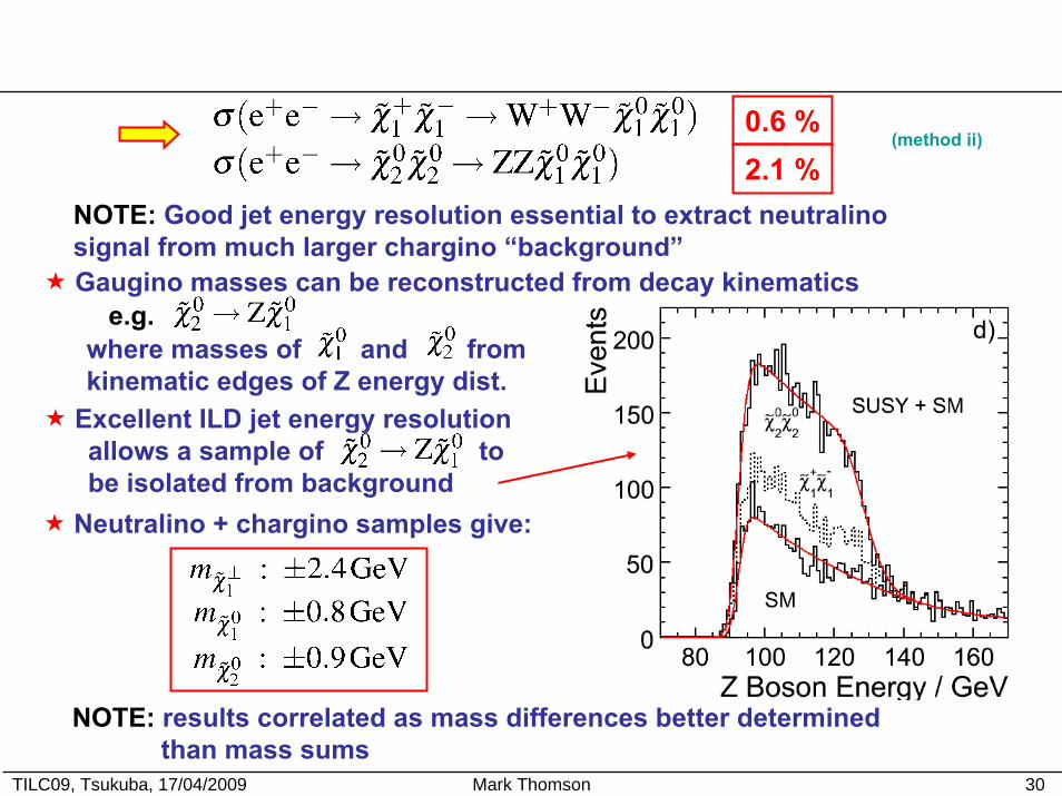
0.6 %(method ii)
2.1 %NOTE: Good jet energy resolution essential to extract neutralinosignal from much larger chargino “background”
e.g.Gaugino masses can be reconstructed from decay kinematics
where masses of and fromkinematic edges of Z energy dist.
Excellent ILD jet energy resolutionallows a sample of tobe isolated from background
Neutralino + chargino samples give:
NOTE: results correlated as mass differences better determined than mass sums
TILC09, Tsukuba, 17/04/2009 Mark Thomson 31
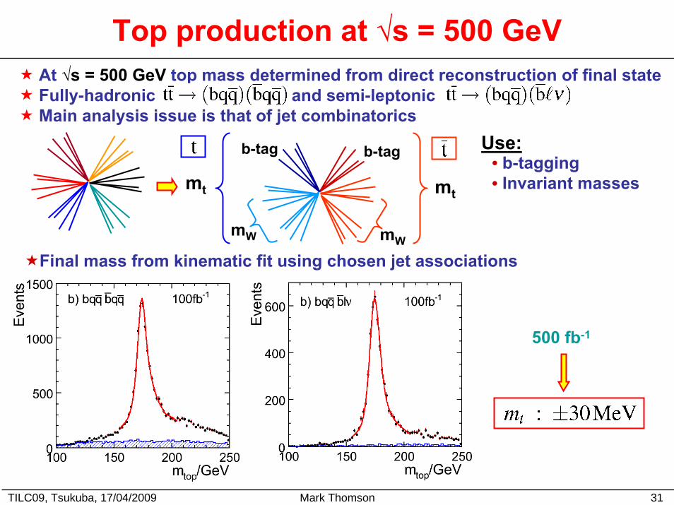
Top production at √s = 500 GeVAt √s = 500 GeV top mass determined from direct reconstruction of final stateFully-hadronic and semi-leptonicMain analysis issue is that of jet combinatorics
mW
b-tag
mt
mW
mt
b-tag Use:• b-tagging• Invariant masses
Final mass from kinematic fit using chosen jet associations
500 fb-1
TILC09, Tsukuba, 17/04/2009 Mark Thomson 32
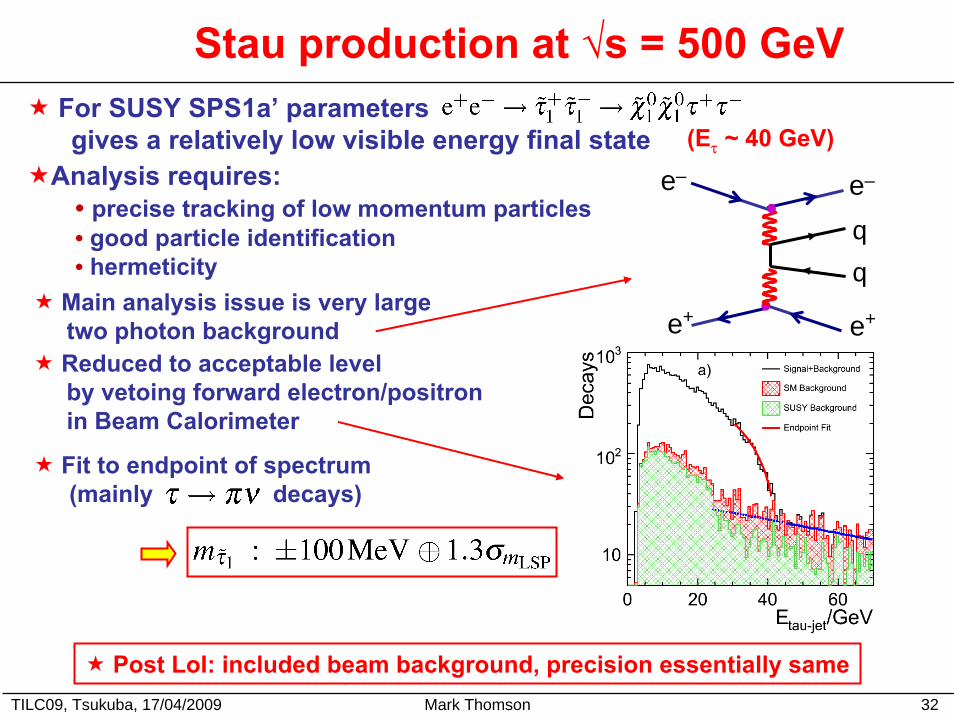
Stau production at √s = 500 GeVFor SUSY SPS1a’ parametersgives a relatively low visible energy final state (Eτ ~ 40 GeV)
Analysis requires:• precise tracking of low momentum particles• good particle identification• hermeticity
Main analysis issue is very large two photon backgroundReduced to acceptable levelby vetoing forward electron/positron in Beam Calorimeter
e+e+
e–e–
Fit to endpoint of spectrum(mainly decays)
Post LoI: included beam background, precision essentially same
TILC09, Tsukuba, 17/04/2009 Mark Thomson 33
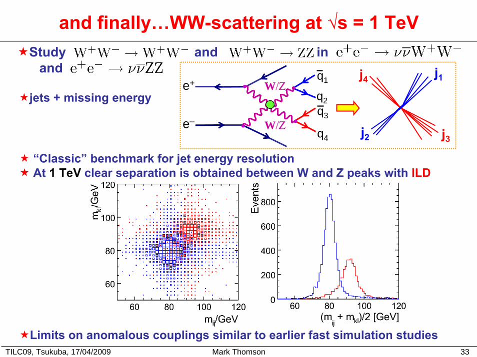
and finally…WW-scattering at √s = 1 TeV
j1
j2 j3
j4
e–
e+ W/Ζ
W/Ζ
q2q3
q4
q1
Study and in and
jets + missing energy
“Classic” benchmark for jet energy resolutionAt 1 TeV clear separation is obtained between W and Z peaks with ILD
Limits on anomalous couplings similar to earlier fast simulation studies
TILC09, Tsukuba, 17/04/2009 Mark Thomson 34
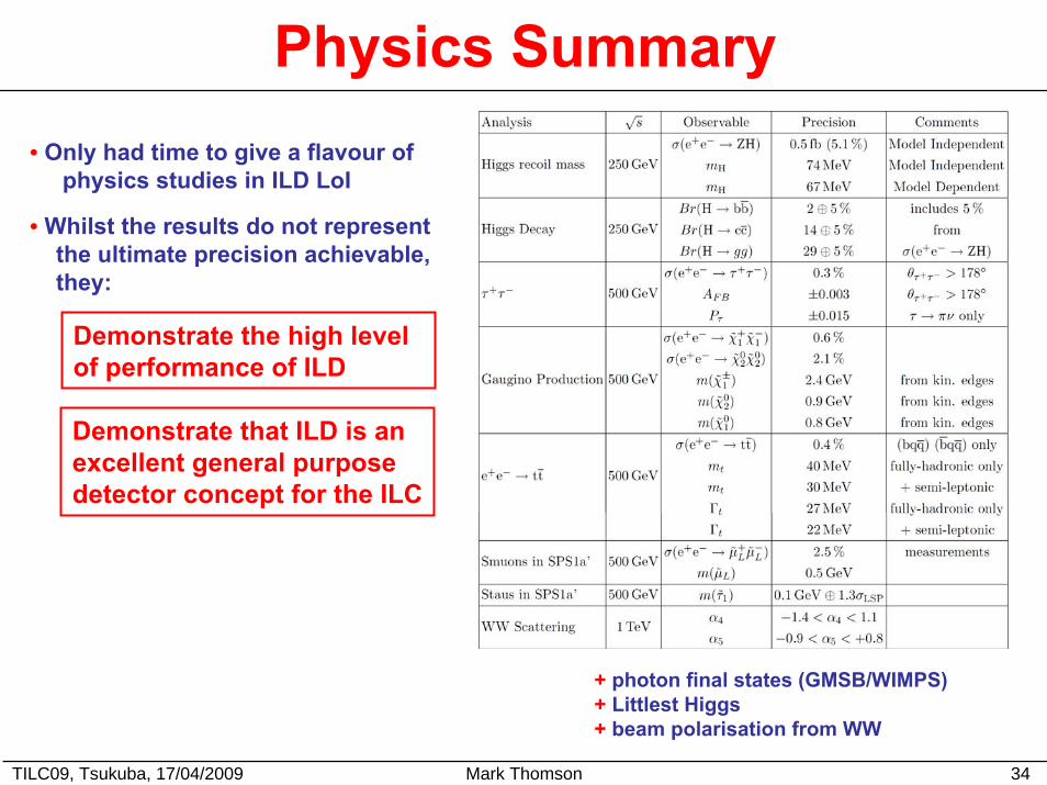
Physics Summary• Only had time to give a flavour of
physics studies in ILD LoI
• Whilst the results do not representthe ultimate precision achievable,they:
Demonstrate the high level of performance of ILD
Demonstrate that ILD is an excellent general purposedetector concept for the ILC
+ photon final states (GMSB/WIMPS)+ Littlest Higgs + beam polarisation from WW
TILC09, Tsukuba, 17/04/2009 Mark Thomson 35
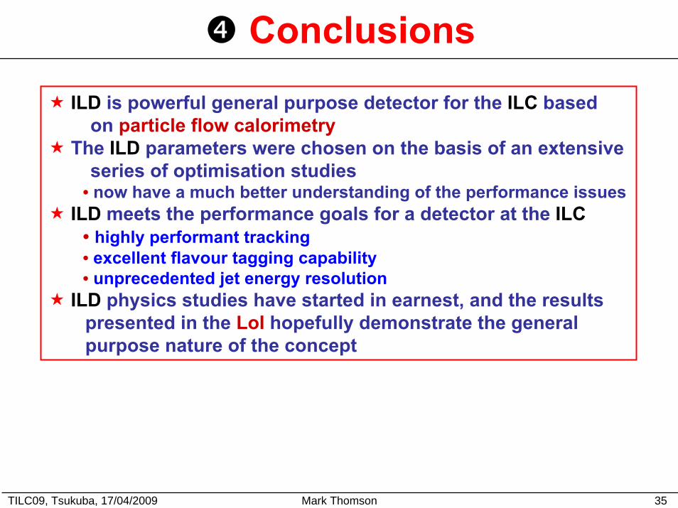
Conclusions
ILD is powerful general purpose detector for the ILC based on particle flow calorimetry
The ILD parameters were chosen on the basis of an extensive series of optimisation studies
• now have a much better understanding of the performance issuesILD meets the performance goals for a detector at the ILC
• highly performant tracking• excellent flavour tagging capability• unprecedented jet energy resolution
ILD physics studies have started in earnest, and the results presented in the LoI hopefully demonstrate the generalpurpose nature of the concept

TILC09, Tsukuba, 17/04/2009 Mark Thomson 36
Over to Sugimoto-san…
TILC09, Tsukuba, 17/04/2009 Mark Thomson 37
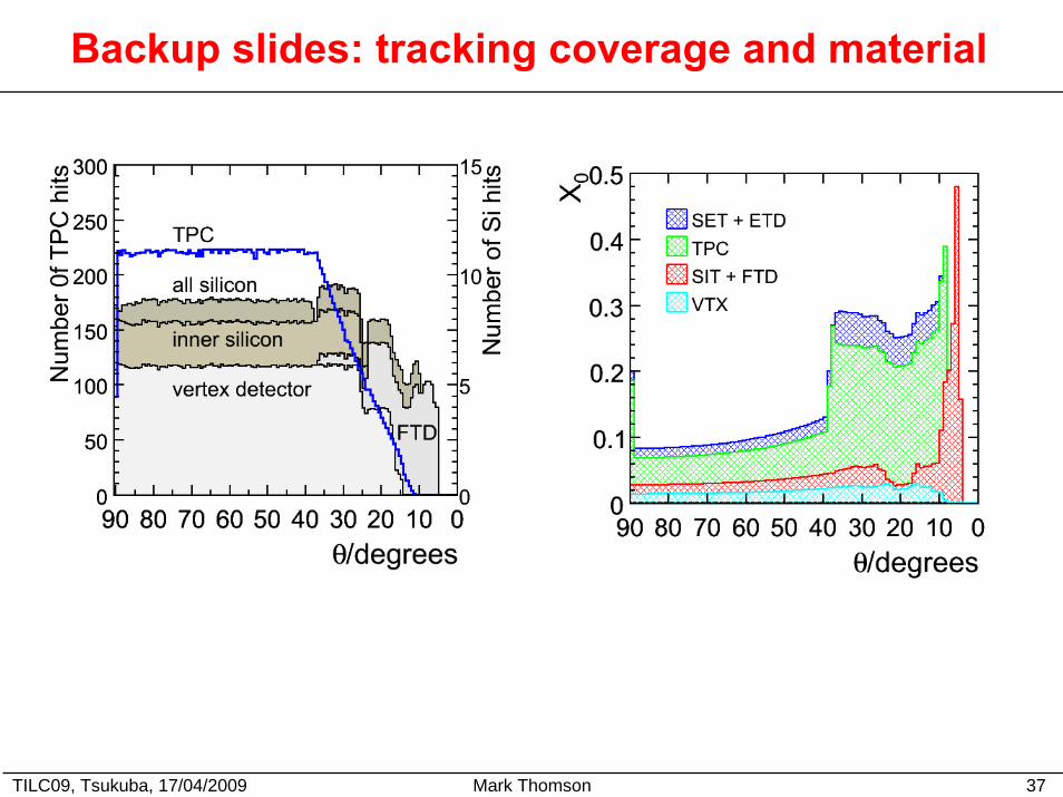
Backup slides: tracking coverage and material
TILC09, Tsukuba, 17/04/2009 Mark Thomson 38
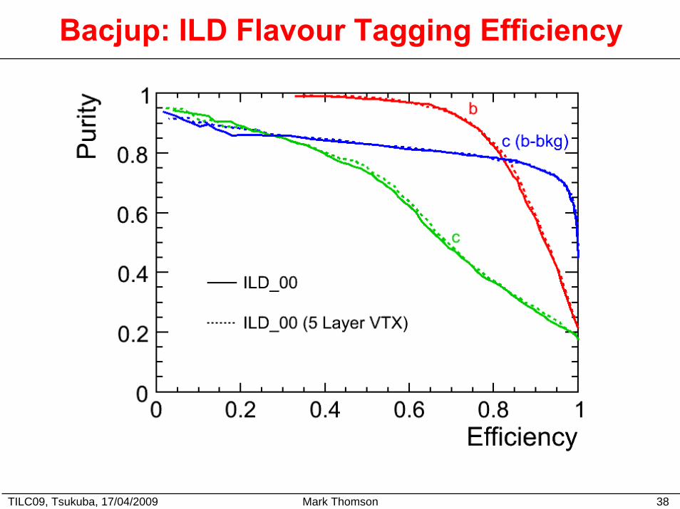
Bacjup: ILD Flavour Tagging Efficiency
TILC09, Tsukuba, 17/04/2009 Mark Thomson 39
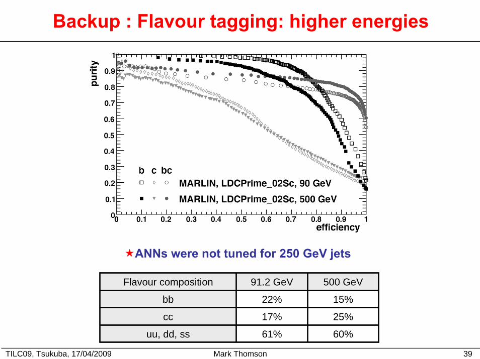
Backup : Flavour tagging: higher energies
ANNs were not tuned for 250 GeV jets
Flavour composition 91.2 GeV 500 GeV
bb 22% 15%
cc 17% 25%
uu, dd, ss 61% 60%
TILC09, Tsukuba, 17/04/2009 Mark Thomson 40
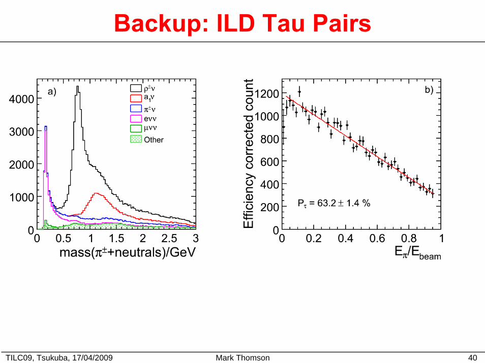
Backup: ILD Tau Pairs