Embed Size (px)
Citation preview
ILD Large Prototype TPC tests with Micromegas
D. Attié, A. Bellerive, P. Colas, E. Delagnes, M. Dixit, I. Giamatoris, A. Giganon J.-P. Martin, M. Riallot, F. Senée, N. Shiell, Y-H Shin, S. Turnbull, R. Yonamine, M. Vujicic
(Saclay, Carleton, Montreal, TRIUMF, KEK)
GEM & Micromegas options for ILC TPC
Micromegas panels for Large Prototype
Studies on resistive coatings
Installation at DESY
Software and simulation
Status of beam tests
LCWS 2008 Chicago 2
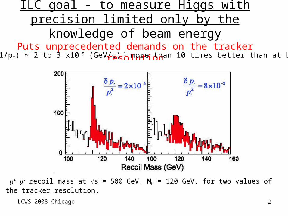
ILC goal - to measure Higgs with precision limited only by the knowledge of beam energy
Puts unprecedented demands on the tracker resolution∆(1/pT) ~ 2 to 3 x10⁻⁵ (GeV/c)-1 more than 10 times better than at LEP!
recoil mass at s = 500 GeV. MH = 120 GeV, for two values of the tracker resolution.

LCWS 2008 Chicago 3
TPC development for the ILD central tracker
TPC an ideal central tracker for physics at ILC•Low mass, minimal photon conversion•High efficiency, high granularity continuous tracking, •Excellent pattern recognition, •Particle ID •∆(1/pT) ~ 1 x 10⁻⁴ (GeV-1) (TPC alone) ~ 3.10-5 (GeV-1) (vertex + Si inner tracker + TPC)
TPC parameters: •200 track points• (r, ) 100 m includes stiff 90 tracks ~ 2 m drift (z) ~ 1 mm 2 track(r, ) ~ 2 mm2 track(z) ~ 5 mm •dE/dx ~ 5%

LCWS 2008 Chicago 4
Limits on achievable TPC resolution•The physics limit of TPC resolution comes from transverse diffusion:
Neff = effective electron statistics.
•For best resolution, choose a gas with smallest diffusion in a high B field
€
x2 ≈DTr
2 ⋅zNeff
For small diffusion, less precise centroid for wide pads
Micro PatternGas Detector
Proportional wire
Anode pads
Cathode pads
Induced cathode signal determined by geometry
Direct signal on MPGD anode pads
width w width w
Accurate centroid determination possible with wide pads
eff
Trx N
zD ⋅+≈
22
02 [ ]12
1 2220
2 wzDN Treff
x ++≈ σσ
Pad width limits the MPGD TPC resolution
ExB systematics limits wire/pad TPC resolution

LCWS 2008 Chicago 5
Micro-Pattern Gas Detector R&D for ILD TPC
•2 mm x 6 mm pads (1,500,000 channels) with GEMs or Micromegas proposed initially (TESLA TDR)•For the GEM, large transverse diffusion in the transfer & induction gaps provides a natural mechanism to disperse the charge improving centroid determination with wide pads. •LC TPC R&D: 2 mm pads too wide with conventional readout. The GEM TPC readout will need ~ 1 mm wide pads to achieve the 100 m ILC resolution goal (~3,000,000 channels) •Even narrower pads needed for the MicromegasCharge dispersion - a mechanism to disperse the MPGD avalanche charge so that wide pads can be used for centroid determination.
LCWS 2008 Chicago 6
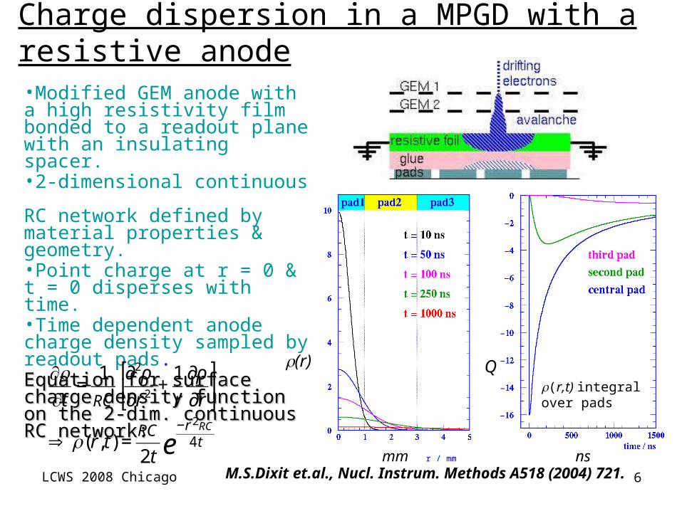
•Modified GEM anode with a high resistivity film bonded to a readout plane with an insulating spacer.•2-dimensional continuous RC network defined by material properties & geometry.•Point charge at r = 0 & t = 0 disperses with time.•Time dependent anode charge density sampled by readout pads.Equation for surface charge Equation for surface charge density function on the 2-dim. density function on the 2-dim. continuous RC network:continuous RC network:
€
∂ρ∂t
=1
RC
∂2ρ
∂r2+
1
r
∂ρ
∂r
⎡
⎣ ⎢
⎤
⎦ ⎥
€
⇒ ρ(r, t) =RC
2t
−r2RC
4 te
ρ(r,t) integral over pads
ρ(r) Q
r / mmmm ns
Charge dispersion in a MPGD with a resistive anode
M.S.Dixit et.al., Nucl. Instrum. Methods A518 (2004) 721.

LCWS 2008 Chicago 7
Cosmic ray tests at DESY in a 5 Tesla magnet Micromegas TPC with charge dispersion readout
~ 50 m av. resolution over 15 cm (diffusion negligible)100 m over 2 meters looks within reach!
Nov-Dec, 2006
DTr= 19 m/cm, 2 x 6 mm2 pads
M. Dixit et. al, NIM A 581, 254 (2007)

LCWS 2008 Chicago 8
TPC Large Prototype (LP) Beam Test at DESYby LC TPC Collaboration using EUDET Facility
GoalsGoals
Study, in practice, design and fabrication of Study, in practice, design and fabrication of all components of MPGD TPC in larger scale; all components of MPGD TPC in larger scale; field cage, field cage, endplate, detector modules, endplate, detector modules, front-end electronics and field mapping of front-end electronics and field mapping of non uniform magnetic field. (But not yet the non uniform magnetic field. (But not yet the engineering stage.)engineering stage.)
Demonstrate full-volume tracking in non-Demonstrate full-volume tracking in non-uniform magnetic field, trying to provide a uniform magnetic field, trying to provide a proof for the momentum resolution at LC proof for the momentum resolution at LC TPC.TPC.
Demonstrate dE/dX capability of MPGD TPC. Demonstrate dE/dX capability of MPGD TPC. Study effects of detector boundaries. Study effects of detector boundaries.
Develop methods and software for Develop methods and software for alignment, calibration, and corrections.alignment, calibration, and corrections.
(Beijing tracker review, Jan 2007)(Beijing tracker review, Jan 2007)
Beam
From Takeshi MATSUDA - 2From Takeshi MATSUDA - 2ndnd RD51 Collaboration Meeting Paris 13 Oct, RD51 Collaboration Meeting Paris 13 Oct, 20082008

LCWS 2008 Chicago 9
GEMs & Micromegas both being developed presently GEMs readout with ~ 1 mm wide padsGEMs readout with ~ 1 mm wide padsMicromegas with 2-3 mm wide pads charge dispersion Micromegas with 2-3 mm wide pads charge dispersion readoutreadout

Micromegas panel designed & fabricated at Saclay
LCWS 2008 Chicago 11
•Point to point variations of surface resistivity (R) and capacitance density (C) of anode pad readout structure must be minimized •Non-uniform RC response leads to systematic bias in position determination•Bias easy to correct for small 10 cm x 10 cm Micromegas tested so far •Development of Bulk Micromegas with resistive anode readout•AFTER front-end based on T2K readout electronics
R&D specific to LP Micromegas panelsR&D specific to LP Micromegas panels
LCWS 2008 Chicago 12
xtrack / mm (± 14 mm)
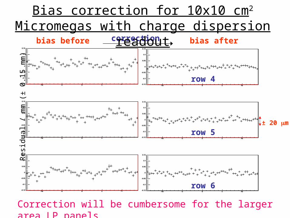
± 20 m
Res
idua
l / m
m (
± 0.
15 m
m)
bias before bias aftercorrection
row 4
row 5
row 6
Bias correction for 10x10 cm2 Micromegas with charge dispersion readout
Correction will be cumbersome for the larger area LP panels

LCWS 2008 Chicago 13
Development of uniform high surface resistivity anode films
Several techniques are being tested for the resistive anode coating
1) Carbon-loaded Kapton. An old technique first tested at Carleton applied to bulk Micromegas with improvement in laminating resistive film to pad readout PCB
First results promising. One panel produced.
LCWS 2008 Chicago 14
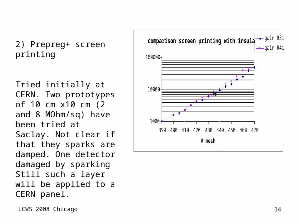
2) Prepreg+ screen printing
Tried initially at CERN. Two prototypes of 10 cm x10 cm (2 and 8 MOhm/sq) have been tried at Saclay. Not clear if that they sparks are damped. One detector damaged by sparking Still such a layer will be applied to a CERN panel.
comparison screen printing with insulator
1000
10000
100000
390 400 410 420 430 440 450 460 470
V mesh
gain
gain R3i
gain R4i
tin

LCWS 2008 Chicago 15
The panelsPCBs have been produced
4 with the Saclay routing in 6 layers
4 with the CERN routing with 4 layers
LCWS 2008 Chicago 16
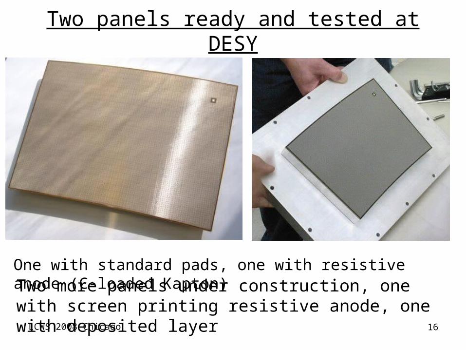
Two panels ready and tested at DESY
One with standard pads, one with resistive anode (C-loaded Kapton)Two more panels under construction, one with screen printing resistive anode, one with deposited layer
LCWS 2008 Chicago 17
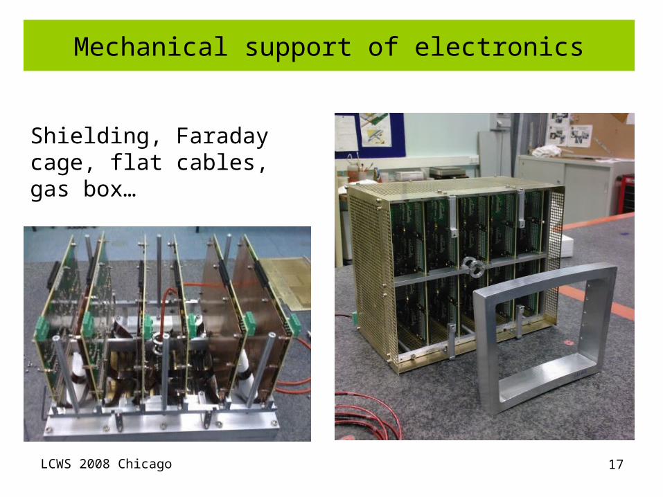
Mechanical support of electronics
Shielding, Faraday cage, flat cables, gas box…
LCWS 2008 Chicago 18
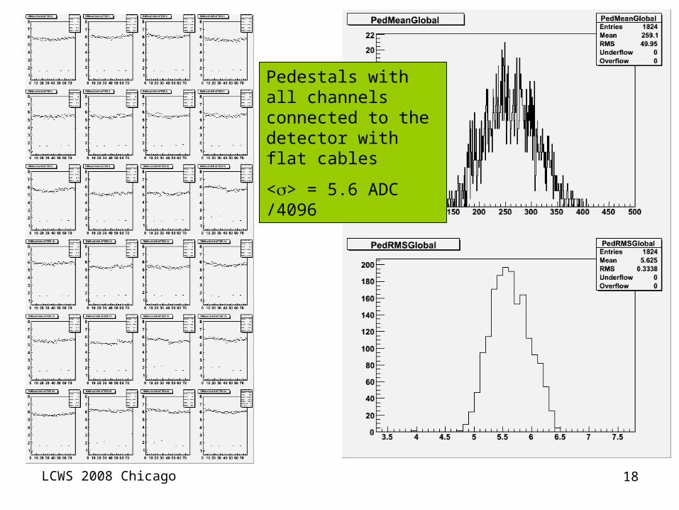
Pedestals with all channels connected to the detector with flat cables
<> = 5.6 ADC /4096
LCWS 2008 Chicago 19
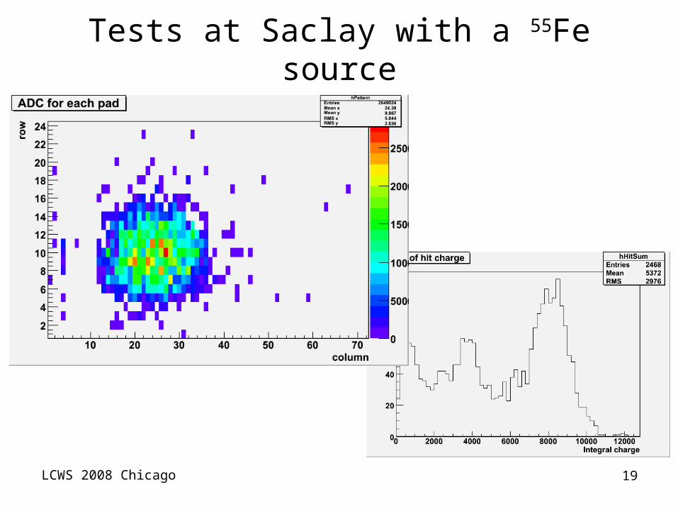
Tests at Saclay with a 55Fe source
LCWS 2008 Chicago 20
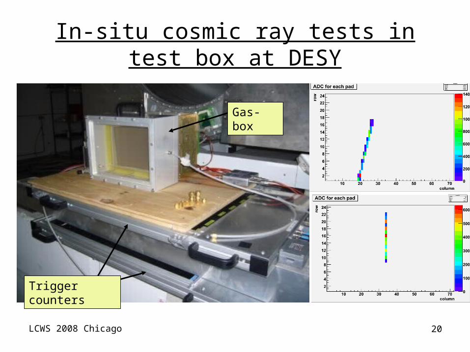
In-situ cosmic ray tests in test box at DESY
Gas-box
Trigger counters
LCWS 2008 Chicago 21
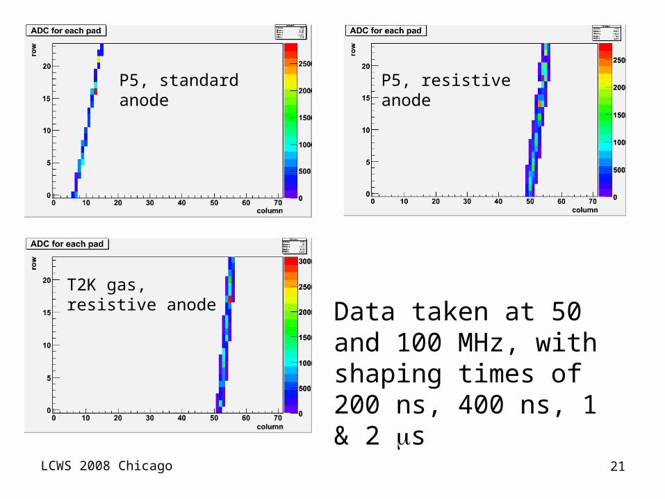
P5, standard anode P5, resistive anode
T2K gas, resistive anode Data taken at 50 and 100
MHz, with shaping times of 200 ns, 400 ns, 1 & 2 s

LCWS 2008 Chicago 22
Presently developing software and analysis tools (D. Attié, S. Turnbull, Yun-Ha Shin, with Martin Killenberg): LCIO converter, JTPC, Marlin
Event display

LCWS 2008 Chicago 23
AFTER electronics installation
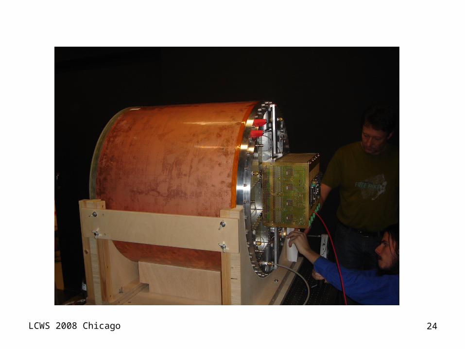
LCWS 2008 Chicago 24
LCWS 2008 Chicago 25
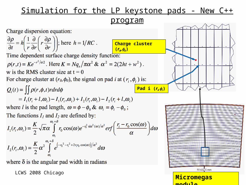
Simulation for the LP keystone pads - New C++ program
i
Micromegas module
Charge cluster (r0,0)
Pad i (ri,i)

LCWS 2008 Chicago 26
High momentum simulated track signal B = 4 T (keystone pads)
Pad dimensionsLength = 6 mmWidth 1.984 mrad
Micromegas risetime 50 ns, preamp rise time 40 ns, preamp decay time 2 s, Anode resistivity 1 M/, Dielectric gap = 75 m, dielectric constant 1.85
Ar/CF4/C4H10 95/3/2, E = 200 V/cm, vdrift = 73 m/ns DT = 23 m/cm DL =249 m/cm
LCWS 2008 Chicago 27
Present status and plans
TPC field cage tested to 19 kV in air and is presently being flushed with gasMagnet is readyMove TPC to beam area Initial data taking with standard readout
Cosmic raysWith beam With beam and magnetSwitch to resistive anode readout

LCWS 2008 Chicago 28
Future plans
Start R&D for electronics on a mezzanine PCB. Planned for early 2010.
- R&D to optimize protection, compactness
- Development to test AFTER chips at the wafer level
- new card design
Make 7 fully equipped modules
Start cooling and integration studies