Embed Size (px)
Citation preview
IK1ZYWFrequency Reader
for FT-817(ND)(and FT-857/FT-897)
User's Manual
(for transverter users)
An IK1ZYW creation.All rights reserved.
IK1ZYW Frequency Reader for FT-817 (transverter)
Table of ContentsWhat is it?.............................................................................................................................................3Special thanks.......................................................................................................................................4Disclaimer.............................................................................................................................................5Quick start............................................................................................................................................6Tested on...............................................................................................................................................7How it works........................................................................................................................................8
Normal mode...................................................................................................................................8Config mode....................................................................................................................................9
Difference mode........................................................................................................................10Customizing........................................................................................................................................12Support...............................................................................................................................................13Technical specifications......................................................................................................................14Troubleshooting..................................................................................................................................15Microcontroller choice.......................................................................................................................16Microcontroller programming............................................................................................................17Assembling.........................................................................................................................................18
Warnings........................................................................................................................................19Connections........................................................................................................................................20
To LCD..........................................................................................................................................20To FT-817.......................................................................................................................................20
For FT-857/FT-897 Owners................................................................................................................21
Doc. v.20110313 2
IK1ZYW Frequency Reader for FT-817 (transverter)
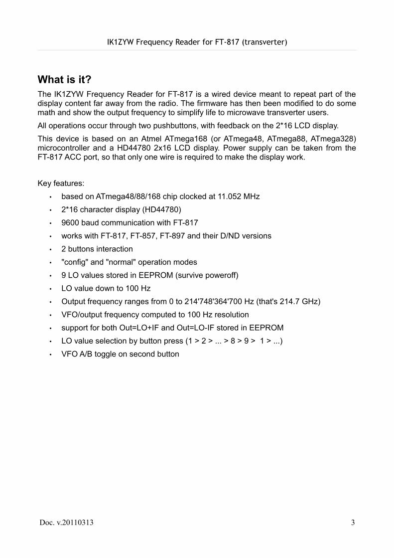
What is it?The IK1ZYW Frequency Reader for FT-817 is a wired device meant to repeat part of the display content far away from the radio. The firmware has then been modified to do some math and show the output frequency to simplify life to microwave transverter users.All operations occur through two pushbuttons, with feedback on the 2*16 LCD display.This device is based on an Atmel ATmega168 (or ATmega48, ATmega88, ATmega328) microcontroller and a HD44780 2x16 LCD display. Power supply can be taken from the FT-817 ACC port, so that only one wire is required to make the display work.
Key features:• based on ATmega48/88/168 chip clocked at 11.052 MHz• 2*16 character display (HD44780)• 9600 baud communication with FT-817• works with FT-817, FT-857, FT-897 and their D/ND versions• 2 buttons interaction• "config" and "normal" operation modes• 9 LO values stored in EEPROM (survive poweroff)• LO value down to 100 Hz• Output frequency ranges from 0 to 214'748'364'700 Hz (that's 214.7 GHz)• VFO/output frequency computed to 100 Hz resolution• support for both Out=LO+IF and Out=LO-IF stored in EEPROM• LO value selection by button press (1 > 2 > ... > 8 > 9 > 1 > ...)• VFO A/B toggle on second button
Doc. v.20110313 3
IK1ZYW Frequency Reader for FT-817 (transverter)
Special thanksThis project has been made possible thanks to, in chronological order:
● my Parents that bought me an experimenter's book when I was 10 and supported me in my studies, hobbies and choices
● my high school electronics Teachers Bruno De Stefano and Elisabetta Cuniberti, whose passion for the subject has furthermore marked my life
● KA7OEI that published an extensive guide to Yaesu's CAT protocol● my supporting Wife and curious Daughters that let me dedicate some night time to
this idea, and patiently tolerated the kitchen table invasion
Doc. v.20110313 4
IK1ZYW Frequency Reader for FT-817 (transverter)
Disclaimer
Important notice, read twice. Although the Frequency Reader firmware is not sending dangerous data to the radio, the communication protocol does not use any form of checksum. Therefore a mis-interpretation by the radio can cause unexpected results, from a CPU crash (needing a power off-on cycle) to a complete wipe of all EEPROM data, including configuration, software calibration/alignment1 and memories. You are strongly encouraged to record at least all 76 “soft calibration” settings, plus any other information stored in your radio before using this circuit 2 .The 13.8Vcc line on the ACC port of FT-817 is connected to the power supply through a 10 ohm 1/16W resistor. It is not fused. Damage to the radio will occur if this line gets shorted. Moreover the voltage on ACC port is always present, including when internal batteries are installed and the radio powered off: don't forget to switch off your Frequency Reader, or unplug it when not in use! If you feel uncomfortable in using this line please use a separate 9V battery to power the Frequency Reader. Otherwise use heatshrink pipes for each pin on homemade plugs.No responsibility is taken for data loss or any damage to your equipment.
All trademarks belong to respective owners (Yaesu, Atmel, Icom, Microchip,...).
1 Software calibration settings are unique to every single device. If their values get lost you need to send your radio back to Yaesu for re-alignment. These settings are accessed by pressing keys A+B+C simultaneously and then powering up the radio. Copy them all to paper and store it in a safe place. Feel free to make several copies of your backup.
2 This safery procedure should be undertaken even when using a CAT computer cable and a computer control software. The danger is not in this circuit but in the potential misinterpretation of data by the FT817.
Doc. v.20110313 5
IK1ZYW Frequency Reader for FT-817 (transverter)
Quick startWhile it is worth reading this document to the end, I understand you might want to start using your Frequency Reader as soon as possible. Follow the following steps in order to get started.Steps 1 to 4 can be done before your Frequency Reader is built or in your possession.
1. Do NOT connect the Frequency Reader to the radio, YET2. Turn on your FT-817, long press the [F] button, navigate to “14 CAT RATE” using
the [SEL] rotary switch and set it to 9600 baud. Long press [F] again to store this setting.
3. Turn off the transceiver4. (Optional but strongly recommended) Record the soft calibration settings that are
exclusive for your piece of equipment. Keep [A] [B] and [C] buttons pressed while turning on the FT-817. Browse through all setting using [SEL] rotary switch and record on paper their value. Make copies of the paper and put them in the safe. Turn off the FT-817 as usual.
5. Remove ALL power sources including the internal battery, if your circuit does not carry an on/off switch
6. Connect the display cable to the rear ACC socket. Be gentle and patient, do not force it
7. Looking at the Frequency Reader LCD, apply power to the radio and display circuit (ie switch on the power supply and the on/off switch if installed): the LCD should show a row full of “###”, the display welcome message and, in a couple of seconds, a “Comm Error” because the radio is off
8. Switch on your FT-817 and wait about 5 seconds9. The Frequency Reader enters “normal” operation mode, showing the sum of VFO +
LO#1 (10'224'000'000 Hz)10.Enjoy
Doc. v.20110313 6
IK1ZYW Frequency Reader for FT-817 (transverter)
Tested on...This circuit has been developed on a FT817ND/I (Italian version) with serial number 5H00xxxx. The Frequency Reader firmware uses only CAT commands from the User's Manual.Since the CAT protocol is the same for FT-817, FT-857 and FT-897, the Frequency Reader should work on all three models.
Doc. v.20110313 7
IK1ZYW Frequency Reader for FT-817 (transverter)
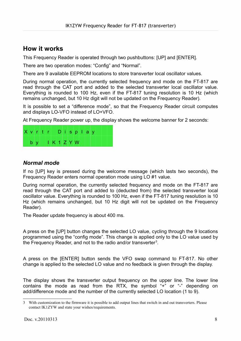
How it worksThis Frequency Reader is operated through two pushbuttons: [UP] and [ENTER].There are two operation modes: “Config” and “Normal”.There are 9 available EEPROM locations to store transverter local oscillator values.During normal operation, the currently selected frequency and mode on the FT-817 are read through the CAT port and added to the selected transverter local oscillator value. Everything is rounded to 100 Hz, even if the FT-817 tuning resolution is 10 Hz (which remains unchanged, but 10 Hz digit will not be updated on the Frequency Reader).It is possible to set a “difference mode”, so that the Frequency Reader circuit computes and displays LO-VFO instead of LO+VFO.At Frequency Reader power up, the display shows the welcome banner for 2 seconds:
X v r t r D i s p l a y
b y I K 1 Z Y W
Normal modeIf no [UP] key is pressed during the welcome message (which lasts two seconds), the Frequency Reader enters normal operation mode using LO #1 value.During normal operation, the currently selected frequency and mode on the FT-817 are read through the CAT port and added to (deducted from) the selected transverter local oscillator value. Everything is rounded to 100 Hz, even if the FT-817 tuning resolution is 10 Hz (which remains unchanged, but 10 Hz digit will not be updated on the Frequency Reader).The Reader update frequency is about 400 ms.
A press on the [UP] button changes the selected LO value, cycling through the 9 locations programmed using the “config mode”. This change is applied only to the LO value used by the Frequency Reader, and not to the radio and/or transverter3.
A press on the [ENTER] button sends the VFO swap command to FT-817. No other change is applied to the selected LO value and no feedback is given through the display.
The display shows the transverter output frequency on the upper line. The lower line contains the mode as read from the RTX, the symbol “+” or “-” depending on add/difference mode and the number of the currently selected LO location (1 to 9).
3 With customization to the firmware it is possible to add output lines that switch in and out transverters. Please contact IK1ZYW and state your wishes/requirements.
Doc. v.20110313 8
IK1ZYW Frequency Reader for FT-817 (transverter)
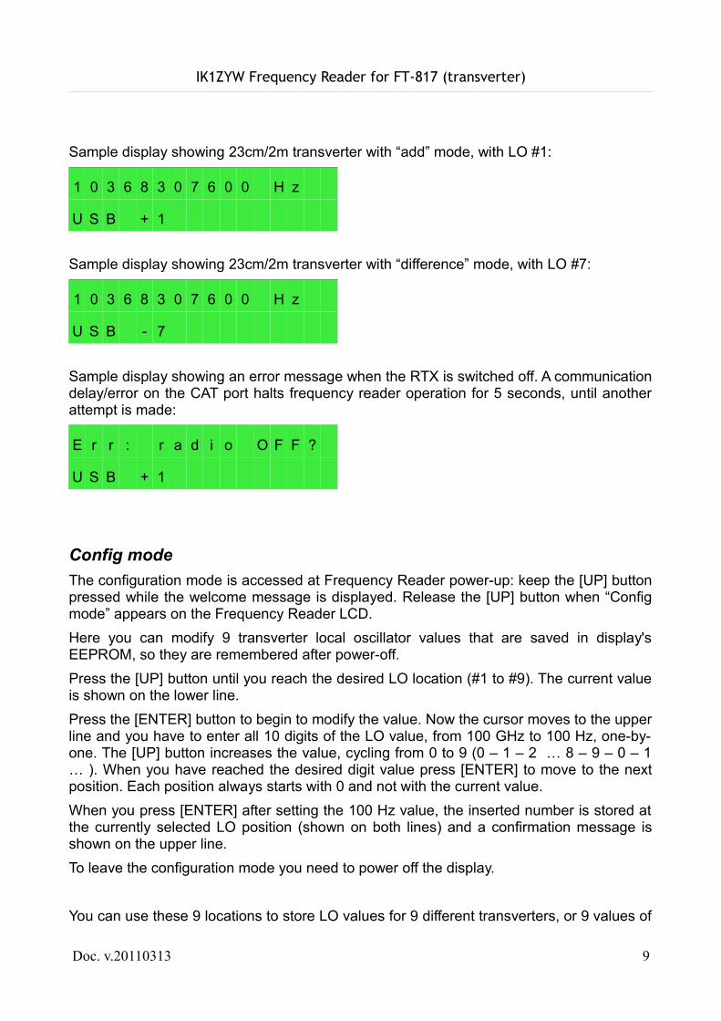
Sample display showing 23cm/2m transverter with “add” mode, with LO #1:
1 0 3 6 8 3 0 7 6 0 0 H z
U S B + 1
Sample display showing 23cm/2m transverter with “difference” mode, with LO #7:
1 0 3 6 8 3 0 7 6 0 0 H z
U S B - 7
Sample display showing an error message when the RTX is switched off. A communication delay/error on the CAT port halts frequency reader operation for 5 seconds, until another attempt is made:
E r r : r a d i o O F F ?
U S B + 1
Config modeThe configuration mode is accessed at Frequency Reader power-up: keep the [UP] button pressed while the welcome message is displayed. Release the [UP] button when “Config mode” appears on the Frequency Reader LCD.Here you can modify 9 transverter local oscillator values that are saved in display's EEPROM, so they are remembered after power-off.Press the [UP] button until you reach the desired LO location (#1 to #9). The current value is shown on the lower line.Press the [ENTER] button to begin to modify the value. Now the cursor moves to the upper line and you have to enter all 10 digits of the LO value, from 100 GHz to 100 Hz, one-by-one. The [UP] button increases the value, cycling from 0 to 9 (0 – 1 – 2 … 8 – 9 – 0 – 1 … ). When you have reached the desired digit value press [ENTER] to move to the next position. Each position always starts with 0 and not with the current value.When you press [ENTER] after setting the 100 Hz value, the inserted number is stored at the currently selected LO position (shown on both lines) and a confirmation message is shown on the upper line.To leave the configuration mode you need to power off the display.
You can use these 9 locations to store LO values for 9 different transverters, or 9 values of
Doc. v.20110313 9
IK1ZYW Frequency Reader for FT-817 (transverter)
one drifting LO. You don't need to set all of them: just set the first if you have only one transverter!
An example: set 10'224'123'600 Hz (for 10 GHz to 144 MHz) at #3 location.1. Power up the display keeping [UP] pressed => content of location #1 is shown2. press [UP] => content of location #2 is shown3. press [UP] => content of location #3 is shown4. press [ENTER] => the cursor goes on “G” of “GHzMHzkHzooo” string, showing “0”5. press [ENTER] => you are now on 10 GHz value, “0”6. press [UP] once to reach “1”7. press [ENTER] => you are now on 1 GHz value, “0”8. press [ENTER] => you are now on 100 MHz value, “0”9. press [UP] twice to reach “2”10.press [ENTER] => you are now on 10 MHz value, “0”11. press [UP] twice to reach “2”12.press [ENTER] => you are now on 1 MHz value, “0”13.press [UP] four times to reach “4”14.press [ENTER] => you are now on 100 kHz value, “0”15.press [UP] once to reach “1”16.press [ENTER] => you are now on 10 kHz value, “0”17.press [UP] twice to reach “2”18.press [ENTER] => you are now on 1 kHz value, “0”19.press [UP] three times to reach “3”20.press [ENTER] => you are now on 100 Hz value, “0”21.press [UP] six times to reach “6”22.press [ENTER] => the value gets stored at location #3
Tip. If you only need to show remotely what is shown on the actual display, without a transverter, set the LO value to 0000000000 Hz (10 times zero).
Difference modeIn “difference mode” the Frequency Reader circuit computes and displays LO-VFO instead of LO+VFO. This happens when your transverter LO is higher than its output frequency.To toggle between “difference” and “add” mode keep the [ENTER] button pressed during
Doc. v.20110313 10
IK1ZYW Frequency Reader for FT-817 (transverter)
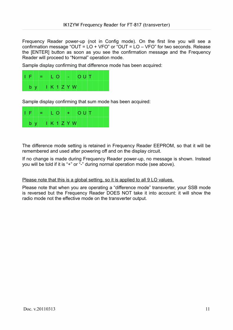
Frequency Reader power-up (not in Config mode). On the first line you will see a confirmation message “OUT = LO + VFO” or “OUT = LO – VFO” for two seconds. Release the [ENTER] button as soon as you see the confirmation message and the Frequency Reader will proceed to “Normal” operation mode.Sample display confirming that difference mode has been acquired:
I F = L O - O U T
b y I K 1 Z Y W
Sample display confirming that sum mode has been acquired:
I F = L O + O U T
b y I K 1 Z Y W
The difference mode setting is retained in Frequency Reader EEPROM, so that it will be remembered and used after powering off and on the display circuit.If no change is made during Frequency Reader power-up, no message is shown. Instead you will be told if it is “+” or “-” during normal operation mode (see above).
Please note that this is a global setting, so it is applied to all 9 LO values.Please note that when you are operating a “difference mode” transverter, your SSB mode is reversed but the Frequency Reader DOES NOT take it into account: it will show the radio mode not the effective mode on the transverter output.
Doc. v.20110313 11
IK1ZYW Frequency Reader for FT-817 (transverter)
CustomizingSince every microwave user probably has her/his own habits, it is possible to request some customization of the Frequency Reader firmware, up to the extent of available program memory. Send me a detailed description of your needs or request at
(mention “reader” in the subject line)
Sample customizations already tested:• automatic LO switch depending on the IF band (VHF/UHF)• transverter toggle output depending on the LO value selected• automatic VFO A/B setup to work with two transverters
Doc. v.20110313 12
ik1z y w @y a h o o .co m
IK1ZYW Frequency Reader for FT-817 (transverter)
SupportThis Frequency Reader contains a microprocessor that runs software. Even if all efforts have been made to produce a stable software, it can still contain bugs. Fortunately the microprocessor chip can be reprogrammed some thousand times with a simple hardware that connects to a computer parallel port. Updates to public firmware versions might be released in the future and announced on the IK1ZYW FT-817 Accessories home page (URL http://spazioinwind.libero.it/ik1zyw/hardware/keypad/index.html ).If you encounter an unexpected or undocumented behavior in your circuit please contact me at:
(mention “reader” in the subject line)
If you are not equipped to program your own chip I can send a preprogrammed item at live costs (offer subject to hardware and time availability). Feel free to add any amount of gratification for the research&development work done. Contact information as shown above.
Please also consider joining the keypad/reader reflector/mailing list at Yahoo! Groups:
http://groups.yahoo.com/group/817keypad/
Doc. v.20110313 13
ik1z y w @y a h o o .co m
IK1ZYW Frequency Reader for FT-817 (transverter)
Technical specifications
Core microprocessor Atmel ATmega168-20PUClock frequency 11.0592 MHz
Power supply 8 to 30 V DC (internally converted to 5V)Current T.B.D.
Communication protocol Serial at 0V/5V levels, Yaesu CATCommunication speed 9600 baud 8N2
Doc. v.20110313 14
IK1ZYW Frequency Reader for FT-817 (transverter)
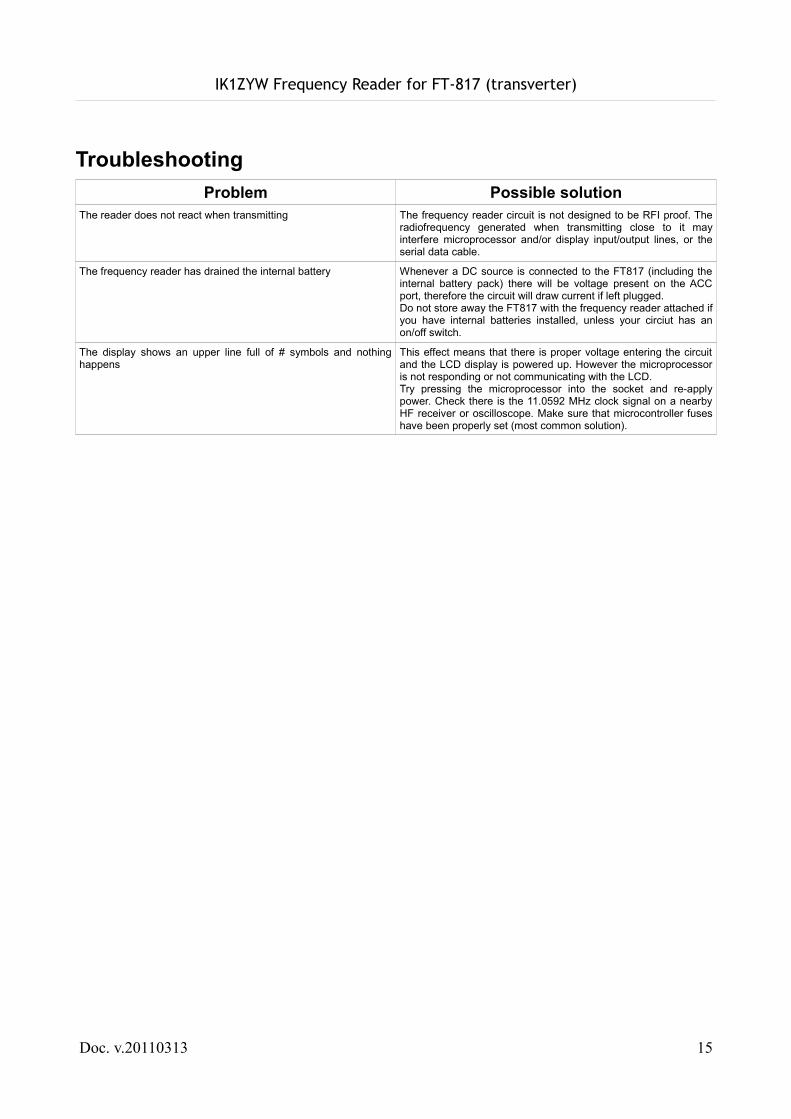
TroubleshootingProblem Possible solution
The reader does not react when transmitting The frequency reader circuit is not designed to be RFI proof. The radiofrequency generated when transmitting close to it may interfere microprocessor and/or display input/output lines, or the serial data cable.
The frequency reader has drained the internal battery Whenever a DC source is connected to the FT817 (including the internal battery pack) there will be voltage present on the ACC port, therefore the circuit will draw current if left plugged. Do not store away the FT817 with the frequency reader attached if you have internal batteries installed, unless your circiut has an on/off switch.
The display shows an upper line full of # symbols and nothing happens
This effect means that there is proper voltage entering the circuit and the LCD display is powered up. However the microprocessor is not responding or not communicating with the LCD.Try pressing the microprocessor into the socket and re-apply power. Check there is the 11.0592 MHz clock signal on a nearby HF receiver or oscilloscope. Make sure that microcontroller fuses have been properly set (most common solution).
Doc. v.20110313 15

IK1ZYW Frequency Reader for FT-817 (transverter)
Microcontroller choiceEven though the development platform uses an ATmega168, the current firmware size can fit in a ATmega48 chip. ATmega48, 88, 168 and 328 are pin-to-pin compatible, but carry a different memory size. You may try to use the provided firmware (for mega168) into another chip, or contact the author to get a custom compile for your device.If acquiring a chip, you are advised to buy at least an ATmega88 in order to have enough room for future developments, like the Interactive Frequency Reader.
Doc. v.20110313 16
IK1ZYW Frequency Reader for FT-817 (transverter)
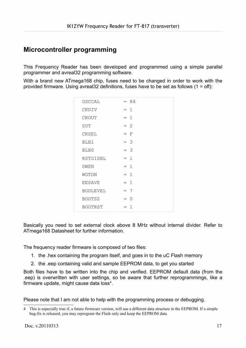
Microcontroller programming
This Frequency Reader has been developed and programmed using a simple parallel programmer and avreal32 programming software.With a brand new ATmega168 chip, fuses need to be changed in order to work with the provided firmware. Using avreal32 definitions, fuses have to be set as follows (1 = off):
Basically you need to set external clock above 8 MHz without internal divider. Refer to ATmega168 Datasheet for further information.
The frequency reader firmware is composed of two files:1. the .hex containing the program itself, and goes in to the uC Flash memory2. the .eep containing valid and sample EEPROM data, to get you started
Both files have to be written into the chip and verified. EEPROM default data (from the .eep) is overwritten with user settings, so be aware that further reprogrammings, like a firmware update, might cause data loss4.
Please note that I am not able to help with the programming process or debugging.
4 This is especially true if, a future firmware version, will use a different data structure in the EEPROM. If a simple bug-fix is released, you may reprogram the Flash only and keep the EEPROM data.
Doc. v.20110313 17
OSCCAL = 86 CKDIV = 1 CKOUT = 1 SUT = 2 CKSEL = F BLB1 = 3 BLB0 = 3 RSTDISBL = 1 DWEN = 1 WDTON = 1 EESAVE = 1 BODLEVEL = 7 BOOTSZ = 0 BOOTRST = 1
IK1ZYW Frequency Reader for FT-817 (transverter)
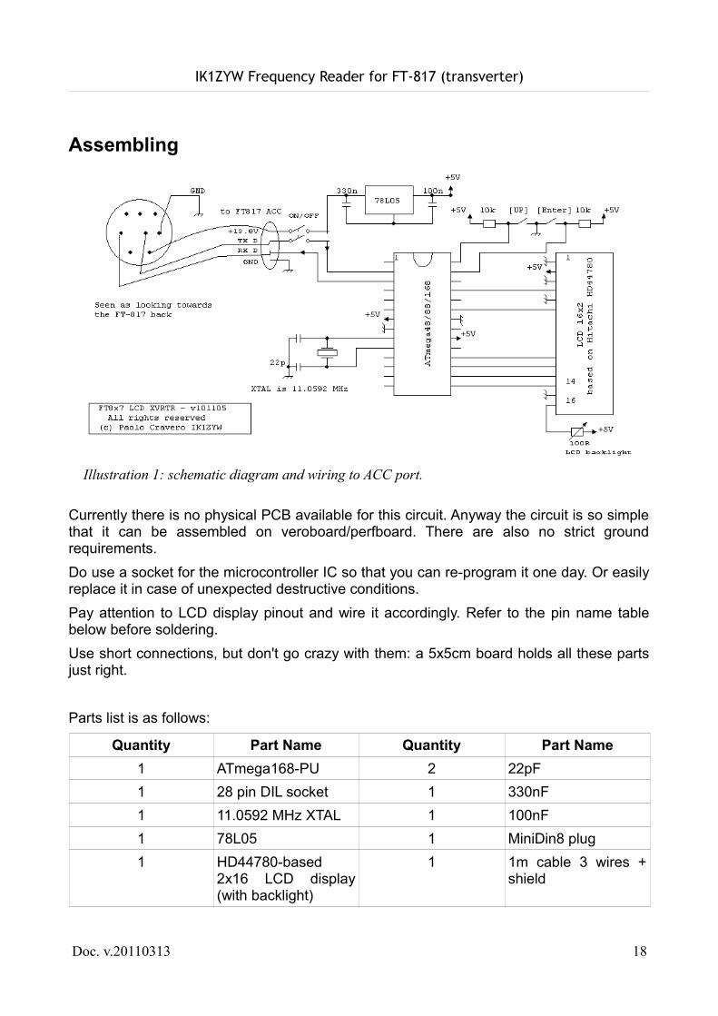
Assembling
Currently there is no physical PCB available for this circuit. Anyway the circuit is so simple that it can be assembled on veroboard/perfboard. There are also no strict ground requirements.Do use a socket for the microcontroller IC so that you can re-program it one day. Or easily replace it in case of unexpected destructive conditions.Pay attention to LCD display pinout and wire it accordingly. Refer to the pin name table below before soldering.Use short connections, but don't go crazy with them: a 5x5cm board holds all these parts just right.
Parts list is as follows:
Quantity Part Name Quantity Part Name1 ATmega168-PU 2 22pF1 28 pin DIL socket 1 330nF1 11.0592 MHz XTAL 1 100nF1 78L05 1 MiniDin8 plug1 HD44780-based
2x16 LCD display (with backlight)
1 1m cable 3 wires + shield
Doc. v.20110313 18
Illustration 1: schematic diagram and wiring to ACC port.
IK1ZYW Frequency Reader for FT-817 (transverter)
Optional parts make your Frequency Reader easier to handle and give it a more professional look:
Quantity Part Name Quantity Part Name1 DPST switch 1 16-way pin header
female (mount on main board)
1 16-way pin header male (mount on LCD)
1 4-way female connector
1 4-way male connector for PCB
10cm Heat-shrink 1mm pipe
1 Box, plastic or metal
You will also need some wire, at least in two different colors, a (max) 25/30W soldering iron and some solder.
WarningsLCD displays come in several flavors. The diagram above has been drawn according to the most common pin-out, but double-check your display pins layout with the way the Atmega48/88/168 expects them to be:
LCD pin name ATmega pin name ATmega pin numberDB4 PORTB.4 18DB5 PORTB.3 17DB6 PORTB.2 16DB7 PORTB.1 15E PORTC.0 23RS PORTC.2 25
You also need to pay attention to LCD's backlight. Some displays have anode and cathode reversed, so you better try it out before. Also take careful care to measure the required backlight current because the FT817 ACC port cannot source more than 100mA. Moreover 100mA continuous are the maximum limit for the 78L05 and it heats up alarmingly. So, if your LCD backlight is requiring more than 10-20mA, use an external power source (either for the backlight only, or the whole frequency reader) like a 9V PP3 battery and compute a proper series resistor.Also DO NOT replace the 78L05 with the more powerful 7805 unless you are using an external power source for the whole frequency reader.
Doc. v.20110313 19

IK1ZYW Frequency Reader for FT-817 (transverter)
ConnectionsIt is strongly advised to connect the Frequency Reader to the transceiver when no power is supplied to the radio, including internal batteries, unless you have installed an on/off switch. Remember that whenever a DC source is connected to the FT817 (including the internal battery pack) there will be voltage present on the ACC port, therefore the display circuit will draw current if left connected.
To LCDI have found that two 6-way pin headers (or a 16-way full row) produce a clean and sturdy connection between the keypad and the circuit. This way the circuit remains partially hidden under the LCD, therefore reducing the global footprint of the Frequency Reader.
To FT-817Depending on your choice of powering the keypad through the ACC port or an external battery, you need a cable with four or three wires respectively. I suggest using a shielded cable with three or two wires respectively.Use a 4-way PCB connector to easily remove the connecting cable from the circuit. Alternatively you can mount a 4-way panel socket and use a matching plug on one cable end.Towards the FT-817 cable end you need a MiniDin8 plug. Soldering into these requires a steady hand, some level of magnification and a thin iron tip. Get hold of some heatshrink pipe to protect your joints afterwards. Check with an ohm-meter for shorts between pins before using the cable. Good luck and remember I am not responsible for your faults.There are commercially available cables with MiniDin8 plugs, namely for an old Apple computer application. Sun SPARC stations keyboards also used them (but some plug modification is required). These cables offer the safety and ruggedness of a molded plug.
Doc. v.20110313 20
IK1ZYW Frequency Reader for FT-817 (transverter)
For FT-857/FT-897 OwnersI have been informed that FT-857 and FT-897 have a built-in function that does the transverter math. Since I do not own these transceivers, all I could do is read their instruction manuals.These settings are at Menu mode 089, 090 and 091. The manual states that these values can be set:Available Values: 00,000,00 ~ 9999,999,00 (kHz)I think this means from 0 Hz to 9.99999900 GHz, because Yaesu used the “,” both as thousands and decimal separator. So, if you own an 857/897 you will not need this Frequency Reader as long as your transverter works below 10 GHz and you don't need “difference” mode. Moreover, even if they allow two different values to be set, you have to enter the settings menu to switch between them.
Doc. v.20110313 21


![GN 817 GN 817 Indexing plungers INOX RoHS - Elesa 817.pdf · 2019. 11. 14. · GN 817-CK Code Description d1 Plunger -0.02 -0.04 Hole H7 d2 d3 k l1 l2 l3 l4 sw [N]* [N]# GN.41111](https://img.pdfslide.us/doc/110x75/5fceef3793732f2ac2563f82/gn-817-gn-817-indexing-plungers-inox-rohs-elesa-817pdf-2019-11-14-gn-817-ck.jpg)