Embed Size (px)
Citation preview

Less Info
Countries:
RUSSIA, AUSTRALIA, BAHAMAS, BOLIVIA,
BRAZIL, BELIZE, CANADA, CHILE, TAIWAN,
COLOMBIA, COSTA RICA, DOMINICAN
REPUBLIC, ECUADOR, EL SALVADOR,
TRINIDAD AND TOBAGO, UNITED STATES,
URUGUAY, VENEZUELA, MEXICO, ARUBA,
NICARAGUA, PERU, PUERTO RICO, Curaçao,
GUAM, GUATEMALA, GUYANA, HAITI,
HONDURAS, JAMAICA, KOREA, SOUTH
KOREA, NEW ZEALAND, PANAMA, SOUTH
AFRICA
Document ID: IK1400023
Availability: ISIS, Bus ISIS, FleetISIS, IsSIR Revision: 18
Major System: REAR AXLE Created: 9/4/2012
Current Language: English
Last Modified: 7/15/2019
Other Languages: Français, Español, Author: Gintarus
Andriusis
Viewed: 21399
Hide Details Coding Information
Copy Link Copy Relative Link Bookmark Add to Favorites Print Provide Feedback Helpful Not Helpful
View My Bookmarks 84 11
Title : Suspension Lean Diagnostics
Applies To : All Vehicles
Change Log
Dealers: Please refer to the change log text box below for recent changes to this article:
07/15/2018 ‐ Added new information to include CV Model units, also added a note that changing seats and plates can effect driveline angles, so measurements need to be taken. 11/06/2018 ‐ Reassigning to different owner 06/09/2016 ‐ Information added about induced leans under the "CAUTION:" tab. 12/14/2015 ‐ Part number change to show correct shim thickness. 11/30/2015 ‐ Added notes to all the work instructions. Added the notes to the IROS printable worksheet.
Description
This article addresses chassis lean conditions on all chassis. This does not include any diagnostics for body leans such as a cab lean. Keep in mind that a chassis lean may cause or accentuate a cab lean. Filling out the printable form and using the notes in blue will help you to determine the source of the lean and identify the action and parts required to correct the lean. If you are not able to come to a repair direction after completely following the article and filling out the form, please attach the form and requested photos to a case file for further assistance.
• For any lean issues with a front suspension rating of 8,000 LBS or less please refer to IK0300061 ‐ 8,000 LBS Front Suspension Lean Correction.
� IROS 4x2 chassis require the most measurements. A front shim, rear seat or frame issue are the possible repair paths depending on the measurements in all steps of the diagnostic form. It is critical to take accurate measurements for all steps to determine if the issue is being caused by the rear suspension.
◦ IROS 6x4 diagnostics does not include the pin bar height measurement. This is due to 4 points of contact to the frame for the rear suspension. Changing rear seats in an IROS equipped 6x4 will have minimal impact on a chassis lean.
� Other air suspensions designs do not allow the rear suspension to impact a front lean the way an IROS suspension can. As a result it has been found that a front shim or frame issue are the most common repair practices based on the results of the measurements.
� Vari‐Rate rear spring suspension can be shimmed in the front or rear to correct a lean. A shim or a frame repair are the most common repair practices based on the results of the measurements.
Page 1 of 13IK1400023 - Suspension Lean Diagnostics
8/2/2019https://evalue.internationaldelivers.com/service_kb/DocTool/ArticleViewer.aspx?ControlID...
� If you are unable to resolve the lean after completely following the iKNow article, please open a case file with the form completely filled out. Attach the form and the 4 requested photos to the case file.
CAUTION :
� Shimming is not an acceptable practice for chassis lean created by the addition of auxiliary equipment or loading practices resulting in vehicle lean. These procedures are intended to assist the service technician in making industry acceptable corrections for nominal lean issues and are not intended to compensate for over/uneven loading or un‐repaired vehicle damage ‐ regardless of cause.
� There is an orderable option that will in fact create a lean for a purpose to compensate a heavy body install (Cement Mixers, Snow Plows). If the unit is leaning, refer to the component section of the unit in Service Portal. This feature is added for most DuraStars with 8k front ends with batteries, DEF tank, Air Tanks, and Fuel Tank all on the Left side.
◦ 0003WAM ‐ Typically a 1" spacer is installed on the Front Left.◦ 0503013 ‐ Typically a 1/2" spacer is installed on the Front Left.
NOTE:
� On an air ride suspension, replacing the air spring or the MSM (main support member, aka � rear spring) will not have any effect on lean.
• Warranty will NOT COVER replacing a spring for the following complaints:
Weak spring Leaning
Bottoming out Lost arch
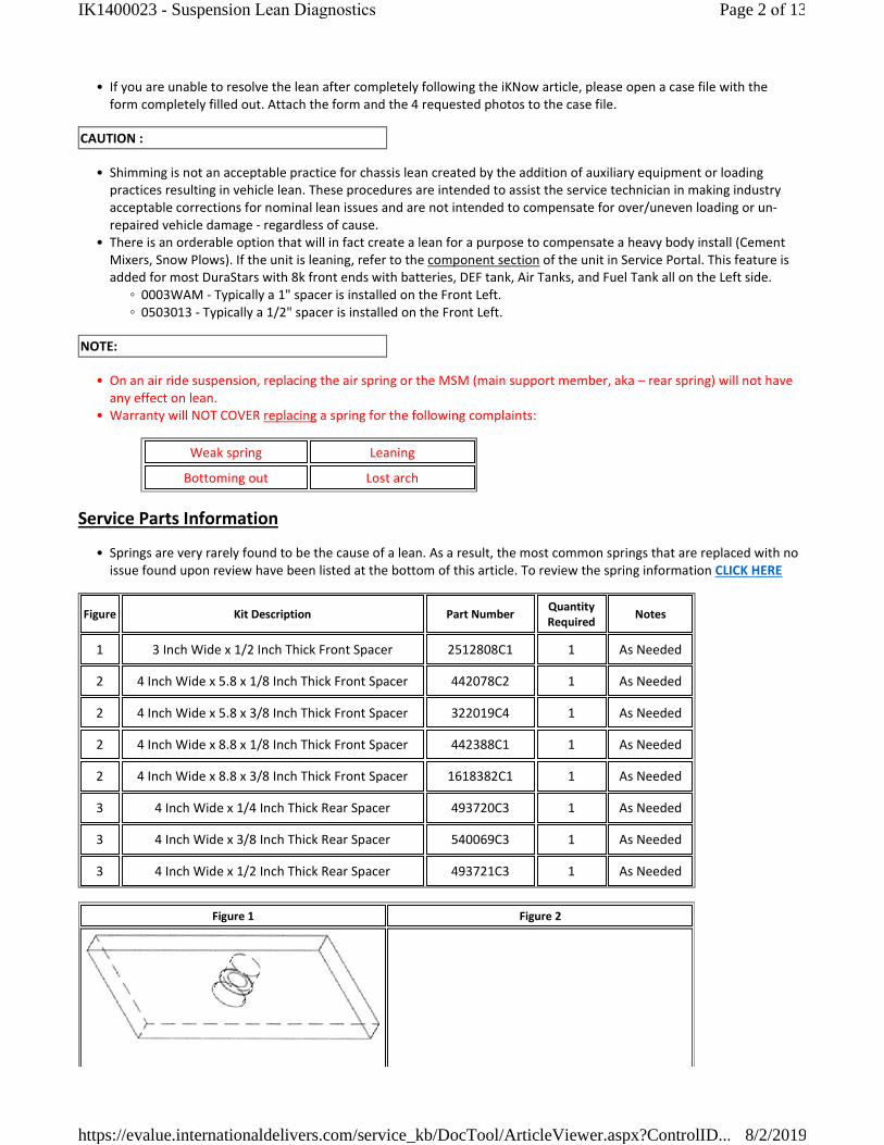
Service Parts Information
� Springs are very rarely found to be the cause of a lean. As a result, the most common springs that are replaced with no issue found upon review have been listed at the bottom of this article. To review the spring information CLICK HERE
Figure Kit Description Part NumberQuantity Required
Notes
1 3 Inch Wide x 1/2 Inch Thick Front Spacer 2512808C1 1 As Needed
2 4 Inch Wide x 5.8 x 1/8 Inch Thick Front Spacer 442078C2 1 As Needed
2 4 Inch Wide x 5.8 x 3/8 Inch Thick Front Spacer 322019C4 1 As Needed
2 4 Inch Wide x 8.8 x 1/8 Inch Thick Front Spacer 442388C1 1 As Needed
2 4 Inch Wide x 8.8 x 3/8 Inch Thick Front Spacer 1618382C1 1 As Needed
3 4 Inch Wide x 1/4 Inch Thick Rear Spacer 493720C3 1 As Needed
3 4 Inch Wide x 3/8 Inch Thick Rear Spacer 540069C3 1 As Needed
3 4 Inch Wide x 1/2 Inch Thick Rear Spacer 493721C3 1 As Needed
Figure 1 Figure 2
Page 2 of 13IK1400023 - Suspension Lean Diagnostics
8/2/2019https://evalue.internationaldelivers.com/service_kb/DocTool/ArticleViewer.aspx?ControlID...
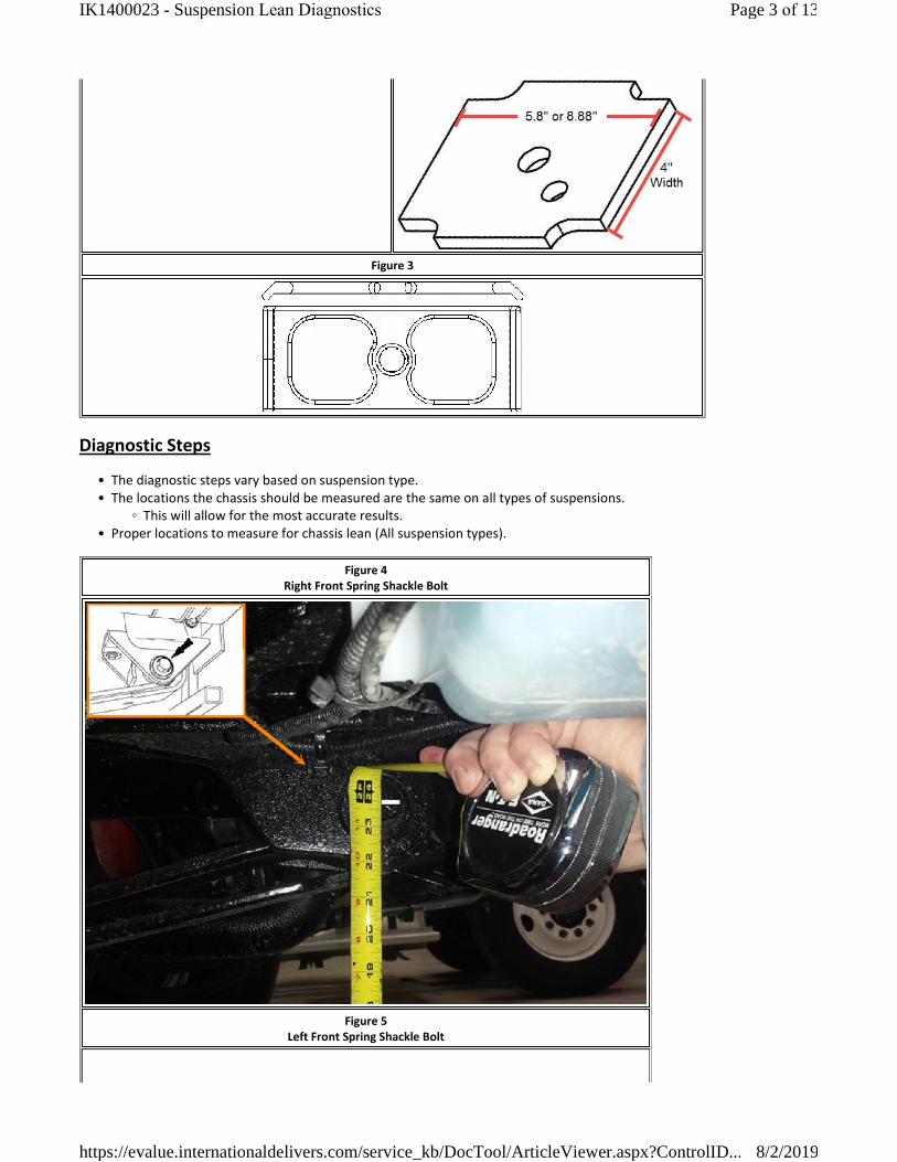
Figure 3
Diagnostic Steps
� The diagnostic steps vary based on suspension type.• The locations the chassis should be measured are the same on all types of suspensions.
◦ This will allow for the most accurate results. � Proper locations to measure for chassis lean (All suspension types).
Figure 4Right Front Spring Shackle Bolt
Figure 5Left Front Spring Shackle Bolt
Page 3 of 13IK1400023 - Suspension Lean Diagnostics
8/2/2019https://evalue.internationaldelivers.com/service_kb/DocTool/ArticleViewer.aspx?ControlID...

Figure 6Aft Frame Straight Truck
Figure 7Aft Frame Tractor
Page 4 of 13IK1400023 - Suspension Lean Diagnostics
8/2/2019https://evalue.internationaldelivers.com/service_kb/DocTool/ArticleViewer.aspx?ControlID...
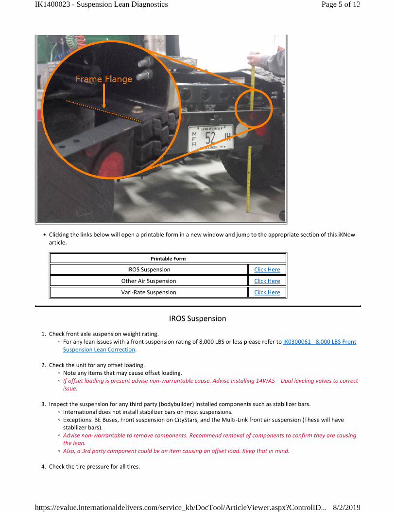
� Clicking the links below will open a printable form in a new window and jump to the appropriate section of this iKNow article.
Printable Form
IROS Suspension Click Here
Other Air Suspension Click Here
Vari‐Rate Suspension Click Here
IROS Suspension
1. Check front axle suspension weight rating. ◦ For any lean issues with a front suspension rating of 8,000 LBS or less please refer to IK0300061 ‐ 8,000 LBS Front
Suspension Lean Correction.
2. Check the unit for any offset loading. ◦ Note any items that may cause offset loading.◦ If offset loading is present advise non‐warrantable cause. Advise installing 14WAS � Dual leveling valves to correct
issue.
3. Inspect the suspension for any third party (bodybuilder) installed components such as stabilizer bars. ◦ International does not install stabilizer bars on most suspensions.◦ Exceptions: BE Buses, Front suspension on CityStars, and the Multi‐Link front air suspension (These will have
stabilizer bars).◦ Advise non‐warrantable to remove components. Recommend removal of components to confirm they are causing
the lean.◦ Also, a 3rd party component could be an item causing an offset load. Keep that in mind.
4. Check the tire pressure for all tires.
Page 5 of 13IK1400023 - Suspension Lean Diagnostics
8/2/2019https://evalue.internationaldelivers.com/service_kb/DocTool/ArticleViewer.aspx?ControlID...

◦ Adjust pressures if needed.◦ Record current tire pressures. ◦ It is recommended each axle be with 5% of each other. Especially if the lean is marginal.
5. Verify ride height is properly set per instructions below. ◦ Park the vehicle unloaded on a level surface with a light application of the brakes.◦ Do not apply the parking brake. Chock wheels to prevent vehicle movement.◦ Make sure 120 psi is in the vehicle air system, and then shut off engine.◦ Dump air from system, then re‐pressurize and allow it to return to the ride height.◦ Measurements are taken at the air spring assembly closest to the height control valve (usually forward left).◦ Measure the vertical distance from the bottom of the straight edge that is resting against the u‐bolts, to the bottommost position of the axle stop.
◦ There should be no angle created between the two measurement points.
Figure 8
◦ If you're outside the listed values on the table below, the height control valve will need to be adjusted. If adjustment is needed CLICK HERE
IROS Suspension Height Adjustment Specification Chart
IROS Suspension Feature Code Config ModelAxle Travel in Inches
(measured from axle stop, see Figure 2)
14UNN, 14UNM, 14UNL, 14UNS, 14UNT, 14UNU
6x4 All 2.75 ± 0.125 or 2 3/4 ± 1/8
14TBJ 4x2 7000, 8000, 9000 2.75 ± 0.125 or 2 3/4 ± 1/8
14TBJ, 14TBG, 14TBH, 14TBK, 14TBR, 14TBS, 14TBT
NOTE: For 14TBS, 14TBT Verify Model
4x2 3200, 4000. CE 200, CE 300, FE 300 3.0 ± 0.125 or 3 ± 1/8
Page 6 of 13IK1400023 - Suspension Lean Diagnostics
8/2/2019https://evalue.internationaldelivers.com/service_kb/DocTool/ArticleViewer.aspx?ControlID...

NOTE: Above Codes are not with 14WAW
14WAW (Flat Floor) 4x2 3000 2.7 ± 0.125 or 2 11/16 ± 1/8
14TBS, 14TBT
NOTE: For 14TBS, 14TBT Verify Model
4x2 RE 200, RE 300 2.375 ± 0.125 or 2 3/8 ± 1/8
14TBL, 14TBM, 14TBN
NOTE: Verify Build Date 4x2 4000
4.6 ± 0.125 or 4 5/8 ± 1/8
Models built before 02/23/2004
3.2 ± 0.125 or 3 3/16 ± 1/8
Models built starting 02/23/2004
14UNH 6x4 9000 1.55 ± 0.125 or 1 9/16 ± 1/8
14TBY 4x4 CXT, 7000 3.1 ± 0.125 or 3 3/32 ± 1/8
14TCH 4x2 TerraStar 3.0 ± 0.125 or 3 ± 1/8
14TCP, 14TCR 4x2 AE Bus 3.0 ± 0.125 or 3 ± 1/8
All dimensions are in inches
6. Once the proper ride height is set, and air bags are inflated with 120 psi, measure each corner of the vehicle as shown in Figures 4‐7 and record measurements.
◦ The front tires MUST be pointed straight forward to prevent any influence to the lean from King Pin Inclination.◦ Measure the front suspension at the spring shackle bolt as shown in Figures 4 and 5. Mark the bolt with a paint
pen so you have a reference point for future measurements that may be required.◦ Measure the rear of the vehicle at the aft frame flange (bottom of the flange) as shown in Figures 6 and 7. Location may vary slightly by application.
◦ If the lean is less than or equal to 3/8� Front and/or Rear, the vehicle is in spec. The repair is not warrantable. ◦ You can still advise on what repair would correct the lean, but at customer pay.
7. Dump the air from the suspension and verify the frame stop is touching the axle U‐bolt on both sides of the truck. The frame stop may not touch the U‐bolt on all vehicles. The space between the frame stop and U‐bolt should be even from the right to left side for those applications.
◦ Remeasure from the same locations used in Step 6 and record (Measurements are taken with suspension dumped).
◦ This will help show if the rear suspension is contributing to the lean (Especially 4x2 chassis), or help confirm a frame issue as the cause.
◦ Looking to see if opposite corners are still low (e.g. LF low RR low) which may help show a frame twist. Lean must be greater than 3/8".
◦ Looking to see if the rear goes into specification with suspension dumped. This may help show the Bar Pin Height is contributing, or show the frame is not twisted (Where a front shim may correct).
◦ If the front and rear both level out and the Bar Pin Height is not equal (Step 9) suspect an issue with a rear seat (4x2).
Re‐inflate the air suspension before continuing
8. Use a jack and place a 1 1/2" inch block under the Front tire with the lowest reading. (Do not drive the vehicle on to the block).
Page 7 of 13IK1400023 - Suspension Lean Diagnostics
8/2/2019https://evalue.internationaldelivers.com/service_kb/DocTool/ArticleViewer.aspx?ControlID...

◦ Remeasure from the bottom of the frame to ground and record. � This will show us how the rear suspension reacts and if shimming will help to correct the issue. (If the lean is prevalent in the front).
◦ Looking at the reaction in the rear here. (e.g. If the LF has a block, the weight transfer should cause the RR to be lower than the measurement at #6).
◦ Use this information together with #7. Suspension reaction with a block together with suspension difference when the suspension is dumped.
9. Measure from the center of the bar pin to the ground and record. (This step only applies to Single Rear Axle vehicles). ◦ Remove wooden block if previously installed.◦ You must remove the Spring Eye Bushing mounting bolts.◦ Using a frame jack at the rear of the vehicle, raise the frame evenly until the Bar Pin clears the Mounting Bracket
on both sides. • The rear tires should still be on the ground during this procedure. Only lift the rear of the frame until the Bar
Pin clears the mounting bracket.• This will help determine if there is an issue with a rear seat or rear seat mounting.
◦ See Figure 8 below.◦ Do not perform this step on 6x4 configurations.◦ If the Pin Bar Height is greater than 7/16� difference the repair will require changing a seat out on one side.◦ If the Pin Bar Height is 7/16� or less shimming the front suspension (steer axle) will be required to correct the lean.◦ You will need to watch what the result is in #8 closely when this measurement is off.
Figure 9
10. Record the axle seats degrees or part number on the physical part if possible. See Figure 10 and Figure 11 below. ◦ If a seat change is required to correct the lean, only change 1 seat size. (Only 1 seat will be replaced).◦ The seat that needs to be changed is the Pin Bar measurement that is smaller. (Only 1 seat will be replaced).◦ The change should increase the Pin Bar height on the Low Side. ◦ If the seat is changed, measure drive line angles BEFORE and AFTER as these measurements may change.
Page 8 of 13IK1400023 - Suspension Lean Diagnostics
8/2/2019https://evalue.internationaldelivers.com/service_kb/DocTool/ArticleViewer.aspx?ControlID...
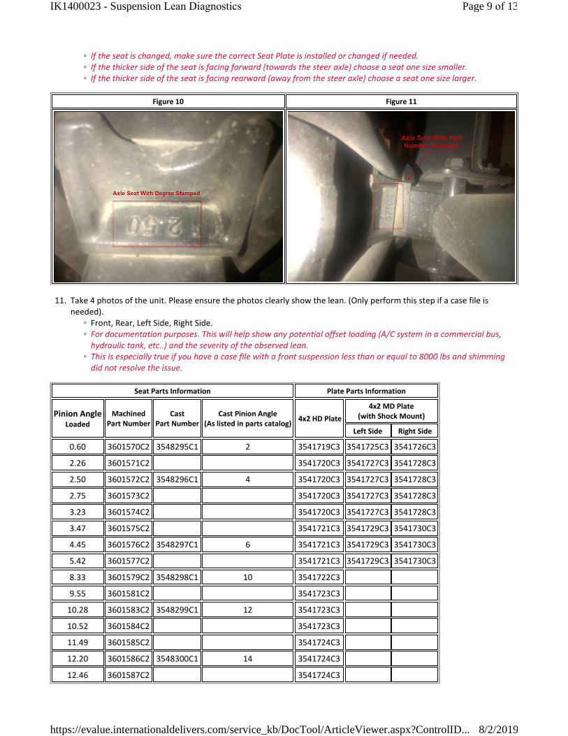
◦ If the seat is changed, make sure the correct Seat Plate is installed or changed if needed.◦ If the thicker side of the seat is facing forward (towards the steer axle) choose a seat one size smaller.◦ If the thicker side of the seat is facing rearward (away from the steer axle) choose a seat one size larger.
Figure 10 Figure 11
11. Take 4 photos of the unit. Please ensure the photos clearly show the lean. (Only perform this step if a case file is needed).
◦ Front, Rear, Left Side, Right Side.◦ For documentation purposes. This will help show any potential offset loading (A/C system in a commercial bus,
hydraulic tank, etc..) and the severity of the observed lean. ◦ This is especially true if you have a case file with a front suspension less than or equal to 8000 lbs and shimming
did not resolve the issue.
Seat Parts Information Plate Parts Information
Pinion AngleLoaded
MachinedPart Number
CastPart Number
Cast Pinion Angle(As listed in parts catalog)
4x2 HD Plate
4x2 MD Plate (with Shock Mount)
Left Side Right Side
0.60 3601570C2 3548295C1 2 3541719C3 3541725C3 3541726C3
2.26 3601571C2 3541720C3 3541727C3 3541728C3
2.50 3601572C2 3548296C1 4 3541720C3 3541727C3 3541728C3
2.75 3601573C2 3541720C3 3541727C3 3541728C3
3.23 3601574C2 3541720C3 3541727C3 3541728C3
3.47 3601575C2 3541721C3 3541729C3 3541730C3
4.45 3601576C2 3548297C1 6 3541721C3 3541729C3 3541730C3
5.42 3601577C2 3541721C3 3541729C3 3541730C3
8.33 3601579C2 3548298C1 10 3541722C3
9.55 3601581C2 3541723C3
10.28 3601583C2 3548299C1 12 3541723C3
10.52 3601584C2 3541723C3
11.49 3601585C2 3541724C3
12.20 3601586C2 3548300C1 14 3541724C3
12.46 3601587C2 3541724C3
Page 9 of 13IK1400023 - Suspension Lean Diagnostics
8/2/2019https://evalue.internationaldelivers.com/service_kb/DocTool/ArticleViewer.aspx?ControlID...
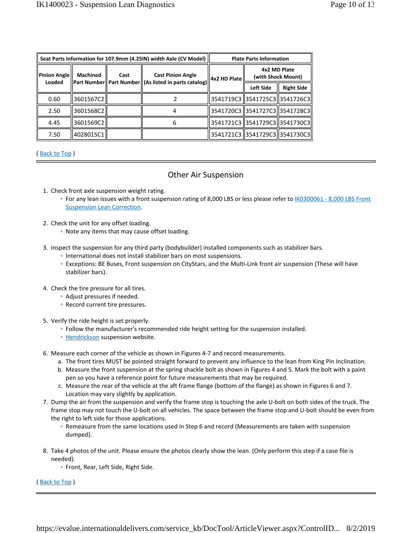
Seat Parts Information for 107.9mm (4.25IN) width Axle (CV Model) Plate Parts Information
Pinion AngleLoaded
MachinedPart Number
CastPart Number
Cast Pinion Angle(As listed in parts catalog)
4x2 HD Plate
4x2 MD Plate (with Shock Mount)
Left Side Right Side
0.60 3601567C2 2 3541719C3 3541725C3 3541726C3
2.50 3601568C2 4 3541720C3 3541727C3 3541728C3
4.45 3601569C2 6 3541721C3 3541729C3 3541730C3
7.50 4028015C1 3541721C3 3541729C3 3541730C3
( Back to Top )
Other Air Suspension
1. Check front axle suspension weight rating. ◦ For any lean issues with a front suspension rating of 8,000 LBS or less please refer to IK0300061 ‐ 8,000 LBS Front
Suspension Lean Correction.
2. Check the unit for any offset loading. ◦ Note any items that may cause offset loading.
3. Inspect the suspension for any third party (bodybuilder) installed components such as stabilizer bars. ◦ International does not install stabilizer bars on most suspensions.◦ Exceptions: BE Buses, Front suspension on CityStars, and the Multi‐Link front air suspension (These will have
stabilizer bars).
4. Check the tire pressure for all tires. ◦ Adjust pressures if needed.◦ Record current tire pressures.
5. Verify the ride height is set properly. ◦ Follow the manufacturer's recommended ride height setting for the suspension installed.◦ Hendrickson suspension website.
6. Measure each corner of the vehicle as shown in Figures 4‐7 and record measurements. a. The front tires MUST be pointed straight forward to prevent any influence to the lean from King Pin Inclination.b. Measure the front suspension at the spring shackle bolt as shown in Figures 4 and 5. Mark the bolt with a paint
pen so you have a reference point for future measurements that may be required.c. Measure the rear of the vehicle at the aft frame flange (bottom of the flange) as shown in Figures 6 and 7.
Location may vary slightly by application. 7. Dump the air from the suspension and verify the frame stop is touching the axle U‐bolt on both sides of the truck. The
frame stop may not touch the U‐bolt on all vehicles. The space between the frame stop and U‐bolt should be even from the right to left side for those applications.
◦ Remeasure from the same locations used in Step 6 and record (Measurements are taken with suspension dumped).
8. Take 4 photos of the unit. Please ensure the photos clearly show the lean. (Only perform this step if a case file is needed).
◦ Front, Rear, Left Side, Right Side.
( Back to Top )
Page 10 of 13IK1400023 - Suspension Lean Diagnostics
8/2/2019https://evalue.internationaldelivers.com/service_kb/DocTool/ArticleViewer.aspx?ControlID...

Vari‐Rate Spring Suspension
1. Check front axle suspension weight rating. ◦ For any lean issues with a front suspension rating of 8,000 LBS or less please refer to IK0300061 ‐ 8,000 LBS Front
Suspension Lean Correction.
2. Check the unit for any offset loading. ◦ Note any items that may cause offset loading.
3. Inspect the suspension for any third party (bodybuilder) installed components such as stabilizer bars. ◦ International does not install stabilizer bars on most suspensions.◦ Exceptions: BE Buses, Front suspension on CityStars, and the Multi‐Link front air suspension (These will have
stabilizer bars).
4. Check the tire pressure for all tires. ◦ Adjust pressures if needed.◦ Record current tire pressures.
5. Measure each corner of the vehicle as shown in Figures 4‐7 and record measurements. a. The front tires MUST be pointed straight forward to prevent any influence to the lean from King Pin Inclination.b. Measure the front suspension at the spring shackle bolt as shown in Figures 4 and 5. Mark the bolt with a paint
pen so you have a reference point for future measurements that may be required.c. Measure the rear of the vehicle at the aft frame flange (bottom of the flange) as shown in Figures 6 and 7.
Location may vary slightly by application.
6. Take 4 photos of the unit. Please ensure the photos clearly show the lean. (Only perform this step if a case file is needed).
◦ Front, Rear, Left Side, Right Side.
( Back to Top )
Measuring Spring Height
Below is the procedure to measure the most commonly replaced leaf springs on International trucks. If a leaf spring is in question for sagging, a lean, or a collapsed condition, then before the spring is replaced it should be measured. If the measurements taken on the spring are within the specifications shown below, then the spring is not causing the lean complaint or is not defective.
NOTE:
� It is common for springs to be flat or have a negative arch when loaded. ◦ The springs are designed this way, and it is all based on the spring rate.
Measurement Technique
The measurements below are with the spring in a free, unloaded state. This is known as free camber. To make these measurements, the spring must be removed from the vehicle. Use a piece of straight metal or a line, and place it between the centers of the 2 eyelets. Use a square to measure 90 degrees of the center of the top of the spring to the center line.
Dual Eye Leaf Spring Measurements
Page 11 of 13IK1400023 - Suspension Lean Diagnostics
8/2/2019https://evalue.internationaldelivers.com/service_kb/DocTool/ArticleViewer.aspx?ControlID...
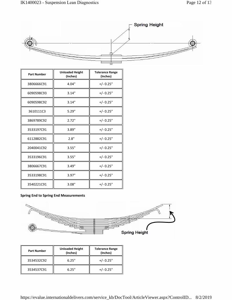
Part NumberUnloaded Height
(Inches)Tolerance Range
(Inches)
3806666C91 4.04" +/‐ 0.25"
6090598C93 3.14" +/‐ 0.25"
6090598C92 3.14" +/‐ 0.25"
3610111C3 5.29" +/‐ 0.25"
3869789C92 2.72" +/‐ 0.25"
3533197C91 3.89" +/‐ 0.25"
6112882C91 2.8" +/‐ 0.25"
2040041C92 3.55" +/‐ 0.25"
3533196C91 3.55" +/‐ 0.25"
3806667C91 3.49" +/‐ 0.25"
3533198C91 3.97" +/‐ 0.25"
3540221C91 3.08" +/‐ 0.25"
Spring End to Spring End Measurements
Part NumberUnloaded Height
(Inches)Tolerance Range
(Inches)
3534532C92 6.25" +/‐ 0.25"
3534537C91 6.25" +/‐ 0.25"
Page 12 of 13IK1400023 - Suspension Lean Diagnostics
8/2/2019https://evalue.internationaldelivers.com/service_kb/DocTool/ArticleViewer.aspx?ControlID...
Hide Details Feedback Information
Viewed: 21398
Helpful: 84
Not Helpful: 11
No Feedback Found
Copyright © 2019 Navistar, Inc.
( Back to Top )
Other Resources
� Master Service Information Page
Page 13 of 13IK1400023 - Suspension Lean Diagnostics
8/2/2019https://evalue.internationaldelivers.com/service_kb/DocTool/ArticleViewer.aspx?ControlID...