Embed Size (px)
Citation preview
IJITE Vol.04 Issue-03, (March, 2016) ISSN: 2321-1776 International Journal in IT and Engineering, Impact Factor- 5.343
A Monthly Double-Blind Peer Reviewed Refereed Open Access International e-Journal - Included in the International Serial Directories
International Journal in IT and Engineering http://www.ijmr.net.in email id- [email protected] Page 18
Security Using Hiding Technique : EOB Case Study
Prof. Mohamed Osama Khozium Department of Engineering and applied science - computers, MCC-UQU.
Umm Al-Qura University, Makkah, Saudi Arabia
Abstract The proliferation of modern electronically controlled, directed, and commanded
weapons has caused a rapid expansion in the field of science which is generally
called electronic warfare (EW). The basic concept of EW is to exploit the enemy's
electromagnetic emissions in all parts of the electromagnetic spectrum in order to
provide intelligence on the enemy's order of battle ( ORBTA ), intentions, and
capabilities. This paper introduce electronic order of battle (EOB) and it's features
and explain what does it mean by steganography and how to use it not only in EOBs
storage management but also to secure the EOB and concentrate it to be used by only
the concerned commanders and headquarters in simply, easy, accurate and secured
way. Paper will explain deeply proposed software using steganography to hid a lot of
EOBs in one base map and how can each commander retrieve his own EOB.
Headquarters can retrieve any EOBs from the same base map. Some code will be
highlighted and included in the paper.
Keywards : electronic warfare, order of battle, steganography, security.
I . INTRODUCTION Situational Awareness (SA), Electronic Order of Battle (EOB), and Common
Operating Picture (COP) are all terms used to describe getting tactical information
into the hands of the warfighter [1]. The Electronic Order of Battle (EOB) details all
known combinations of emitters and platforms in a particular Area of Responsibility.
for both Blue (enemy) and Red (friend) force data. On today's modern battlefield an
EOB can present a very complex and potentially confusing picture to the
commanders. Consequently, some method of presenting the EOB in a way readily
assimilated by operators amongst the myriad data presented to them during pre-
mission briefings is required. It is believed that steganography approach could be used
to enhance the presentation of EOBs and assist commanders to better understand and
retain the data presented [2]. Steganography is the art and science of hiding the
existence of information [3]. In our research we will use it to conceal all the EOBs
inside one map and show the only required EOB for each commanders to make
concentrations for the data and prevent any confusion in addition to storage
management and security issues.….
In this paper, we focus on the meaning of order of battle and its importance to the
electronic warfare. The definition, history and techniques of steganography will be
highlighted. We attempt to identify the problems which encounter the commanders to
read and understand EOBs including the storage management problem, then we
provide solution to some of these problems.
The rest of the paper is organized as follows. The next section provide overview on
Electronic warfare and electronic order of battle (EOB) and discuss the problems
encounter commanders to read and understanding EOBs. Section three will highlight
the steganography meaning, history and some used techniques. In section four we will
describe the proposed software using steganography as an approach to solve some of
the mentioned problems. While section five concludes the paper.
IJITE Vol.04 Issue-03, (March, 2016) ISSN: 2321-1776 International Journal in IT and Engineering, Impact Factor- 5.343
A Monthly Double-Blind Peer Reviewed Refereed Open Access International e-Journal - Included in the International Serial Directories
International Journal in IT and Engineering http://www.ijmr.net.in email id- [email protected] Page 19
2. Overview on Electronic Warfare and EOB.
2.1 Electronic Warfare:
A general term used to describe the use of communications systems in warfare. As
such, electronic warfare includes the Electronic Order of Battle (EOB),
reconnaissance, intentional interference, intrusion or intelligence collection[5]
Electronic warfare is a military action where the objective is to control the
electromagnetic spectrum [6] To accomplish this, both offensive electronic attack
(electronic countermeasure) and defensive electronic protection (electronic counter-
countermeasure) are required. In addition, electronic warfare support (electronic
support measure) actions are necessary to supply the intelligence and threat
recognition that allow implementation of both electronic attack and protection.
EW now is commonly divided into three subfields. Electronic support (ES), electronic
attack(EA) and electronic protection(EP).
2.2Electronic Support [7]:
Electronic support (ES), previously known as electronic support measures (ESM), is
considered the eyes and ears of the EW effort, in that Electronic Support is
responsible for the detection, processing, recording and identification of
electromagnetic energy transmitted by hostile, friendly and neutral radar systems. The
main aim of Electronic Support is to gain sufficient information about radar sensors to
allow an understanding of the radar’s characteristics including its role, its method of
operation, and its strengths and weaknesses. With this information, the Electronic
Support system can identify the radar, assess its relative threat and provide
information to the operator on how best to manage the radar’s presence.
Many factors impact on the effectiveness of Electronic Support, but all factors can
be grouped into one of the following categories:
transmitter characteristics including transmitted power, operating frequency,
polarization, signal bandwidth;
transmitting antenna characteristics including beamwidth, sidelobe levels, and
scan patterns;
environmental characteristics between the radar and the Electronic Support
equipment including atmospheric and meteorological conditions; and
the capability of the Electronic Support equipment including the receiving
antenna characteristics, and the receiver capabilities and sensitivity.
Electronic Support is a passive activity as the Electronic Support equipment
does not transmit any electromagnetic energy in the performance of its roles. It is
important that the adversary remains unaware of the ES activity, because there are
many tactics an adversary radar system can employ to make the Electronic
Support role even more difficult than it is normally. Additionally, remaining
passive lessens the opportunity for the adversary radar to plant false information
into the transmissions in an attempt to corrupt or confuse the Electronic Support
effort.
IJITE Vol.04 Issue-03, (March, 2016) ISSN: 2321-1776 International Journal in IT and Engineering, Impact Factor- 5.343
A Monthly Double-Blind Peer Reviewed Refereed Open Access International e-Journal - Included in the International Serial Directories
International Journal in IT and Engineering http://www.ijmr.net.in email id- [email protected] Page 20
2.1.2 Electronic Attack [8]
Electronic attack (EA), previously known as electronic counter measures (ECM), is
conducted on radar systems to reduce or prevent the radar’s use of the
electromagnetic spectrum effectively. This chapter investigates the process of
performing Electronic Attack, reviews the major Electronic Attack tactics that can be
employed and then reviews the major Electronic Attack tools available to the
operator.
Enemy sensors are the main focus of Electronic Attack action. Active sensors are
particularly vulnerable as these sensors are designed to transmit and receive
electromagnetic energy. Electronic Attack tactics and tools look to exploit active
sensors by analyzing the transmission (ES) and then attacking the receiver.
Electronic Attack can be conducted against all electromagnetic systems including
communications systems. The coverage of Electronic Attack in this text is limited to
radar Electronic Attack. Radar systems are operated to detect, acquire and track
targets with the ultimate view to engaging and destroying the target. To that end,
interfering and degrading the performance of radar systems is often of critical value to
the targeted platform’s survival and ability to carry out its intended role.
2.1.3 Electronic Protection
The main aim of electronic protection (EP), previously known as electronic counter
counter measures (ECCM), is to ensure continued friendly use of the electromagnetic
spectrum despite adversary EA and ES. Countering EA efforts is the main focus of
electronic protection although some electronic protection techniques are also designed
to make adversary ES more challenging.
EP and EA fields tend to be complimentary and reactive fields of endeavor in that
an advance in technology and techniques in one field necessarily results in research,
development and advancement in the other.
The designers of military radar systems must assume that their systems operate in
the most hostile of electronic environments and must, therefore design the radar with
EA and electronic protection in mind. Electronic protection is not solely a military
concern, however. Civilian radar systems also have to operate in hostile electronic
environments and must therefore have EP built in. The civilian environment is often
hostile due to the operation of other radar and electromagnetic systems in the same
physical location as the radar system. Electronic protection techniques developed for
the military domain can allow civilian radars to operate in the presence of other
sources of potentially disruptive electromagnetic energy.
2.1.4 Types of radar from EW point of view [9,10].
We will classify radar in terms of the tasks that they perform. Each radar type has
characteristics that strongly affect the way it interacts with EW systems, and hence
the way they are represented in EW.
* Search Radar
Search radar are sometimes called early warning radar. These radar
typically have very long range. They are at relatively low frequencies and
have long pulse duration. Standoff jamming is the best technique to deal
with early warning radar.
IJITE Vol.04 Issue-03, (March, 2016) ISSN: 2321-1776 International Journal in IT and Engineering, Impact Factor- 5.343
A Monthly Double-Blind Peer Reviewed Refereed Open Access International e-Journal - Included in the International Serial Directories
International Journal in IT and Engineering http://www.ijmr.net.in email id- [email protected] Page 21
* Tracking radar
Tracking radar provide sufficiently high location accuracy and frequent
location updates to allow weapons to engage their targets. Tracking radar
typically operate at higher frequencies than early warning radar. They also
have shorter pulses and higher pulse repetition rates. They are designed to
operate over a little more than the lethal range of the weapons they support.
Acquisition radar and fire control radar are examples of tracking radar. Self
protection jamming is the best technique to deal with tracking radar.
2.1.5 Fundamental Equations for radar ranges [11,12].
2.1.5.1 To calculate Radar Range
R =
Where ;
R = Radar detection range in Km
Pt = Radar Transmitted Power in watt
Gt = Antenna Gain in db
Ae= Antenna Effective Area =
λ = Wave length in m
σ = Target radar cross section area in m²
S = Min Received signal (sensitivity ) in watt
π = Constant = 3.14
2.1.5.2 To calculate Burn Through Range
R² =
R = Jammer effective range in Km
PJ = Jammer Transmitted Power in watt
GJ = Antenna Gain in db
BWJ = Jammer band in MHz
BWR = Radar Receiver band in MHz
2.2 AN ORDER OF BATTLE (often abbreviated as ORBAT, OOB, O/B, or OB)
is an organizational tool used by military intelligence to list and analyze enemy
military units. In United States Army practice, an order of battle should relate what an
American unit might be expected to encounter while on field operations. Orders of
battle analyze enemy units, personnel, and equipment [13]
G λ²
4 π
4 Pt Gt Ae σ
(4 π ) ² S
Pt Gt σ BWJ
PJ GJ BWR 4 π
IJITE Vol.04 Issue-03, (March, 2016) ISSN: 2321-1776 International Journal in IT and Engineering, Impact Factor- 5.343
A Monthly Double-Blind Peer Reviewed Refereed Open Access International e-Journal - Included in the International Serial Directories
International Journal in IT and Engineering http://www.ijmr.net.in email id- [email protected] Page 22
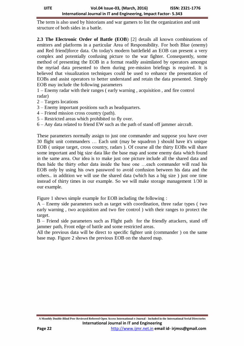
The term is also used by historians and war gamers to list the organization and unit
structure of both sides in a battle.
2.3 The Electronic Order of Battle (EOB) [2] details all known combinations of
emitters and platforms in a particular Area of Responsibility. For both Blue (enemy)
and Red friend)force data. On today's modern battlefield an EOB can present a very
complex and potentially confusing picture to the war fighter. Consequently, some
method of presenting the EOB in a format readily assimilated by operators amongst
the myriad data presented to them during pre-mission briefings is required. It is
believed that visualization techniques could be used to enhance the presentation of
EOBs and assist operators to better understand and retain the data presented. Simply
EOB may include the following parameters
1 – Enemy radar with their ranges ( early warning , acquisition , and fire control
radar)
2 – Targets locations
3 – Enemy important positions such as headquarters.
4 – Friend mission cross country (path).
5 – Restricted areas which prohibited to fly over.
6 – Any data related to friend EW such as the path of stand off jammer aircraft.
These parameters normally assign to just one commander and suppose you have over
30 flight unit commanders … Each unit (may be squadron ) should have it's unique
EOB ( unique target, cross country, radars ). Of course all the thirty EOBs will share
some important and big size data like the base map and some enemy data which found
in the same area. Our idea is to make just one picture include all the shared data and
then hide the thirty other data inside the base one …each commander will read his
EOB only by using his own password to avoid confusion between his data and the
others.. in addition we will use the shared data (which has a big size ) just one time
instead of thirty times in our example. So we will make storage management 1/30 in
our example.
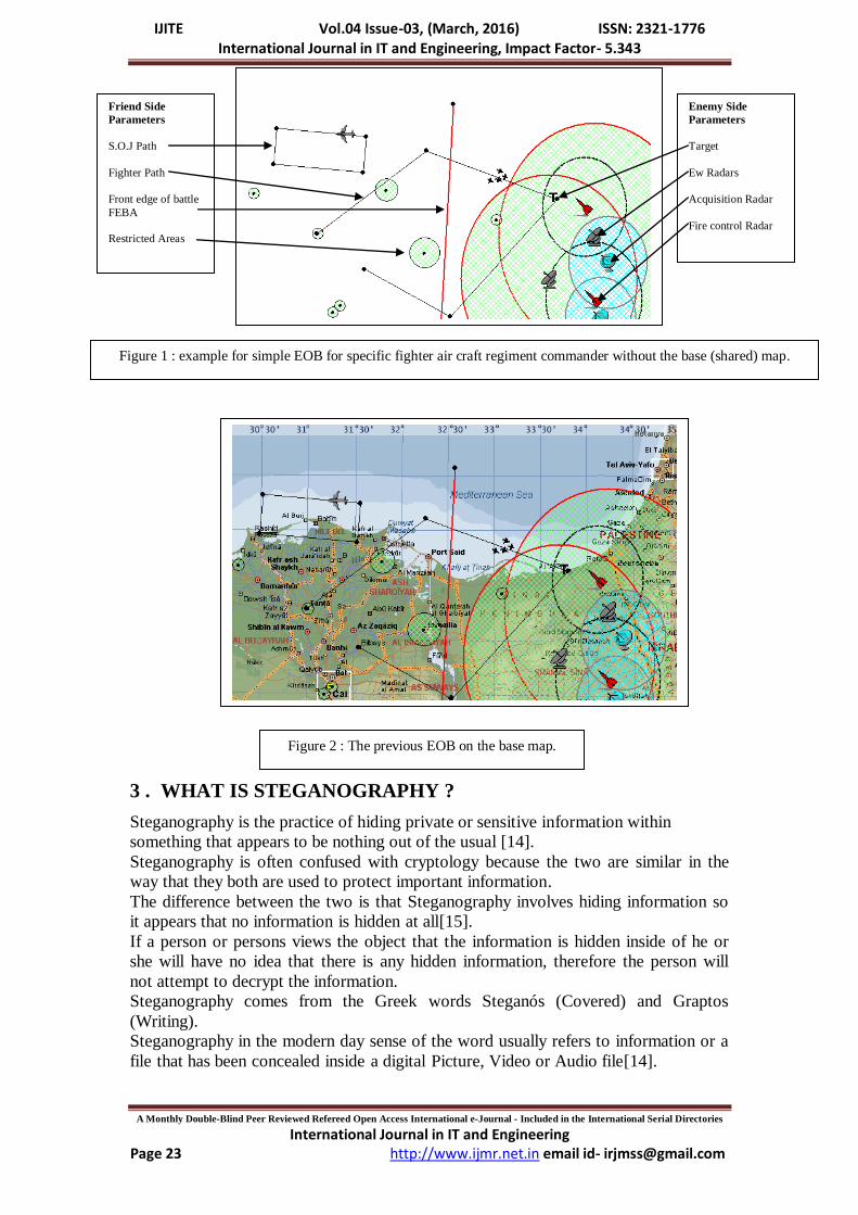
Figure 1 shows simple example for EOB including the following :
A – Enemy side parameters such as target with coordination, three radar types ( two
early warning , two acquisition and two fire control ) with their ranges to protect the
target.
B – Friend side parameters such as Flight path for the friendly attackers, stand off
jammer path, Front edge of battle and some restricted areas.
All the previous data will be direct to specific fighter unit (commander ) on the same
base map. Figure 2 shows the previous EOB on the shared map.
IJITE Vol.04 Issue-03, (March, 2016) ISSN: 2321-1776 International Journal in IT and Engineering, Impact Factor- 5.343
A Monthly Double-Blind Peer Reviewed Refereed Open Access International e-Journal - Included in the International Serial Directories
International Journal in IT and Engineering http://www.ijmr.net.in email id- [email protected] Page 23
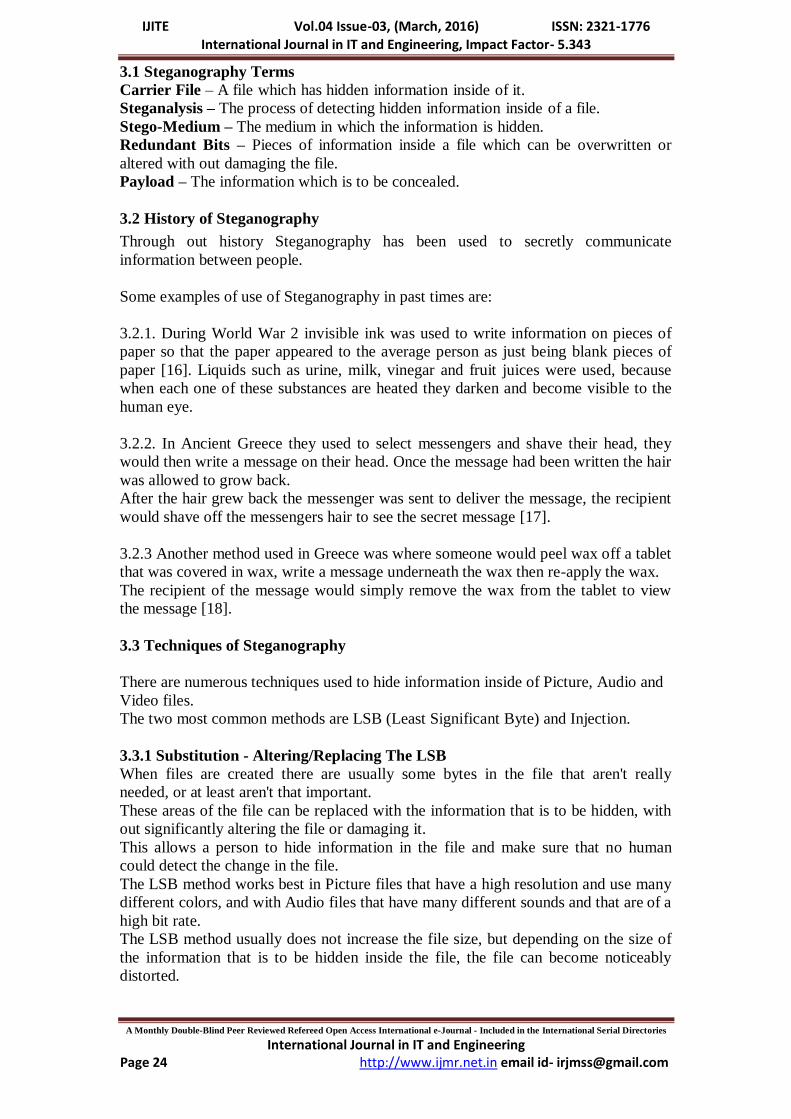
3 . WHAT IS STEGANOGRAPHY ?
Steganography is the practice of hiding private or sensitive information within
something that appears to be nothing out of the usual [14].
Steganography is often confused with cryptology because the two are similar in the
way that they both are used to protect important information.
The difference between the two is that Steganography involves hiding information so
it appears that no information is hidden at all[15].
If a person or persons views the object that the information is hidden inside of he or
she will have no idea that there is any hidden information, therefore the person will
not attempt to decrypt the information.
Steganography comes from the Greek words Steganós (Covered) and Graptos
(Writing).
Steganography in the modern day sense of the word usually refers to information or a
file that has been concealed inside a digital Picture, Video or Audio file[14].
Enemy Side
Parameters
Target
Ew Radars
Acquisition Radar
Fire control Radar
Friend Side
Parameters
S.O.J Path
Fighter Path
Front edge of battle
FEBA
Restricted Areas
Figure 1 : example for simple EOB for specific fighter air craft regiment commander without the base (shared) map.
Figure 2 : The previous EOB on the base map.
IJITE Vol.04 Issue-03, (March, 2016) ISSN: 2321-1776 International Journal in IT and Engineering, Impact Factor- 5.343
A Monthly Double-Blind Peer Reviewed Refereed Open Access International e-Journal - Included in the International Serial Directories
International Journal in IT and Engineering http://www.ijmr.net.in email id- [email protected] Page 24
3.1 Steganography Terms
Carrier File – A file which has hidden information inside of it.
Steganalysis – The process of detecting hidden information inside of a file.
Stego-Medium – The medium in which the information is hidden.
Redundant Bits – Pieces of information inside a file which can be overwritten or
altered with out damaging the file.
Payload – The information which is to be concealed.
3.2 History of Steganography
Through out history Steganography has been used to secretly communicate
information between people.
Some examples of use of Steganography in past times are:
3.2.1. During World War 2 invisible ink was used to write information on pieces of
paper so that the paper appeared to the average person as just being blank pieces of
paper [16]. Liquids such as urine, milk, vinegar and fruit juices were used, because
when each one of these substances are heated they darken and become visible to the
human eye.
3.2.2. In Ancient Greece they used to select messengers and shave their head, they
would then write a message on their head. Once the message had been written the hair
was allowed to grow back.
After the hair grew back the messenger was sent to deliver the message, the recipient
would shave off the messengers hair to see the secret message [17].
3.2.3 Another method used in Greece was where someone would peel wax off a tablet
that was covered in wax, write a message underneath the wax then re-apply the wax.
The recipient of the message would simply remove the wax from the tablet to view
the message [18].
3.3 Techniques of Steganography
There are numerous techniques used to hide information inside of Picture, Audio and
Video files.
The two most common methods are LSB (Least Significant Byte) and Injection.
3.3.1 Substitution - Altering/Replacing The LSB
When files are created there are usually some bytes in the file that aren't really
needed, or at least aren't that important.
These areas of the file can be replaced with the information that is to be hidden, with
out significantly altering the file or damaging it.
This allows a person to hide information in the file and make sure that no human
could detect the change in the file.
The LSB method works best in Picture files that have a high resolution and use many
different colors, and with Audio files that have many different sounds and that are of a
high bit rate.
The LSB method usually does not increase the file size, but depending on the size of
the information that is to be hidden inside the file, the file can become noticeably
distorted.
IJITE Vol.04 Issue-03, (March, 2016) ISSN: 2321-1776 International Journal in IT and Engineering, Impact Factor- 5.343
A Monthly Double-Blind Peer Reviewed Refereed Open Access International e-Journal - Included in the International Serial Directories
International Journal in IT and Engineering http://www.ijmr.net.in email id- [email protected] Page 25
3.3.2 Injection
Injection is quite a simple method which simply involves directly injecting the secret
information into the carrier file.
The main problem with this method is that it can significantly increase the size of the
carrier file.
4. THE PROPOSED SYSTEM.
In the following section we will give example of hide three EOBs (payloads)
inside one map picture (carrier file) we will use the terminology of Steganography as
mentioned in section 3.1 such as carrier file and payload. Then we will show how to
increase the three payloads to be thirty or what ever.
4.1 The idea of the proposed system :
A digitized photograph is stored as an array of colored dots, called pixels.
Each pixel typically has three numbers associated with it, one each for red, green, and
blue intensities, and these values often range from 0-255 [19]. We consider that we
have three payloads (each one will be related to one color red, green and blue), and
we have one carrier file (base map). We will check how many color in each payload.
Suppose we find five colors …we go to the carrier and recoloring it to make five
colors available in the red, green and blue ….The red for the first payload, the green
for the second payload and the blue for the third pay load….. The recoloring for the
red color means make five number available for the first payload …for example the
red color number varies from 0 to 255….in each pixel…we have x = 5 then the red
numbers will be 0,6,12, 18 and so on. In specific pixel in the carrier file we find that
the red color has number of 0 then no problem…if it has number of 1 then we recolor
it to 0…if it has number of 16 then we will recolor it to 18 and so on. These
recoloring will not affect the color of the carrier proving the colors of the payloads
are is not exceed specific number which shown in the table…then we check if the first
payload has a color in this pixel and his color is the first color (from the five color)
then it will take the reference of 1or 7 or 13 and so on..if the payload has nothing in
this pixel …there is no reference. This means we have three operations get color, filter
colors and hide image and we will explain each stage in brief :
Stage 1 : Get colors
Aim: Scanning all images and list all colors exists in them in ColorsList.
Stage 2 : Filter colors
Aim: Scanning the base image and recoloring all pixels.
Steps:
1. Consider that the numbers of colors in ColorList=N.
2. The system change red channel value of each pixel to nearest (N+1)*i
value where 0 <= i <= 255/(N+1).
3. The system change green channel value of each pixel to nearest (N+1)*i
value where 0 <= i <= 255/(N+1).
4. The system change blue channel value of each pixel to nearest (N+1)*i
value where 0 <= i <= 255/(N+1).
Stage 3 : Hiding images
Aim: Hiding images in the base image.
IJITE Vol.04 Issue-03, (March, 2016) ISSN: 2321-1776 International Journal in IT and Engineering, Impact Factor- 5.343
A Monthly Double-Blind Peer Reviewed Refereed Open Access International e-Journal - Included in the International Serial Directories
International Journal in IT and Engineering http://www.ijmr.net.in email id- [email protected] Page 26
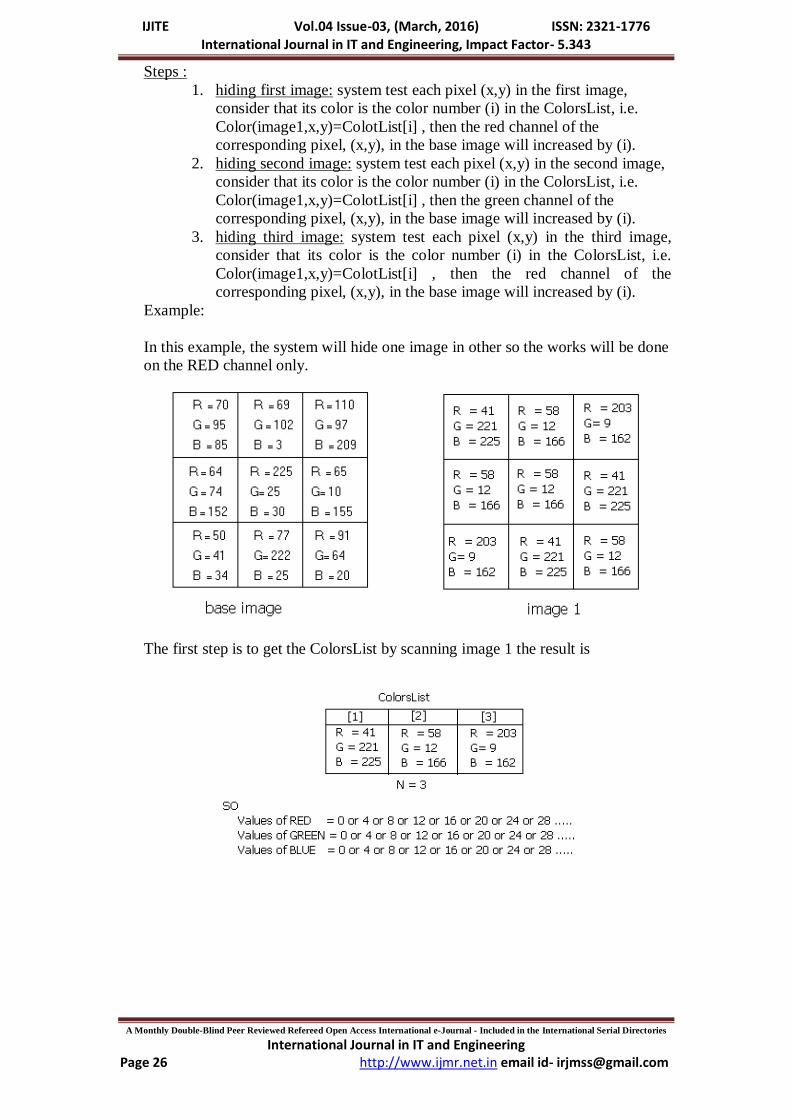
Steps :
1. hiding first image: system test each pixel (x,y) in the first image,
consider that its color is the color number (i) in the ColorsList, i.e.
Color(image1,x,y)=ColotList[i] , then the red channel of the
corresponding pixel, (x,y), in the base image will increased by (i).
2. hiding second image: system test each pixel (x,y) in the second image,
consider that its color is the color number (i) in the ColorsList, i.e.
Color(image1,x,y)=ColotList[i] , then the green channel of the
corresponding pixel, (x,y), in the base image will increased by (i).
3. hiding third image: system test each pixel (x,y) in the third image,
consider that its color is the color number (i) in the ColorsList, i.e.
Color(image1,x,y)=ColotList[i] , then the red channel of the
corresponding pixel, (x,y), in the base image will increased by (i).
Example:
In this example, the system will hide one image in other so the works will be done
on the RED channel only.
The first step is to get the ColorsList by scanning image 1 the result is
IJITE Vol.04 Issue-03, (March, 2016) ISSN: 2321-1776 International Journal in IT and Engineering, Impact Factor- 5.343
A Monthly Double-Blind Peer Reviewed Refereed Open Access International e-Journal - Included in the International Serial Directories
International Journal in IT and Engineering http://www.ijmr.net.in email id- [email protected] Page 27
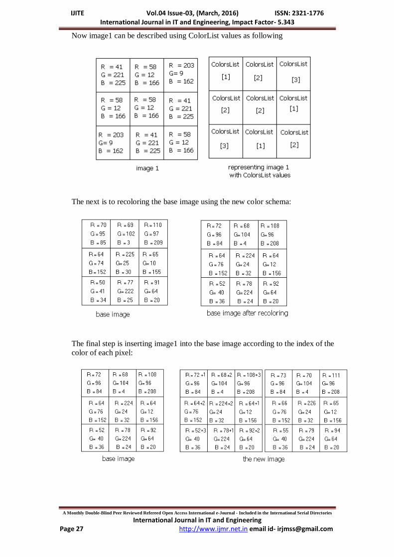
Now image1 can be described using ColorList values as following
The next is to recoloring the base image using the new color schema:
The final step is inserting image1 into the base image according to the index of the
color of each pixel:
IJITE Vol.04 Issue-03, (March, 2016) ISSN: 2321-1776 International Journal in IT and Engineering, Impact Factor- 5.343
A Monthly Double-Blind Peer Reviewed Refereed Open Access International e-Journal - Included in the International Serial Directories
International Journal in IT and Engineering http://www.ijmr.net.in email id- [email protected] Page 28
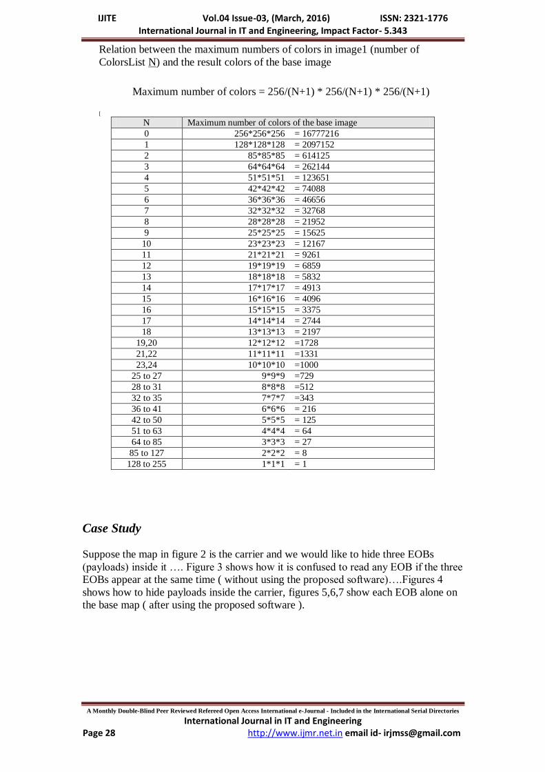
Relation between the maximum numbers of colors in image1 (number of
ColorsList N) and the result colors of the base image
Maximum number of colors = 256/(N+1) * 256/(N+1) * 256/(N+1)
[
N Maximum number of colors of the base image
0 256*256*256 = 16777216
1 128*128*128 = 2097152
2 85*85*85 = 614125
3 64*64*64 = 262144
4 51*51*51 = 123651
5 42*42*42 = 74088
6 36*36*36 = 46656
7 32*32*32 = 32768
8 28*28*28 = 21952
9 25*25*25 = 15625
10 23*23*23 = 12167
11 21*21*21 = 9261
12 19*19*19 = 6859
13 18*18*18 = 5832
14 17*17*17 = 4913
15 16*16*16 = 4096
16 15*15*15 = 3375
17 14*14*14 = 2744
18 13*13*13 = 2197
19,20 12*12*12 =1728
21,22 11*11*11 =1331
23,24 10*10*10 =1000
25 to 27 9*9*9 =729
28 to 31 8*8*8 =512
32 to 35 7*7*7 =343
36 to 41 6*6*6 = 216
42 to 50 5*5*5 = 125
51 to 63 4*4*4 = 64
64 to 85 3*3*3 = 27
85 to 127 2*2*2 = 8
128 to 255 1*1*1 = 1
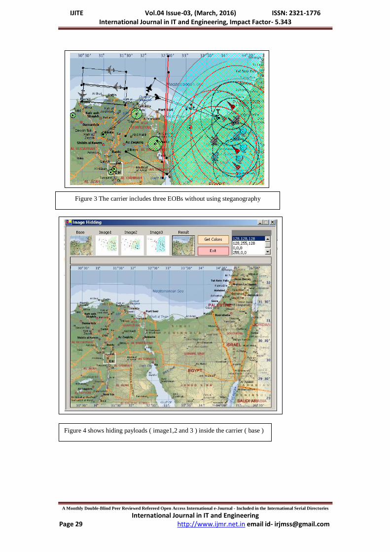
Case Study
Suppose the map in figure 2 is the carrier and we would like to hide three EOBs
(payloads) inside it …. Figure 3 shows how it is confused to read any EOB if the three
EOBs appear at the same time ( without using the proposed software)….Figures 4
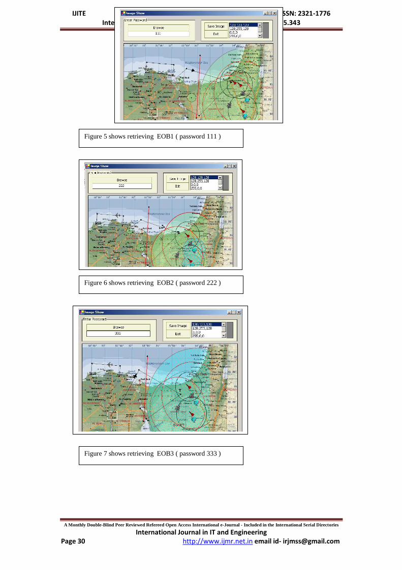
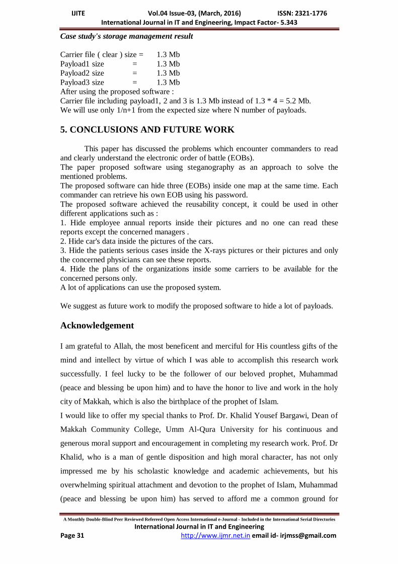
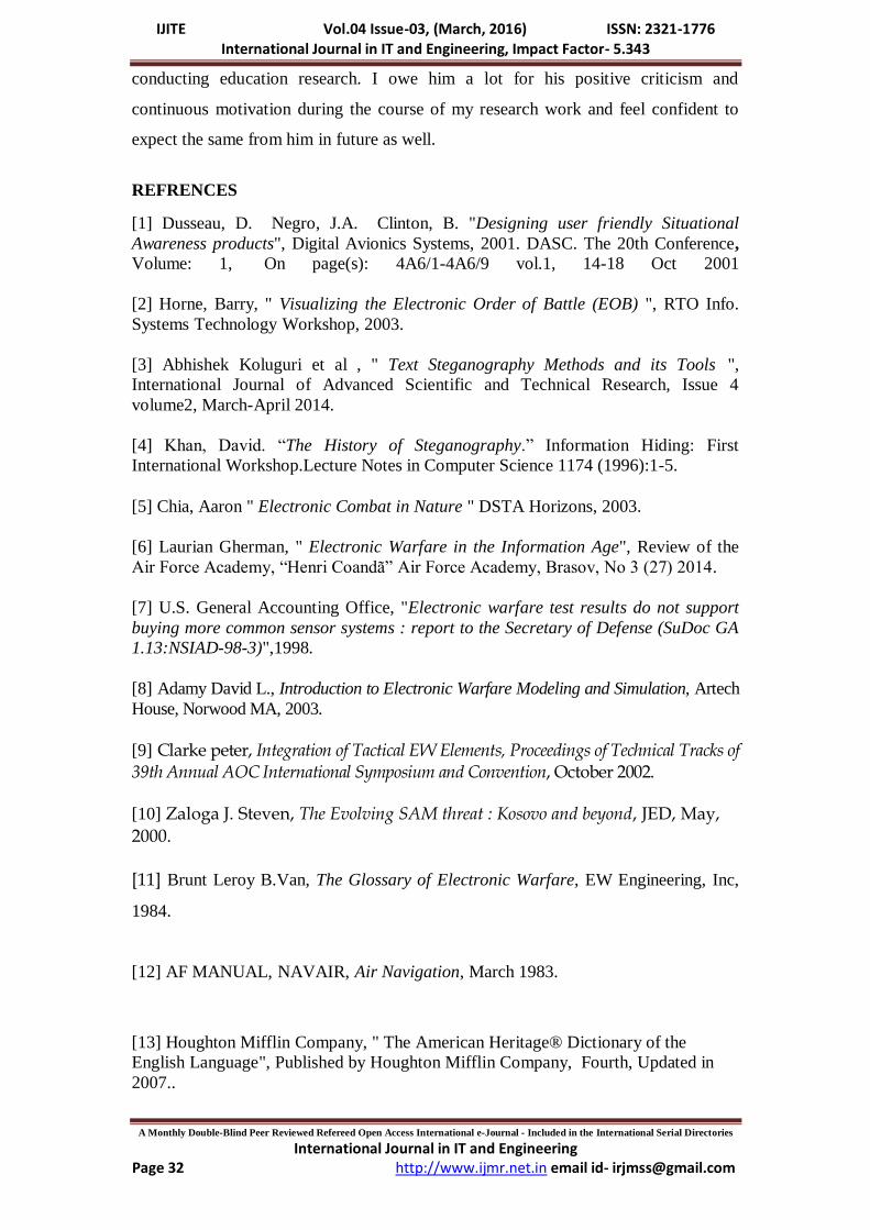
shows how to hide payloads inside the carrier, figures 5,6,7 show each EOB alone on
the base map ( after using the proposed software ).
IJITE Vol.04 Issue-03, (March, 2016) ISSN: 2321-1776 International Journal in IT and Engineering, Impact Factor- 5.343
A Monthly Double-Blind Peer Reviewed Refereed Open Access International e-Journal - Included in the International Serial Directories
International Journal in IT and Engineering http://www.ijmr.net.in email id- [email protected] Page 29
Figure 3 The carrier includes three EOBs without using steganography
Figure 4 shows hiding payloads ( image1,2 and 3 ) inside the carrier ( base )
IJITE Vol.04 Issue-03, (March, 2016) ISSN: 2321-1776 International Journal in IT and Engineering, Impact Factor- 5.343
A Monthly Double-Blind Peer Reviewed Refereed Open Access International e-Journal - Included in the International Serial Directories
International Journal in IT and Engineering http://www.ijmr.net.in email id- [email protected] Page 30
Figure 6 shows retrieving EOB2 ( password 222 )
Figure 7 shows retrieving EOB3 ( password 333 )
Figure 5 shows retrieving EOB1 ( password 111 )
IJITE Vol.04 Issue-03, (March, 2016) ISSN: 2321-1776 International Journal in IT and Engineering, Impact Factor- 5.343
A Monthly Double-Blind Peer Reviewed Refereed Open Access International e-Journal - Included in the International Serial Directories
International Journal in IT and Engineering http://www.ijmr.net.in email id- [email protected] Page 31
Case study's storage management result
Carrier file ( clear ) size = 1.3 Mb
Payload1 size = 1.3 Mb
Payload2 size = 1.3 Mb
Payload3 size = 1.3 Mb
After using the proposed software :
Carrier file including payload1, 2 and 3 is 1.3 Mb instead of 1.3 * 4 = 5.2 Mb.
We will use only 1/n+1 from the expected size where N number of payloads.
5. CONCLUSIONS AND FUTURE WORK
This paper has discussed the problems which encounter commanders to read
and clearly understand the electronic order of battle (EOBs).
The paper proposed software using steganography as an approach to solve the
mentioned problems.
The proposed software can hide three (EOBs) inside one map at the same time. Each
commander can retrieve his own EOB using his password.
The proposed software achieved the reusability concept, it could be used in other
different applications such as :
1. Hide employee annual reports inside their pictures and no one can read these
reports except the concerned managers .
2. Hide car's data inside the pictures of the cars.
3. Hide the patients serious cases inside the X-rays pictures or their pictures and only
the concerned physicians can see these reports.
4. Hide the plans of the organizations inside some carriers to be available for the
concerned persons only.
A lot of applications can use the proposed system.
We suggest as future work to modify the proposed software to hide a lot of payloads.
Acknowledgement
I am grateful to Allah, the most beneficent and merciful for His countless gifts of the
mind and intellect by virtue of which I was able to accomplish this research work
successfully. I feel lucky to be the follower of our beloved prophet, Muhammad
(peace and blessing be upon him) and to have the honor to live and work in the holy
city of Makkah, which is also the birthplace of the prophet of Islam.
I would like to offer my special thanks to Prof. Dr. Khalid Yousef Bargawi, Dean of
Makkah Community College, Umm Al-Qura University for his continuous and
generous moral support and encouragement in completing my research work. Prof. Dr
Khalid, who is a man of gentle disposition and high moral character, has not only
impressed me by his scholastic knowledge and academic achievements, but his
overwhelming spiritual attachment and devotion to the prophet of Islam, Muhammad
(peace and blessing be upon him) has served to afford me a common ground for
IJITE Vol.04 Issue-03, (March, 2016) ISSN: 2321-1776 International Journal in IT and Engineering, Impact Factor- 5.343
A Monthly Double-Blind Peer Reviewed Refereed Open Access International e-Journal - Included in the International Serial Directories
International Journal in IT and Engineering http://www.ijmr.net.in email id- [email protected] Page 32
conducting education research. I owe him a lot for his positive criticism and
continuous motivation during the course of my research work and feel confident to
expect the same from him in future as well.
REFRENCES
[1] Dusseau, D. Negro, J.A. Clinton, B. "Designing user friendly Situational
Awareness products", Digital Avionics Systems, 2001. DASC. The 20th Conference,
Volume: 1, On page(s): 4A6/1-4A6/9 vol.1, 14-18 Oct 2001
[2] Horne, Barry, " Visualizing the Electronic Order of Battle (EOB) ", RTO Info.
Systems Technology Workshop, 2003.
[3] Abhishek Koluguri et al , " Text Steganography Methods and its Tools ",
International Journal of Advanced Scientific and Technical Research, Issue 4
volume2, March-April 2014.
[4] Khan, David. “The History of Steganography.” Information Hiding: First
International Workshop.Lecture Notes in Computer Science 1174 (1996):1-5.
[5] Chia, Aaron " Electronic Combat in Nature " DSTA Horizons, 2003.
[6] Laurian Gherman, " Electronic Warfare in the Information Age", Review of the
Air Force Academy, “Henri Coandã” Air Force Academy, Brasov, No 3 (27) 2014.
[7] U.S. General Accounting Office, "Electronic warfare test results do not support
buying more common sensor systems : report to the Secretary of Defense (SuDoc GA
1.13:NSIAD-98-3)",1998.
[8] Adamy David L., Introduction to Electronic Warfare Modeling and Simulation, Artech
House, Norwood MA, 2003.
[9] Clarke peter, Integration of Tactical EW Elements, Proceedings of Technical Tracks of 39th Annual AOC International Symposium and Convention, October 2002.
[10] Zaloga J. Steven, The Evolving SAM threat : Kosovo and beyond, JED, May,
2000. [11] Brunt Leroy B.Van, The Glossary of Electronic Warfare, EW Engineering, Inc,
1984.
[12] AF MANUAL, NAVAIR, Air Navigation, March 1983.
[13] Houghton Mifflin Company, " The American Heritage® Dictionary of the
English Language", Published by Houghton Mifflin Company, Fourth, Updated in
2007..
IJITE Vol.04 Issue-03, (March, 2016) ISSN: 2321-1776 International Journal in IT and Engineering, Impact Factor- 5.343
A Monthly Double-Blind Peer Reviewed Refereed Open Access International e-Journal - Included in the International Serial Directories
International Journal in IT and Engineering http://www.ijmr.net.in email id- [email protected] Page 33
[14] Mangarae Aelphaeis, " Steganography FAQ" Zone-H.Org, March 18th 2006.
[15] Neil F. Johnson, "Introduction to Steganography & Steganalysis" , Steganography
& Digital Watermarking for Workshop on Statistical and Machine Learning
Techniques in Computer Intrusion Detection, Johns Hopkins University, June 11-13,
2002.
[16] Maninder Singh Rana et al., “ Art of Hiding: An Introduction to Steganography”
International Journal Of Engineering And Computer Science Volume1 Issue 1 Oct
2012 Page No. 11-22
[17] Arihant Gaggar et al., “Steganography” international Journal of Students
Research in Technology & Management, Vol 1(2), April 2013, pg 253-259
[18] Judge C. James, " Steganography: Past, Present, Future", SANS Institute Version
1.2f , 2001.
[19] Clair Bryan "Steganography: How to Send a Secret Message", October 2001.