Embed Size (px)
Citation preview

Rajnee Bala Minz et al www.ijetst.in Page 835
IJETST- Volume||01||Issue||06||Pages 835-840||August||ISSN 2348-9480 2014
International journal of Emerging Trends in Science and Technology
Simulation and Speed Control of Induction Motor Using Fuzzy Logic PID Controller
Authors
Rajnee Bala Minz1, Rajesh Thinga
2, C.S. Sharma
3
1PG Scholar/ Dept. of EE, Samrat Ashok Technological Institute, Vidisha, M.P, India
Email: [email protected] 2PG Scholar/Dept. of EE, Samrat Ashok Technological Institute, Vidisha, M.P, India
Email: [email protected] 3Associate Prof./Dept of EE, Samrat Ashok Technological Institute, Vidisha, M.P, India
Email: [email protected]
Abstract:
Three phase induction motor drives have various industrial applications. In this thesis work indirect vector control technique
is used which is based upon the Fuzzy PID speed controller. This method of speed control using fuzzy logic in induction
motor altogether forms a closed loop control system. Result evaluated and obtained for speed control in Simulink provides
reasonable accurate output at the end.
This thesis provides a technique for implementing a rule-based fuzzy logic PID controller applied to a closed loop indirect
vector control the speed control of an induction motor. In this the d-q axis theory is used for the modeling of induction motor.
For the speed control of IM using indirect vector control technique, a reference speed has been used and the control
architecture includes the rule base. The controller has been tuned by hit and trial error method. The errors in the system are
evaluated according to the rules which have defined membership functions. Keywords: Induction motor, Fuzzy logic controller, Indirect vector control, PID Controller, closed loop parameters.
INTRODUCTION
Ac motors, particularly squirrel-cage induction motor have
many inherent advantages like simplicity, reliability, low cost
and virtually maintenance-free [3]. Three phase drives are
widely used in electrical drive application.There are number of
significant control methods available for induction motors
including scalar control, vector or field oriented control, direct
torque and flux control, sliding mode control and the adaptive
fuzzy control. The numerous successful applications of fuzzy
control have sparked a flurry of activities in the analysis and
design of fuzzy control. In the last few years, fuzzy logic has
met a growing interest in many motor control applications due
to its non-line arities handling features and independence of
the plant modelling. The fuzzy controller (FLC) operates in a
knowledge-based way, and its knowledge relies on a set of
linguistic if-then rules, like a human operator.
INDUCTION MOTOR DRIVES
Three phase induction motors are of two types: squirrel cage
and wound rotor.Squirrel cage induction motors are very
popular in variable-speed drives due to simple, ruggedness and inexpensive too. These are available at all power ratings [ 7]. In squirrel-cage, the rotor consists of longitudinal conductor-bars shorted by circular connectors at the two ends while in wound-
rotor motor, the rotor also has a balanced three-phase distributed winding having same poles as stator winding. However, in both, stator carries a three-phase balanced distributed winding [5].
A. Analysis and performance
Per-phase equivalent circuit of a three-phase induction motor is shown in fig. 1(a).
Fig.1(a) fig.1(b)
R’r and X’r are the stator referred values of rotor resistance Rr and rotor reactance Xr. Slip is defined by
s=
(1)
Where, Wm and Wms are rotor and synchronous speeds, respectively. Further
Wms=
rad/sec (2)

Rajnee Bala Minz et al www.ijetst.in Page 836
IJETST- Volume||01||Issue||06||Pages 835-840||August||ISSN 2348-9480 2014
Where f and p are supply frequency and number of poles, respectively.
Since, stator impedence drop is generally negligible compared to terminal voltage V, the equivalent circuit can be simplified to that shown in fig. 1(b).
Also from eqn 1.
Wm= Wms(1-s) (3)
From fig.2
I’r=V
(4)
Power transferred to rotor (or air-gap power)
Pg= 3 I’r ² R’r s (5)
Rotor copper loss is
Pcu=3 I’r ²R’r (6)
Electrical power converted into mechanical power
Pm= Pg – Pcu =3 I’r ²R’r
) (7)
Torque developed by motor
T= Pm/Wm (8)
From equation (3) and (7)
T=
² /s (9)
From equation (4)
T=
²
] (10)
Comparing equation (5) and (9)
T=
(11)
Motor output torque is obtained by deducting friction windage and core-loss torques from the developed torque [5].
The developed torque is a function of slip only. Differentiating T in equation (10) w.r.t ‘s’ and equating to zero gives the slip for maximum torque
Sm=±
(12)
Substituting equation (12) in (10) yields expression for maximum torque
Tmax=
(13)
SPEED CONTROL FOR INDUCTION MOTOR
Usually a motor draws 5 to 7 times rated current during starting. When load torque during starting and motor-load-inertia are not large, the starting process is over in few seconds and therefore, motor temperature does not exceed the permissible value. In such applications motor can always be started direct on line, provided the voltage dip caused by large starting current is not beyond a permissible value.
When either the load torque during starting is high or load inertia is large, the starting process takes long time. If motor carries large current during starting, it will get damaged due to overheating. Therefore, motor cannot be started direct on line. Hence various methods are used for improved starting [5].
A controller is a device which controls each & every operation
in the system making decisions. From the control system point
of view, it is bringing stability to the system when there is a
disturbance, thus safeguarding the equipment from further
damages. It may be hardware based controller or a software
based controller or a combination of both[6 ].
Following methods are the significant control methods available for induction motors including scalar control, vector or field oriented control, direct torque and flux control, sliding mode control and adaptive fuzzy control.
B. Scalar Control
Synchronous speed, therefore, the motor speed can be controlled by varying supply frequency. Voltage induced in stator is proportional to the product of supply frequency and air-gap flux. If stator drop is neglected, terminal voltage can be considered proportional to the product of frequency and flux. Any reduction in the supply frequency, without a change in the terminal voltage, causes an increase in the air-gap flux.
C. Vector Control
Vector control, also called Field-oriented controlFOC), is
a variable frequency drive (VFD) control method which
controlsthree-phase AC electric motor output by means of two
controllable VFD inverter output variables:
Voltage magnitude
Frequency
FOC is a control technique that is used in AC
synchronous and Induction motor applications that was
originally developed for high-performance motor applications
which can operate smoothly over the full speed range, can
generate full torque at zero speed, and is capable of fast
acceleration and deceleration but that is becoming increasingly
attractive for lower performance applications as well due to
FOC's motor size, cost and power consumption reduction
superiority.
Not only is FOC very common in induction motor control
applications due to its traditional superiority in high-
performance applications, but the expectation is that it will
eventually nearly universally displace single-
variable scalar volts-per-Hertz (V/f) control.
D. Direct Torque and Flux Control
Direct torque control (DTC) is one method used in variable frequency drives to control the torque (and thus finally thespeed) of three-phase AC electric motors. This involves calculating an estimate of the motor's magnetic flux and torque based on the measured voltage and current of
the motor.
Stator flux linkage is estimated by integrating the stator voltages. Torque is estimated as

Rajnee Bala Minz et al www.ijetst.in Page 837
IJETST- Volume||01||Issue||06||Pages 835-840||August||ISSN 2348-9480 2014
a cross product of estimated stator flux linkage vector and measured motor current vector. The estimated flux magnitude and torque are then compared with their reference values. If either the estimated flux or torque deviates from the reference more than allowed tolerance, the transistors of the variable frequency drive are turned off and on in such a way that the flux and torque errors will return in their tolerant bands as fast as possible. Thus direct torque control is one form of the
hysteresis or bang-bang control.
E. Fuzzy Logic Control
A fuzzy control system is a control system based
on fuzzy logic—a mathematical system that
analyzes analog input values in terms of logical variables that
take on continuous values between 0 and 1, in contrast to
classical or digital logic, which operates on discrete values of
either 1 or 0 (true or false, respectively).Fuzzy logic is widely
used in machine control. The term "fuzzy" refers to the fact
that the logic involved can deal with concepts that cannot be
expressed as "true" or "false" but rather as "partially true".
Although alternative approaches such as genetic algorithms
and neural networks can perform just as well as fuzzy logic in
many cases, fuzzy logic has the advantage that the solution to
the problem can be cast in terms that human operators can
understand, so that their experience can be used in the design
of thecontroller. This makes it easier to mechanize tasks that
are already successfully performed by humans.
The main use of fuzzy control system is based on
empirical rules is more effective. Fuzzy systems are easily
upgraded by adding new rules or new features to improve
performance. Fuzzy control can be used to improve existing
traditional control systems by adding a layer of intelligence to
the current control method. The fuzzy logic controller consists
of Fuzzy Inference System Editor. The output of the controller
is crisp value. This Graphical User Interface consists of FIS
Editor, Membership function Editor, Rule Editor, Rule Viewer
and Surface Viewer [ 8].
Fuzzy sets support a flexible sense of membership and is
defined to be the pair (x , µÃ(x)) where µÃ (x) could be
discrete or could be described by continuous function.
Fuzzy set theory is an effective tool to tackle the problem of
uncertainty [ 4].
Fuzzy Sets:
Fuzzy sets support a flexible sense of membership of elements
to a set. While in crisp set theory, an element either belongs to
or does not belong to a set, in fuzzy set theory many degrees
of membership (between 0 or 1) are allowed [4]. The input
variables in a fuzzy control system are in general mapped by
sets of membership functions similar to this, known as "fuzzy
sets". The process of converting a crisp input value to a fuzzy
value is called “fuzzification".
Fuzzy control system design is based on empirical methods,
basically a methodical approach to trial-and-error [4]. The
general process is as follows:
o Document the system's operational specifications and
inputs and outputs.
o Document the fuzzy sets for the inputs.
o Document the rule set.
o Determine the defuzzification method.
o Run through test suite to validate system, adjust
details as required.
Complete document and release to production.
The block diagram below shows the speed control
system using FLC. The FLC has two inputs and
speed errors and change in speed error and output
which represents the change in quadrature reference
current.
Fig.3 Block Diagram of fuzzy controller
Fuzzy Rule:
A fuzzy rule is defined as a conditional statement in the form:
IF x is A
THEN y is B
where x and y are linguistic variables; A and B are linguistic
values determined by fuzzy sets on the universe of
discourse X and Y, respectively [4].
To determine a fuzzy rule from each input-output data pair,
the first step is to find the degree of each data value in every
membership region of its corresponding fuzzy domain. The
variable is then assigned to the region with the maximum
degree. When each new rule is generated from the input-
output data pairs, a rule degree or truth is assigned to that rule,
where this rule degree is defined as the degree of confidence
in the developed method a degree is assigned which is the
product of the membership function degree of each variable in
its respective region [7].

Rajnee Bala Minz et al www.ijetst.in Page 838
IJETST- Volume||01||Issue||06||Pages 835-840||August||ISSN 2348-9480 2014
Fig. 4 fuzzy rule viewer
RULES IN FLC:
Membership Functions:
The membership function of a fuzzy set is a generalization of the indicator function in classical sets. In fuzzy logic, it represents the degree of truth as an extension of valuation. Degrees of truth are often confused with probabilities, although they are conceptually distinct, because fuzzy truth represents membership in vaguely defined sets, not likelihood of some event or condition.
Fig. 5 Both I/Ps membership functions
TABLE1- Relationship between e(k) and de(k)
e(k)→
de(k)↓
NB NM NS ZE PS PM PB
NB NB NB NM NM NS ZE ZE
NM NB NB NM NS NS ZE ZE
NS NB NM NS NS ZE PS PS
ZE NM NM NS ZE PS PM PM
PS NM NS ZE PS PS PM PB
PM ZE ZE PS PS PM PB PB
PB ZE ZE PS PM PM PB PB
ABBREVIATIONS USED IN FUZZY RULE BOX
NB- NEGATIVE BIG
NM- NEGATIVE MEDIUM
NS- NEGATIVE SMALL
ZE- ZERO
PS- POSITIVE SMALL
PM- POSITIVE MEDIUM
PB- POSITIVE BIG
Fig.6 Output membership function
SIMULATION CIRCUIT
Fig.7 Speed controller using FLC.
Rajnee Bala Minz et al www.ijetst.in Page 839
IJETST- Volume||01||Issue||06||Pages 835-840||August||ISSN 2348-9480 2014
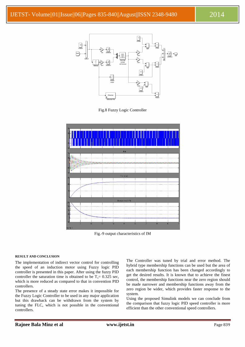
Fig.8 Fuzzy Logic Controller
Fig.-9 output characteristics of IM
RESULT AND CONCLUSION
The implementation of indirect vector control for controlling
the speed of an induction motor using Fuzzy logic PID
controller is presented in this paper. After using the fuzzy PID
controller the saturation time is obtained to be Ts= 0.325 sec,
which is more reduced as compared to that in convention PID
controllers.
The presence of a steady state error makes it impossible for
the Fuzzy Logic Controller to be used in any major application
but this drawback can be withdrawn from the system by
tuning the FLC, which is not possible in the conventional
controllers.
The Controller was tuned by trial and error method. The
hybrid type membership functions can be used but the area of
each membership function has been changed accordingly to
get the desired results. It is known that to achieve the finest
control, the membership functions near the zero region should
be made narrower and membership functions away from the
zero region be wider, which provides faster response to the
system.
Using the proposed Simulink models we can conclude from
the comparison that fuzzy logic PID speed controller is more
efficient than the other conventional speed controllers.

Rajnee Bala Minz et al www.ijetst.in Page 840
IJETST- Volume||01||Issue||06||Pages 835-840||August||ISSN 2348-9480 2014
REFERENCE
1. Weibo Yu, Yan Wang,Dejiang Zhang,Research on
Variable Frequency Energy- Saving control strategy
of Precooling Water Pump, 978-1-4244-8165-1/11,
2011, IEEE.
2. Simulation of Vector Control Frequency Converter of
Induction Motor Based on Matlab/Simulink, Wu
Tao,Zhao Liang,978-0-7695-4296-6/11, 2011 IEEE.
3. Fuzzy Logic Based MRAS For Sensorless Induction
Motor Drive, Z.M.Salem,
M.M.Khater,S.A.Mahmoud, MEPCON’2006.
4. Neural Networks, Fuzzy Logic, and Genetic
Algorithms, Synthesis and Applications,by
`S.Rajasekaran and G.A.Vijayalakshmi Pai,PHI
LearningPrivate Limited.
5. Fundamentals of Electric Drives by Gopal. K. Dubey
,Second Edition, Narosa Publishing House Pvt. Ltd.
6. Modelling of Induction motor and control of speed
using hybrid controller technology, Ashok Kusagur,
Dr. S.F.Kodad, Dr. B.V. Sankar Ram,.
7. Performance optimization of asynchronous machine
using fuzzy voltage controller, A.A.Ansari and
D.M..Deshpande,IJET2(1): 45-49(2011).
8. Fuzzy PID controller application to sensorless
induction motor on model reference adaptive
system(MRAS), M.L.N.Kiran Kumar, T.Rama Sastry
, ISSN (Print) : 2320 – 3765ISSN (Online): 2278 –
8875, 2003.
9. Induction motor speed control using Fuzzy Logic
controller, V.Chitra and R.S.Prabhakar.
10. Ziegler-Nichols (Z-N) Based PID Plus Fuzzy Logic
Control (FLC) For Speed Control of A Direct Field-
Oriented Induction Motor (DFOIM),
11. Srinivas.Singirikonda, Yellaiah.Ponnam, Sravan
Kumar.Palarapu
12. ISSN: 2248-9622, Vol. 3, Issue 6, Nov-Dec 2013,
pp.755-762.
13. Fuzzy gain scheduling of PID controller, Zhen-Yu-
Zhao, Masayoshi Tomizuka and Saturo Isaka, vol. 23
no. 5,september/ october 1993, IEEE.
14. New Results on the Synthesis of PID
Controllers,Guillermo J. Silva, Aniruddha Datta, and
S. P. Bhattacharyya, IEEE Transactions on automatic